EP3399215A1 - Spindle drive - Google Patents
Spindle drive Download PDFInfo
- Publication number
- EP3399215A1 EP3399215A1 EP17169766.7A EP17169766A EP3399215A1 EP 3399215 A1 EP3399215 A1 EP 3399215A1 EP 17169766 A EP17169766 A EP 17169766A EP 3399215 A1 EP3399215 A1 EP 3399215A1
- Authority
- EP
- European Patent Office
- Prior art keywords
- spindle
- threaded
- threaded spindle
- plastic
- flats
- Prior art date
- Legal status (The legal status is an assumption and is not a legal conclusion. Google has not performed a legal analysis and makes no representation as to the accuracy of the status listed.)
- Granted
Links
Images


Classifications
-
- F—MECHANICAL ENGINEERING; LIGHTING; HEATING; WEAPONS; BLASTING
- F16—ENGINEERING ELEMENTS AND UNITS; GENERAL MEASURES FOR PRODUCING AND MAINTAINING EFFECTIVE FUNCTIONING OF MACHINES OR INSTALLATIONS; THERMAL INSULATION IN GENERAL
- F16H—GEARING
- F16H25/00—Gearings comprising primarily only cams, cam-followers and screw-and-nut mechanisms
- F16H25/18—Gearings comprising primarily only cams, cam-followers and screw-and-nut mechanisms for conveying or interconverting oscillating or reciprocating motions
- F16H25/20—Screw mechanisms
-
- B—PERFORMING OPERATIONS; TRANSPORTING
- B01—PHYSICAL OR CHEMICAL PROCESSES OR APPARATUS IN GENERAL
- B01L—CHEMICAL OR PHYSICAL LABORATORY APPARATUS FOR GENERAL USE
- B01L3/00—Containers or dishes for laboratory use, e.g. laboratory glassware; Droppers
- B01L3/02—Burettes; Pipettes
- B01L3/021—Pipettes, i.e. with only one conduit for withdrawing and redistributing liquids
- B01L3/0217—Pipettes, i.e. with only one conduit for withdrawing and redistributing liquids of the plunger pump type
- B01L3/0227—Details of motor drive means
-
- F—MECHANICAL ENGINEERING; LIGHTING; HEATING; WEAPONS; BLASTING
- F16—ENGINEERING ELEMENTS AND UNITS; GENERAL MEASURES FOR PRODUCING AND MAINTAINING EFFECTIVE FUNCTIONING OF MACHINES OR INSTALLATIONS; THERMAL INSULATION IN GENERAL
- F16H—GEARING
- F16H25/00—Gearings comprising primarily only cams, cam-followers and screw-and-nut mechanisms
- F16H25/18—Gearings comprising primarily only cams, cam-followers and screw-and-nut mechanisms for conveying or interconverting oscillating or reciprocating motions
- F16H25/20—Screw mechanisms
- F16H25/24—Elements essential to such mechanisms, e.g. screws, nuts
-
- G—PHYSICS
- G01—MEASURING; TESTING
- G01B—MEASURING LENGTH, THICKNESS OR SIMILAR LINEAR DIMENSIONS; MEASURING ANGLES; MEASURING AREAS; MEASURING IRREGULARITIES OF SURFACES OR CONTOURS
- G01B3/00—Measuring instruments characterised by the use of mechanical techniques
- G01B3/18—Micrometers
-
- F—MECHANICAL ENGINEERING; LIGHTING; HEATING; WEAPONS; BLASTING
- F16—ENGINEERING ELEMENTS AND UNITS; GENERAL MEASURES FOR PRODUCING AND MAINTAINING EFFECTIVE FUNCTIONING OF MACHINES OR INSTALLATIONS; THERMAL INSULATION IN GENERAL
- F16H—GEARING
- F16H25/00—Gearings comprising primarily only cams, cam-followers and screw-and-nut mechanisms
- F16H25/18—Gearings comprising primarily only cams, cam-followers and screw-and-nut mechanisms for conveying or interconverting oscillating or reciprocating motions
- F16H25/20—Screw mechanisms
- F16H2025/2062—Arrangements for driving the actuator
- F16H2025/2081—Parallel arrangement of drive motor to screw axis
-
- F—MECHANICAL ENGINEERING; LIGHTING; HEATING; WEAPONS; BLASTING
- F16—ENGINEERING ELEMENTS AND UNITS; GENERAL MEASURES FOR PRODUCING AND MAINTAINING EFFECTIVE FUNCTIONING OF MACHINES OR INSTALLATIONS; THERMAL INSULATION IN GENERAL
- F16H—GEARING
- F16H25/00—Gearings comprising primarily only cams, cam-followers and screw-and-nut mechanisms
- F16H25/18—Gearings comprising primarily only cams, cam-followers and screw-and-nut mechanisms for conveying or interconverting oscillating or reciprocating motions
- F16H25/20—Screw mechanisms
- F16H25/24—Elements essential to such mechanisms, e.g. screws, nuts
- F16H2025/2481—Special features for facilitating the manufacturing of spindles, nuts, or sleeves of screw devices
-
- F—MECHANICAL ENGINEERING; LIGHTING; HEATING; WEAPONS; BLASTING
- F16—ENGINEERING ELEMENTS AND UNITS; GENERAL MEASURES FOR PRODUCING AND MAINTAINING EFFECTIVE FUNCTIONING OF MACHINES OR INSTALLATIONS; THERMAL INSULATION IN GENERAL
- F16H—GEARING
- F16H25/00—Gearings comprising primarily only cams, cam-followers and screw-and-nut mechanisms
- F16H25/18—Gearings comprising primarily only cams, cam-followers and screw-and-nut mechanisms for conveying or interconverting oscillating or reciprocating motions
- F16H25/20—Screw mechanisms
- F16H25/24—Elements essential to such mechanisms, e.g. screws, nuts
- F16H2025/249—Special materials or coatings for screws or nuts
-
- G—PHYSICS
- G01—MEASURING; TESTING
- G01N—INVESTIGATING OR ANALYSING MATERIALS BY DETERMINING THEIR CHEMICAL OR PHYSICAL PROPERTIES
- G01N35/00—Automatic analysis not limited to methods or materials provided for in any single one of groups G01N1/00 - G01N33/00; Handling materials therefor
- G01N35/02—Automatic analysis not limited to methods or materials provided for in any single one of groups G01N1/00 - G01N33/00; Handling materials therefor using a plurality of sample containers moved by a conveyor system past one or more treatment or analysis stations
- G01N35/04—Details of the conveyor system
- G01N2035/0474—Details of actuating means for conveyors or pipettes
- G01N2035/0482—Transmission
- G01N2035/0487—Helix or lead screw
-
- G—PHYSICS
- G01—MEASURING; TESTING
- G01N—INVESTIGATING OR ANALYSING MATERIALS BY DETERMINING THEIR CHEMICAL OR PHYSICAL PROPERTIES
- G01N35/00—Automatic analysis not limited to methods or materials provided for in any single one of groups G01N1/00 - G01N33/00; Handling materials therefor
- G01N35/10—Devices for transferring samples or any liquids to, in, or from, the analysis apparatus, e.g. suction devices, injection devices
- G01N2035/1027—General features of the devices
-
- G—PHYSICS
- G01—MEASURING; TESTING
- G01N—INVESTIGATING OR ANALYSING MATERIALS BY DETERMINING THEIR CHEMICAL OR PHYSICAL PROPERTIES
- G01N35/00—Automatic analysis not limited to methods or materials provided for in any single one of groups G01N1/00 - G01N33/00; Handling materials therefor
- G01N35/10—Devices for transferring samples or any liquids to, in, or from, the analysis apparatus, e.g. suction devices, injection devices
Definitions
- the invention relates to a spindle drive comprising a threaded spindle and a spindle nut, in particular for metrology, positioning and drive technology.
- Spindle drives are used in metrology in particular for measuring lengths or distances.
- An example is the micrometer (formerly called micrometer screw, micrometer), which is used in the form of an external micrometer for the determination of external dimensions, as an internal micrometer for the determination of internal distances and as depth gauge for depth measurement.
- micrometers are used to move measuring marks. They are referred to as Messokulare, Meßschraubenokulare or ocular micrometers.
- Spindle drives are used in positioning technology in particular for positioning and adjustment tasks. A wide field of application of such control devices or actuators is the control technology. Furthermore, spindle drives are used in micro and fine adjustment. Furthermore, spindle drives are used for opening and closing housings and adjusting other parts of the device. In building technology, they are used to open and close doors, gates and windows.
- Spindle drives are used to set the dosing quantity in dosing technology.
- the pipetting devices comprise an adjusting device for adjusting the metering volume with a spindle nut and a threaded spindle, wherein one of these components is fixed and the other is screwed.
- the screwable component has a stop, which with a counter-stop the lift rod cooperates. By adjusting the stop, the stroke of the lifting rod is limited and the dosing volume adjusted.
- linear drives are used, for example, in XYZ transmission systems and other robot arms.
- machine tool technology they serve, for example, the displacement of tool slides.
- Spindle drives are used in dosing technology in order to displace a piston in a cylinder and thereby suck in and expel liquid.
- Electronic dosing devices for dosing liquids comprising an electric dosing drive with spindle drive and electric drive motor are used in particular in scientific and industrial laboratories with medical, molecular biological and pharmaceutical applications.
- the metering device is coupled to a replaceable syringe.
- the electronic dosing drive drives a syringe plunger in a syringe barrel of the syringe.
- the electronic metering device comprises, in addition to the metering drive, a cylinder and a piston displaceable therein and coupled to the metering drive. It also has a sealing seat for sealingly clamping a pipette tip. A hole in the sealing seat is connected to the cylinder via a channel.
- Electronic Handdosiervoriquesen are user-friendly and with only one hand.
- Direct displacement systems are also referred to as electronic dispensers or repeating pipettes.
- Air cushion systems are also referred to as pipettes. These are semi-automatic because they must be manually positioned and operated with the (syringe) piston driven by an electric drive motor.
- LHS liquid handling stations
- WS work stations
- LHS liquid handling stations
- WS work stations
- the robot arm is e.g. an XYZ transmission system.
- spindle drives consist threaded spindle and spindle nut made of metal.
- a disadvantage is the complicated manufacture of the threaded spindle by means of high-precision lathes and post-processing, e.g. by deburring. Furthermore, it can come to a beating of the threaded spindle, if it protrudes with an uncontrolled end further from the spindle nut.
- the spindle drive is susceptible to corrosion. Corrosion increases friction and thus wear and reduces accuracy.
- the spindle drive needs lubricant that binds dust, which increases wear and reduces accuracy. Overload can lead to plastic deformation, which also reduces the precision of the spindle drive.
- Dier EP 2 165 765 B1 describes a pipetting with adjustable dosing volume, wherein the internal thread of the spindle nut or the external thread of the threaded spindle is at least partially formed by screwing the threaded spindle in the spindle nut.
- the two threads made of plastic and the other made of metal. In this way it can be achieved that the threaded spindle is held without play in the spindle nut.
- a disadvantage is the high adjustment forces due to the friction between the two components.
- the DE 10 53 883 A describes a threaded spindle made of sheet metal, which is composed of two U-profile strips, which are welded together at their longitudinal edges. The distance of the weld beads on the two sides of the threaded spindle is smaller than the diameter of the threaded core.
- This threaded spindle is suitable for the driver to take along with simple jack, for clamping devices on work and planing benches, eg in carpentry and glassworks, for screw clamps and other devices in which the spindle is not too high demands on the running characteristics.
- the invention has for its object to provide a simpler to produce and precise working spindle drive.
- the object is achieved by a spindle drive with the features of claim 1.
- Advantageous embodiments of the spindle drive are specified in subclaims.
- the spindle drive has a threaded spindle which is divided into a plurality of threaded regions and a plurality of guide regions.
- a guide portion is disposed on both sides of each guide portion, and a guide portion is disposed on both sides of each threaded portion.
- the threaded areas engage in the internal thread of the spindle nut, whereby the displacement of the threaded spindle is ensured during rotation.
- the guide areas are applied to the core diameter of the internal thread of the spindle nut, so that they are guided in the spindle nut.
- the spindle nut is at the same time a guide bush for the threaded spindle.
- the spindle drive is particularly precise, because the threaded spindle is guided in the spindle nut.
- the threaded spindle is an injection-molded part.
- the threaded spindle is produced by injection molding.
- the subdivision of the threaded spindle in threaded areas and guide areas is advantageous for the production of the threaded spindle by injection molding, since the subdivision of the external thread allows injection molding production by means of an injection mold with multiple moldings.
- the parting line of the injection mold can be placed so that it falls into the guide areas. As a result, undercuts in the threaded areas can be avoided or greatly reduced, which hinder the removal of the threaded spindle from the injection mold and affect the precision.
- the costs for the production of the threaded spindle can be reduced and a reworking can be saved.
- the threaded spindle consists of a first plastic.
- the threaded spindle made of plastic has improved sliding properties. This reduces wear and reduces the loss of precision.
- the corrosion resistance and chemical resistance of the threaded spindle made of plastic reduces wear and the associated loss of precision.
- plastics with improved sliding properties are available so that lubricant can be eliminated, which binds dust and causes wear and loss of precision. But it is also possible to improve the sliding properties by applying small amounts of lubricant yet. Due to the reduced friction between the threaded spindle and the spindle nut is The power consumption of the engine lowered and the battery life increased. Finally, the weight of the spindle drive is reduced by the threaded spindle made of plastic.
- the threaded spindle made of plastic is an injection molded part.
- the threaded spindle made of plastic is a sintered part, that is, the threaded spindle is produced by sintering of plastic particles.
- the threaded spindle made of plastic by cutting, rolling and / or milling.
- the threaded spindle made of plastic is produced by 3D printing.
- the threaded spindle is made of metal. According to another embodiment, the threaded spindle is made of metal by cutting, rolling and / or milling. According to a further embodiment, the threaded spindle is made of metal by sintering metal powder.
- the threaded spindle MIM Metal Injection Molding
- a metal powder is mixed with a plastic matrix and injection-molded.
- the result is a threaded spindle made entirely or essentially of metal because the plastic is removed during the manufacturing process.
- the spindle drive is particularly suitable for applications in which it depends on precision, smoothness and low weight of the drive.
- the nominal core diameter of the internal thread is equal to the nominal diameter of the threaded spindle at the guide areas.
- the nominal diameter at the guide areas is the diameter of the smallest circle touching and fully enveloping the guide areas.
- the tolerances of the two diameters are chosen so that there is a clearance fit.
- a tolerance H11 is chosen that allows a deviation of 0 to + 75 ⁇ m from the nominal diameter.
- a tolerance d9 is selected for the outer diameter of the guide regions, which allows a deviation from the nominal diameter of -30 microns to -60 microns.
- the clearance between internal thread and guide ribs minimally 30 microns and a maximum of 135 microns.
- the game of clearance fit is according to a preferred embodiment, a maximum of 150 microns and a minimum of 0 microns, more preferably at most 135 microns and a minimum of 30 microns.
- the flats carry guide ribs which have the guide areas at the outer ends.
- guide ribs are advantageous for the production of the threaded spindle by injection molding, because the parting plane of the injection mold can be placed in the plane of the guide ribs.
- the threaded spindle has only two diametrically opposite first flats into which the parting plane of two Tool halves of an injection mold can be placed.
- only two diametrically opposed guide ribs are present. This allows a relatively simple injection mold with easy demolding and high dimensional accuracy.
- the guide ribs each have at the ends a second flattening and adjacent to the two lateral edges of the second flattening guide areas at a distance from the central axis of the threaded spindle corresponding to half the core diameter of the spindle nut.
- the guide ribs are each guided on the guide areas on both sides of the second flats. This has the advantage that demolding burrs generated during injection molding of the threaded spindle on the second flats do not come into contact with the spindle nut and prevent precise guiding of the threaded spindle in the spindle nut.
- first flats are flat surfaces and / or the second flats are flat surfaces.
- guide ribs project outwardly from first flats formed by flat surfaces. The regions of a first flattening in the form of flat surfaces, which are arranged on different sides of the same guide rib, can be aligned parallel or angled to each other.
- the first flats are curved outwards and / or the second flattenings are curved outwards.
- the radii of curvature of the first flats are greater than half the core diameter of the internal thread of the spindle nut or the same and / or the Curvature radii of the second flats are greater than half the core diameter of the internal thread of the spindle nut.
- the guide areas are at the same time the outwardly curved first flats or partial areas thereof.
- the first flats do not carry guide ribs.
- the first flats may additionally be provided with second flats, wherein the radius of curvature of the second flats is greater than half the core diameter of the spindle nut. Deformation burrs generated during injection molding in the second flats do not come into contact with the spindle nut. Alternatively, demolding burrs are avoided by precise production of the injection mold or removed by post-processing.
- the external thread and the internal thread is a trapezoid thread or a pointed thread or a round thread or a saw thread.
- the threaded portions of the external thread taper outwardly between the first flats in the radial direction. This is advantageous for the removal of the threaded spindle from an injection mold.
- the outer longitudinal edges of the guide ribs and / or the transitions from the guide ribs to the first flat surfaces are rounded. This is advantageous for removal from the injection mold.
- the rounded longitudinal edges of the guide ribs reduce the friction of the threaded spindle in the spindle nut.
- the lateral edges of the thread profiles bounded by the flattened portions are rounded. This will reduce the friction Sliding the lead screw supported in the spindle nut and reduces wear. This is also advantageous for removal from the injection mold.
- the transitions of the flanks of the thread profiles to the core of the threaded spindle and / or the radially outer edges of the thread profiles are rounded.
- the low-friction sliding of the threaded spindle is supported in the spindle nut and reduces wear. This is also advantageous for removal from the injection mold.
- the spindle nut is made of a second plastic and / or of a metal.
- the production of the spindle nut from at least one plastic or from at least one other injection-moldable material can be done by injection molding.
- the injection mold may have a corresponding tool core for generating the internal thread of the spindle nut.
- the production of the spindle nut made of plastic by sintering, cutting, rolling and / or milling or 3D printing done.
- the production of the spindle nut made of metal can be done by thread cutting, thread forming or thread milling, by MIM or by sintering metal powder.
- the first plastic is a high-performance plastic or a technical plastic.
- the first plastic is selected from at least one of the following high-performance plastics: PEEK, PPS, LCP, PPA, PEI, PES, PPSU, PSU, PC-HT.
- the first plastic is selected from at least one of the following engineering plastics: PA, ABS.
- the threaded spindle can be made exclusively of one of the aforementioned plastics or in multi-component injection molding of a combination of several of the aforementioned plastics.
- the second plastic is a high-performance plastic or a technical plastic.
- the second plastic is selected from at least one of the following high performance plastics: PEEK, PPS, LCP, PPA, PEI, PES, PPSU, PSU, PC-HT.
- the second plastic is selected from at least one of the engineering plastics: PA, ABS.
- the spindle nut can be made in one-component injection molding of only one of the aforementioned plastics or in multi-component injection molding of several of the aforementioned plastics.
- the first plastic and the second plastic are high-performance plastics.
- the threaded spindle and the spindle nut are made of the same plastic material.
- threaded spindle and spindle nut are made of the same plastic material, but different variants of the types of plastics are used.
- threaded spindle and spindle nut are made of the same plastic material, which differ, for example, with regard to the addition of fillers or additives.
- means are provided for linearly guiding the threaded spindle in the longitudinal direction of the threaded spindle and means for driving the spindle nut in rotational movement.
- the spindle nut is set in rotary motion and the threaded spindle is displaced linearly.
- means for guiding the spindle nut in the longitudinal direction of the threaded spindle and means for rotating the threaded spindle available.
- the threaded spindle is set in rotary motion and thereby the spindle nut linearly displaced.
- the means for linear guiding at least one connected to the threaded spindle or the spindle nut guide pin or other first guide element and at least one parallel to the threaded spindle guide groove, in which engages the guide pin or other second guide element.
- the means for rotating an electric drive motor whose motor shaft is coupled to the threaded spindle or the spindle nut.
- the threaded spindle or the spindle nut is fixedly connected to the motor shaft or coupled via a traction mechanism, gear transmission or other gear with the motor shaft or the spindle nut.
- the spindle drive comprises a supporting structure
- the second guide element is fixedly connected to the supporting structure and the electric drive motor is fastened to the supporting structure.
- the drive motor displaces the threaded spindle or the spindle nut along the second guide element with respect to the supporting structure.
- the supporting structure may be any structure suitable for securing the second guide member and drive motor in defined positions with respect to each other.
- the supporting structure consists of a single or multiple components.
- the supporting structure is a housing and / or a frame (chassis) and / or a carrier.
- the invention relates to a metering device comprising a spindle drive according to the invention.
- a spindle drive according to one of claims 1 to 14 is formed.
- an adjusting device for adjusting the metering volume comprises the spindle drive.
- the threaded spindle or the spindle nut is firmly connected to a stop and has a coupled with a piston in a cylinder lifting rod on a counter-stop, which meets when displacing the lifting rod on the stop, wherein the stroke of the lifting rod by the position of the stop is limited, which is adjustable by means of the spindle drive.
- the metering device with adjustable metering volume is according to further embodiments, a direct displacement system or an air cushion system.
- a further embodiment of the metering device is an electronic metering device comprising an electric drive motor coupled to the threaded spindle, a first receptacle for a syringe flange of a syringe barrel of a syringe fixed to the supporting structure and a receiving body with a second receptacle for a piston rod end of a syringe plunger of the syringe the receiving body is fixedly connected to a lower end of the threaded spindle.
- This electronic dosing device is a direct displacement system.
- the electronic dosing device comprises first means for releasably holding the syringe flange in the first receptacle and second means for releasably holding the piston rod end in the second receptacle.
- the first receptacle and the second receptacle as well as the first means for releasable holding and the second means for detachable holding are preferably formed as in the EP 0 656 229 B1 and US 5,620,660 A described, the contents of which are hereby incorporated into the present application.
- An alternative embodiment is an electronic dosing device comprising an electric drive motor coupled to the threaded spindle, at least a cylinder in which a piston is slidably mounted, which is coupled to the lower end of the threaded spindle, at least one sealing seat for sealingly clamping a pipette tip and at least one connecting channel which connects a hole in the sealing seat with the cylinder.
- This metering device is an air cushioning system.
- the sealing seat is the lateral surface of a conical and / or cylindrical projection and the hole is present in the end face of the projection.
- the electronic metering device has only a single cylinder with a piston displaceable therein. This is a single-channel dosing device.
- the electronic metering device has a plurality of parallel cylinders with a piston displaceable therein and a plurality of sealing seats, which are each connected via a connecting channel with a cylinder. This is a multi-channel dosing device.
- the metering device is a hand metering device.
- the supporting structure of the hand-dispensing device is a housing and / or a frame of the hand-dispensing device.
- the electronic dosing device is a dosing machine or a workstation.
- the spindle drive is arranged in a replaceable dosing tool, which is connected to the robot arm, to which the drive motor is attached.
- the metering tool is connected to the robot arm so that it is held on this and the drive motor is connected to the spindle nut.
- the connection of dosing tool and robot arm is designed so that it is specifically solvable.
- the metering tool and its connection to a tool holder of a robot arm is formed, for example, as in EP 1 449 586 B1 and the US Pat. No. 7,402,440 B2 described, the contents of which are hereby incorporated into the present application.
- the supporting structure is a housing and / or frame of the metering tool and / or robot arm of the metering or laboratory machines.
- the dosing tool comprises the first receptacle and the second receptacle and the first means for releasably holding and the second means for releasable holding.
- the metering tool comprises at least one cylinder with a piston displaceable therein, at least one sealing seat for sealingly clamping a pipette tip and at least one connecting channel for connecting a hole in the sealing seat with the cylinder.
- the invention relates to a measuring device, in particular micrometer, comprising a spindle drive according to the invention.
- a measuring device in particular micrometer
- the spindle drive according to one of claims 1 to 14 is formed.
- the micrometer is an outside micrometer, an inside micrometer or a depth micrometer.
- the invention relates to an adjusting device comprising a spindle drive according to the invention.
- the spindle drive is designed according to one of claims 1 to 14.
- top and bottom relate to a vertical orientation of the threaded spindle and arrangement of the drive motor above the threaded spindle.
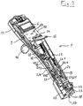
- the electronic manual dosing device 1 is an electronic hand dispenser. It has a bar-shaped housing 2 which is divided longitudinally into a front housing shell 3 and a rear housing shell 4.
- a dial 5 On the front of the housing 2 is located at the top of a dial 5 for selecting the respective operating mode.
- the dial 5 for example, the metering functions pipetting, dispensing and titration are adjustable.
- Including a display 6 is embedded in the front of the housing 2.
- rocker switch 7, 8 which serve to select various menu functions and setting parameters.
- the rocker switch 7, 8 are located on the left and right side of the housing electrical contacts 9, 10 for charging a battery of an electrical power supply 11.
- the battery is housed in the upper part of the housing 2.
- a release button 14 for triggering of suction and dispensing steps and for storing parameter settings.
- a throw-off button 15 In front of the release button 14 is a throw-off button 15 which engages in the downwardly fitting the flat front of the housing 2 bulge 13.
- the housing 2 has a first opening 17 through which a first receptacle 18 in the housing 2 for a syringe flange of a syringe barrel of a syringe is accessible from the outside.
- a first receptacle 18 in the housing 2 for a syringe flange of a syringe barrel of a syringe is accessible from the outside.
- a bell-shaped receiving body 19 located above the first receptacle 18 is a bell-shaped receiving body 19, in which a second receptacle 20 is arranged, which is accessible through a second opening 21 on the underside of the receiving body 19 for insertion of a piston rod end of a syringe plunger of the syringe.
- first receptacle 18 In the first receptacle 18 are first means for releasably holding the syringe flange to a stop 22 in the housing 2, which are designed as syringe gripping lever 23.
- the receiving body 19 has second means for releasable holding in the form of piston gripping levers 24, which serve to releasably hold the syringe plunger in the second receptacle 20.
- the attachment of syringe flange and syringe piston in the first and second receptacles 18, 20 by means of the first and second releasable holding means can be resolved by operating the Abwerfertaste 15 which acts via a gear 25 to the syringe gripping lever 23 and piston gripping lever 24.
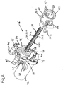
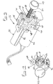
- the syringe plunger is displaceable by means of a metering drive 26.
- the metering drive 26 comprises a spindle drive 27, which has a threaded spindle 28 and a spindle nut 29.
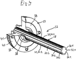
- the threaded spindle 28 has two longitudinally extending first flats 30.1, 30.2 on the two sides and in between two threaded portions 31.1, 31.2 of an external thread 31. According to Fig. 4 and 5 taper in cross section, the threaded portions 31.1, 31.2 in the radial direction to the outside.
- first flats 30.1, 30.2 are outward guide ribs 32.1, 32.2 before.
- Fig. 4 and 5 have the guide ribs 32.1, 32.2 at the outer end second flats 33.1, 33.2.
- they have guide portions 34.1, 34.2, 34.3, 34.4, whose distance from the central axis of the threaded spindle 28 corresponds to half the core diameter of an internal thread 35 of the spindle nut 29.
- Fig. 5 has the external thread 31 trapezoidal thread profiles 36.1, 36.2.
- the radially outer edges of the thread profiles 36.1, 36.2 are rounded.
- the transitions of the flanks 37.1, 37.2 of the thread profiles 36.1, 36.2 to the core of the threaded spindle 28 are rounded on both sides.
- the rounded by the first flats 30.1, 30.2 limited lateral edges of the thread profiles 36.1, 36.2.
- the outer edges of the guide ribs 32.1, 32.2 and the transitions of the guide ribs 32.1, 32.2 to the first flats 30.1, 30.2 are rounded.
- the threaded spindle 28 is injection molded so that the parting plane of the two halves of the injection mold falls into the second flats 33.1, 33.2.
- the rounding of the guide ribs 32.1, 32.2 and the thread profiles 36.1, 36.2 are advantageous for the filling of the injection mold and the removal of the molding from the injection mold.
- the rounding of the profiles 36.1, 36.2 and the guide portions 34.1, 34.2, 34.3, 34.4 are also advantageous for the friction and low-wear adjustment of the threaded spindle 28 in the spindle nut 29th
- the spindle nut 29 has a central hollow shaft 38, on whose inner circumference the internal thread 35 is formed.
- the internal thread 35 extends continuously over a first portion of the sleeve.
- the thread profile of the internal thread 35 is also trapezoidal, with the radially inner ends of the profile are rounded and the transitions between the flanks of the profile also.
- a circular disk 39 which is formed as a toothed belt wheel 40 with a toothing 41 on the circumference.
- the hollow shaft 38 projects from the annular disc 39 on both sides.
- the external thread 31 of the threaded spindle 28 and the internal thread 35 of the spindle nut 29 are matched to one another, so that the threaded spindle 28 can be screwed into the spindle nut 29.
- the metering drive 26 according to Fig. 3 an electric drive motor 42 which carries a further toothed belt wheel 44 on a motor shaft 43.
- the spindle nut 29 is rotatably mounted on the hollow shaft 38 in two bearing bushes 45, which is held in two parallel holding plates 46 of a holder 47 at a defined distance from each other and from the drive motor 42.
- the holder 47 has bearing eyes 48 for fixing in the housing 2.
- a toothed belt 49 is placed around to transmit the rotation of the motor shaft 43 to the spindle nut 29.
- the metering drive 26 comprises pin-shaped first guide elements 50.1, 50.2, which protrude in opposite directions from the receiving body 19 to the outside.
- the first guide elements 50.1, 50.2 interact with guide tracks between strip-shaped second guide elements 51.1, 51.2 on the inner sides of the housing shells 3, 4.
- the threaded spindle 28 is prevented from rotating in the housing 2 and the receiving body 19 is guided in the axial direction of the threaded spindle 28.
- the dosing drive 26 includes an electrical control device 52 arranged in the upper region of the housing.
- the control device 52, the electric drive motor 42 and the remaining electronic components of the dosing device are fed by the electric power supply 11.
- the threaded spindle 28 and the spindle nut 29 are made of plastics and / or metal. Preferably, high performance plastics and / or engineering plastics are used for this purpose.
- the threaded spindle 28 and the spindle nut 29 are each made of PEEK.
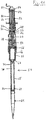
- the electronic manual dosing device 1 is an electronic handheld pipette. It has an upper housing part 53 in the form of a handle and a substantially cylindrical lower housing part 54.
- the upper housing part 53 contains a drive unit and the lower housing part 54 a displacement unit comprising a cylinder 55 and a piston 56 displaceable therein, which is displaceable by means of the drive unit.
- the upper housing part 53 has a substantially cylindrical body portion 57 and a box-shaped head portion 58, which forms an obtuse angle with the body portion 57.
- the head section has a dial 5 on the front side at the top for selecting the respective operating mode, for example pipetting, dispensing, pipetting and mixing, reverse pipetting, multiple recording, sequential dispensing.
- a display 6 is inserted into the front of the head portion 58.
- rocker button 59 for controlling the recording and dispensing of liquid and the setting of parameters available.
- keys 60 for selecting various menu functions and setting parameters.
- a Abwerfertaste 15 for controlling the ejection of pipette tips 61.
- the Abwereftaste 15 is connected to a Abwerferstange extending in the body portion 57 to the lower end thereof.
- the head portion 58 At the level of the display 6 are on the left and right side of the head portion 58 electrical contacts 9, 10 for charging a housed in the head portion 58 batteries of an electrical power supply 11.
- the battery is connected to a housed in the head portion 58 electrical control device 52.
- the electrical control device 52 is connected to the rocker switch 59 and the other buttons 60, a sensor for detecting the rotational position of the selector wheel 5 and a drive motor 42 of a metering drive 26.
- the body portion 57 has a cavity 62, in which the metering drive 26 is arranged at the top, which will be explained in more detail below.
- the body portion 57 has at the lower end a lower housing opening 63 through which the lower housing part 54 is inserted with its upper end in the cavity 62 of the body portion 57.
- the lower housing part 54 is releasably connected to the upper housing part 53 by means for releasably connecting the lower housing part 54 and the upper housing part 53.
- the means for releasably connecting comprise a latching connection with spring-loaded latching hook 64 of the lower housing part 54 which are latched in the cavity 62 behind locking edges of the upper housing part 53. The locking can be selectively canceled by moving a guided outside the lower housing part 54 Entrastungshülse 65.
- the lower housing part 54 has the cylinder 55 with the piston 56 displaceable longitudinally and sealingly guided therein.
- the cylinder 55 is formed as a bush ( liner ) which is held in a cylinder portion 66 of the housing base 54.
- the cylinder portion is connected at the bottom via a conical connecting portion 67 with a tube 68 having at the lower end a sealing seat 69, on which the pipette tip 61 is clamped.
- the tube 68 defines a communication channel 70 which connects a first hole 71 at the lower end of the cylinder 55 to a second hole 72 in the sealing seat 69 at the lower end of the tube 68.
- the connecting portion 67 and the tube 68 is adapted to the outer shape thereof ejector sleeve 72 for pushing the pipette tip 61 from the sealing seat 69 is pushed.
- the ejector sleeve 73 is connected at the top via detachable coupling means of ejector sleeve 73 and ejector rod to the ejector rod.
- the releasable coupling means consist in a simple case in a clamping fit of the lower end of the Abwerferstange in a bore in a lateral projection on the upper edge of the ejector sleeve 73rd
- the lower housing part 54 carries at the top a closure cap 74 whose cap jacket 75 is connected to the cylinder section 66 and which has a central upper housing opening 77 in a cap bottom 76.
- the piston 56 is connected to a piston rod 78 which carries a plate 79 above. Between plate 79 and upper edge of the cylinder 55, a coil spring 80 is arranged, which presses the plate 79 in an initial position on the underside of the cap bottom 76.
- Fig. 9 to 12 engages the threaded spindle 28 of the metering drive 26 with its lower end through the upper housing opening 77 through into the cap 74 and is located at the top of the plate 79 at.
- FIGS. 12 and 13 corresponds to the metering 26 largely the metering 26 of Fig. 3 so the comments too Fig. 3 Accordingly, for the provided with the same reference numerals of FIGS. 12 and 13 be valid.
- the plate 79 In the metering 26 of FIGS. 12 and 13 contacted the lower end of the threaded spindle 28, the plate 79 and is not connected to a bell-shaped receiving body 19.
- the guide cylinder 81 On the inner circumference, the guide cylinder 81 has two guide grooves 82 which extend in the longitudinal direction of the guide cylinder 81.
- the two guide grooves 82 are diametrically opposite each other.
- Fig. 10 and 13 carries the threaded spindle 28 at the upper end of a sleeve-shaped guide member 83 which has two outwardly projecting guide lugs 84 which engage in the guide grooves 82.
- the guide element 83 is firmly connected to the threaded spindle 28.
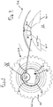
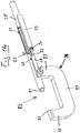
- Fig. 14 shows a micrometer 85, which is designed as a micrometer.
- a rigid bracket 86 has a base 87 and two bracket arms 88, 89.
- a circular disk-shaped first measuring jaw 90 is fixed, which has a plane first contact surface at its free end.
- a spindle nut 29 is attached on a second bail arm 89.
- the upper part of the spindle nut 29 is cut away in the drawing for better understanding.
- In an internal thread 35 of the spindle nut 29 engages a threaded spindle 28 with its external thread 31 and forms with this a spindle drive.
- the threaded spindle 28 is firmly connected on one side with a cylindrical second measuring jaw 91, which has a flat second contact surface at its free end.
- the spindle nut has on the outside on a longitudinally extending first scale 92 with a millimeter division.
- the threaded spindle 28 is connected to a measuring sleeve 93 via a friction clutch, not shown ("feeler slide").
- the upper part of the measuring sleeve 93 is cut away in the drawing for better understanding.
- the measuring sleeve 93 has a circumferentially extending second scale 94 with a hundredths of a millimeter division.
- the threaded spindle 28 and the spindle nut 29 are designed according to the invention a spindle drive 27.
- the micrometer 85 is inexpensive to produce, very light and provides accurate measurement results.
Abstract
Spindelantrieb umfassend - eine Gewindespindel mit einem Außengewinde, - eine Spindelmutter mit einem Innengewinde, das mit dem Außengewinde der Gewindespindel in Eingriff steht, dadurch gekennzeichnet, dass - das Außengewinde der Gewindespindel mehrere Gewindebereiche aufweist, die durch in Längsrichtung erstreckte erste Abflachungen an ihrem Umfang voneinander getrennt sind, und - die ersten Abflachungen Führungsbereiche aufweisen, die am Kerndurchmesser des Innengewindes der Spindelmutter anliegen.Spindle drive comprising a threaded spindle with an external thread, a spindle nut having an internal thread which engages with the external thread of the threaded spindle, characterized in that - The external thread of the threaded spindle has a plurality of threaded portions which are separated by longitudinally extending first flats at its periphery, and - The first flats have guide portions which bear against the core diameter of the internal thread of the spindle nut.
Description
Die Erfindung betrifft einen Spindelantrieb umfassend eine Gewindespindel und eine Spindelmutter, insbesondere für die Messtechnik, Stelltechnik und Antriebstechnik.The invention relates to a spindle drive comprising a threaded spindle and a spindle nut, in particular for metrology, positioning and drive technology.
Spindelantriebe werden in der Messtechnik insbesondere zum Messen von Längen oder Abständen verwendet. Ein Beispiel ist die Messschraube (ältere Bezeichnung: Mikrometerschraube, Mikrometer), die in Ausführung als Bügelmessschraube zur Bestimmung von Außenmaßen, als Innenmessschraube zur Bestimmung von inneren Abständen und als Tiefenmessschraube zur Tiefenmessung herangezogen wird. An optischen Geräten kommen Messschrauben zur Verschiebung von Messmarken zum Einsatz. Sie werden als Messokulare, Messschraubenokulare oder Okularmessschrauben bezeichnet.Spindle drives are used in metrology in particular for measuring lengths or distances. An example is the micrometer (formerly called micrometer screw, micrometer), which is used in the form of an external micrometer for the determination of external dimensions, as an internal micrometer for the determination of internal distances and as depth gauge for depth measurement. On optical devices, micrometers are used to move measuring marks. They are referred to as Messokulare, Meßschraubenokulare or ocular micrometers.
In der Stelltechnik werden Spindelantriebe insbesondere für Positionierungs- und Justierungsaufgaben eingesetzt. Ein weites Einsatzgebiet solcher Stelleinrichtungen oder Stellglieder ist die Steuerungs- und Regelungstechnik. Ferner werden Spindelantriebe in der Mikro- und Feinjustage verwendet. Des Weiteren werden Spindelantriebe zum Öffnen und Schließen von Gehäusen und Einstellen von anderen Geräteteilen eingesetzt. In der Gebäudetechnik kommen sie zum Öffnen und Schließen von Türen, Toren und Fenstern zum Einsatz.Spindle drives are used in positioning technology in particular for positioning and adjustment tasks. A wide field of application of such control devices or actuators is the control technology. Furthermore, spindle drives are used in micro and fine adjustment. Furthermore, spindle drives are used for opening and closing housings and adjusting other parts of the device. In building technology, they are used to open and close doors, gates and windows.
In der Dosiertechnik werden Spindelantriebe zum Einstellen der Dosiermenge verwendet. Bekannt sind Pipettiervorrichtungen mit einer Hubstange zum Antreiben eines Kolbens in einem Zylinder, um Flüssigkeit in eine Pipettenspitze oder Spritze einzusaugen und aus dieser auszustoßen. Die Pipettiervorrichtungen umfassen eine Einstelleinrichtung zum Einstellen des Dosiervolumens mit einer Spindelmutter und einer Gewindespindel, wobei eines dieser Bauteile feststeht und das andere schraubbar ist. Das schraubbare Bauteil weist einen Anschlag auf, der mit einem Gegenanschlag der Hubstange zusammenwirkt. Durch Einstellen des Anschlages wird der Hub der Hubstange begrenzt und das Dosiervolumen eingestellt.Spindle drives are used to set the dosing quantity in dosing technology. Are known pipetting with a lifting rod for driving a piston in a cylinder to suck liquid in a pipette tip or syringe and expel from this. The pipetting devices comprise an adjusting device for adjusting the metering volume with a spindle nut and a threaded spindle, wherein one of these components is fixed and the other is screwed. The screwable component has a stop, which with a counter-stop the lift rod cooperates. By adjusting the stop, the stroke of the lifting rod is limited and the dosing volume adjusted.
Auch in der Antriebstechnik gibt es vielfältige Anwendungen. Im Bereich der Automatisierungstechnik kommen Linearantriebe beispielsweise in XYZ- Übertragungssystemen und anderen Roboterarmen zum Einsatz. In der Werkzeugmaschinentechnik dienen sie beispielsweise der Verlagerung von Werkzeugschlitten. In der Dosiertechnik kommen Spindelantriebe zum Einsatz, um einen Kolben in einem Zylinder zu verlagern und hierdurch Flüssigkeit anzusaugen und auszustoßen.There are also many applications in drive technology. In automation technology, linear drives are used, for example, in XYZ transmission systems and other robot arms. In machine tool technology, they serve, for example, the displacement of tool slides. Spindle drives are used in dosing technology in order to displace a piston in a cylinder and thereby suck in and expel liquid.
Elektronische Dosiervorrichtungen zum Dosieren von Flüssigkeiten umfassend einen elektrischen Dosierantrieb mit Spindelantrieb und elektrischem Antriebsmotor werden insbesondere in wissenschaftlichen und industriellen Labors mit medizinischen, molekularbiologischen und pharmazeutischen Anwendungsgebieten eingesetzt. Bei Direktverdrängersystemen wird die Dosiervorrichtung mit einer austauschbaren Spritze gekoppelt. Der elektronische Dosierantrieb treibt einen Spritzenkolben in einem Spritzenzylinder der Spritze an. Bei Luftpolstersystemen umfasst die elektronische Dosiervorrichtung außer dem Dosierantrieb einen Zylinder und einen darin verlagerbaren, mit dem Dosierantrieb gekoppelten Kolben. Ferner weist sie einen Dichtsitz zum abdichtenden Festklemmen einer Pipettenspitze auf. Ein Loch im Dichtsitz ist über einen Kanal mit dem Zylinder verbunden.Electronic dosing devices for dosing liquids comprising an electric dosing drive with spindle drive and electric drive motor are used in particular in scientific and industrial laboratories with medical, molecular biological and pharmaceutical applications. In direct displacement systems, the metering device is coupled to a replaceable syringe. The electronic dosing drive drives a syringe plunger in a syringe barrel of the syringe. In air cushion systems, the electronic metering device comprises, in addition to the metering drive, a cylinder and a piston displaceable therein and coupled to the metering drive. It also has a sealing seat for sealingly clamping a pipette tip. A hole in the sealing seat is connected to the cylinder via a channel.
Elektronische Handdosiervorrichtungen sind vom Benutzer mit nur einer Hand tragbar und bedienbar. Direktverdrängersysteme werden auch als elektronische Dispenser oder Repetierpipetten bezeichnet. Luftpolstersysteme werden auch als Pipetten bezeichnet. Hierbei handelt es sich um Halbautomaten, da sie von Hand positioniert und bedient werden müssen, wobei der (Spritzen-)Kolben von einem elektrischen Antriebsmotor angetrieben wird.Electronic Handdosiervorrichtungen are user-friendly and with only one hand. Direct displacement systems are also referred to as electronic dispensers or repeating pipettes. Air cushion systems are also referred to as pipettes. These are semi-automatic because they must be manually positioned and operated with the (syringe) piston driven by an electric drive motor.
Ferner sind elektronische Dosiervorrichtungen in Dosierautomaten (LHS = Liquid Handling Stations) und Laborautomaten (WS = Work Stations) integriert. Diese weisen ein Dosierwerkzeug und einen Roboterarm zur Positionierung des Dosierwerkzeuges auf. Der Roboterarm ist z.B. ein XYZ-Übertragungssystem.Furthermore, electronic dosing devices are integrated in dosing machines (LHS = liquid handling stations) and laboratory machines (WS = work stations). These have a metering tool and a robot arm for positioning the metering tool. The robot arm is e.g. an XYZ transmission system.
Bei den vorstehenden Spindelantrieben bestehen Gewindespindel und Spindelmutter aus Metall.In the above spindle drives consist threaded spindle and spindle nut made of metal.
Nachteilig ist die aufwendige Fertigung der Gewindespindel mittels hochpräziser Drehmaschinen und Nachbearbeitung, z.B. durch Entgraten. Ferner kann es zu einem Schlagen der Gewindespindel kommen, wenn sie mit einem nicht geführten Ende weiter aus der Spindelmutter heraussteht. Der Spindelantrieb ist korrosionsanfällig. Durch Korrosion wird die Reibung und damit der Verschleiß erhöht sowie die Genauigkeit vermindert. Der Spindelantrieb benötigt Schmiermittel, welches Staub bindet, wodurch der Verschleiß erhöht und die Genauigkeit herabgesetzt wird. Überlast kann zu plastischer Verformung führen, die ebenfalls die Präzision des Spindelantriebs herabsetzt.A disadvantage is the complicated manufacture of the threaded spindle by means of high-precision lathes and post-processing, e.g. by deburring. Furthermore, it can come to a beating of the threaded spindle, if it protrudes with an uncontrolled end further from the spindle nut. The spindle drive is susceptible to corrosion. Corrosion increases friction and thus wear and reduces accuracy. The spindle drive needs lubricant that binds dust, which increases wear and reduces accuracy. Overload can lead to plastic deformation, which also reduces the precision of the spindle drive.
Dier
Die
Davon ausgehend liegt der Erfindung die Aufgabe zugrunde, einen einfacher herstellbaren und präzise arbeitenden Spindelantrieb zu schaffen.On this basis, the invention has for its object to provide a simpler to produce and precise working spindle drive.
Gemäß der Erfindung wird die Aufgabe durch einen Spindelantrieb mit den Merkmalen von Anspruch 1 gelöst. Vorteilhafte Ausgestaltungen des Spindelantriebs sind in Unteransprüchen angegeben.According to the invention the object is achieved by a spindle drive with the features of
Der erfindungsgemäße Spindelantrieb umfasst:
- eine Gewindespindel mit einem Außengewinde,
- eine Spindelmutter mit einem Innengewinde, das mit dem Außengewinde der Gewindespindel in Eingriff steht,
- das Außengewinde der Gewindespindel mehrere Gewindebereiche aufweist, die durch in Längsrichtung erstreckte erste Abflachungen an ihrem Umfang voneinander getrennt sind, und
- die ersten Abflachungen Führungsbereiche aufweisen, die am Kerndurchmesser des Innengewindes der Spindelmutter anliegen.
- a threaded spindle with an external thread,
- a spindle nut having an internal thread which engages with the external thread of the threaded spindle,
- the external thread of the threaded spindle has a plurality of threaded portions which are separated by longitudinally extending first flats at their periphery, and
- the first flats have guide portions which abut the core diameter of the internal thread of the spindle nut.
Erfindungsgemäß weist der Spindelantrieb eine Gewindespindel auf, die in mehrere Gewindebereiche und mehrere Führungsbereiche unterteilt ist. In Umfangsrichtung ist auf beiden Seiten jedes Führungsbereiches jeweils ein Gewindebereich und auf beiden Seiten jedes Gewindebereichs jeweils ein Führungsbereich angeordnet. Die Gewindebereiche greifen in das Innengewinde der Spindelmutter ein, wodurch die Verlagerung der Gewindespindel beim Drehen gewährleistet ist. Die Führungsbereiche liegen am Kerndurchmesser des Innengewindes der Spindelmutter an, so dass sie in der Spindelmutter geführt sind. Infolgedessen ist die Spindelmutter gleichzeitig eine Führungsbuchse für die Gewindespindel. Auf zusätzliche Bauteile zum Führen der Gewindespindel kann verzichtet werden und Platz zum Unterbringen zusätzlicher Bauteile wird eingespart. Deshalb ist auch bei beengten Platzverhältnissen eine verbesserte Führung der Gewindespindel möglich. Der Spindelantrieb ist besonders präzise, weil die Gewindespindel in der Spindelmutter geführt ist.According to the invention, the spindle drive has a threaded spindle which is divided into a plurality of threaded regions and a plurality of guide regions. In the circumferential direction, a guide portion is disposed on both sides of each guide portion, and a guide portion is disposed on both sides of each threaded portion. The threaded areas engage in the internal thread of the spindle nut, whereby the displacement of the threaded spindle is ensured during rotation. The guide areas are applied to the core diameter of the internal thread of the spindle nut, so that they are guided in the spindle nut. As a result, the spindle nut is at the same time a guide bush for the threaded spindle. Additional components for guiding the threaded spindle can be dispensed with and space for accommodating additional components is saved. Therefore, an improved guidance of the threaded spindle is possible even in confined spaces. The spindle drive is particularly precise, because the threaded spindle is guided in the spindle nut.
Gemäß einer Ausführungsart der Erfindung ist die Gewindespindel ein Spritzgießteil. Bei dieser Ausführungsart ist die Gewindespindel durch Spritzgießen hergestellt. Die Unterteilung der Gewindespindel in Gewindebereiche und Führungsbereiche ist vorteilhaft für die Herstellung der Gewindespindel durch Spritzgießen, da die Unterteilung des Außengewindes eine spritzgusstechnische Herstellung mittels eines Spritzgießwerkzeuges mit mehreren Formteilen ermöglicht. Die Trennebene des Spritzgießwerkzeugs kann so gelegt werden, dass sie in die Führungsbereiche fällt. Hierdurch können Hinterschnitte in den Gewindebereichen vermieden oder stark reduziert werden, welche die Entformung der Gewindespindel aus dem Spritzgießwerkzeug behindern und die Präzision beeinträchtigen. Die Kosten für die Herstellung der Gewindespindel können reduziert und eine Nachbearbeitung eingespart werden.According to one embodiment of the invention, the threaded spindle is an injection-molded part. In this embodiment, the threaded spindle is produced by injection molding. The subdivision of the threaded spindle in threaded areas and guide areas is advantageous for the production of the threaded spindle by injection molding, since the subdivision of the external thread allows injection molding production by means of an injection mold with multiple moldings. The parting line of the injection mold can be placed so that it falls into the guide areas. As a result, undercuts in the threaded areas can be avoided or greatly reduced, which hinder the removal of the threaded spindle from the injection mold and affect the precision. The costs for the production of the threaded spindle can be reduced and a reworking can be saved.
Gemäß einer weiteren Ausführungsart besteht die Gewindespindel aus einem ersten Kunststoff. Die Gewindespindel aus Kunststoff hat verbesserte Gleiteigenschaften. Hierdurch wird der Verschleiß reduziert und der Verlust an Präzision verringert. Auch die Korrosionsfestigkeit und chemische Beständigkeit der Gewindespindel aus Kunststoff verringert den Verschleiß und den damit verbundenen Verlust an Präzision. Zudem stehen Kunststoffe mit verbesserten Gleiteigenschaften zur Verfügung, so dass Schmiermittel entfallen kann, welches Staub bindet und Verschleiß sowie Verlust an Präzision verursacht. Es ist aber auch möglich, die Gleiteigenschaften durch Applizieren von geringen Mengen von Schmiermittel noch zu verbessern. Durch die verringerte Reibung zwischen Gewindespindel und Spindelmutter wird die Stromaufnahme des Motors gesenkt und die Akkulaufzeit erhöht. Schließlich wird durch die Gewindespindel aus Kunststoff das Gewicht des Spindelantriebs verringert. Kunststoffe mit hoher mechanischer Belastbarkeit stehen zur Verfügung. Da diese Kunststoffe nur eine geringe oder gar keine plastische Verformbarkeit haben, sondern bei Überlastung brechen, führt eine Überlastung nicht zu einer Verschlechterung der Präzision, sondern zum Bruch, so dass die Notwendigkeit einer Reparatur leicht erkennbar ist. Gemäß einer bevorzugten Ausführungsart ist die Gewindespindel aus Kunststoff ein Spritzgießteil. Gemäß einer anderen Ausführungsart ist die Gewindespindel aus Kunststoff ein Sinterteil, d.h. die Gewindespindel ist durch Sintern von Kunststoffpartikeln hergestellt. Gemäß einer anderen Ausführungsart ist die Gewindespindel aus Kunststoff durch Schneiden, Walzen und/oder Fräsen hergestellt. Gemäß einer anderen Ausführungsart ist die Gewindespindel aus Kunststoff durch 3D-Drucken hergestellt.According to a further embodiment, the threaded spindle consists of a first plastic. The threaded spindle made of plastic has improved sliding properties. This reduces wear and reduces the loss of precision. The corrosion resistance and chemical resistance of the threaded spindle made of plastic reduces wear and the associated loss of precision. In addition, plastics with improved sliding properties are available so that lubricant can be eliminated, which binds dust and causes wear and loss of precision. But it is also possible to improve the sliding properties by applying small amounts of lubricant yet. Due to the reduced friction between the threaded spindle and the spindle nut is The power consumption of the engine lowered and the battery life increased. Finally, the weight of the spindle drive is reduced by the threaded spindle made of plastic. Plastics with high mechanical load capacity are available. Since these plastics have little or no plastic deformability, but break under overload, overloading does not lead to deterioration of precision but to breakage, so that the need for repair is easily recognized. According to a preferred embodiment, the threaded spindle made of plastic is an injection molded part. According to another embodiment, the threaded spindle made of plastic is a sintered part, that is, the threaded spindle is produced by sintering of plastic particles. According to another embodiment, the threaded spindle made of plastic by cutting, rolling and / or milling. According to another embodiment, the threaded spindle made of plastic is produced by 3D printing.
Gemäß einer weiteren Ausführungsart besteht die Gewindespindel aus Metall. Gemäß einer weiteren Ausführungsart ist die Gewindespindel aus Metall durch Schneiden, Walzen und/oder Fräsen hergestellt. Gemäß einer weiteren Ausführungsart ist die Gewindespindel aus Metall durch Sintern von Metallpulver hergestellt.According to another embodiment, the threaded spindle is made of metal. According to another embodiment, the threaded spindle is made of metal by cutting, rolling and / or milling. According to a further embodiment, the threaded spindle is made of metal by sintering metal powder.
Gemäß einer weiteren Ausführungsart ist die Gewindespindel MIM (Metal Injection Molding) hergestellt. Dabei wird ein Metallpulver mit einer Kunststoffmatrix vermengt und spritzgegossen. Das Ergebnis ist eine Gewindespindel, die vollständig oder im Wesentlichen aus Metall besteht, weil der Kunststoff beim Herstellungsprozess entfernt wird.According to a further embodiment, the threaded spindle MIM ( Metal Injection Molding ) is produced. Here, a metal powder is mixed with a plastic matrix and injection-molded. The result is a threaded spindle made entirely or essentially of metal because the plastic is removed during the manufacturing process.
Die vorteilhaften Wirkungen der Herstellung der Gewindespindel durch Spritzgießen kommen sowohl einer durch Spritzgießen hergestellten Gewindespindel aus Kunststoff als auch der durch MIM hergestellten Gewindespindel zu.The advantageous effects of the production of the threaded spindle by injection molding come both to a plastic threaded spindle produced by injection molding and to the threaded spindle produced by MIM.
Der Spindelantrieb eignet sich insbesondere für Einsatzfälle, in denen es auf Präzision, Laufruhe und geringes Gewicht des Antriebes ankommt.The spindle drive is particularly suitable for applications in which it depends on precision, smoothness and low weight of the drive.
Gemäß einer bevorzugten Ausführungsart der Erfindung ist zwischen den Führungsbereichen und dem Kerndurchmesser des Innengewindes eine Spielpassung vorhanden. Hierbei ist der nominale Kerndurchmesser des Innengewindes gleich dem nominalen Durchmesser der Gewindespindel an den Führungsbereichen. Der nominale Durchmesser an den Führungsbereichen ist der Durchmesser des kleinsten die Führungsbereiche berührenden und diese vollständig umhüllenden Kreises. Die Toleranzen der beiden Durchmesser sind so gewählt, dass eine Spielpassung vorliegt. Beispielsweise ist bei einem nominalen Durchmesser von 3,25 mm für den Kerndurchmesser eine Toleranz H11 gewählt, die eine Abweichung von 0 bis + 75 µm vom Nominaldurchmesser zulässt. Ferner ist für den Außendurchmesser der Führungsbereiche eine Toleranz d9 gewählt, die eine Abweichung vom Nominaldurchmesser von -30 µm bis -60 µm zulässt. Damit beträgt das Spiel zwischen Innengewinde und Führungsrippen minimal 30 µm und maximal 135 µm.According to a preferred embodiment of the invention, there is a clearance fit between the guide portions and the core diameter of the internal thread. Here, the nominal core diameter of the internal thread is equal to the nominal diameter of the threaded spindle at the guide areas. The nominal diameter at the guide areas is the diameter of the smallest circle touching and fully enveloping the guide areas. The tolerances of the two diameters are chosen so that there is a clearance fit. For example, with a nominal diameter of 3.25 mm for the core diameter, a tolerance H11 is chosen that allows a deviation of 0 to + 75 μm from the nominal diameter. Furthermore, a tolerance d9 is selected for the outer diameter of the guide regions, which allows a deviation from the nominal diameter of -30 microns to -60 microns. Thus, the clearance between internal thread and guide ribs minimally 30 microns and a maximum of 135 microns.
Das Spiel der Spielpassung beträgt gemäß einer bevorzugten Ausführungsart maximal 150 µm und minimal 0 µm, weiterhin vorzugsweise maximal 135 µm und minimal 30 µm.The game of clearance fit is according to a preferred embodiment, a maximum of 150 microns and a minimum of 0 microns, more preferably at most 135 microns and a minimum of 30 microns.
Gemäß einer weiteren Ausführungsart tragen die Abflachungen Führungsrippen, die an den äußeren Enden die Führungsbereiche aufweisen. Hierdurch wird eine besonders reibungsarme Führung der Gewindespindel in der Spindelmutter erreicht. Zudem sind Führungsrippen vorteilhaft für die Herstellung der Gewindespindel durch Spritzgießen, weil die Trennebene des Spritzgießwerkzeuges in die Ebene der Führungsrippen gelegt werden kann.According to a further embodiment, the flats carry guide ribs which have the guide areas at the outer ends. As a result, a particularly low-friction guidance of the threaded spindle is achieved in the spindle nut. In addition, guide ribs are advantageous for the production of the threaded spindle by injection molding, because the parting plane of the injection mold can be placed in the plane of the guide ribs.
Gemäß einer bevorzugten Ausführungsart hat die Gewindespindel nur zwei einander diametral gegenüberliegende erste Abflachungen, in die die Trennebene von zwei Werkzeughälften eines Spritzgießwerkzeuges gelegt werden kann. Gemäß einer weiteren Ausführungsart sind nur zwei einander diametral gegenüberliegende Führungsrippen vorhanden. Dies ermöglicht ein verhältnismäßig einfaches Spritzgießwerkzeug bei leichter Entformbarkeit und hoher Maßhaltigkeit.According to a preferred embodiment, the threaded spindle has only two diametrically opposite first flats into which the parting plane of two Tool halves of an injection mold can be placed. According to another embodiment, only two diametrically opposed guide ribs are present. This allows a relatively simple injection mold with easy demolding and high dimensional accuracy.
Gemäß einer weiteren Ausführungsart haben die Führungsrippen jeweils an den Enden eine zweite Abflachung und angrenzend an den beiden seitlichen Rändern der zweiten Abflachung Führungsbereiche in einem Abstand von der Mittelachse der Gewindespindel entsprechend dem halben Kerndurchmesser der Spindelmutter. Bei dieser Ausführungsart werden die Führungsrippen jeweils an den Führungsbereichen beidseitig der zweiten Abflachungen geführt. Dies hat den Vorteil, dass beim Spritzgießen der Gewindespindel an den zweiten Abflachungen erzeugte Entformungsgrate nicht in Kontakt mit der Spindelmutter kommen und ein präzises Führen der Gewindespindel in der Spindelmutter verhindern. Grundsätzlich ist es aber auch möglich, die Gewindespindel an den äußeren Enden der Führungsrippen dort zu führen, wo sich bei der Herstellung die Trennebene des Spritzgießwerkzeugs befindet. Entformungsgrate können durch präzise Herstellung des Spritzgießwerkzeugs vermieden bzw. durch Nachbearbeitung entfernt werden.According to a further embodiment, the guide ribs each have at the ends a second flattening and adjacent to the two lateral edges of the second flattening guide areas at a distance from the central axis of the threaded spindle corresponding to half the core diameter of the spindle nut. In this embodiment, the guide ribs are each guided on the guide areas on both sides of the second flats. This has the advantage that demolding burrs generated during injection molding of the threaded spindle on the second flats do not come into contact with the spindle nut and prevent precise guiding of the threaded spindle in the spindle nut. In principle, however, it is also possible to guide the threaded spindle at the outer ends of the guide ribs where the parting plane of the injection mold is located during production. Entformungsgrate can be avoided by precise production of the injection mold or removed by reworking.
Gemäß einer weiteren Ausführungsart sind die ersten Abflachungen ebene Flächen und/oder sind die zweiten Abflachungen ebene Flächen. Gemäß einer bevorzugten Ausführungsart stehen von durch ebene Flächen gebildeten ersten Abflachungen Führungsrippen nach außen vor. Die Bereiche einer ersten Abflachung in Form ebener Flächen, die auf verschiedenen Seiten derselben Führungsrippe angeordnet sind, können parallel oder abgewinkelt zueinander ausgerichtet sein.According to a further embodiment, the first flats are flat surfaces and / or the second flats are flat surfaces. According to a preferred embodiment, guide ribs project outwardly from first flats formed by flat surfaces. The regions of a first flattening in the form of flat surfaces, which are arranged on different sides of the same guide rib, can be aligned parallel or angled to each other.
Gemäß einer alternativen Ausführungsart sind die ersten Abflachungen nach außen gekrümmt und/oder sind die zweiten Abflachungen nach außen gekrümmt. Die Krümmungsradien der ersten Abflachungen sind größer als der halbe Kerndurchmesser des Innengewindes der Spindelmutter oder diesem gleich und/oder die Krümmungsradien der zweiten Abflachungen sind größer als der halbe Kerndurchmesser des Innengewindes der Spindelmutter.According to an alternative embodiment, the first flats are curved outwards and / or the second flattenings are curved outwards. The radii of curvature of the first flats are greater than half the core diameter of the internal thread of the spindle nut or the same and / or the Curvature radii of the second flats are greater than half the core diameter of the internal thread of the spindle nut.
Gemäß einer alternativen Ausführungsart sind die Führungsbereiche zugleich die nach außen gekrümmten ersten Abflachungen oder Teilbereiche davon. Bei dieser Ausführungsart tragen die ersten Abflachungen keine Führungsrippen. Die ersten Abflachungen können zusätzlich mit zweiten Abflachungen versehen sein, wobei der Krümmungsradius der zweiten Abflachungen größer ist als der halbe Kerndurchmesser der Spindelmutter. Beim Spritzgießen in den zweiten Abflachungen erzeugte Entformungsgrate kommen nicht in Kontakt mit der Spindelmutter. Alternativ werden Entformungsgrate durch präzise Herstellung des Spritzgießwerkzeugs vermieden oder durch Nachbearbeitung entfernt.According to an alternative embodiment, the guide areas are at the same time the outwardly curved first flats or partial areas thereof. In this embodiment, the first flats do not carry guide ribs. The first flats may additionally be provided with second flats, wherein the radius of curvature of the second flats is greater than half the core diameter of the spindle nut. Deformation burrs generated during injection molding in the second flats do not come into contact with the spindle nut. Alternatively, demolding burrs are avoided by precise production of the injection mold or removed by post-processing.
Gemäß einer weiteren Ausführungsart ist das Außengewinde und das Innengewinde ein Trapezgewinde oder ein Spitzgewinde oder ein Rundgewinde oder ein Sägengewinde.According to a further embodiment, the external thread and the internal thread is a trapezoid thread or a pointed thread or a round thread or a saw thread.
Gemäß einer weiteren Ausführungsart verjüngen sich die Gewindebereiche des Außengewindes zwischen den ersten Abflachungen in radialer Richtung nach außen. Dies ist vorteilhaft für die Entformung der Gewindespindel aus einem Spritzgießwerkzeug.According to a further embodiment, the threaded portions of the external thread taper outwardly between the first flats in the radial direction. This is advantageous for the removal of the threaded spindle from an injection mold.
Gemäß einer weiteren Ausführungsart sind die äußeren längsseitigen Ränder der Führungsrippen und/oder die Übergänge von den Führungsrippen zu den ersten Abflachungen gerundet. Dies ist vorteilhaft für die Entformung aus dem Spritzgießwerkzeug. Die verrundeten längsseitigen Ränder der Führungsrippen reduzieren die Reibung der Gewindespindel in der Spindelmutter.According to a further embodiment, the outer longitudinal edges of the guide ribs and / or the transitions from the guide ribs to the first flat surfaces are rounded. This is advantageous for removal from the injection mold. The rounded longitudinal edges of the guide ribs reduce the friction of the threaded spindle in the spindle nut.
Gemäß einer weiteren Ausführungsart sind die von den Abflachungen begrenzten seitlichen Ränder der Gewindeprofile verrundet. Hierdurch wird das reibungsarme Gleiten der Gewindespindel in der Spindelmutter gefördert und die Abnutzung verringert. Auch ist dies vorteilhaft für die Entformung aus dem Spritzgießwerkzeug.According to another embodiment, the lateral edges of the thread profiles bounded by the flattened portions are rounded. This will reduce the friction Sliding the lead screw supported in the spindle nut and reduces wear. This is also advantageous for removal from the injection mold.
Gemäß einer weiteren Ausführungsart sind die Übergänge der Flanken der Gewindeprofile zum Kern der Gewindespindel und/oder die in radialer Richtung äußeren Ränder der Gewindeprofile verrundet. Hierdurch wird das reibungsarme Gleiten der Gewindespindel in der Spindelmutter gefördert und die Abnutzung verringert. Auch ist dies vorteilhaft für die Entformung aus dem Spritzgießwerkzeug.According to a further embodiment, the transitions of the flanks of the thread profiles to the core of the threaded spindle and / or the radially outer edges of the thread profiles are rounded. As a result, the low-friction sliding of the threaded spindle is supported in the spindle nut and reduces wear. This is also advantageous for removal from the injection mold.
Gemäß einer weiteren Ausführungsart ist die Spindelmutter aus einem zweiten Kunststoff und/oder aus einem Metall hergestellt. Die Herstellung der Spindelmutter aus mindestens einem Kunststoff oder aus mindestens einem anderen spritzgießfähigen Material kann durch Spritzgießen erfolgen. Hierbei kann das Spritzgießwerkzeug einen entsprechenden Werkzeugkern zur Erzeugung des Innengewindes der Spindelmutter aufweisen. Ferner kann die Herstellung der Spindelmutter aus Kunststoff durch Sintern, Schneiden, Walzen und/oder Fräsen oder 3D-Druck erfolgen. Die Herstellung der Spindelmutter aus Metall kann durch Gewindeschneiden, Gewindeformen oder Gewindefräsen, durch MIM oder durch Sintern von Metallpulver erfolgen.According to a further embodiment, the spindle nut is made of a second plastic and / or of a metal. The production of the spindle nut from at least one plastic or from at least one other injection-moldable material can be done by injection molding. Here, the injection mold may have a corresponding tool core for generating the internal thread of the spindle nut. Furthermore, the production of the spindle nut made of plastic by sintering, cutting, rolling and / or milling or 3D printing done. The production of the spindle nut made of metal can be done by thread cutting, thread forming or thread milling, by MIM or by sintering metal powder.
Gemäß einer weiteren Ausführungsart ist der erste Kunststoff ein Hochleistungskunststoff oder ein technischer Kunststoff.According to a further embodiment, the first plastic is a high-performance plastic or a technical plastic.
Gemäß einer weiteren Ausführungsart ist der erste Kunststoff ausgewählt aus mindestens einem der nachfolgenden Hochleistungskunststoffe: PEEK, PPS, LCP, PPA, PEI, PES, PPSU, PSU, PC-HT. Gemäß einer weiteren Ausführungsart ist der erste Kunststoff ausgewählt aus mindestens einem der nachfolgenden technischen Kunststoffe: PA, ABS. Die Gewindespindel kann ausschließlich aus einem der vorerwähnten Kunststoffe hergestellt werden oder im Mehrkomponenten-Spritzgießverfahren aus einer Kombination von mehreren der vorerwähnten Kunststoffe.According to a further embodiment, the first plastic is selected from at least one of the following high-performance plastics: PEEK, PPS, LCP, PPA, PEI, PES, PPSU, PSU, PC-HT. According to another embodiment, the first plastic is selected from at least one of the following engineering plastics: PA, ABS. The threaded spindle can be made exclusively of one of the aforementioned plastics or in multi-component injection molding of a combination of several of the aforementioned plastics.
Gemäß einer weiteren Ausführungsart ist der zweite Kunststoff ein Hochleistungskunststoff oder ein technischer Kunststoff.According to another embodiment, the second plastic is a high-performance plastic or a technical plastic.
Gemäß einer weiteren Ausführungsart ist der zweite Kunststoff ausgewählt aus mindestens einem der nachfolgenden Hochleistungskunststoffe: PEEK, PPS, LCP, PPA, PEI, PES, PPSU, PSU, PC-HT. Gemäß einer weiteren Ausführungsart ist der zweite Kunststoff ausgewählt aus mindestens einem der technischen Kunststoffe: PA, ABS. Die Spindelmutter kann im Einkomponenten-Spritzgießverfahren aus nur einem der vorerwähnten Kunststoffe oder im Mehrkomponenten-Spritzgießverfahren aus mehreren der vorerwähnten Kunststoffe hergestellt werden.According to a further embodiment, the second plastic is selected from at least one of the following high performance plastics: PEEK, PPS, LCP, PPA, PEI, PES, PPSU, PSU, PC-HT. According to another embodiment, the second plastic is selected from at least one of the engineering plastics: PA, ABS. The spindle nut can be made in one-component injection molding of only one of the aforementioned plastics or in multi-component injection molding of several of the aforementioned plastics.
Gemäß einer bevorzugten Ausführungsart sind der erste Kunststoff und der zweite Kunststoff Hochleistungskunststoffe.According to a preferred embodiment, the first plastic and the second plastic are high-performance plastics.
Gemäß einer weiteren Ausführungsart sind die Gewindespindel und die Spindelmutter aus demselben Kunststoffmaterial hergestellt. Gemäß einer weiteren Ausführungsart sind Gewindespindel und Spindelmutter aus demselben Kunststoffmaterial hergestellt, wobei jedoch verschiedene Varianten der Kunststoffarten verwendet werden. Gemäß einer weiteren Ausführungsart sind Gewindespindel und Spindelmutter aus demselben Kunststoffmaterial hergestellt, die sich beispielsweise hinsichtlich der Zugabe von Füllstoffen oder Zuschlagsstoffen unterscheiden.According to another embodiment, the threaded spindle and the spindle nut are made of the same plastic material. According to another embodiment, threaded spindle and spindle nut are made of the same plastic material, but different variants of the types of plastics are used. According to another embodiment, threaded spindle and spindle nut are made of the same plastic material, which differ, for example, with regard to the addition of fillers or additives.
Gemäß einer bevorzugten Ausführungsart sind Mittel zum linearen Führen der Gewindespindel in Längsrichtung der Gewindespindel und Mittel zum Antreiben der Spindelmutter in Drehbewegung vorhanden. Bei dieser Ausführungsart wird die Spindelmutter in Drehbewegung versetzt und die Gewindespindel linear verlagert. Gemäß einer alternativen Ausführungsart sind Mittel zum Führen der Spindelmutter in Längsrichtung der Gewindespindel und Mittel zum Drehen der Gewindespindel vorhanden. Bei dieser Ausführungsart wird die Gewindespindel in Drehbewegung versetzt und hierdurch die Spindelmutter linear verlagert.According to a preferred embodiment, means are provided for linearly guiding the threaded spindle in the longitudinal direction of the threaded spindle and means for driving the spindle nut in rotational movement. In this embodiment, the spindle nut is set in rotary motion and the threaded spindle is displaced linearly. According to an alternative embodiment, means for guiding the spindle nut in the longitudinal direction of the threaded spindle and means for rotating the threaded spindle available. In this embodiment, the threaded spindle is set in rotary motion and thereby the spindle nut linearly displaced.
Gemäß einer weiteren Ausführungsart sind die Mittel zum linearen Führen mindestens ein mit der Gewindespindel oder der Spindelmutter verbundener Führungszapfen oder anderes erstes Führungselement und mindestens eine zur Gewindespindel parallele Führungsnut, in die der Führungszapfen eingreift oder anderes zweites Führungselement. Gemäß einer weiteren Ausführungsart sind die Mittel zum Drehen ein elektrischer Antriebsmotor, dessen Motorwelle mit der Gewindespindel oder der Spindelmutter gekoppelt ist. Gemäß einer weiteren Ausführungsart ist die Gewindespindel oder die Spindelmutter fest mit der Motorwelle verbunden oder über ein Zugmittelgetriebe, Zahnradgetriebe oder anderes Getriebe mit der Motorwelle oder der Spindelmutter gekoppelt.According to a further embodiment, the means for linear guiding at least one connected to the threaded spindle or the spindle nut guide pin or other first guide element and at least one parallel to the threaded spindle guide groove, in which engages the guide pin or other second guide element. According to another embodiment, the means for rotating an electric drive motor whose motor shaft is coupled to the threaded spindle or the spindle nut. According to a further embodiment, the threaded spindle or the spindle nut is fixedly connected to the motor shaft or coupled via a traction mechanism, gear transmission or other gear with the motor shaft or the spindle nut.
Gemäß einer weiteren Ausführungsart umfasst der Spindelantrieb eine tragende Struktur, ist das zweite Führungselement fest mit der tragenden Struktur verbunden und ist der elektrische Antriebsmotor an der tragenden Struktur befestigt. Der Antriebsmotor verlagert die Gewindespindel oder die Spindelmutter entlang des zweiten Führungselements bezüglich der tragenden Struktur. Die tragende Struktur kann jegliche Struktur sein, die zum Befestigen von zweitem Führungselement und Antriebsmotor in definierten Positionen in Bezug aufeinander geeignet ist. Gemäß einer weiteren Ausführungsart besteht die tragende Struktur aus einem einzigen oder aus mehreren Bauteilen. Gemäß einer weiteren Ausführungsart ist die tragende Struktur ein Gehäuse und/oder ein Rahmen (Chassis) und/oder ein Träger.According to a further embodiment, the spindle drive comprises a supporting structure, the second guide element is fixedly connected to the supporting structure and the electric drive motor is fastened to the supporting structure. The drive motor displaces the threaded spindle or the spindle nut along the second guide element with respect to the supporting structure. The supporting structure may be any structure suitable for securing the second guide member and drive motor in defined positions with respect to each other. According to a further embodiment, the supporting structure consists of a single or multiple components. According to a further embodiment, the supporting structure is a housing and / or a frame (chassis) and / or a carrier.
Ferner betrifft die Erfindung eine Dosiervorrichtung umfassend einen erfindungsgemäßen Spindelantrieb. Gemäß einer bevorzugten Ausführungsart ist der Spindelantrieb gemäß einem der Ansprüche 1 bis 14 ausgebildet.Furthermore, the invention relates to a metering device comprising a spindle drive according to the invention. According to a preferred embodiment of the spindle drive according to one of
Gemäß einer Ausführungsart der Dosiervorrichtung umfasst eine Einstelleinrichtung zum Einstellen des Dosiervolumens den Spindelantrieb. Gemäß einer weiteren Ausführungsart ist die Gewindespindel oder die Spindelmutter fest mit einem Anschlag verbunden und weist eine mit einem Kolben in einem Zylinder gekoppelte Hubstange einen Gegenanschlag auf, der beim Verlagern der Hubstange auf den Anschlag trifft, wobei der Hub der Hubstange durch die Position des Anschlags begrenzt ist, die mittels des Spindelantriebs einstellbar ist. Die Dosiervorrichtung mit einstellbarem Dosiervolumen ist gemäß weiterer Ausführungsarten ein Direktverdrängersystem oder ein Luftpolstersystem.According to one embodiment of the metering device, an adjusting device for adjusting the metering volume comprises the spindle drive. According to a further embodiment, the threaded spindle or the spindle nut is firmly connected to a stop and has a coupled with a piston in a cylinder lifting rod on a counter-stop, which meets when displacing the lifting rod on the stop, wherein the stroke of the lifting rod by the position of the stop is limited, which is adjustable by means of the spindle drive. The metering device with adjustable metering volume is according to further embodiments, a direct displacement system or an air cushion system.
Eine weitere Ausführungsart der Dosiervorrichtung ist eine elektronische Dosiervorrichtung umfassend einen mit der Gewindespindel gekoppelten elektrischen Antriebsmotor, eine fest an der tragenden Struktur angeordnete erste Aufnahme für einen Spritzenflansch eines Spritzenzylinders einer Spritze und einen Aufnahmekörper mit einer zweiten Aufnahme für ein Kolbenstangenende eines Spritzenkolbens der Spritze, wobei der Aufnahmekörper fest mit einem unteren Ende der Gewindespindel verbunden ist.A further embodiment of the metering device is an electronic metering device comprising an electric drive motor coupled to the threaded spindle, a first receptacle for a syringe flange of a syringe barrel of a syringe fixed to the supporting structure and a receiving body with a second receptacle for a piston rod end of a syringe plunger of the syringe the receiving body is fixedly connected to a lower end of the threaded spindle.
Diese elektronische Dosiervorrichtung ist ein Direktverdrängersystem.This electronic dosing device is a direct displacement system.
Gemäß einer weiteren Ausführungsart umfasst die elektronische Dosiervorrichtung erste Mittel zum lösbaren Halten des Spritzenflansches in der ersten Aufnahme und zweite Mittel zum lösbaren Halten des Kolbenstangenendes in der zweiten Aufnahme. Die erste Aufnahme und die zweite Aufnahme sowie die ersten Mittel zum lösbaren Halten und die zweite Mittel zum lösbaren Halten sind vorzugsweise so ausgebildet, wie in der
Eine alternative Ausführungsart ist eine elektronische Dosiervorrichtung umfassend einen mit der Gewindespindel gekoppelten elektrischen Antriebsmotor, mindestens einen Zylinder, in dem ein Kolben verschiebbar angeordnet ist, der mit dem unteren Ende der Gewindespindel gekoppelt ist, mindestens einen Dichtsitz zum abdichtenden Festklemmen einer Pipettenspitze und mindestens einen Verbindungskanal, der ein Loch im Dichtsitz mit dem Zylinder verbindet.An alternative embodiment is an electronic dosing device comprising an electric drive motor coupled to the threaded spindle, at least a cylinder in which a piston is slidably mounted, which is coupled to the lower end of the threaded spindle, at least one sealing seat for sealingly clamping a pipette tip and at least one connecting channel which connects a hole in the sealing seat with the cylinder.
Diese Dosiervorrichtung ist ein Luftpolstersystem.This metering device is an air cushioning system.
Gemäß einer Ausführungsart ist der Dichtsitz die Mantelfläche eines konischen und/oder zylindrischen Ansatzes und ist das Loch in der Stirnfläche des Ansatzes vorhanden.According to one embodiment, the sealing seat is the lateral surface of a conical and / or cylindrical projection and the hole is present in the end face of the projection.
Gemäß einer weiteren Ausführungsart weist die elektronische Dosiervorrichtung nur einen einzigen Zylinder mit einem darin verschiebbaren Kolben auf. Hierbei handelt es sich um eine Einkanaldosiervorrichtung. Gemäß einer anderen Ausführungsart weist die elektronische Dosiervorrichtung mehrere parallele Zylinder mit einem darin verschieblichen Kolben sowie mehrere Dichtsitze auf, die jeweils über einen Verbindungskanal mit einem Zylinder verbunden sind. Hierbei handelt es sich um eine Mehrkanaldosiervorrichtung.According to a further embodiment, the electronic metering device has only a single cylinder with a piston displaceable therein. This is a single-channel dosing device. According to another embodiment, the electronic metering device has a plurality of parallel cylinders with a piston displaceable therein and a plurality of sealing seats, which are each connected via a connecting channel with a cylinder. This is a multi-channel dosing device.
Gemäß einer weiteren Ausführungsart ist die Dosiervorrichtung eine Handdosiervorrichtung. Gemäß einer weiteren Ausführungsart ist die tragende Struktur der Handdosiervorrichtung ein Gehäuse und/oder ein Rahmen der Handdosiervorrichtung.According to a further embodiment, the metering device is a hand metering device. According to a further embodiment, the supporting structure of the hand-dispensing device is a housing and / or a frame of the hand-dispensing device.
Gemäß einer weiteren Ausführungsart ist die elektronische Dosiervorrichtung ein Dosierautomat oder eine Workstation. Gemäß einer weiteren Ausführungsart ist der Spindelantrieb in einem austauschbaren Dosierwerkzeug angeordnet, das mit dem Roboterarm verbunden ist, an dem der Antriebsmotor befestigt ist. Das Dosierwerkzeug ist so mit dem Roboterarm verbunden, dass es an diesem gehalten und der Antriebsmotor mit der Spindelmutter verbunden ist. Die Verbindung von Dosierwerkzeug und Roboterarm ist so ausgebildet, dass sie gezielt lösbar ist. Das Dosierwerkzeug und seine Verbindung mit einem Werkzeughalter eines Roboterarms ist beispielsweise ausgebildet, wie in der
Gemäß einer weiteren Ausführungsart ist die tragende Struktur ein Gehäuse und/oder Rahmen des Dosierwerkzeuges und/oder Roboterarms des Dosierautomaten oder Laborautomaten.According to a further embodiment, the supporting structure is a housing and / or frame of the metering tool and / or robot arm of the metering or laboratory machines.
Gemäß einer weiteren Ausführungsart, die als Direktverdrängersystem ausgebildet ist, umfasst das Dosierwerkzeug die erste Aufnahme und die zweite Aufnahme sowie die ersten Mittel zum lösbaren Halten und die zweiten Mittel zum lösbaren Halten. Gemäß einer weiteren Ausführungsart, die als Luftpolstersystem ausgebildet ist, umfasst das Dosierwerkzeug mindestens einen Zylinder mit einem darin verschiebbaren Kolben, mindestens einen Dichtsitz zum abdichtenden Festklemmen einer Pipettenspitze und mindestens einen Verbindungskanal zum Verbinden eines Loches im Dichtsitz mit dem Zylinder.According to a further embodiment, which is designed as a direct-displacement system, the dosing tool comprises the first receptacle and the second receptacle and the first means for releasably holding and the second means for releasable holding. According to a further embodiment, which is designed as an air cushion system, the metering tool comprises at least one cylinder with a piston displaceable therein, at least one sealing seat for sealingly clamping a pipette tip and at least one connecting channel for connecting a hole in the sealing seat with the cylinder.
Ferner betrifft die Erfindung eine Messeinrichtung, insbesondere Messschraube, umfassend einen erfindungsgemäßen Spindelantrieb. Gemäß einer weiteren Ausführungsart ist der Spindelantrieb gemäß einem der Ansprüche 1 bis 14 ausgebildet.Furthermore, the invention relates to a measuring device, in particular micrometer, comprising a spindle drive according to the invention. According to a further embodiment of the spindle drive according to one of
Gemäß einer weiteren Ausführungsart ist die Messschraube eine Bügelmessschraube, eine Innenmessschraube oder eine Tiefenmessschraube.According to another embodiment, the micrometer is an outside micrometer, an inside micrometer or a depth micrometer.
Ferner betrifft die Erfindung eine Stelleinrichtung umfassend einen erfindungsgemäßen Spindelantrieb. Gemäß einer Ausführungsart ist der Spindelantrieb gemäß einem der Ansprüche 1 bis 14 ausgebildet.Furthermore, the invention relates to an adjusting device comprising a spindle drive according to the invention. According to one embodiment, the spindle drive is designed according to one of
Die Erfindung wird nachfolgend anhand der anliegenden Zeichnungen von Ausführungsbeispielen näher erläutert. In den Zeichnungen zeigen:
- Fig. 1
- eine elektronische Handdosiervorrichtung in einer Perspektivansicht von der Seite;
- Fig. 2
- den unteren Teil derselben Dosiervorrichtung ohne vorderer Gehäusehälfte in derselben Perspektivansicht;
- Fig. 3
- Spindelantrieb und elektrischen Antriebsmotor derselben Dosiervorrichtung in einer Perspektivansicht von der Seite;
- Fig. 4
- Spindelantrieb derselben Dosiervorrichtung in einer vergrößerten, teilweise ausgebrochenen Perspektivansicht von der Seite;
- Fig. 5
- Gewindespindel derselben Dosiervorrichtung in einer vergrößerten, perspektiven Teilansicht;
- Fig. 6
- der Spindelantrieb in einem Querschnitt durch die Spindelmutter;
- Fig. 7
- vergrößertes Detail VII von
Fig. 6 ; - Fig. 8
- eine weitere elektronische Handdosiervorrichtung in einer Perspektivansicht von der Seite;
- Fig. 9
- dieselbe Handdosiervorrichtung in einem Vertikalschnitt;
- Fig. 10
- Unterteil derselben Handdosiervorrichtung mit Dosierantrieb in einer Perspektivansicht schräg von der Seite;
- Fig. 11
- Unterteil derselben Handdosiervorrichtung mit Dosierantrieb in einem Vertikalschnitt;
- Fig. 12
- derselbe Dosierantrieb in einer Perspektivansicht von der Seite;
- Fig. 13
- derselbe Dosierantrieb in einer Rückansicht;
- Fig. 14
- eine erfindungsgemäße Messschraube in einer Perspektivansicht von der Seite.
- Fig. 1
- an electronic Handdosiervorrichtung in a perspective view from the side;
- Fig. 2
- the lower part of the same metering device without front housing half in the same perspective view;
- Fig. 3
- Spindle drive and electric drive motor of the same metering device in a perspective view from the side;
- Fig. 4
- Spindle drive of the same metering device in an enlarged, partially broken perspective view from the side;
- Fig. 5
- Threaded spindle of the same metering device in an enlarged, perspective partial view;
- Fig. 6
- the spindle drive in a cross section through the spindle nut;
- Fig. 7
- enlarged detail VII of
Fig. 6 ; - Fig. 8
- another electronic Handdosiervorrichtung in a perspective view from the side;
- Fig. 9
- the same Handdosiervorrichtung in a vertical section;
- Fig. 10
- Lower part of the same hand dosing with dosing in a perspective view obliquely from the side;
- Fig. 11
- Lower part of the same hand metering device with metering drive in a vertical section;
- Fig. 12
- the same dosing drive in a perspective view from the side;
- Fig. 13
- the same metering drive in a rear view;
- Fig. 14
- a micrometer according to the invention in a perspective view from the side.
In der vorliegenden Anmeldung beziehen sich die Angaben "oben" und "unten" sowie davon abgeleitete Angaben auf eine vertikale Ausrichtung der Gewindespindel und Anordnung des Antriebsmotors oberhalb der Gewindespindel.In the present application, the statements "top" and "bottom" and derived therefrom relate to a vertical orientation of the threaded spindle and arrangement of the drive motor above the threaded spindle.
Mit denselben Begriffen angesprochene Merkmale verschiedener Ausführungsbeispiele sind nachfolgend mit denselben Bezugsziffern versehen.With the same concepts addressed features of various embodiments are provided below with the same reference numerals.
Die elektronische Handdosiervorrichtung 1 gemäß
Auf der Vorderseite des Gehäuses 2 befindet sich am oberen Ende ein Wahlrad 5 zur Auswahl des jeweiligen Betriebsmodus. Mittels des Wahlrades 5 sind beispielsweise die Dosierfunktionen Pipettieren, Dispensieren und Titrieren einstellbar.On the front of the
Darunter ist in die Vorderseite des Gehäuses 2 ein Display 6 eingelassen.Including a
Unterhalb des Displays 6 stehen von der Vorderseite des Gehäuses 2 zwei Wippschalter 7, 8 vor, die zum Anwählen verschiedener Menüfunktionen und Einstellen von Parametern dienen.Below the
Auf der Höhe der Wippschalter 7, 8 befinden sich an der linken und der rechten Seite des Gehäuses elektrische Kontakte 9, 10 zum Aufladen eines Akkus einer elektrischen Spannungsversorgung 11. Der Akku ist im oberen Teil des Gehäuses 2 untergebracht.At the height of the
Zwischen den beiden Wippschaltern 7, 8 befindet sich in der Vorderseite des Gehäuses eine Reset-Taste 12.Between the two
In der Mitte unterhalb der Reset-Taste 12 befindet sich oben auf einer vorderseitigen Auswölbung 13 des Gehäuses 2 eine Auslösetaste 14 zum Auslösen von Ansaug- und Dispensierschritten sowie zum Speichern von Parametereinstellungen. Vor der Auslösetaste 14 befindet sich eine Abwerfertaste 15, die in die sich nach unten die flache Vorderseite des Gehäuses 2 anschmiegende Auswölbung 13 eingreift.In the middle below the
Von der Rückseite des Gehäuses 2 steht nach hinten eine hakenförmige Fingerauflage 16 vor.From the back of the
Am unteren Ende hat das Gehäuse 2 eine erste Öffnung 17, durch die hindurch eine erste Aufnahme 18 im Gehäuse 2 für einen Spritzenflansch eines Spritzenzylinders einer Spritze von außen zugänglich ist. Gemäß
In der ersten Aufnahme 18 befinden sich erste Mittel zum lösbaren Halten des Spritzenflansches an einem Anschlag 22 im Gehäuse 2, die als Spritzengreifhebel 23 ausgebildet sind.In the
Der Aufnahmekörper 19 weist zweite Mittel zum lösbaren Halten in Form von Kolbengreifhebeln 24 auf, die dem lösbaren Halten des Spritzenkolbens in der zweiten Aufnahme 20 dienen.The receiving
Die Befestigung von Spritzenflansch und Spritzenkolben in den ersten und zweiten Aufnahmen 18, 20 mittels der ersten und zweiten Mittel zum lösbaren Halten ist durch Betätigen der Abwerfertaste 15 auflösbar, die über ein Getriebe 25 auf die Spritzengreifhebel 23 und Kolbengreifhebel 24 wirkt.The attachment of syringe flange and syringe piston in the first and
Wenn eine Spritze in der Dosiervorrichtung gehalten ist, ist der Spritzenkolben mittels eines Dosierantriebes 26 verlagerbar.When a syringe is held in the metering device, the syringe plunger is displaceable by means of a
Gemäß
Die Gewindespindel 28 hat zwei in Längsrichtung erstreckte erste Abflachungen 30.1, 30.2 auf den beiden Seiten und dazwischen zwei Gewindebereiche 31.1, 31.2 eines Außengewindes 31. Gemäß
Von den ersten Abflachungen 30.1, 30.2 stehen nach außen Führungsrippen 32.1, 32.2 vor. Gemäß
Gemäß
Auch die äußeren Ränder der Führungsrippen 32.1, 32.2 und die Übergänge der Führungsrippen 32.1, 32.2 zu den ersten Abflachungen 30.1, 30.2 sind gerundet.The outer edges of the guide ribs 32.1, 32.2 and the transitions of the guide ribs 32.1, 32.2 to the first flats 30.1, 30.2 are rounded.
Die Gewindespindel 28 wird so spritzgegossen, dass die Trennebene der beiden Hälften des Spritzgießwerkzeuges in die zweiten Abflachungen 33.1, 33.2 fällt. Die Verrundungen der Führungsrippen 32.1, 32.2 und der Gewindeprofile 36.1, 36.2 sind vorteilhaft für das Auffüllen der Spritzgießform und das Entformen des Spritzlings aus dem Spritzgießwerkzeug. Die Verrundungen der Profile 36.1, 36.2 und der Führungsbereiche 34.1, 34.2, 34.3, 34.4 sind zudem von Vorteil für das reibungs- und verschleißarme Verstellen der Gewindespindel 28 in der Spindelmutter 29.The threaded
Gemäß
Auf der Hohlwelle 38 sitzt eine Kreisringscheibe 39, die als Zahnriemenrad 40 mit einer Zahnung 41 am Umfang ausgebildet ist. Die Hohlwelle 38 steht beidseitig von der Kreisringscheibe 39 vor.On the
Das Außengewinde 31 der Gewindespindel 28 und das Innengewinde 35 der Spindelmutter 29 sind aufeinander abgestimmt, so dass die Gewindespindel 28 in der Spindelmutter 29 verschraubbar ist.The
Gemäß
Dazwischen besteht eine Spielpassung.In between there is a clearance fit.
Weiterhin umfasst der Dosierantrieb 26 gemäß
Um die Zahnriemenräder 40, 44 ist ein Zahnriemen 49 herumgelegt, um die Drehung der Motorwelle 43 auf die Spindelmutter 29 zu übertragen.To the
Ferner umfasst der Dosierantrieb 26 zapfenförmige erste Führungselemente 50.1, 50.2, die in entgegengesetzten Richtungen vom Aufnahmekörper 19 nach außen vorstehen. Gemäß
Ferner gehört zum Dosierantrieb 26 eine im Oberbereich des Gehäuses angeordnete elektrische Steuerungseinrichtung 52. Die Steuerungseinrichtung 52, der elektrische Antriebsmotor 42 und die übrigen elektronischen Bauteile der Dosiervorrichtung werden von der elektrischen Spannungsversorgung 11 gespeist.Furthermore, the
Durch Bestromen des Antriebsmotors 42 wird die Motorwelle 43 und damit die Spindelmutter 29 in Drehung versetzt und die Gewindespindel 28 axial verlagert. Hierbei wird die Gewindespindel 28 an den Führungsbereichen 34.1 bis 34.4 im Innengewinde 35 geführt. Aufgrund der symmetrischen Anordnung der Führungsbereiche 34.1 bis 34.4 wird ein sehr gleichmäßiger Lauf der Gewindespindel 28 erreicht.By energizing the
Die Gewindespindel 28 und die Spindelmutter 29 sind aus Kunststoffen und/oder Metall hergestellt. Vorzugsweise werden hierfür Hochleistungskunststoffe und/oder technische Kunststoffe verwendet. Beispielsweise bestehen die Gewindespindel 28 und die Spindelmutter 29 jeweils aus PEEK.The threaded
Die elektronische Handdosiervorrichtung 1 gemäß
Das Gehäuseoberteil 53 weist einen im Wesentlichen zylindrischen Rumpfabschnitt 57 und einen kastenförmigen Kopfabschnitt 58 auf, der mit dem Rumpfabschnitt 57 einen stumpfen Winkel einschließt. Der Kopfaufschnitt weist auf der Vorderseite am oberen Ende ein Wahlrad 5 zur Auswahl des jeweiligen Betriebsmodus auf, bspw. Pipettieren, Dispensieren, Pipettieren und Mischen, reverses Pipettieren, Mehrfachaufnahme, sequentielles Dispensieren.The
Unter dem Wahlrad 5 ist in die Vorderseite des Kopfabschnitts 58 ein Display 6 eingelassen.Under the
Unterhalb des Displays 6 ist mittig eine Wipptaste 59 für die Steuerung der Aufnahme und Abgabe von Flüssigkeit und die Einstellung von Parametern vorhanden. Beidseitig der Wipptaste 59 sind weitere Tasten 60 für das Auswählen verschiedener Menüfunktionen und Einstellen von Parametern vorhanden.Below the
Unterhalb der Wipptaste 59 befindet sich im Übergangsbereich zwischen Kopfabschnitt 58 und Rumpfabschnitt 57 auf der Vorderseite eine Abwerfertaste 15 zum Steuern des Abwerfens von Pipettenspitzen 61. Die Abwerfertaste 15 ist mit einer Abwerferstange verbunden, die sich im Rumpfabschnitt 57 bis zum unteren Ende desselben erstreckt.Below the
Von der Rückseite des Kopfabschnitts 58 steht nach hinten eine hakenförmige Fingerauflage 16 vor.From the back of the
Auf der Höhe des Displays 6 befinden sich auf der linken und rechten Seite des Kopfabschnitts 58 elektrische Kontakte 9, 10 zum Aufladen eines im Kopfabschnitt 58 untergebrachten Akkus einer elektrischen Spannungsversorgung 11. Der Akku ist mit einer im Kopfabschnitt 58 untergebrachten elektrischen Steuerungseinrichtung 52 verbunden. Die elektrische Steuerungseinrichtung 52 ist mit der Wipptaste 59 und den weiteren Tasten 60, einem Sensor zum Erfassung der Drehstellung des Wahlrads 5 und einem Antriebsmotor 42 eines Dosierantriebs 26 verbunden.At the level of the
Der Rumpfabschnitt 57 weist einen Hohlraum 62 auf, in dem oben der Dosierantrieb 26 angeordnet ist, der weiter unten näher erläutert wird. Der Rumpfabschnitt 57 hat am unteren Ende eine untere Gehäuseöffnung 63, durch die hindurch das Gehäuseunterteil 54 mit seinem oberen Ende in den Hohlraum 62 des Rumpfabschnitts 57 eingesetzt ist. In der eingesetzten Stellung ist das Gehäuseunterteil 54 mit dem Gehäuseoberteil 53 durch Mittel zum lösbaren Verbinden von Gehäuseunterteil 54 und Gehäuseoberteil 53 lösbar verbunden. Gemäß
Gemäß
Auf den Zylinderabschnitt 66, den Verbindungsabschnitt 67 und das Röhrchen 68 ist eine an die äußere Form derselben angepasste Abwerferhülse 72 zum Abdrücken der Pipettenspitze 61 vom Dichtsitz 69 aufgeschoben. Die Abwerferhülse 73 ist oben über lösbare Kupplungsmittel von Abwerferhülse 73 und Abwerferstange mit der Abwerferstange verbunden. Die lösbaren Kupplungsmittel bestehen in einem einfachen Fall in einem Klemmsitz des unteren Endes der Abwerferstange in einer Bohrung in einem seitlichen Vorsprung am oberen Rand der Abwerferhülse 73.On the cylinder portion 66, the connecting
Das Gehäuseunterteil 54 trägt oben eine Verschlusskappe 74, deren Kappenmantel 75 mit dem Zylinderabschnitt 66 verbunden ist und die in einem Kappenboden 76 eine zentrale obere Gehäuseöffnung 77 aufweist.The
Der Kolben 56 ist mit einer Kolbenstange 78 verbunden, die oben einen Teller 79 trägt. Zwischen Teller 79 und oberem Rand des Zylinders 55 ist eine Schraubenfeder 80 angeordnet, die den Teller 79 in eine Ausgangsstellung an der Unterseite des Kappenbodens 76 drückt.The
Gemäß
Gemäß
Am Innenumfang weist der Führungszylinder 81 zwei Führungsnuten 82 auf, die sich in Längsrichtung des Führungszylinders 81 erstrecken. Die beiden Führungsnuten 82 liegen einander diametral gegenüber.On the inner circumference, the
Gemäß
Durch Bestromen des Antriebsmotors 42 wird die Motorwelle 43 gedreht, über den Zahnriemen 49 die Spindelmutter 29 in Drehung versetzt und die Gewindespindel 28 axial verlagert. Bei Verlagerung der Gewindespindel 28 nach unten wird der Kolben 56 tiefer in den Zylinder 55 eingeschoben und bei Verlagerung der Gewindespindel 28 nach oben verlagert, da der Teller 79 durch die vorgespannte Schraubenfeder 80 in Anlage am unteren Ende der Gewindespindel 28 gehalten wird. Hierdurch wird in dem Röhrchen 68 eine Luftsäule verlagert, die Flüssigkeit in die Pipettenspitze 61 einsaugt oder aus dieser ausstößt.By energizing the
An einem zweiten Bügelarm 89 ist eine Spindelmutter 29 befestigt. Der obere Teil der Spindelmutter 29 ist in der Zeichnung zum besseren Verständnis weggeschnitten. In ein Innengewinde 35 der Spindelmutter 29 greift eine Gewindespindel 28 mit ihrem Außengewinde 31 ein und bildet mit dieser einen Spindelantrieb. Die Gewindespindel 28 ist auf einer Seite mit einer zylindrischen zweiten Messbacke 91 fest verbunden, die an ihrem freien Ende eine plane zweite Kontaktfläche aufweist. Die Spindelmutter weist an der Außenseite eine in Längsrichtung verlaufende erste Skala 92 mit einer Millimetereinteilung auf.On a
Auf der anderen Seite ist die Gewindespindel 28 über eine nicht gezeigte Rutschkupplung ("Gefühlsrutsche") mit einer Messhülse 93 verbunden. Der obere Teil der Messhülse 93 ist in der Zeichnung zum besseren Verständnis weggeschnitten. Die Messhülse 93 weist eine in Umfangsrichtung verlaufende zweite Skala 94 mit einer Hundertstel-Millimetereinteilung auf.On the other hand, the threaded
Die Gewindespindel 28 und die Spindelmutter 29 sind ein erfindungsgemäß ausgebildeter Spindelantrieb 27. Infolgedessen ist die Messschraube 85 kostengünstig herstellbar, besonders leicht und liefert genaue Messergebnisse.The threaded
- 11
- elektronische Handdosiervorrichtungelectronic manual dosing device
- 22
- Gehäusecasing
- 33
- vordere Gehäuseschalefront housing shell
- 44
- hintere Gehäuseschalerear housing shell
- 55
- Wahlraddial
- 66
- Displaydisplay
- 7, 87, 8
- WippschalterRocker
- 9, 109, 10
- elektrischer Kontaktelectric contact
- 1111
- Spannungsversorgungpower supply
- 1212
- Reset-TasteReset button
- 1313
- Auswölbungbulge
- 1414
- Auslösetasterelease button
- 1515
- AbwerfertasteAbwerfertaste
- 1616
- Fingerauflagefinger rest
- 1717
- erste Öffnungfirst opening
- 1818
- erste Aufnahmefirst recording
- 1919
- Aufnahmekörperreceiving body
- 2020
- zweite Aufnahmesecond shot
- 2121
- zweite Öffnungsecond opening
- 2222
- Anschlagattack
- 2323
- SpritzengreifhebelSyringe gripping levers
- 2424
- KolbengreifhebelPlunger gripping levers
- 2525
- Getriebetransmission
- 2626
- Dosierantriebmetering
- 2727
- Spindelantriebspindle drive
- 2828
- Gewindespindelscrew
- 2929
- Spindelmutterspindle nut
- 30.1, 30.230.1, 30.2
- erste Abflachungfirst flattening
- 3131
- Außengewindeexternal thread
- 31.1, 31.231.1, 31.2
- Gewindebereichthreaded portion
- 32.1, 32.232.1, 32.2
- Führungsrippeguide rib
- 33.1, 33.233.1, 33.2
- zweite Abflachungsecond flattening
- 34.1, 34.2, 34.3, 34.434.1, 34.2, 34.3, 34.4
- Führungsbereichguide region
- 3535
- Innengewindeinner thread
- 36.1, 36.236.1, 36.2
- Gewindeprofilethread profiles
- 37.1, 37.237.1, 37.2
- Flankenflanks
- 3838
- Hohlwellehollow shaft
- 3939
- KreisringscheibeAnnular disk
- 4040
- Zahnriemenradtoothed belt
- 4141
- ZahnungPerforation
- 4242
- Antriebsmotordrive motor
- 4343
- Motorwellemotor shaft
- 4444
- Zahnriemenradtoothed belt
- 4545
- Lagerbuchsebearing bush
- 4646
- HalteplatteRetaining plate
- 4747
- Halterungbracket
- 4848
- Lageraugebearing eye
- 4949
- Zahnriementoothed belt
- 50.1, 50.250.1, 50.2
- erstes Führungselementfirst guide element
- 51.1, 51.251.1, 51.2
- zweites Führungselementsecond guide element
- 5252
- Steuerungseinrichtungcontrol device
- 5353
- GehäuseoberteilHousing top
- 5454
- GehäuseunterteilHousing bottom
- 5555
- Zylindercylinder
- 5656
- Kolbenpiston
- 5757
- Rumpfabschnittfuselage section
- 5858
- Kopfabschnittheader
- 5959
- Wipptasterocker
- 6060
- Tastebutton
- 6161
- Pipettenspitzepipette tip
- 6262
- Hohlraumcavity
- 6363
- untere Gehäuseöffnunglower housing opening
- 6464
- Rasthakenlatch hook
- 6565
- EntrastungshülseEntrastungshülse
- 6666
- Zylinderabschnittcylinder section
- 6767
- Verhinderungsabschnittpreventing portion
- 6868
- Röhrchentube
- 6969
- Dichtsitzsealing seat
- 7070
- Verbindungskanalconnecting channel
- 7171
- Lochhole
- 7272
- Lochhole
- 7373
- AbwerferhülseAbwerferhülse
- 7474
- Verschlusskappecap
- 7575
- Kappenmantelcap casing
- 7676
- Kappenbodencap base
- 7777
- Gehäuseöffnunghousing opening
- 7878
- Kolbenstangepiston rod
- 7979
- TellerPlate
- 8080
- Schraubenfedercoil spring
- 8181
- Führungszylinderguide cylinder
- 8282
- Führungsnutguide
- 8383
- Führungselementguide element
- 8484
- Führungsnaseguide nose
- 8585
- Messschraubemicrometer
- 8686
- Bügelhanger
- 8787
- BasisBase
- 8888
- erster Bügelarmfirst bail arm
- 8989
- zweiter Bügelarmsecond bail arm
- 9090
- erste Messbackefirst measuring jaw
- 9191
- zweite Messbackesecond measuring jaw
- 9292
- erste Skalafirst scale
- 9393
- Messhülsemeasuring sleeve
- 9494
- zweite Skalasecond scale
Claims (17)
Priority Applications (6)
| Application Number | Priority Date | Filing Date | Title |
|---|---|---|---|
| EP17169766.7A EP3399215B1 (en) | 2017-05-05 | 2017-05-05 | Spindle drive |
| PL17169766T PL3399215T3 (en) | 2017-05-05 | 2017-05-05 | Spindle drive |
| CN201880042154.3A CN110785584B (en) | 2017-05-05 | 2018-05-02 | Spindle drive |
| US16/610,983 US11280389B2 (en) | 2017-05-05 | 2018-05-02 | Spindle drive |
| JP2019559773A JP6965369B2 (en) | 2017-05-05 | 2018-05-02 | Spindle device |
| PCT/EP2018/061222 WO2018202725A1 (en) | 2017-05-05 | 2018-05-02 | Spindle drive |
Applications Claiming Priority (1)
| Application Number | Priority Date | Filing Date | Title |
|---|---|---|---|
| EP17169766.7A EP3399215B1 (en) | 2017-05-05 | 2017-05-05 | Spindle drive |
Publications (2)
| Publication Number | Publication Date |
|---|---|
| EP3399215A1 true EP3399215A1 (en) | 2018-11-07 |
| EP3399215B1 EP3399215B1 (en) | 2020-07-08 |
Family
ID=58671539
Family Applications (1)
| Application Number | Title | Priority Date | Filing Date |
|---|---|---|---|
| EP17169766.7A Active EP3399215B1 (en) | 2017-05-05 | 2017-05-05 | Spindle drive |
Country Status (6)
| Country | Link |
|---|---|
| US (1) | US11280389B2 (en) |
| EP (1) | EP3399215B1 (en) |
| JP (1) | JP6965369B2 (en) |
| CN (1) | CN110785584B (en) |
| PL (1) | PL3399215T3 (en) |
| WO (1) | WO2018202725A1 (en) |
Cited By (3)
| Publication number | Priority date | Publication date | Assignee | Title |
|---|---|---|---|---|
| EP4134166A1 (en) | 2021-08-09 | 2023-02-15 | Eppendorf SE | Pipette for use with a pipette tip |
| DE102022105753B3 (en) | 2022-03-11 | 2023-07-06 | Brand Gmbh + Co Kg | pipetting device |
| EP4241887A1 (en) | 2022-03-11 | 2023-09-13 | Brand Gmbh + Co Kg | Pipetting device |
Families Citing this family (3)
| Publication number | Priority date | Publication date | Assignee | Title |
|---|---|---|---|---|
| CN114731091A (en) * | 2019-09-23 | 2022-07-08 | 迪宝克技术公司 | Linear actuator for motion simulator |
| DE102020202196A1 (en) * | 2020-02-20 | 2021-08-26 | Thyssenkrupp Ag | Adjustment drive for a steering column and steering column for a motor vehicle |
| JP7315625B2 (en) * | 2020-07-14 | 2023-07-26 | エッペンドルフ エスイー | Pipettes for use with pipette tips with integral plungers |
Citations (7)
| Publication number | Priority date | Publication date | Assignee | Title |
|---|---|---|---|---|
| DE1053883B (en) | 1957-06-03 | 1959-03-26 | Strobach Doerge & Co O H G | Threaded spindle |
| JPS6334361A (en) * | 1986-07-25 | 1988-02-15 | Sansui Electric Co | Screw feed device |
| US5620660A (en) | 1993-12-03 | 1997-04-15 | Eppendorf-Netheler-Hinz Gmbh | Pipette system |
| EP1449586B1 (en) | 2003-02-20 | 2006-06-07 | Eppendorf Ag | Dosing system with memory and method of using same |
| EP2165765B1 (en) | 2008-09-12 | 2012-02-15 | Eppendorf Ag | Pipette device with double thread |
| DE102015212448A1 (en) * | 2015-07-02 | 2017-01-05 | Zf Friedrichshafen Ag | Spindle drive and actuator with a spindle drive |
| WO2017129179A1 (en) * | 2016-01-29 | 2017-08-03 | HARTING Electronics GmbH | Linearly moveable sliding contact element having transport device and production method |
Family Cites Families (13)
| Publication number | Priority date | Publication date | Assignee | Title |
|---|---|---|---|---|
| JPS5322853B2 (en) * | 1972-07-11 | 1978-07-11 | ||
| US4098125A (en) * | 1977-03-30 | 1978-07-04 | Lee Thomas E | Adjustable volume pipetting device |
| WO1993010839A1 (en) * | 1991-11-29 | 1993-06-10 | Novo Nordisk A/S | A pen-shaped syringe |
| JPH08233831A (en) * | 1995-02-28 | 1996-09-13 | Suzuki Motor Corp | Apparatus for holding and selecting electromotive pipette |
| JP4226249B2 (en) * | 2002-02-13 | 2009-02-18 | Ntn株式会社 | Resin nut and sliding screw device |
| JP5082852B2 (en) * | 2005-09-05 | 2012-11-28 | 日本精工株式会社 | Ball screw mechanism and ball screw assembly method |
| GB0524604D0 (en) * | 2005-12-02 | 2006-01-11 | Owen Mumford Ltd | Injection method and apparatus |
| DE102007008053A1 (en) * | 2007-02-15 | 2008-08-21 | Piras Metalltechnik Gmbh & Co. Kg | Defined linear movement producing device i.e. spindle drive, has spindle having set of longitudinally stretched recesses at its mantle, where recesses engage at external thread of threaded spindle for engagement at threaded unit |
| JP2010043698A (en) * | 2008-08-12 | 2010-02-25 | Ntn Corp | Resin nut and sliding screw device |
| SE535983C2 (en) * | 2010-04-20 | 2013-03-19 | Noviscens Ab | Syringe |
| DE102011106079B4 (en) * | 2011-06-30 | 2020-06-10 | Robert Bosch Gmbh | Planetary screw drive with end seal with a single sealing edge |
| CN104349808A (en) * | 2012-05-30 | 2015-02-11 | 赛诺菲-安万特德国有限公司 | Bearing for piston rod body for drug delivery device, piston rod arrangement and piston rod body |
| CN205479207U (en) * | 2016-01-19 | 2016-08-17 | 温州万兆汽车零部件有限公司 | Recess drive screw |
-
2017
- 2017-05-05 EP EP17169766.7A patent/EP3399215B1/en active Active
- 2017-05-05 PL PL17169766T patent/PL3399215T3/en unknown
-
2018
- 2018-05-02 WO PCT/EP2018/061222 patent/WO2018202725A1/en active Application Filing
- 2018-05-02 JP JP2019559773A patent/JP6965369B2/en active Active
- 2018-05-02 US US16/610,983 patent/US11280389B2/en active Active
- 2018-05-02 CN CN201880042154.3A patent/CN110785584B/en active Active
Patent Citations (9)
| Publication number | Priority date | Publication date | Assignee | Title |
|---|---|---|---|---|
| DE1053883B (en) | 1957-06-03 | 1959-03-26 | Strobach Doerge & Co O H G | Threaded spindle |
| JPS6334361A (en) * | 1986-07-25 | 1988-02-15 | Sansui Electric Co | Screw feed device |
| US5620660A (en) | 1993-12-03 | 1997-04-15 | Eppendorf-Netheler-Hinz Gmbh | Pipette system |
| EP0656229B1 (en) | 1993-12-03 | 1997-07-16 | Eppendorf-Netheler-Hinz Gmbh | Pipette system |
| EP1449586B1 (en) | 2003-02-20 | 2006-06-07 | Eppendorf Ag | Dosing system with memory and method of using same |
| US7402440B2 (en) | 2003-02-20 | 2008-07-22 | Eppendorf Ag | Proportioning system and process for operating a proportioning system |
| EP2165765B1 (en) | 2008-09-12 | 2012-02-15 | Eppendorf Ag | Pipette device with double thread |
| DE102015212448A1 (en) * | 2015-07-02 | 2017-01-05 | Zf Friedrichshafen Ag | Spindle drive and actuator with a spindle drive |
| WO2017129179A1 (en) * | 2016-01-29 | 2017-08-03 | HARTING Electronics GmbH | Linearly moveable sliding contact element having transport device and production method |
Cited By (4)
| Publication number | Priority date | Publication date | Assignee | Title |
|---|---|---|---|---|
| EP4134166A1 (en) | 2021-08-09 | 2023-02-15 | Eppendorf SE | Pipette for use with a pipette tip |
| DE102022105753B3 (en) | 2022-03-11 | 2023-07-06 | Brand Gmbh + Co Kg | pipetting device |
| EP4241887A1 (en) | 2022-03-11 | 2023-09-13 | Brand Gmbh + Co Kg | Pipetting device |
| DE102022105754A1 (en) | 2022-03-11 | 2023-09-14 | Brand Gmbh + Co Kg | Pipetting device |
Also Published As
| Publication number | Publication date |
|---|---|
| US20200072329A1 (en) | 2020-03-05 |
| CN110785584A (en) | 2020-02-11 |
| CN110785584B (en) | 2023-04-11 |
| PL3399215T3 (en) | 2021-01-25 |
| EP3399215B1 (en) | 2020-07-08 |
| JP6965369B2 (en) | 2021-11-10 |
| JP2020519817A (en) | 2020-07-02 |
| US11280389B2 (en) | 2022-03-22 |
| WO2018202725A1 (en) | 2018-11-08 |
Similar Documents
| Publication | Publication Date | Title |
|---|---|---|
| EP3399215B1 (en) | Spindle drive | |
| EP3399214B1 (en) | Electronic dosing drive | |
| EP2165765B1 (en) | Pipette device with double thread | |
| EP2633915B1 (en) | Pipette with calibration system | |
| EP2024090B1 (en) | Device for mounting pipette tips, pipette tip, and pipetting device | |
| EP2146820B2 (en) | Machine tool, particularly hand machine tool | |
| EP1743701B1 (en) | Piston pipette | |
| EP2263800A2 (en) | Pipette with pipette tip ejector | |
| DE102006036636A1 (en) | Locking device for e.g. motor vehicle rotary switch, has disc-shaped stop spring twistably mounted on housings, and adjusting knob torque-proofly connected with stop spring, where latch is provided at spring for fastening knob | |
| EP0719195B1 (en) | Tool head for machine-tools | |
| WO2014023822A1 (en) | Balancing or measuring device | |
| EP3180139A1 (en) | Multiple-use tool | |
| EP3232545A1 (en) | Electric motor | |
| EP0886873B1 (en) | Position sensor | |
| EP3554709B1 (en) | Dispenser, system and method to receive and dispense fluid volumes | |
| DE102021213781B3 (en) | linear actuator | |
| EP4331725A1 (en) | Piston rod and method for manufacturing such a piston rod | |
| WO2001078897A1 (en) | Adjusting device | |
| EP4134166A1 (en) | Pipette for use with a pipette tip | |
| EP4206152A1 (en) | Tool changing apparatus for a glassware container forming machine | |
| DE102017103744A1 (en) | Dispenser, system and method for receiving and dispensing fluid volumes | |
| DD148601A1 (en) | indexer | |
| DD294455A5 (en) | DEVICE FOR IMPLEMENTING A REGULAR MOVEMENT IN THE PRODUCTION OF CROPPED MOLDED PARTS FROM FASER AMPLIFIED HAERTBAR RESISTANT RESIN |
Legal Events
| Date | Code | Title | Description |
|---|---|---|---|
| PUAI | Public reference made under article 153(3) epc to a published international application that has entered the european phase |
Free format text: ORIGINAL CODE: 0009012 |
|
| STAA | Information on the status of an ep patent application or granted ep patent |
Free format text: STATUS: THE APPLICATION HAS BEEN PUBLISHED |
|
| AK | Designated contracting states |
Kind code of ref document: A1 Designated state(s): AL AT BE BG CH CY CZ DE DK EE ES FI FR GB GR HR HU IE IS IT LI LT LU LV MC MK MT NL NO PL PT RO RS SE SI SK SM TR |
|
| AX | Request for extension of the european patent |
Extension state: BA ME |
|
| STAA | Information on the status of an ep patent application or granted ep patent |
Free format text: STATUS: REQUEST FOR EXAMINATION WAS MADE |
|
| 17P | Request for examination filed |
Effective date: 20190502 |
|
| RBV | Designated contracting states (corrected) |
Designated state(s): AL AT BE BG CH CY CZ DE DK EE ES FI FR GB GR HR HU IE IS IT LI LT LU LV MC MK MT NL NO PL PT RO RS SE SI SK SM TR |
|
| RIC1 | Information provided on ipc code assigned before grant |
Ipc: B01L 3/02 20060101ALN20200115BHEP Ipc: F16H 25/24 20060101AFI20200115BHEP Ipc: G01B 3/18 20060101ALN20200115BHEP Ipc: G01N 35/10 20060101ALN20200115BHEP |
|
| GRAP | Despatch of communication of intention to grant a patent |
Free format text: ORIGINAL CODE: EPIDOSNIGR1 |
|
| STAA | Information on the status of an ep patent application or granted ep patent |
Free format text: STATUS: GRANT OF PATENT IS INTENDED |
|
| INTG | Intention to grant announced |
Effective date: 20200221 |
|
| GRAS | Grant fee paid |
Free format text: ORIGINAL CODE: EPIDOSNIGR3 |
|
| GRAA | (expected) grant |
Free format text: ORIGINAL CODE: 0009210 |
|
| STAA | Information on the status of an ep patent application or granted ep patent |
Free format text: STATUS: THE PATENT HAS BEEN GRANTED |
|
| AK | Designated contracting states |
Kind code of ref document: B1 Designated state(s): AL AT BE BG CH CY CZ DE DK EE ES FI FR GB GR HR HU IE IS IT LI LT LU LV MC MK MT NL NO PL PT RO RS SE SI SK SM TR |
|
| RIN1 | Information on inventor provided before grant (corrected) |
Inventor name: REICHMUTH, BURKHARDT Inventor name: WILTH, MARC Inventor name: SATTLER, JOERG |
|
| REG | Reference to a national code |
Ref country code: CH Ref legal event code: EP Ref country code: AT Ref legal event code: REF Ref document number: 1288802 Country of ref document: AT Kind code of ref document: T Effective date: 20200715 |
|
| REG | Reference to a national code |
Ref country code: DE Ref legal event code: R096 Ref document number: 502017006043 Country of ref document: DE |
|
| REG | Reference to a national code |
Ref country code: IE Ref legal event code: FG4D Free format text: LANGUAGE OF EP DOCUMENT: GERMAN |
|
| REG | Reference to a national code |
Ref country code: FI Ref legal event code: FGE |
|
| REG | Reference to a national code |
Ref country code: DE Ref legal event code: R082 Ref document number: 502017006043 Country of ref document: DE |
|
| REG | Reference to a national code |
Ref country code: LT Ref legal event code: MG4D |
|
| REG | Reference to a national code |
Ref country code: CH Ref legal event code: NV Representative=s name: BOHEST AG, CH |
|
| REG | Reference to a national code |
Ref country code: NL Ref legal event code: MP Effective date: 20200708 |
|
| PG25 | Lapsed in a contracting state [announced via postgrant information from national office to epo] |
Ref country code: SE Free format text: LAPSE BECAUSE OF FAILURE TO SUBMIT A TRANSLATION OF THE DESCRIPTION OR TO PAY THE FEE WITHIN THE PRESCRIBED TIME-LIMIT Effective date: 20200708 Ref country code: BG Free format text: LAPSE BECAUSE OF FAILURE TO SUBMIT A TRANSLATION OF THE DESCRIPTION OR TO PAY THE FEE WITHIN THE PRESCRIBED TIME-LIMIT Effective date: 20201008 Ref country code: HR Free format text: LAPSE BECAUSE OF FAILURE TO SUBMIT A TRANSLATION OF THE DESCRIPTION OR TO PAY THE FEE WITHIN THE PRESCRIBED TIME-LIMIT Effective date: 20200708 Ref country code: ES Free format text: LAPSE BECAUSE OF FAILURE TO SUBMIT A TRANSLATION OF THE DESCRIPTION OR TO PAY THE FEE WITHIN THE PRESCRIBED TIME-LIMIT Effective date: 20200708 Ref country code: LT Free format text: LAPSE BECAUSE OF FAILURE TO SUBMIT A TRANSLATION OF THE DESCRIPTION OR TO PAY THE FEE WITHIN THE PRESCRIBED TIME-LIMIT Effective date: 20200708 Ref country code: PT Free format text: LAPSE BECAUSE OF FAILURE TO SUBMIT A TRANSLATION OF THE DESCRIPTION OR TO PAY THE FEE WITHIN THE PRESCRIBED TIME-LIMIT Effective date: 20201109 Ref country code: GR Free format text: LAPSE BECAUSE OF FAILURE TO SUBMIT A TRANSLATION OF THE DESCRIPTION OR TO PAY THE FEE WITHIN THE PRESCRIBED TIME-LIMIT Effective date: 20201009 Ref country code: NO Free format text: LAPSE BECAUSE OF FAILURE TO SUBMIT A TRANSLATION OF THE DESCRIPTION OR TO PAY THE FEE WITHIN THE PRESCRIBED TIME-LIMIT Effective date: 20201008 |
|
| PG25 | Lapsed in a contracting state [announced via postgrant information from national office to epo] |
Ref country code: RS Free format text: LAPSE BECAUSE OF FAILURE TO SUBMIT A TRANSLATION OF THE DESCRIPTION OR TO PAY THE FEE WITHIN THE PRESCRIBED TIME-LIMIT Effective date: 20200708 Ref country code: LV Free format text: LAPSE BECAUSE OF FAILURE TO SUBMIT A TRANSLATION OF THE DESCRIPTION OR TO PAY THE FEE WITHIN THE PRESCRIBED TIME-LIMIT Effective date: 20200708 Ref country code: IS Free format text: LAPSE BECAUSE OF FAILURE TO SUBMIT A TRANSLATION OF THE DESCRIPTION OR TO PAY THE FEE WITHIN THE PRESCRIBED TIME-LIMIT Effective date: 20201108 |
|
| PG25 | Lapsed in a contracting state [announced via postgrant information from national office to epo] |
Ref country code: NL Free format text: LAPSE BECAUSE OF FAILURE TO SUBMIT A TRANSLATION OF THE DESCRIPTION OR TO PAY THE FEE WITHIN THE PRESCRIBED TIME-LIMIT Effective date: 20200708 |
|
| REG | Reference to a national code |
Ref country code: DE Ref legal event code: R097 Ref document number: 502017006043 Country of ref document: DE |
|
| PG25 | Lapsed in a contracting state [announced via postgrant information from national office to epo] |
Ref country code: DK Free format text: LAPSE BECAUSE OF FAILURE TO SUBMIT A TRANSLATION OF THE DESCRIPTION OR TO PAY THE FEE WITHIN THE PRESCRIBED TIME-LIMIT Effective date: 20200708 Ref country code: CZ Free format text: LAPSE BECAUSE OF FAILURE TO SUBMIT A TRANSLATION OF THE DESCRIPTION OR TO PAY THE FEE WITHIN THE PRESCRIBED TIME-LIMIT Effective date: 20200708 Ref country code: RO Free format text: LAPSE BECAUSE OF FAILURE TO SUBMIT A TRANSLATION OF THE DESCRIPTION OR TO PAY THE FEE WITHIN THE PRESCRIBED TIME-LIMIT Effective date: 20200708 Ref country code: SM Free format text: LAPSE BECAUSE OF FAILURE TO SUBMIT A TRANSLATION OF THE DESCRIPTION OR TO PAY THE FEE WITHIN THE PRESCRIBED TIME-LIMIT Effective date: 20200708 Ref country code: IT Free format text: LAPSE BECAUSE OF FAILURE TO SUBMIT A TRANSLATION OF THE DESCRIPTION OR TO PAY THE FEE WITHIN THE PRESCRIBED TIME-LIMIT Effective date: 20200708 Ref country code: EE Free format text: LAPSE BECAUSE OF FAILURE TO SUBMIT A TRANSLATION OF THE DESCRIPTION OR TO PAY THE FEE WITHIN THE PRESCRIBED TIME-LIMIT Effective date: 20200708 |
|
| PLBE | No opposition filed within time limit |
Free format text: ORIGINAL CODE: 0009261 |
|
| STAA | Information on the status of an ep patent application or granted ep patent |
Free format text: STATUS: NO OPPOSITION FILED WITHIN TIME LIMIT |
|
| PG25 | Lapsed in a contracting state [announced via postgrant information from national office to epo] |
Ref country code: AL Free format text: LAPSE BECAUSE OF FAILURE TO SUBMIT A TRANSLATION OF THE DESCRIPTION OR TO PAY THE FEE WITHIN THE PRESCRIBED TIME-LIMIT Effective date: 20200708 |
|
| 26N | No opposition filed |
Effective date: 20210409 |
|
| PG25 | Lapsed in a contracting state [announced via postgrant information from national office to epo] |
Ref country code: SK Free format text: LAPSE BECAUSE OF FAILURE TO SUBMIT A TRANSLATION OF THE DESCRIPTION OR TO PAY THE FEE WITHIN THE PRESCRIBED TIME-LIMIT Effective date: 20200708 |
|
| PG25 | Lapsed in a contracting state [announced via postgrant information from national office to epo] |
Ref country code: SI Free format text: LAPSE BECAUSE OF FAILURE TO SUBMIT A TRANSLATION OF THE DESCRIPTION OR TO PAY THE FEE WITHIN THE PRESCRIBED TIME-LIMIT Effective date: 20200708 |
|
| PG25 | Lapsed in a contracting state [announced via postgrant information from national office to epo] |
Ref country code: LU Free format text: LAPSE BECAUSE OF NON-PAYMENT OF DUE FEES Effective date: 20210505 Ref country code: MC Free format text: LAPSE BECAUSE OF FAILURE TO SUBMIT A TRANSLATION OF THE DESCRIPTION OR TO PAY THE FEE WITHIN THE PRESCRIBED TIME-LIMIT Effective date: 20200708 |
|
| REG | Reference to a national code |
Ref country code: BE Ref legal event code: MM Effective date: 20210531 |
|
| PG25 | Lapsed in a contracting state [announced via postgrant information from national office to epo] |
Ref country code: IE Free format text: LAPSE BECAUSE OF NON-PAYMENT OF DUE FEES Effective date: 20210505 |
|
| PG25 | Lapsed in a contracting state [announced via postgrant information from national office to epo] |
Ref country code: BE Free format text: LAPSE BECAUSE OF NON-PAYMENT OF DUE FEES Effective date: 20210531 |
|
| REG | Reference to a national code |
Ref country code: DE Ref legal event code: R081 Ref document number: 502017006043 Country of ref document: DE Owner name: EPPENDORF SE, DE Free format text: FORMER OWNER: EPPENDORF AG, 22339 HAMBURG, DE |
|
| PG25 | Lapsed in a contracting state [announced via postgrant information from national office to epo] |
Ref country code: CY Free format text: LAPSE BECAUSE OF FAILURE TO SUBMIT A TRANSLATION OF THE DESCRIPTION OR TO PAY THE FEE WITHIN THE PRESCRIBED TIME-LIMIT Effective date: 20200708 |
|
| P01 | Opt-out of the competence of the unified patent court (upc) registered |
Effective date: 20230527 |
|
| REG | Reference to a national code |
Ref country code: AT Ref legal event code: MM01 Ref document number: 1288802 Country of ref document: AT Kind code of ref document: T Effective date: 20220505 |
|
| PG25 | Lapsed in a contracting state [announced via postgrant information from national office to epo] |
Ref country code: HU Free format text: LAPSE BECAUSE OF FAILURE TO SUBMIT A TRANSLATION OF THE DESCRIPTION OR TO PAY THE FEE WITHIN THE PRESCRIBED TIME-LIMIT; INVALID AB INITIO Effective date: 20170505 Ref country code: AT Free format text: LAPSE BECAUSE OF NON-PAYMENT OF DUE FEES Effective date: 20220505 |
|
| PGFP | Annual fee paid to national office [announced via postgrant information from national office to epo] |
Ref country code: FR Payment date: 20230526 Year of fee payment: 7 Ref country code: DE Payment date: 20230519 Year of fee payment: 7 Ref country code: CH Payment date: 20230605 Year of fee payment: 7 |
|
| PGFP | Annual fee paid to national office [announced via postgrant information from national office to epo] |
Ref country code: PL Payment date: 20230428 Year of fee payment: 7 Ref country code: FI Payment date: 20230523 Year of fee payment: 7 |
|
| PGFP | Annual fee paid to national office [announced via postgrant information from national office to epo] |
Ref country code: GB Payment date: 20230524 Year of fee payment: 7 |