EP3398015B1 - Fuss für stativ - Google Patents
Fuss für stativ Download PDFInfo
- Publication number
- EP3398015B1 EP3398015B1 EP17713410.3A EP17713410A EP3398015B1 EP 3398015 B1 EP3398015 B1 EP 3398015B1 EP 17713410 A EP17713410 A EP 17713410A EP 3398015 B1 EP3398015 B1 EP 3398015B1
- Authority
- EP
- European Patent Office
- Prior art keywords
- leg
- securing member
- handle
- recess
- foot
- Prior art date
- Legal status (The legal status is an assumption and is not a legal conclusion. Google has not performed a legal analysis and makes no representation as to the accuracy of the status listed.)
- Active
Links
Images




Classifications
-
- F—MECHANICAL ENGINEERING; LIGHTING; HEATING; WEAPONS; BLASTING
- F16—ENGINEERING ELEMENTS AND UNITS; GENERAL MEASURES FOR PRODUCING AND MAINTAINING EFFECTIVE FUNCTIONING OF MACHINES OR INSTALLATIONS; THERMAL INSULATION IN GENERAL
- F16M—FRAMES, CASINGS OR BEDS OF ENGINES, MACHINES OR APPARATUS, NOT SPECIFIC TO ENGINES, MACHINES OR APPARATUS PROVIDED FOR ELSEWHERE; STANDS; SUPPORTS
- F16M11/00—Stands or trestles as supports for apparatus or articles placed thereon ; Stands for scientific apparatus such as gravitational force meters
- F16M11/20—Undercarriages with or without wheels
- F16M11/24—Undercarriages with or without wheels changeable in height or length of legs, also for transport only, e.g. by means of tubes screwed into each other
- F16M11/26—Undercarriages with or without wheels changeable in height or length of legs, also for transport only, e.g. by means of tubes screwed into each other by telescoping, with or without folding
- F16M11/32—Undercarriages for supports with three or more telescoping legs
- F16M11/36—Members preventing slipping of the feet
-
- A—HUMAN NECESSITIES
- A47—FURNITURE; DOMESTIC ARTICLES OR APPLIANCES; COFFEE MILLS; SPICE MILLS; SUCTION CLEANERS IN GENERAL
- A47B—TABLES; DESKS; OFFICE FURNITURE; CABINETS; DRAWERS; GENERAL DETAILS OF FURNITURE
- A47B91/00—Feet for furniture in general
-
- F—MECHANICAL ENGINEERING; LIGHTING; HEATING; WEAPONS; BLASTING
- F16—ENGINEERING ELEMENTS AND UNITS; GENERAL MEASURES FOR PRODUCING AND MAINTAINING EFFECTIVE FUNCTIONING OF MACHINES OR INSTALLATIONS; THERMAL INSULATION IN GENERAL
- F16B—DEVICES FOR FASTENING OR SECURING CONSTRUCTIONAL ELEMENTS OR MACHINE PARTS TOGETHER, e.g. NAILS, BOLTS, CIRCLIPS, CLAMPS, CLIPS OR WEDGES; JOINTS OR JOINTING
- F16B2/00—Friction-grip releasable fastenings
- F16B2/02—Clamps, i.e. with gripping action effected by positive means other than the inherent resistance to deformation of the material of the fastening
- F16B2/18—Clamps, i.e. with gripping action effected by positive means other than the inherent resistance to deformation of the material of the fastening using cams, levers, eccentrics, or toggles
-
- F—MECHANICAL ENGINEERING; LIGHTING; HEATING; WEAPONS; BLASTING
- F16—ENGINEERING ELEMENTS AND UNITS; GENERAL MEASURES FOR PRODUCING AND MAINTAINING EFFECTIVE FUNCTIONING OF MACHINES OR INSTALLATIONS; THERMAL INSULATION IN GENERAL
- F16M—FRAMES, CASINGS OR BEDS OF ENGINES, MACHINES OR APPARATUS, NOT SPECIFIC TO ENGINES, MACHINES OR APPARATUS PROVIDED FOR ELSEWHERE; STANDS; SUPPORTS
- F16M11/00—Stands or trestles as supports for apparatus or articles placed thereon ; Stands for scientific apparatus such as gravitational force meters
- F16M11/20—Undercarriages with or without wheels
-
- F—MECHANICAL ENGINEERING; LIGHTING; HEATING; WEAPONS; BLASTING
- F16—ENGINEERING ELEMENTS AND UNITS; GENERAL MEASURES FOR PRODUCING AND MAINTAINING EFFECTIVE FUNCTIONING OF MACHINES OR INSTALLATIONS; THERMAL INSULATION IN GENERAL
- F16M—FRAMES, CASINGS OR BEDS OF ENGINES, MACHINES OR APPARATUS, NOT SPECIFIC TO ENGINES, MACHINES OR APPARATUS PROVIDED FOR ELSEWHERE; STANDS; SUPPORTS
- F16M11/00—Stands or trestles as supports for apparatus or articles placed thereon ; Stands for scientific apparatus such as gravitational force meters
- F16M11/20—Undercarriages with or without wheels
- F16M11/24—Undercarriages with or without wheels changeable in height or length of legs, also for transport only, e.g. by means of tubes screwed into each other
-
- F—MECHANICAL ENGINEERING; LIGHTING; HEATING; WEAPONS; BLASTING
- F16—ENGINEERING ELEMENTS AND UNITS; GENERAL MEASURES FOR PRODUCING AND MAINTAINING EFFECTIVE FUNCTIONING OF MACHINES OR INSTALLATIONS; THERMAL INSULATION IN GENERAL
- F16M—FRAMES, CASINGS OR BEDS OF ENGINES, MACHINES OR APPARATUS, NOT SPECIFIC TO ENGINES, MACHINES OR APPARATUS PROVIDED FOR ELSEWHERE; STANDS; SUPPORTS
- F16M11/00—Stands or trestles as supports for apparatus or articles placed thereon ; Stands for scientific apparatus such as gravitational force meters
- F16M11/20—Undercarriages with or without wheels
- F16M11/24—Undercarriages with or without wheels changeable in height or length of legs, also for transport only, e.g. by means of tubes screwed into each other
- F16M11/242—Undercarriages with or without wheels changeable in height or length of legs, also for transport only, e.g. by means of tubes screwed into each other by spreading of the legs
- F16M11/247—Members preventing slipping of the feet
-
- F—MECHANICAL ENGINEERING; LIGHTING; HEATING; WEAPONS; BLASTING
- F16—ENGINEERING ELEMENTS AND UNITS; GENERAL MEASURES FOR PRODUCING AND MAINTAINING EFFECTIVE FUNCTIONING OF MACHINES OR INSTALLATIONS; THERMAL INSULATION IN GENERAL
- F16M—FRAMES, CASINGS OR BEDS OF ENGINES, MACHINES OR APPARATUS, NOT SPECIFIC TO ENGINES, MACHINES OR APPARATUS PROVIDED FOR ELSEWHERE; STANDS; SUPPORTS
- F16M11/00—Stands or trestles as supports for apparatus or articles placed thereon ; Stands for scientific apparatus such as gravitational force meters
- F16M11/20—Undercarriages with or without wheels
- F16M11/24—Undercarriages with or without wheels changeable in height or length of legs, also for transport only, e.g. by means of tubes screwed into each other
- F16M11/26—Undercarriages with or without wheels changeable in height or length of legs, also for transport only, e.g. by means of tubes screwed into each other by telescoping, with or without folding
- F16M11/32—Undercarriages for supports with three or more telescoping legs
-
- G—PHYSICS
- G03—PHOTOGRAPHY; CINEMATOGRAPHY; ANALOGOUS TECHNIQUES USING WAVES OTHER THAN OPTICAL WAVES; ELECTROGRAPHY; HOLOGRAPHY
- G03B—APPARATUS OR ARRANGEMENTS FOR TAKING PHOTOGRAPHS OR FOR PROJECTING OR VIEWING THEM; APPARATUS OR ARRANGEMENTS EMPLOYING ANALOGOUS TECHNIQUES USING WAVES OTHER THAN OPTICAL WAVES; ACCESSORIES THEREFOR
- G03B17/00—Details of cameras or camera bodies; Accessories therefor
- G03B17/56—Accessories
-
- G—PHYSICS
- G03—PHOTOGRAPHY; CINEMATOGRAPHY; ANALOGOUS TECHNIQUES USING WAVES OTHER THAN OPTICAL WAVES; ELECTROGRAPHY; HOLOGRAPHY
- G03B—APPARATUS OR ARRANGEMENTS FOR TAKING PHOTOGRAPHS OR FOR PROJECTING OR VIEWING THEM; APPARATUS OR ARRANGEMENTS EMPLOYING ANALOGOUS TECHNIQUES USING WAVES OTHER THAN OPTICAL WAVES; ACCESSORIES THEREFOR
- G03B17/00—Details of cameras or camera bodies; Accessories therefor
- G03B17/56—Accessories
- G03B17/561—Support related camera accessories
-
- F—MECHANICAL ENGINEERING; LIGHTING; HEATING; WEAPONS; BLASTING
- F16—ENGINEERING ELEMENTS AND UNITS; GENERAL MEASURES FOR PRODUCING AND MAINTAINING EFFECTIVE FUNCTIONING OF MACHINES OR INSTALLATIONS; THERMAL INSULATION IN GENERAL
- F16M—FRAMES, CASINGS OR BEDS OF ENGINES, MACHINES OR APPARATUS, NOT SPECIFIC TO ENGINES, MACHINES OR APPARATUS PROVIDED FOR ELSEWHERE; STANDS; SUPPORTS
- F16M2200/00—Details of stands or supports
- F16M2200/02—Locking means
-
- F—MECHANICAL ENGINEERING; LIGHTING; HEATING; WEAPONS; BLASTING
- F16—ENGINEERING ELEMENTS AND UNITS; GENERAL MEASURES FOR PRODUCING AND MAINTAINING EFFECTIVE FUNCTIONING OF MACHINES OR INSTALLATIONS; THERMAL INSULATION IN GENERAL
- F16M—FRAMES, CASINGS OR BEDS OF ENGINES, MACHINES OR APPARATUS, NOT SPECIFIC TO ENGINES, MACHINES OR APPARATUS PROVIDED FOR ELSEWHERE; STANDS; SUPPORTS
- F16M2200/00—Details of stands or supports
- F16M2200/08—Foot or support base
Definitions
- the invention relates to a means of removable attachment of a foot to a leg of a support structure.
- the means is disclosed particularly for use in association with the leg of a tripod.
- Tripods are widely used as platforms for supporting, in a stable manner, equipment such as cameras for maintaining the stability of a camera during the camera's use. During such use the tripod may need to be transferred from one surface to another.
- tripods and other support equipment should ideally be able to accommodate different surface types to enable the tripod to function on differing terrain on which the equipment is to be used.
- one solution is for the equipment to be designed to be attachable to different feet which are exchangeable and replaceable.
- Embodiments of the current invention seek to address these problems.
- the invention provides a leg with a foot according to claim 1.
- the centrally deployed securing member acts as an over-centre mechanism.
- an over-centre mechanism to a tripod foot strap is unique and is particularly advantageous because the means of securing the foot to the leg facilitates fitment and removal of a foot to a leg in that the user needs to provide less force during this operation.
- the present inventors have realised that such application to a tripod foot results in a particularly advantageous mechanism compared to prior art mechanisms.
- the mode of operation typically incorporates a lever-type mechanism which considerably reduces the magnitude of the direct force exerted by a user on the securing member. Operation of the securing member and releasing the foot from the leg is made more comfortable for the user as well as safer due to there being less likelihood of losing grip and slipping. Additionally, the position of the handle provides a clear indication that the foot is in the secure position.
- the securing recess is substantially vertically orientated.
- This configuration is particularly advantageous because it provides the maximum amount of friction to retain the member in position whilst the handle is upright so that the foot is securely attached to the leg. Further, this configuration can mean that the force which the user will apply to the handle is at a right angle to the axis of the handle rather than in-line with the handle which reduces the amount of grip required to prevent slippage, and which makes operation of the handle easier and more comfortable.
- the securing member has a handle receiving recess for gripping the gripping portion of the handle.
- the configuration is advantageous because the engagement between the handle and the securing member enables the movement of the handle by a user operating the securing member.
- the receiving recess may be of a suitable shape for gripping the handle.
- the securing member has a leg receiving recess for receiving an edge of the leg, the securing member being pivotable on the edge when the handle is in the first position. This configuration enables the securing member to be held in place (between the leg and the handle) when the foot is in the non-secured position.
- the securing member extends away from the gripping portion of the handle, in a direction distal to the end of the securing member which is secured in use to the securing recess.
- This configuration means that the securing member may be used as a lever by the user which makes operation of the handle easier.
- the end of the securing member distal to securing recess may form a wedge shape.
- the gripping portion is ridged. This increases the ease of use for the user, enabling a better grip of the gripping member.
- the securing recess has a back wall and a front wall, wherein said front wall is of a height which is shorter than said back wall.
- the top part of the front wall is the upper edge onto which the securing member can pivot, in some preferred embodiments, as mentioned above.
- This configuration is particularly advantageous because the recess is thereby provided with a leading edge which can act as a lever fulcrum to engage the securing member to aid the insertion and removal of the securing member.
- the securing member is of a hard plastics material. This configuration is particularly advantageous because the securing member provided is thereby robust, durable and also relatively cheap to manufacture.
- the handle is of a solid rubber material. This configuration is particularly advantageous because it is both a resilient material, provides good grip and is relatively cheap and straightforward to manufacture.
- the end of the securing member secured in use to the securing recess is curved in a concave manner (i.e. it has a curvature).
- This configuration is particularly advantageous because it increases the usability of the handle due to the curvature matching the curve of the outer face of the recess and allowing the pivoted member to be easily placed on the top of the recess.
- the front wall of the recess has an outer face which is curved in a convex manner which corresponds to the concave curve of said end of the securing member.
- This configuration is particularly advantageous because it allows the pivoted member to slide more easily away from the recess, as the foot is removed.
- the handle is pivotally connected to the foot by two opposed pivot mounts.
- This configuration is particularly advantageous because it allows for an increase in strength and provides symmetrical distribution of forces within the handle during operation.
- the two pivoting arms of the handle also shield the securing member, reducing the chance of it catching on other items during operation or when in transit.
- Tripods and other support equipment should ideally be able to accommodate different surface types dependant upon the terrain on which the tripod is to be used.
- the base of a leg can be equipped with a small spike which can penetrate the ground and impart thereby stability to the tripod.
- Such a spike would however, be unsuitable for use on a hard surface such as tiles or floor boards as the frictional force between the end of the spike and the surface would be low, leaving the tripod leg too easily moveable horizontally.
- a spike may also damage the surface which may not be acceptable.
- the present invention is concerned with one particular solution, namely enabling the tripod and other equipment to be attachable to different feet which are exchangeable and replaceable.
- Current approaches include alternative foot types being clipped onto the end of the leg of a tripod by way of a rubber strap which requires a degree of force in order to fit and remove the strap. Sufficient strength and grip is not always possible in various conditions and circumstances, particularly operating outdoors.
- Figure 1 shows an embodiment of this prior art. Embodiments of the current invention seek to address these problems.
- a foot 3 with a flat base 9 and curved upper surface 11.
- an axle mount 13 mounted on the upper surface 11 is an axle mount 13 to which a handle 15 is pivotally attached at two separate points.
- the handle 15 is formed of a rubber material and includes a ridged gripping portion 17 and a cylindrical gripping element 19 at the end of the handle 17.
- the handle 15 In use, the handle 15 needs to be lifted by the user and forced over a ledge 34 shown in Figure 2 to enter a recess 34A within the leg of a tripod.
- the user will here pull the handle gripping portions 17 and 19 against the resilience of the material from which the handle 15 is formed, which resilience subsequently acts to retain the foot 3 in place. The same pulling action is required to remove the handle 15 from the secured positon.
- a foot 2 is attached to a leg 4 by a securing assembly.
- the foot here is shown in the releasable, non-secured state.
- the foot has a flat base 8 to provide good contact with the surface on which the tripod stands and an outwardly curved upper part 10.
- Mounted on the upper surface 10 of the foot 2 is an axle mount 12 to which a handle 14 is pivotally attached.
- the handle 14 is attached to the foot 2 at two separate points on opposed sides of the leg 4.
- the handle 14 incorporates a ridged gripping portion 16 with a cylindrical gripping element 18 at the end. It is envisaged that the handle is made of any suitable solid rubber material.
- a pivotable securing member (or tang) 20 is attached by means of a pivot mount to the handle 14.
- the securing member 20 is attached to the handle 14 within a central recess 22 within the handle 14, to give the maximum support and to provide symmetry which is of advantage in force distribution and provides an even application of force and even wear on the handle and other components.
- the securing member 20 is made of a suitable hard plastics material.
- the free end 24 of the securing member 20 rests, when not in use, on an outer face 26 of the front wall 28 of a substantially vertically orientated recess 30 upon the leg 4.
- the recess 30 has a back wall 32 having a greater height than the front wall 28.
- the free end 24 of the securing member 20 is inwardly arched. The arch matches the outwardly curved face of the outer face 26 of the front wall 28 of the recess 30 and aids removal of the securing member to release the foot 2.
- the end of the leg 4 is profiled to conform to the axle mount 12 and has an arched conformation to fit about in contiguous relationship with said axle mount 12.
- the securing member 20 is raised as shown in Figure 4 such that the lower surface of the securing member 20 rests on the upper edge 34 of the front wall 28 of the securing recess 30.
- the handle 14 is then moved in the upwards direction as indicated by the arrow A, which lifts the securing member (or tang) 20 and in particular the pivoted end 24 of the securing member, similarly upwards.
- the contact between the securing member 20 and the edge 34 of the front wall 28 acts as a fulcrum for the motion of the handle 14 and the mechanical advantage gained thereby assists the user in moving the securing member 20 from the rest position to the securing position.
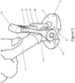
- Motion of the securing member 20 continues until the securing position is reached in which the handle 14 is substantially vertically orientated and perpendicular to its initial position. This position is shown in Figure 5 .
- Figure 5 shows the foot 3 in the secure state of attachment to the leg 4.
- the securing member 20 can be seen to be inserted fully into the recess 30 and handle 14 can be seen extending upwardly clearly to provide a clear indication that the foot 4 and leg 2 are attached securely.
- the securing member 20 When in the securing position, the securing member 20 is held in position against accidental movement, by the resilience of the handle 14 and frictional forces which act to oppose movement of the securing member 20 along the recess to the release position. This is aided by ridges in the back wall 32 of the recess 30. In order for the securing member 20 to exit the recess, then as the securing member 20 moves, the end of the securing member 20 engages the rear surface 32 of the recess 20. The frictional force thereby generated due to the movement is enhanced by the pivoting engagement between the securing member 20 and the upper edge 34 of the front wall 28 which acts to force the end of the securing member 20 against the rear surface 32, so increasing the frictional force resisting movement.
- the user grips the handle 14 and moves this in the opposite direction to the direction A used to secure the foot 2 to the leg 4 shown in Figure 4 .
- the lever action of the handle 14 acting about the aforementioned fulcrum enables the securing member 20 to be removed from the recess 30, with relative ease, but only when required.
- the recess 30 is formed through provision of an upwardly extending front wall 28 and upwardly extending back wall 32.
- the front wall 28 has a height which is shorter than the back wall 32 and has a curved outer face. Both the inner faces of the front wall and back wall of the recess 30 are substantially flat, joining together at a convexly curved base.
- the back wall 32 may have grooves or ridges to increase the level of friction.
- Figure 6 shows an example of the invention in use, whereby feet 2 are secured to the legs 4 of a tripod 40.
- the gripping portion 16 consists of a horizontally attached gripping element 18 which is cylindrical in shape, however in alternative examplesthis gripping portion is suitably sized and shaped to enable a user to grip. For instance, in alternative example there are finger indentations or an arched cylinder.
- the handle 14 can be attached to the foot 2 at just one pivot point.
- the gripping element 18 can include grooves, indentations or any suitable gripping material or texture.
- the gripping element 18 can be any suitable design to enhance the gripping ability.
- the description also envisages that the foot 2 described may be used in combination with different foot designs to accommodate different surface types.
- foot 2 described can be used on any leg 4 which requires exchangeable and removable feet including, but not limited to, tripods, monopods, easels, parasols and garden furniture.
- the leg 4 of the tripod is not necessarily sitting upon an axle mount 12 on the foot 2 but the foot includes a leg receiving recess enabling a leg to rest in the receiving recess allowing the foot to provide a housing for a leg as the foot is secured thereto.
- a foot can therefore be usable for different legs.
- the entire securing assembly 6 and recess 30 is separable from both the foot 2 and the leg 4 of a tripod 40.
- the recess 30 may be an attached part of the foot but is separable from the leg 4 of the tripod 40.
- a foot 200 is attached by a securing assembly to a leg 42.
- the foot 200 shown in Figure 7 is shown in a secured state.
- the foot 200 has a flat base 8 to provide good contact with the surface on which the tripod stands and an outwardly curved upper part 10.
- Mounted on the upper surface of the foot 200 is an axle mount 12 to which a handle 140 is pivotally attached.
- the handle 140 is made of a suitable solid rubber material, as in the above described examples.
- a securing member 201 is attached to the handle 140.
- the central portion of the handle 140 which formed the gripping portion in the first embodiment is attached to the securing member 201.
- the gripping portion of the handle 140 is gripped within a central recess 220 within the securing member 201 which is shaped appropriately to grip and retain the handle 140.
- the gripping portion is substantially a parallelepiped to enable gripping by the central recess whose shape matches the shape of the gripping portion.
- the central positioning is advantageous as it provides symmetry and thus even application of securing forces, with an even wear of the handle and other component.
- the securing member 201 is preferably made of a suitable hard plastics material.
- the securing member 201 has a side recess 202 on a side of the securing member which is opposite to that of central recess 220 which engages with the handle, as can be seen for example in Figure 9A .
- the securing member 201 has two ends, 201A and 201B.
- the end 201A which is closer to the side recess 202 of the securing member 201 engages with a substantially vertically orientated recess 30 of the leg 41. Accordingly, embodiments of Figures 7 to 12 differ from the examples of Figures 2 to 6 particularly in that the securing member 201 has two free ends (instead of one as securing member 20) and two recesses (securing member 20 has none).
- the upper end 201B of the securing member 201 may be used as a lever to enable the user to release the securing assembly and the recesses of the securing member 201 itself enable engagement with the handle and leg 41. It will be appreciated that possible modifications mentioned above in respect of the examples of Figures 2 to 6 also apply to the examples of Figures 7 to 12 .
- the recess 30 of the leg portion 40 has a back wall 32 having a greater height than the front wall 28.
- end 201A of the securing member 201 is inwardly arched and the arch matches the curvature of the recess 30.
- the recess 30 substantially matches the locus of movement of the end 201A of the securing member 201 during operation.
- the upper end of the front wall 28A fits within the side recess 202 when the securing assembly is in the non-secured state.
- the securing member 201 rests on the upper end of the front wall 28A, being held between the upper end of the front wall 28A and the handle140.
- the engagement of the upper end of the front wall 28A with the side recess 202 enables the securing member to be held in place between the upper end of the front wall 28A (edge) and the handle 140.
- the end of the leg 41 is profiled to conform to the axle mount 12 and has an arched conformation to fit about in contiguous relationship with said axle mount 12.
- the upper end 201B of the securing member is moved in the downwards direction as indicated by the arrow B, which rotates the securing member 201 and in particular the pivoted end 201A of the securing member 201.
- This rotation of the securing member 201 rotates the handle 140 in the same direction, and also initially stretches the handle 140 due to the different locations of the pivot point 201A for the securing member and 12 for the handle.
- a user may rotate the upper end 201B in the direction of the arrow to enable pivoting of the end 201A within the recess 30 and movement of the handle 140.
- the shape of the securing member 201 enables the user to carry out the release movement by pressing with the thumb onto the upper end 201B of the securing member.
- the contact between the pivoted end 201A of the securing member 201 and the recess 30 acts as a first fulcrum for the motion of the handle 140. Further, in continuing to carry out this action, the contact between the side recess 202 of the securing member 201 and the edge 28A of the front wall 28 acts as a second fulcrum for the motion of the securing member 201.
- the mechanical advantage gained thereby assists the user in moving the securing member 20 from the rest position to the securing position.
- the handle 140 In the securing position, the handle 140 is substantially vertically orientated. Motion of the securing member 201 continues until the non-securing position is reached, and the handle is at an angle from the vertical. In use, when the handle 140 is in the non-secured position, the foot 200 is not firmly secured to the leg 41, which is merely resting upon the axle mount 12 and the leg 41 can therefore be easily moved away from the foot 2 and vice versa.
- Figure 10 is a back view of an embodiment of the foot of Figure 7 and Figure 11 is a top perspective view of an embodiment of the foot of Figure 7 .
- Figure 12 is a view from the bottom of an embodiment of the foot of Figure 7 which shows the flat base 8 having a profiled portion (preferably made of rubber) to provide good grip to the surface onto which the leg is positioned.
Landscapes
- Engineering & Computer Science (AREA)
- General Engineering & Computer Science (AREA)
- Mechanical Engineering (AREA)
- Physics & Mathematics (AREA)
- General Physics & Mathematics (AREA)
- Purses, Travelling Bags, Baskets, Or Suitcases (AREA)
- Legs For Furniture In General (AREA)
- Ladders (AREA)
Claims (13)
- Schenkel (41) mit einem Fuß, wobei der Fuß einen Basisabschnitt und einen dehnbaren Griff (140) aus einem elastischen Material aufweist, wobei der Griff (140) an einem ersten Ende schwenkbar an dem Basisabschnitt befestigt ist und an einem zweiten Ende einen Greifabschnitt (220) aufweist, wobei der Griff (140) ferner umfassend ein zentral eingesetztes, starres Sicherungselement (201), das an dem Greifabschnitt (220) befestigt ist, wobei der Griff (140) zwischen einer ersten Position, in der der Fuß vom Schenkel abnehmbar ist, und einer zweiten Position, in der ein Ende des Sicherungselements (201) innerhalb einer Befestigungsaussparung im Schenkelabschnitt befestigt ist, beweglich ist, wodurch der Fuß am Schenkel befestigt ist, wobei das Sicherungselement (201) eine Schenkelaufnahmeaussparung zur Aufnahme einer Kante des Schenkels aufweist, wobei das Sicherungselement (201) an der Kante schwenkbar ist, wenn sich der Griff (140) in der ersten Position befindet, dadurch gekennzeichnet, dass sich das Sicherungselement (201) vom Greifabschnitt (220) des Griffs weg erstreckt und innerhalb einer Öffnung des Griffs, der ein Sicherungselement aufnimmt, in einer Richtung distal zum Ende des Sicherungselements (201) befestigt ist, das im Gebrauch an der Befestigungsaussparung befestigt ist.
- Schenkel (41) nach Anspruch 1, wobei im Gebrauch die Befestigungsaussparung im Wesentlichen vertikal ausgerichtet ist.
- Schenkel (41) nach einem der vorhergehenden Ansprüche, wobei das Sicherungselement (201) innerhalb der Befestigungsaussparung durch eine überzentrische Rastwirkung bei der Betätigung des Mechanismus zwischen dem Sicherungselement und der Befestigungsaussparung gehalten wird.
- Schenkel (41) nach einem der vorhergehenden Ansprüche, wobei das Sicherungselement (201) eine Griffaufnahmeaussparung zum Greifen des Greifabschnitts des Griffs aufweist.
- Schenkel (41) nach einem der vorhergehenden Ansprüche, wobei das Sicherungselement (201) schwenkbar innerhalb der Aufnahmeöffnung des Griffs befestigt ist.
- Schenkel (41) nach einem der vorhergehenden Ansprüche, wobei der Greifabschnitt (220) geriffelt ist.
- Schenkel (41) nach einem der vorhergehenden Ansprüche, wobei die Befestigungsaussparung eine Rückwand und eine Vorderwand aufweist und wobei die Vorderwand eine Höhe aufweist, die kürzer als die Rückwand ist.
- Schenkel (41) nach einem der vorhergehenden Ansprüche, wobei das Sicherungselement aus einem harten Kunststoffmaterial besteht.
- Schenkel (41) nach einem der vorhergehenden Ansprüche, wobei der Griff (140) aus einem Vollgummimaterial besteht.
- Schenkel (41) nach einem der vorhergehenden Ansprüche, wobei das Ende des Sicherungselements, das bei Verwendung an der Befestigungsaussparung befestigt ist, konkav gebogen ist.
- Schenkel (41) nach Anspruch 10, wobei die Vorderwand der Befestigungsaussparung eine Außenfläche aufweist, die konvex gekrümmt ist, was einer Kurve des Endes des Sicherungselements entspricht.
- Schenkel (41) nach einem der vorhergehenden Ansprüche, wobei der Griff (140) durch zwei gegenüberliegende Schwenkhalterungen schwenkbar mit dem Fuß verbunden ist.
- Stativhalterung mit einem Schenkel (41) gemäß einem der vorhergehenden Ansprüche.
Applications Claiming Priority (4)
| Application Number | Priority Date | Filing Date | Title |
|---|---|---|---|
| GB1605836.4A GB2549119A (en) | 2016-04-06 | 2016-04-06 | A tripod foot |
| GBGB1608265.3A GB201608265D0 (en) | 2016-05-11 | 2016-05-11 | A Tripod foot |
| GB1701937.3A GB2549171A (en) | 2016-04-06 | 2017-02-06 | A tripod foot |
| PCT/GB2017/050768 WO2017174958A1 (en) | 2016-04-06 | 2017-03-20 | A tripod foot |
Publications (2)
| Publication Number | Publication Date |
|---|---|
| EP3398015A1 EP3398015A1 (de) | 2018-11-07 |
| EP3398015B1 true EP3398015B1 (de) | 2019-09-11 |
Family
ID=58462462
Family Applications (1)
| Application Number | Title | Priority Date | Filing Date |
|---|---|---|---|
| EP17713410.3A Active EP3398015B1 (de) | 2016-04-06 | 2017-03-20 | Fuss für stativ |
Country Status (5)
| Country | Link |
|---|---|
| US (1) | US10794531B2 (de) |
| EP (1) | EP3398015B1 (de) |
| CN (1) | CN108780269B (de) |
| GB (1) | GB2549171A (de) |
| WO (1) | WO2017174958A1 (de) |
Families Citing this family (4)
| Publication number | Priority date | Publication date | Assignee | Title |
|---|---|---|---|---|
| GB2575783B (en) | 2018-07-18 | 2021-03-10 | Vitec Group Plc | Tripod Leg Spreader |
| GB2582820B (en) | 2019-04-05 | 2023-06-28 | Videndum Plc | A head assembly for a tripod |
| JP7587274B2 (ja) * | 2021-11-08 | 2024-11-20 | 星野楽器株式会社 | スタンドの脚開き角度変更部材、及びスタンド |
| CN221424290U (zh) * | 2023-12-14 | 2024-07-26 | 深圳市乐其网络科技有限公司 | 可拆卸支脚、支腿及摄影支架 |
Family Cites Families (69)
| Publication number | Priority date | Publication date | Assignee | Title |
|---|---|---|---|---|
| US2736130A (en) * | 1956-02-28 | Foot for furniture leg | ||
| US1486508A (en) * | 1921-04-06 | 1924-03-11 | Laurence V Coleman | Tripod |
| US1563700A (en) * | 1924-09-10 | 1925-12-01 | William B Frankenstein | Adjustable ladder shoe |
| US1679461A (en) * | 1927-04-25 | 1928-08-07 | Worsching Richard | Antislipping device for stands and the like |
| US1814334A (en) * | 1928-09-19 | 1931-07-14 | Potigian Armen | Tripod foot |
| US2277939A (en) * | 1939-08-07 | 1942-03-31 | Thomas W Sukumlyn | Leg rest |
| US2853261A (en) * | 1954-05-25 | 1958-09-23 | Loeb Leo | Stabilizer for containers |
| US2868427A (en) * | 1957-04-12 | 1959-01-13 | George R Hess | Safety support for ladders |
| US3191706A (en) * | 1960-09-06 | 1965-06-29 | Douglas Aircraft Co Inc | Pneumatic support |
| US3603547A (en) * | 1968-11-27 | 1971-09-07 | Applied Technical Services Inc | Stabilizing and leveling device |
| DE2612409C3 (de) * | 1976-03-24 | 1979-09-20 | Sachtler Gmbh Filmtechnische Geraete, 8000 Muenchen | Bodenspinne für Dreibeinstative |
| US4379541A (en) * | 1979-07-23 | 1983-04-12 | Harkness Donald M | Holder for a container |
| US4474387A (en) * | 1982-03-08 | 1984-10-02 | Maranell Melvin C | Kickstand supporting device |
| US4852836A (en) * | 1987-10-22 | 1989-08-01 | Michio Kawazoe | Tripod |
| US4971347A (en) * | 1989-04-17 | 1990-11-20 | Cline Jack B | Motorcycle kick stand attachment |
| US4965914A (en) * | 1990-02-21 | 1990-10-30 | General Motors Corporation | Overcenter clamp |
| US5003328A (en) * | 1990-05-24 | 1991-03-26 | Gaynor Tyrone L | Photographic tripod apparatus |
| US5078231A (en) * | 1991-05-14 | 1992-01-07 | Davis Allen N | Ladder base plate apparatus |
| US5210903A (en) * | 1991-12-16 | 1993-05-18 | Horning Jerry L | Furniture caster stop and process of immobilizing a caster |
| DE4200771C2 (de) * | 1992-01-14 | 1993-11-11 | Martin Eder | Wiederöffenbarer Kabelbinder |
| US5351981A (en) * | 1992-07-31 | 1994-10-04 | Janko U.S.A. | Bicycle kickstand accessory |
| AU6004594A (en) * | 1993-02-09 | 1994-08-29 | Jacob's Ladder Bases Limited | Ladder etc. support |
| WO1995011505A1 (en) * | 1993-10-21 | 1995-04-27 | Signfix Limited | Mounting device |
| DE29613592U1 (de) * | 1996-08-06 | 1996-09-19 | Gottlieb Nestle GmbH & Co KG, 72280 Dornstetten | Steh- und Einstelleinrichtung insbesondere für Vermessungsinstrumente |
| US6021984A (en) * | 1997-06-02 | 2000-02-08 | Mills; James Everett | Bracket for attachment of optical devices and other support apparatuses to support objects |
| US6389655B2 (en) * | 1999-06-09 | 2002-05-21 | Denis E. Libecco | Adjustable elastic tie-down cord |
| US6340166B1 (en) * | 1999-06-11 | 2002-01-22 | David A. Rethman | Kickstand support base for motorcycles |
| US6669221B2 (en) * | 2000-07-26 | 2003-12-30 | Sink-No-Bob, Ltd. Co. | Motorcycle kickstand anti-sink attachment |
| AUPQ910500A0 (en) * | 2000-07-31 | 2000-08-24 | R.E. Miller Pty. Ltd. | Support means |
| GB2366592B8 (en) * | 2000-09-06 | 2017-06-21 | Vitec Group Plc | Improvements in or relating to clamps for elongate members |
| US6355887B1 (en) * | 2001-02-09 | 2002-03-12 | Arlington Industries, Inc. | Cable support |
| US20040135042A1 (en) * | 2001-02-28 | 2004-07-15 | Klaus Krinner | Stand for mounting and vertically holding bar-shaped parts |
| US6572061B2 (en) * | 2001-06-25 | 2003-06-03 | Overbeck/Ahern Llc | Adjustable base structure |
| US7124985B2 (en) * | 2002-04-19 | 2006-10-24 | Crain Enterprises, Inc. | Geomatic pole support with telescoping legs and locks |
| US20050045681A1 (en) * | 2003-08-25 | 2005-03-03 | Hancock Dennis H. | All terrain vehicle portable radio mount |
| US6910246B2 (en) * | 2003-11-06 | 2005-06-28 | Innovation Engineering Group | Furniture leg glide |
| US7281689B1 (en) * | 2003-11-21 | 2007-10-16 | Michael R Johnston | Pipe support assembly |
| US20060086871A1 (en) * | 2004-10-27 | 2006-04-27 | Council Of Scientific And Industrial Research | Adjustable tripod mechanism to support devices or transducers for scientific measurement |
| US7533858B2 (en) * | 2005-04-05 | 2009-05-19 | Acp, Llc | Furniture glide |
| US7213869B1 (en) * | 2005-04-08 | 2007-05-08 | Mcclellan Robert N | Hold down |
| DE202005010632U1 (de) * | 2005-07-06 | 2005-10-27 | Krinner Innovation Gmbh | Haltevorrichtung für stabförmige Bauteile |
| US7401850B2 (en) * | 2006-03-14 | 2008-07-22 | Micheel Thomas G | Locking device for collapsible seat |
| US20070290104A1 (en) * | 2006-06-14 | 2007-12-20 | Tri-Ped Corporation | Apparatus for stabilizing a tripod |
| US7770853B2 (en) * | 2007-02-12 | 2010-08-10 | Shiffler Equipment Sales, Inc. | Two piece snap-fit cap or glide |
| US20080283697A1 (en) * | 2007-04-27 | 2008-11-20 | Richard Darrow | Apparatuses and systems for supporting and positioning cameras and other equipment |
| WO2008134698A1 (en) * | 2007-04-30 | 2008-11-06 | Ferno-Washington, Inc. | High directional having a configurable number of telescoping legs |
| WO2009006488A2 (en) * | 2007-07-02 | 2009-01-08 | Core Consulting, Llc | Crutch assembly |
| US8136771B2 (en) * | 2008-04-30 | 2012-03-20 | Cazalet Michael E | Modular clamping system |
| JP4344003B1 (ja) * | 2008-06-05 | 2009-10-14 | 関西工事測量株式会社 | 三脚支持装置及び三脚装置 |
| US7621550B1 (en) * | 2008-08-06 | 2009-11-24 | Andrew Wayne Boruff | Detachable kickstand support with mounting bracket |
| US8747418B2 (en) * | 2008-08-15 | 2014-06-10 | Monteris Medical Corporation | Trajectory guide |
| US20100050389A1 (en) * | 2008-08-27 | 2010-03-04 | Waxman Consumer Products Group Inc. | Furniture slide assemblies and method of use |
| CN100578068C (zh) * | 2008-09-18 | 2010-01-06 | 陆伟明 | 三段一体式伸缩三脚架 |
| DE202008014053U1 (de) * | 2008-10-22 | 2010-03-11 | Mann+Hummel Gmbh | Spannverschluss für Filtergehäuse |
| CN101609247A (zh) * | 2009-06-23 | 2009-12-23 | 刘昊 | 一种平板式三脚架 |
| CN201628065U (zh) * | 2009-10-10 | 2010-11-10 | 中山立信摄影器材有限公司 | 便携三脚架 |
| CA2726399A1 (en) * | 2009-12-23 | 2011-06-23 | Sherman Marquardt | Insulated foot pad for a tripod |
| US8813407B1 (en) * | 2011-02-03 | 2014-08-26 | Craig J. Sargent | Adjustable firearm rest |
| US20130119213A1 (en) * | 2011-09-13 | 2013-05-16 | Tom Watson | Ladder Retaining Apparatus |
| US9247997B2 (en) * | 2011-09-30 | 2016-02-02 | Ethicon Endo-Surgery, Inc. | Patient-referenced surgical support frame |
| US20130105662A1 (en) * | 2011-11-02 | 2013-05-02 | The Grablet, LLC | Easily Attachable/Detachable, Multi-Function Support For A Tablet Personal Computer |
| CN202631929U (zh) * | 2012-04-16 | 2012-12-26 | 威宝摄影器材有限公司 | 一种快速拉伸锁紧的反折叠相机三脚架 |
| US9400082B2 (en) * | 2013-03-10 | 2016-07-26 | Marc W. Webster | Camera mounting system |
| US9213222B2 (en) * | 2013-04-05 | 2015-12-15 | Really Right Stuff, Llc | Control arm for an imaging device |
| CN204284849U (zh) * | 2014-10-29 | 2015-04-22 | 于吉星 | 具轨道效果的摄影机脚架 |
| US9615662B1 (en) * | 2014-11-03 | 2017-04-11 | John L. Amber | Furniture slide assembly |
| US9810023B2 (en) * | 2016-01-11 | 2017-11-07 | Craig Stewart | Climbing system |
| US20170234480A1 (en) * | 2016-02-16 | 2017-08-17 | Poly-Tech Industrial Inc. | Tree and pole support |
| US9554639B1 (en) * | 2016-03-29 | 2017-01-31 | Bby Solutions, Inc. | Action camera foot mount |
-
2017
- 2017-02-06 GB GB1701937.3A patent/GB2549171A/en not_active Withdrawn
- 2017-03-20 WO PCT/GB2017/050768 patent/WO2017174958A1/en not_active Ceased
- 2017-03-20 US US16/079,923 patent/US10794531B2/en active Active
- 2017-03-20 CN CN201780013780.5A patent/CN108780269B/zh active Active
- 2017-03-20 EP EP17713410.3A patent/EP3398015B1/de active Active
Non-Patent Citations (1)
| Title |
|---|
| None * |
Also Published As
| Publication number | Publication date |
|---|---|
| GB2549171A (en) | 2017-10-11 |
| US10794531B2 (en) | 2020-10-06 |
| US20190049062A1 (en) | 2019-02-14 |
| WO2017174958A1 (en) | 2017-10-12 |
| CN108780269A (zh) | 2018-11-09 |
| EP3398015A1 (de) | 2018-11-07 |
| CN108780269B (zh) | 2021-03-02 |
| GB201701937D0 (en) | 2017-03-22 |
Similar Documents
| Publication | Publication Date | Title |
|---|---|---|
| US10794531B2 (en) | Tripod foot | |
| EP2467039B1 (de) | Gehstock | |
| US8919362B1 (en) | Walking cane with platform | |
| US20170136342A1 (en) | Power and stabilizing apparatus | |
| EP2999373B1 (de) | Ausrüstung für den einsatz beim sitzen und beim laufen, skifahren oder ähnliches | |
| US11197523B2 (en) | Auxiliary handle for a walking assistance device | |
| WO2015132565A1 (en) | Mobile device stand | |
| US8628143B2 (en) | Corner-braced, portable, foot prop | |
| MX2014002506A (es) | Dispositivo de agarre desprendible para un recipiente de coccion equipado con medios de retencion para dos brazos. | |
| EP2699323A1 (de) | Hilfssystem für ein gleitbrett oder einen schneeschuh | |
| US9834988B1 (en) | Ladder platform attachment | |
| FR3044235A1 (fr) | Poignee et sa dragonne amovible de baton de ski ou de marche | |
| FR2641469A1 (fr) | Appareil de gymnastique recreative | |
| US20160116104A1 (en) | Collapsible Three Legged Platform | |
| US10782595B2 (en) | Handle with arm support used for photography equipment | |
| EP3280286A1 (de) | Schuhwerk zum bewegen auf wänden aus perforierten verkleidungsplatten | |
| GB2549119A (en) | A tripod foot | |
| US20050035251A1 (en) | Clamp attachment for a cane | |
| FR2957264A1 (fr) | Systeme de fixation d'une chaussure sur un engin de glisse | |
| KR101008662B1 (ko) | 신발 벗김 보조기구 | |
| US20260076440A1 (en) | Walking-aid footwear | |
| JP7553734B1 (ja) | 靴ベラ | |
| US20200345165A1 (en) | Footwear Removal Device | |
| JP3105423U (ja) | アイロン掛け用基台 | |
| GB2453926A (en) | Boot jack |
Legal Events
| Date | Code | Title | Description |
|---|---|---|---|
| STAA | Information on the status of an ep patent application or granted ep patent |
Free format text: STATUS: UNKNOWN |
|
| STAA | Information on the status of an ep patent application or granted ep patent |
Free format text: STATUS: THE INTERNATIONAL PUBLICATION HAS BEEN MADE |
|
| PUAI | Public reference made under article 153(3) epc to a published international application that has entered the european phase |
Free format text: ORIGINAL CODE: 0009012 |
|
| STAA | Information on the status of an ep patent application or granted ep patent |
Free format text: STATUS: REQUEST FOR EXAMINATION WAS MADE |
|
| 17P | Request for examination filed |
Effective date: 20180725 |
|
| AK | Designated contracting states |
Kind code of ref document: A1 Designated state(s): AL AT BE BG CH CY CZ DE DK EE ES FI FR GB GR HR HU IE IS IT LI LT LU LV MC MK MT NL NO PL PT RO RS SE SI SK SM TR |
|
| AX | Request for extension of the european patent |
Extension state: BA ME |
|
| GRAP | Despatch of communication of intention to grant a patent |
Free format text: ORIGINAL CODE: EPIDOSNIGR1 |
|
| STAA | Information on the status of an ep patent application or granted ep patent |
Free format text: STATUS: GRANT OF PATENT IS INTENDED |
|
| DAV | Request for validation of the european patent (deleted) | ||
| DAX | Request for extension of the european patent (deleted) | ||
| INTG | Intention to grant announced |
Effective date: 20190523 |
|
| GRAJ | Information related to disapproval of communication of intention to grant by the applicant or resumption of examination proceedings by the epo deleted |
Free format text: ORIGINAL CODE: EPIDOSDIGR1 |
|
| STAA | Information on the status of an ep patent application or granted ep patent |
Free format text: STATUS: REQUEST FOR EXAMINATION WAS MADE |
|
| GRAP | Despatch of communication of intention to grant a patent |
Free format text: ORIGINAL CODE: EPIDOSNIGR1 |
|
| STAA | Information on the status of an ep patent application or granted ep patent |
Free format text: STATUS: GRANT OF PATENT IS INTENDED |
|
| GRAS | Grant fee paid |
Free format text: ORIGINAL CODE: EPIDOSNIGR3 |
|
| INTC | Intention to grant announced (deleted) | ||
| GRAA | (expected) grant |
Free format text: ORIGINAL CODE: 0009210 |
|
| STAA | Information on the status of an ep patent application or granted ep patent |
Free format text: STATUS: THE PATENT HAS BEEN GRANTED |
|
| INTG | Intention to grant announced |
Effective date: 20190718 |
|
| AK | Designated contracting states |
Kind code of ref document: B1 Designated state(s): AL AT BE BG CH CY CZ DE DK EE ES FI FR GB GR HR HU IE IS IT LI LT LU LV MC MK MT NL NO PL PT RO RS SE SI SK SM TR |
|
| REG | Reference to a national code |
Ref country code: GB Ref legal event code: FG4D |
|
| REG | Reference to a national code |
Ref country code: CH Ref legal event code: EP |
|
| REG | Reference to a national code |
Ref country code: AT Ref legal event code: REF Ref document number: 1179215 Country of ref document: AT Kind code of ref document: T Effective date: 20190915 |
|
| REG | Reference to a national code |
Ref country code: DE Ref legal event code: R096 Ref document number: 602017007006 Country of ref document: DE Ref country code: IE Ref legal event code: FG4D |
|
| REG | Reference to a national code |
Ref country code: NL Ref legal event code: MP Effective date: 20190911 |
|
| REG | Reference to a national code |
Ref country code: LT Ref legal event code: MG4D |
|
| PG25 | Lapsed in a contracting state [announced via postgrant information from national office to epo] |
Ref country code: FI Free format text: LAPSE BECAUSE OF FAILURE TO SUBMIT A TRANSLATION OF THE DESCRIPTION OR TO PAY THE FEE WITHIN THE PRESCRIBED TIME-LIMIT Effective date: 20190911 Ref country code: SE Free format text: LAPSE BECAUSE OF FAILURE TO SUBMIT A TRANSLATION OF THE DESCRIPTION OR TO PAY THE FEE WITHIN THE PRESCRIBED TIME-LIMIT Effective date: 20190911 Ref country code: HR Free format text: LAPSE BECAUSE OF FAILURE TO SUBMIT A TRANSLATION OF THE DESCRIPTION OR TO PAY THE FEE WITHIN THE PRESCRIBED TIME-LIMIT Effective date: 20190911 Ref country code: NO Free format text: LAPSE BECAUSE OF FAILURE TO SUBMIT A TRANSLATION OF THE DESCRIPTION OR TO PAY THE FEE WITHIN THE PRESCRIBED TIME-LIMIT Effective date: 20191211 Ref country code: LT Free format text: LAPSE BECAUSE OF FAILURE TO SUBMIT A TRANSLATION OF THE DESCRIPTION OR TO PAY THE FEE WITHIN THE PRESCRIBED TIME-LIMIT Effective date: 20190911 Ref country code: BG Free format text: LAPSE BECAUSE OF FAILURE TO SUBMIT A TRANSLATION OF THE DESCRIPTION OR TO PAY THE FEE WITHIN THE PRESCRIBED TIME-LIMIT Effective date: 20191211 |
|
| PG25 | Lapsed in a contracting state [announced via postgrant information from national office to epo] |
Ref country code: GR Free format text: LAPSE BECAUSE OF FAILURE TO SUBMIT A TRANSLATION OF THE DESCRIPTION OR TO PAY THE FEE WITHIN THE PRESCRIBED TIME-LIMIT Effective date: 20191212 Ref country code: LV Free format text: LAPSE BECAUSE OF FAILURE TO SUBMIT A TRANSLATION OF THE DESCRIPTION OR TO PAY THE FEE WITHIN THE PRESCRIBED TIME-LIMIT Effective date: 20190911 Ref country code: AL Free format text: LAPSE BECAUSE OF FAILURE TO SUBMIT A TRANSLATION OF THE DESCRIPTION OR TO PAY THE FEE WITHIN THE PRESCRIBED TIME-LIMIT Effective date: 20190911 Ref country code: ES Free format text: LAPSE BECAUSE OF FAILURE TO SUBMIT A TRANSLATION OF THE DESCRIPTION OR TO PAY THE FEE WITHIN THE PRESCRIBED TIME-LIMIT Effective date: 20190911 Ref country code: RS Free format text: LAPSE BECAUSE OF FAILURE TO SUBMIT A TRANSLATION OF THE DESCRIPTION OR TO PAY THE FEE WITHIN THE PRESCRIBED TIME-LIMIT Effective date: 20190911 |
|
| REG | Reference to a national code |
Ref country code: AT Ref legal event code: MK05 Ref document number: 1179215 Country of ref document: AT Kind code of ref document: T Effective date: 20190911 |
|
| PG25 | Lapsed in a contracting state [announced via postgrant information from national office to epo] |
Ref country code: EE Free format text: LAPSE BECAUSE OF FAILURE TO SUBMIT A TRANSLATION OF THE DESCRIPTION OR TO PAY THE FEE WITHIN THE PRESCRIBED TIME-LIMIT Effective date: 20190911 Ref country code: RO Free format text: LAPSE BECAUSE OF FAILURE TO SUBMIT A TRANSLATION OF THE DESCRIPTION OR TO PAY THE FEE WITHIN THE PRESCRIBED TIME-LIMIT Effective date: 20190911 Ref country code: NL Free format text: LAPSE BECAUSE OF FAILURE TO SUBMIT A TRANSLATION OF THE DESCRIPTION OR TO PAY THE FEE WITHIN THE PRESCRIBED TIME-LIMIT Effective date: 20190911 Ref country code: PL Free format text: LAPSE BECAUSE OF FAILURE TO SUBMIT A TRANSLATION OF THE DESCRIPTION OR TO PAY THE FEE WITHIN THE PRESCRIBED TIME-LIMIT Effective date: 20190911 Ref country code: PT Free format text: LAPSE BECAUSE OF FAILURE TO SUBMIT A TRANSLATION OF THE DESCRIPTION OR TO PAY THE FEE WITHIN THE PRESCRIBED TIME-LIMIT Effective date: 20200113 Ref country code: AT Free format text: LAPSE BECAUSE OF FAILURE TO SUBMIT A TRANSLATION OF THE DESCRIPTION OR TO PAY THE FEE WITHIN THE PRESCRIBED TIME-LIMIT Effective date: 20190911 |
|
| PG25 | Lapsed in a contracting state [announced via postgrant information from national office to epo] |
Ref country code: SK Free format text: LAPSE BECAUSE OF FAILURE TO SUBMIT A TRANSLATION OF THE DESCRIPTION OR TO PAY THE FEE WITHIN THE PRESCRIBED TIME-LIMIT Effective date: 20190911 Ref country code: CZ Free format text: LAPSE BECAUSE OF FAILURE TO SUBMIT A TRANSLATION OF THE DESCRIPTION OR TO PAY THE FEE WITHIN THE PRESCRIBED TIME-LIMIT Effective date: 20190911 Ref country code: SM Free format text: LAPSE BECAUSE OF FAILURE TO SUBMIT A TRANSLATION OF THE DESCRIPTION OR TO PAY THE FEE WITHIN THE PRESCRIBED TIME-LIMIT Effective date: 20190911 Ref country code: IS Free format text: LAPSE BECAUSE OF FAILURE TO SUBMIT A TRANSLATION OF THE DESCRIPTION OR TO PAY THE FEE WITHIN THE PRESCRIBED TIME-LIMIT Effective date: 20200224 |
|
| REG | Reference to a national code |
Ref country code: DE Ref legal event code: R097 Ref document number: 602017007006 Country of ref document: DE |
|
| PLBE | No opposition filed within time limit |
Free format text: ORIGINAL CODE: 0009261 |
|
| STAA | Information on the status of an ep patent application or granted ep patent |
Free format text: STATUS: NO OPPOSITION FILED WITHIN TIME LIMIT |
|
| PG2D | Information on lapse in contracting state deleted |
Ref country code: IS |
|
| PG25 | Lapsed in a contracting state [announced via postgrant information from national office to epo] |
Ref country code: DK Free format text: LAPSE BECAUSE OF FAILURE TO SUBMIT A TRANSLATION OF THE DESCRIPTION OR TO PAY THE FEE WITHIN THE PRESCRIBED TIME-LIMIT Effective date: 20190911 Ref country code: IS Free format text: LAPSE BECAUSE OF FAILURE TO SUBMIT A TRANSLATION OF THE DESCRIPTION OR TO PAY THE FEE WITHIN THE PRESCRIBED TIME-LIMIT Effective date: 20200112 |
|
| 26N | No opposition filed |
Effective date: 20200615 |
|
| PG25 | Lapsed in a contracting state [announced via postgrant information from national office to epo] |
Ref country code: MC Free format text: LAPSE BECAUSE OF FAILURE TO SUBMIT A TRANSLATION OF THE DESCRIPTION OR TO PAY THE FEE WITHIN THE PRESCRIBED TIME-LIMIT Effective date: 20190911 |
|
| REG | Reference to a national code |
Ref country code: CH Ref legal event code: PL |
|
| REG | Reference to a national code |
Ref country code: BE Ref legal event code: MM Effective date: 20200331 |
|
| PG25 | Lapsed in a contracting state [announced via postgrant information from national office to epo] |
Ref country code: LU Free format text: LAPSE BECAUSE OF NON-PAYMENT OF DUE FEES Effective date: 20200320 |
|
| PG25 | Lapsed in a contracting state [announced via postgrant information from national office to epo] |
Ref country code: CH Free format text: LAPSE BECAUSE OF NON-PAYMENT OF DUE FEES Effective date: 20200331 Ref country code: FR Free format text: LAPSE BECAUSE OF NON-PAYMENT OF DUE FEES Effective date: 20200331 Ref country code: IE Free format text: LAPSE BECAUSE OF NON-PAYMENT OF DUE FEES Effective date: 20200320 Ref country code: LI Free format text: LAPSE BECAUSE OF NON-PAYMENT OF DUE FEES Effective date: 20200331 |
|
| PG25 | Lapsed in a contracting state [announced via postgrant information from national office to epo] |
Ref country code: BE Free format text: LAPSE BECAUSE OF NON-PAYMENT OF DUE FEES Effective date: 20200331 |
|
| PG25 | Lapsed in a contracting state [announced via postgrant information from national office to epo] |
Ref country code: TR Free format text: LAPSE BECAUSE OF FAILURE TO SUBMIT A TRANSLATION OF THE DESCRIPTION OR TO PAY THE FEE WITHIN THE PRESCRIBED TIME-LIMIT Effective date: 20190911 Ref country code: MT Free format text: LAPSE BECAUSE OF FAILURE TO SUBMIT A TRANSLATION OF THE DESCRIPTION OR TO PAY THE FEE WITHIN THE PRESCRIBED TIME-LIMIT Effective date: 20190911 Ref country code: CY Free format text: LAPSE BECAUSE OF FAILURE TO SUBMIT A TRANSLATION OF THE DESCRIPTION OR TO PAY THE FEE WITHIN THE PRESCRIBED TIME-LIMIT Effective date: 20190911 |
|
| PG25 | Lapsed in a contracting state [announced via postgrant information from national office to epo] |
Ref country code: MK Free format text: LAPSE BECAUSE OF FAILURE TO SUBMIT A TRANSLATION OF THE DESCRIPTION OR TO PAY THE FEE WITHIN THE PRESCRIBED TIME-LIMIT Effective date: 20190911 |
|
| REG | Reference to a national code |
Ref country code: DE Ref legal event code: R081 Ref document number: 602017007006 Country of ref document: DE Owner name: VIDENDUM PLC, GB Free format text: FORMER OWNER: THE VITEC GROUP PLC, RICHMOND, GB Ref country code: DE Ref legal event code: R082 Ref document number: 602017007006 Country of ref document: DE Representative=s name: HOHENDORF KIERDORF PATENTANWAELTE PARTGMBB, DE Ref country code: DE Ref legal event code: R082 Ref document number: 602017007006 Country of ref document: DE Representative=s name: LIPPERT STACHOW PATENTANWAELTE RECHTSANWAELTE , DE |
|
| P01 | Opt-out of the competence of the unified patent court (upc) registered |
Effective date: 20230527 |
|
| PG25 | Lapsed in a contracting state [announced via postgrant information from national office to epo] |
Ref country code: SI Free format text: LAPSE BECAUSE OF FAILURE TO SUBMIT A TRANSLATION OF THE DESCRIPTION OR TO PAY THE FEE WITHIN THE PRESCRIBED TIME-LIMIT Effective date: 20190911 |
|
| REG | Reference to a national code |
Ref country code: DE Ref legal event code: R082 Ref document number: 602017007006 Country of ref document: DE Representative=s name: LIPPERT STACHOW PATENTANWAELTE RECHTSANWAELTE , DE |
|
| PGFP | Annual fee paid to national office [announced via postgrant information from national office to epo] |
Ref country code: GB Payment date: 20260227 Year of fee payment: 10 |
|
| PGFP | Annual fee paid to national office [announced via postgrant information from national office to epo] |
Ref country code: DE Payment date: 20260302 Year of fee payment: 10 |
|
| PGFP | Annual fee paid to national office [announced via postgrant information from national office to epo] |
Ref country code: IT Payment date: 20260311 Year of fee payment: 10 |