EP3396853B1 - Antriebssystem, automobil und verfahren zur steuerung des antriebssystems - Google Patents
Antriebssystem, automobil und verfahren zur steuerung des antriebssystems Download PDFInfo
- Publication number
- EP3396853B1 EP3396853B1 EP18169592.5A EP18169592A EP3396853B1 EP 3396853 B1 EP3396853 B1 EP 3396853B1 EP 18169592 A EP18169592 A EP 18169592A EP 3396853 B1 EP3396853 B1 EP 3396853B1
- Authority
- EP
- European Patent Office
- Prior art keywords
- unit
- motor
- carrier wave
- interval
- intervals
- Prior art date
- Legal status (The legal status is an assumption and is not a legal conclusion. Google has not performed a legal analysis and makes no representation as to the accuracy of the status listed.)
- Active
Links
Images




Classifications
-
- H—ELECTRICITY
- H02—GENERATION; CONVERSION OR DISTRIBUTION OF ELECTRIC POWER
- H02P—CONTROL OR REGULATION OF ELECTRIC MOTORS, ELECTRIC GENERATORS OR DYNAMO-ELECTRIC CONVERTERS; CONTROLLING TRANSFORMERS, REACTORS OR CHOKE COILS
- H02P23/00—Arrangements or methods for the control of AC motors characterised by a control method other than vector control
- H02P23/0004—Control strategies in general, e.g. linear type, e.g. P, PI, PID, using robust control
-
- H—ELECTRICITY
- H02—GENERATION; CONVERSION OR DISTRIBUTION OF ELECTRIC POWER
- H02P—CONTROL OR REGULATION OF ELECTRIC MOTORS, ELECTRIC GENERATORS OR DYNAMO-ELECTRIC CONVERTERS; CONTROLLING TRANSFORMERS, REACTORS OR CHOKE COILS
- H02P27/00—Arrangements or methods for the control of AC motors characterised by the kind of supply voltage
- H02P27/04—Arrangements or methods for the control of AC motors characterised by the kind of supply voltage using variable-frequency supply voltage, e.g. inverter or converter supply voltage
- H02P27/06—Arrangements or methods for the control of AC motors characterised by the kind of supply voltage using variable-frequency supply voltage, e.g. inverter or converter supply voltage using DC to AC converters or inverters
- H02P27/08—Arrangements or methods for the control of AC motors characterised by the kind of supply voltage using variable-frequency supply voltage, e.g. inverter or converter supply voltage using DC to AC converters or inverters with pulse width modulation
-
- B—PERFORMING OPERATIONS; TRANSPORTING
- B60—VEHICLES IN GENERAL
- B60L—PROPULSION OF ELECTRICALLY-PROPELLED VEHICLES; SUPPLYING ELECTRIC POWER FOR AUXILIARY EQUIPMENT OF ELECTRICALLY-PROPELLED VEHICLES; ELECTRODYNAMIC BRAKE SYSTEMS FOR VEHICLES IN GENERAL; MAGNETIC SUSPENSION OR LEVITATION FOR VEHICLES; MONITORING OPERATING VARIABLES OF ELECTRICALLY-PROPELLED VEHICLES; ELECTRIC SAFETY DEVICES FOR ELECTRICALLY-PROPELLED VEHICLES
- B60L50/00—Electric propulsion with power supplied within the vehicle
- B60L50/50—Electric propulsion with power supplied within the vehicle using propulsion power supplied by batteries or fuel cells
- B60L50/51—Electric propulsion with power supplied within the vehicle using propulsion power supplied by batteries or fuel cells characterised by AC-motors
-
- H—ELECTRICITY
- H02—GENERATION; CONVERSION OR DISTRIBUTION OF ELECTRIC POWER
- H02M—APPARATUS FOR CONVERSION BETWEEN AC AND AC, BETWEEN AC AND DC, OR BETWEEN DC AND DC, AND FOR USE WITH MAINS OR SIMILAR POWER SUPPLY SYSTEMS; CONVERSION OF DC OR AC INPUT POWER INTO SURGE OUTPUT POWER; CONTROL OR REGULATION THEREOF
- H02M7/00—Conversion of AC power input into DC power output; Conversion of DC power input into AC power output
- H02M7/42—Conversion of DC power input into AC power output without possibility of reversal
- H02M7/44—Conversion of DC power input into AC power output without possibility of reversal by static converters
- H02M7/48—Conversion of DC power input into AC power output without possibility of reversal by static converters using discharge tubes with control electrode or semiconductor devices with control electrode
- H02M7/53—Conversion of DC power input into AC power output without possibility of reversal by static converters using discharge tubes with control electrode or semiconductor devices with control electrode using devices of a triode or transistor type requiring continuous application of a control signal
- H02M7/537—Conversion of DC power input into AC power output without possibility of reversal by static converters using discharge tubes with control electrode or semiconductor devices with control electrode using devices of a triode or transistor type requiring continuous application of a control signal using semiconductor devices only, e.g. single switched pulse inverters
- H02M7/539—Conversion of DC power input into AC power output without possibility of reversal by static converters using discharge tubes with control electrode or semiconductor devices with control electrode using devices of a triode or transistor type requiring continuous application of a control signal using semiconductor devices only, e.g. single switched pulse inverters with automatic control of output wave form or frequency
- H02M7/5395—Conversion of DC power input into AC power output without possibility of reversal by static converters using discharge tubes with control electrode or semiconductor devices with control electrode using devices of a triode or transistor type requiring continuous application of a control signal using semiconductor devices only, e.g. single switched pulse inverters with automatic control of output wave form or frequency by pulse-width modulation
-
- H—ELECTRICITY
- H02—GENERATION; CONVERSION OR DISTRIBUTION OF ELECTRIC POWER
- H02P—CONTROL OR REGULATION OF ELECTRIC MOTORS, ELECTRIC GENERATORS OR DYNAMO-ELECTRIC CONVERTERS; CONTROLLING TRANSFORMERS, REACTORS OR CHOKE COILS
- H02P25/00—Arrangements or methods for the control of AC motors characterised by the kind of AC motor or by structural details
- H02P25/02—Arrangements or methods for the control of AC motors characterised by the kind of AC motor or by structural details characterised by the kind of motor
-
- H—ELECTRICITY
- H02—GENERATION; CONVERSION OR DISTRIBUTION OF ELECTRIC POWER
- H02P—CONTROL OR REGULATION OF ELECTRIC MOTORS, ELECTRIC GENERATORS OR DYNAMO-ELECTRIC CONVERTERS; CONTROLLING TRANSFORMERS, REACTORS OR CHOKE COILS
- H02P27/00—Arrangements or methods for the control of AC motors characterised by the kind of supply voltage
- H02P27/04—Arrangements or methods for the control of AC motors characterised by the kind of supply voltage using variable-frequency supply voltage, e.g. inverter or converter supply voltage
- H02P27/06—Arrangements or methods for the control of AC motors characterised by the kind of supply voltage using variable-frequency supply voltage, e.g. inverter or converter supply voltage using DC to AC converters or inverters
- H02P27/08—Arrangements or methods for the control of AC motors characterised by the kind of supply voltage using variable-frequency supply voltage, e.g. inverter or converter supply voltage using DC to AC converters or inverters with pulse width modulation
- H02P27/085—Arrangements or methods for the control of AC motors characterised by the kind of supply voltage using variable-frequency supply voltage, e.g. inverter or converter supply voltage using DC to AC converters or inverters with pulse width modulation wherein the PWM mode is adapted on the running conditions of the motor, e.g. the switching frequency
-
- H—ELECTRICITY
- H02—GENERATION; CONVERSION OR DISTRIBUTION OF ELECTRIC POWER
- H02P—CONTROL OR REGULATION OF ELECTRIC MOTORS, ELECTRIC GENERATORS OR DYNAMO-ELECTRIC CONVERTERS; CONTROLLING TRANSFORMERS, REACTORS OR CHOKE COILS
- H02P6/00—Arrangements for controlling synchronous motors or other dynamo-electric motors using electronic commutation dependent on the rotor position; Electronic commutators therefor
- H02P6/14—Electronic commutators
-
- B—PERFORMING OPERATIONS; TRANSPORTING
- B60—VEHICLES IN GENERAL
- B60L—PROPULSION OF ELECTRICALLY-PROPELLED VEHICLES; SUPPLYING ELECTRIC POWER FOR AUXILIARY EQUIPMENT OF ELECTRICALLY-PROPELLED VEHICLES; ELECTRODYNAMIC BRAKE SYSTEMS FOR VEHICLES IN GENERAL; MAGNETIC SUSPENSION OR LEVITATION FOR VEHICLES; MONITORING OPERATING VARIABLES OF ELECTRICALLY-PROPELLED VEHICLES; ELECTRIC SAFETY DEVICES FOR ELECTRICALLY-PROPELLED VEHICLES
- B60L2220/00—Electrical machine types; Structures or applications thereof
- B60L2220/50—Structural details of electrical machines
- B60L2220/58—Structural details of electrical machines with more than three phases
-
- B—PERFORMING OPERATIONS; TRANSPORTING
- B60—VEHICLES IN GENERAL
- B60Y—INDEXING SCHEME RELATING TO ASPECTS CROSS-CUTTING VEHICLE TECHNOLOGY
- B60Y2200/00—Type of vehicle
- B60Y2200/90—Vehicles comprising electric prime movers
- B60Y2200/91—Electric vehicles
-
- H—ELECTRICITY
- H02—GENERATION; CONVERSION OR DISTRIBUTION OF ELECTRIC POWER
- H02M—APPARATUS FOR CONVERSION BETWEEN AC AND AC, BETWEEN AC AND DC, OR BETWEEN DC AND DC, AND FOR USE WITH MAINS OR SIMILAR POWER SUPPLY SYSTEMS; CONVERSION OF DC OR AC INPUT POWER INTO SURGE OUTPUT POWER; CONTROL OR REGULATION THEREOF
- H02M7/00—Conversion of AC power input into DC power output; Conversion of DC power input into AC power output
- H02M7/42—Conversion of DC power input into AC power output without possibility of reversal
- H02M7/44—Conversion of DC power input into AC power output without possibility of reversal by static converters
- H02M7/48—Conversion of DC power input into AC power output without possibility of reversal by static converters using discharge tubes with control electrode or semiconductor devices with control electrode
- H02M7/53—Conversion of DC power input into AC power output without possibility of reversal by static converters using discharge tubes with control electrode or semiconductor devices with control electrode using devices of a triode or transistor type requiring continuous application of a control signal
- H02M7/537—Conversion of DC power input into AC power output without possibility of reversal by static converters using discharge tubes with control electrode or semiconductor devices with control electrode using devices of a triode or transistor type requiring continuous application of a control signal using semiconductor devices only, e.g. single switched pulse inverters
- H02M7/5387—Conversion of DC power input into AC power output without possibility of reversal by static converters using discharge tubes with control electrode or semiconductor devices with control electrode using devices of a triode or transistor type requiring continuous application of a control signal using semiconductor devices only, e.g. single switched pulse inverters in a bridge configuration
- H02M7/53871—Conversion of DC power input into AC power output without possibility of reversal by static converters using discharge tubes with control electrode or semiconductor devices with control electrode using devices of a triode or transistor type requiring continuous application of a control signal using semiconductor devices only, e.g. single switched pulse inverters in a bridge configuration with automatic control of output voltage or current
- H02M7/53875—Conversion of DC power input into AC power output without possibility of reversal by static converters using discharge tubes with control electrode or semiconductor devices with control electrode using devices of a triode or transistor type requiring continuous application of a control signal using semiconductor devices only, e.g. single switched pulse inverters in a bridge configuration with automatic control of output voltage or current with analogue control of three-phase output
- H02M7/53876—Conversion of DC power input into AC power output without possibility of reversal by static converters using discharge tubes with control electrode or semiconductor devices with control electrode using devices of a triode or transistor type requiring continuous application of a control signal using semiconductor devices only, e.g. single switched pulse inverters in a bridge configuration with automatic control of output voltage or current with analogue control of three-phase output based on synthesising a desired voltage vector via the selection of appropriate fundamental voltage vectors, and corresponding dwelling times
-
- H—ELECTRICITY
- H02—GENERATION; CONVERSION OR DISTRIBUTION OF ELECTRIC POWER
- H02P—CONTROL OR REGULATION OF ELECTRIC MOTORS, ELECTRIC GENERATORS OR DYNAMO-ELECTRIC CONVERTERS; CONTROLLING TRANSFORMERS, REACTORS OR CHOKE COILS
- H02P21/00—Arrangements or methods for the control of electric machines by vector control, e.g. by control of field orientation
-
- Y—GENERAL TAGGING OF NEW TECHNOLOGICAL DEVELOPMENTS; GENERAL TAGGING OF CROSS-SECTIONAL TECHNOLOGIES SPANNING OVER SEVERAL SECTIONS OF THE IPC; TECHNICAL SUBJECTS COVERED BY FORMER USPC CROSS-REFERENCE ART COLLECTIONS [XRACs] AND DIGESTS
- Y02—TECHNOLOGIES OR APPLICATIONS FOR MITIGATION OR ADAPTATION AGAINST CLIMATE CHANGE
- Y02T—CLIMATE CHANGE MITIGATION TECHNOLOGIES RELATED TO TRANSPORTATION
- Y02T10/00—Road transport of goods or passengers
- Y02T10/60—Other road transportation technologies with climate change mitigation effect
- Y02T10/70—Energy storage systems for electromobility, e.g. batteries
Definitions
- the invention relates to a drive system, an automobile, and a method of controlling the drive system, and more particularly to a drive system including a motor and an inverter, a method of controlling the drive system, and an automobile on which the drive system is installed.
- a drive system including a three-phase motor, and an inverter that converts DC voltage from a DC power source, into AC voltage, by switching ON/OFF of switching devices, and outputs the AC voltage to the motor, has been proposed (see Japanese Patent Application Publication No. 2016-5370 ( JP 2016-5370 A ), for example).
- the drive system is configured to generate a PWM (pulse width modulation) signal by comparing a modulation wave (fundamental wave) with a carrier wave, and output the signal to the inverter.
- PWM pulse width modulation
- the drive system determines a continuation period as a product of a 1/6 period of the modulation wave and a random number, calculates a plurality of carrier-wave frequencies by multiplying the frequency of the modulation wave by different coefficients that are multiples of 3 and odd numbers, and switches the carrier-wave frequencies according to the continuation period. In this manner, harmonics in given frequency bands are prevented from sticking out or becoming too large in amplitude, and electromagnetic noise is reduced.
- JP H09-47026 A discloses a PWM control inverter for an air conditioner. This document discloses varying the time intervals for switching the carrier frequency.
- EP 2 437 392 A1 discloses a control device for performing PWM control of an inverter.
- the number of the unit components in each unit interval (a 1/6 period of the modulation wave) is switched according to the continuation period (one unit interval, or two unit intervals, or three unit intervals, for example). Therefore, the number of unit components in each unit interval may not be set to a desired value. Namely, at least in the unit interval immediately after switching, the number of unit components in the unit interval immediately before switching cannot be selected.
- a drive system, automobile, and a method of controlling the drive system according to this invention reduce electromagnetic noise while making the number of unit components in each unit interval equal to a desired value.
- a first aspect of the invention is concerned with a drive system.
- the drive system includes a multi-phase motor, an inverter including a plurality of switching devices and configured to drive the motor through switching of the switching devices, and an electronic control unit configured to perform pulse width modulation control.
- the pulse width modulation control is a control that generates pulse width modulation signals of the plurality of switching devices by comparing a modulation wave of a voltage command of each phase based on a torque command of the motor, with a carrier wave, and performs switching of the plurality of switching devices.
- the electronic control unit is configured to generate the carrier wave so as to satisfy conditions (i) and (ii) as follows, where a unit component is a segment of the carrier wave between two consecutive extreme values, and a unit interval is an interval of a given electric angular width obtained by dividing one period of the modulation wave of the voltage command by twice the number of phases of the motor, while the carrier wave extends over a plurality of unit intervals.
- the above conditions are (i) in each of the unit intervals, a required time in the unit interval is equal to a total time of a plurality of unit components, and (ii) in at least one of the unit intervals, durations of at least two unit components of the plurality of unit components are different from each other.
- the electronic control unit generates the carrier wave, such that the required time in the unit interval is equal to the total time of the plurality of unit components, in each unit interval, and the durations of at least two unit components, out of the plurality of unit components, are different from each other, in at least one unit interval.
- the electronic control unit may be configured to generate the carrier wave such that the duration of the unit component changes irregularly. With this configuration, electromagnetic noise can be further reduced.
- the electronic control unit may be configured to generate the carrier wave such that the number of the unit components is constant in two consecutive unit intervals of unit intervals.
- the number of unit components in each unit interval can be made constant and equal to a desired value when the rotational speed of the motor and the synchronous number are constant.
- the "synchronous number" is the number of periods of the carrier wave in one period (360 degrees in electric angle) of the modulation wave of the voltage command of each phase.
- the electronic control unit may be configured to generate the carrier wave, such that, in two consecutive unit intervals as at least a part of the plurality of unit intervals, durations of the unit components immediately before and after a boundary of the two consecutive unit intervals may be equal to each other.
- the electronic control unit may be configured to generate the carrier wave, such that, in at least a part of the unit intervals in each of which the number of the unit components is equal to a first predetermined number, the durations of a second predetermined number of consecutive ones of the unit components in the same unit interval are equal to each other, where the first predetermined number is 3 or greater, and the second predetermined number is equal to or greater than 2 and less than the first predetermined number.
- the electronic control unit is configured to generate the carrier wave, such that each zero-crossing point in time at which the modulation wave of the voltage command of any of the phases crosses an axis of zero coincides with an end point in time of each of the unit intervals.
- the number of the phases of the motor is 3, and the required time in the unit interval is a period of time required for the motor to rotate 60 degrees in electric angle.
- a second aspect of the invention is concerned with a drive system.
- the drive system includes a multi-phase motor, an inverter including a plurality of switching devices and configured to drive the motor through switching of the switching devices, and an electronic control unit configured to perform pulse width modulation control.
- the pulse width modulation control is a control that generates pulse width modulation signals of the plurality of switching devices by comparing a modulation wave of a voltage command of each phase based on a torque command of the motor, with a carrier wave, and performs switching of the plurality of switching devices.
- the electronic control unit is configured to generate the carrier wave so as to satisfy conditions (i) and (ii) as follows, where a unit component is a segment of the carrier wave between two consecutive extreme values, and a unit interval is an interval of a given electric angular width obtained by dividing one period of the modulation wave of the voltage command by twice the number of phases of the motor, while the carrier wave extends over a plurality of unit intervals.
- the above conditions are (i) in each of the unit intervals, a required time in the unit interval is equal to a total time of a plurality of unit components, and (ii) in at least one of the unit intervals, frequencies of at least two unit components of the plurality of unit components are different from each other.
- the electronic control unit generates the carrier wave, such that the required time in the unit interval is equal to the total time of the plurality of unit components, in each unit interval, and the frequencies of at least two unit components, out of the plurality of unit components, are different from each other, in at least one unit interval.
- a third aspect of the invention is concerned with a drive system.
- the drive system includes a multi-phase motor, an inverter including a plurality of switching devices and configured to drive the motor through switching of the switching devices, and an electronic control unit configured to perform pulse width modulation control.
- the pulse width modulation control is to generate pulse width modulation signals of the plurality of switching devices by comparing a modulation wave of a voltage command of each phase based on a torque command of the motor, with a carrier wave, and perform switching of the plurality of switching devices.
- the electronic control unit is configured to generate the carrier wave so as to satisfy conditions (i) and (ii) as follows, where a unit component is a segment of the carrier wave between two consecutive extreme values, and a unit interval is an interval of a given electric angular width obtained by dividing one period of the modulation wave of the voltage command by twice the number of phases of the motor, while the carrier wave extends over a plurality of the unit intervals.
- the above conditions are (i) in each of the unit intervals, a required time in the unit interval is equal to a total time of a plurality of unit components, and (ii) in at least one of the unit intervals, absolute values of slopes of at least two unit components of the plurality of unit components are different from each other.
- the electronic control unit generates the carrier wave, such that the required time in the unit interval is equal to the total time of the plurality of unit components, in each unit interval, and the absolute values of the slopes of at least two unit components, out of the plurality of unit components, are different from each other, in at least one unit interval.
- a fourth aspect of the invention is concerned with a drive system.
- the drive system includes a multi-phase motor, an inverter including a plurality of switching devices and configured to drive the motor through switching of the switching devices, and an electronic control unit configured to perform pulse width modulation control.
- the pulse width modulation control is a control that generates pulse width modulation signals of the plurality of switching devices by comparing a modulation wave of a voltage command of each phase based on a torque command of the motor, with a carrier wave, and performs switching of the plurality of switching devices.
- the electronic control unit is configured to generate the carrier wave so as to satisfy conditions (i) and (ii) as follows, where a unit component is a segment of the carrier wave between two consecutive extreme values, and a unit interval is an interval of a given electric angular width obtained by dividing one period of the modulation wave of the voltage command by twice the number of phases of the motor, while the carrier wave extends over a plurality of unit intervals.
- the above conditions are (i) in each of the unit intervals, a required time in the unit interval is equal to a total time of a plurality of unit components, and (ii) in at least one of the unit intervals, electric angular widths of at least two unit components of the plurality of unit components are different from each other.
- the electronic control unit generates the carrier wave, such that the required time in the unit interval is equal to the total time of the plurality of unit components, in each unit interval, and the electric angular widths of at least two unit components, out of the plurality of unit components, are different from each other, in at least one unit interval.
- a fifth embodiment of the invention is concerned with an automobile on which the above-described drive system is installed, and which is configured to travel using power from the motor.
- the drive system of any aspect of the invention as described above is installed on the automobile; therefore, the automobile yields effects similar to the effects provided by the drive system as described above, for example, the effect to reduce electromagnetic noise while making the number of unit components in each unit interval equal to a desired value.
- the driver or passenger(s), and pedestrians, etc. around the automobile are less likely or unlikely to feel electromagnetic noise.
- a sixth embodiment of the invention is concerned with a method of controlling a drive system.
- the drive system includes a multi-phase motor, an inverter including a plurality of switching devices and configured to drive the motor through switching of the switching devices, and an electronic control unit configured to perform pulse width modulation control.
- the pulse width modulation control is a control that generates pulse width modulation signals of the plurality of switching devices by comparing a modulation wave of a voltage command of each phase based on a torque command of the motor, with a carrier wave, and performs switching of the plurality of switching devices.
- the method includes generating, by the electronic control unit, the carrier wave so as to satisfy conditions (i) and (ii) as follows, where a unit component is a segment of the carrier wave between two consecutive extreme values, and a unit interval is an interval of a given electric angular width obtained by dividing one period of the modulation wave of the voltage command by twice the number of phases of the motor, while the carrier wave extends over a plurality of unit intervals.
- a required time in the unit interval is equal to a total time of a plurality of unit components, and (ii) in at least one of the unit intervals, durations of at least two unit components of the plurality of unit components are different from each other, wherein the carrier wave is generated by the electronic control unit such that each zero-crossing point in time at which the modulation wave of the voltage command of any of the phases crosses an axis of zero coincides with an end point in time of each of the unit intervals, and wherein the number of the phases of the motor is 3, and the required time in the unit interval is a period of time required for the motor to rotate 60 degrees in electric angle.
- FIG. 1 schematically shows the configuration of an electric vehicle 20 on which a drive system as one embodiment of the invention is installed.
- the electric vehicle 20 of this embodiment includes a motor 32, inverter 34, battery 36 as a power storage device, boosting converter 40, and an electronic control unit 50.
- the motor 32 is in the form of a three-phase synchronous generator-motor, and includes a rotor in which permanent magnets are embedded, and a stator on which three-phase coils are wound.
- the rotor of the motor 32 is connected to a drive shaft 26 that is connected to drive wheels 22a, 22b via a differential gear unit 24.
- the inverter 34 is used for driving the motor 32.
- the inverter 34 is connected to the boosting converter 40 via a high-voltage-side power line 42, and has six transistors T11 - T16, and six diodes D11 - D16 connected in parallel with the six transistors T11 - T16, respectively.
- the transistors T11 - T16 are arranged in pairs such that the transistors of each pair are disposed on the source side and the sink side, between a positive line and a negative line of the high-voltage-side power line 42, respectively.
- three-phase coils (phase-U, phase-V, and phase-W coils) of the motor 32 are respectively connected to connection points between the corresponding pairs of transistors T11 - T16.
- the electronic control unit 50 controls the ratio of the ON times of each pair of the transistors T11 - T16, so that the three-phase coils form rotating magnetic fields, and the motor 32 is driven to be rotated.
- a smoothing capacitor 46 is connected to the positive line and negative line of the high-voltage-side power line 42.
- the battery 36 is in the form of a lithium-ion secondary battery or a nickel-metal-hydride secondary battery, for example, and is connected to the boosting converter 40 via a low-voltage-side power line 44.
- a smoothing capacitor 48 is connected to a positive line and a negative line of the low-voltage-side power line 44.
- the boosting converter 40 is connected to the high-voltage-side power line 42 and the low-voltage-side power line 44, and has two transistors T31, T32, two diodes D31, D32 connected in parallel with the two transistors T31, T32, respectively, and a reactor L.
- the transistor T31 is connected to the positive line of the high-voltage-side power line 42.
- the transistor T32 is connected to the transistor T31, and the negative lines of the high-voltage-side power line 42 and the low-voltage-side power line 44.
- the reactor L is connected to a connection point between the transistors T31, T32, and the positive line of the low-voltage-side power line 44.
- the electronic control unit 50 controls the ratio of the ON times of the transistors T31, T32, so that the boosting converter 40 boosts or raise the voltage of the low-voltage-side power line 44, and supplies the resulting power to the high-voltage-side power line 42, or lowers the voltage of the high-voltage-side power line 42, and supplies the resulting power to the low-voltage-side power line 44.
- the electronic control unit 50 is in the form of a microprocessor having CPU 52 as a main component, and includes ROM 54 that stores processing programs, RAM 56 that temporarily stores data, and input and output ports, as well as the CPU 52.
- the electronic control unit 50 receives signals from various sensors, via the input port.
- the signals input to the electronic control unit 50 include, for example, a rotational position ⁇ m from a rotational position detection sensor (such as a resolver) that detects the rotational position of the rotor of the motor 32, and phase currents Iu, Iv from current sensors 32u, 32v that detect phase currents of the respective phases of the motor 32.
- the input signals also include voltage Vb from a voltage sensor 36a mounted between terminals of the battery 36, and current Ib from a current sensor 36b placed at an output terminal of the battery 36.
- the input signals further include voltage VH of the capacitor 46 (the high-voltage-side power line 42) from a voltage sensor 46a mounted between terminals of the capacitor 46, and voltage VL of the capacitor 48 (the low-voltage-side power line 44) from a voltage sensor 48a mounted between terminals of the capacitor 48.
- the input signals include an ignition signal from an ignition switch 60, and a shift position SP from a shift position sensor 62 that detects a position to which a shift lever 61 is operated.
- the input signals include an accelerator pedal stroke Acc from an accelerator pedal position sensor 64 that detects the amount of depression of an accelerator pedal 63, a brake pedal position BP from a brake pedal position sensor 66 that detects the amount of depression of a brake pedal 65, and the vehicle speed V from a vehicle speed sensor 68.
- the electronic control unit 50 outputs various control signals via the output port.
- the signals output from the electronic control unit 50 include, for example, switching control signals to the transistors T1 - T6 of the inverter 34, and switching control signals to the transistors T31, T32 of the boosting converter 40.
- the electronic control unit 50 computes the electric angle ⁇ e, angular velocity ⁇ m, and rotational speed Nm of the motor 32, based on the rotational position ⁇ m of the rotor of the motor 32 received from the rotational position detection sensor 32a.
- the electronic control unit 50 also computes the power storage ratio SOC (state of charge)of the battery 36 based on an integrated value of the current Ib of the battery 36 received from the current sensor 36b.
- the power storage ratio SOC is the ratio of the amount of electric power that can be discharged from the battery 36, to the full capacity of the battery 36.
- the electronic control unit 50 sets required torque Td* required to be delivered to the drive shaft 26, based on the accelerator pedal stroke Acc and the vehicle speed V, sets the required torque Td* to a torque command Tm* of the motor 32, and performs switching control on the transistors T11 - T16 of the inverter 34 so that the motor 32 is driven according to the torque command Tm*.
- the electronic control unit 50 sets a target voltage VH* of the high-voltage-side power line 42 so that the motor 32 can be driven according to the torque command Tm*, and performs switching control on the transistors T31, T32 of the boosting converter 40 so that the voltage VH of the high-voltage-side power line 42 becomes equal to the target voltage VH*.
- the inverter 34 is subjected to synchronous pulse width modulation control (synchronous PWM control).
- synchronous PWM control which is selected from the synchronous PWM control and non-synchronous PWM control, is used, because reduction of a harmonic loss and stability of control can be achieved even if the frequency of a carrier wave (carrier frequency) is lowered.
- the electronic control unit 50 When the synchronous PWM control is performed on the inverter 34, the electronic control unit 50 initially performs coordinate conversion (three-phase to two-phase conversion) to convert the phase currents Iu, Iv of phase U and phase V, into d-axis and q-axis currents Id, Iq, using the electric angle ⁇ e of the motor 32, assuming that the sum of the phase currents Iu, Iv, Iw of the respective phases (phase U, phase V, phase W) of the motor 32 is equal to zero.
- d-axis and q-axis current commands Id*, Iq* are set based on the torque command Tm* of the motor 32, and d-axis and q-axis voltage commands Vd*, Vq* are set using the d-axis and q-axis current commands Id*, Iq*, and the currents Id, Iq.
- the electronic control unit 50 performs coordinate conversion (two-phase to three-phase conversion) to convert the d-axis and q-axis voltage commands Vd*, Vq* into modulation waves Vu*, Vv*, Vw* of voltage commands of the respective phases, using the electric angle ⁇ e of the motor 32, and produces PMW signals of the transistors T11 - T16, by comparing the modulation waves Vu*, Vv*, Vw* of the voltage commands of the respective phases, with the carrier wave (triangular wave). After producing the PMW signals of the transistors T11 - T16 in this manner, the electronic control unit 50 performs switching of the transistors T11 - T16, using the PWM signals.
- the synchronous number Ns in the synchronous PWM control is set to a value that is equal to or greater than 6, and a multiple of 3 (6, 9, 12, ).
- the "synchronous number Ns" is the number of periods of the carrier wave per period (360 degrees in electric angle) of the modulation wave of the voltage command of each phase.
- the synchronous number N is set based on the rotational speed Nm of the motor 32.
- the carrier wave is synchronized (reaches a maximum value or a minimum value) at intervals equal to the interval of zero-crossing electric angles at which any of the modulation waves of the voltage commands of the respective phases crosses the axis (zero value) (i.e., changes from positive to negative or vice versa), namely, at intervals of 60 degrees in electric angle, so as to ensure symmetry of the three-phase voltages supplied to the motor 32.
- the width of 60 degrees in electric angle will be called “unit interval”
- the time required for the motor 32 to rotate 60 degrees in electric angle will be called “60-degree required time T60".
- the 60-degree required time T60 is obtained based on the rotational speed Nm of the motor 32.
- a unit component of the carrier wave is defined as a component between two consecutive extreme values (between a maximum value and a minimum value and between a minimum value and a maximum value)
- the number Ne of unit components in each unit interval is obtained according to Eq. (1) below.
- "2" is a coefficient used for converting the synchronous number Ns in the synchronous PWM control into the number of unit components per period (360 degrees in electric angle) of the modulation wave of the voltage command of each phase.
- "60/360” is a coefficient for converting the number of the unit components per period of the modulation wave of the voltage command of each phase, into the number Ne of unit components per unit interval.
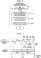
- FIG. 2 is a flowchart illustrating one example of a carrier wave generation routine executed by the electronic control unit 50. This routine is executed at times of appearance of respective extreme values (maximum values and minimum values) of the carrier wave (at a point in time when each of the first to Ne-th unit components in each unit interval ends).
- the electronic control unit 50 determines whether a point in time when this cycle of the routine is executed is one cycle before a point in time when the current unit interval ends, which will be called "the end point of the current unit interval" (step S100).
- the "end point of the current unit interval” means an end point of the Ne-th unit component in the current unit interval.
- the "point in time that is one cycle before the end point of the current unit interval” means an end point of the (Ne-1)-th unit component in the current unit interval. If the electronic control unit 50 determines that the point in time when this cycle of the routine is executed is not one cycle before the end point of the current unit interval, this cycle of the routine ends.
- step S100 If the electronic control unit 50 determines in step S100 that the point in time when this cycle of the routine is executed is one cycle before the end point of the current unit interval, it calculates the number Ne of the unit components in the next unit interval, according to Eq. (1) above (step S110). Then, the electronic control unit 50 sets times (durations) Tc[1] to Tc[Ne] of the first to Ne-th unit components in the next unit interval (step S120), and generates carrier wave for the next unit interval, based on the times Tc[1] to Tc[Ne] of the first to Ne-th unit components set in step S120 (step S130). Then, this cycle of the routine ends.
- step S120 times Tc[1] to Tc[Ne] of the first to Ne-th unit components in the next unit interval are set, such that the 60-degree required time T60 in the next unit interval is equal to the total time ⁇ Tc[1]+...+Tc[Ne]) of the first to Ne-th unit components, and times of at least two unit components, out of the times Tc[1] to Tc[Ne] of the first to Ne-th unit components in the next unit interval, differ from each other, while the times Tc[1] to Tc[Ne] of the unit components change irregularly.
- the times Tc[1] to Tc[Ne] of the first to Ne-th unit components can be set (computed), by multiplying a value (T60/Ne) obtained by dividing the 60-degree required time T60 of the next unit interval by the number Ne of the unit components, by coefficients k[1], ..., k[Ne] that are irregularly arranged, where the average of these coefficients k[1], ..., k[Ne] is equal to 1, and at least two of the coefficients are different from each other.
- time Tc[i] of the "i"-th unit component in each unit interval can be changed irregularly, even when the 60-degree required time T60 and the number Ne of the unit components are constant in two or more consecutive unit intervals.
- making times of at least two unit components, out of the times Tc[1] to Tc[Ne] of the first to Ne-th unit components, different from each other, and irregularly changing the times Tc[1] to Tc[Ne] of the unit components are equivalent to making frequencies of at least two unit components, out of frequencies Fc[1] - Fc[Ne] of the first to Ne-th unit components, or absolute values of the slopes of at least two unit components, out of absolute values of the slopes Sc[1] to Sc[Ne], different from each other, and irregularly changing the frequencies Fc[1] to Fc[Ne] or absolute values of the slopes Sc[1] to Sc[Ne] of the unit components.
- frequencies Fc[1] to Fc[Ne] or slopes Sc[1] to Sc[Ne] of the first to Ne-th unit components in the next unit interval may be set, and a carrier wave for the next unit interval may be generated using the set frequencies Fc[1] to Fc[Ne] or slopes Sc[1] to Sc[Ne].
- the time Tc of each unit component has a correlation to its electric angular width ⁇ ew. Accordingly, making the 60-degree required time T60 equal to the total time (Tc[1]+...+Tc[Ne]) of the first to Ne-th unit components is equivalent to making the width of 60 degrees in electric angle equal to the total electric angular width ( ⁇ ew[1]+...+ ⁇ ew[Ne]) of the first to Ne-th unit components.
- making the times of at least two unit components, out of the times Tc[1] to Tc[Ne] of the first to Ne-th unit components, different from each other, and irregularly changing the times Tc[1] to Tc[Ne] of the unit components are equivalent to making the electric angular widths of at least two unit components, out of electric angular widths ⁇ ew[1] to ⁇ ew[Ne] of the first to Ne-th unit components, different from each other, and irregularly changing electric angular widths ⁇ ew[1] to ⁇ ew[Ne] of the unit components.
- the electric angular widths ⁇ ew[1] to ⁇ ew[Ne] of the first to Ne-th unit components in the next unit interval may be set, and a carrier wave for the next unit interval may be generated using the set electric angular widths ⁇ ew[1] to ⁇ ew[Ne].
- the carrier wave may be generated by performing the carrier wave generation routine of FIG. 2 on at least one unit interval, and making the times Tc[1] to Tc[Ne] of the first to Ne-th unit components constant, with respect to the other unit intervals.
- FIG. 3 shows one example of the manner of generating a carrier wave.
- FIG. 3 shows the case where the synchronous number Ns is constant, and is equal to 12 (the number Ne of unit components in each unit interval is equal to 4).
- 0, 60, and 120 degrees in electric angle ⁇ e indicate zero-crossing electric angles of respective phases, and end electric angles of the last unit interval, current unit interval, and the next unit interval, and times t10, t12, and t13 indicate respective zero-crossing points in time, and end points in time of the last unit interval, current unit interval, and the next unit interval.
- the end electric angle and end point of each unit interval are set to coincide with a corresponding zero-crossing electric angle and a corresponding zero-crossing point, respectively.
- the electronic control unit 50 sets times Tc[1] to Tc[4] of the first to fourth unit components in the next unit interval, such that the 60-degree required time T60[k+1] in the next unit interval becomes equal to the total time (Tc[1]+...+Tc[4]) of the first to fourth unit components, and the times of at least two unit components, out of the times Tc[1] to Tc[4] of the first to fourth unit components in the next unit interval, differ from each other, while the times Tc[1] to Tc[Ne] of the unit components change irregularly.
- a carrier wave for the next unit interval is generated, using the set times Tc[1] to Tc[4].
- the times Tc[1] to Tc[4] correspond to frequencies Fc[1] - Fc[Ne], absolute values of slopes Sc[1] - Sc[Ne], and electric angles ⁇ ew[1] - ⁇ ew[Ne].
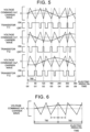
- FIG. 4 and FIG. 5 show examples of waveforms of the modulation waves Vu*, Vv*, Vw* of the voltage commands of respective phases, carrier waves, and PWM signals of the transistors T11, T12, T13.
- FIG. 4 shows the case where the synchronous number Ns is constant, and is equal to 12 (the number Ne of unit components in each unit interval is equal to 4), and
- FIG. 5 shows the case where the synchronous number Ns is constant, and is equal to 6 (the number Ne of unit components in each unit interval is equal to 2).
- 0 degree, 60 degrees, ... in electric angle ⁇ e indicate respective zero-crossing electric angles, and end electric angles in the respective unit intervals, and times t20, t21, ...
- the carrier wave is generated such that the times Tc[1] - Tc[4] (or frequencies Fc[1] - Fc[4], or absolute values of slopes Sc[1] - Sc[4], or electric angles ⁇ ew[1] - ⁇ ew[4]) of the first to fourth unit components in each unit interval differ from each other, and change irregularly.
- the carrier wave is generated such that the times Tc[1], Tc[2] (or frequencies Fc[1], Fc[2], or absolute values of slopes Sc[1], Sc[2], or electric angles ⁇ ew[1], ⁇ ew[2]) of the first and second unit components in each unit interval differ from each other, and change irregularly.
- the PWM signals of the transistors T11 - T16 can be changed irregularly.
- the number Ne of unit components in each unit interval can be set to a desired value (1/3 of the synchronous motor Ns). For example, if the rotational speed Nm of the motor 32 (or the synchronous number N based on the rotational speed Nm of the motor 32) is constant, the number Ne of unit components can be made constant. Namely, it is possible to reduce electromagnetic noise while setting the number of unit components to a desired value. With the electromagnetic noise thus reduced, the driver and passengers, and pedestrians, etc. around the vehicle, are less likely or unlikely to feel the electromagnetic noise.
- the carrier wave is generated such that the 60-degree required time T60 becomes equal to the total time (Tc[1]+...+Tc[Ne]) of the first to Ne-th unit components, in each unit interval, and the times of at least two unit components, out of the times Tc[1] to Tc[Ne] of the first to Ne-th unit components, differ from each other, while the times Tc[1] to Tc[Ne] of the unit components change irregularly, in at least one unit interval.
- making the times Tc of at least two unit components different from each other, and irregularly changing the times Tc are equivalent to making at least two frequencies Fc, or absolute values of slopes Sc, or electric angular widths ⁇ ew, different from each other, and irregularly changing the frequencies Fc, absolute values of slopes Sc, or the electric angular widths ⁇ ew.
- the carrier wave is generated such that the times Tc (or frequencies Fc, or absolute values of slopes Sc, or electric angular widths ⁇ ew) of the respective unit components change irregularly, in at least one unit interval.
- the carrier wave may be generated such that the times Tc (or frequencies Fc, or absolute values of slopes Sc, or electric angular widths ⁇ ew) of the respective unit components changes regularly. In this case, too, it is possible to prevent harmonics in given frequency bands from sticking out, and reduce electromagnetic noise, as compared with the system that makes the time Tc (or frequency Fc, or absolute value of slope Sc, or electric angular width ⁇ ew) of each unit component uniform or equal, in each unit interval.
- the carrier wave is generated such that the times Tc (or frequencies Fc, or absolute values of slopes Sc, or electric angular widths ⁇ ew) of at least two unit components differ from each other, in at least one unit interval.
- the carrier wave may be generated such that, in two consecutive unit intervals as a part of the unit intervals, the times Tc (or frequencies Fc, or absolute values of slopes Sc, or electric angular widths ⁇ ew) of unit components immediately before and after a boundary of the two unit intervals are made equal to each other.
- FIG. 6 illustrates one example of carrier wave in this case.
- the times Tc (or frequencies Fc, or absolute values of slopes Sc, or electric angular widths ⁇ ew) of m (2 ⁇ m ⁇ n) pieces of consecutive unit components in the same unit interval may be made equal to each other, in some of the unit intervals.
- FIG. 7 illustrates one example of carrier wave in this case. The inventor of this invention found that, when the time Tc of each unit component is made variable, the times Tc (or frequencies Fc, or absolute values of slopes Sc, or electric angular widths ⁇ ew) of at least two consecutive unit components are made equal to each other, so that harmonics of the frequency corresponding to the time Tc are likely to appear to some extent.
- the end electric angle and end point of each unit interval are set to coincide with the corresponding zero-crossing electric angle and the corresponding zero-crossing point, as shown in FIG. 4 and FIG. 5 .
- the end electric angle and end point of each unit interval may be set to be different from the corresponding zero-crossing electric angle and the corresponding zero-crossing point.
- FIG. 8 shows the case where the synchronous number Ns is constant, and is equal to 12 (the number Ne of unit components in each unit interval is equal to 4). In FIG. 8 , 0 degree, 60 degrees, ... in electric angle ⁇ e and times t40, t41, ...
- the electronic control unit 50 executes the carrier wave generation routine of FIG. 2 , but may execute a carrier wave generation routine of FIG. 9 , instead of that of FIG. 2 .
- the carrier wave generation routine of FIG. 9 is identical with that of FIG. 2 , except that steps S200 - S230 are added. Accordingly, the same step numbers are assigned to the same steps, of which detailed description will not be provided.
- the electronic control unit 50 determines that the point in time when this cycle of the routine is executed is not one cycle before the end point of the current unit interval, it compares the number Ne of unit components in the current unit interval with 3 (step S200). If the number Ne of unit components in the current unit interval is 3 or a greater value, the electronic control unit 50 determines whether the point in time when this cycle of the routine is executed is two cycles before the end point of the current unit interval (step S200).
- the point in time two cycles before the end point of the current unit interval means the end point in time of the (Ne-2)-th unit component in the current unit interval.
- step S200 determines that the number Ne of unit components in the current unit interval is less than 3, or step S200 determines that the number Ne of unit components in the current unit interval is equal to or greater than 3, and step S210 determines that the point in time of execution of this cycle of the routine is not two cycles before the end point of the current unit interval, this cycle of the routine ends.
- step S200 determines that the number Ne of unit components in the current unit interval is equal to or greater than 3, and step S210 determines that the point in time of execution of this cycle of the routine is two cycles before the end point of the current unit interval, the time Tc [Ne] of the Ne-th unit component in the current unit interval is reset (step S220), and the Ne-th unit component in the current unit interval is re-generated (step S230). Then, this cycle of the routine ends.
- step S220 when the number Ne of unit components in the current unit interval is equal to 3, a difference between the 60-degree required time T60 in the current unit interval, and the sum of the actual time Tca[1] of the first unit component and the time Tc[2] of the second unit component is re-set as time Tc[3] of the third unit component.
- a difference between the 60-degree required time T60, and the sum of the actual times Tca[1] to Tca[Ne-2] of the first to (Ne-2)-th unit components and the time Tc[Ne-1] of the (Ne-1)-th unit component is reset as time Tc[Ne] of the Ne-th unit component.
- the end point of the current unit interval (the end point of the Ne-th unit component) can be more appropriately determined.
- this routine is useful when the 60-degree required time T60 (the rotational speed Nm of the motor 32) varies.
- the carrier wave is generated as illustrated in FIG. 4 and FIG. 5 when the amplitudes of the modulation waves Vu*, Vv*, Vw* of the voltage commands of the respective phases are smaller than the amplitude of the carrier wave (when pseudo three-phase AC voltage is applied to the motor 32).
- the carrier wave may be generated in the same manner, when the amplitudes of the modulation waves Vu*, Vv*, Vw* of the voltage commands of the respective phases are greater than the amplitude of the carrier wave (when overmodulation voltage is applied to the motor 32).
- each unit interval has a given electric angular width (e.g., a width of 30 degrees when the number p of phases is 6) obtained by dividing one period (360 degrees in electric angle) of the modulation wave of the voltage command of each phase by twice the number p (p ⁇ 2) of phases of the motor 32.
- a capacitor may be used, in place of the battery 36.
- the boosting converter 40 is provided between the battery 36 and the inverter 34, in the drive system installed on the electric vehicle 20 of the embodiment, the boosting converter 40 may not be provided.
- the drive system is configured to be installed on the electric vehicle 20 in the embodiment, the drive system is only required to include a motor and an inverter, and the drive system may be configured to be installed on a hybrid vehicle, or may be configured to be installed on immobile equipment, such as construction equipment.
- the invention may be utilized in manufacturing industries of drive systems and automobiles, for example.
Landscapes
- Engineering & Computer Science (AREA)
- Power Engineering (AREA)
- Life Sciences & Earth Sciences (AREA)
- Sustainable Development (AREA)
- Sustainable Energy (AREA)
- Transportation (AREA)
- Mechanical Engineering (AREA)
- Inverter Devices (AREA)
- Control Of Ac Motors In General (AREA)
- Electric Propulsion And Braking For Vehicles (AREA)
Claims (10)
- Antriebssystem, umfassend:einen Mehrphasenmotor (32);einen Wechselrichter (34), der eine Vielzahl von Schaltvorrichtungen beinhaltet und konfiguriert ist, um den Motor (32) durch Schalten der Schaltvorrichtungen anzutreiben; undeine elektronische Steuereinheit (50), die konfiguriert ist, um eine Impulsbreitenmodulationssteuerung durchzuführen, wobei die Impulsbreitenmodulationssteuerung eine Steuerung ist, die Impulsbreitenmodulationssignale der Vielzahl von Schaltvorrichtungen erzeugt, indem sie eine Modulationswelle eines Spannungsbefehls jeder Phase, der auf einem Drehmomentbefehl des Motors (32) basiert, mit einer Trägerwelle vergleicht, und ein Schalten der Vielzahl von Schaltvorrichtungen durchführt,dadurch gekennzeichnet, dassdie elektronische Steuereinheit (50) konfiguriert ist, um die Trägerwelle zu erzeugen, um die Bedingungen i) und ii) wie folgt zu erfüllen, wobei eine Einheitskomponente ein Segment der Trägerwelle zwischen zwei aufeinanderfolgenden Extremwerten ist und ein Einheitsintervall ein Intervall mit einer gegebenen elektrischen Winkelbreite ist, das durch Teilen einer Periode der Modulationswelle des Spannungsbefehls durch die doppelte Anzahl von Phasen des Motors erlangt wird, während sich die Trägerwelle über eine Vielzahl von Einheitsintervallen erstreckt,i) in jedem der Einheitsintervalle ist eine erforderliche Zeit in dem Einheitsintervall gleich wie die Gesamtzeit einer Vielzahl von Einheitskomponenten, undii) in mindestens einem der Einheitsintervalle sind die Dauern von mindestens zwei Einheitskomponenten der Vielzahl von Einheitskomponenten voneinander verschieden,wobei die elektronische Steuereinheit (50) konfiguriert ist, um die Trägerwelle zu erzeugen, sodass jeder Nulldurchgangszeitpunkt, an dem die Modulationswelle des Spannungsbefehls einer der Phasen eine Nullachse durchquert, mit einem Endzeitpunkt von jedem der Einheitsintervalle zusammenfällt, und wobeidie Anzahl der Phasen des Motors (32) 3 ist, und die erforderliche Zeit in dem Einheitsintervall eine Zeitperiode ist, die erforderlich ist, damit der Motor (32) um 60 Grad in dem elektrischen Winkel dreht.
- Antriebssystem nach Anspruch 1, wobei
die elektronische Steuereinheit (50) konfiguriert ist, um die Trägerwelle zu erzeugen, sodass die Anzahl der Einheitskomponenten in zwei aufeinanderfolgenden Einheitsintervallen der Vielzahl von Einheitsintervallen konstant ist. - Antriebssystem nach Anspruch 1 oder 2, wobei
die elektronische Steuereinheit (50) konfiguriert ist, um die Trägerwelle zu erzeugen, sodass in zwei aufeinanderfolgenden Einheitsintervallen der Vielzahl von Einheitsintervallen die Dauern der Einheitskomponenten unmittelbar vor und nach einer Grenze der zwei aufeinanderfolgenden Einheitsintervalle einander gleich sind. - Antriebssystem nach Anspruch 1 oder 2, wobei
die elektronische Steuereinheit (50) konfiguriert ist, um die Trägerwelle zu erzeugen, sodass in mindestens einem Teil der Einheitsintervalle, in denen die Anzahl der Einheitskomponenten jeweils gleich wie eine erste vorbestimmte Anzahl ist, die Dauern einer zweiten vorbestimmten Anzahl aufeinanderfolgender Einheitskomponenten in demselben Einheitsintervall einander gleich sind, wobei die erste vorbestimmte Anzahl 3 oder größer ist und die zweite vorbestimmte Anzahl gleich wie oder größer als 2 und kleiner als die erste vorbestimmte Anzahl ist. - Antriebssystem nach einem der Ansprüche 1 bis 3, wobei
die elektronische Steuereinheit (50) konfiguriert ist, um die Trägerwelle zu erzeugen, sodass sich die Dauer der Einheitskomponente in demselben Einheitsintervall unregelmäßig ändert. - Antriebssystem, umfassend:einen Mehrphasenmotor (32);einen Wechselrichter (34), der eine Vielzahl von Schaltvorrichtungen beinhaltet und konfiguriert ist, um den Motor (32) durch Schalten der Schaltvorrichtungen anzutreiben; undeine elektronische Steuereinheit (50), die konfiguriert ist, um eine Impulsbreitenmodulationssteuerung durchzuführen, wobei die Impulsbreitenmodulationssteuerung eine Steuerung ist, die Impulsbreitenmodulationssignale der Vielzahl von Schaltvorrichtungen erzeugt, indem sie eine Modulationswelle eines Spannungsbefehls jeder Phase, der auf einem Drehmomentbefehl des Motors (32) basiert, mit einer Trägerwelle vergleicht, und ein Schalten der Vielzahl von Schaltvorrichtungen durchführt,dadurch gekennzeichnet, dassdie elektronische Steuereinheit (50) konfiguriert ist, um die Trägerwelle zu erzeugen, um die Bedingungen i) und ii) wie folgt zu erfüllen, wobei eine Einheitskomponente ein Segment der Trägerwelle zwischen zwei aufeinanderfolgenden Extremwerten ist und ein Einheitsintervall ein Intervall mit einer gegebenen elektrischen Winkelbreite ist, das durch Teilen einer Periode der Modulationswelle des Spannungsbefehls durch die doppelte Anzahl von Phasen des Motors erlangt wird, während sich die Trägerwelle über eine Vielzahl von Einheitsintervallen erstreckt,i) in jedem der Einheitsintervalle ist eine erforderliche Zeit in dem Einheitsintervall gleich wie die Gesamtzeit einer Vielzahl von Einheitskomponenten, undii) in mindestens einem der Einheitsintervalle sind die Frequenzen von mindestens zwei Einheitskomponenten der Vielzahl von Einheitskomponenten voneinander verschieden,wobei die elektronische Steuereinheit (50) konfiguriert ist, um die Trägerwelle zu erzeugen, sodass jeder Nulldurchgangszeitpunkt, an dem die Modulationswelle des Spannungsbefehls einer der Phasen eine Nullachse durchquert, mit einem Endzeitpunkt von jedem der Einheitsintervalle zusammenfällt, und wobeidie Anzahl der Phasen des Motors (32) 3 ist, und die erforderliche Zeit in dem Einheitsintervall eine Zeitperiode ist, die erforderlich ist, damit der Motor (32) um 60 Grad in dem elektrischen Winkel dreht.
- Antriebssystem, umfassend:einen Mehrphasenmotor (32);einen Wechselrichter (34), der eine Vielzahl von Schaltvorrichtungen beinhaltet und konfiguriert ist, um den Motor (32) durch Schalten der Schaltvorrichtungen anzutreiben; undeine elektronische Steuereinheit (50), die konfiguriert ist, um eine Impulsbreitenmodulationssteuerung durchzuführen, wobei die Impulsbreitenmodulationssteuerung eine Steuerung ist, die Impulsbreitenmodulationssignale der Vielzahl von Schaltvorrichtungen erzeugt, indem sie eine Modulationswelle eines Spannungsbefehls jeder Phase, der auf einem Drehmomentbefehl des Motors (32) basiert, mit einer Trägerwelle vergleicht, und ein Schalten der Vielzahl von Schaltvorrichtungen durchführt,dadurch gekennzeichnet, dassdie elektronische Steuereinheit (50) konfiguriert ist, um die Trägerwelle zu erzeugen, um die Bedingungen i) und ii) wie folgt zu erfüllen, wobei eine Einheitskomponente ein Segment der Trägerwelle zwischen zwei aufeinanderfolgenden Extremwerten ist und ein Einheitsintervall ein Intervall mit einer gegebenen elektrischen Winkelbreite ist, das durch Teilen einer Periode der Modulationswelle des Spannungsbefehls durch die doppelte Anzahl von Phasen des Motors erlangt wird, während sich die Trägerwelle über eine Vielzahl von Einheitsintervallen erstreckt,i) in jedem der Einheitsintervalle ist eine erforderliche Zeit in dem Einheitsintervall gleich wie die Gesamtzeit einer Vielzahl von Einheitskomponenten, undii) in mindestens einem der Einheitsintervalle sind die absoluten Werte der Steigungen von mindestens zwei Einheitskomponenten der Vielzahl von Einheitskomponenten voneinander verschieden,wobei die elektronische Steuereinheit (50) konfiguriert ist, um die Trägerwelle zu erzeugen, sodass jeder Nulldurchgangszeitpunkt, an dem die Modulationswelle des Spannungsbefehls einer der Phasen eine Nullachse durchquert, mit einem Endzeitpunkt von jedem der Einheitsintervalle zusammenfällt, und wobeidie Anzahl der Phasen des Motors (32) 3 ist, und die erforderliche Zeit in dem Einheitsintervall eine Zeitperiode ist, die erforderlich ist, damit der Motor (32) um 60 Grad in dem elektrischen Winkel dreht.
- Antriebssystem, umfassend:einen Mehrphasenmotor (32);einen Wechselrichter (34), der eine Vielzahl von Schaltvorrichtungen beinhaltet und konfiguriert ist, um den Motor (32) durch Schalten der Schaltvorrichtungen anzutreiben; undeine elektronische Steuereinheit (50), die konfiguriert ist, um eine Impulsbreitenmodulationssteuerung durchzuführen, wobei die Impulsbreitenmodulationssteuerung eine Steuerung ist, die Impulsbreitenmodulationssignale der Vielzahl von Schaltvorrichtungen erzeugt, indem sie eine Modulationswelle eines Spannungsbefehls jeder Phase, der auf einem Drehmomentbefehl des Motors (32) basiert, mit einer Trägerwelle vergleicht, und ein Schalten der Vielzahl von Schaltvorrichtungen durchführt,dadurch gekennzeichnet, dassdie elektronische Steuereinheit (50) konfiguriert ist, um die Trägerwelle zu erzeugen, um die Bedingungen i) und ii) wie folgt zu erfüllen, wobei eine Einheitskomponente ein Segment der Trägerwelle zwischen zwei aufeinanderfolgenden Extremwerten ist und ein Einheitsintervall ein Intervall mit einer gegebenen elektrischen Winkelbreite ist, das durch Teilen einer Periode der Modulationswelle des Spannungsbefehls durch die doppelte Anzahl von Phasen des Motors erlangt wird, während sich die Trägerwelle über eine Vielzahl von Einheitsintervallen erstreckt,i) in jedem der Einheitsintervalle ist eine erforderliche Zeit in dem Einheitsintervall gleich wie die Gesamtzeit einer Vielzahl von Einheitskomponenten, undii) in mindestens einem der Einheitsintervalle sind die elektrischen Winkelbreiten von mindestens zwei Einheitskomponenten der Vielzahl von Einheitskomponenten voneinander verschieden,wobei die elektronische Steuereinheit (50) konfiguriert ist, um die Trägerwelle zu erzeugen, sodass jeder Nulldurchgangszeitpunkt, an dem die Modulationswelle des Spannungsbefehls einer der Phasen eine Nullachse durchquert, mit einem Endzeitpunkt von jedem der Einheitsintervalle zusammenfällt, und wobeidie Anzahl der Phasen des Motors (32) 3 ist, und die erforderliche Zeit in dem Einheitsintervall eine Zeitperiode ist, die erforderlich ist, damit der Motor (32) um 60 Grad in dem elektrischen Winkel dreht.
- Kraftfahrzeug (20), in dem das Antriebssystem nach einem der Ansprüche 1 bis 8 installiert ist, wobei das Kraftfahrzeug konfiguriert ist, um unter Verwendung von Leistung von dem Motor (32) zu fahren.
- Verfahren zum Steuern eines Antriebssystems,wobei das Antriebssystem einen mehrphasigen Motor (32), einen Wechselrichter (34), der eine Vielzahl von Schaltvorrichtungen beinhaltet und konfiguriert ist, um den Motor (32) durch Schalten der Schaltvorrichtungen anzutreiben, und eine elektronische Steuereinheit (50), die konfiguriert ist, um eine Impulsbreitenmodulationssteuerung durchzuführen, beinhaltet, wobei die Impulsbreitenmodulationssteuerung eine Steuerung ist, die Impulsbreitenmodulationssignale der Vielzahl von Schaltvorrichtungen erzeugt, indem sie eine Modulationswelle eines Spannungsbefehls jeder Phase, der auf einem Drehmomentbefehl des Motors (32) basiert, mit einer Trägerwelle vergleicht, und ein Schalten der Vielzahl von Schaltvorrichtungen durchführt,wobei das Verfahren gekennzeichnet ist durch;Erzeugen der Trägerwelle durch die elektronische Steuereinheit (50), um die Trägerwelle zu erzeugen, um die Bedingungen i) und ii) wie folgt zu erfüllen, wobei eine Einheitskomponente ein Segment der Trägerwelle zwischen zwei aufeinanderfolgenden Extremwerten ist und ein Einheitsintervall ein Intervall mit einer gegebenen elektrischen Winkelbreite ist, das durch Teilen einer Periode der Modulationswelle des Spannungsbefehls durch die doppelte Anzahl von Phasen des Motors erlangt wird, während sich die Trägerwelle über eine Vielzahl von Einheitsintervallen erstreckt,i) in jedem der Einheitsintervalle ist eine erforderliche Zeit in dem Einheitsintervall gleich wie die Gesamtzeit einer Vielzahl von Einheitskomponenten, undii) in mindestens einem der Einheitsintervalle sind die Dauern von mindestens zwei Einheitskomponenten der Vielzahl von Einheitskomponenten voneinander verschieden,wobei die Trägerwelle von der elektronischen Steuereinheit (50) erzeugt wird, sodass jeder Nulldurchgangszeitpunkt, an dem die Modulationswelle des Spannungsbefehls einer der Phasen eine Nullachse durchquert, mit einem Endzeitpunkt von jedem der Einheitsintervalle zusammenfällt, und wobeidie Anzahl der Phasen des Motors (32) 3 ist, und die erforderliche Zeit in dem Einheitsintervall eine Zeitperiode ist, die erforderlich ist, damit der Motor (32) um 60 Grad in dem elektrischen Winkel dreht.
Applications Claiming Priority (1)
| Application Number | Priority Date | Filing Date | Title |
|---|---|---|---|
| JP2017089411A JP6812896B2 (ja) | 2017-04-28 | 2017-04-28 | 駆動装置および自動車 |
Publications (2)
| Publication Number | Publication Date |
|---|---|
| EP3396853A1 EP3396853A1 (de) | 2018-10-31 |
| EP3396853B1 true EP3396853B1 (de) | 2024-11-20 |
Family
ID=62067534
Family Applications (1)
| Application Number | Title | Priority Date | Filing Date |
|---|---|---|---|
| EP18169592.5A Active EP3396853B1 (de) | 2017-04-28 | 2018-04-26 | Antriebssystem, automobil und verfahren zur steuerung des antriebssystems |
Country Status (6)
| Country | Link |
|---|---|
| US (1) | US10348234B2 (de) |
| EP (1) | EP3396853B1 (de) |
| JP (1) | JP6812896B2 (de) |
| KR (1) | KR102126759B1 (de) |
| CN (1) | CN108809190B (de) |
| RU (1) | RU2701481C1 (de) |
Families Citing this family (2)
| Publication number | Priority date | Publication date | Assignee | Title |
|---|---|---|---|---|
| JP7542981B2 (ja) * | 2020-04-09 | 2024-09-02 | 三菱重工サーマルシステムズ株式会社 | インバータ制御装置、インバータ制御方法、及びインバータ制御プログラム |
| JP7465153B2 (ja) * | 2020-06-02 | 2024-04-10 | 株式会社Subaru | 制御装置 |
Family Cites Families (14)
| Publication number | Priority date | Publication date | Assignee | Title |
|---|---|---|---|---|
| SU1201997A1 (ru) * | 1983-03-21 | 1985-12-30 | Отдел Энергетической Кибернетики Ан Мсср | Устройство дл управлени инвертором с широтно-импульсной модул цией |
| JPH0947026A (ja) * | 1995-07-25 | 1997-02-14 | Mitsubishi Electric Corp | Pwm波形生成装置 |
| JP2000184729A (ja) * | 1998-12-17 | 2000-06-30 | Meidensha Corp | Pwmインバータの変調方法 |
| CN1177405C (zh) * | 2002-08-20 | 2004-11-24 | 艾默生网络能源有限公司 | 脉宽调制方法和装置 |
| JP4974457B2 (ja) | 2004-12-17 | 2012-07-11 | 株式会社日立製作所 | Pwmインバータの制御装置 |
| JP4729526B2 (ja) * | 2007-03-29 | 2011-07-20 | トヨタ自動車株式会社 | 電動機の駆動制御装置 |
| JP5304894B2 (ja) | 2009-05-29 | 2013-10-02 | トヨタ自動車株式会社 | 交流電動機の制御装置および制御方法 |
| JP5549384B2 (ja) * | 2010-06-03 | 2014-07-16 | 日産自動車株式会社 | 電動機の制御装置および電動機制御システム |
| JP5549887B2 (ja) * | 2011-05-19 | 2014-07-16 | アイシン・エィ・ダブリュ株式会社 | 回転電機制御装置 |
| RU2517298C2 (ru) * | 2011-11-22 | 2014-05-27 | Федеральное государственное унитарное предприятие Производственное объединение "Север" | Способ управления инвертором напряжения с широтно-импульсной модуляцией в составе системы генерирования электрической энергии переменного тока |
| RU2482595C1 (ru) * | 2011-12-19 | 2013-05-20 | Общество с ограниченной ответственностью "СИБНАНОТЕХ" | Способ управления преобразователем частоты |
| WO2014192373A1 (ja) * | 2013-05-27 | 2014-12-04 | 株式会社東芝 | 電力変換装置、電力変換装置の制御方法、回転センサレス制御装置及び回転センサレス制御装置の制御方法 |
| JP2015033263A (ja) * | 2013-08-05 | 2015-02-16 | トヨタ自動車株式会社 | インバータの制御装置 |
| JP2016005370A (ja) * | 2014-06-17 | 2016-01-12 | 株式会社東芝 | 電力変換装置 |
-
2017
- 2017-04-28 JP JP2017089411A patent/JP6812896B2/ja active Active
-
2018
- 2018-04-23 RU RU2018114892A patent/RU2701481C1/ru active
- 2018-04-24 US US15/960,649 patent/US10348234B2/en active Active
- 2018-04-25 KR KR1020180047772A patent/KR102126759B1/ko active Active
- 2018-04-26 CN CN201810383815.0A patent/CN108809190B/zh active Active
- 2018-04-26 EP EP18169592.5A patent/EP3396853B1/de active Active
Also Published As
| Publication number | Publication date |
|---|---|
| EP3396853A1 (de) | 2018-10-31 |
| US20180316298A1 (en) | 2018-11-01 |
| RU2701481C1 (ru) | 2019-09-26 |
| JP6812896B2 (ja) | 2021-01-13 |
| KR102126759B1 (ko) | 2020-06-25 |
| BR102018008038A2 (pt) | 2018-11-21 |
| US10348234B2 (en) | 2019-07-09 |
| CN108809190B (zh) | 2021-11-09 |
| CN108809190A (zh) | 2018-11-13 |
| JP2018191377A (ja) | 2018-11-29 |
| KR20180121386A (ko) | 2018-11-07 |
Similar Documents
| Publication | Publication Date | Title |
|---|---|---|
| EP2131489B1 (de) | Antriebssteuerung und antriebssteuerverfahren eines motors | |
| EP2393200A1 (de) | Steuerung für einen wechselstrommotor | |
| EP2060434A2 (de) | Motorsteuervorrichtung und Steuervorrichtung für hybride elektrische Fahrzeuge | |
| CN108964543B (zh) | 驱动装置及驱动装置的控制方法 | |
| CN107342722B (zh) | 车辆及用于车辆的控制方法 | |
| CN107453670B (zh) | 汽车 | |
| US10826410B2 (en) | Inverter device and electric vehicle | |
| CN108540040B (zh) | 驱动装置 | |
| CN108696230B (zh) | 驱动装置和驱动系统 | |
| CN103904980B (zh) | 车辆和用于车辆的控制装置 | |
| US10348234B2 (en) | Drive system, automobile, and method of controlling drive system | |
| CN108206662B (zh) | 驱动系统和用于驱动系统的控制方法 | |
| JP5691955B2 (ja) | 駆動装置 | |
| JP2018143054A (ja) | 車両 | |
| JP6751496B2 (ja) | 駆動装置 | |
| JP6332015B2 (ja) | 駆動装置 | |
| JP2014075937A (ja) | 駆動装置および電動車両 | |
| US20260091687A1 (en) | Electric vehicle | |
| JP6828297B2 (ja) | 自動車 | |
| JP6766538B2 (ja) | 駆動装置 | |
| CN103872958B (zh) | Ac电动机的控制系统 | |
| WO2023037579A1 (ja) | インバータ制御装置、電動パワーステアリングシステム、電動車両システム | |
| CN103872958A (zh) | Ac电动机的控制系统 |
Legal Events
| Date | Code | Title | Description |
|---|---|---|---|
| PUAI | Public reference made under article 153(3) epc to a published international application that has entered the european phase |
Free format text: ORIGINAL CODE: 0009012 |
|
| STAA | Information on the status of an ep patent application or granted ep patent |
Free format text: STATUS: REQUEST FOR EXAMINATION WAS MADE |
|
| 17P | Request for examination filed |
Effective date: 20180426 |
|
| AK | Designated contracting states |
Kind code of ref document: A1 Designated state(s): AL AT BE BG CH CY CZ DE DK EE ES FI FR GB GR HR HU IE IS IT LI LT LU LV MC MK MT NL NO PL PT RO RS SE SI SK SM TR |
|
| AX | Request for extension of the european patent |
Extension state: BA ME |
|
| RAP1 | Party data changed (applicant data changed or rights of an application transferred) |
Owner name: DENSO CORPORATION |
|
| STAA | Information on the status of an ep patent application or granted ep patent |
Free format text: STATUS: EXAMINATION IS IN PROGRESS |
|
| 17Q | First examination report despatched |
Effective date: 20210211 |
|
| GRAP | Despatch of communication of intention to grant a patent |
Free format text: ORIGINAL CODE: EPIDOSNIGR1 |
|
| STAA | Information on the status of an ep patent application or granted ep patent |
Free format text: STATUS: GRANT OF PATENT IS INTENDED |
|
| RIC1 | Information provided on ipc code assigned before grant |
Ipc: H02P 21/00 20160101ALN20240620BHEP Ipc: H02P 6/14 20160101ALI20240620BHEP Ipc: H02P 27/08 20060101AFI20240620BHEP |
|
| INTG | Intention to grant announced |
Effective date: 20240712 |
|
| GRAS | Grant fee paid |
Free format text: ORIGINAL CODE: EPIDOSNIGR3 |
|
| GRAA | (expected) grant |
Free format text: ORIGINAL CODE: 0009210 |
|
| STAA | Information on the status of an ep patent application or granted ep patent |
Free format text: STATUS: THE PATENT HAS BEEN GRANTED |
|
| AK | Designated contracting states |
Kind code of ref document: B1 Designated state(s): AL AT BE BG CH CY CZ DE DK EE ES FI FR GB GR HR HU IE IS IT LI LT LU LV MC MK MT NL NO PL PT RO RS SE SI SK SM TR |
|
| REG | Reference to a national code |
Ref country code: GB Ref legal event code: FG4D |
|
| REG | Reference to a national code |
Ref country code: CH Ref legal event code: EP |
|
| REG | Reference to a national code |
Ref country code: DE Ref legal event code: R096 Ref document number: 602018076664 Country of ref document: DE |
|
| REG | Reference to a national code |
Ref country code: IE Ref legal event code: FG4D |
|
| REG | Reference to a national code |
Ref country code: LT Ref legal event code: MG9D |
|
| REG | Reference to a national code |
Ref country code: NL Ref legal event code: MP Effective date: 20241120 |
|
| PG25 | Lapsed in a contracting state [announced via postgrant information from national office to epo] |
Ref country code: IS Free format text: LAPSE BECAUSE OF FAILURE TO SUBMIT A TRANSLATION OF THE DESCRIPTION OR TO PAY THE FEE WITHIN THE PRESCRIBED TIME-LIMIT Effective date: 20250320 Ref country code: PT Free format text: LAPSE BECAUSE OF FAILURE TO SUBMIT A TRANSLATION OF THE DESCRIPTION OR TO PAY THE FEE WITHIN THE PRESCRIBED TIME-LIMIT Effective date: 20250320 Ref country code: HR Free format text: LAPSE BECAUSE OF FAILURE TO SUBMIT A TRANSLATION OF THE DESCRIPTION OR TO PAY THE FEE WITHIN THE PRESCRIBED TIME-LIMIT Effective date: 20241120 |
|
| PG25 | Lapsed in a contracting state [announced via postgrant information from national office to epo] |
Ref country code: FI Free format text: LAPSE BECAUSE OF FAILURE TO SUBMIT A TRANSLATION OF THE DESCRIPTION OR TO PAY THE FEE WITHIN THE PRESCRIBED TIME-LIMIT Effective date: 20241120 Ref country code: NL Free format text: LAPSE BECAUSE OF FAILURE TO SUBMIT A TRANSLATION OF THE DESCRIPTION OR TO PAY THE FEE WITHIN THE PRESCRIBED TIME-LIMIT Effective date: 20241120 |
|
| REG | Reference to a national code |
Ref country code: AT Ref legal event code: MK05 Ref document number: 1744490 Country of ref document: AT Kind code of ref document: T Effective date: 20241120 |
|
| PG25 | Lapsed in a contracting state [announced via postgrant information from national office to epo] |
Ref country code: BG Free format text: LAPSE BECAUSE OF FAILURE TO SUBMIT A TRANSLATION OF THE DESCRIPTION OR TO PAY THE FEE WITHIN THE PRESCRIBED TIME-LIMIT Effective date: 20241120 |
|
| PG25 | Lapsed in a contracting state [announced via postgrant information from national office to epo] |
Ref country code: ES Free format text: LAPSE BECAUSE OF FAILURE TO SUBMIT A TRANSLATION OF THE DESCRIPTION OR TO PAY THE FEE WITHIN THE PRESCRIBED TIME-LIMIT Effective date: 20241120 |
|
| PG25 | Lapsed in a contracting state [announced via postgrant information from national office to epo] |
Ref country code: NO Free format text: LAPSE BECAUSE OF FAILURE TO SUBMIT A TRANSLATION OF THE DESCRIPTION OR TO PAY THE FEE WITHIN THE PRESCRIBED TIME-LIMIT Effective date: 20250220 |
|
| PG25 | Lapsed in a contracting state [announced via postgrant information from national office to epo] |
Ref country code: LV Free format text: LAPSE BECAUSE OF FAILURE TO SUBMIT A TRANSLATION OF THE DESCRIPTION OR TO PAY THE FEE WITHIN THE PRESCRIBED TIME-LIMIT Effective date: 20241120 Ref country code: GR Free format text: LAPSE BECAUSE OF FAILURE TO SUBMIT A TRANSLATION OF THE DESCRIPTION OR TO PAY THE FEE WITHIN THE PRESCRIBED TIME-LIMIT Effective date: 20250221 Ref country code: AT Free format text: LAPSE BECAUSE OF FAILURE TO SUBMIT A TRANSLATION OF THE DESCRIPTION OR TO PAY THE FEE WITHIN THE PRESCRIBED TIME-LIMIT Effective date: 20241120 |
|
| PG25 | Lapsed in a contracting state [announced via postgrant information from national office to epo] |
Ref country code: PL Free format text: LAPSE BECAUSE OF FAILURE TO SUBMIT A TRANSLATION OF THE DESCRIPTION OR TO PAY THE FEE WITHIN THE PRESCRIBED TIME-LIMIT Effective date: 20241120 |
|
| PG25 | Lapsed in a contracting state [announced via postgrant information from national office to epo] |
Ref country code: RS Free format text: LAPSE BECAUSE OF FAILURE TO SUBMIT A TRANSLATION OF THE DESCRIPTION OR TO PAY THE FEE WITHIN THE PRESCRIBED TIME-LIMIT Effective date: 20250220 |
|
| PG25 | Lapsed in a contracting state [announced via postgrant information from national office to epo] |
Ref country code: SM Free format text: LAPSE BECAUSE OF FAILURE TO SUBMIT A TRANSLATION OF THE DESCRIPTION OR TO PAY THE FEE WITHIN THE PRESCRIBED TIME-LIMIT Effective date: 20241120 |
|
| PGFP | Annual fee paid to national office [announced via postgrant information from national office to epo] |
Ref country code: DE Payment date: 20250422 Year of fee payment: 8 |
|
| PG25 | Lapsed in a contracting state [announced via postgrant information from national office to epo] |
Ref country code: DK Free format text: LAPSE BECAUSE OF FAILURE TO SUBMIT A TRANSLATION OF THE DESCRIPTION OR TO PAY THE FEE WITHIN THE PRESCRIBED TIME-LIMIT Effective date: 20241120 |
|
| PG25 | Lapsed in a contracting state [announced via postgrant information from national office to epo] |
Ref country code: EE Free format text: LAPSE BECAUSE OF FAILURE TO SUBMIT A TRANSLATION OF THE DESCRIPTION OR TO PAY THE FEE WITHIN THE PRESCRIBED TIME-LIMIT Effective date: 20241120 |
|
| PGFP | Annual fee paid to national office [announced via postgrant information from national office to epo] |
Ref country code: FR Payment date: 20250425 Year of fee payment: 8 |
|
| PG25 | Lapsed in a contracting state [announced via postgrant information from national office to epo] |
Ref country code: RO Free format text: LAPSE BECAUSE OF FAILURE TO SUBMIT A TRANSLATION OF THE DESCRIPTION OR TO PAY THE FEE WITHIN THE PRESCRIBED TIME-LIMIT Effective date: 20241120 |
|
| PG25 | Lapsed in a contracting state [announced via postgrant information from national office to epo] |
Ref country code: SK Free format text: LAPSE BECAUSE OF FAILURE TO SUBMIT A TRANSLATION OF THE DESCRIPTION OR TO PAY THE FEE WITHIN THE PRESCRIBED TIME-LIMIT Effective date: 20241120 |
|
| PG25 | Lapsed in a contracting state [announced via postgrant information from national office to epo] |
Ref country code: CZ Free format text: LAPSE BECAUSE OF FAILURE TO SUBMIT A TRANSLATION OF THE DESCRIPTION OR TO PAY THE FEE WITHIN THE PRESCRIBED TIME-LIMIT Effective date: 20241120 |
|
| PG25 | Lapsed in a contracting state [announced via postgrant information from national office to epo] |
Ref country code: IT Free format text: LAPSE BECAUSE OF FAILURE TO SUBMIT A TRANSLATION OF THE DESCRIPTION OR TO PAY THE FEE WITHIN THE PRESCRIBED TIME-LIMIT Effective date: 20241120 |
|
| REG | Reference to a national code |
Ref country code: DE Ref legal event code: R097 Ref document number: 602018076664 Country of ref document: DE |
|
| PG25 | Lapsed in a contracting state [announced via postgrant information from national office to epo] |
Ref country code: SE Free format text: LAPSE BECAUSE OF FAILURE TO SUBMIT A TRANSLATION OF THE DESCRIPTION OR TO PAY THE FEE WITHIN THE PRESCRIBED TIME-LIMIT Effective date: 20241120 |
|
| PLBE | No opposition filed within time limit |
Free format text: ORIGINAL CODE: 0009261 |
|
| STAA | Information on the status of an ep patent application or granted ep patent |
Free format text: STATUS: NO OPPOSITION FILED WITHIN TIME LIMIT |
|
| 26N | No opposition filed |
Effective date: 20250821 |
|
| REG | Reference to a national code |
Ref country code: CH Ref legal event code: H13 Free format text: ST27 STATUS EVENT CODE: U-0-0-H10-H13 (AS PROVIDED BY THE NATIONAL OFFICE) Effective date: 20251125 |
|
| PG25 | Lapsed in a contracting state [announced via postgrant information from national office to epo] |
Ref country code: LU Free format text: LAPSE BECAUSE OF NON-PAYMENT OF DUE FEES Effective date: 20250426 |
|
| PG25 | Lapsed in a contracting state [announced via postgrant information from national office to epo] |
Ref country code: MC Free format text: LAPSE BECAUSE OF FAILURE TO SUBMIT A TRANSLATION OF THE DESCRIPTION OR TO PAY THE FEE WITHIN THE PRESCRIBED TIME-LIMIT Effective date: 20241120 |
|
| REG | Reference to a national code |
Ref country code: BE Ref legal event code: MM Effective date: 20250430 |
|
| PG25 | Lapsed in a contracting state [announced via postgrant information from national office to epo] |
Ref country code: BE Free format text: LAPSE BECAUSE OF NON-PAYMENT OF DUE FEES Effective date: 20250430 |
|
| PG25 | Lapsed in a contracting state [announced via postgrant information from national office to epo] |
Ref country code: CH Free format text: LAPSE BECAUSE OF NON-PAYMENT OF DUE FEES Effective date: 20250430 |
|
| PGFP | Annual fee paid to national office [announced via postgrant information from national office to epo] |
Ref country code: GB Payment date: 20260306 Year of fee payment: 9 |
|
| PG25 | Lapsed in a contracting state [announced via postgrant information from national office to epo] |
Ref country code: IE Free format text: LAPSE BECAUSE OF NON-PAYMENT OF DUE FEES Effective date: 20250426 |