EP3395703A1 - Verfahren und vorrichtung zum applizieren von packhilfsmitteln - Google Patents
Verfahren und vorrichtung zum applizieren von packhilfsmitteln Download PDFInfo
- Publication number
- EP3395703A1 EP3395703A1 EP17020177.6A EP17020177A EP3395703A1 EP 3395703 A1 EP3395703 A1 EP 3395703A1 EP 17020177 A EP17020177 A EP 17020177A EP 3395703 A1 EP3395703 A1 EP 3395703A1
- Authority
- EP
- European Patent Office
- Prior art keywords
- packaging
- application
- transfer
- aids
- speed
- Prior art date
- Legal status (The legal status is an assumption and is not a legal conclusion. Google has not performed a legal analysis and makes no representation as to the accuracy of the status listed.)
- Granted
Links
Images




Classifications
-
- B—PERFORMING OPERATIONS; TRANSPORTING
- B65—CONVEYING; PACKING; STORING; HANDLING THIN OR FILAMENTARY MATERIAL
- B65B—MACHINES, APPARATUS OR DEVICES FOR, OR METHODS OF, PACKAGING ARTICLES OR MATERIALS; UNPACKING
- B65B61/00—Auxiliary devices, not otherwise provided for, for operating on sheets, blanks, webs, binding material, containers or packages
- B65B61/20—Auxiliary devices, not otherwise provided for, for operating on sheets, blanks, webs, binding material, containers or packages for adding cards, coupons or other inserts to package contents
- B65B61/205—Auxiliary devices, not otherwise provided for, for operating on sheets, blanks, webs, binding material, containers or packages for adding cards, coupons or other inserts to package contents for adding drinking straws to a container
Definitions
- the invention relates to a device for the separate application of supplied as a continuous packaging tape auxiliary packaging aids, preferably repackaged straws, on packages, especially cardboard composite packages, with a separating member for separating the packaging auxiliary of the auxiliary packaging tape endless, a supply means for supplying the auxiliary packaging tape endless band to the separating member and for passing on the packaging aids separated by the separating means, an application means for applying the separated packaging aids to the packs and a transport means for transporting the packs along a packing transport path to the application means.
- the invention additionally relates to a method for the separate application of packaging aids supplied as a continuous packaging aid, preferably wrapped straws, to packages, in particular cardboard composite packages.
- Packaged goods are packed by means of packaging.
- Packaged goods and packaging together form a pack.
- Particular flowable products such as drinks or other foods
- Composite packings are formed from interconnected packaging materials.
- Cardboard composite packages have, in addition to the packaging material cardboard, for example, the packaging material plastic.
- Cardboard and plastic are connected to one another over a wide area and form as a layer structure a so-called packing laminate.
- the cardboard layer gives the package stability and serves as a carrier layer for plastic layers.
- Plastic layers serve inter alia as liquid barriers, so that packaged goods such as flowable products, such as drinks, can be filled and so that no moisture can penetrate from the outside into the cardboard layer.
- plastic layers can be sealed as thermoplastic layers.
- the layer structure of the package laminate may vary depending on requirements. For example, for aseptic filling materials an additional aluminum layer is inserted to achieve a good barrier against gases and light. To be able to fold the sheet-like package laminate, ie to be able to fold it by machine, scorings are often introduced into the package laminate. Grooves define the later fold lines. The folds form the package edges on the package and / or allow the formation of package bottom and / or package head. Packaging laminates are also usually printed with a decor.
- the package laminate is cut to the interval of a package during its manufacture.
- Such blanks can be further processed into so-called packing jacket blanks.
- the blank is folded over and connected by a longitudinal sealing seam to a tube.
- pack jacket blanks form the actual packaging of a cardboard composite pack.
- the package laminate can be provided as a continuous material, in particular as a roll product.
- the actual shaping and filling of the packaging and the closing of a package takes place in a packaging machine which not infrequently, based on its main functions, in particular the shaping of the packaging, the filling of the packaging and the sealing of the packaging, also as a form / fill / Seal machine is called.
- fillings are mainly liquid foods such as drinks, soups or yogurt in question.
- stacked, pasty and lumpy products or flowable products with lumpy proportions which may also be preferably food.
- the cardboard composite packages are also referred to as beverage carton composite packages.
- Packs of the type mentioned are sometimes also provided with packaging aids such as pouring elements and / or straws, which are also referred to as drinking straws.
- the latter are usually - in order to ensure the required hygiene - added in sealed outer packaging.
- the Packaging aids may, for example, be glued to a side wall of a cardboard composite package by means of hot glue. If the consumer wants to consume the product with a straw, he first removes the over-wrapped straw from the side wall of the pack, in particular the cardboard composite pack, and peels it from the outer packaging. The exposed straw can then be at the sharpened end in a specially weakened area in the pack, in particular the cardboard composite pack, encounter, so that the product can be consumed directly over the straw.
- packaging aids are commercially available as endless belts.
- a packaging auxiliary endless belt is generally constructed from a multiplicity of packing aids which are connected to one another in the band direction, from which packing aids are separated or singulated in sequence and then applied to the packs.
- packing aids are separated or singulated in sequence and then applied to the packs.
- straw endless belts for example, these are formed by straws oriented transversely to the direction of the belt and welded in foil. The film forms both the respective outer packaging of the straws and - in their sequence - the "endless" band.
- the straw-endless belt is fed from a supply roll over guide rollers in a clocked driven feeding means to supply the endless belt a separating member for separating the straws and to pass the scattered straws to an application agent.
- the repackaged straws are separated in the feeder by means of a reciprocating cutting blade and further spent in the direction of the application site.
- the filled and sealed cardboard composite packages are meanwhile provided by a transport along a linear transport path with adhesive and fed to an application means. From the application agent, the isolated straws are applied at the application site by means of a transmission element to the supplied packages.
- the timing of Feeding means allows separation of the straws at their stoppage. However, this intermittent procedure does not often limit the processing speeds.
- the European patent EP 1042 172 B1 proposes a device for applying overpacked straws to carton composite packages wherein the endless belt is fed to a continuously rotating supply means where the separation of the straws from the endless belt is accomplished by severing the endless belt by means of a release agent.
- the feeding means first feeds the endless belt, in order then to separate the straws by means of a separating means in the form of a cutting knife.
- the cutting blade additionally performs a tracking movement over a certain peripheral portion of the feed means.
- the thus isolated straws are passed on to an application agent in the form of a likewise continuously moving application fork, from which the straws are pressed against the previously provided with adhesive and brought up via a transport along a transport path packs.
- Partial over the circumference of the feeding means accompanying release agent are mechanically complex and relatively prone to failure. Often they also produce unsatisfactory cutting results such as protruding Trennbrauen or the like.
- a transfer means for taking over the supplied from the feeding means and auxiliary means for accelerating the acquired Packaging aid is provided to a speed adapted to the application means.
- a transfer means interposed between the supply and application means permits a functional and constructional decoupling of the separation of the packaging aids from the endless packaging aid band and the application of the separated packaging aids to the packages.
- the separation of the packaging aids and the application of the packaging aids to the packages can be carried out with different speeds and according to requirements. Specifically, this means that z. B. Cutting and separating processes can be performed at lower speeds or even at standstill of the packaging auxiliary endless belt, while the application process of the individual packaging aids can be performed on the packages at higher speeds.
- Such customizable speeds result in more stable and therefore more reliable work processes and higher manufacturing qualities.
- the transfer means as a bridging member also allows a safe removal of the packaging aids from the place of separation to the place of application even at the highest application speeds.
- the transfer means can take over the separated packaging aids directly from the supply means and / or transfer them directly to the application means.
- the supply means and the application agent are then coupled directly via the transfer means, so that further modules are dispensable.
- this also means that the packaging aids are taken over at one point, the transfer position, of the transfer means and transferred to the application agent at another point, the transfer position, of the transfer means.
- the transfer and transfer preferably take place one after the other, in particular alternately, in order to be able to realize the transfer and the transfer at different speeds.
- the transfer means can be accelerated or decelerated as a whole.
- the transfer means can be braked and, if necessary, another portion of the transfer means can be accelerated.
- carriers for receiving the packaging aids which can be braked and accelerated independently of one another, can be provided. The carriers are then braked, for example, before the takeover of the packaging aids and accelerated before the transfer of the packaging aids.
- the transfer agent is accelerated or decelerated as a whole, a so-called smoldering operation comes into question.
- the transfer means can rotate slowly or even stand still and take over from the delivery means a packaging aid. Then, the supply means can be accelerated to transfer the packaging aid or another packaging aid at a higher speed to the application agent, after which the transfer agent is decelerated again to take over a further packaging aid.
- the packaging aids can be transported in the horizontal and / or vertical direction.
- the can Packaging aids for example, along a curved, circular arc or straight transport path are moved by the transfer means.
- the transport may be accomplished, for example, by a belt, a chain, individual carriers or by the movement of the transfer means as a whole.
- the supply means is fed with a continuous packaging aid, which comprises the packaging aids in sequence.
- the feeding means feeds the endless packaging auxiliary tape to a separating member which separates the endless packaging auxiliary tape while separating and separating the individual packing aids of the endless packaging auxiliary tape.
- the now individually and separately present packing aids are transported away from the supply means of the separating member and to a transfer means.
- the transfer means takes over the packaging aids at a position spaced from the separating member at a low speed or, if necessary, also at a speed of zero.
- the packaging aids are transported further by the transfer means in the direction of an application agent, wherein the packaging aids are accelerated prior to transfer to the application agent, in order then to be transferred from the transfer means to the application means at the higher speed compared to the speed when adopting the packaging aids.
- This higher speed is tuned to the speed of the application agent being moved to apply the packaging aids to packages that are moved past the application means along a transport path along a package transport path and meanwhile receive the singulated packaging aids.
- the supply means for the stepwise transport of the packaging aids is designed clocked driven. Since the individual packaging aids on the continuous packaging material endless belt typically follow at fixed intervals, it makes sense to perform the delivery as well in time intervals. Thus, a working cycle adapted to the packaging aids makes it possible to carry out further work processes. In this way, a very accurate and reproducible feeding of the packaging aids can be achieved. Alternatively or additionally, it is achieved in a simple manner such that the separation of the packaging aids from the packaging auxiliary endless belt can take place while the endless belt or the supply means is stationary or moves only at low speed.
- the steps of separation and feeding can be optimally coordinated. In this way, a very accurate and reproducible separation of the packaging aids can be achieved, which can take place if necessary, while the endless belt or the supply means is stationary or moves only at low speed. This leads to a trouble-free separation and separation of the packaging aids, so that malfunctions are minimized.
- the timing of the separating member may be that the separating member is repeatedly reciprocated in opposite directions. However, the timing may also preferably be such that the separating member is stopped in a spaced from the packaging auxiliary endless belt end position for a short period. For the reliability and the process control, it is also particularly useful if the separating member can be driven clocked synchronously with the feed.
- the supply means is preferably designed as or comprising a rotatable carousel with receptacles distributed over the circumference for transporting the packaging aids to the separating member and for passing on the packaging aids.
- a rotation axis rotatable frames, which are also referred to as carousels, make it possible, over the circumference, in particular evenly, distributed recordings for to provide the packaging aids.
- the receptacles are advantageously designed corresponding to the shape of the packaging aids, so that the receptacles can receive the packaging aids in a form-fitting manner and hold them appropriately.
- the diameter and pitch, ie the number of shots taken on the circumference, of the carousel can be adjusted to the working processes in such a way that the performance and function of the device are improved. Furthermore, but also the transport of the packaging aids is very easy and reliable possible, which can be required space savings.
- Constructively advantageous radial notches for receiving the separating member when separating the packing aids are incorporated between the receptacles, so that the separating member, for example in the form of a cutting knife, dive during the singulation process briefly in the notch and can cut through the packaging auxiliary endless belt, while preferably the adjacent packaging aids are recorded positively in the recordings.
- the packaging aid endless belt has a certain bias, which simplifies the separation of the packaging aids and improves the quality and safety of the separation.
- the application agent may alternatively or additionally have a drivable application wheel.
- the packaging aids can be transported precisely and quickly to the place of application without the need for increased expenditure on equipment. This is especially the case when the application wheel can be driven at a substantially constant rotational speed.
- the reliability of the application is improved if the peripheral speed of the application wheel at least substantially corresponds to the transport speed of the packages along the transport path at the location of the application.
- a low relative speed between the packages and the packaging aids when applying the same can be ensured, so that a process-stable application with less waste is possible.
- Become as constant as possible Speeding speeds minimize unwanted forces resulting from accelerations.
- the transfer means has a transfer element which can be pivoted at varying speeds and / or a transfer wheel which can be rotated at varying peripheral speeds. Varying velocities of the transfer means adapted to the circumstances improve the robustness of the processes, in particular also when taking over and transferring the packaging aids through the transfer means. Finally, the takeover of the packaging aids at a suitable speed of the transfer agent and the transfer of the packaging aids at another suitable speed of the transfer means can be carried out, for example, to optimize the overall process.
- the carousel and the transfer means are particularly advantageously designed so that for the transfer of the packaging aid from the carousel to the transfer means the carousel and the transfer means are at least approximately stationary or move only at low speed.
- Such a configuration increases the process reliability and avoids disturbances when adopting the packaging aid.
- At least one adhesive application means for gluing the packs supplied to the application agent along the package transport path may be assigned to the transport means. If the adhesive is applied directly to the packages in a separate process step, unwanted sticking of functional groups and assemblies is prevented and thus a stable operation of the device is achieved.
- the feed means and the transfer means are driven in a clocked manner.
- the same can apply to the transfer means if the transfer of the packaging aids by the transfer means takes place when the transfer means is at a standstill. Otherwise, the speed of the transfer means can be cyclically increased and reduced again without causing the transfer means to come to a standstill.
- the application agent preferably moves continuously, in particular with at least substantially constant speed. The speed is also preferably quite high to allow for a large throughput of packages. This is easily and reliably possible if the application medium between two applications does not have to be decelerated and accelerated each time.
- the supply means is stationary when separating the packaging aids with the separating member and / or during the transfer of the packaging aids, at least one standstill of the feeding means, in particular at each standstill of the supply means, a separation of a packaging auxiliary. If the takeover of the packaging aid from the transfer means takes place with slow movement of the supply means, the transfer of the packaging aids can each take place briefly before or after the stop of the supply means, during which the speed of the supply means is low anyway. Thus, in any case, the operation is simplified and the supply must not be stopped so often.
- the transfer means may receive the passed-on individual packing aids directly or indirectly from the supply means.
- the former is structurally easier to accomplish and can be done at a takeover position, which may be the same for all packaging tools.
- the supply means may transfer the separated packaging aids to the transfer means, wherein the transfer may take place while the delivery means and the transfer means are moving, in particular rotating.
- turning the simplicity of the movement can be regarded as a movement about a rotation axis half.
- turning may also be considered moving along a closed path, which path may be circular, but need not be.
- the feed means is formed by a carousel or the feed means comprises a carousel which rotates at a cyclically varying speed about a central axis of rotation.
- the transfer means may be formed as a transfer wheel or have a transfer wheel. The transfer wheel then preferably rotates at a cyclically varying speed about a central axis of rotation. The axes of rotation are preferably aligned parallel to each other to unify the rotational movements.
- the carousel and the transfer wheel can be moved with at least substantially the same peripheral speed when a packing aid is taken over, so that the packaging aid has an at least substantially constant speed during the transfer.
- the application agent may represent or comprise an application wheel.
- the application agent can be easily moved at a constant speed by the application wheel is set in constant rotation.
- the rotation or the circumferential speed of the application wheel is then at least substantially the same in a simple manner when taking over the packaging aids and when applying the packaging aids.
- the packaging aids are thus moved by the application wheel, if necessary, at a constant speed from the location of the takeover of the packaging aids to the location of the application.
- the transfer wheel is accelerated by the supply means to the peripheral speed of the application wheel after taking over a packaging auxiliary.
- the packaging aid can then be passed on from the transfer wheel to the application wheel at least substantially without changing the speed.
- the packaging aids at a speed, in particular peripheral speed, from the transfer means to the Pass on application agent that corresponds at least substantially the speed, in particular peripheral speed, with which the packaging aids are applied to the packs. This is easy and reliable possible.
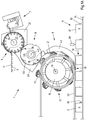
- the Fig. 1A shows a device 1 for applying packaging aids 2 in the form of repackaged straws 3, to already filled and sealed packages 4, in the form of cardboard composite packages, which are presently formed as beverage carton composite packages.
- the packaging aids 2 are in the form of a Packing aids endless belts 5 fed from a supply means 6 in the device 1, which supplies the packaging auxiliary endless belt 5 a separator 7.
- the separating device 7 separates the packaging auxiliary endless belt 5 into individual packing aids 2, which are transported by the feeding means 6 further to a transfer means 8, from which the packing aids 2 are taken over individually and successively. This takeover of the packaging aids 2 takes place at a low speed of the transfer means 8 or the packaging aids 2.
- Elsewhere the packing aids 2 are transferred from the transfer means 8 to an application means 9, wherein the transfer means 8 has been accelerated in the meantime, so that the transfer of the Packaging aid 2 to the application means 9 at a significantly higher speed.
- the application means 9 applies the packaging auxiliary 2 passed on by the transfer means 8 to the application means 9 in an application position 19 in succession to the packages 4 transported past the application position 19.
- the transport of the packages 4 along a packing transport path 10 and past the application means 9 takes place with the aid of a transport means 11.
- the packs 4 are transported by the transport means 11 at a constant speed on the application means 9, in particular at the application position 19.
- the illustrated and so far preferred transport means 11 has for this purpose provided with a cam 13 transport belt 14 which extends in the transport direction of the packs 4.
- the individual cams 13 are positively engaged with the packs 4 and move the packs 4 at defined intervals and at a defined speed along the application means 9.
- the application means 9 is designed in the illustrated preferred embodiment as an application wheel 1, which has a plurality of applicators 17 rotating about the axis of rotation 16 of the application wheel 15 and uniformly distributed over the circumference of the application wheel 15.
- the applicators 17 take on a transfer position 18 each have a packaging aid 2 and spend this to the application position 19 to apply it there to a previously transported package 4.
- the connection between the packaging aid 2 and 4 pack is given in the illustrated embodiment by an adhesive connection, with other compounds are conceivable.
- the adhesive used is hot glue, which is applied selectively to the sides 12 of the packs 4 by adhesive application means 20, in particular in the form of adhesive application nozzles, arranged on a package transport path 10.
- adhesive application means 20 in particular in the form of adhesive application nozzles, arranged on a package transport path 10.
- a packaging aid 2 is pressed into the hot glue dots.
- a pressure belt 22 presses directly from the application position 19 over a certain distance the freshly applied packaging aid 2 against the packs 4, while the packs 4 are transported on.
- the packaging aids 2 are supplied to the device 1 in the form of a packaging auxiliary endless belt 5, which is partially in the Fig. 1B is shown in more detail, and applied after a separation of packages 4.
- the packaging aids 2 are composed of a straw 3 and two foils 23 together. As straws 3 different shapes come into question, but in particular it is at least partially U-shaped or I-shaped straws 3.
- the illustrated and so far preferred packaging auxiliary endless belt 5 comprises U-shaped straws 3.
- the films 23 are at their Edges welded 24 and form a pocket 25 in between, in which the straw 3 is received. In other words, the straw 3 is repackaged in film 23.
- the packaging aid endless belt 5 is formed by a juxtaposition of the packaging aid 2, wherein in each case the films of adjacent packaging aids 2 are interconnected.
- the straws 3 are received between two foils extending along the entire auxiliary packaging tape 5.
- the packaging auxiliary endless belt 5 represents an "endless" sequence of packaging auxiliary units.
- a pack 4 with one attached thereto applied and separated from the packaging auxiliary endless belt 5 packaging aid 2 is in the Fig. 1C exemplified.
- the packaging aid 2 is applied approximately diagonally to the associated side 12 of the pack 4, which, however, does not necessarily have to be the case.
- the illustrated and insofar preferred packs 4 have a flowable food, especially a drink.
- the package 4 is a cardboard composite package, thus a beverage carton composite package.
- the packaging is formed from a packaging laminate comprising layers of different packaging materials, namely at least cardboard and plastic.
- the plastic layers are provided on the outer sides of the package laminate and formed by thermoplastics, in particular polyethylene (PE).
- PE polyethylene
- the feed means 6 comprises a carousel 27 which rotates clockwise about a central axis of rotation 26 and has receptacles 28 distributed over its circumference for partially receiving 28 the packaging aids 2.
- the receptacles 28 are modeled on the shapes of the straws 3, so that the straws 3 and thus the packaging aids 2 are held in a form-fitting manner in the receptacles 28. So that the packaging aids 2 remain in the receptacles 28, a stationary side wall 21 is circumferentially provided.
- a torsionsfederbelastetes clamping plate 30 is provided, which carries the packaging auxiliary endless belt 5 circumferentially and presses against the carousel 27 and into the receptacles 28.
- the clamping plate 30 is seen in the transport direction of the packaging auxiliary endless belt 5 seen in the side wall 21 via. If a new packaging auxiliary endless belt 5 is to be inserted, the tensioning plate 30 can be pivoted outwards and locked in order to simplify the insertion of the auxiliary packaging aid belt 5.
- the illustrated and so far preferred supply means 6 is through the carousel 27 with the receptacles 28, the side wall 21 and the clamping plate 30 is formed.
- the separating means 31 is in the illustrated and so far preferred device 1 with a drive mechanism 32 radially at least substantially in the direction of the axis of rotation 26 of the carousel 27 is moved back and forth, as indicated by the double arrow.
- the separating element 31 is designed as a sharpened cutting blade on the edge 33 associated with the auxiliary packaging aid 5 and cuts through the endless packaging aid 5 in the connecting region of two successive packaging aids 2, whereby the packaging aids 2 of the continuous packaging aid 5 are successively separated from one another.
- the separating member 31 engages at least partially in along the circumference of the carousel 27 between the receptacles 28 for the packaging aid 2 arranged notches 34 a.
- the carousel 27 operates in a timed mode in which the carousel 27 is stopped in cycles and further rotated about a circumferential segment corresponding to the width of a packaging aid 2.
- the carousel 27 is synchronized with the drive mechanism 32 of the separator 7 so that at standstill of the carousel 27, the separating member 31 is moved in the direction of the axis of rotation 26 of the carousel 27 forward and back to the starting position.
- the separating member 31 cuts through the auxiliary packaging aid band 5 in the region of the associated notch 34.
- the carousel 27 rotates in one further clock to the next position further, whereby the separating member 31 of the next notch 34 faces and can be separated by an adjustment to the front of the next packaging aid 2 from the packaging auxiliary endless belt 5.
- the separating device 7 is fixedly arranged on the supply means 6 and only the separating member 31 moves back and forth, in one linear and relative to the carousel 27 radial movement. A cyclic adjustment of the separating member 31 in the circumferential direction does not occur in the illustrated and so far preferred separating member 31.
- the notches 34 terminate radially in vertically extending evacuation channels 35 having a cross-section which is larger as the width of the notches 34 adjacent to the emptying channels 35.
- the separated in the manner described packing aids 2 are further transported with each additional cycle of the supply means 6 in the direction of a transfer position 36, from which the packaging aid 2 passed to the transfer means 8 and of the Transfer means 8 are taken over.
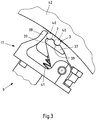
- FIG. 3 a detail of the application means 9 comprising an applicator 17 is shown.
- the outer part of the applicator 17, which moves the packaging aid 2 from the transfer position 18 into the application position 19, has an application finger 37 and a guide finger 38.
- the application finger 37 has two ends 39 on the front side, which correspond to the shape of the packaging aid 2, in particular of the straw 3.
- the two grooves 39 are used to hold the two legs 40 of the U-shaped straw 3, as shown by a dashed line packaging aid together with a straw 3.
- straws 3 basically a throat 39 would be sufficient.
- the application finger 37 is slightly pivotable against the spring force of a spring 41 and configured so that the packaging aid 2 clamped between the transfer position 18 and the application position 19 between application finger 37, guide fingers 38 and provided on the peripheral side of the application 15 squeezebande 42 and thus guided safely.
- the guide finger 38 prevents the packaging aid 2 from becoming disengaged from the application finger 37 in the circumferential direction.
- the illustrated application wheel 15 also has an adjustment mechanism (not described here in detail) which allows the packaging aids 2 to pivot about a radial axis between the transfer position 18 and the application position 19 such that the packaging aids 2 are in the transfer position 18 parallel to the axis of rotation 16 of the application wheel 15 and applied diagonally to the associated side 12 of the associated pack 4, as shown in the Fig. 1C is shown.
- the application wheel 15 rotates in the shown and thus preferred embodiment with such a constant angular velocity or peripheral speed that the packaging aids 2 and the applicators 17 frontally at the application position 19 have a peripheral speed, the amount and direction at least approximately the speed of the packs 4 correspond to the application position 19. Such operation minimizes relative speeds between package 4 and packaging aid 2 during application.
- a transfer means 8 is provided with a transfer wheel 44 rotatable about an axis of rotation 43 and a further, circumferentially provided side wall 29, as described in detail in FIG Fig. 4 is shown.
- the transfer wheel 44 has elongated receiving grooves 45 for receiving the packaging aid 2, which are arranged distributed uniformly over the circumference of the transfer wheel 44.
- the packaging aids 2 are not shown, as well as the packaging aid endless belt 5.
- the packaging aids 2 are guided between the transfer wheel 44 and the stationary further side wall 29 and are transported by the positive connection between the receiving grooves 45 and the packaging aids 2 in the circumferential direction.
- the transfer means 8 takes over the passed on Auxiliary packaging means 2 from the carousel 27 and accelerates the packaging aid 2 between transfer position 36 and the transfer position 18 to a speed adapted to the application wheel 15 and transfers the packaging aid 2 at the transfer position 18 to an applicator 17 of the application wheel 15.
- the part of the transfer means 8 is shown, which is located in the region of the transfer position 36 of the packaging aid 2 from the carousel 27 to the transfer wheel 44 of the transfer means 8.
- the carousel 27 is formed by a plurality of stacked and spaced-apart plate members 46, so that a plurality of intermediate planes 47 between the plate members 34 form.
- this intermediate planes 35 protrude as extensions of the further side wall 21 a plurality of stationary Ausklammlamellen 48.
- the Ausurammlamellen 48 form in their sum a sectional guide when taking out the packaging aid 2 from the receptacles 28 of the carousel 27, so that with the other side wall 21 the packaging aid 2 a Complete guidance when adopting the packaging aid 2 in the receiving grooves 45 of the transfer wheel 44 from the receptacles 2 of the carousel 27 is offered.
- the transfer wheel 44 When transferring the packaging aids 2, the transfer wheel 44 in the region of the grooves 45 an approximately equal, albeit small, peripheral speed as the carousel 27 in the area of the receptacles 28, so that the packaging aid 2 at least substantially free of acceleration from the supply means 6 to the transfer means 8 can be passed.
- the transfer wheel 44 is further rotated and in particular accelerated from the time from which the packaging aid 2 is received and guided between the transfer wheel 44 and the further side wall 29.
- the transfer means 8 and the application means 9 are shown in the transfer position 18.
- the transfer wheel 44 is constructed in a similar manner as the carousel 27, namely a plurality of plate elements 46, which in turn also form intermediate levels 47 into which several Auskmmlamellen protrude 49 as a continuation of the sideband 42. This makes it possible to comb out the packaging aids 2 from the receiving grooves 45 of the transfer wheel 44 in the region of the transfer position 18.
- the transfer wheel 44 and the applicator 15 have at least approximately the same peripheral speeds.
- the packaging aid 2 is held by the application finger 37 and the guide finger 38.
- the packaging aid 2 is combed out completely by the Auskarmmlamellen 49 from the receiving groove 45 and the packaging aid 2 is guided during further rotation by the side band 42 and pressed against the side band 42.
- the packaging aids 2 are transported by the applicator 15 from the transfer position 18 to the application position 19 at a constant speed and thereby pivoted about a radial axis. In the application position 19, the packaging aid 2 is then applied obliquely to the pack 4 transported past.
Landscapes
- Engineering & Computer Science (AREA)
- Mechanical Engineering (AREA)
- Auxiliary Devices For And Details Of Packaging Control (AREA)
Abstract
Description
- Die Erfindung betrifft eine Vorrichtung zum separaten Applizieren von als Packhilfsmittel-Endlosband zugeführten Packhilfsmitteln, vorzugsweise umverpackten Strohhalmen, an Packungen, insbesondere Karton-Verbundpackungen, mit einem Trennorgan zum Vereinzeln der Packhilfsmittel des Packhilfsmittel-Endlosbandes, einem Zuführmittel zum Zuführen des Packhilfsmittel-Endlosbandes zum Trennorgan und zum Weitergeben der durch das Trennorgan vereinzelten Packhilfsmittel, einem Applikationsmittel zum Applizieren der vereinzelten Packhilfsmittel an die Packungen und einem Transportmittel zum Transportieren der Packungen entlang eines Packungs-Transportpfads zum Applikationsmittel. Die Erfindung betrifft zudem ein Verfahren zum separaten Applizieren von als Packhilfsmittel-Endlosband zugeführten Packhilfsmitteln, vorzugsweise umverpackten Strohhalmen, an Packungen, insbesondere Karton-Verbundpackungen.
- Packgüter werden mittels Verpackungen verpackt. Packgut und Verpackung bilden zusammen eine Packung. Zum Abfüllen und Verpacken von insbesondere fließfähigen Produkten, wie Getränken oder anderen Lebensmitteln, werden neben Flaschen und Dosen auch Verbundpackungen verwendet. Verbundpackungen sind aus miteinander verbundenen Packstoffen gebildet. Karton-Verbundpackungen weisen neben dem Packstoff Karton beispielsweise auch den Packstoff Kunststoff auf. Karton und Kunststoff sind flächig miteinander verbunden und bilden als Schichtaufbau ein sogenanntes Packungslaminat. Die Kartonschicht verleiht der Packung Stabilität und dient als Trägerschicht für Kunststoffschichten. Kunststoffschichten dienen unter anderem als Flüssigkeitssperren, so dass Packgüter wie fließfähige Produkte, beispielsweise Getränke, abgefüllt werden können und so dass keine Feuchtigkeit von außen in die Kartonschicht eindringen kann. Ferner lassen sich Kunststoffschichten als thermoplastische Schichten siegeln. So werden beispielsweise stoffschlüssig gefügte Siegelnähte zur Ausbildung der Verpackung und zum Verschließen zur Packung möglich. Der Schichtaufbau des Packungslaminats kann je nach Anforderungen variieren. So wird beispielsweise für aseptische Füllgüter zusätzlich eine Aluminiumschicht eingelegt, um eine gute Barrierewirkung gegen Gase und Licht zu erzielen. Um das flächige Packungslaminat falzen, also maschinell falten, zu können, sind oft Rillungen in das Packungslaminat eingebracht. Rillungen definieren die späteren Falzlinien vor. Die Falzungen bilden an der Packung die Packungskanten und/oder ermöglichen die Ausformung von Packungsboden und/oder Packungskopf. Packungslaminate sind zudem meist mit einem Dekor bedruckt.
- Oft - aber nicht immer - wird das Packungslaminat noch während seiner Herstellung auf das Intervall einer Verpackung zugeschnitten. Solche Zuschnitte können zu sogenannten Packungsmantelrohlingen weiterverarbeitet werden. Dabei wird der Zuschnitt umgelegt und durch eine Längssiegelnaht zu einem Rohr verbunden. Solche Packungsmantelrohlinge bilden das eigentliche Packmittel einer Karton-Verbundpackung. Alternativ kann das Packungslaminat als Endlosmaterial, insbesondere als Rollenware, bereitgestellt werden.
- Das eigentliche Formen und Befüllen der Verpackung und das Verschließen zu einer Packung geschieht in einer Verpackungsmaschine, die nicht selten in Anlehnung an ihre Hauptfunktionen, insbesondere das Formen der Verpackung, das Füllen der Verpackung und das Siegeln der Verpackung, auch als Form-/Fill-/Seal-Maschine bezeichnet wird. Als Füllgüter kommen vorwiegend flüssige Lebensmittel wie beispielsweise Getränke, Suppen oder Joghurt in Frage. Denkbar sind auch gestockte, pastöse und stückige Produkte oder fließfähige Produkte mit stückigen Anteilen, die ebenfalls vorzugsweise Lebensmittel sein können. Im Falle von Getränken werden die Karton-Verbundpackungen auch als Getränkekarton-Verbundpackungen bezeichnet.
- Packungen genannter Art werden zuweilen auch mit Packhilfsmitteln wie beispielsweise Ausgießelementen und/oder Strohhalmen, die auch als Trinkhalme bezeichnet werden, versehen. Letztere sind in der Regel - um die gebotene Hygiene zu gewährleisten - in verschlossenen Umverpackungen aufgenommen. Die Packhilfsmittel können beispielsweise mittels Heißleim an eine Seitenwand einer Karton-Verbundpackung geklebt sein. Will der Konsument das Produkt mit einem Strohhalm verzehren, entfernt er zunächst den umverpackten Strohhalm von der Seitenwand der Packung, insbesondere der Karton-Verbundpackung, und schält diesen aus der Umverpackung. Der freigelegte Strohhalm lässt sich sodann am gespitzten Ende in einen speziell geschwächten Bereich in der Packung, insbesondere der Karton-Verbundpackung, stoßen, so dass das Produkt direkt über den Strohhalm verzehrt werden kann.
- Als Massenware sind Packhilfsmittel marktüblich als Endlosbänder verfügbar. Ein Packhilfsmittel-Endlosband ist in der Regel aus einer Vielzahl von in Bandrichtung miteinander verbundenen Packhilfsmitteln aufgebaut, von denen der Reihe nach Packhilfsmittel separiert bzw. vereinzelt und anschließend an den Packungen appliziert werden. Im Falle von Strohhalm-Endlosbändern werden diese beispielsweise durch quer zur Bandrichtung ausgerichtete und in Folie eingeschweißte Strohhalme gebildet. Die Folie bildet dabei sowohl die jeweilige Umverpackung der Strohhalme wie auch - in ihrer Abfolge - das "endlose" Band.
- Für die maschinelle Vereinzelung und Applikation der umverpackten Strohhalme an Karton-Verbundpackungen werden beispielsweise Vorrichtungen gemäß
DE 29 02 899 A1 eingesetzt. Dabei wird das Strohhalm-Endlosband von einer Vorratsrolle über Umlenkwalzen in ein getaktet angetriebenes Zuführmittel eingespeist, um das Endlosband einem Trennorgan zum Vereinzeln der Strohhalme zuzuführen und um die vereinzelten Strohhalme an ein Applikationsmittel weiterzugeben. Die umverpackten Strohhalme werden im Zuführmittel mittels eines hin und her beweglichen Schneidmessers vereinzelt und weiter in Richtung des Applikationsorts verbracht. Die gefüllten und verschlossenen Karton-Verbundpackungen werden derweil von einem Transportmittel entlang eines linearen Transportpfades mit Klebstoff versehen und einem Applikationsmittel zugeführt. Vom Applikationsmittel werden die vereinzelten Strohhalme am Applikationsort mittels eines Übertragungselements an die zugeführten Packungen appliziert. Die Taktung des Zuführmittels ermöglicht eine Vereinzelung der Strohhalme bei deren Stillstand. Dieses taktweise Vorgehen wirkt aber nicht selten limitierend auf die Verarbeitungsgeschwindigkeiten. - Das europäische Patent
EP 1042 172 B1 schlägt eine Vorrichtung zum Anbringen von umverpackten Strohhalmen an Karton-Verbundpackungen vor, wobei das Endlosband einem sich kontinuierlich drehenden Zuführmittel zugeführt wird, wo die Vereinzelung der Strohhalme vom Endlosband durch das Zertrennen des Endlosbands mittels eines Trennmittels vollzogen wird. Das Zuführmittel speist zunächst das Endlosband ein, um dann die Strohhalme mittels eines Trennmittels in Form eines Schneidmessers zu vereinzeln. Das Schneidmesser vollführt dabei neben einer radialen Stechbewegung in Richtung der Antriebsmittel-Drehachse zusätzlich eine Mitlaufbewegung über einen gewissen Umfangsabschnitt des Zuführmittels. Die so vereinzelten Strohhalme werden an ein Applikationsmittel in Form einer sich ebenfalls kontinuierlich bewegenden Applikationsgabel weitergegeben, von der die Strohhalme an die zuvor mit Klebstoff versehenen und über ein Transportmittel entlang eines Transportpfads herangeführten Packungen angedrückt werden. Teilweise über den Umfang des Zuführmittels mitlaufende Trennmittel sind mechanisch aufwändig und relativ störungsanfällig. Oft produzieren sie auch nicht zufriedenstellende Schneidergebnisse wie abstehende Trennbrauen oder dergleichen. - Davon ausgehend ist es die Aufgabe der vorliegenden Erfindung, eine Vorrichtung und ein Verfahren der eingangs genannten und zuvor näher beschriebenen Art so auszugestalten und weiterzubilden, dass die beschriebenen Nachteile überwunden werden. Insbesondere sollen das Separieren und das Applizieren von Packhilfsmitteln schnell, qualitativ hochwertig und zuverlässig erfolgen.
- Gelöst wird die Aufgabe bei einer Vorrichtung nach dem Oberbegriff von Anspruch 1 dadurch, dass ein Überführmittel zum Übernehmen der vom Zuführmittel weitergegebenen Packhilfsmittel und zum Beschleunigen der übernommenen Packhilfsmittel auf eine an das Applikationsmittel angepasste Geschwindigkeit vorgesehen ist.
- Gelöst wird die der Erfindung zugrunde liegende Aufgabe ebenfalls durch ein Verfahren gemäß Oberbegriff von Anspruch 10, bei dem folgende Arbeitsschritte ausgeführt werden:
- Zuführen eines Packhilfsmittel-Endlosbandes zu einem Trennorgan mittels eines Zuführmittels,
- Vereinzeln der Packhilfsmittel des Packhilfsmittel-Endlosbandes am Zuführmittel mittels eines Trennorgans,
- Weitergeben der vereinzelten Packhilfsmittel mittels des Zuführmittels,
- Übernehmen und Beschleunigen der vereinzelten Packhilfsmittel auf eine an ein Applikationsmittel angepasste Geschwindigkeit durch ein Überführmittel,
- Übergeben der beschleunigten Packhilfsmittel mit an das Applikationsmittel angepasster Geschwindigkeit an das Applikationsmittel und
- Applizieren der Packhilfsmittel an durch ein Transportmittel entlang eines Packungs-Transportpfades an dem Applikationsmittel vorbeibewegten Packungen mittels des Applikationsmittels.
- Ein zwischen Zuführ- und Applikationsmittel zwischengeschaltetes Überführmittel erlaubt eine funktionale und bauliche Entkoppelung des Separierens der Packhilfsmittel vom Packhilfsmittel-Endlosband und des Applizierens der separierten Packhilfsmittel an die Packungen. So können das Vereinzeln der Packhilfsmittel und das Applizieren der Packhilfsmittel an die Packungen mit unterschiedlichen und jeweils anforderungsgemäßen Geschwindigkeiten erfolgen. Konkret heißt das, dass z. B. Schneid- und Vereinzelungsprozesse bei niedrigeren Geschwindigkeiten oder gar bei Stillstand des Packhilfsmittel-Endlosbands durchgeführt werden können, während der Applikationsprozess der vereinzelten Packhilfsmittel an die Packungen bei höheren Geschwindigkeiten durchgeführt werden kann. Derart anpassbare Geschwindigkeiten führen zu stabileren und somit zuverlässigeren Arbeitsprozessen und höheren Fertigungsqualitäten. Gleichzeitig kann der Gesamtprozess beschleunigt werden. Das Überführmittel als Überbrückungsglied ermöglicht zudem ein sicheres Verbringen der Packhilfsmittel vom Ort des Separierens an den Ort des Applizierens selbst bei höchsten Applikationsgeschwindigkeiten.
- Der Einfachheit halber kann das Überführmittel die separierten Packhilfsmittel direkt vom Zuführmittel übernehmen und/oder direkt an das Applikationsmittel übergeben. Das Zuführmittel und das Applikationsmittel sind dann unmittelbar über das Überführmittel gekoppelt, so dass weitere Baugruppen entbehrlich sind. Dies bedeutet bedarfsweise auch, dass die Packhilfsmittel an einer Stelle, der Übernahmeposition, des Übergabemittels übernommen und an einer anderen Stelle, der Übergabeposition, des Übergabemittels an das Applikationsmittel übergeben wird. Dabei erfolgt das Übernehmen und das Übergeben vorzugsweise nacheinander, insbesondere abwechselnd, um die Übernahme und die Übergabe bei unterschiedlichen Geschwindigkeiten realisieren zu können. In der Zwischenzeit kann das Überführmittel insgesamt beschleunigt oder abgebremst werden. Alternativ kann auch nur ein Teil des Überführmittels abgebremst und ein, bedarfsweise anderer, Teil des Überführmittels beschleunigt werden. Es können in diesem Falle beispielsweise Träger zur Aufnahme der Packhilfsmittel vorgesehen sein, die unabhängig voneinander abgebremst und beschleunigt werden können. Die Träger werden dann beispielsweise vor der Übernahme der Packhilfsmittel abgebremst und vor der Übergabe der Packhilfsmittel beschleunigt. Wenn das Überführmittel jeweils insgesamt beschleunigt oder abgebremst wird, kommt ein sogenannter schwelender Betrieb in Frage. Dabei kann sich das Überführmittel langsam drehen oder gar stillstehen und dabei von dem Zuführmittel ein Packhilfsmittel übernehmen. Sodann kann das Zuführmittel beschleunigt werden, um das Packhilfsmittel oder ein anderes Packhilfsmittel bei höherer Geschwindigkeit an das Applikationsmittel zu übergeben, wonach das Überführmittel wieder abgebremst wird um ein weiteres Packhilfsmittel zu übernehmen.
- Je nach der Ausgestaltung des Überführmittels können die Packhilfsmittel in horizontaler und/oder vertikaler Richtung transportiert werden. Dabei können die Packhilfsmittel beispielsweise entlang einer gekrümmten, kreisbogenförmigen oder geraden Transportbahn von dem Überführmittel bewegt werden. Der Transport kann beispielsweise von einem Band, einer Kette, einzelnen Trägern oder durch die Bewegung des Überführmittels insgesamt bewerkstelligt werden.
- Verfahrensmäßig wird also zunächst dem Zuführmittel ein Packhilfsmittel-Endlosband zugeführt, das die Packhilfsmittel der Reihe nach aufweist. Das Zuführmittel führt nach der Übernahme des Packhilfsmittel-Endlosbands das Packhilfsmittel-Endlosband einem Trennorgan zu, das das Packhilfsmittel-Endlosband auftrennt und dabei die einzelnen Packhilfsmittel des Packhilfsmittel-Endlosbands separiert und vereinzelt. Die nun einzeln und separiert vorliegenden Packhilfsmittel werden von dem Zuführmittel von dem Trennorgan weg und zu einem Überführmittel hin transportiert. Das Überführmittel übernimmt die Packhilfsmittel an einer von dem Trennorgan beabstandeten Position mit einer geringen Geschwindigkeit oder bedarfsweise auch einer Geschwindigkeit von Null. Die Packhilfsmittel werden von dem Überführmittel in Richtung eines Applikationsmittels weiter transportiert, wobei die Packhilfsmittel vor der Übergabe an das Applikationsmittel beschleunigt werden, um dann mit der höheren Geschwindigkeit gegenüber der Geschwindigkeit beim Übernehmen der Packhilfsmittel vom Überführmittel an das Applikationsmittel übergeben zu werden. Diese höhere Geschwindigkeit ist abgestimmt auf die Geschwindigkeit des Applikationsmittels, das bewegt wird, um die Packhilfsmittel an Packungen zu applizieren, die über ein Transportmittel entlang eines Packungs-Transportpfads an dem Applikationsmittel vorbeibewegt werden und währenddessen die vereinzelten Packhilfsmittel empfangen.
- Der besseren Verständlichkeit halber und zur Vermeidung unnötiger Wiederholungen werden nachfolgend die Vorrichtung und das Verfahren gemeinsam beschrieben, ohne jeweils im Einzelnen zwischen der Vorrichtung und dem Verfahren zu unterscheiden. Anhand des Kontextes wird jedoch ersichtlich, welches Merkmal jeweils hinsichtlich der Vorrichtung und des Verfahrens bevorzugt ist.
- Bei einer ersten besonders bevorzugten Ausgestaltung der Vorrichtung ist das Zuführmittel zum schrittweisen Transport der Packhilfsmittel getaktet antreibbar ausgebildet. Da die einzelnen Packhilfsmittel auf dem Packhilfsmittel-Endlosband typischerweise in festen Intervallen abfolgen, ist es sinnvoll, die Zuführung ebenso in zeitlichen Intervallen vorzunehmen. So ermöglicht eine auf die Packhilfsmittel abgestimmte Arbeitstaktung die Vornahme weiterer Arbeitsprozesse. Auf diese Weise kann ein sehr genaues und reproduzierbares Zuführen der Packhilfsmittel erreicht werden. Alternativ oder zusätzlich wird so in einfacher Weise erreicht, dass das Separieren der Packhilfsmittel vom Packhilfsmittel-Endlosband erfolgen kann, während das Endlosband bzw. das Zuführmittel stillsteht oder sich nur mit geringer Geschwindigkeit bewegt.
- Wenn das Trennorgan getaktet antreibbar ausgebildet ist, lassen sich die Arbeitsschritte des Trennens und des Zuführens optimal aufeinander abstimmen. Auf diese Weise kann ein sehr genaues und reproduzierbares Trennen der Packhilfsmittel erreicht werden, das bedarfsweise erfolgen kann, während das Endlosband bzw. das Zuführmittel stillsteht oder sich nur mit geringer Geschwindigkeit bewegt. Dies führt zu einem störungsfreien Trennen und Vereinzeln der Packhilfsmittel, so dass Betriebsstörungen minimiert werden. Die Taktung des Trennorgans kann darin bestehen, dass das Trennorgan wiederholt in entgegengesetzte Richtungen hin und her bewegt wird. Die Taktung kann aber vorzugsweise auch so erfolgen, dass das Trennorgan in einer vom Packhilfsmittel-Endlosband beabstandeten Endstellung für einen kurzen Zeitraum angehalten wird. Für die Zuverlässigkeit und die Verfahrensführung ist es zudem besonders zweckmäßig, wenn das Trennorgan synchron mit dem Zuführmittel getaktet angetrieben werden kann.
- Bevorzugt ist das Zuführmittel als oder umfassend ein drehbares Karussell mit über dem Umfang verteilt angeordneten Aufnahmen für den Transport der Packhilfsmittel zum Trennorgan und zur Weitergabe der Packhilfsmittel ausgebildet. Um eine Rotationsachse drehbare Gestelle, die auch als Karusselle bezeichnet werden, ermöglichen es, über den Umfang, insbesondere gleichmäßig, verteilte Aufnahmen für die Packhilfsmittel vorzusehen. Dabei sind die Aufnahmen vorteilhafterweise korrespondierend zur Form der Packhilfsmittel ausgebildet, so dass die Aufnahmen die Packhilfsmittel formschlüssig aufnehmen und zweckmäßig halten können. Durchmesser und Teilung, d.h. die auf den Umfang bezogene Anzahl der Aufnahmen, des Karussells lassen sich so auf die Arbeitsprozesse abstimmen, dass die Leistung und Funktion der Vorrichtung verbessert werden. Des Weiteren ist aber auch der Transport der Packhilfsmittel sehr einfach und zuverlässig möglich, wobei sich bedarfsweise Bauraum einsparen lässt.
- Konstruktiv vorteilhaft sind zwischen den Aufnahmen radiale Kerben zur Aufnahme des Trennorgans beim Vereinzeln der Packhilfsmittel eingearbeitet, so dass das Trennorgan, beispielsweise in Form eines Schneidmessers, beim Vereinzelungsvorgang kurzzeitig in die Kerbe eintauchen und dabei das Packhilfsmittel-Endlosband durchtrennen kann, während vorzugsweise die angrenzenden Packhilfsmittel formschlüssig in den Aufnahmen aufgenommen sind. Auf diese Weise kann auch erreicht werden, dass das Packhilfsmittel-Endlosband eine gewisse Vorspannung aufweist, was die Vereinzelung der Packhilfsmittel vereinfacht sowie die Güte und Sicherheit der Vereinzelung verbessert.
- Das Applikationsmittel kann alternativ oder zusätzlich ein antreibbares Applikationsrad aufweisen. Durch das Applikationsrad können die Packhilfsmittel präzise und schnell an den Applikationsort herantransportiert werden, ohne dass dazu ein erhöhter apparativer Aufwand erforderlich wäre. Dies ist in besonderem Maße der Fall, wenn das Applikationsrad mit im Wesentlichen konstanter Drehgeschwindigkeit antreibbar ist. Zudem wird die Zuverlässigkeit der Applikation verbessert, wenn die Umfangsgeschwindigkeit des Applikationsrads wenigstens im Wesentlichen der Transportgeschwindigkeit der Packungen entlang des Transportpfads am Ort der Applikation entspricht. So kann eine geringe Relativgeschwindigkeit zwischen den Packungen und den Packhilfsmitteln beim Applizieren derselben sichergestellt werden, so dass eine prozessstabilere Applikation mit weniger Ausschuss möglich wird. Werden zudem möglichst konstante Geschwindigkeiten gefahren, minimieren sich unerwünschte Kräfte, die aus Beschleunigungen resultieren.
- Bei einer weiteren zweckmäßigen Ausgestaltung der Erfindung weist das Überführmittel ein mit variierenden Geschwindigkeiten schwenkbares Überführelement und/oder ein mit variierenden Umfangsgeschwindigkeiten drehbares Überführrad auf. Variierende, den Gegebenheiten anpasste Geschwindigkeiten des Überführmittels verbessern die Robustheit der Prozesse, namentlich auch bei Übernahme und Übergabe der Packhilfsmittel durch das Überführmittel. Letztlich kann die Übernahme der Packhilfsmittel bei einer geeigneten Geschwindigkeit des Überführmittels und die Übergabe der Packhilfsmittel bei einer anderen geeigneten Geschwindigkeit des Überführmittels erfolgen, um beispielsweise das Gesamtverfahren zu optimieren. So sind besonders vorteilhaft das Karussell und das Überführmittel so ausgebildet, dass zur Übergabe der Packhilfsmittel vom Karussell an das Überführmittel das Karussell und das Überführmittel wenigstens annähernd stillstehen oder sich nur mit geringer Geschwindigkeit bewegen. Eine solche Konfiguration erhöht die Prozesssicherheit und vermeidet Störungen beim Übernehmen des Packhilfsmittels.
- Alternativ oder zusätzlich kann dem Transportmittel wenigstens ein Klebstoffauftragsmittel zum Beleimen der entlang des Packungs-Transportpfads dem Applikationsmittel zugeführten Packungen zugeordnet sein. Wird der Klebstoff direkt und in einem separaten Verfahrensschritt auf die Packungen aufgebracht, wird ein unerwünschtes Verkleben von Funktions- und Baugruppen verhindert und somit ein stabiler Betrieb der Vorrichtung erreicht.
- Bei einer ersten besonders bevorzugten Ausgestaltung des Verfahrens werden das Zuführmittel und das Überführmittel getaktet angetrieben. Dies bedeutet, dass das Zuführmittel und das Überführmittel jeweils gleichartige Bewegungszyklen durchlaufen. Hinsichtlich des Zuführmittels kann dieses in regelmäßigen Abständen angehalten werden, um ein Abtrennen eines weiteren Packhilfsmittels vom Packhilfsmittel-Endlosband zu bewirken. Gleiches kann für das Überführmittel gelten, wenn das Übernehmen der Packhilfsmittel durch das Überführmittel bei Stillstand des Überführmittels erfolgt. Andernfalls kann zyklisch die Geschwindigkeit des Überführmittels gesteigert und wieder reduziert werden, ohne dass es dabei zum Stillstand des Überführmittels kommt. Alternativ oder zusätzlich bewegt sich das Applikationsmittel vorzugsweise kontinuierlich, insbesondere mit wenigstens im Wesentlichen konstanter Geschwindigkeit. Die Geschwindigkeit ist zudem vorzugsweise recht hoch um einen großen Durchsatz an Packungen zu ermöglichen. Dies ist einfach und zuverlässig möglich, wenn das Applikationsmittel zwischen zwei Applikationen nicht jedes Mal abgebremst und wieder beschleunigt werden muss.
- Wenn das Zuführmittel beim Vereinzeln der Packhilfsmittel mit dem Trennorgan und/oder bei der Weitergabe der Packhilfsmittel stillsteht, erfolgt vorzugsweise bei wenigstens einem Stillstand des Zuführmittels, insbesondere bei jedem Stillstand des Zuführmittels, eine Vereinzelung eines Packhilfsmittels. Wenn die Übernahme des Packhilfsmittels vom Überführmittel bei langsamer Bewegung des Zuführmittels erfolgt, kann die Weitergabe der Packhilfsmittel jeweils kurzzeitig vor oder nach dem Stillstand des Zuführmittels erfolgen, währenddessen die Geschwindigkeit des Zuführmittels ohnehin gering ist. Damit wird in jedem Fall der Betrieb vereinfacht und muss das Zuführmittel nicht so oft angehalten werden.
- Das Überführmittel kann die weitergegebenen vereinzelten Packhilfsmittel direkt oder indirekt vom Zuführmittel erhalten. Ersteres ist konstruktiv einfacher zu bewerkstelligen und kann an einer Übernahmeposition erfolgen, die für alle Packhilfsmittel identisch sein kann. Mit anderen Worten kann das Zuführmittel die vereinzelten Packhilfsmittel an das Überführmittel übergeben, wobei die Übergabe erfolgen kann, während sich das Zuführmittel und das Überführmittel bewegen, insbesondere drehen. Dabei kann das Drehen der Einfachheit der Bewegung halber als Bewegung um eine Drehachse herum angesehen werden. Das Drehen kann aber auch als sich entlang einer geschlossenen Bahn bewegen angesehen werden, wobei die Bahn kreisförmig sein kann, aber nicht sein muss.
- In einem konstruktiv und verfahrensmäßig einfachen Fall wird das Zuführmittel durch ein Karussell gebildet oder weist das Zuführmittel ein Karussell auf, das sich mit zyklisch variierender Geschwindigkeit um eine zentrale Drehachse dreht. Alternativ oder zusätzlich kann das Überführmittel als Überführrad ausgebildet sein oder ein Überführrad aufweisen. Das Überführrad dreht sich dann bevorzugt mit einer zyklisch variierenden Geschwindigkeit um eine zentrale Drehachse. Die Drehachsen sind zur Vereinheitlichung der Drehbewegungen vorzugsweise parallel zueinander ausgerichtet. Um die Weitergabe des Packhilfsmittels zuverlässig bewirken zu können, können das Karussell und das Überführrad bei der Übernahme eines Packhilfsmittels mit wenigstens im Wesentlichen derselben Umfangsgeschwindigkeit bewegt werden, so dass das Packhilfsmittel bei der Weitergabe eine wenigstens im Wesentlichen konstante Geschwindigkeit aufweist.
- Alternativ oder zusätzlich kann das Applikationsmittel ein Applikationsrad darstellen oder umfassen. So kann das Applikationsmittel problemlos mit einer konstanten Geschwindigkeit bewegt werden, indem das Applikationsrad in gleichbleibende Drehung versetzt wird. Die Drehung bzw. die Umfangsgeschwindigkeit des Applikationsrads ist dann in einfacher Weise bei der Übernahme der Packhilfsmittel und beim Applizieren der Packhilfsmittel wenigstens im Wesentlichen gleich. Die Packhilfsmittel werden also vom Applikationsrad bedarfsweise mit konstanter Geschwindigkeit vom Ort der Übernahme der Packhilfsmittel bis zum Ort der Applikation bewegt. Um dies ohne Weiteres erreichen zu können, wird das Überführrad nach dem Übernehmen eines Packhilfsmittels vom Zuführmittel auf die Umfangsgeschwindigkeit des Applikationsrads beschleunigt. Das Packhilfsmittel kann dann wenigstens im Wesentlichen ohne Geschwindigkeitsänderung vom Überführrad an das Applikationsrad weitergegeben werden.
- Ganz grundsätzlich und unabhängig von der Art des Überführmittels und des Applikationsmittels kann vorgesehen sein, die Packhilfsmittel mit einer Geschwindigkeit, insbesondere Umfangsgeschwindigkeit, vom Überführmittel an das Applikationsmittel weiterzugeben, die wenigstens im Wesentlichen der Geschwindigkeit, insbesondere Umfangsgeschwindigkeit, entspricht, mit der die Packhilfsmittel an die Packungen appliziert werden. Dies ist einfach und zuverlässig möglich.
- Die Erfindung ist nachfolgend anhand der ein Ausführungsbeispiel zeigenden Zeichnungen erläutert. Die Zeichnungen zeigen in:
- Fig. 1A-C
- eine erfindungsgemäße Vorrichtung in Draufsicht sowie ein Teil eines Packhilfsmittel-Endlosbands zur Verarbeitung mit der Vorrichtung und eine Packung mit einem von der Vorrichtung an die Packung applizierten Packhilfsmittel jeweils in seiner Seitenansicht,
- Fig. 2
- ein Zuführmittel der Vorrichtung aus
Fig. 1A umfassend ein Trennorgan in Draufsicht, - Fig. 3
- ein Detail eines Applikationsmittels der Vorrichtung aus
Fig. 1A in Draufsicht, - Fig. 4
- ein Detail der Vorrichtung aus
Fig. 1A im Bereich einer Übernahmeposition eines Überführmittels in perspektivischer Darstellung und - Fig. 5
- ein Detail der Vorrichtung aus
Fig. 1A im Bereich einer Übergabeposition eines Überführmittels in perspektivischer Darstellung. - Die
Fig. 1A zeigt eine Vorrichtung 1 zum Applizieren von Packhilfsmitteln 2 in Form von umverpackten Strohhalmen 3, an bereits gefüllte und verschlossene Packungen 4, in Form von Karton-Verbundpackungen, die vorliegend als Getränkekarton-Verbundpackungen ausgebildet sind. Die Packhilfsmittel 2 werden in Form eines Packhilfsmittel-Endlosbands 5 von einem Zuführmittel 6 in die Vorrichtung 1 eingezogen, die das Packhilfsmittel-Endlosband 5 einer Trenneinrichtung 7 zuführt. Die Trenneinrichtung 7 trennt das Packhilfsmittel-Endlosband 5 in einzelne Packhilfsmittel 2 auf, die von dem Zuführmittel 6 weiter zu einem Überführmittel 8 transportiert werden, von dem die Packhilfsmittel 2 einzeln und nacheinander übernommen werden. Diese Übernahme der Packhilfsmittel 2 erfolgt bei einer geringen Geschwindigkeit des Überführmittels 8 bzw. der Packhilfsmittel 2. An anderer Stelle werden die Packhilfsmittel 2 von dem Überführmittel 8 an ein Applikationsmittel 9 übergeben, wobei das Überführmittel 8 zwischenzeitlich beschleunigt worden ist, so dass die Übergabe der Packhilfsmittel 2 an das Applikationsmittel 9 bei deutlich höherer Geschwindigkeit erfolgt. - Das Applikationsmittel 9 appliziert die vom Überführmittel 8 an das Applikationsmittel 9 weitergegebenen Packhilfsmittel 2 in einer Applikationsposition 19 der Reihe nach an die an der Applikationsposition 19 vorbei transportierten Packungen 4. Der Transport der Packungen 4 entlang eines Packungs-Transportpfades 10 und vorbei an dem Applikationsmittel 9 erfolgt mit Hilfe eines Transportmittels 11. Dabei werden die Packungen 4 von dem Transportmittel 11 mit einer konstanten Geschwindigkeit am Applikationsmittel 9, insbesondere an der Applikationsposition 19, vorbei transportiert. Das dargestellte und insoweit bevorzugte Transportmittel 11 weist dazu einen mit Nocken 13 versehenen Transportriemen 14 auf, der sich in der Transportrichtung der Packungen 4 erstreckt. Die einzelnen Nocken 13 sind formschlüssig mit den Packungen 4 in Eingriff und verschieben die Packungen 4 in definierten Abständen und definierter Geschwindigkeit entlang des Applikationsmittels 9.
- Das Applikationsmittel 9 ist bei der dargestellten und insoweit bevorzugten Ausgestaltung als ein Applikationsrad 1 ausgeführt, das mehrere um die Drehachse 16 des Applikationsrad 15 rotierende und gleichmäßig über den Umfang des Applikationsrads 15 verteilt angeordnete Applikatoren 17 aufweist. Die Applikatoren 17 übernehmen an einer Übergabeposition 18 jeweils ein Packhilfsmittel 2 und verbringen dieses zur Applikationsposition 19, um es dort an eine vorbeitransportierte Packung 4 zu applizieren.
- Die Verbindung zwischen Packhilfsmittel 2 und Packung 4 ist in dem dargestellten Ausführungsbeispiel durch eine Klebeverbindung gegeben, wobei auch andere Verbindungen denkbar sind. Als Klebstoff wird Heißleim eingesetzt, der durch am ein Packungs-Transportpfad 10 angeordnetes Klebstoffauftragsmittel 20, insbesondere in Form von Klebstoffauftragsdüsen, punktuell an die Seiten 12 der Packungen 4 aufgebracht wird. An der Applikationsposition 19 wird jeweils ein Packhilfsmittel 2 in die Heißleimpunkte gedrückt. Um die so applizierten Packhilfsmittel 2 in Position zu halten und dem Heißleim eine gewisse Abbindzeit zu gewähren, drückt ein Andrückriemen 22 unmittelbar ab der Applikationsposition 19 über eine gewisse Wegstrecke die frisch applizierten Packhilfsmittel 2 gegen die Packungen 4, während die Packungen 4 weitertransportiert werden.
- Die Packhilfsmittel 2 werden der Vorrichtung 1 in Form eines Packhilfsmittel-Endlosbands 5 zugeführt, das teilweise in der
Fig. 1B näher dargestellt ist, und nach einer Vereinzelung an Packungen 4 appliziert. Die Packhilfsmittel 2 setzen sich aus einem Strohhalm 3 und zwei Folien 23 zusammen. Als Strohhalme 3 kommen dabei verschiedene Formen in Frage, insbesondere handelt es sich jedoch um wenigstens teilweise U-förmige oder I-förmige Strohhalme 3. Das dargestellte und insoweit bevorzugte Packhilfsmittel-Endlosband 5 umfasst U-förmige Strohhalme 3. Die Folien 23 sind an ihren Rändern 24 verschweißt und bilden dazwischen eine Tasche 25, in der der Strohhalm 3 aufgenommen ist. Mit anderen Worten ist der Strohhalm 3 in Folie 23 umverpackt. Das Packhilfsmittel-Endlosband 5 wird durch eine Aneinanderreihung der Packhilfsmittel 2 gebildet, wobei jeweils die Folien benachbarter Packhilfsmittel 2 miteinander verbunden sind. Beim dargestellten und insoweit bevorzugten Packhilfsmittel-Endlosband 5 sind die Strohhalme 3 zwischen zwei sich entlang des gesamten Packhilfsmittel-Endlosbands 5 erstreckenden Folien aufgenommen. Anders ausgedrückt stellt das Packhilfsmittel-Endlosband 5 eine "endlose" Abfolge von Packhilfsmitteleinheiten dar. Eine Packung 4 mit einem daran applizierten und vom Packhilfsmittel-Endlosband 5 separierten Packhilfsmittel 2 ist in derFig. 1C beispielhaft dargestellt. Das Packhilfsmittel 2 ist etwa diagonal zur zugeordneten Seite 12 der Packung 4 appliziert, was jedoch nicht zwingend der Fall sein muss. - Die dargestellten und insoweit bevorzugten Packungen 4 weisen ein fließfähiges Lebensmittel, insbesondere ein Getränk auf. Zudem handelt es sich bei der Packung 4 um eine Karton-Verbundpackung, mithin eine Getränkekarton-Verbundpackung. Die Verpackung ist aus einem Packungslaminat gebildet, das Schichten aus unterschiedlichen Packstoffen, nämlich wenigstens Karton und Kunststoff umfasst. Die Kunststoffschichten sind an den Außenseiten des Packungslaminats vorgesehen und durch thermoplastische Kunststoffe, insbesondere Polyethylen (PE), gebildet. Durch Falten und Siegeln des Packungslaminats ist die Packung 4 geformt und verschlossen. Bedarfsweise ist das Packungslaminat einseitig mit einem Dekor bedruckt.
- In der
Fig. 2 ist ein das Zuführmittel 6 umfassendes Detail der Vorrichtung 1 aus derFig. 1A dargestellt. Das Zuführmittel 6 umfasst ein sich um eine zentrale Drehachse 26 im Uhrzeigersinn drehendes Karussell 27, das über seinen Umfang verteilt Aufnahmen 28 zur teilweisen Aufnahme 28 der Packhilfsmittel 2 aufweist. Die Aufnahmen 28 sind den Formen der Strohhalme 3 nachgebildet, so dass die Strohhalme 3 und damit die Packhilfsmittel 2 formschlüssig in den Aufnahmen 28 gehalten sind. Damit die Packhilfsmittel 2 in den Aufnahmen 28 verbleiben, ist umfangsseitig eine ortsfeste Seitenwand 21 vorgesehen. Im Bereich des Einzugs des Packhilfsmittel-Endlosbandes 5 vom Zuführmittel 6 ist ein torsionsfederbelastetes Spannblech 30 vorgesehen, das das Packhilfsmittel-Endlosband 5 umfangsseitig führt und gegen das Karussell 27 und in die Aufnahmen 28 drückt. Das Spannblech 30 geht in Transportrichtung des Packhilfsmittel-Endlosbands 5 gesehen in die Seitenwand 21 über. Soll ein neues Packhilfsmittel-Endlosband 5 eingelegt werden, kann das Spannblech 30 nach außen geschwenkt und arretiert werden, um das Einlegen des Packhilfsmittel-Endlosbands 5 zu vereinfachen. Das dargestellte und insoweit bevorzugte Zuführmittel 6 wird durch das Karussell 27 mit den Aufnahmen 28, der Seitenwand 21 und dem Spannblech 30 gebildet. - Dem Zuführmittel 6 zugeordnet ist eine Trenneinrichtung 7 zur Vereinzelung der Packhilfsmittel 2 vom Packhilfsmittel-Endlosband 5 mit einem Trennorgan 31. Das Trennorgan 31 wird bei der dargestellten und insoweit bevorzugten Vorrichtung 1 mit einem Antriebsmechanismus 32 radial wenigstens im Wesentlichen in Richtung der Drehachse 26 des Karussells 27 hin und her bewegt, wie dies durch den Doppelpfeil angedeutet ist. Das Trennorgan 31 ist an der dem Packhilfsmittel-Endlosband 5 zugeordneten Kante 33 als geschärftes Schneidmesser ausgeführt und durchschneidet das Packhilfsmittel-Endlosband 5 im Verbindungsbereich zweier aufeinanderfolgender Packhilfsmittel 2, wodurch die Packhilfsmittel 2 des Packhilfsmittel-Endlosbands 5 nacheinander voneinander separiert bzw. vereinzelt werden. Dabei greift das Trennorgan 31 wenigstens teilweise in entlang des Umfangs des Karussells 27 zwischen den Aufnahmen 28 für die Packhilfsmittel 2 angeordnete Kerben 34 ein.
- Das Karussell 27 arbeitet in einem getakteten Betrieb, in dem das Karussell 27 taktweise angehalten und um ein Umfangssegment weitergedreht wird, das der Breite eines Packhilfsmittels 2 entspricht. Dazu ist das Karussell 27 mit dem Antriebsmechanismus 32 der Trenneinrichtung 7 so synchronisiert, dass bei Stillstand des Karussells 27 das Trennorgan 31 in Richtung der Drehachse 26 des Karussells 27 nach vorne und wieder zurück in die Ausgangsstellung bewegt wird. Beim Verstellen des Trennorgans 31 nach vorne durchtrennt das Trennorgan 31 das Packhilfsmittel-Endlosband 5 im Bereich der zugeordneten Kerbe 34. Sobald das Trennorgan 31 wieder außer Eingriff mit der Kerbe 34, insbesondere wieder in der Ausgangsstellung angekommen, ist, dreht das Karussell 27 in einem weiteren Takt zur nächsten Position weiter, wodurch das Trennorgan 31 der nächsten Kerbe 34 gegenübersteht und durch ein Verstellen nach vorne das nächste Packhilfsmittel 2 vom Packhilfsmittel-Endlosband 5 abtrennen kann. Die Trenneinrichtung 7 ist ortsfest am Zuführmittel 6 angeordnet und nur das Trennorgan 31 bewegt sich hin und her, und zwar in einer linearen und bezogen auf das Karussell 27 radialen Bewegung. Ein taktweises Verstellen des Trennorgans 31 in Umfangsrichtung erfolgt beim dargestellten und insoweit bevorzugten Trennorgan 31 nicht.
- Um kleinere Schneidrückstände, wie etwa Schneidbrauen, aufnehmen und/oder abführen zu können, bzw. eine ausreichende Ent- und/oder Belüftung bereitzustellen, enden die Kerben 34 in radialer Richtung in sich vertikal erstreckenden Entleerungskanälen 35, die einen Querschnitt aufweisen, welcher größer ist als die Breite der Kerben 34 angrenzend zu den Entleerungskanälen 35. Die auf die beschriebene Weise vereinzelten Packhilfsmittel 2 werden mit jedem weiteren Takt des Zuführmittels 6 weiter in Richtung einer Übernahmeposition 36 weitertransportiert, von der aus die Packhilfsmittel 2 an das Überführmittel 8 übergeben und von dem Überführmittel 8 übernommen werden.
- In der
Fig. 3 ist ein Detail des Applikationsmittels 9 umfassend einen Applikator 17 dargestellt. Der äußere Teil des Applikators 17, der das Packhilfsmittel 2 von der Übergabeposition 18 in die Applikationsposition 19 bewegt, weist einen Applikationsfinger 37 und einen Führungsfinger 38 auf. Der Applikationsfinger 37 weist stirnseitig zwei Kehlen 39 auf, die mit der Form des Packhilfsmittels 2, insbesondere des Strohhalms 3, korrespondieren. Die beiden Kehlen 39 werden zum Halten der beiden Schenkel 40 des U-förmigen Strohhalms 3 genutzt, wie dies durch ein strichliniert eingezeichnetes Packungshilfsmittel mitsamt einem Strohhalm 3 dargestellt ist. Bei Verwendung von geradlinigen, also I-förmigen, Strohhalmen 3 wäre grundsätzlich eine Kehle 39 ausreichend. Der Applikationsfinger 37 ist geringfügig gegen die Federkraft einer Feder 41 verschwenkbar und so konfiguriert, dass das Packhilfsmittel 2 zwischen der Übergabeposition 18 und der Applikationsposition 19 zwischen Applikationsfinger 37, Führungsfinger 38 und einer umfangsseitig des Applikationsrads 15 vorgesehenen Seitenbande 42 eingespannt und somit sicher geführt. Der Führungsfinger 38 verhindert dabei, dass das Packhilfsmittel 2 in Umfangsrichtung außer Eingriff mit dem Applikationsfinger 37 gerät. - Kurz vor der Applikationsposition 19 endet die Seitenbande 42, wie dies in der
Fig. 1A dargestellt ist, so dass das Packhilfsmittel 2 durch die Federkraft der Feder 41 in den Heißleim der vorbeibewegten Packung 4 gedrückt wird. Das dargestellte Applikationsrad 15 verfügt zudem über einen - hier nicht näher beschriebenen - Verstellmechanismus, der es erlaubt, die Packhilfsmittel 2 zwischen der Übergabeposition 18 und der Applikationsposition 19 derart um eine radiale Achse zu schwenken, dass die Packhilfsmittel 2 in der Übergabeposition 18 parallel zur Drehachse 16 des Applikationsrads 15 übernommen und diagonal zu der zugeordneten Seite 12 der zugeordneten Packung 4 appliziert werden können, wie dies in derFig. 1C dargestellt ist. - Das Applikationsrad 15 dreht im gezeigten und insofern bevorzugten Ausführungsbeispiel mit einer derart konstanten Winkelgeschwindigkeit bzw. Umfangsgeschwindigkeit, dass die Packhilfsmittel 2 bzw. die Applikatoren 17 stirnseitig an der Applikationsposition 19 eine Umfangsgeschwindigkeit aufweisen, die in Betrag und Richtung zumindest annähernd der Geschwindigkeit der Packungen 4 an der Applikationsposition 19 entsprechen. Ein solcher Betrieb minimiert Relativgeschwindigkeiten zwischen Packung 4 und Packhilfsmittel 2 beim Applizieren.
- Zwischen Applikationsmittel 9 und Zuführmittel 6 ist ein Überführmittel 8 mit einem um eine Drehachse 43 drehbaren Überführrad 44 und einer weiteren, umfangsseitig vorgesehenen Seitenwand 29 vorgesehen, wie dies im Detail in der
Fig. 4 dargestellt ist. Das Überführrad 44 weist längliche Aufnahmenuten 45 für die Aufnahme der Packhilfsmittel 2 auf, die gleichmäßig über den Umfang des Überführrads 44 verteilt angeordnet sind. Der besseren Übersichtlichkeit halber sind die Packhilfsmittel 2 jedoch ebenso wie das Packhilfsmittel-Endlosband 5 nicht dargestellt. Die Packhilfsmittel 2 sind zwischen dem Überführrad 44 und der ortsfesten weiteren Seitenwand 29 geführt und werden durch den Formschluss zwischen den Aufnahmenuten 45 und den Packhilfsmitteln 2 in Umfangsrichtung transportiert. In der Übernahmeposition 36 übernimmt das Überführmittel 8 das weitergegebene Packhilfsmittel 2 vom Karussell 27 und beschleunigt das Packhilfsmittel 2 zwischen Übernahmeposition 36 und der Übergabeposition 18 auf eine dem Applikationsrad 15 angepasste Geschwindigkeit und übergibt das Packhilfsmittel 2 an der Übergabeposition 18 einem Applikator 17 des Applikationsrads 15. - Neben dem Zuführmittel 6 ist der Teil des Überführmittels 8 dargestellt, der sich im Bereich der Übernahmeposition 36 des Packhilfsmittels 2 vom Karussell 27 auf das Überführrad 44 des Überführmittels 8 befindet. Das Karussell 27 ist durch eine Vielzahl gestapelter und zueinander beabstandeter Plattenelemente 46 gebildet ist, so dass sich mehrere Zwischenebenen 47 zwischen den Plattenelementen 34 ausbilden. In diese Zwischenebenen 35 ragen als Fortsätze der weiteren Seitenwand 21 mehrere ortsfeste Auskämmlamellen 48. Die Auskämmlamellen 48 bilden in ihrer Summe eine abschnittsweise Führung beim Herausführen der Packhilfsmittel 2 aus den Aufnahmen 28 des Karussells 27, so dass mit der weiteren Seitenwand 21 dem Packhilfsmittel 2 eine lückenlose Führung beim Übernehmen des Packhilfsmittels 2 in die Aufnahmenuten 45 des Überführrads 44 aus den Aufnahmen 2 des Karussells 27 geboten ist.
- Bei der Übergabe der Packhilfsmittel 2 weist das Überführrad 44 im Bereich der Aufnahmenuten 45 eine etwa gleichgroße, wenn auch geringe, Umfangsgeschwindigkeit wie das Karussell 27 im Bereich der Aufnahmen 28 auf, so dass die Packhilfsmittel 2 wenigstens im Wesentlichen beschleunigungsfrei vom Zuführmittel 6 auf das Überführmittel 8 weitergegeben werden können. Das Überführrad 44 wird weiter verdreht und insbesondere ab dem Zeitpunkt beschleunigt, ab dem das Packhilfsmittel 2 zwischen Überführrad 44 und der weiteren Seitenwand 29 aufgenommen und geführt ist.
- In der
Fig. 5 , in der der besseren Übersichtlichkeit halber ebenfalls die Packhilfsmittel 2 nicht dargestellt sind, sind das Überführmittel 8 und das Applikationsmittel 9 im Bereich der Übergabeposition 18 dargestellt. Das Überführrad 44 ist in ähnlicher Weise wie das Karussell 27 aufgebaut, nämlich aus mehreren Plattenelementen 46, die ihrerseits ebenfalls Zwischenebenen 47 bilden, in die mehrere Auskämmlamellen 49 als Fortführung der Seitenbande 42 ragen. Dies ermöglicht das Auskämmen der Packhilfsmittel 2 aus den Aufnahmenuten 45 des Überführrads 44 im Bereich der Übergabeposition 18. - Beim Übergeben des Packhilfsmittels 2 vom Überführmittel 8 auf das Applikationsmittel 9 weisen das Überführrad 44 und das Applikatorrad 15 wenigstens annähernd die gleichen Umfangsgeschwindigkeiten auf. Nach dem Übergeben wird das Packhilfsmittel 2 vom Applikationsfinger 37 und vom Führungsfinger 38 gehalten. Beim weiteren Drehen des Applikatorrads wird das Packhilfsmittel 2 durch die Auskämmlamellen 49 vollständig aus der Aufnahmenut 45 ausgekämmt und wird das Packhilfsmittel 2 beim weiteren Drehen durch die Seitenbande 42 geführt und an die Seitenbande 42 gedrückt. Die Packhilfsmittel 2 werden von dem Applikatorrad 15 von der Übergabeposition 18 bis in die Applikationsposition 19 mit einer konstanten Geschwindigkeit transportiert und dabei um eine radiale Achse geschwenkt. In der Applikationsposition 19 wird das Packhilfsmittel 2 dann schräg an die vorbeitransportierte Packung 4 appliziert.
-
- 1
- Vorrichtung
- 2
- Packhilfsmittel
- 3
- Strohhalme
- 4
- Packungen
- 5
- Packhilfsmittel-Endlosband
- 6
- Zuführmittel
- 7
- Trenneinrichtung
- 8
- Überführmittel
- 9
- Applikationsmittel
- 10
- Packungs-Transportpfad
- 11
- Transportmittel
- 12
- Seite der Packung
- 13
- Nocken
- 14
- Transportriemen
- 15
- Applikationsrad
- 16
- Drehachse
- 17
- Applikator
- 18
- Übergabeposition
- 19
- Applikationsposition
- 20
- Klebstoffauftragsmittel
- 21
- Seitenwand
- 22
- Andrückriemen
- 23
- Folie
- 24
- Rand
- 25
- Tasche
- 26
- Drehachse
- 27
- Karussell
- 28
- Aufnahmen
- 29
- Seitenwand
- 30
- Spannblech
- 31
- Trennorgan
- 32
- Antriebsmechanismus
- 33
- Kante
- 34
- Kerbe
- 35
- Entleerungskanal
- 36
- Übernahmeposition
- 37
- Applikationsfinger
- 38
- Führungsfinger
- 39
- Kehle
- 40
- Schenkel
- 41
- Feder
- 42
- Seitenbande
- 43
- Drehachse
- 44
- Überführrad
- 45
- Aufnahmenut
- 46
- Plattenelement
- 47
- Zwischenebene
- 48
- Auskämmlamelle
- 49
- Auskämmlamelle
Claims (15)
- Vorrichtung (1) zum separaten Applizieren von als Packhilfsmittel-Endlosband (5) zugeführten Packhilfsmitteln (2), vorzugsweise umverpackten Strohhalmen (3), an Packungen (4), insbesondere Karton-Verbundpackungen, mit einem Trennorgan (31) zum Vereinzeln der Packhilfsmittel (2) des Packhilfsmittel-Endlosbandes (5), einem Zuführmittel (6) zum Zuführen des Packhilfsmittel-Endlosbandes (5) zum Trennorgan (31) und zum Weitergeben der durch das Trennorgan (31) vereinzelten Packhilfsmittel (2), einem Applikationsmittel (9) zum Applizieren der vereinzelten Packhilfsmittel (2) an die Packungen (4) und einem Transportmittel (11) zum Transportieren der Packungen (4) entlang eines Packungs-Transportpfads (10) zum Applikationsmittel (9),
dadurch gekennzeichnet, dass
ein Überführmittel (8) zum Übernehmen der vom Zuführmittel (6) weitergegebenen Packhilfsmittel (2) und zum Beschleunigen der übernommenen Packhilfsmittel (2) auf eine an das Applikationsmittel (9) angepasste Geschwindigkeit vorgesehen ist. - Vorrichtung nach Anspruch 1,
dadurch gekennzeichnet, dass
das Zuführmittel (6) zum schrittweisen Transport der Packhilfsmittel (2) getaktet antreibbar ausgebildet ist. - Vorrichtung nach einem der Ansprüche 1 oder 2,
dadurch gekennzeichnet, dass
das Trennorgan (31) getaktet, insbesondere synchron mit dem Zuführmittel (6), antreibbar ausgebildet ist. - Vorrichtung nach einem der Ansprüche 1 bis 3,
dadurch gekennzeichnet, dass
das Zuführmittel (6) ein drehbares Karussell (27) mit über dem Umfang verteilt angeordneten Aufnahmen (28) für den Transport der Packhilfsmittel (2) zum Trennorgan (7) und zur Weitergabe der Packhilfsmittel (2) aufweist. - Vorrichtung nach Anspruch 4,
dadurch gekennzeichnet, dass
zwischen den Aufnahmen (28) radiale Kerben (34) zur Aufnahme des Trennorgans (31) beim Vereinzeln eingearbeitet sind. - Vorrichtung nach einem der Ansprüche 1 bis 5,
dadurch gekennzeichnet, dass
das Applikationsmittel (9) ein, vorzugsweise mit im Wesentlichen konstanter Drehgeschwindigkeit, insbesondere mit einer im Wesentlichen der Transportgeschwindigkeit der Packungen (4) entsprechenden Umfangsgeschwindigkeit, antreibbares Applikationsrad (15) aufweist. - Vorrichtung nach einem der Ansprüche 1 bis 6,
dadurch gekennzeichnet, dass
das Überführmittel (8) ein mit variierenden Geschwindigkeiten schwenkbares Überführelement und/oder ein mit variierenden Umfangsgeschwindigkeiten drehbares Überführrad (44) aufweist. - Vorrichtung nach Anspruch 7,
dadurch gekennzeichnet, dass
das Zuführmittel (6), insbesondere ein Karussell (27) des Zuführmittels (6), und das Überführmittel (8), insbesondere ein Überführrad (44) des Überführmittels (8), zur Übernahme der Packhilfsmittel (2) vom Zuführmittel (6) auf das Überführmittel (8) bei wenigstens annähernd gleicher Geschwindigkeit von Zuführmittel (6) und Überführmittel (8) an einer Übernahmeposition (36) ausgebildet sind. - Vorrichtung nach einem der Ansprüche 1 bis 8,
dadurch gekennzeichnet, dass
dem Transportmittel (11) wenigstens ein Klebstoffauftragsmittel (20) zum Beleimen der entlang des Packungs-Transportpfads (10) dem Applikationsmittel (9) zugeführten Packungen (4) zugeordnet ist. - Verfahren zum separaten Applizieren von in einem Packhilfsmittel-Endlosband (5) zugeführten Packhilfsmitteln (2), vorzugsweise umverpackten Strohhalmen (3), an Packungen (4), insbesondere Karton-Verbundpackungen, vorzugsweise mit einer Vorrichtung nach einem der Ansprüche 1 bis 9,
gekennzeichnet durch die Schritte- Zuführen eines Packhilfsmittel-Endlosbandes (5) zu einem Trennorgan (31) mittels eines Zuführmittels (6),- Vereinzeln der Packhilfsmittel (2) des Packhilfsmittel-Endlosbandes (5) am Zuführmittel (6) mittels eines Trennorgans (31),- Weitergeben der vereinzelten Packhilfsmittel (2) mittels des Zuführmittels (6),- Übernehmen und Beschleunigen der vereinzelten Packhilfsmittel (2) auf eine an ein Applikationsmittel (9) angepasste Geschwindigkeit durch ein Überführmittel (8),- Übergeben der beschleunigten Packhilfsmittel (2) mit an das Applikationsmittel (9) angepasster Geschwindigkeit an das Applikationsmittel (9) und- Applizieren der Packhilfsmittel (2) an durch ein Transportmittel (11) entlang eines Packungs-Transportpfades (10) an dem Applikationsmittel (9) vorbeibewegten Packungen (4) mittels des Applikationsmittels (9). - Verfahren nach Anspruch 10,
dadurch gekennzeichnet, dass das Zuführmittel (6) und das Überführmittel (8) getaktet angetrieben werden, und/oder dass das Applikationsmittel (9) kontinuierlich, insbesondere mit wenigstens im Wesentlichen konstanter Geschwindigkeit, angetrieben wird. - Verfahren nach Anspruch 10 oder 11,
dadurch gekennzeichnet, dass
das Zuführmittel (6) beim Vereinzeln der Packhilfsmittel (2) mit dem Trennorgan (31) und/oder bei der Weitergabe der Packhilfsmittel (2) stillsteht. - Verfahren nach einem der Ansprüche 10 bis 12,
dadurch gekennzeichnet, dass
das Überführmittel (8) die vereinzelten Packhilfsmittel (2), vorzugsweise direkt, an einer Übernahmeposition (36) vom Zuführmittel (6) übernimmt und/oder, vorzugsweise direkt, an einer Übergabeposition (18) an das Applikationsmittel (9) übergibt und/oder dass die Packhilfsmittel (2) von einem Karussell (27) des Zuführmittels (6) an ein Überführrad (44) des Übergabemittels (8), insbesondere durch Drehen des Karussells (27) und des Überführrads (44), und/oder von dem Überführrad (44) des Übergabemittels (8) an ein Applikationsrad (15) des Applikationsmittels (9), insbesondere durch Drehen des Überführrads (44) und des Applikationsrads (15), weitergeben wird. - Verfahren nach einem der Ansprüche 10 bis 13,
dadurch gekennzeichnet, dass
das Applikationsmittel (9) ein sich mit wenigstens im Wesentlichen konstanter Geschwindigkeit drehendes Applikationsrad (15) zum Übernehmen und Applizieren der Packhilfsmittel (2) aufweist und dass die Packhilfsmittel (2) mit dem Überführmittel (8) bis zum Übergeben der Packhilfsmittel (2) an das Applikationsmittel (9) wenigstens im Wesentlichen auf die Umfangsgeschwindigkeit des Applikationsmittels (9) beschleunigt werden. - Verfahren nach einem der Ansprüche 10 bis 14,
dadurch gekennzeichnet, dass
die Packhilfsmittel (2) mit einer Geschwindigkeit, insbesondere Umfangsgeschwindigkeit, vom Überführmittel (8) an das Applikationsmittel (9) übergeben werden, die wenigstens im Wesentlichen der Geschwindigkeit, insbesondere Umfangsgeschwindigkeit, entspricht, mit der die Packhilfsmittel (2) an die Packung (4) appliziert werden.
Priority Applications (5)
| Application Number | Priority Date | Filing Date | Title |
|---|---|---|---|
| EP17020177.6A EP3395703B8 (de) | 2017-04-27 | 2017-04-27 | Verfahren und vorrichtung zum applizieren von packhilfsmitteln |
| CN201880027712.9A CN110914162B (zh) | 2017-04-27 | 2018-04-23 | 用于施加包装辅助件的方法和设备 |
| US16/607,383 US11273945B2 (en) | 2017-04-27 | 2018-04-23 | Method and device for applying additive packaging material |
| PCT/EP2018/060331 WO2018197407A1 (de) | 2017-04-27 | 2018-04-23 | Verfahren und vorrichtung zum applizieren von packhilfsmitteln |
| JP2019558506A JP7165678B2 (ja) | 2017-04-27 | 2018-04-23 | 付加的包装材料を貼着するための方法およびデバイス |
Applications Claiming Priority (1)
| Application Number | Priority Date | Filing Date | Title |
|---|---|---|---|
| EP17020177.6A EP3395703B8 (de) | 2017-04-27 | 2017-04-27 | Verfahren und vorrichtung zum applizieren von packhilfsmitteln |
Publications (3)
| Publication Number | Publication Date |
|---|---|
| EP3395703A1 true EP3395703A1 (de) | 2018-10-31 |
| EP3395703B1 EP3395703B1 (de) | 2022-09-14 |
| EP3395703B8 EP3395703B8 (de) | 2022-10-19 |
Family
ID=58668705
Family Applications (1)
| Application Number | Title | Priority Date | Filing Date |
|---|---|---|---|
| EP17020177.6A Active EP3395703B8 (de) | 2017-04-27 | 2017-04-27 | Verfahren und vorrichtung zum applizieren von packhilfsmitteln |
Country Status (1)
| Country | Link |
|---|---|
| EP (1) | EP3395703B8 (de) |
Cited By (2)
| Publication number | Priority date | Publication date | Assignee | Title |
|---|---|---|---|---|
| CN114291363A (zh) * | 2022-01-24 | 2022-04-08 | 东莞市村本自动化设备有限公司 | 一种多功能玻璃叠纸机 |
| CN117944951A (zh) * | 2024-03-26 | 2024-04-30 | 云南大联塑料制品有限公司 | 一种具有精准下料功能的塑料吸管包装设备 |
Citations (4)
| Publication number | Priority date | Publication date | Assignee | Title |
|---|---|---|---|---|
| DE2902899A1 (de) | 1978-01-30 | 1979-08-23 | Tetra Pak Int | Verfahren und vorrichtung zur anbringung von saugroehrchen an verpackungsbehaeltern fuer getraenke |
| EP0350590A1 (de) * | 1988-07-15 | 1990-01-17 | Tetra Laval Holdings & Finance SA | Verfahren zum Anbringen eines Trinkhalmes an einer Packung und Vorrichtung zur Durchführung dieses Verfahrens |
| DE4114191C1 (en) * | 1991-05-01 | 1992-04-23 | Ostma Maschinenbau Gmbh, 5352 Zuelpich, De | Application of long strip of material - involves conveyor belt and associated pressure and counter-pressure belts |
| EP1042172B1 (de) | 1997-05-16 | 2004-04-28 | Tetra Laval Holdings & Finance S.A. | Vorrichtung zum anbringen von trinkhalmen |
Family Cites Families (1)
| Publication number | Priority date | Publication date | Assignee | Title |
|---|---|---|---|---|
| JPS60172627A (ja) * | 1984-02-17 | 1985-09-06 | トキワ工業株式会社 | ストロ−包装体等の容器への貼着装置 |
-
2017
- 2017-04-27 EP EP17020177.6A patent/EP3395703B8/de active Active
Patent Citations (4)
| Publication number | Priority date | Publication date | Assignee | Title |
|---|---|---|---|---|
| DE2902899A1 (de) | 1978-01-30 | 1979-08-23 | Tetra Pak Int | Verfahren und vorrichtung zur anbringung von saugroehrchen an verpackungsbehaeltern fuer getraenke |
| EP0350590A1 (de) * | 1988-07-15 | 1990-01-17 | Tetra Laval Holdings & Finance SA | Verfahren zum Anbringen eines Trinkhalmes an einer Packung und Vorrichtung zur Durchführung dieses Verfahrens |
| DE4114191C1 (en) * | 1991-05-01 | 1992-04-23 | Ostma Maschinenbau Gmbh, 5352 Zuelpich, De | Application of long strip of material - involves conveyor belt and associated pressure and counter-pressure belts |
| EP1042172B1 (de) | 1997-05-16 | 2004-04-28 | Tetra Laval Holdings & Finance S.A. | Vorrichtung zum anbringen von trinkhalmen |
Cited By (3)
| Publication number | Priority date | Publication date | Assignee | Title |
|---|---|---|---|---|
| CN114291363A (zh) * | 2022-01-24 | 2022-04-08 | 东莞市村本自动化设备有限公司 | 一种多功能玻璃叠纸机 |
| CN117944951A (zh) * | 2024-03-26 | 2024-04-30 | 云南大联塑料制品有限公司 | 一种具有精准下料功能的塑料吸管包装设备 |
| CN117944951B (zh) * | 2024-03-26 | 2024-05-28 | 云南大联塑料制品有限公司 | 一种具有精准下料功能的塑料吸管包装设备 |
Also Published As
| Publication number | Publication date |
|---|---|
| EP3395703B1 (de) | 2022-09-14 |
| EP3395703B8 (de) | 2022-10-19 |
Similar Documents
| Publication | Publication Date | Title |
|---|---|---|
| EP2906473B1 (de) | Hochleistungs-verpackungsverfahren zur verpackung von, insbesondere kleinstückigen, produkten und hochleistungs-verpackungseinrichtung, insbesondere zur durchführung des verfahrens | |
| EP2799348B1 (de) | Verfahren zur Gruppierung von Artikeln zu Artikelstangen und Gruppiereinrichtung sowie Verpackungsmaschine mit einer solchen | |
| EP3027543B1 (de) | Palettiervorrichtung für verpackungseinheiten | |
| EP2785598B1 (de) | Vorrichtung zur bildung von verpackungseinheiten | |
| WO2013113464A1 (de) | Ovale behälterbehandlungsvorrichtung | |
| DE102015001027A1 (de) | Verfahren und Vorrichtung zum Herstellen von Zigarettenpackungen | |
| EP3395730A1 (de) | Bearbeitungsvorrichtung und verfahren zum bearbeiten von vereinzelten packungen | |
| WO2018197407A1 (de) | Verfahren und vorrichtung zum applizieren von packhilfsmitteln | |
| EP3395703B1 (de) | Verfahren und vorrichtung zum applizieren von packhilfsmitteln | |
| EP3459865B1 (de) | Verfahren und vorrichtung zum stapelförmigen verpacken von kleinstückigen produkten | |
| EP3436358A1 (de) | Verfahren und vorrichtung zum bilden von behältniszusammenstellungen | |
| DE102017109126A1 (de) | Bearbeitungsvorrichtung und Verfahren zum Bearbeiten von vereinzelten Packungen | |
| EP3615435B1 (de) | Applikationsvorrichtung, applikationseinrichtung und verfahren zum applizieren von zusatzelementen an packungen | |
| EP3707076A1 (de) | Verfahren zum bearbeiten und/oder füllen von verpackungen | |
| DE102013106368B4 (de) | Vorrichtung und Verfahren zur Bildung von Verpackungen | |
| DE102017109121A1 (de) | Verfahren und Vorrichtung zum Applizieren von Packhilfsmitteln | |
| WO2011113458A1 (de) | Hochleistungsbeutelverarbeitungsmaschine | |
| EP3436361A1 (de) | Verfahren und vorrichtung zum bilden von behältniszusammenstellungen | |
| EP3350098A1 (de) | Verfahren und vorrichtung zum herstellen von packungen für zigaretten | |
| EP3436359A1 (de) | Verfahren und vorrichtung zum bilden von behältniszusammenstellungen | |
| DE102019134111A1 (de) | Vereinzelungsvorrichtung und Verfahren zum Vereinzeln von Packungen und Bearbeitungsvorrichtung zum Bearbeiten von Verpackungen | |
| WO2018197409A1 (de) | Bearbeitungsvorrichtung und verfahren zum bearbeiten von vereinzelten packungen | |
| DE2162737C3 (de) | Verfahren zum Verpacken von tafelförmigen Warenstücken, insbesondere Süßwarenteilen | |
| DE102017109118A1 (de) | Applikationsvorrichtung und Verfahren zum Applizieren von Zusatzelementen in einer Applikationsausrichtung | |
| EP3615434A1 (de) | Applikationsvorrichtung zum applizieren von zusatzelementen an packungen |
Legal Events
| Date | Code | Title | Description |
|---|---|---|---|
| PUAI | Public reference made under article 153(3) epc to a published international application that has entered the european phase |
Free format text: ORIGINAL CODE: 0009012 |
|
| STAA | Information on the status of an ep patent application or granted ep patent |
Free format text: STATUS: THE APPLICATION HAS BEEN PUBLISHED |
|
| AK | Designated contracting states |
Kind code of ref document: A1 Designated state(s): AL AT BE BG CH CY CZ DE DK EE ES FI FR GB GR HR HU IE IS IT LI LT LU LV MC MK MT NL NO PL PT RO RS SE SI SK SM TR |
|
| AX | Request for extension of the european patent |
Extension state: BA ME |
|
| STAA | Information on the status of an ep patent application or granted ep patent |
Free format text: STATUS: REQUEST FOR EXAMINATION WAS MADE |
|
| 17P | Request for examination filed |
Effective date: 20190424 |
|
| RBV | Designated contracting states (corrected) |
Designated state(s): AL AT BE BG CH CY CZ DE DK EE ES FI FR GB GR HR HU IE IS IT LI LT LU LV MC MK MT NL NO PL PT RO RS SE SI SK SM TR |
|
| STAA | Information on the status of an ep patent application or granted ep patent |
Free format text: STATUS: EXAMINATION IS IN PROGRESS |
|
| 17Q | First examination report despatched |
Effective date: 20190917 |
|
| GRAP | Despatch of communication of intention to grant a patent |
Free format text: ORIGINAL CODE: EPIDOSNIGR1 |
|
| STAA | Information on the status of an ep patent application or granted ep patent |
Free format text: STATUS: GRANT OF PATENT IS INTENDED |
|
| INTG | Intention to grant announced |
Effective date: 20211112 |
|
| GRAJ | Information related to disapproval of communication of intention to grant by the applicant or resumption of examination proceedings by the epo deleted |
Free format text: ORIGINAL CODE: EPIDOSDIGR1 |
|
| STAA | Information on the status of an ep patent application or granted ep patent |
Free format text: STATUS: EXAMINATION IS IN PROGRESS |
|
| GRAP | Despatch of communication of intention to grant a patent |
Free format text: ORIGINAL CODE: EPIDOSNIGR1 |
|
| STAA | Information on the status of an ep patent application or granted ep patent |
Free format text: STATUS: GRANT OF PATENT IS INTENDED |
|
| INTC | Intention to grant announced (deleted) | ||
| INTG | Intention to grant announced |
Effective date: 20220330 |
|
| GRAS | Grant fee paid |
Free format text: ORIGINAL CODE: EPIDOSNIGR3 |
|
| GRAA | (expected) grant |
Free format text: ORIGINAL CODE: 0009210 |
|
| STAA | Information on the status of an ep patent application or granted ep patent |
Free format text: STATUS: THE PATENT HAS BEEN GRANTED |
|
| AK | Designated contracting states |
Kind code of ref document: B1 Designated state(s): AL AT BE BG CH CY CZ DE DK EE ES FI FR GB GR HR HU IE IS IT LI LT LU LV MC MK MT NL NO PL PT RO RS SE SI SK SM TR |
|
| REG | Reference to a national code |
Ref country code: GB Ref legal event code: FG4D Free format text: NOT ENGLISH |
|
| REG | Reference to a national code |
Ref country code: CH Ref legal event code: EP |
|
| REG | Reference to a national code |
Ref country code: DE Ref legal event code: R096 Ref document number: 502017013787 Country of ref document: DE |
|
| REG | Reference to a national code |
Ref country code: CH Ref legal event code: PK Free format text: BERICHTIGUNG B8 |
|
| REG | Reference to a national code |
Ref country code: IE Ref legal event code: FG4D Free format text: LANGUAGE OF EP DOCUMENT: GERMAN |
|
| REG | Reference to a national code |
Ref country code: AT Ref legal event code: REF Ref document number: 1518569 Country of ref document: AT Kind code of ref document: T Effective date: 20221015 |
|
| REG | Reference to a national code |
Ref country code: DE Ref legal event code: R081 Ref document number: 502017013787 Country of ref document: DE Owner name: SIG COMBIBLOC SERVICES AG, CH Free format text: FORMER OWNER: SIG TECHNOLOGY AG, NEUHAUSEN AM RHEINFALL, CH Ref country code: DE Ref legal event code: R081 Ref document number: 502017013787 Country of ref document: DE Owner name: SIG SERVICES AG, CH Free format text: FORMER OWNER: SIG TECHNOLOGY AG, NEUHAUSEN AM RHEINFALL, CH |
|
| RAP2 | Party data changed (patent owner data changed or rights of a patent transferred) |
Owner name: SIG COMBIBLOC SERVICES AG |
|
| REG | Reference to a national code |
Ref country code: LT Ref legal event code: MG9D |
|
| REG | Reference to a national code |
Ref country code: NL Ref legal event code: MP Effective date: 20220914 |
|
| PG25 | Lapsed in a contracting state [announced via postgrant information from national office to epo] |
Ref country code: SE Free format text: LAPSE BECAUSE OF FAILURE TO SUBMIT A TRANSLATION OF THE DESCRIPTION OR TO PAY THE FEE WITHIN THE PRESCRIBED TIME-LIMIT Effective date: 20220914 Ref country code: RS Free format text: LAPSE BECAUSE OF FAILURE TO SUBMIT A TRANSLATION OF THE DESCRIPTION OR TO PAY THE FEE WITHIN THE PRESCRIBED TIME-LIMIT Effective date: 20220914 Ref country code: NO Free format text: LAPSE BECAUSE OF FAILURE TO SUBMIT A TRANSLATION OF THE DESCRIPTION OR TO PAY THE FEE WITHIN THE PRESCRIBED TIME-LIMIT Effective date: 20221214 Ref country code: LV Free format text: LAPSE BECAUSE OF FAILURE TO SUBMIT A TRANSLATION OF THE DESCRIPTION OR TO PAY THE FEE WITHIN THE PRESCRIBED TIME-LIMIT Effective date: 20220914 Ref country code: LT Free format text: LAPSE BECAUSE OF FAILURE TO SUBMIT A TRANSLATION OF THE DESCRIPTION OR TO PAY THE FEE WITHIN THE PRESCRIBED TIME-LIMIT Effective date: 20220914 Ref country code: FI Free format text: LAPSE BECAUSE OF FAILURE TO SUBMIT A TRANSLATION OF THE DESCRIPTION OR TO PAY THE FEE WITHIN THE PRESCRIBED TIME-LIMIT Effective date: 20220914 |
|
| PG25 | Lapsed in a contracting state [announced via postgrant information from national office to epo] |
Ref country code: HR Free format text: LAPSE BECAUSE OF FAILURE TO SUBMIT A TRANSLATION OF THE DESCRIPTION OR TO PAY THE FEE WITHIN THE PRESCRIBED TIME-LIMIT Effective date: 20220914 Ref country code: GR Free format text: LAPSE BECAUSE OF FAILURE TO SUBMIT A TRANSLATION OF THE DESCRIPTION OR TO PAY THE FEE WITHIN THE PRESCRIBED TIME-LIMIT Effective date: 20221215 |
|
| PG25 | Lapsed in a contracting state [announced via postgrant information from national office to epo] |
Ref country code: SM Free format text: LAPSE BECAUSE OF FAILURE TO SUBMIT A TRANSLATION OF THE DESCRIPTION OR TO PAY THE FEE WITHIN THE PRESCRIBED TIME-LIMIT Effective date: 20220914 Ref country code: RO Free format text: LAPSE BECAUSE OF FAILURE TO SUBMIT A TRANSLATION OF THE DESCRIPTION OR TO PAY THE FEE WITHIN THE PRESCRIBED TIME-LIMIT Effective date: 20220914 Ref country code: PT Free format text: LAPSE BECAUSE OF FAILURE TO SUBMIT A TRANSLATION OF THE DESCRIPTION OR TO PAY THE FEE WITHIN THE PRESCRIBED TIME-LIMIT Effective date: 20230116 Ref country code: ES Free format text: LAPSE BECAUSE OF FAILURE TO SUBMIT A TRANSLATION OF THE DESCRIPTION OR TO PAY THE FEE WITHIN THE PRESCRIBED TIME-LIMIT Effective date: 20220914 Ref country code: CZ Free format text: LAPSE BECAUSE OF FAILURE TO SUBMIT A TRANSLATION OF THE DESCRIPTION OR TO PAY THE FEE WITHIN THE PRESCRIBED TIME-LIMIT Effective date: 20220914 |
|
| PG25 | Lapsed in a contracting state [announced via postgrant information from national office to epo] |
Ref country code: SK Free format text: LAPSE BECAUSE OF FAILURE TO SUBMIT A TRANSLATION OF THE DESCRIPTION OR TO PAY THE FEE WITHIN THE PRESCRIBED TIME-LIMIT Effective date: 20220914 Ref country code: PL Free format text: LAPSE BECAUSE OF FAILURE TO SUBMIT A TRANSLATION OF THE DESCRIPTION OR TO PAY THE FEE WITHIN THE PRESCRIBED TIME-LIMIT Effective date: 20220914 Ref country code: IS Free format text: LAPSE BECAUSE OF FAILURE TO SUBMIT A TRANSLATION OF THE DESCRIPTION OR TO PAY THE FEE WITHIN THE PRESCRIBED TIME-LIMIT Effective date: 20230114 Ref country code: EE Free format text: LAPSE BECAUSE OF FAILURE TO SUBMIT A TRANSLATION OF THE DESCRIPTION OR TO PAY THE FEE WITHIN THE PRESCRIBED TIME-LIMIT Effective date: 20220914 |
|
| REG | Reference to a national code |
Ref country code: DE Ref legal event code: R097 Ref document number: 502017013787 Country of ref document: DE |
|
| PG25 | Lapsed in a contracting state [announced via postgrant information from national office to epo] |
Ref country code: NL Free format text: LAPSE BECAUSE OF FAILURE TO SUBMIT A TRANSLATION OF THE DESCRIPTION OR TO PAY THE FEE WITHIN THE PRESCRIBED TIME-LIMIT Effective date: 20220914 Ref country code: AL Free format text: LAPSE BECAUSE OF FAILURE TO SUBMIT A TRANSLATION OF THE DESCRIPTION OR TO PAY THE FEE WITHIN THE PRESCRIBED TIME-LIMIT Effective date: 20220914 |
|
| PLBE | No opposition filed within time limit |
Free format text: ORIGINAL CODE: 0009261 |
|
| STAA | Information on the status of an ep patent application or granted ep patent |
Free format text: STATUS: NO OPPOSITION FILED WITHIN TIME LIMIT |
|
| PG25 | Lapsed in a contracting state [announced via postgrant information from national office to epo] |
Ref country code: DK Free format text: LAPSE BECAUSE OF FAILURE TO SUBMIT A TRANSLATION OF THE DESCRIPTION OR TO PAY THE FEE WITHIN THE PRESCRIBED TIME-LIMIT Effective date: 20220914 |
|
| 26N | No opposition filed |
Effective date: 20230615 |
|
| PG25 | Lapsed in a contracting state [announced via postgrant information from national office to epo] |
Ref country code: SI Free format text: LAPSE BECAUSE OF FAILURE TO SUBMIT A TRANSLATION OF THE DESCRIPTION OR TO PAY THE FEE WITHIN THE PRESCRIBED TIME-LIMIT Effective date: 20220914 |
|
| REG | Reference to a national code |
Ref country code: CH Ref legal event code: PL |
|
| PG25 | Lapsed in a contracting state [announced via postgrant information from national office to epo] |
Ref country code: LU Free format text: LAPSE BECAUSE OF NON-PAYMENT OF DUE FEES Effective date: 20230427 |
|
| REG | Reference to a national code |
Ref country code: BE Ref legal event code: MM Effective date: 20230430 |
|
| PG25 | Lapsed in a contracting state [announced via postgrant information from national office to epo] |
Ref country code: MC Free format text: LAPSE BECAUSE OF FAILURE TO SUBMIT A TRANSLATION OF THE DESCRIPTION OR TO PAY THE FEE WITHIN THE PRESCRIBED TIME-LIMIT Effective date: 20220914 |
|
| PG25 | Lapsed in a contracting state [announced via postgrant information from national office to epo] |
Ref country code: MC Free format text: LAPSE BECAUSE OF FAILURE TO SUBMIT A TRANSLATION OF THE DESCRIPTION OR TO PAY THE FEE WITHIN THE PRESCRIBED TIME-LIMIT Effective date: 20220914 Ref country code: LI Free format text: LAPSE BECAUSE OF NON-PAYMENT OF DUE FEES Effective date: 20230430 Ref country code: CH Free format text: LAPSE BECAUSE OF NON-PAYMENT OF DUE FEES Effective date: 20230430 |
|
| REG | Reference to a national code |
Ref country code: IE Ref legal event code: MM4A |
|
| PG25 | Lapsed in a contracting state [announced via postgrant information from national office to epo] |
Ref country code: BE Free format text: LAPSE BECAUSE OF NON-PAYMENT OF DUE FEES Effective date: 20230430 |
|
| PG25 | Lapsed in a contracting state [announced via postgrant information from national office to epo] |
Ref country code: IE Free format text: LAPSE BECAUSE OF NON-PAYMENT OF DUE FEES Effective date: 20230427 |
|
| PG25 | Lapsed in a contracting state [announced via postgrant information from national office to epo] |
Ref country code: IE Free format text: LAPSE BECAUSE OF NON-PAYMENT OF DUE FEES Effective date: 20230427 |
|
| REG | Reference to a national code |
Ref country code: AT Ref legal event code: MM01 Ref document number: 1518569 Country of ref document: AT Kind code of ref document: T Effective date: 20230427 |
|
| PG25 | Lapsed in a contracting state [announced via postgrant information from national office to epo] |
Ref country code: AT Free format text: LAPSE BECAUSE OF NON-PAYMENT OF DUE FEES Effective date: 20230427 |
|
| PG25 | Lapsed in a contracting state [announced via postgrant information from national office to epo] |
Ref country code: AT Free format text: LAPSE BECAUSE OF NON-PAYMENT OF DUE FEES Effective date: 20230427 |
|
| PG25 | Lapsed in a contracting state [announced via postgrant information from national office to epo] |
Ref country code: BG Free format text: LAPSE BECAUSE OF FAILURE TO SUBMIT A TRANSLATION OF THE DESCRIPTION OR TO PAY THE FEE WITHIN THE PRESCRIBED TIME-LIMIT Effective date: 20220914 |
|
| PG25 | Lapsed in a contracting state [announced via postgrant information from national office to epo] |
Ref country code: BG Free format text: LAPSE BECAUSE OF FAILURE TO SUBMIT A TRANSLATION OF THE DESCRIPTION OR TO PAY THE FEE WITHIN THE PRESCRIBED TIME-LIMIT Effective date: 20220914 |
|
| REG | Reference to a national code |
Ref country code: DE Ref legal event code: R081 Ref document number: 502017013787 Country of ref document: DE Owner name: SIG SERVICES AG, CH Free format text: FORMER OWNER: SIG COMBIBLOC SERVICES AG, NEUHAUSEN AM RHEINFALL, CH |
|
| PGFP | Annual fee paid to national office [announced via postgrant information from national office to epo] |
Ref country code: DE Payment date: 20250417 Year of fee payment: 9 |
|
| PGFP | Annual fee paid to national office [announced via postgrant information from national office to epo] |
Ref country code: IT Payment date: 20250430 Year of fee payment: 9 |
|
| PGFP | Annual fee paid to national office [announced via postgrant information from national office to epo] |
Ref country code: FR Payment date: 20250422 Year of fee payment: 9 |
|
| PG25 | Lapsed in a contracting state [announced via postgrant information from national office to epo] |
Ref country code: CY Free format text: LAPSE BECAUSE OF FAILURE TO SUBMIT A TRANSLATION OF THE DESCRIPTION OR TO PAY THE FEE WITHIN THE PRESCRIBED TIME-LIMIT; INVALID AB INITIO Effective date: 20170427 |
|
| PG25 | Lapsed in a contracting state [announced via postgrant information from national office to epo] |
Ref country code: HU Free format text: LAPSE BECAUSE OF FAILURE TO SUBMIT A TRANSLATION OF THE DESCRIPTION OR TO PAY THE FEE WITHIN THE PRESCRIBED TIME-LIMIT; INVALID AB INITIO Effective date: 20170427 |
|
| PG25 | Lapsed in a contracting state [announced via postgrant information from national office to epo] |
Ref country code: TR Free format text: LAPSE BECAUSE OF FAILURE TO SUBMIT A TRANSLATION OF THE DESCRIPTION OR TO PAY THE FEE WITHIN THE PRESCRIBED TIME-LIMIT Effective date: 20220914 |
|
| PGFP | Annual fee paid to national office [announced via postgrant information from national office to epo] |
Ref country code: GB Payment date: 20260324 Year of fee payment: 10 |