EP3395499B1 - Dichtungselement mit einer werkzeugmaschine - Google Patents
Dichtungselement mit einer werkzeugmaschine Download PDFInfo
- Publication number
- EP3395499B1 EP3395499B1 EP16878173.0A EP16878173A EP3395499B1 EP 3395499 B1 EP3395499 B1 EP 3395499B1 EP 16878173 A EP16878173 A EP 16878173A EP 3395499 B1 EP3395499 B1 EP 3395499B1
- Authority
- EP
- European Patent Office
- Prior art keywords
- machine tool
- sealing member
- elastic member
- support
- sealing
- Prior art date
- Legal status (The legal status is an assumption and is not a legal conclusion. Google has not performed a legal analysis and makes no representation as to the accuracy of the status listed.)
- Active
Links
Images




Classifications
-
- B—PERFORMING OPERATIONS; TRANSPORTING
- B23—MACHINE TOOLS; METAL-WORKING NOT OTHERWISE PROVIDED FOR
- B23Q—DETAILS, COMPONENTS, OR ACCESSORIES FOR MACHINE TOOLS, e.g. ARRANGEMENTS FOR COPYING OR CONTROLLING; MACHINE TOOLS IN GENERAL CHARACTERISED BY THE CONSTRUCTION OF PARTICULAR DETAILS OR COMPONENTS; COMBINATIONS OR ASSOCIATIONS OF METAL-WORKING MACHINES, NOT DIRECTED TO A PARTICULAR RESULT
- B23Q11/00—Accessories fitted to machine tools for keeping tools or parts of the machine in good working condition or for cooling work; Safety devices specially combined with or arranged in, or specially adapted for use in connection with, machine tools
- B23Q11/08—Protective coverings for parts of machine tools; Splash guards
- B23Q11/0875—Wipers for clearing foreign matter from slideways or slidable coverings
Definitions
- the present invention relates to a sealing member for machine tools.
- Machine tools such as a lathe and a machining center is the most basic machine device generally used in manufacturing industries.
- a sealing member for machine tools such as a lip seal, a slide seal, a telescopic seal, and a cover seal is used.
- Patent Literature 1 discloses a sealing member for machine tools (a wiper for machine tools) 130 shown in FIG. 10.
- FIG. 10 is a cross-sectional view illustrating one example of a conventional sealing member for machine tools.
- the wiper for machine tools 130 is formed in a plate shape.
- the wiper for machine tools 130 includes a mount portion 131 for mounting the wiper 130 to a machine tool, and a lip portion 132 formed in a plate shape and bent from the mount portion 131.
- the mount portion 131 is formed of a rubber body with a metal reinforcing plate 134 arranged on a front surface thereof.
- the rubber body is vulcanized and bonded to the reinforcing plate 134.
- the lip portion 132 is formed of rubber integrally with the rubber body of the mount portion 131.
- a groove 135 extended in a longitudinal direction (a penetration direction of a paper) and formed in an arc shape in cross section is formed at a side of the front surface of a connection portion between the mount portion 131 and the lip portion 132. Further, a plurality of screw holes 133 is formed on the mount portion 131.
- a metal plate 136 is arranged at a side of a rear surface 132A of the lip portion 132. A front surface of the metal plate 136 is stuck to the rear surface 132A of the lip portion 132 so as to be completely covered by the lip portion 132.
- the sealing member with the machine tool can absorb the unevenness by a whole of the lip portion of the elastic member.
- a change of contact pressure in the edge portion can be made extremely small. Accordingly, in the sealing member for machine tools of the present invention, the edge portion slid on the sliding surface of the machine tool is hardly worn, and therefore sealing performance can be kept for a long period of time.
- a distance L2 between a side surface 21c at a side of the edge portion 24 and a side surface 21d that faces the side surface 21c at an opposite side is longer than a distance L1 of the support surface 11a in the same direction.
- the sealing member for machine tools 10 is mounted to the mount portion 35 of the machine tool by using a bolt 33 and a nut 34 such that the elastic member 21 is sandwiched between the mount portion 35 of the machine tool and the support member 11.
- the sealing member for machine tools 10 is mounted to the machine tool such that the lip portion 23 of the elastic member 21 is curved to a side opposite to the mount portion 35 of the machine tool, and the edge portion 24 of the elastic member 21 is contacted with a sliding surface 36 of the machine tool.
- the edge portion 24 of the elastic member 21 is slid on the sliding surface 36 of the machine tool so that coolant or a chip are prevented from entering into a driving mechanism or the like of the machine tool.
- the sealing member with the machine tool 10 Since the sealing member with the machine tool 10 has the configuration described above, contact pressure between the edge portion 24 and the sliding surface 36 is hardly changed when in use (when the sealing member for machine tools 10 is slid on the sliding surface 36 of the machine tool). Thus, the edge portion 24 is hardly worn. Accordingly, in the sealing member with the machine tool 10, a time period that can keep the sealing performance becomes remarkably long compared to a conventional sealing member with the machine tool.
- the contact pressure of the edge portion 24 becomes large.
- the unevenness of the sliding surface 36 is absorbed by the properties of the elastic member or by forming the groove in a part of the elastic member so that an increase of the contact pressure is avoided.
- the sealing member with the machine tool 10 when the sealing member with the machine tool 10 is slid on the projection part of the sliding surface (for example the part 36a), a whole of the lip portion 23 of the elastic member 21 can be deformed little by little.
- the sealing member with the machine tool 10 not a specific part of the lip portion 23 but a whole of the lip portion 23 is deformed little by little (a curve state of a whole of the lip portion is changed), and thereby the unevenness of the sliding surface 36 can be absorbed and the increase of the contact pressure of the edge portion 24 can be avoided.
- the sealing member with the machine tool 10 has excellent wear resistance because the change of the contact pressure when in use is made small.
- the sealing member with the machine tool 10 even if the edge portion 24 of the sealing member with the machine tool 10 is worn when in use, a whole of the lip portion 23 is deformed little by little. Also in this case, the change of the contact pressure of the edge portion 24 can be made small.
- Such an effect becomes more remarkable as a setting value of a distal end pressing amount (a pressing amount of the edge portion) when mounting the sealing member with the machine tool to the machine tool becomes large. This is because the edge portion of the sealing member with the machine tool is worn more easily as an initial distal end pressing amount becomes large.
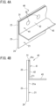
- FIGS. 4A and 4B are views illustrating a sealing member with the machine tool according to a second embodiment.
- FIG. 4A is a perspective view
- FIG. 4B is a side view.
- the same reference sign is assigned to a component in FIGS. 4A and 4B which is the same as that in the sealing member with the machine tool according to the first embodiment.
- a shape of a support member 41 is different from that in the first embodiment, and other configuration is similar to that of the sealing member with the machine tool according to the first embodiment.
- the support member 41 of the sealing member with the machine tool 40 includes a support portion 42 formed in a flat plate shape having a support surface 41a facing a front surface 21a of an elastic member 21, and a protection portion 43 formed in a flat plate shape vertically arranged at a side opposite to the support surface 41a of the support portion 42.
- the sealing member for machine tools 40 can protect the front surface 21a of the elastic member 21 from a chip when in use. Thus, it can be suppressed that the elastic member 21 is damaged due to collision of the chip when in use.
- a sealing member for machine tools 50 according to the third embodiment further includes a curve auxiliary member 51 at a side of a rear surface 21b of an elastic member 21 in addition to the configuration of the sealing member with the machine tool 40 according to the second embodiment.
- the body portion 52 of the curve auxiliary member 51 is joined to a part of a rear surface 21b of the elastic member 21 via an adhesive layer 38.
- auxiliary member 51 including the body portion 52 and the auxiliary portion 53
- a metal plate subjected to a bending process can be used.
- a bending angle ⁇ 2 of the auxiliary portion 53 against the body portion 52 is not especially limited, however the bending angle ⁇ 2 is normally set in a range between 15° and 60°.
- the sealing member with the machine tool 50 includes the curve auxiliary member 51, the sealing member with the machine tool tools 50 is suitable for mounting the sealing member with the machine tool 50 to the machine tool without making a mistake with respect to a mount direction of the sealing member for machine tools 50.
- a curve of the lip portion 23 of the elastic member 21 is supported by the curve auxiliary member 51.
- turn-up (reverse of the lip portion 23 of the elastic member 21) of the sealing member for machine tools is hardly generated when in use.
- the front surface 53a of the auxiliary portion 53 and the rear surface 21b of the elastic member 21 may not be necessarily contacted when in use.
- the support member and the elastic member, and the elastic member and the curve auxiliary member are joined via the adhesive layers.
- the support member and the elastic member, and the elastic member and the curve auxiliary member are not necessarily joined via the adhesive layers, and therefore they may merely physically adhere to each other. In this case, each of the support member, the elastic member and the curve auxiliary member can be replaced independently.
- the sealing member with the machine tool according to the third embodiment may include a support member formed in a flat plate shape similar to the support member of the sealing member for machine tools according to the first embodiment.
- a steel plate with an untreated surface a steel plate subjected to surface treatment such as zinc phosphate treatment, chromate treatment, and anti-rust resin treatment, an elastic metal plate such as phosphor copper and spring steel, and the like may be adopted.
- surface treatment by using primer may be applied to the support member.
- the elastic member is formed to slide on the sliding surface of the machine tool.
- the edge portion is contacted with the sliding surface of the machine tool.
- the sealing member for machine tools, and therefore examples of the material of the elastic member include NBR (nitrile butadiene rubber), urethane elastomer, fluororubber, silicon rubber, and EPDM (ethylene-propylene-diene rubber).
- NBR nonrile butadiene rubber
- urethane elastomer urethane elastomer
- fluororubber fluororubber
- silicon rubber silicon rubber
- EPDM ethylene-propylene-diene rubber
- the urethane elastomer is preferable because durability (wear resistance) is superior for keeping desirable properties for a long period of time.
- urethane elastomer examples include a product obtained by reaction with a polyol and a polyisocyanate, and a crosslinker as necessary.
- the polyol is not especially limited.
- Examples of the polyol include polyester polyol, polyether polyol, and polycaprolactone polyol.
- the number average molecular weight of the polyol is in a range between 1000 and 3000.
- the number average molecular weight is a measurement value in terms of polystyrene measured by the GPC (Gel Permeation Chromatography) measurement.
- Example of the polyester polyol includes polyester polyol obtained by reacting dicarboxylic acid and glycol in accordance with a routine procedure.
- dicarboxylic acid examples include aromatic dicarboxylic acid such as terephthalic acid, isophthalic acid, and 2,6-naphthalene dicarboxylic acid; aliphatic dicarboxylic acid such as adipic acid, azelaic acid, and sebacic acid; oxycarbonic acid such as oxybenzoic acid; and its ester-forming derivative.
- aromatic dicarboxylic acid such as terephthalic acid, isophthalic acid, and 2,6-naphthalene dicarboxylic acid
- aliphatic dicarboxylic acid such as adipic acid, azelaic acid, and sebacic acid
- oxycarbonic acid such as oxybenzoic acid
- ester-forming derivative examples of the dicarboxylic acids, the adipic acid is preferable because of its excellent wear resistance.
- the polyester polyol which is a reactant of dicarboxylic acid and glycol, has a linear structure, however branched polyester using a trivalent or more ester forming component may be adopted.
- polyether polyol examples include polyalkylene glycols such as polyethylene glycol, polypropylene glycol, polytetramethylene glycol, and copolymers thereof. Of these polyester polyols, the polytetramethylene glycol is preferable because of its excellent wear resistance.
- Example of the polycaprolactone polyol includes polycaprolactone polyol obtained by the ring opening addition of ⁇ -caprolactone using low molecular weight glycol as an initiator in the presence of a catalyst.
- dihydric alcohol such as ethylene glycol, propylene glycol, 1,3-butylene glycol, and neopentyl glycol
- trihydric alcohol such as trimethylene glycol, and glycerin is preferably used.
- the catalyst examples include an organotitanium-based compound such as tetrabutyl titanate, tetrapropyl titanate, and tetraethyl titanate; and a tin-based compound such as tin octylate, dibutyl tin oxide, dibutyl tin laurate, stannous chloride, and stannous bromide.
- organotitanium-based compound such as tetrabutyl titanate, tetrapropyl titanate, and tetraethyl titanate
- a tin-based compound such as tin octylate, dibutyl tin oxide, dibutyl tin laurate, stannous chloride, and stannous bromide.
- ring lactone such as trimethyl caprolactone and valerolactone may be mixed in part in addition to the ⁇ -caprolactone.
- the polyol may be used independently or two or more kinds of the polyols may be used together.
- the polyisocyanate is not especially limited, and therefore conventional known polyisocyanate may be used.
- Examples of the polyisocyanate include aliphatic isocyanate, alicyclic isocyanate, and aromatic isocyanate. Of these polyisocyanates, the aromatic isocyanate is preferable because of its excellent wear resistance.
- aliphatic isocyanate examples include 1,6-hexamethylene diisocyanate (HDI), 2,2,4-trimethylhexamethylene diisocyanate, and lysine diisocyanate. Further, examples of the aliphatic isocyanate also include modified products such as isocyanurate, biuret and adduct of hexamethylene diisocyanate or isophorone diisocyanate.
- HDI 1,6-hexamethylene diisocyanate
- 2,2,4-trimethylhexamethylene diisocyanate examples of the aliphatic isocyanate
- modified products such as isocyanurate, biuret and adduct of hexamethylene diisocyanate or isophorone diisocyanate.
- alicyclic isocyanate examples include isophorone diisocyanate (IPDI), 4,4'-dicyclohexylmethane diisocyanate, 1,4-cyclohexane diisocyanate, and norbornane diisocyanate (NBDI).
- IPDI isophorone diisocyanate
- NBDI norbornane diisocyanate
- aromatic isocyanate examples include 4,4'-diphenylmethane diisocyanate, polymethylene polyphenylene polyisocyanate, a compound of diphenylmethane diisocyanate and polymethylene polyphenylene polyisocyanate (hereinafter, these are also collectively referred to as MDI); tolylene diisocyanate (TDI), phenylene diisocyanate, 1,5-naphthalene diisocyanate, xylylene diisocyanate (XDI), carbodiimide-modified MDI, and urethane-modified MDI.
- MDI 4,4'-diphenylmethane diisocyanate
- polymethylene polyphenylene polyisocyanate a compound of diphenylmethane diisocyanate and polymethylene polyphenylene polyisocyanate
- MDI tolylene diisocyanate
- TDI tolylene diisocyanate
- XDI phenylene di
- the polyisocyanate is used independently or two or more kinds of the polyisocyanates may be used together.
- crosslinking agent examples include ethylene glycol, propylene glycol, butanediol, hexanediol, diethylene glycol, trimethylolpropane, glycerin, hydrazine, ethylenediamine, diethylenetriamine, 4,4'-diaminodiphenyl methane, 4,4'-diaminodicyclohexyl methane, N,N-bis (2-hydroxypropyl) aniline, and water.
- the butanediol and the trimethylolpropane are preferable because of their excellent oil resistance.
- the polyurethane elastomer can be produced by a known method using the materials described above. Specifically, for example, the polyurethane elastomer can be produced by adjusting an equivalent ratio of NCO/OH of each material is set to 0.9 to 1.1 and by reacting the materials in an appropriate organic solvent using a catalyst as needed, or by subjecting the materials to melting reaction without using a solvent.
- the polyurethane elastomer can be produced by a one shot method, a prepolymer method, or the like.
- a molding method of the elastic member is not especially limited. Examples of the molding method include atmospheric pressure cast molding, reduced pressure cast molding, centrifugal casting, continuous rotation molding, extrusion molding, injection molding, reactive injection molding (RIM), and spin coating.
- the molding method include atmospheric pressure cast molding, reduced pressure cast molding, centrifugal casting, continuous rotation molding, extrusion molding, injection molding, reactive injection molding (RIM), and spin coating.
- the centrifugal casting and the continuous rotation molding are preferable.
- a hardness of the elastic member is preferably set in a range between 55° and 90°.
- the hardness of the elastic member is less than 55°, the elastic member is deformed largely when sliding on the sliding surface of the machine tool, and therefore a chip or the like might not be prevented from entering firmly.
- the hardness of the elastic member is more than 90°, the elastic member is too hard and therefore the elastic member might be damaged when sliding.
- the hardness of the elastic member is more preferably set in a range between 60° and 75°.
- the JIS A hardness is a value measured by a spring type A hardness testing machine in accordance with JIS K 7312.
- An impact resilience of the elastic member is preferably set in a range between 10% and 50%.
- the impact resilience of the elastic member is more preferably set in a range between 20% and 40%.
- the impact resilience is a value measured in accordance with JIS K7312.
- the additive examples include powder formed of metal such as metal oxide such as cerium oxide, zinc oxide, iron oxide and silica, metal such as copper, nickel, iron and aluminum; short fiber formed of metal such as aluminum, stainless steel and iron, or short fiber formed of resin such as polyamide; and hollow particles such as glass balloon and fly ash balloon.
- metal oxide such as cerium oxide, zinc oxide, iron oxide and silica
- metal such as copper, nickel, iron and aluminum
- short fiber formed of metal such as aluminum, stainless steel and iron, or short fiber formed of resin such as polyamide
- hollow particles such as glass balloon and fly ash balloon.
- the adhesive layer that fixes the elastic member and the support member is not especially limited.
- the adhesive layer may be appropriately determined in consideration of materials of each member.
- a thickness of the adhesive layer is not especially limited, however the thickness is preferably set in a range between 50 ⁇ m and 500 ⁇ m.
- the sealing member for machine tools can be used as a seal member for protecting a working portion, a driving mechanism or the like in various machine tools such as a lathe and a machining center, from a chip, coolant or the like.
- the sealing member for machine tools can be used as a lip seal, a slide seal, a telescopic seal, a cover seal, or the like.
- the obtained urethane composition was entered into a centrifugal molding machine and the urethane composition was crosslinked in a condition of a molding die temperature of 150 °C and a crosslinking time of 60 minutes, and then a cylindrical cured product having a thickness of 1.6 mm was molded and released from the molding die. After that, one part of the cured product was cut to be developed into a plate shape, and then post-crosslinking was performed in a condition of 120 °C in a blower oven for 12 hours, so that a polyurethane raw sheet was obtained.
- the JIS A hardness of the urethane sheet was measured in accordance with JIS K 7312.
- the JIS A hardness was measured by laminating ten sheets of the urethane sheet having a thickness of 1.6 mm.
- the support member was fixed at a predetermined position on the front surface of the elastic member by using a double-sided tape having a width of 5 mm (No. 500 produced by Nitto Denko Corporation).
- the curve auxiliary member (not part of the present invention) was fixed on a predetermined position of the rear surface of the elastic member by using the double-sided tape. After that, a plurality of bolt holes was formed so that the sealing member for machine tools having the shape shown in FIG. 5 was produced.
- Working time 7.5 hours/day.
- Working rate approximately 50%.
- Cut material iron or aluminum (each of which includes casting).
- the edge portion 24 of the sealing member with the machine tool 50 was brought into contact with a PET sheet 60 such that an angle between the rear surface 21b of the elastic member 21 and a surface (mirror surface) 60a of the PET sheet 60 is to be 25°. Further, the edge portion 24 was pressed against the PET sheet 60 by applying a vertical load of 0.98 N to the sealing member for machine tools 50 downward in the vertical direction from an upper side of the curve auxiliary member 51.
- the reference sign 11 denotes the support member.
- Example 1 entering of chips into the gap between the fixed cover 103 and the moving cover 105 was observed, however the number of the chips is merely several number. On the other hand, in Comparative Example 1, entering of a large number of the chips into the gap between fixed cover 103 and the moving cover 105 was observed.
Landscapes
- Engineering & Computer Science (AREA)
- Mechanical Engineering (AREA)
- Sealing Devices (AREA)
- Sealing With Elastic Sealing Lips (AREA)
- Sealing Material Composition (AREA)
Claims (2)
- Dichtungsglied mit einer Werkzeugmaschine (10, 40), wobei das Dichtungsglied aus Folgendem besteht:einem Stützglied (11, 41),einem elastischen Glied (21), das in einer flachen Plattenform ausgebildet ist, wobei das elastische Glied (21) einen Randabschnitt (24) umfasst, der auf einer Gleitfläche (36) einer Werkzeugmaschine gleiten kann, undeine Klebeschicht (31),wobei:das Stützglied (11, 41) eine Stützfläche (11a, 41a) umfasst, die einem Teil einer Vorderfläche (21a) des elastischen Glieds (21) zugewandt ist,das Dichtungsglied so an der Werkzeugmaschine montiert ist, dass das elastische Glied (21) zwischen einem Montageabschnitt (35) der Werkzeugmaschine und der Stützfläche (11a) des Stützglieds (11) angeordnet ist,das elastische Glied (21) einen zwischen dem Montageabschnitt (35) und dem Stützglied (11, 41) angeordneten feststehenden Abschnitt (22) und einen Lippenabschnitt (23) umfasst, der nicht zwischen dem Montageabschnitt (35) und dem Stützglied (11, 41) angeordnet ist, wenn das Dichtungsglied für Werkzeugmaschinen (10) an der Werkzeugmaschine montiert ist, wobei der Lippenabschnitt (23) den Randabschnitt (24) aufweist und gekrümmt ausgestaltet ist,ein Material des elastischen Glieds (21) NBR (Acrylnitril-Butadien-Kautschuk), Urethan-Elastomer, Fluorkautschuk, Silikonkautschuk oder EPDM (Ethylen-Propylen-DienKautschuk) ist unddie Stützfläche (11a, 41a) des Stützglieds (11, 41) und die Vorderfläche (21a) des elastischen Glieds (21) über die Klebeschicht (31) verbunden sind.
- Dichtungsglied mit einer Werkzeugmaschine nach Anspruch 1, wobei das Stützglied (41) einen Schutzabschnitt (43) umfasst, der an einer der Stützfläche (41a) gegenüberliegenden Seite angeordnet ist.
Applications Claiming Priority (2)
| Application Number | Priority Date | Filing Date | Title |
|---|---|---|---|
| JP2015251378 | 2015-12-24 | ||
| PCT/JP2016/083090 WO2017110275A1 (ja) | 2015-12-24 | 2016-11-08 | 工作機械用シール部材 |
Publications (3)
| Publication Number | Publication Date |
|---|---|
| EP3395499A1 EP3395499A1 (de) | 2018-10-31 |
| EP3395499A4 EP3395499A4 (de) | 2019-07-24 |
| EP3395499B1 true EP3395499B1 (de) | 2024-07-03 |
Family
ID=59089292
Family Applications (1)
| Application Number | Title | Priority Date | Filing Date |
|---|---|---|---|
| EP16878173.0A Active EP3395499B1 (de) | 2015-12-24 | 2016-11-08 | Dichtungselement mit einer werkzeugmaschine |
Country Status (7)
| Country | Link |
|---|---|
| US (1) | US11260487B2 (de) |
| EP (1) | EP3395499B1 (de) |
| JP (1) | JP6177464B1 (de) |
| KR (1) | KR102156248B1 (de) |
| CN (1) | CN108472781B (de) |
| TW (1) | TWI694890B (de) |
| WO (1) | WO2017110275A1 (de) |
Families Citing this family (6)
| Publication number | Priority date | Publication date | Assignee | Title |
|---|---|---|---|---|
| JP6535709B2 (ja) * | 2017-08-08 | 2019-06-26 | バンドー化学株式会社 | 工作機械用シール部材 |
| KR102746225B1 (ko) * | 2019-02-14 | 2024-12-26 | 주식회사 디엔솔루션즈 | 공작기계의 와이퍼 장치 |
| JP2022084227A (ja) * | 2020-11-26 | 2022-06-07 | バンドー化学株式会社 | 寸法検査方法、寸法検査用スケール、及び工作機械用シール部材の製造方法 |
| CN114042981B (zh) * | 2021-12-01 | 2023-03-07 | 南京伟舜机电有限公司 | 一种数控铣床用精密型工作台 |
| TWI821078B (zh) * | 2022-12-20 | 2023-11-01 | 桓凱股份有限公司 | 自動化切削液混合系統 |
| US20250154877A1 (en) * | 2023-11-15 | 2025-05-15 | Rtx Corporation | Slider seal of gas turbine engine |
Family Cites Families (26)
| Publication number | Priority date | Publication date | Assignee | Title |
|---|---|---|---|---|
| US3771799A (en) * | 1971-08-20 | 1973-11-13 | Mather Co | Multi-element fluctuating pressure seal |
| US4522411A (en) * | 1984-10-01 | 1985-06-11 | Chicago Rawhide Mfg. Co. | Fluid seals with self-venting auxiliary lips |
| JPH0248207Y2 (de) * | 1984-11-02 | 1990-12-18 | ||
| JPS62258267A (ja) * | 1986-05-02 | 1987-11-10 | Taiho Kogyo Co Ltd | シ−ル装置 |
| JPS6430975A (en) * | 1987-07-24 | 1989-02-01 | Taiho Kogyo Co Ltd | Lip seal device |
| JPH081257B2 (ja) * | 1990-08-23 | 1996-01-10 | 株式会社小松製作所 | オイルシール |
| US6182975B1 (en) * | 1993-06-04 | 2001-02-06 | Nok Corporation | Sealing device having an annular space between sealing lips |
| JP3212448B2 (ja) * | 1994-06-28 | 2001-09-25 | ニッタ株式会社 | 工業用スクレーパ |
| JP2805134B2 (ja) * | 1994-09-12 | 1998-09-30 | オークマ株式会社 | ワイパー |
| JP2001310238A (ja) * | 2000-04-28 | 2001-11-06 | Nok Corp | 工作機械用スクレーパ |
| JP2001317635A (ja) * | 2000-05-02 | 2001-11-16 | Toyota Industries Corp | リップ型シール |
| JP4648514B2 (ja) * | 2000-05-02 | 2011-03-09 | イーグル工業株式会社 | リップ型シール |
| CN2448516Y (zh) * | 2000-10-26 | 2001-09-19 | 陈佩芳 | 防尘盖刮板结构 |
| JP4865966B2 (ja) * | 2001-08-17 | 2012-02-01 | バンドー化学株式会社 | 工作機械用のワイパー部材 |
| JP4102610B2 (ja) * | 2002-07-26 | 2008-06-18 | オークマ株式会社 | ワイパ及びその製造方法 |
| DE10353306A1 (de) * | 2002-11-11 | 2004-05-27 | Kaco Gmbh + Co. Kg | Dichtring |
| JP2005246490A (ja) * | 2004-03-01 | 2005-09-15 | Hatakeyama Seisakusho:Kk | 工作機械等の可動部における保護カバー |
| JP2007083344A (ja) | 2005-09-22 | 2007-04-05 | Nitta Ind Corp | 工業用ワイパー |
| JP3863556B1 (ja) | 2006-04-25 | 2006-12-27 | ニッタ株式会社 | 工作機械用ワイパー |
| JP5043481B2 (ja) * | 2007-03-15 | 2012-10-10 | オークマ株式会社 | ワイパー |
| DE102011077015A1 (de) * | 2011-06-06 | 2012-12-06 | Elringklinger Ag | Radialwellendichtung |
| US9016696B2 (en) * | 2011-12-22 | 2015-04-28 | Upsite Technologies, Inc. | Air seal for server rack |
| CN102975079A (zh) * | 2012-11-20 | 2013-03-20 | 大连天润新能源科技有限公司 | 一种刮板式导轨防护装置 |
| CN203611063U (zh) * | 2013-09-23 | 2014-05-28 | 上海三一精机有限公司 | 一种复合机床内防护结构及机床 |
| WO2015119030A1 (ja) * | 2014-02-06 | 2015-08-13 | バンドー化学株式会社 | 工作機械用シール部材 |
| CN104174197B (zh) * | 2014-07-19 | 2016-11-23 | 芜湖恒坤汽车部件有限公司 | 一种切屑过滤收集装置 |
-
2016
- 2016-11-08 EP EP16878173.0A patent/EP3395499B1/de active Active
- 2016-11-08 CN CN201680075797.9A patent/CN108472781B/zh active Active
- 2016-11-08 JP JP2016567942A patent/JP6177464B1/ja active Active
- 2016-11-08 KR KR1020187015485A patent/KR102156248B1/ko active Active
- 2016-11-08 US US16/065,574 patent/US11260487B2/en not_active Expired - Fee Related
- 2016-11-08 WO PCT/JP2016/083090 patent/WO2017110275A1/ja not_active Ceased
- 2016-11-17 TW TW105137540A patent/TWI694890B/zh active
Also Published As
| Publication number | Publication date |
|---|---|
| KR102156248B1 (ko) | 2020-09-15 |
| TW201735770A (zh) | 2017-10-16 |
| CN108472781A (zh) | 2018-08-31 |
| EP3395499A1 (de) | 2018-10-31 |
| US20200262017A1 (en) | 2020-08-20 |
| US11260487B2 (en) | 2022-03-01 |
| CN108472781B (zh) | 2021-01-12 |
| EP3395499A4 (de) | 2019-07-24 |
| KR20180071363A (ko) | 2018-06-27 |
| WO2017110275A1 (ja) | 2017-06-29 |
| TWI694890B (zh) | 2020-06-01 |
| JP6177464B1 (ja) | 2017-08-09 |
| JPWO2017110275A1 (ja) | 2017-12-21 |
Similar Documents
| Publication | Publication Date | Title |
|---|---|---|
| EP3395499B1 (de) | Dichtungselement mit einer werkzeugmaschine | |
| US8594553B2 (en) | Cleaning blade for electrophotographic apparatus, and method for producing the same | |
| EP3103584B1 (de) | Dichtungselement für maschinenwerkzeuge | |
| TWI763899B (zh) | 工作機械用密封部材 | |
| CN108472782B (zh) | 工作机械用密封部材 | |
| JP6822779B2 (ja) | 工作機械用シール部材 | |
| CN104704429B (zh) | 电子照相装置用刮板及其制造方法 | |
| JP2023013080A (ja) | 工作機械用シール部材 | |
| TWI719071B (zh) | 工作機械用密封構件 |
Legal Events
| Date | Code | Title | Description |
|---|---|---|---|
| STAA | Information on the status of an ep patent application or granted ep patent |
Free format text: STATUS: THE INTERNATIONAL PUBLICATION HAS BEEN MADE |
|
| PUAI | Public reference made under article 153(3) epc to a published international application that has entered the european phase |
Free format text: ORIGINAL CODE: 0009012 |
|
| STAA | Information on the status of an ep patent application or granted ep patent |
Free format text: STATUS: REQUEST FOR EXAMINATION WAS MADE |
|
| 17P | Request for examination filed |
Effective date: 20180711 |
|
| AK | Designated contracting states |
Kind code of ref document: A1 Designated state(s): AL AT BE BG CH CY CZ DE DK EE ES FI FR GB GR HR HU IE IS IT LI LT LU LV MC MK MT NL NO PL PT RO RS SE SI SK SM TR |
|
| AX | Request for extension of the european patent |
Extension state: BA ME |
|
| DAV | Request for validation of the european patent (deleted) | ||
| DAX | Request for extension of the european patent (deleted) | ||
| A4 | Supplementary search report drawn up and despatched |
Effective date: 20190624 |
|
| RIC1 | Information provided on ipc code assigned before grant |
Ipc: B23Q 11/08 20060101AFI20190617BHEP |
|
| STAA | Information on the status of an ep patent application or granted ep patent |
Free format text: STATUS: EXAMINATION IS IN PROGRESS |
|
| 17Q | First examination report despatched |
Effective date: 20201203 |
|
| GRAP | Despatch of communication of intention to grant a patent |
Free format text: ORIGINAL CODE: EPIDOSNIGR1 |
|
| STAA | Information on the status of an ep patent application or granted ep patent |
Free format text: STATUS: GRANT OF PATENT IS INTENDED |
|
| INTG | Intention to grant announced |
Effective date: 20240327 |
|
| RIN1 | Information on inventor provided before grant (corrected) |
Inventor name: KANNAKA, MASATOSHI Inventor name: IWASAKI, NARIAKI Inventor name: ABE, YUKI |
|
| GRAS | Grant fee paid |
Free format text: ORIGINAL CODE: EPIDOSNIGR3 |
|
| GRAA | (expected) grant |
Free format text: ORIGINAL CODE: 0009210 |
|
| STAA | Information on the status of an ep patent application or granted ep patent |
Free format text: STATUS: THE PATENT HAS BEEN GRANTED |
|
| AK | Designated contracting states |
Kind code of ref document: B1 Designated state(s): AL AT BE BG CH CY CZ DE DK EE ES FI FR GB GR HR HU IE IS IT LI LT LU LV MC MK MT NL NO PL PT RO RS SE SI SK SM TR |
|
| REG | Reference to a national code |
Ref country code: CH Ref legal event code: EP |
|
| REG | Reference to a national code |
Ref country code: DE Ref legal event code: R096 Ref document number: 602016088269 Country of ref document: DE |
|
| REG | Reference to a national code |
Ref country code: LT Ref legal event code: MG9D |
|
| REG | Reference to a national code |
Ref country code: NL Ref legal event code: MP Effective date: 20240703 |
|
| PG25 | Lapsed in a contracting state [announced via postgrant information from national office to epo] |
Ref country code: PT Free format text: LAPSE BECAUSE OF FAILURE TO SUBMIT A TRANSLATION OF THE DESCRIPTION OR TO PAY THE FEE WITHIN THE PRESCRIBED TIME-LIMIT Effective date: 20241104 |
|
| REG | Reference to a national code |
Ref country code: AT Ref legal event code: MK05 Ref document number: 1699355 Country of ref document: AT Kind code of ref document: T Effective date: 20240703 |
|
| PG25 | Lapsed in a contracting state [announced via postgrant information from national office to epo] |
Ref country code: NL Free format text: LAPSE BECAUSE OF FAILURE TO SUBMIT A TRANSLATION OF THE DESCRIPTION OR TO PAY THE FEE WITHIN THE PRESCRIBED TIME-LIMIT Effective date: 20240703 |
|
| PG25 | Lapsed in a contracting state [announced via postgrant information from national office to epo] |
Ref country code: PT Free format text: LAPSE BECAUSE OF FAILURE TO SUBMIT A TRANSLATION OF THE DESCRIPTION OR TO PAY THE FEE WITHIN THE PRESCRIBED TIME-LIMIT Effective date: 20241104 Ref country code: NL Free format text: LAPSE BECAUSE OF FAILURE TO SUBMIT A TRANSLATION OF THE DESCRIPTION OR TO PAY THE FEE WITHIN THE PRESCRIBED TIME-LIMIT Effective date: 20240703 |
|
| PG25 | Lapsed in a contracting state [announced via postgrant information from national office to epo] |
Ref country code: NO Free format text: LAPSE BECAUSE OF FAILURE TO SUBMIT A TRANSLATION OF THE DESCRIPTION OR TO PAY THE FEE WITHIN THE PRESCRIBED TIME-LIMIT Effective date: 20241003 |
|
| PG25 | Lapsed in a contracting state [announced via postgrant information from national office to epo] |
Ref country code: GR Free format text: LAPSE BECAUSE OF FAILURE TO SUBMIT A TRANSLATION OF THE DESCRIPTION OR TO PAY THE FEE WITHIN THE PRESCRIBED TIME-LIMIT Effective date: 20241004 Ref country code: FI Free format text: LAPSE BECAUSE OF FAILURE TO SUBMIT A TRANSLATION OF THE DESCRIPTION OR TO PAY THE FEE WITHIN THE PRESCRIBED TIME-LIMIT Effective date: 20240703 Ref country code: PL Free format text: LAPSE BECAUSE OF FAILURE TO SUBMIT A TRANSLATION OF THE DESCRIPTION OR TO PAY THE FEE WITHIN THE PRESCRIBED TIME-LIMIT Effective date: 20240703 |
|
| PG25 | Lapsed in a contracting state [announced via postgrant information from national office to epo] |
Ref country code: BG Free format text: LAPSE BECAUSE OF FAILURE TO SUBMIT A TRANSLATION OF THE DESCRIPTION OR TO PAY THE FEE WITHIN THE PRESCRIBED TIME-LIMIT Effective date: 20240703 |
|
| PG25 | Lapsed in a contracting state [announced via postgrant information from national office to epo] |
Ref country code: LV Free format text: LAPSE BECAUSE OF FAILURE TO SUBMIT A TRANSLATION OF THE DESCRIPTION OR TO PAY THE FEE WITHIN THE PRESCRIBED TIME-LIMIT Effective date: 20240703 |
|
| PG25 | Lapsed in a contracting state [announced via postgrant information from national office to epo] |
Ref country code: IS Free format text: LAPSE BECAUSE OF FAILURE TO SUBMIT A TRANSLATION OF THE DESCRIPTION OR TO PAY THE FEE WITHIN THE PRESCRIBED TIME-LIMIT Effective date: 20241103 Ref country code: AT Free format text: LAPSE BECAUSE OF FAILURE TO SUBMIT A TRANSLATION OF THE DESCRIPTION OR TO PAY THE FEE WITHIN THE PRESCRIBED TIME-LIMIT Effective date: 20240703 |
|
| PG25 | Lapsed in a contracting state [announced via postgrant information from national office to epo] |
Ref country code: CZ Free format text: LAPSE BECAUSE OF FAILURE TO SUBMIT A TRANSLATION OF THE DESCRIPTION OR TO PAY THE FEE WITHIN THE PRESCRIBED TIME-LIMIT Effective date: 20240703 Ref country code: HR Free format text: LAPSE BECAUSE OF FAILURE TO SUBMIT A TRANSLATION OF THE DESCRIPTION OR TO PAY THE FEE WITHIN THE PRESCRIBED TIME-LIMIT Effective date: 20240703 |
|
| PG25 | Lapsed in a contracting state [announced via postgrant information from national office to epo] |
Ref country code: RS Free format text: LAPSE BECAUSE OF FAILURE TO SUBMIT A TRANSLATION OF THE DESCRIPTION OR TO PAY THE FEE WITHIN THE PRESCRIBED TIME-LIMIT Effective date: 20241003 Ref country code: ES Free format text: LAPSE BECAUSE OF FAILURE TO SUBMIT A TRANSLATION OF THE DESCRIPTION OR TO PAY THE FEE WITHIN THE PRESCRIBED TIME-LIMIT Effective date: 20240703 |
|
| PG25 | Lapsed in a contracting state [announced via postgrant information from national office to epo] |
Ref country code: RS Free format text: LAPSE BECAUSE OF FAILURE TO SUBMIT A TRANSLATION OF THE DESCRIPTION OR TO PAY THE FEE WITHIN THE PRESCRIBED TIME-LIMIT Effective date: 20241003 Ref country code: PL Free format text: LAPSE BECAUSE OF FAILURE TO SUBMIT A TRANSLATION OF THE DESCRIPTION OR TO PAY THE FEE WITHIN THE PRESCRIBED TIME-LIMIT Effective date: 20240703 Ref country code: NO Free format text: LAPSE BECAUSE OF FAILURE TO SUBMIT A TRANSLATION OF THE DESCRIPTION OR TO PAY THE FEE WITHIN THE PRESCRIBED TIME-LIMIT Effective date: 20241003 Ref country code: LV Free format text: LAPSE BECAUSE OF FAILURE TO SUBMIT A TRANSLATION OF THE DESCRIPTION OR TO PAY THE FEE WITHIN THE PRESCRIBED TIME-LIMIT Effective date: 20240703 Ref country code: IS Free format text: LAPSE BECAUSE OF FAILURE TO SUBMIT A TRANSLATION OF THE DESCRIPTION OR TO PAY THE FEE WITHIN THE PRESCRIBED TIME-LIMIT Effective date: 20241103 Ref country code: HR Free format text: LAPSE BECAUSE OF FAILURE TO SUBMIT A TRANSLATION OF THE DESCRIPTION OR TO PAY THE FEE WITHIN THE PRESCRIBED TIME-LIMIT Effective date: 20240703 Ref country code: GR Free format text: LAPSE BECAUSE OF FAILURE TO SUBMIT A TRANSLATION OF THE DESCRIPTION OR TO PAY THE FEE WITHIN THE PRESCRIBED TIME-LIMIT Effective date: 20241004 Ref country code: FI Free format text: LAPSE BECAUSE OF FAILURE TO SUBMIT A TRANSLATION OF THE DESCRIPTION OR TO PAY THE FEE WITHIN THE PRESCRIBED TIME-LIMIT Effective date: 20240703 Ref country code: ES Free format text: LAPSE BECAUSE OF FAILURE TO SUBMIT A TRANSLATION OF THE DESCRIPTION OR TO PAY THE FEE WITHIN THE PRESCRIBED TIME-LIMIT Effective date: 20240703 Ref country code: CZ Free format text: LAPSE BECAUSE OF FAILURE TO SUBMIT A TRANSLATION OF THE DESCRIPTION OR TO PAY THE FEE WITHIN THE PRESCRIBED TIME-LIMIT Effective date: 20240703 Ref country code: BG Free format text: LAPSE BECAUSE OF FAILURE TO SUBMIT A TRANSLATION OF THE DESCRIPTION OR TO PAY THE FEE WITHIN THE PRESCRIBED TIME-LIMIT Effective date: 20240703 Ref country code: AT Free format text: LAPSE BECAUSE OF FAILURE TO SUBMIT A TRANSLATION OF THE DESCRIPTION OR TO PAY THE FEE WITHIN THE PRESCRIBED TIME-LIMIT Effective date: 20240703 |
|
| REG | Reference to a national code |
Ref country code: DE Ref legal event code: R097 Ref document number: 602016088269 Country of ref document: DE |
|
| PG25 | Lapsed in a contracting state [announced via postgrant information from national office to epo] |
Ref country code: RO Free format text: LAPSE BECAUSE OF FAILURE TO SUBMIT A TRANSLATION OF THE DESCRIPTION OR TO PAY THE FEE WITHIN THE PRESCRIBED TIME-LIMIT Effective date: 20240703 Ref country code: DK Free format text: LAPSE BECAUSE OF FAILURE TO SUBMIT A TRANSLATION OF THE DESCRIPTION OR TO PAY THE FEE WITHIN THE PRESCRIBED TIME-LIMIT Effective date: 20240703 Ref country code: SM Free format text: LAPSE BECAUSE OF FAILURE TO SUBMIT A TRANSLATION OF THE DESCRIPTION OR TO PAY THE FEE WITHIN THE PRESCRIBED TIME-LIMIT Effective date: 20240703 |
|
| PG25 | Lapsed in a contracting state [announced via postgrant information from national office to epo] |
Ref country code: EE Free format text: LAPSE BECAUSE OF FAILURE TO SUBMIT A TRANSLATION OF THE DESCRIPTION OR TO PAY THE FEE WITHIN THE PRESCRIBED TIME-LIMIT Effective date: 20240703 |
|
| PG25 | Lapsed in a contracting state [announced via postgrant information from national office to epo] |
Ref country code: IT Free format text: LAPSE BECAUSE OF FAILURE TO SUBMIT A TRANSLATION OF THE DESCRIPTION OR TO PAY THE FEE WITHIN THE PRESCRIBED TIME-LIMIT Effective date: 20240703 Ref country code: SK Free format text: LAPSE BECAUSE OF FAILURE TO SUBMIT A TRANSLATION OF THE DESCRIPTION OR TO PAY THE FEE WITHIN THE PRESCRIBED TIME-LIMIT Effective date: 20240703 |
|
| PLBE | No opposition filed within time limit |
Free format text: ORIGINAL CODE: 0009261 |
|
| STAA | Information on the status of an ep patent application or granted ep patent |
Free format text: STATUS: NO OPPOSITION FILED WITHIN TIME LIMIT |
|
| 26N | No opposition filed |
Effective date: 20250404 |
|
| REG | Reference to a national code |
Ref country code: CH Ref legal event code: PL |
|
| PG25 | Lapsed in a contracting state [announced via postgrant information from national office to epo] |
Ref country code: MC Free format text: LAPSE BECAUSE OF FAILURE TO SUBMIT A TRANSLATION OF THE DESCRIPTION OR TO PAY THE FEE WITHIN THE PRESCRIBED TIME-LIMIT Effective date: 20240703 |
|
| PG25 | Lapsed in a contracting state [announced via postgrant information from national office to epo] |
Ref country code: LU Free format text: LAPSE BECAUSE OF NON-PAYMENT OF DUE FEES Effective date: 20241108 |
|
| REG | Reference to a national code |
Ref country code: CH Ref legal event code: PL |
|
| GBPC | Gb: european patent ceased through non-payment of renewal fee |
Effective date: 20241108 |
|
| PG25 | Lapsed in a contracting state [announced via postgrant information from national office to epo] |
Ref country code: CH Free format text: LAPSE BECAUSE OF NON-PAYMENT OF DUE FEES Effective date: 20241130 |
|
| REG | Reference to a national code |
Ref country code: BE Ref legal event code: MM Effective date: 20241130 |
|
| PG25 | Lapsed in a contracting state [announced via postgrant information from national office to epo] |
Ref country code: SE Free format text: LAPSE BECAUSE OF FAILURE TO SUBMIT A TRANSLATION OF THE DESCRIPTION OR TO PAY THE FEE WITHIN THE PRESCRIBED TIME-LIMIT Effective date: 20240703 |
|
| PG25 | Lapsed in a contracting state [announced via postgrant information from national office to epo] |
Ref country code: BE Free format text: LAPSE BECAUSE OF NON-PAYMENT OF DUE FEES Effective date: 20241130 Ref country code: GB Free format text: LAPSE BECAUSE OF NON-PAYMENT OF DUE FEES Effective date: 20241108 |
|
| PG25 | Lapsed in a contracting state [announced via postgrant information from national office to epo] |
Ref country code: FR Free format text: LAPSE BECAUSE OF NON-PAYMENT OF DUE FEES Effective date: 20241130 |
|
| PG25 | Lapsed in a contracting state [announced via postgrant information from national office to epo] |
Ref country code: IE Free format text: LAPSE BECAUSE OF NON-PAYMENT OF DUE FEES Effective date: 20241108 |
|
| PGFP | Annual fee paid to national office [announced via postgrant information from national office to epo] |
Ref country code: DE Payment date: 20250930 Year of fee payment: 10 |
|
| PG25 | Lapsed in a contracting state [announced via postgrant information from national office to epo] |
Ref country code: HU Free format text: LAPSE BECAUSE OF FAILURE TO SUBMIT A TRANSLATION OF THE DESCRIPTION OR TO PAY THE FEE WITHIN THE PRESCRIBED TIME-LIMIT; INVALID AB INITIO Effective date: 20161108 |
|
| PG25 | Lapsed in a contracting state [announced via postgrant information from national office to epo] |
Ref country code: CY Free format text: LAPSE BECAUSE OF FAILURE TO SUBMIT A TRANSLATION OF THE DESCRIPTION OR TO PAY THE FEE WITHIN THE PRESCRIBED TIME-LIMIT; INVALID AB INITIO Effective date: 20161108 |