EP3390686B1 - Procede de depot d'un revetement par dli-mocvd avec recyclage direct du compose precurseur. - Google Patents
Procede de depot d'un revetement par dli-mocvd avec recyclage direct du compose precurseur. Download PDFInfo
- Publication number
- EP3390686B1 EP3390686B1 EP16831495.3A EP16831495A EP3390686B1 EP 3390686 B1 EP3390686 B1 EP 3390686B1 EP 16831495 A EP16831495 A EP 16831495A EP 3390686 B1 EP3390686 B1 EP 3390686B1
- Authority
- EP
- European Patent Office
- Prior art keywords
- precursor
- deposition
- transition metal
- process according
- reactor
- Prior art date
- Legal status (The legal status is an assumption and is not a legal conclusion. Google has not performed a legal analysis and makes no representation as to the accuracy of the status listed.)
- Active
Links
- 239000002243 precursor Substances 0.000 title claims description 147
- 238000000034 method Methods 0.000 title claims description 91
- 238000000151 deposition Methods 0.000 title claims description 71
- 238000000576 coating method Methods 0.000 title description 41
- 150000001875 compounds Chemical class 0.000 title description 33
- 238000004064 recycling Methods 0.000 title description 19
- 239000011248 coating agent Substances 0.000 title description 17
- 239000000243 solution Substances 0.000 claims description 87
- 230000008569 process Effects 0.000 claims description 65
- 230000008021 deposition Effects 0.000 claims description 64
- 229910052723 transition metal Inorganic materials 0.000 claims description 51
- 150000003624 transition metals Chemical class 0.000 claims description 51
- 239000002904 solvent Substances 0.000 claims description 48
- 239000000758 substrate Substances 0.000 claims description 37
- 229910052804 chromium Inorganic materials 0.000 claims description 35
- UHOVQNZJYSORNB-UHFFFAOYSA-N Benzene Chemical group C1=CC=CC=C1 UHOVQNZJYSORNB-UHFFFAOYSA-N 0.000 claims description 32
- 229910045601 alloy Inorganic materials 0.000 claims description 32
- 239000000956 alloy Substances 0.000 claims description 32
- 238000005137 deposition process Methods 0.000 claims description 31
- 238000002488 metal-organic chemical vapour deposition Methods 0.000 claims description 29
- 150000004945 aromatic hydrocarbons Chemical class 0.000 claims description 26
- 238000000354 decomposition reaction Methods 0.000 claims description 22
- 239000006227 byproduct Substances 0.000 claims description 21
- 239000011253 protective coating Substances 0.000 claims description 21
- 229910052799 carbon Inorganic materials 0.000 claims description 19
- 238000002347 injection Methods 0.000 claims description 19
- 239000007924 injection Substances 0.000 claims description 19
- 239000010413 mother solution Substances 0.000 claims description 18
- 239000000463 material Substances 0.000 claims description 17
- 125000003118 aryl group Chemical group 0.000 claims description 16
- 239000007788 liquid Substances 0.000 claims description 16
- 229910052786 argon Inorganic materials 0.000 claims description 14
- 238000005229 chemical vapour deposition Methods 0.000 claims description 14
- 230000001681 protective effect Effects 0.000 claims description 14
- 239000011241 protective layer Substances 0.000 claims description 14
- 238000007254 oxidation reaction Methods 0.000 claims description 12
- 239000000654 additive Substances 0.000 claims description 11
- 230000000996 additive effect Effects 0.000 claims description 11
- 238000009833 condensation Methods 0.000 claims description 11
- 230000005494 condensation Effects 0.000 claims description 11
- 229930195733 hydrocarbon Natural products 0.000 claims description 11
- 150000002430 hydrocarbons Chemical class 0.000 claims description 11
- 230000003647 oxidation Effects 0.000 claims description 11
- 150000002902 organometallic compounds Chemical class 0.000 claims description 10
- 229910052720 vanadium Inorganic materials 0.000 claims description 10
- 238000010348 incorporation Methods 0.000 claims description 9
- 239000003112 inhibitor Substances 0.000 claims description 9
- 230000008016 vaporization Effects 0.000 claims description 9
- 239000010410 layer Substances 0.000 claims description 7
- 125000004430 oxygen atom Chemical group O* 0.000 claims description 7
- -1 monocyclic aromatic hydrocarbon Chemical class 0.000 claims description 6
- 229910052758 niobium Inorganic materials 0.000 claims description 6
- 239000004215 Carbon black (E152) Substances 0.000 claims description 5
- 238000009835 boiling Methods 0.000 claims description 5
- 125000001449 isopropyl group Chemical group [H]C([H])([H])C([H])(*)C([H])([H])[H] 0.000 claims description 5
- 229910052748 manganese Inorganic materials 0.000 claims description 5
- 229910052750 molybdenum Inorganic materials 0.000 claims description 5
- 229910052735 hafnium Inorganic materials 0.000 claims description 4
- 229910003470 tongbaite Inorganic materials 0.000 claims description 4
- 229910052721 tungsten Inorganic materials 0.000 claims description 4
- 125000001495 ethyl group Chemical group [H]C([H])([H])C([H])([H])* 0.000 claims description 3
- 125000002496 methyl group Chemical group [H]C([H])([H])* 0.000 claims description 3
- 125000000217 alkyl group Chemical group 0.000 claims description 2
- 125000001997 phenyl group Chemical group [H]C1=C([H])C([H])=C(*)C([H])=C1[H] 0.000 claims description 2
- 229910016807 Mn3C Inorganic materials 0.000 claims 1
- 229910003178 Mo2C Inorganic materials 0.000 claims 1
- 239000011651 chromium Substances 0.000 description 76
- 229910052751 metal Inorganic materials 0.000 description 45
- 239000002184 metal Substances 0.000 description 41
- 208000037998 chronic venous disease Diseases 0.000 description 37
- YXFVVABEGXRONW-UHFFFAOYSA-N Toluene Chemical compound CC1=CC=CC=C1 YXFVVABEGXRONW-UHFFFAOYSA-N 0.000 description 36
- VYZAMTAEIAYCRO-UHFFFAOYSA-N Chromium Chemical compound [Cr] VYZAMTAEIAYCRO-UHFFFAOYSA-N 0.000 description 34
- 239000011550 stock solution Substances 0.000 description 33
- 238000006243 chemical reaction Methods 0.000 description 25
- 239000000203 mixture Substances 0.000 description 23
- 239000007789 gas Substances 0.000 description 19
- 239000003446 ligand Substances 0.000 description 16
- OKTJSMMVPCPJKN-UHFFFAOYSA-N Carbon Chemical compound [C] OKTJSMMVPCPJKN-UHFFFAOYSA-N 0.000 description 15
- 241000894007 species Species 0.000 description 13
- 239000003153 chemical reaction reagent Substances 0.000 description 12
- 239000000126 substance Substances 0.000 description 12
- 125000002524 organometallic group Chemical group 0.000 description 11
- 239000010408 film Substances 0.000 description 10
- 150000001247 metal acetylides Chemical class 0.000 description 9
- 239000012159 carrier gas Substances 0.000 description 8
- 230000007613 environmental effect Effects 0.000 description 8
- 238000002835 absorbance Methods 0.000 description 7
- 230000008901 benefit Effects 0.000 description 7
- 239000000919 ceramic Substances 0.000 description 7
- 238000005516 engineering process Methods 0.000 description 7
- 238000004519 manufacturing process Methods 0.000 description 7
- 230000007246 mechanism Effects 0.000 description 7
- 238000011282 treatment Methods 0.000 description 7
- 238000009834 vaporization Methods 0.000 description 7
- IJGRMHOSHXDMSA-UHFFFAOYSA-N Atomic nitrogen Chemical compound N#N IJGRMHOSHXDMSA-UHFFFAOYSA-N 0.000 description 6
- 238000001704 evaporation Methods 0.000 description 6
- 230000008020 evaporation Effects 0.000 description 6
- 238000005259 measurement Methods 0.000 description 6
- 239000012071 phase Substances 0.000 description 6
- RMVRSNDYEFQCLF-UHFFFAOYSA-N thiophenol Chemical group SC1=CC=CC=C1 RMVRSNDYEFQCLF-UHFFFAOYSA-N 0.000 description 6
- 229910000599 Cr alloy Inorganic materials 0.000 description 5
- 239000010955 niobium Substances 0.000 description 5
- 238000001228 spectrum Methods 0.000 description 5
- XKRFYHLGVUSROY-UHFFFAOYSA-N Argon Chemical compound [Ar] XKRFYHLGVUSROY-UHFFFAOYSA-N 0.000 description 4
- YNQLUTRBYVCPMQ-UHFFFAOYSA-N Ethylbenzene Chemical compound CCC1=CC=CC=C1 YNQLUTRBYVCPMQ-UHFFFAOYSA-N 0.000 description 4
- 229910000756 V alloy Inorganic materials 0.000 description 4
- UFGZSIPAQKLCGR-UHFFFAOYSA-N chromium carbide Chemical compound [Cr]#C[Cr]C#[Cr] UFGZSIPAQKLCGR-UHFFFAOYSA-N 0.000 description 4
- 238000005260 corrosion Methods 0.000 description 4
- 230000007797 corrosion Effects 0.000 description 4
- 238000002474 experimental method Methods 0.000 description 4
- 150000004820 halides Chemical class 0.000 description 4
- 239000012535 impurity Substances 0.000 description 4
- 239000000523 sample Substances 0.000 description 4
- 238000002798 spectrophotometry method Methods 0.000 description 4
- 238000003860 storage Methods 0.000 description 4
- LEONUFNNVUYDNQ-UHFFFAOYSA-N vanadium atom Chemical compound [V] LEONUFNNVUYDNQ-UHFFFAOYSA-N 0.000 description 4
- 229910003902 SiCl 4 Inorganic materials 0.000 description 3
- XUIMIQQOPSSXEZ-UHFFFAOYSA-N Silicon Chemical compound [Si] XUIMIQQOPSSXEZ-UHFFFAOYSA-N 0.000 description 3
- NINIDFKCEFEMDL-UHFFFAOYSA-N Sulfur Chemical compound [S] NINIDFKCEFEMDL-UHFFFAOYSA-N 0.000 description 3
- 230000015572 biosynthetic process Effects 0.000 description 3
- 238000005234 chemical deposition Methods 0.000 description 3
- SLLGVCUQYRMELA-UHFFFAOYSA-N chlorosilicon Chemical compound Cl[Si] SLLGVCUQYRMELA-UHFFFAOYSA-N 0.000 description 3
- 238000004453 electron probe microanalysis Methods 0.000 description 3
- 238000007373 indentation Methods 0.000 description 3
- 150000004767 nitrides Chemical class 0.000 description 3
- 229910052757 nitrogen Inorganic materials 0.000 description 3
- 229910021420 polycrystalline silicon Inorganic materials 0.000 description 3
- 239000000843 powder Substances 0.000 description 3
- 239000000047 product Substances 0.000 description 3
- 238000010926 purge Methods 0.000 description 3
- 239000010453 quartz Substances 0.000 description 3
- 238000011084 recovery Methods 0.000 description 3
- 229910052710 silicon Inorganic materials 0.000 description 3
- 239000010703 silicon Substances 0.000 description 3
- VYPSYNLAJGMNEJ-UHFFFAOYSA-N silicon dioxide Inorganic materials O=[Si]=O VYPSYNLAJGMNEJ-UHFFFAOYSA-N 0.000 description 3
- 239000002356 single layer Substances 0.000 description 3
- 229910052717 sulfur Inorganic materials 0.000 description 3
- 239000011593 sulfur Substances 0.000 description 3
- 238000002834 transmittance Methods 0.000 description 3
- LFQSCWFLJHTTHZ-UHFFFAOYSA-N Ethanol Chemical compound CCO LFQSCWFLJHTTHZ-UHFFFAOYSA-N 0.000 description 2
- 229910001257 Nb alloy Inorganic materials 0.000 description 2
- 238000010521 absorption reaction Methods 0.000 description 2
- 150000001335 aliphatic alkanes Chemical class 0.000 description 2
- 150000001338 aliphatic hydrocarbons Chemical class 0.000 description 2
- 150000001336 alkenes Chemical class 0.000 description 2
- 238000004458 analytical method Methods 0.000 description 2
- QVGXLLKOCUKJST-UHFFFAOYSA-N atomic oxygen Chemical compound [O] QVGXLLKOCUKJST-UHFFFAOYSA-N 0.000 description 2
- 150000001555 benzenes Chemical group 0.000 description 2
- 230000008033 biological extinction Effects 0.000 description 2
- 230000000711 cancerogenic effect Effects 0.000 description 2
- 239000000460 chlorine Substances 0.000 description 2
- 230000000593 degrading effect Effects 0.000 description 2
- 238000000469 dry deposition Methods 0.000 description 2
- 238000009713 electroplating Methods 0.000 description 2
- 238000010438 heat treatment Methods 0.000 description 2
- 150000004678 hydrides Chemical class 0.000 description 2
- 239000011261 inert gas Substances 0.000 description 2
- 238000003780 insertion Methods 0.000 description 2
- 230000037431 insertion Effects 0.000 description 2
- 238000005272 metallurgy Methods 0.000 description 2
- 150000002739 metals Chemical class 0.000 description 2
- 238000004377 microelectronic Methods 0.000 description 2
- 229910052575 non-oxide ceramic Inorganic materials 0.000 description 2
- 238000005457 optimization Methods 0.000 description 2
- 150000002894 organic compounds Chemical class 0.000 description 2
- 239000001301 oxygen Substances 0.000 description 2
- 229910052760 oxygen Inorganic materials 0.000 description 2
- 125000005575 polycyclic aromatic hydrocarbon group Chemical group 0.000 description 2
- 239000000376 reactant Substances 0.000 description 2
- 238000011160 research Methods 0.000 description 2
- 238000004626 scanning electron microscopy Methods 0.000 description 2
- 238000012360 testing method Methods 0.000 description 2
- 230000007704 transition Effects 0.000 description 2
- 239000012855 volatile organic compound Substances 0.000 description 2
- 239000002699 waste material Substances 0.000 description 2
- WZEYZMKZKQPXSX-UHFFFAOYSA-N 1,3,5-trimethylbenzene Chemical compound CC1=CC(C)=CC(C)=C1.CC1=CC(C)=CC(C)=C1 WZEYZMKZKQPXSX-UHFFFAOYSA-N 0.000 description 1
- 241001120493 Arene Species 0.000 description 1
- ZAMOUSCENKQFHK-UHFFFAOYSA-N Chlorine atom Chemical compound [Cl] ZAMOUSCENKQFHK-UHFFFAOYSA-N 0.000 description 1
- 239000005046 Chlorosilane Substances 0.000 description 1
- XDTMQSROBMDMFD-UHFFFAOYSA-N Cyclohexane Chemical compound C1CCCCC1 XDTMQSROBMDMFD-UHFFFAOYSA-N 0.000 description 1
- 229910001182 Mo alloy Inorganic materials 0.000 description 1
- ZOKXTWBITQBERF-UHFFFAOYSA-N Molybdenum Chemical compound [Mo] ZOKXTWBITQBERF-UHFFFAOYSA-N 0.000 description 1
- 101100258315 Neurospora crassa (strain ATCC 24698 / 74-OR23-1A / CBS 708.71 / DSM 1257 / FGSC 987) crc-1 gene Proteins 0.000 description 1
- 229910000831 Steel Inorganic materials 0.000 description 1
- 238000002441 X-ray diffraction Methods 0.000 description 1
- HCHKCACWOHOZIP-UHFFFAOYSA-N Zinc Chemical compound [Zn] HCHKCACWOHOZIP-UHFFFAOYSA-N 0.000 description 1
- 230000001944 accentuation Effects 0.000 description 1
- 239000000443 aerosol Substances 0.000 description 1
- 125000001931 aliphatic group Chemical group 0.000 description 1
- 150000001491 aromatic compounds Chemical class 0.000 description 1
- 239000003849 aromatic solvent Substances 0.000 description 1
- 238000003556 assay Methods 0.000 description 1
- 230000004888 barrier function Effects 0.000 description 1
- 239000010953 base metal Substances 0.000 description 1
- 230000009286 beneficial effect Effects 0.000 description 1
- IWCQVOVBDXJJDF-UHFFFAOYSA-N benzene;chromium;cyclohexane Chemical compound [Cr].[CH-]1[CH-][CH-][CH-][CH-][CH-]1.C1=CC=CC=C1 IWCQVOVBDXJJDF-UHFFFAOYSA-N 0.000 description 1
- 238000004364 calculation method Methods 0.000 description 1
- 125000004432 carbon atom Chemical group C* 0.000 description 1
- 239000002041 carbon nanotube Substances 0.000 description 1
- 229910021393 carbon nanotube Inorganic materials 0.000 description 1
- 231100000357 carcinogen Toxicity 0.000 description 1
- 239000003183 carcinogenic agent Substances 0.000 description 1
- 239000003054 catalyst Substances 0.000 description 1
- 230000003197 catalytic effect Effects 0.000 description 1
- 238000005524 ceramic coating Methods 0.000 description 1
- 230000008859 change Effects 0.000 description 1
- 229910052729 chemical element Inorganic materials 0.000 description 1
- 239000013626 chemical specie Substances 0.000 description 1
- 229910052801 chlorine Inorganic materials 0.000 description 1
- 150000001805 chlorine compounds Chemical class 0.000 description 1
- KOPOQZFJUQMUML-UHFFFAOYSA-N chlorosilane Chemical class Cl[SiH3] KOPOQZFJUQMUML-UHFFFAOYSA-N 0.000 description 1
- CICKSZMRNUBQQF-UHFFFAOYSA-N chromium ethylbenzene Chemical compound [Cr].CCc1ccccc1.CCc1ccccc1 CICKSZMRNUBQQF-UHFFFAOYSA-N 0.000 description 1
- JOPOVCBBYLSVDA-UHFFFAOYSA-N chromium(6+) Chemical compound [Cr+6] JOPOVCBBYLSVDA-UHFFFAOYSA-N 0.000 description 1
- AWNBGWWVMCBBST-UHFFFAOYSA-N chromium;cumene Chemical compound [Cr].CC(C)C1=CC=CC=C1.CC(C)C1=CC=CC=C1 AWNBGWWVMCBBST-UHFFFAOYSA-N 0.000 description 1
- PLWCCMPAEIXBGQ-UHFFFAOYSA-N chromium;toluene Chemical compound [Cr].CC1=CC=CC=C1.CC1=CC=CC=C1 PLWCCMPAEIXBGQ-UHFFFAOYSA-N 0.000 description 1
- 238000004140 cleaning Methods 0.000 description 1
- 238000004737 colorimetric analysis Methods 0.000 description 1
- 238000007398 colorimetric assay Methods 0.000 description 1
- 238000004590 computer program Methods 0.000 description 1
- 238000005336 cracking Methods 0.000 description 1
- 230000007423 decrease Effects 0.000 description 1
- 230000001419 dependent effect Effects 0.000 description 1
- 238000013461 design Methods 0.000 description 1
- 230000001066 destructive effect Effects 0.000 description 1
- 238000011161 development Methods 0.000 description 1
- 238000003745 diagnosis Methods 0.000 description 1
- 238000001928 direct liquid injection chemical vapour deposition Methods 0.000 description 1
- 239000006185 dispersion Substances 0.000 description 1
- 238000010494 dissociation reaction Methods 0.000 description 1
- 230000005593 dissociations Effects 0.000 description 1
- 238000009826 distribution Methods 0.000 description 1
- 238000005265 energy consumption Methods 0.000 description 1
- 238000000724 energy-dispersive X-ray spectrum Methods 0.000 description 1
- 238000011066 ex-situ storage Methods 0.000 description 1
- 230000007717 exclusion Effects 0.000 description 1
- 238000000605 extraction Methods 0.000 description 1
- 239000012634 fragment Substances 0.000 description 1
- 238000013467 fragmentation Methods 0.000 description 1
- 238000006062 fragmentation reaction Methods 0.000 description 1
- 239000007792 gaseous phase Substances 0.000 description 1
- 229910021389 graphene Inorganic materials 0.000 description 1
- 229910001385 heavy metal Inorganic materials 0.000 description 1
- 239000001307 helium Substances 0.000 description 1
- 229910052734 helium Inorganic materials 0.000 description 1
- SWQJXJOGLNCZEY-UHFFFAOYSA-N helium atom Chemical compound [He] SWQJXJOGLNCZEY-UHFFFAOYSA-N 0.000 description 1
- CKAPSXZOOQJIBF-UHFFFAOYSA-N hexachlorobenzene Chemical compound ClC1=C(Cl)C(Cl)=C(Cl)C(Cl)=C1Cl CKAPSXZOOQJIBF-UHFFFAOYSA-N 0.000 description 1
- 231100000086 high toxicity Toxicity 0.000 description 1
- 238000009776 industrial production Methods 0.000 description 1
- 239000007791 liquid phase Substances 0.000 description 1
- 238000004518 low pressure chemical vapour deposition Methods 0.000 description 1
- 230000008018 melting Effects 0.000 description 1
- 238000002844 melting Methods 0.000 description 1
- 150000002736 metal compounds Chemical class 0.000 description 1
- 239000007769 metal material Substances 0.000 description 1
- 229910052752 metalloid Inorganic materials 0.000 description 1
- 150000002738 metalloids Chemical class 0.000 description 1
- 238000002156 mixing Methods 0.000 description 1
- 239000011733 molybdenum Substances 0.000 description 1
- 125000002950 monocyclic group Chemical class 0.000 description 1
- 239000012452 mother liquor Substances 0.000 description 1
- 230000007935 neutral effect Effects 0.000 description 1
- GUCVJGMIXFAOAE-UHFFFAOYSA-N niobium atom Chemical compound [Nb] GUCVJGMIXFAOAE-UHFFFAOYSA-N 0.000 description 1
- 239000011225 non-oxide ceramic Substances 0.000 description 1
- 230000003287 optical effect Effects 0.000 description 1
- 239000013110 organic ligand Substances 0.000 description 1
- 239000007800 oxidant agent Substances 0.000 description 1
- 230000001590 oxidative effect Effects 0.000 description 1
- 230000000704 physical effect Effects 0.000 description 1
- 238000005240 physical vapour deposition Methods 0.000 description 1
- 229910052697 platinum Inorganic materials 0.000 description 1
- 239000010970 precious metal Substances 0.000 description 1
- 230000002035 prolonged effect Effects 0.000 description 1
- 238000000746 purification Methods 0.000 description 1
- 238000000197 pyrolysis Methods 0.000 description 1
- 238000004445 quantitative analysis Methods 0.000 description 1
- 239000011541 reaction mixture Substances 0.000 description 1
- 230000009257 reactivity Effects 0.000 description 1
- 238000006479 redox reaction Methods 0.000 description 1
- 238000005070 sampling Methods 0.000 description 1
- 239000004065 semiconductor Substances 0.000 description 1
- 238000004088 simulation Methods 0.000 description 1
- 239000007787 solid Substances 0.000 description 1
- 239000010959 steel Substances 0.000 description 1
- 238000000859 sublimation Methods 0.000 description 1
- 230000008022 sublimation Effects 0.000 description 1
- 238000004381 surface treatment Methods 0.000 description 1
- 238000003786 synthesis reaction Methods 0.000 description 1
- 239000010409 thin film Substances 0.000 description 1
- 125000003396 thiol group Chemical group [H]S* 0.000 description 1
- 231100000331 toxic Toxicity 0.000 description 1
- 230000002588 toxic effect Effects 0.000 description 1
- 238000012546 transfer Methods 0.000 description 1
- 230000009466 transformation Effects 0.000 description 1
- 238000000844 transformation Methods 0.000 description 1
- 238000000411 transmission spectrum Methods 0.000 description 1
- 238000002371 ultraviolet--visible spectrum Methods 0.000 description 1
- 238000011144 upstream manufacturing Methods 0.000 description 1
- 229910052725 zinc Inorganic materials 0.000 description 1
- 239000011701 zinc Substances 0.000 description 1
Images


Classifications
-
- C—CHEMISTRY; METALLURGY
- C23—COATING METALLIC MATERIAL; COATING MATERIAL WITH METALLIC MATERIAL; CHEMICAL SURFACE TREATMENT; DIFFUSION TREATMENT OF METALLIC MATERIAL; COATING BY VACUUM EVAPORATION, BY SPUTTERING, BY ION IMPLANTATION OR BY CHEMICAL VAPOUR DEPOSITION, IN GENERAL; INHIBITING CORROSION OF METALLIC MATERIAL OR INCRUSTATION IN GENERAL
- C23C—COATING METALLIC MATERIAL; COATING MATERIAL WITH METALLIC MATERIAL; SURFACE TREATMENT OF METALLIC MATERIAL BY DIFFUSION INTO THE SURFACE, BY CHEMICAL CONVERSION OR SUBSTITUTION; COATING BY VACUUM EVAPORATION, BY SPUTTERING, BY ION IMPLANTATION OR BY CHEMICAL VAPOUR DEPOSITION, IN GENERAL
- C23C16/00—Chemical coating by decomposition of gaseous compounds, without leaving reaction products of surface material in the coating, i.e. chemical vapour deposition [CVD] processes
- C23C16/44—Chemical coating by decomposition of gaseous compounds, without leaving reaction products of surface material in the coating, i.e. chemical vapour deposition [CVD] processes characterised by the method of coating
- C23C16/448—Chemical coating by decomposition of gaseous compounds, without leaving reaction products of surface material in the coating, i.e. chemical vapour deposition [CVD] processes characterised by the method of coating characterised by the method used for generating reactive gas streams, e.g. by evaporation or sublimation of precursor materials
- C23C16/4486—Chemical coating by decomposition of gaseous compounds, without leaving reaction products of surface material in the coating, i.e. chemical vapour deposition [CVD] processes characterised by the method of coating characterised by the method used for generating reactive gas streams, e.g. by evaporation or sublimation of precursor materials by producing an aerosol and subsequent evaporation of the droplets or particles
-
- B—PERFORMING OPERATIONS; TRANSPORTING
- B01—PHYSICAL OR CHEMICAL PROCESSES OR APPARATUS IN GENERAL
- B01D—SEPARATION
- B01D5/00—Condensation of vapours; Recovering volatile solvents by condensation
- B01D5/0057—Condensation of vapours; Recovering volatile solvents by condensation in combination with other processes
- B01D5/006—Condensation of vapours; Recovering volatile solvents by condensation in combination with other processes with evaporation or distillation
-
- B—PERFORMING OPERATIONS; TRANSPORTING
- B01—PHYSICAL OR CHEMICAL PROCESSES OR APPARATUS IN GENERAL
- B01D—SEPARATION
- B01D8/00—Cold traps; Cold baffles
-
- C—CHEMISTRY; METALLURGY
- C23—COATING METALLIC MATERIAL; COATING MATERIAL WITH METALLIC MATERIAL; CHEMICAL SURFACE TREATMENT; DIFFUSION TREATMENT OF METALLIC MATERIAL; COATING BY VACUUM EVAPORATION, BY SPUTTERING, BY ION IMPLANTATION OR BY CHEMICAL VAPOUR DEPOSITION, IN GENERAL; INHIBITING CORROSION OF METALLIC MATERIAL OR INCRUSTATION IN GENERAL
- C23C—COATING METALLIC MATERIAL; COATING MATERIAL WITH METALLIC MATERIAL; SURFACE TREATMENT OF METALLIC MATERIAL BY DIFFUSION INTO THE SURFACE, BY CHEMICAL CONVERSION OR SUBSTITUTION; COATING BY VACUUM EVAPORATION, BY SPUTTERING, BY ION IMPLANTATION OR BY CHEMICAL VAPOUR DEPOSITION, IN GENERAL
- C23C16/00—Chemical coating by decomposition of gaseous compounds, without leaving reaction products of surface material in the coating, i.e. chemical vapour deposition [CVD] processes
- C23C16/06—Chemical coating by decomposition of gaseous compounds, without leaving reaction products of surface material in the coating, i.e. chemical vapour deposition [CVD] processes characterised by the deposition of metallic material
- C23C16/18—Chemical coating by decomposition of gaseous compounds, without leaving reaction products of surface material in the coating, i.e. chemical vapour deposition [CVD] processes characterised by the deposition of metallic material from metallo-organic compounds
-
- C—CHEMISTRY; METALLURGY
- C23—COATING METALLIC MATERIAL; COATING MATERIAL WITH METALLIC MATERIAL; CHEMICAL SURFACE TREATMENT; DIFFUSION TREATMENT OF METALLIC MATERIAL; COATING BY VACUUM EVAPORATION, BY SPUTTERING, BY ION IMPLANTATION OR BY CHEMICAL VAPOUR DEPOSITION, IN GENERAL; INHIBITING CORROSION OF METALLIC MATERIAL OR INCRUSTATION IN GENERAL
- C23C—COATING METALLIC MATERIAL; COATING MATERIAL WITH METALLIC MATERIAL; SURFACE TREATMENT OF METALLIC MATERIAL BY DIFFUSION INTO THE SURFACE, BY CHEMICAL CONVERSION OR SUBSTITUTION; COATING BY VACUUM EVAPORATION, BY SPUTTERING, BY ION IMPLANTATION OR BY CHEMICAL VAPOUR DEPOSITION, IN GENERAL
- C23C16/00—Chemical coating by decomposition of gaseous compounds, without leaving reaction products of surface material in the coating, i.e. chemical vapour deposition [CVD] processes
- C23C16/22—Chemical coating by decomposition of gaseous compounds, without leaving reaction products of surface material in the coating, i.e. chemical vapour deposition [CVD] processes characterised by the deposition of inorganic material, other than metallic material
- C23C16/30—Deposition of compounds, mixtures or solid solutions, e.g. borides, carbides, nitrides
- C23C16/32—Carbides
-
- C—CHEMISTRY; METALLURGY
- C23—COATING METALLIC MATERIAL; COATING MATERIAL WITH METALLIC MATERIAL; CHEMICAL SURFACE TREATMENT; DIFFUSION TREATMENT OF METALLIC MATERIAL; COATING BY VACUUM EVAPORATION, BY SPUTTERING, BY ION IMPLANTATION OR BY CHEMICAL VAPOUR DEPOSITION, IN GENERAL; INHIBITING CORROSION OF METALLIC MATERIAL OR INCRUSTATION IN GENERAL
- C23C—COATING METALLIC MATERIAL; COATING MATERIAL WITH METALLIC MATERIAL; SURFACE TREATMENT OF METALLIC MATERIAL BY DIFFUSION INTO THE SURFACE, BY CHEMICAL CONVERSION OR SUBSTITUTION; COATING BY VACUUM EVAPORATION, BY SPUTTERING, BY ION IMPLANTATION OR BY CHEMICAL VAPOUR DEPOSITION, IN GENERAL
- C23C16/00—Chemical coating by decomposition of gaseous compounds, without leaving reaction products of surface material in the coating, i.e. chemical vapour deposition [CVD] processes
- C23C16/44—Chemical coating by decomposition of gaseous compounds, without leaving reaction products of surface material in the coating, i.e. chemical vapour deposition [CVD] processes characterised by the method of coating
- C23C16/4412—Details relating to the exhausts, e.g. pumps, filters, scrubbers, particle traps
-
- C—CHEMISTRY; METALLURGY
- C23—COATING METALLIC MATERIAL; COATING MATERIAL WITH METALLIC MATERIAL; CHEMICAL SURFACE TREATMENT; DIFFUSION TREATMENT OF METALLIC MATERIAL; COATING BY VACUUM EVAPORATION, BY SPUTTERING, BY ION IMPLANTATION OR BY CHEMICAL VAPOUR DEPOSITION, IN GENERAL; INHIBITING CORROSION OF METALLIC MATERIAL OR INCRUSTATION IN GENERAL
- C23C—COATING METALLIC MATERIAL; COATING MATERIAL WITH METALLIC MATERIAL; SURFACE TREATMENT OF METALLIC MATERIAL BY DIFFUSION INTO THE SURFACE, BY CHEMICAL CONVERSION OR SUBSTITUTION; COATING BY VACUUM EVAPORATION, BY SPUTTERING, BY ION IMPLANTATION OR BY CHEMICAL VAPOUR DEPOSITION, IN GENERAL
- C23C16/00—Chemical coating by decomposition of gaseous compounds, without leaving reaction products of surface material in the coating, i.e. chemical vapour deposition [CVD] processes
- C23C16/44—Chemical coating by decomposition of gaseous compounds, without leaving reaction products of surface material in the coating, i.e. chemical vapour deposition [CVD] processes characterised by the method of coating
- C23C16/448—Chemical coating by decomposition of gaseous compounds, without leaving reaction products of surface material in the coating, i.e. chemical vapour deposition [CVD] processes characterised by the method of coating characterised by the method used for generating reactive gas streams, e.g. by evaporation or sublimation of precursor materials
-
- C—CHEMISTRY; METALLURGY
- C23—COATING METALLIC MATERIAL; COATING MATERIAL WITH METALLIC MATERIAL; CHEMICAL SURFACE TREATMENT; DIFFUSION TREATMENT OF METALLIC MATERIAL; COATING BY VACUUM EVAPORATION, BY SPUTTERING, BY ION IMPLANTATION OR BY CHEMICAL VAPOUR DEPOSITION, IN GENERAL; INHIBITING CORROSION OF METALLIC MATERIAL OR INCRUSTATION IN GENERAL
- C23C—COATING METALLIC MATERIAL; COATING MATERIAL WITH METALLIC MATERIAL; SURFACE TREATMENT OF METALLIC MATERIAL BY DIFFUSION INTO THE SURFACE, BY CHEMICAL CONVERSION OR SUBSTITUTION; COATING BY VACUUM EVAPORATION, BY SPUTTERING, BY ION IMPLANTATION OR BY CHEMICAL VAPOUR DEPOSITION, IN GENERAL
- C23C16/00—Chemical coating by decomposition of gaseous compounds, without leaving reaction products of surface material in the coating, i.e. chemical vapour deposition [CVD] processes
- C23C16/44—Chemical coating by decomposition of gaseous compounds, without leaving reaction products of surface material in the coating, i.e. chemical vapour deposition [CVD] processes characterised by the method of coating
- C23C16/453—Chemical coating by decomposition of gaseous compounds, without leaving reaction products of surface material in the coating, i.e. chemical vapour deposition [CVD] processes characterised by the method of coating passing the reaction gases through burners or torches, e.g. atmospheric pressure CVD
Definitions
- the present invention belongs to the field of treatments for the protection of structural parts working under severe conditions against wear, corrosion and / or high temperature oxidation. It relates more particularly to a process for the chemical vapor deposition of coatings on surfaces to be protected.
- It relates to a process for the dry deposition of metal or ceramic layers under reduced pressure and at low temperature, by direct injection into a reactor of a solution of molecular precursor of a metal to be deposited, the effluent of the reaction being collected to feed said process with a recycled precursor solution.
- Coatings based on chromium or other transition metals with similar properties are widely used for the protection of parts against wear and corrosion.
- the deposited coatings are even thinner films, which bring the essential functional property to the system.
- metallurgical coatings metal, carbides, nitrides, etc.
- chromium in particular those based on chromium
- This method was easy to implement for the run-on treatment at very low temperature (less than 100 ° C) of parts of all sizes, but it gave microfissure coatings and fragile vis-à-vis corrosion.
- wet deposition processes were banned in 2007 by European environmental standards because of the carcinogenic effects of the hexavalent chromium solutions they used. As for the methods using trivalent chromium, still in use today, they should also be banned soon.
- the chemical vapor deposition of a metal, nitrides, carbides or carbonitrides is known. of metal elements, from a cementum consisting of a metal powder in contact with a volatile reducing compound. This process operates at atmospheric pressure, but the deposits are only obtained at high temperature because of the halide-type metal source employed.
- Conventional CVD processes use the halide vapors directly as a metal source and operate under dynamic vacuum and at high temperature (of the order of 1000 ° C).
- organometallic molecular precursors have been used (so-called MOCVD process), described in more detail below.
- MOCVD process organometallic molecular precursors
- Prolonged heating of the precursor in the sublimation zone (if it is a solid) or vaporization (if it is a liquid) can degrade the reagent before it arrives at the deposition zone, thus causing reproducibility problems for the precursor flow rate, the initial reactive gas composition and thus the deposition quality.
- This DLI-MOCVD process has the advantage of operating at low temperature and under reduced pressure (or even at atmospheric pressure), but imposes very particular reaction conditions for the deposition of protective layers based on a metal or a metal. carbide of this metal, having the characteristics of homogeneity and robustness required.
- WO 2008009714 hard coatings of metallic elements (chromium or other transition metals), as well as those described in WO 2008009715 as regards the deposition of non-oxide ceramic coatings of metal elements.
- the first track is an optimization of the performance playing on the parameters of the DLI-MOCVD process to reduce the deposition time.
- the quality requirements of the coatings are so strong and so sensitive to the deposition conditions that the windows of variation of the production parameters are too narrow to reconcile all the constraints.
- the second route would be to reduce the consumption of reagents and process gases (gases used in the process, but not involved as a reagent, such as a carrier gas). Attempts to modify the reaction conditions to reduce the amount of reactants injected into the reactor have unfortunately failed to obtain the desired coatings. For the reasons mentioned previously, the possibilities of varying the parameters of the process are again greatly reduced.
- CVD processes implementing a recycling step have already been proposed.
- CVD processes are known in which a graphene / Cu substrate is recycled, the metal also being the catalyst ( Wang, Y., et al., ACS Nano, 2011. 5 (12): p. 9927-9933 ).
- These technological solutions that aim to lower the overall cost, are very limited and are not applicable in DLI-MOCVD.
- Recycling systems are also used in CVD mass production of polycrystalline silicon for photovoltaic and microelectronic applications.
- the beneficial effect of loop recycling on the uniformity of thickness of the polycrystalline silicon films obtained in a low pressure CVD tubular reactor using the SiH 4 / H 2 reaction mixture is known.
- the thickness of the film is all the more uniform as the gases are continuously and perfectly agitated, which recycling contributes to achieving ( Collingham, ME et al., Journal of the Electrochemical Society, 1989. 136 (3): p. 787-794 ).
- the CVD process uses SiCl 4 and H 2 in large excess, converting SiCl 4 to HSiCl 3 for faster Si growth. Only 20% HSiCl 3 is consumed and by-products are formed. (chlorosilanes, HCl, H 2 ). The effluents are collected, separated and stored for another use, while unused HSiCl 3 is recycled in the process ( Project, PP 2010; Vent Gas Recovery and Recycle Process Technology Package, available at: www.polyplantproject.com/offgasrecoveryrecycling.html ).
- reaction by-products are small in number.
- These are hydrides derived from SiH 4 , halides derived from SiCl 4 , or hydrocarbons from CH 4 in the case of carbon deposition which are all gaseous at the working temperature and have the same thermal behavior as the initial precursor. They are reactive sources for deposition that do not substantially affect the growth mechanism or the kinetics of reaction.
- the document WO 2007106462 proposes to recycle at least a portion of the effluents produced by a MOCVD deposition process while recommending a step of purification of these effluents, which aims in particular to separate the unreacted organometallic precursors from the by-products of the reaction.
- One of the aims of the invention is therefore to avoid or mitigate one or more of the disadvantages described above, and in particular to reduce or even eliminate the use, generation and release of harmful substances. for the environment, when producing protective coatings on mechanical or other parts.
- an objective of the invention is to provide an environmentally friendly chemical deposition process, avoiding at best the generation of waste from chemical deposition reactions rather than investing in their disposal.
- Another object of the invention is to provide a deposition process that minimizes industrial constraints and energy requirements, so as to limit the economic and environmental impact of the process.
- Another object of the invention is to reuse the compounds formed and / or not consumed.
- the subject of the invention is a method for depositing a protective coating on a substrate according to the DLI-MOCVD technique, in which process certain effluents present at the outlet of the reactor are collected, and then recycled in the deposition process without degrading its performance or the quality of deposits.
- a verb such as “include”, “incorporate”, “include”, “contain”, “compound of” and its conjugate forms are open terms and do not exclude the presence of one or more elements or additional steps in addition to the initial elements or steps listed after those terms. These open terms are further directed to a particular embodiment in which only the element (s) and / or initial step (s), to the exclusion of any other, are targeted; which In this case, the term “open” also refers to the closed term “consisting of", “constituting” and its conjugated forms.
- any alloy is generally a base alloy.
- base alloy refers to the metal used in particular in the composition of the protective layer or the substrate to be coated, any alloy based on the metal in which the content of the metal is at least 50% by weight of the metal of the alloy, especially more than 90% or even more than 95%.
- the base metal is more particularly a transition metal M, preferably chosen from Cr, Nb, V, W, Mo, Mn or Hf, which forms the corresponding base alloy of the transition metal M.
- An alloy may also contain other chemical elements (for example at a content greater than 0.5 atomic%), in particular a second metal element (such as, for example, a second transition metal M) in order to constitute a mixed alloy.
- a second metal element such as, for example, a second transition metal M
- the carbon element inserted into an alloy forms a carbide of the alloy which may also be mixed in the presence of a second metal element (for example a second transition metal M).
- a second metal element for example a second transition metal M
- the deposition process according to the invention essentially comprises deposition steps a) and b) and recycling steps c) and d).
- the deposition steps are performed according to the DLI-MOCVD technique.
- This method is described for example in the following documents: F. Maury, A. Douard, S. Delclos, D. Samelor, C. Tendero; Multilayer chromium based coatings grown by atmospheric pressure direct liquid injection CVD Surface and Coatings Technology, 204 (2009) 983-987 ") "A. Douard, F. Maury; Nanocrystalline chromium-based coatings deposited by DLI-MOCVD under atmospheric pressure from Cr (CO) 6; Surface and Coatings Technology, 200 (2006) 6267-6271 » , WO 2008009714 and WO 2008009715 .
- the CVD reactor used in the DLI-MOCVD technique is generally a hot-walled reactor, conventionally used in this field and operating under reduced pressure.
- the reactor as a whole is heated to the temperature required for deposition, so that the walls, the reactive gas phase circulating in the reactor and therefore the reactor atmosphere, and the substrate to be coated are at the same temperature.
- This type of reactor is also called “isothermal” (or “quasi isothermal” when a few temperature gradients remain).
- a cold wall reactor can also be used.
- the cold wall reactor only the substrate is heated, so that the reaction is only effective at the heated substrate.
- the efficiency of the reactor determined from the consumption of precursor is then low, which increases the interest of a recycling reagents.
- the principle of the DLI-MOCVD technique is to introduce directly into the chamber of the chemical vapor deposition reactor, in a continuous or pulsed regime, a precursor of the metal to be deposited in vaporized form.
- a molecular solution of the metal precursor is introduced into an evaporator from a pressurized feed tank (for example under 3 bar of inert gas (N 2 ), ie 3.10 5 Pa) containing said precursor in a solvent.
- This stock solution is fractionated into microdroplets to form an aerosol that is flash vaporized.
- Flash evaporation consists in quickly vaporizing a compound outside the pressure and temperature conditions provided by its saturation vapor pressure law.
- the evaporator is heated to a temperature such that the precursor and its solvent are vaporized without causing decomposition at this stage.
- the vaporization temperature is generally between the boiling point of the solvent and the decomposition temperature of the precursor (and incidentally of the solvent), typically between 100 ° C. and 250 ° C., for example around 150 ° C. or even 200 ° C. .
- the injection parameters of the precursor solution are preferably set using a computer program. They are adjusted so as to obtain a fog of very fine and numerous droplets, in order to obtain a satisfactory flash evaporation under reduced pressure.
- the liquid injection thus constitutes a well controlled source of organometallic precursor, which does not limit the possibilities of optimization of the parameters of the coating deposition process.
- the vaporized precursor and solvent are entrained by a flow of neutral gas (or, in general, a gas which is chemically inert with respect to the chemical species present in the CVD reactor) from the evaporator to the deposition zone of the reactor.
- the substrate to be coated rests or not on a sample holder placed in the reactor.
- the carrier gas used is preferably preheated to the maximum temperature of the evaporator, to obtain an effective vaporization.
- Nitrogen is generally chosen for its low cost, but helium with better thermal conductivity or argon with superior protection can also be used.
- the transition metal M to be deposited is typically chromium, or any other metal whose chemistry and metallurgy are related to those of chromium. Those skilled in the art know the elements for which the properties of hardness and chemical inertia required in metallurgy are obtained.
- the transition metal M is also likely to form a compound bis (arene).
- the transition metal M to be deposited can be chosen from Cr, Nb, V, W, Mo, Mn or Hf; optionally at the zero oxidation state. More particularly, the transition metal is selected from Cr, Nb, V, or Mo because their carbides are very stable.
- the deposits made are generally ceramic (for example carbide type) or metal (metal or alloy) coatings.
- the transition metal M most often preserves its degree of oxidation in the deposited protective coating, since the precursor decomposes thermally without a complex reaction such as, for example, a redox reaction which generates numerous by-products.
- the transition metal M (more particularly chromium) is at the zero oxidation state in the bis (arene) type precursor and also in the protective material deposited by the process of the invention.
- the transition metal M generally preserves the degree of zero oxidation.
- the stock solution used in the deposition process of the invention contains a bis (arene) precursor containing the transition metal M, a hydrocarbon solvent free of oxygen atom, and optionally an inhibitor of incorporation of carbon.
- the precursor organometallic compound is a molecular compound in which a transition metal M, intended to react to form a protective coating on the substrate, is complexed to organic ligands which are two arene groups to form a bis (arene) precursor. . These ligands give the precursor the desired thermal stability in the chosen temperature range.
- the protective layer comprises several transition metals M (for example in the case of a mixed carbide or an alloy)
- the stock solution comprises a mixture of bis (arene) precursors each comprising its own transition metal M .
- the precursor is preferably a bis (arene) type sandwich compound having no oxygen atom, of general formula (Ar) (Ar ') M where M is the transition metal M at the degree of Zinc oxidation (M 0 ) and Ar, Ar ', which may be identical or different, each represent an aromatic group of benzene or benzene type substituted with at least one alkyl group.
- the stability of the metal-ligand bond increases substantially with the number of benzene ring substituents.
- a precursor in which Ar and Ar 'represent two weakly substituted aromatic ligands can be chosen.
- the aromatic groups Ar and Ar ' preferably each represent a benzene radical, or benzene substituted with one to three identical or different groups, chosen from a methyl, ethyl or isopropyl group.
- the mother solution could provide the reaction with different precursors without negatively influencing the reaction. process.
- the exact nature of the aromatic ligands of the transition metal M is not critical, provided that these ligands belong to the same chemical family of low-substituted monocyclic aromatics.
- the reintroduction into the reactor by-products of the CVD reaction derived from the initial reactants is then possible, even if the products collected at the outlet of the reactor have different chemical structures.
- the purity of the initial stock solution is also not a critical point, which makes it possible to use commercial solutions that can contain up to 10% of derivative compounds. Since recycling of these derived compounds in the process itself is possible, the recycled stock solutions to be used for subsequent deposition will contain different bis (arene) as precursors.
- said stock solution may contain a mixture of several bis (arene) precursors comprising the metal M, of general formulas (Ar) (Ar ') M, in particular of general formulas (Ar) (Ar ') M 0 different.
- the precursor when the metal is chromium, in particular at the zero oxidation state, the precursor may be a chromium sandwich compound, such as bis (benzene) chromium (called BBC, of formula Cr (C 6 H 6 ) 2 ), bis (ethylbenzene) chromium (called BEBC, of formula Cr (C 6 H 5 Et) 2 ), bis (methylbenzene) chromium (of formula Cr (C 6 H 5 Me) 2 ) , and bis (cumene) chromium (of formula Cr (C 6 H 5 iPr) 2 ), or a mixture thereof.
- a chromium sandwich compound such as bis (benzene) chromium (called BBC, of formula Cr (C 6 H 6 ) 2 ), bis (ethylbenzene) chromium (called BEBC, of formula Cr (C 6 H 5 Et) 2 ), bis (methylbenzene) chromium (of formula Cr (C 6 H 5 Me) 2 ) ,
- It can also be an asymmetric derivative of formula (Ar) (Ar ') Cr where Ar and Ar' are different; or a mixture of these bis (arene) chromium which can be rich in one of these compounds.
- These precursors all decompose from about 300 ° C. Precursors with a decomposition temperature greater than 600 ° C are discarded in order to avoid the decomposition of the solvent for the reasons explained below.
- the chemical formulas of the foregoing chromium precursors can be transposed to the precursors comprising the transition metal M by replacing chromium with one of the other transition metals M, in particular at the zero oxidation state.
- the bis (arene) precursor comprising the element M 0 may thus be chosen from at least one compound of formula M 0 (C 6 H 6 ) 2 ), M 0 (C 6 H 5 Et) 2 , M 0 ( C 6 H 5 Me) 2 or M 0 (C 6 H 5 iPr) 2 .
- the other precursors mentioned by way of example are liquid and can be directly injected without solvent, but the control of the microstructure of the deposits is then more difficult. Their use in solution is therefore preferred because it allows a wide variation in the concentration of said stock solution, a better adjustment of the injection conditions and consequently of the physical properties.
- the concentration in the stock solution of the bis (arene) precursor comprising the transition metal M can be between 0.1 mol.L -1 and 4.4 mol.L -1 (concentration of the pure precursor), generally between 0.1 mol.L -1 to 1 mol.L -1 , typically 0.35 mol.L -1 .
- the solvent is preferably a monocyclic aromatic hydrocarbon of the general formula C x H y , liquid under standard conditions, having a boiling point below 150 ° C and a decomposition temperature above 600 ° C.
- the solvent advantageously belongs to a chemical family close to that of the ligands of the precursor compound, namely the family of aromatic hydrocarbons also called "arenas". Indeed, during the passage in the reactor, the precursor is thermally decomposed, releasing its ligands one after the other.
- the by-products of the reaction are essentially free arenes which mix better with the solvent than they are chemically close or identical.
- the compounds collected in the effluent leaving the reactor are generally all aromatic hydrocarbons.
- Aliphatic by-products of the alkane / alkene type comprising 2 to 4 carbon atoms and which result from the decomposition of the aromatic solvent are probably present in small quantities. As detailed below, these compounds which are gaseous under standard conditions, will not be collected in step c) of the process, unlike the collected compounds which are themselves liquid.
- the solvent is preferably selected from benzene, or benzene substituted with one or more groups, identical or different, selected from a methyl, ethyl or isopropyl group.
- the solvent is benzene, toluene, ethylbenzene, mesitylene (1,3,5-trimethylbenzene) or mixtures thereof.
- benzene is excluded because of its high toxicity, especially as a proven carcinogen.
- a carbon incorporation inhibitor is preferably added to the mother solution, for example at a concentration equal to 1% to 10% of the molar concentration in the parent solution of the bis (arene) precursor, for example 2%.
- This additive preferably a chlorinated or sulfurized additive, has the function of preventing or limiting the heterogeneous decomposition of the aromatic ligands of the precursor. Indeed, during the dissociation of the metal-ligand bonds, a portion of the hydrocarbon ligands decompose under the catalytic effect of the surface of the substrate and bring their carbons, which bind with the transition metal to form carbide-type ceramics or mixed carbide. A small amount of carbon may also be deposited with the transition metal M during step b) without forming a carbide, even in the presence of the inhibitor.
- said stock solution further contains a chlorinated or sulfur-containing additive, devoid of oxygen atom and whose decomposition temperature is greater than 600 ° C, in order to obtain the protective material composed of the transition metal M or the alloy of the transition metal M. Under standard conditions, this additive is otherwise miscible in the stock solution.
- the additive is therefore preferably a monocyclic aromatic hydrocarbon substituted with a thiol group or at least one chlorine. More preferably, the additive is thiophenol (C 6 H 5 SH) or hexachlorobenzene (C 6 Cl 6 ).
- the reactor chamber is heated to a deposition temperature of between 300 ° C. and 600 ° C., in order to decompose the bis (arene) metal precursor, but without degrading it.
- the solvent this avoids or at least limits the production and deposition of unwanted by-products in the reactor and on its walls or on the substrate.
- the deposition temperature does not generally exceed the temperature beyond which the mechanical strength of the metal substrate is degraded (for example a withstand temperature 550 ° C). This precaution prevents possible deformations or phase transformations of the metal substrate.
- the reactor is placed under reduced pressure to carry out the main stages of the deposit, since the vaporization of the stock solution containing the precursor until the extraction of the effluent in step c) of collecting the fraction of the gaseous effluent.
- the reduced pressure is usually a few Torr to a few tens of Torr. These are therefore moderately reduced pressures with respect to pressures of about 10 -3 Torr to 10 -4 Torr of industrial PVD processes that require high vacuum equipment.
- step b) of vaporization and deposition and step c) of collecting said fraction of the effluent are carried out in such a way that the atmosphere of the reactor enclosure is at a reduced deposition pressure of between 1 Torr and 50 Torr (ie in SI unit, between 133 Pa and 6666 Pa), and alternatively between 13 Pa and 7000 Pa.
- a protective coating composed of the protective material covers the substrate.
- This protective material may contain one or more transition metals M in the form of a carbide, an alloy or a metal.
- the carbide of the transition metal M composing the protective material is obtained in the absence of carbon incorporation inhibitor in the stock solution. It may be a carbide of CrC, WC, NbC, MoC, VC or HfC type, or of Cr 7 C 3 , Cr 3 C 2 , Mo 2 C, Mn 3 C or V 2 C or V stoichiometric formula. 4 C 3 .
- CrC generally refers to a chromium carbide, which may also be referred to as "CrC x ": coefficient x indicates that the carbide does not have exactly the stoichiometry of one of the three stable chromium carbide compounds (Cr 23 C 6 , Cr 7 C 3 , Cr 3 C 2 ). Its composition may be close to Cr 7 C 3 but intermediate to that of Cr 3 C 2 .
- the carbide comprising the transition metal M may also be a carbide of an alloy of the transition metal M, optionally a mixed carbide, as mentioned in the present description.
- the transition metal alloy M composing the protective material is preferably a base alloy of the transition metal M.
- the alloy of the transition metal M or its base alloy may be any alloy known to those skilled in the art comprising the transition metal M selected from Cr, Nb, V, W, Mo, Mn, Hf, or mixtures thereof.
- it is a chromium-based alloy chosen more particularly from a chromium / vanadium alloy, a chromium / niobium alloy, a chromium / vanadium / niobium alloy, or a chromium / molybdenum alloy.
- An alloy of the transition metal M can be obtained by mixing different organometallic precursors in the mother solution: for example, to obtain a chromium / vanadium alloy, the mother solution comprises a mixture of a bis (arene) precursor comprising chromium and a precursor of bis (arene) type comprising vanadium, each precursor being for example present in the stock solution in a molar ratio between these two precursors which corresponds to the stoichiometric ratio chromium / vanadium in the corresponding chromium / vanadium alloy.
- the metal composing the protective material is generally the transition metal M in native form (or almost pure) which can preferably be chromium, vanadium, niobium, or molybdenum.
- the protective material comprising the transition metal M may contain manufacturing impurities.
- the nature and the contents of these impurities are generally the natures and contents typical of the impurities of the metallic materials or industrial ceramics.
- the levels of inevitable impurities are less than 200 ppm, preferably less than 100 ppm, even more preferably less than 50 ppm.
- the gases that pass through the reactor are those that have been introduced upstream.
- the gaseous effluent comprises precursor molecules, the solvent (and the chlorinated or sulfur-containing additive if appropriate), which have not been consumed or pyrolyzed.
- the effluent also includes aromatic byproducts of the precursor, particularly dissociated free ligands from the precursor, which are of the same aromatic family as the solvent. They integrate into the basic solvent with which they are perfectly miscible, and then play themselves the role of solvent.
- the majority of the compounds at the outlet of the low temperature reactor are monocyclic aromatic molecules with a chemical structure similar to or identical to that of the initial compounds which are the precursor or the solvent. It is therefore interesting to collect them, namely to collect them during step c). They are gaseous at the reactor outlet because of temperature and pressure conditions, but liquid under standard conditions. The mixture thus collected forms a solution, called daughter solution, which can be introduced into the reactor feed tank as a new mother solution suitable for use in step a) of the coating process.
- the effluent also comprises compounds derived from aromatic molecules by thermal fragmentation, as well as by-products of the reaction of the precursor with the substrate.
- These fragments resulting from the decomposition of C 6 aromatics are essentially light aliphatic hydrocarbons of alkane, alkene or C 2 -C 4 alkyne type.
- the species of interest are discriminable by their melting point: they can therefore be collected in step c) through a device capable of causing their condensation in a predefined temperature range. Light hydrocarbons, although in a minor amount, can then be removed.
- step c) the collection of said fraction at the outlet of the reactor comprises a selective condensation operation of the species present in the effluent leaving the reactor.
- a device adapted to capture by selective condensation the unconsumed precursor and solvent, as well as the aromatic by-products of the CVD reaction is for example a cryogenic trap.
- This type of trap which can go down to the boiling point of liquid nitrogen, consists of a piece forcing the passage of the gaseous phase through a sufficiently cooled pipe to condense these species. It can be set in a suitable temperature range to condense and solidify the gaseous species to be recycled, preferably between -200 ° C and -50 ° C.
- the temperature depends on the chosen cryogenic bath (-100 ° C with an ethanol trap supercooled and -200 ° C with a liquid nitrogen trap), and is adjustable (we can refer for example to the tables of data published in the book “Handbook of Chemistry and Physics, CRC Press” ).
- the selective condensation of the species present in the effluent is achieved by cryogenic trapping at a temperature of between -200 ° C. and -50 ° C.
- said condensed fraction is brought back to the standard conditions of temperature and pressure, and the species remaining in the liquid phase which form a daughter solution are preserved.
- the gaseous species are eliminated: as light and highly volatile aliphatic hydrocarbons, they are indeed much less effectively trapped than the other species with a cryogenic trap. They are partly eliminated during selective condensation. Then, being in the gas state under standard conditions, they are easily driven by the vacuum pump fitted to the cryogenic trap.
- the small species formed during the reaction are few in quantity and in kind. It has been verified experimentally that the effluents trapped at the outlet of the reactor are a mixture of a) unconsumed precursor, b) solvent of the mother solution which has not been pyrolyzed, and c) free ligands, (possibly with a chlorinated or sulfur additive). Some organic compounds derived from the decomposition of ligands may be present in very small amounts.
- step c) of the process of the invention a daughter solution characterized by a precursor / solvent ratio certainly lower than that of the mother solution is obtained, but almost without any other organometallic source likely to affect the deposit mechanism.
- organometallic compounds such as bis (arene) precursors results in the formation of numerous by-products, some of which may recombine with the released metal to give new compounds. very different in their thermal behavior in particular. It is remarkable that, contrary to the general case, all the metal resulting from the decomposition of the precursor participates in depositing the coating, without reacting with compounds formed in the reactor. No new organometallic compound is thus formed during the reaction.
- the trapped girl solution can be reused in a second deposition operation (batch mode), or in a loop recycling system that can be automated (continuous mode).
- the collected daughter solution contains the precursor which can be reused and recycled in the deposition process of the invention, even if the final concentration of the precursor in the daughter solution is lower than its initial concentration in the stock solution.
- a spectro-colorimetric method followed by comparison with a standard straight line may be used, possibly in the form of an on-line device integrated in the CVD equipment.
- step c) of collecting said fraction at the outlet of the reactor is followed by a step c1) of determining the concentration of the precursor in the daughter solution obtained.
- the precursor concentration in the stock solution may be adjusted, for example to modulate the deposition rate of the protective layer according to step b) of the deposition process of the invention.
- This concentration adjustment may consist of a pure precursor addition to the daughter solution that will be made to reconstitute a stock solution, or an addition of pure precursor directly into the feed tank to complete the new stock solution.
- the method according to the invention may comprise, in step d), an operation d0) of adjusting the precursor concentration, as a function of the concentration of the daughter solution poured into the feed tank.
- the concentration may be based not on the concentration, but on the amount of precursor collected.
- a volume of daughter solution bringing the desired amount of reagent is introduced into the feed tank. This last way of proceeding is convenient. It is made possible by the tests carried out showing that the precursor concentration is not a critical parameter of the reaction dynamics.
- the deposition process can be carried out in batches, in a discontinuous manner (called "batch").
- the daughter solution collected at the end of step c) is collected and subsequently discharged into the feed tank, for the treatment of a new substrate. If this treatment is not carried out immediately, the solution is placed in a storage tank with satisfactory storage conditions: step c) of collecting said fraction can then be followed by a step c2) of storage of the solution got girl.
- This storage is ideally done in a refrigerated container protected from light, under an inert atmosphere, for example under argon pressure, or other dry gas (N 2 for example), provided that it is not oxidant.
- the collected daughter solution is less concentrated in precursor than was the mother solution initially used, so that the amount of precursor collected is generally insufficient to perform a new deposition operation.
- the precursor must then be trapped (for example by selective condensation) for at least two CVD deposition operations to have enough daughter solution for a new deposit of a thickness similar to that obtained when using the initial stock solution which is generally at least 1 ⁇ m thick.
- the daughter solutions generated during different deposit operations can be advantageously collected, in order to accumulate a quantity of precursor sufficient to feed the stock solution reservoir for a new deposit operation.
- steps a) to c) of the deposition process according to the invention can be repeated sequentially N times, after which the N daughter solutions have been collected, and then step d) is carried out by pouring said N daughter solutions. in the feed tank to obtain a new stock solution suitable for use in step a).
- the deposition process is carried out according to a discontinuous mode as described above, in which the N solutions can be stored as and when they are collected: step d ) is then implemented later.
- steps c) and d) of the deposition process of the invention is thus to minimize the loss of organometallic precursor, which improves the environmental impact and overall reduces the cost of the DLI-MOCVD process.
- the protective coating may advantageously consist of several layers of composition or of different nature, to form a heterogeneous multilayer protective coating.
- This coating is then generally obtained by a process which sequentially deposits each monolayer deposited during a cycle of the deposition process.
- the deposition of each layer can thus be separated by a pause time, for example between 1 minute to 10 minutes. This pause can be used to purge the chemical vapor deposition reactor.
- the deposition process of the invention is carried out continuously.
- the daughter solution obtained from the collected species is reused in a loop, in particular by selective condensation.
- These species can in fact be continuously extracted in the fraction of gaseous effluent collected in stage c), since they are compounds of low volatility, in particular with respect to the decomposition by-products of the aromatic ligands. They are therefore easily separable, for example by selective condensation in a cryogenic trap.
- the daughter solution obtained in step c) is discharged in continuous mode into the feed tank, during the chemical vapor deposition process.
- Steps c) and d) can be controlled by an automatic system to ensure a circulation loop.
- a device makes it possible to pass from the low pressure zone at the level of the cryogenic trap, to the pressurized feed tank, by a "chain" of variation of pressure.
- Recycling is not universally applicable in a CVD deposition process because it is related to the chemical system that is implemented. It was made possible in the deposition process of the invention only through a specific and judicious choice of molecular precursors associated with a DLI-MOCVD type deposition.
- the protective coating may have an average thickness of between 1 micron and 50 microns, preferably between 10 microns and 50 microns, in particular to promote the protection of the substrate.
- a monolayer or multilayer protective coating may be deposited with the deposition process of the invention.
- each protective layer may have a thickness of 1 micron to 50 microns, even more preferably 1 micron to 25 microns, or even 1 micron to 15 microns.
- at least one protective layer may have a thickness of 10 microns to 50 microns.
- the protective coating may comprise from 1 to 50 protective layers.
- these solutions are of complex composition and they are sources of precursor for surface treatments by DLI-MOCVD. As previously indicated, they can either be used in a loop directly in the process from which they come, or stored for later use. Beyond the advantages already mentioned, they are in this respect of their own commercial interest. This is the case in particular with regard to organometallic precursors of bis (arene) chromium type which are known to be sensitive to air and moisture. On the other hand, they are less reactive to the atmosphere when they are in solution. Recycled solutions therefore have a protective effect vis-à-vis the precursor.
- the method of the invention makes it possible to deposit a protective coating which can be produced in a monolithic or nanostructured form, in multilayers of the same type or not. It can be deposited on different metal substrates (alloys, ...), ceramics (carbides), or metalloids (polycrystalline silicon for example), or other materials, as long as they are able to withstand a temperature of between 300 ° C and 600 ° C, or at least about 550 ° C.
- These substrates are intended for various industrial fields, such as, for example, tooling, automotive, aeronautics, microelectronics, energy-related technologies such as, for example, photovoltaics.
- said substrate to be covered may be a piece of metal (ie generally composed wholly or substantially of native metal), alloy, ceramic or silicon.
- the substrate may also be made of another material supporting heat treatment at about 550 ° C.
- the particular embodiments of the process of the invention relate to the deposition of chromium-based coatings (chromium or chromium carbides) by decomposition of the two precursors BBC or BEBC, in toluene taken as the solvent.
- the thickness of the deposit is typically 5 ⁇ m.
- a deposit of about 1.5 microns thick is obtained at the end of N3.
- the BEBC concentration was determined and the yield calculated for N1 and N2 (see Table 1).
- ⁇ u> Table 1 ⁇ / u> No. injected solution (ml) [BEBC] in the injected solution (g / ml) recovered girl solution (ml) [BEBC] in the daughter solution (g / ml) yield relative to the precursor (%)
- N2 50 0.083 30 0,034 59% N3 30 + 30 0,040 35 Not measured because very weak N / A
- Tests were carried out by injecting only toluene into the CVD reactor. Quartz slides are placed in the CVD reactor chamber on a sample holder and after each deposition, a UV-Visible transmittance spectrum is recorded. Several reactor temperatures were tested between 500 ° C and 800 ° C. The spectra obtained are presented at Figure 1 . The spectrum of a control slide, which has not undergone carbon deposition, is also represented (White).
- toluene is a suitable solvent for deposits whose temperature does not exceed 600 ° C.
- the precursor concentration of the stock solution initially injected into the deposition CVD reactor is known.
- the concentration of the recycled daughter solution is to be determined.
- the concentration of BBC and BEBC is determined by the evolution of their absorption band at 315 nm in the UV range, which is monitored by spectrophotometry (Douard, A., in Carnol Institute CIRIMAT, 2006, INP Toulouse) .
- This absorption band corresponds to the charge transfer transition M (4e2g) ⁇ L (5e2g), generated by the chromium-ligand binding of the precursor molecule, which bond will be broken in the initial phase of the growth mechanism of the coating. .
- the colorimetric assay by spectrophotometry made it possible to measure that the recycled precursor-based stock solution was about 60% less precursor-concentrated than the new precursor-based stock solution, without affecting the quality of the deposited films.
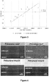
- microstructures of the protective coatings obtained from new or recycled mother liquor are similar in all respects during observations in Scanning Electron Microscopy (SEM). Each coating is dense, compact and homogeneous in thickness over the entire surface of the sample, as shown in FIG. Figure 4 .
- the interface with the substrate Si is well defined.
- they in top view (see Figure 5 ), they have the same very smooth appearance without major heterogeneities but with some elements of surface pollution.
- the maximum thicknesses achieved with the new precursor are significantly greater than those with the recycled precursor because the concentration of the recycled solution was lower. Since a lot of precursor is consumed in the reactor, only a small part is recovered thanks to the cryogenic trap.
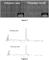
- the EDS spectra are also comparable, with a slight visible oxygen pollution in both cases, new precursor or recycled precursor.
- the peaks of chromium and carbon have identical intensities, as shown by the spectra in Figure 6 .
- the C / Cr ratio is 0.43 for Cr 7 C 3 and 0.66 for Cr 3 C 2 .
- the average composition observed is therefore very close to Cr 7 C 3 .
- Examples of diffractograms obtained for a deposit from new and recycled precursor are presented in Figure 7 .
- the nano-indentation measurements were made on samples coated with new precursor (3.5 ⁇ m thick) and recycled (1 ⁇ m thick).
- the calculations made by the measurement and analysis software take into account a coating Poisson's ratio of 0.2. Hardness and Young's modulus measurements are shown in Table 2.
- a deposition device by DLI-MOCVD that may be suitable for the implementation of the deposition steps a) and b) of the method of the invention is for example described in its main features in the document WO 2008009714 .
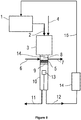
- the DLI-MOCVD device that can be used for the deposition of the protective coating with the deposition process of the invention according to steps a) to d) mainly comprises a feed tank, an evaporator, an injector, a CVD reactor and a unit for collecting the daughter solution for recycling into the device.
- This DLI-MOCVD device is described more specifically with reference to the Figure 8 .
- a pressurized feed tank 1 feeds the injector 2 in mother solution.
- the injector 2 is most often constituted of a commercial pulsed injection system, for example a diesel automobile injector.
- the opening and closing of the injector 2 can be controlled by computer, which allows the injection of the mother solution into the evaporator 3.
- the evaporator 3 is positioned co-axially above the generally vertical CVD deposition chamber 10 into which it opens.
- a carrier gas supply line 4 opens into the evaporator 3 next to the outlet of the injector 2.
- the carrier gas stream causes the vaporized stock solution from the evaporator 3 to the CVD deposit chamber 10.
- This grid 9 allows a good distribution of the gas stream in the CVD deposition chamber 10, which contributes to obtaining a good surface finish of the coatings and uniformity of thickness.
- a slide valve 5 can isolate the evaporator 3 from the rest of the CVD deposition chamber 10: the volume thus delimited below the slide valve 5 comprises the CVD reactor itself, in which the susceptor 13 on which the substrate is placed is located. to cover.
- the annex pipe 6 above the slide valve 5 allows the arrival of a reactive gas such as for example a carbon incorporation inhibitor.
- the annex pipe 7 above the slide valve 5 allows the evaporation pump 3 to be pumped during the purging or cleaning cycles of the latter.
- the flange 14 on which the branch lines of the associated pipelines 6 and 7 are made, as well as the gate valve 5 at the inlet of the CVD reactor, are heated to a temperature close to that of the evaporator 3.
- a protective layer is deposited on the substrate from the stock solution vaporized in the CVD reactor.
- an outlet 12 at the outlet of the CVD deposition chamber 10 collects a fraction of the gaseous effluent produced during the reaction.
- This fraction comprises the non-consumed bis (arene) precursor, the aromatic byproducts of the precursor and the solvent or, if appropriate, the carbon incorporation inhibitor.
- the outlet 12 opens onto a selective condensation unit 14 (such as for example a cryogenic trap), in which the main undesirable compounds (in particular the light hydrocarbons) of the fraction of the gaseous effluent are removed in order to produce a solution. girl.
- a selective condensation unit 14 such as for example a cryogenic trap
- a pipe 15 continuously conveys the daughter solution thus produced for recycling in the feed tank 1.
- a new mother solution is then formed for use in a new cycle of the deposition process of the invention.
- a primary pump 11 can be used to purge the entire DLI-MOCVD device, for example before a new deposit.
Landscapes
- Chemical & Material Sciences (AREA)
- Chemical Kinetics & Catalysis (AREA)
- Engineering & Computer Science (AREA)
- Mechanical Engineering (AREA)
- General Chemical & Material Sciences (AREA)
- Materials Engineering (AREA)
- Metallurgy (AREA)
- Organic Chemistry (AREA)
- Inorganic Chemistry (AREA)
- Dispersion Chemistry (AREA)
- Physics & Mathematics (AREA)
- Plasma & Fusion (AREA)
- Chemical Vapour Deposition (AREA)
Applications Claiming Priority (2)
| Application Number | Priority Date | Filing Date | Title |
|---|---|---|---|
| FR1562862A FR3045673B1 (fr) | 2015-12-18 | 2015-12-18 | Procede de depot d'un revetement par dli-mocvd avec recyclage du compose precurseur |
| PCT/FR2016/053541 WO2017103546A1 (fr) | 2015-12-18 | 2016-12-17 | Procede de depot d'un revetement par dli-mocvd avec recyclage direct du compose precurseur |
Publications (2)
| Publication Number | Publication Date |
|---|---|
| EP3390686A1 EP3390686A1 (fr) | 2018-10-24 |
| EP3390686B1 true EP3390686B1 (fr) | 2019-11-20 |
Family
ID=55948887
Family Applications (1)
| Application Number | Title | Priority Date | Filing Date |
|---|---|---|---|
| EP16831495.3A Active EP3390686B1 (fr) | 2015-12-18 | 2016-12-17 | Procede de depot d'un revetement par dli-mocvd avec recyclage direct du compose precurseur. |
Country Status (7)
| Country | Link |
|---|---|
| US (2) | US20190003048A1 (enExample) |
| EP (1) | EP3390686B1 (enExample) |
| JP (1) | JP6997711B2 (enExample) |
| KR (1) | KR20180089515A (enExample) |
| FR (1) | FR3045673B1 (enExample) |
| RU (1) | RU2699126C1 (enExample) |
| WO (1) | WO2017103546A1 (enExample) |
Families Citing this family (7)
| Publication number | Priority date | Publication date | Assignee | Title |
|---|---|---|---|---|
| ES2827830T3 (es) | 2016-09-28 | 2021-05-24 | Commissariat Energie Atomique | Componente nuclear con sustrato metálico, procedimiento de fabricación mediante DLI-MOCVD y usos contra la oxidación/hidruración |
| US11715572B2 (en) | 2016-09-28 | 2023-08-01 | Commissariat A L'energie Atomique Et Aux Energies Alternatives | Composite nuclear component, DLI-MOCVD method for producing same, and uses for controlling oxidation/hydridation |
| WO2018060642A1 (fr) | 2016-09-28 | 2018-04-05 | Commissariat A L'energie Atomique Et Aux Energies Alternatives | Composant nucléaire avec revetement de crc amorphe, procédé de fabrication par dli-mocvd et utilisations contre l'oxydation/hydruration |
| EP3520118B1 (fr) | 2016-09-28 | 2020-08-05 | Commissariat à l'Énergie Atomique et aux Énergies Alternatives | Composant nucléaire avec revetement de cr metastable, procédé de fabrication par dli-mocvd et utilisations contre l'oxydation/hydruration |
| US11560625B2 (en) * | 2018-01-19 | 2023-01-24 | Entegris, Inc. | Vapor deposition of molybdenum using a bis(alkyl-arene) molybdenum precursor |
| JP2021536528A (ja) * | 2018-09-03 | 2021-12-27 | アプライド マテリアルズ インコーポレイテッドApplied Materials, Incorporated | 薄膜堆積のための直接液体注入システム |
| FR3114588B1 (fr) * | 2020-09-29 | 2023-08-11 | Safran Ceram | Procédé de fabrication d’une barrière environnementale |
Family Cites Families (13)
| Publication number | Priority date | Publication date | Assignee | Title |
|---|---|---|---|---|
| SU1453950A1 (ru) * | 1987-01-07 | 1994-06-30 | А.И. Костылев | Парогазовая смесь для пиролитического нанесения защитных покрытий на основе хрома |
| FR2643071B1 (fr) * | 1989-02-16 | 1993-05-07 | Unirec | Procede de depot en phase vapeur a basse temperature d'un revetement ceramique du type nitrure ou carbonitrure metallique |
| SU1759958A1 (ru) * | 1990-04-19 | 1992-09-07 | Дзержинский филиал Ленинградского научно-исследовательского и конструкторского института химического машиностроения | Способ нанесени пиролитического карбидохромового покрыти на металлические поверхности |
| JPH0412525A (ja) * | 1990-05-02 | 1992-01-17 | Babcock Hitachi Kk | 有機金属化学気相成長装置 |
| WO2005028704A1 (en) * | 2003-09-19 | 2005-03-31 | Akzo Nobel N.V. | Metallization of substrate (s) by a liquid/vapor deposition process |
| KR101388817B1 (ko) * | 2006-03-14 | 2014-04-23 | 프랙스에어 테크놀로지, 인코포레이티드 | 증착 방법을 위한 온도 제어 콜드 트랩 및 그의 용도 |
| FR2904007B1 (fr) | 2006-07-21 | 2008-11-21 | Toulouse Inst Nat Polytech | Procede de depot de revetements ceramiques non oxydes. |
| FR2904006B1 (fr) * | 2006-07-21 | 2008-10-31 | Toulouse Inst Nat Polytech | Procede de depot de revetements metalliques durs |
| JP5277784B2 (ja) * | 2008-08-07 | 2013-08-28 | 東京エレクトロン株式会社 | 原料回収方法、トラップ機構、排気系及びこれを用いた成膜装置 |
| RU2513496C2 (ru) * | 2012-05-31 | 2014-04-20 | Федеральное государственное унитарное предприятие "Научно-производственное объединение "Радиевый институт имени В.Г. Хлопина" | Износостойкое металлическое покрытие на основе хрома и способ его нанесения |
| WO2014074589A1 (en) * | 2012-11-06 | 2014-05-15 | Applied Materials, Inc. | Apparatus for spatial atomic layer deposition with recirculation and methods of use |
| JP6101958B2 (ja) * | 2013-02-13 | 2017-03-29 | 日本パイオニクス株式会社 | アンモニア及び水素の回収方法及び再利用方法 |
| JP2015151564A (ja) * | 2014-02-13 | 2015-08-24 | 東洋製罐グループホールディングス株式会社 | 原子層堆積成膜装置 |
-
2015
- 2015-12-18 FR FR1562862A patent/FR3045673B1/fr active Active
-
2016
- 2016-12-17 US US16/063,405 patent/US20190003048A1/en not_active Abandoned
- 2016-12-17 RU RU2018125304A patent/RU2699126C1/ru not_active IP Right Cessation
- 2016-12-17 EP EP16831495.3A patent/EP3390686B1/fr active Active
- 2016-12-17 WO PCT/FR2016/053541 patent/WO2017103546A1/fr not_active Ceased
- 2016-12-17 JP JP2018531355A patent/JP6997711B2/ja active Active
- 2016-12-17 KR KR1020187020519A patent/KR20180089515A/ko not_active Ceased
-
2019
- 2019-10-31 US US16/669,854 patent/US11142822B2/en active Active
Non-Patent Citations (1)
| Title |
|---|
| None * |
Also Published As
| Publication number | Publication date |
|---|---|
| US20190003048A1 (en) | 2019-01-03 |
| EP3390686A1 (fr) | 2018-10-24 |
| FR3045673A1 (fr) | 2017-06-23 |
| KR20180089515A (ko) | 2018-08-08 |
| WO2017103546A1 (fr) | 2017-06-22 |
| RU2699126C1 (ru) | 2019-09-03 |
| JP6997711B2 (ja) | 2022-02-04 |
| US20200123655A1 (en) | 2020-04-23 |
| JP2019502023A (ja) | 2019-01-24 |
| FR3045673B1 (fr) | 2020-02-28 |
| US11142822B2 (en) | 2021-10-12 |
Similar Documents
| Publication | Publication Date | Title |
|---|---|---|
| EP3390686B1 (fr) | Procede de depot d'un revetement par dli-mocvd avec recyclage direct du compose precurseur. | |
| EP2250298B1 (fr) | Procede et systeme de depot d'un metal ou metalloïde sur des nanotubes de carbone | |
| EP2899295B1 (fr) | Procédé de réalisation par ALD d'une couche mince de formule MYx | |
| Thurier et al. | Platinum OMCVD processes and precursor chemistry | |
| EP2049706A1 (fr) | Procede de depot de revetements metalliques durs | |
| EP2387626B1 (fr) | Complexes organometalliques pour le depot chimique en phase vapeur de platine | |
| WO2018060642A1 (fr) | Composant nucléaire avec revetement de crc amorphe, procédé de fabrication par dli-mocvd et utilisations contre l'oxydation/hydruration | |
| Gebhard et al. | An efficient PE-ALD process for TiO 2 thin films employing a new Ti-precursor | |
| WO2018060643A1 (fr) | Composant nucléaire avec revetement de cr metastable, procédé de fabrication par dli-mocvd et utilisations contre l'oxydation/hydruration | |
| EP3519604B1 (fr) | Composant nucléaire a substrat metallique, procédé de fabrication par dli-mocvd et utilisations contre l'oxydation/hydruration | |
| WO2018060644A1 (fr) | Composant nucléaire composite, procédé de fabrication par dli-mocvd et utilisations contre l'oxydation/hydruration | |
| WO2008009715A9 (fr) | Procede de depot de revetements ceramiques non oxydes | |
| EP3049545B1 (fr) | Procédé de dépôt d'un revêtement protecteur contre la corrosion | |
| WO2009037397A1 (fr) | Procede de preparation d'un materiau nanocomposite par depot chimique en phase vapeur | |
| EP3109201A1 (fr) | Matériau biphasique à base de silice et de nanotubes de carbone | |
| Kalam et al. | Properties of tin oxide films grown by atomic layer deposition from tin tetraiodide and ozone | |
| FR2784694A1 (fr) | Procede de preparation par depot chimique en phase vapeur assiste par plasma (pacvd) de revetements a base de titane | |
| FR3056815A1 (fr) | Composant nucleaire a substrat metallique et utilisations contre l'oxydation/hydruration. | |
| FR3056601A1 (fr) | Procede de fabrication d'un composant nucleaire a substrat metallique par dli-mocvd. | |
| FR3056816A1 (fr) | Composant nucleaire avec revetement de crc amorphe, utilisations contre l'oxydation/hydruration. | |
| FR3056604A1 (fr) | Procede de fabrication par dli-mocvd d'un composant nucleaire composite. | |
| FR2928938A1 (fr) | Procede et systeme de depot d'un metal ou metalloide sur des nanotubes de carbone | |
| FR3056602A1 (fr) | Procede de fabrication par dli-mocvd d'un composant nucleaire avec revetement de crc amorphe. | |
| TW202417670A (zh) | 製備含過渡金屬之膜之方法 | |
| EP3795714A1 (en) | Process for the generation of aluminum-containing films |
Legal Events
| Date | Code | Title | Description |
|---|---|---|---|
| STAA | Information on the status of an ep patent application or granted ep patent |
Free format text: STATUS: UNKNOWN |
|
| STAA | Information on the status of an ep patent application or granted ep patent |
Free format text: STATUS: THE INTERNATIONAL PUBLICATION HAS BEEN MADE |
|
| PUAI | Public reference made under article 153(3) epc to a published international application that has entered the european phase |
Free format text: ORIGINAL CODE: 0009012 |
|
| STAA | Information on the status of an ep patent application or granted ep patent |
Free format text: STATUS: REQUEST FOR EXAMINATION WAS MADE |
|
| 17P | Request for examination filed |
Effective date: 20180717 |
|
| AK | Designated contracting states |
Kind code of ref document: A1 Designated state(s): AL AT BE BG CH CY CZ DE DK EE ES FI FR GB GR HR HU IE IS IT LI LT LU LV MC MK MT NL NO PL PT RO RS SE SI SK SM TR |
|
| AX | Request for extension of the european patent |
Extension state: BA ME |
|
| RAP1 | Party data changed (applicant data changed or rights of an application transferred) |
Owner name: COMMISSARIAT A L'ENERGIE ATOMIQUE ET AUX ENERGIES Owner name: INSTITUT NATIONAL POLYTECHNIQUE DE TOULOUSE |
|
| REG | Reference to a national code |
Ref country code: DE Ref legal event code: R079 Ref document number: 602016024851 Country of ref document: DE Free format text: PREVIOUS MAIN CLASS: C23C0016448000 Ipc: B01D0008000000 |
|
| DAV | Request for validation of the european patent (deleted) | ||
| DAX | Request for extension of the european patent (deleted) | ||
| GRAP | Despatch of communication of intention to grant a patent |
Free format text: ORIGINAL CODE: EPIDOSNIGR1 |
|
| RIC1 | Information provided on ipc code assigned before grant |
Ipc: B01D 8/00 20060101AFI20190326BHEP Ipc: C23C 16/32 20060101ALI20190326BHEP Ipc: B01D 5/00 20060101ALI20190326BHEP Ipc: C23C 16/18 20060101ALI20190326BHEP Ipc: C23C 16/44 20060101ALI20190326BHEP Ipc: C23C 16/448 20060101ALI20190326BHEP |
|
| STAA | Information on the status of an ep patent application or granted ep patent |
Free format text: STATUS: GRANT OF PATENT IS INTENDED |
|
| INTG | Intention to grant announced |
Effective date: 20190502 |
|
| RAP1 | Party data changed (applicant data changed or rights of an application transferred) |
Owner name: COMMISSARIAT A L'ENERGIE ATOMIQUE ET AUX ENERGIES Owner name: INSTITUT NATIONAL POLYTECHNIQUE DE TOULOUSE |
|
| GRAS | Grant fee paid |
Free format text: ORIGINAL CODE: EPIDOSNIGR3 |
|
| GRAJ | Information related to disapproval of communication of intention to grant by the applicant or resumption of examination proceedings by the epo deleted |
Free format text: ORIGINAL CODE: EPIDOSDIGR1 |
|
| GRAL | Information related to payment of fee for publishing/printing deleted |
Free format text: ORIGINAL CODE: EPIDOSDIGR3 |
|
| STAA | Information on the status of an ep patent application or granted ep patent |
Free format text: STATUS: REQUEST FOR EXAMINATION WAS MADE |
|
| GRAP | Despatch of communication of intention to grant a patent |
Free format text: ORIGINAL CODE: EPIDOSNIGR1 |
|
| STAA | Information on the status of an ep patent application or granted ep patent |
Free format text: STATUS: GRANT OF PATENT IS INTENDED |
|
| INTC | Intention to grant announced (deleted) | ||
| GRAA | (expected) grant |
Free format text: ORIGINAL CODE: 0009210 |
|
| STAA | Information on the status of an ep patent application or granted ep patent |
Free format text: STATUS: THE PATENT HAS BEEN GRANTED |
|
| INTG | Intention to grant announced |
Effective date: 20191002 |
|
| AK | Designated contracting states |
Kind code of ref document: B1 Designated state(s): AL AT BE BG CH CY CZ DE DK EE ES FI FR GB GR HR HU IE IS IT LI LT LU LV MC MK MT NL NO PL PT RO RS SE SI SK SM TR |
|
| REG | Reference to a national code |
Ref country code: GB Ref legal event code: FG4D Free format text: NOT ENGLISH |
|
| REG | Reference to a national code |
Ref country code: CH Ref legal event code: EP |
|
| REG | Reference to a national code |
Ref country code: DE Ref legal event code: R096 Ref document number: 602016024851 Country of ref document: DE |
|
| REG | Reference to a national code |
Ref country code: IE Ref legal event code: FG4D Free format text: LANGUAGE OF EP DOCUMENT: FRENCH |
|
| REG | Reference to a national code |
Ref country code: CH Ref legal event code: NV Representative=s name: DENNEMEYER AG, CH |
|
| REG | Reference to a national code |
Ref country code: AT Ref legal event code: REF Ref document number: 1203558 Country of ref document: AT Kind code of ref document: T Effective date: 20191215 |
|
| REG | Reference to a national code |
Ref country code: NL Ref legal event code: MP Effective date: 20191120 |
|
| REG | Reference to a national code |
Ref country code: LT Ref legal event code: MG4D |
|
| PG25 | Lapsed in a contracting state [announced via postgrant information from national office to epo] |
Ref country code: LT Free format text: LAPSE BECAUSE OF FAILURE TO SUBMIT A TRANSLATION OF THE DESCRIPTION OR TO PAY THE FEE WITHIN THE PRESCRIBED TIME-LIMIT Effective date: 20191120 Ref country code: NO Free format text: LAPSE BECAUSE OF FAILURE TO SUBMIT A TRANSLATION OF THE DESCRIPTION OR TO PAY THE FEE WITHIN THE PRESCRIBED TIME-LIMIT Effective date: 20200220 Ref country code: GR Free format text: LAPSE BECAUSE OF FAILURE TO SUBMIT A TRANSLATION OF THE DESCRIPTION OR TO PAY THE FEE WITHIN THE PRESCRIBED TIME-LIMIT Effective date: 20200221 Ref country code: LV Free format text: LAPSE BECAUSE OF FAILURE TO SUBMIT A TRANSLATION OF THE DESCRIPTION OR TO PAY THE FEE WITHIN THE PRESCRIBED TIME-LIMIT Effective date: 20191120 Ref country code: SE Free format text: LAPSE BECAUSE OF FAILURE TO SUBMIT A TRANSLATION OF THE DESCRIPTION OR TO PAY THE FEE WITHIN THE PRESCRIBED TIME-LIMIT Effective date: 20191120 Ref country code: BG Free format text: LAPSE BECAUSE OF FAILURE TO SUBMIT A TRANSLATION OF THE DESCRIPTION OR TO PAY THE FEE WITHIN THE PRESCRIBED TIME-LIMIT Effective date: 20200220 Ref country code: FI Free format text: LAPSE BECAUSE OF FAILURE TO SUBMIT A TRANSLATION OF THE DESCRIPTION OR TO PAY THE FEE WITHIN THE PRESCRIBED TIME-LIMIT Effective date: 20191120 Ref country code: NL Free format text: LAPSE BECAUSE OF FAILURE TO SUBMIT A TRANSLATION OF THE DESCRIPTION OR TO PAY THE FEE WITHIN THE PRESCRIBED TIME-LIMIT Effective date: 20191120 |
|
| PG25 | Lapsed in a contracting state [announced via postgrant information from national office to epo] |
Ref country code: HR Free format text: LAPSE BECAUSE OF FAILURE TO SUBMIT A TRANSLATION OF THE DESCRIPTION OR TO PAY THE FEE WITHIN THE PRESCRIBED TIME-LIMIT Effective date: 20191120 Ref country code: IS Free format text: LAPSE BECAUSE OF FAILURE TO SUBMIT A TRANSLATION OF THE DESCRIPTION OR TO PAY THE FEE WITHIN THE PRESCRIBED TIME-LIMIT Effective date: 20200320 Ref country code: RS Free format text: LAPSE BECAUSE OF FAILURE TO SUBMIT A TRANSLATION OF THE DESCRIPTION OR TO PAY THE FEE WITHIN THE PRESCRIBED TIME-LIMIT Effective date: 20191120 |
|
| PG25 | Lapsed in a contracting state [announced via postgrant information from national office to epo] |
Ref country code: AL Free format text: LAPSE BECAUSE OF FAILURE TO SUBMIT A TRANSLATION OF THE DESCRIPTION OR TO PAY THE FEE WITHIN THE PRESCRIBED TIME-LIMIT Effective date: 20191120 |
|
| PG25 | Lapsed in a contracting state [announced via postgrant information from national office to epo] |
Ref country code: ES Free format text: LAPSE BECAUSE OF FAILURE TO SUBMIT A TRANSLATION OF THE DESCRIPTION OR TO PAY THE FEE WITHIN THE PRESCRIBED TIME-LIMIT Effective date: 20191120 Ref country code: RO Free format text: LAPSE BECAUSE OF FAILURE TO SUBMIT A TRANSLATION OF THE DESCRIPTION OR TO PAY THE FEE WITHIN THE PRESCRIBED TIME-LIMIT Effective date: 20191120 Ref country code: CZ Free format text: LAPSE BECAUSE OF FAILURE TO SUBMIT A TRANSLATION OF THE DESCRIPTION OR TO PAY THE FEE WITHIN THE PRESCRIBED TIME-LIMIT Effective date: 20191120 Ref country code: PT Free format text: LAPSE BECAUSE OF FAILURE TO SUBMIT A TRANSLATION OF THE DESCRIPTION OR TO PAY THE FEE WITHIN THE PRESCRIBED TIME-LIMIT Effective date: 20200412 Ref country code: EE Free format text: LAPSE BECAUSE OF FAILURE TO SUBMIT A TRANSLATION OF THE DESCRIPTION OR TO PAY THE FEE WITHIN THE PRESCRIBED TIME-LIMIT Effective date: 20191120 Ref country code: DK Free format text: LAPSE BECAUSE OF FAILURE TO SUBMIT A TRANSLATION OF THE DESCRIPTION OR TO PAY THE FEE WITHIN THE PRESCRIBED TIME-LIMIT Effective date: 20191120 |
|
| REG | Reference to a national code |
Ref country code: DE Ref legal event code: R097 Ref document number: 602016024851 Country of ref document: DE |
|
| REG | Reference to a national code |
Ref country code: BE Ref legal event code: MM Effective date: 20191231 |
|
| PG25 | Lapsed in a contracting state [announced via postgrant information from national office to epo] |
Ref country code: SM Free format text: LAPSE BECAUSE OF FAILURE TO SUBMIT A TRANSLATION OF THE DESCRIPTION OR TO PAY THE FEE WITHIN THE PRESCRIBED TIME-LIMIT Effective date: 20191120 Ref country code: SK Free format text: LAPSE BECAUSE OF FAILURE TO SUBMIT A TRANSLATION OF THE DESCRIPTION OR TO PAY THE FEE WITHIN THE PRESCRIBED TIME-LIMIT Effective date: 20191120 Ref country code: MC Free format text: LAPSE BECAUSE OF FAILURE TO SUBMIT A TRANSLATION OF THE DESCRIPTION OR TO PAY THE FEE WITHIN THE PRESCRIBED TIME-LIMIT Effective date: 20191120 |
|
| PLBE | No opposition filed within time limit |
Free format text: ORIGINAL CODE: 0009261 |
|
| STAA | Information on the status of an ep patent application or granted ep patent |
Free format text: STATUS: NO OPPOSITION FILED WITHIN TIME LIMIT |
|
| 26N | No opposition filed |
Effective date: 20200821 |
|
| PG25 | Lapsed in a contracting state [announced via postgrant information from national office to epo] |
Ref country code: LU Free format text: LAPSE BECAUSE OF NON-PAYMENT OF DUE FEES Effective date: 20191217 Ref country code: IE Free format text: LAPSE BECAUSE OF NON-PAYMENT OF DUE FEES Effective date: 20191217 |
|
| PG25 | Lapsed in a contracting state [announced via postgrant information from national office to epo] |
Ref country code: SI Free format text: LAPSE BECAUSE OF FAILURE TO SUBMIT A TRANSLATION OF THE DESCRIPTION OR TO PAY THE FEE WITHIN THE PRESCRIBED TIME-LIMIT Effective date: 20191120 Ref country code: PL Free format text: LAPSE BECAUSE OF FAILURE TO SUBMIT A TRANSLATION OF THE DESCRIPTION OR TO PAY THE FEE WITHIN THE PRESCRIBED TIME-LIMIT Effective date: 20191120 Ref country code: BE Free format text: LAPSE BECAUSE OF NON-PAYMENT OF DUE FEES Effective date: 20191231 |
|
| PG25 | Lapsed in a contracting state [announced via postgrant information from national office to epo] |
Ref country code: IT Free format text: LAPSE BECAUSE OF FAILURE TO SUBMIT A TRANSLATION OF THE DESCRIPTION OR TO PAY THE FEE WITHIN THE PRESCRIBED TIME-LIMIT Effective date: 20191120 |
|
| PG25 | Lapsed in a contracting state [announced via postgrant information from national office to epo] |
Ref country code: CY Free format text: LAPSE BECAUSE OF FAILURE TO SUBMIT A TRANSLATION OF THE DESCRIPTION OR TO PAY THE FEE WITHIN THE PRESCRIBED TIME-LIMIT Effective date: 20191120 |
|
| PG25 | Lapsed in a contracting state [announced via postgrant information from national office to epo] |
Ref country code: MT Free format text: LAPSE BECAUSE OF FAILURE TO SUBMIT A TRANSLATION OF THE DESCRIPTION OR TO PAY THE FEE WITHIN THE PRESCRIBED TIME-LIMIT Effective date: 20191120 Ref country code: HU Free format text: LAPSE BECAUSE OF FAILURE TO SUBMIT A TRANSLATION OF THE DESCRIPTION OR TO PAY THE FEE WITHIN THE PRESCRIBED TIME-LIMIT; INVALID AB INITIO Effective date: 20161217 |
|
| REG | Reference to a national code |
Ref country code: AT Ref legal event code: UEP Ref document number: 1203558 Country of ref document: AT Kind code of ref document: T Effective date: 20191120 |
|
| PG25 | Lapsed in a contracting state [announced via postgrant information from national office to epo] |
Ref country code: TR Free format text: LAPSE BECAUSE OF FAILURE TO SUBMIT A TRANSLATION OF THE DESCRIPTION OR TO PAY THE FEE WITHIN THE PRESCRIBED TIME-LIMIT Effective date: 20191120 |
|
| PG25 | Lapsed in a contracting state [announced via postgrant information from national office to epo] |
Ref country code: MK Free format text: LAPSE BECAUSE OF FAILURE TO SUBMIT A TRANSLATION OF THE DESCRIPTION OR TO PAY THE FEE WITHIN THE PRESCRIBED TIME-LIMIT Effective date: 20191120 |
|
| PGFP | Annual fee paid to national office [announced via postgrant information from national office to epo] |
Ref country code: GB Payment date: 20241227 Year of fee payment: 9 |
|
| PGFP | Annual fee paid to national office [announced via postgrant information from national office to epo] |
Ref country code: FR Payment date: 20241227 Year of fee payment: 9 |
|
| PGFP | Annual fee paid to national office [announced via postgrant information from national office to epo] |
Ref country code: AT Payment date: 20241213 Year of fee payment: 9 |
|
| PGFP | Annual fee paid to national office [announced via postgrant information from national office to epo] |
Ref country code: DE Payment date: 20241219 Year of fee payment: 9 |
|
| PGFP | Annual fee paid to national office [announced via postgrant information from national office to epo] |
Ref country code: CH Payment date: 20250101 Year of fee payment: 9 |