EP3387485B1 - Vorrichtungen und verfahren zum ziehen von brillen - Google Patents
Vorrichtungen und verfahren zum ziehen von brillen Download PDFInfo
- Publication number
- EP3387485B1 EP3387485B1 EP16873847.4A EP16873847A EP3387485B1 EP 3387485 B1 EP3387485 B1 EP 3387485B1 EP 16873847 A EP16873847 A EP 16873847A EP 3387485 B1 EP3387485 B1 EP 3387485B1
- Authority
- EP
- European Patent Office
- Prior art keywords
- traction
- user
- eyewear
- contact
- force
- Prior art date
- Legal status (The legal status is an assumption and is not a legal conclusion. Google has not performed a legal analysis and makes no representation as to the accuracy of the status listed.)
- Active
Links
Images


Classifications
-
- G—PHYSICS
- G02—OPTICS
- G02C—SPECTACLES; SUNGLASSES OR GOGGLES INSOFAR AS THEY HAVE THE SAME FEATURES AS SPECTACLES; CONTACT LENSES
- G02C3/00—Special supporting arrangements for lens assemblies or monocles
- G02C3/003—Arrangements for fitting and securing to the head in the position of use
-
- G—PHYSICS
- G02—OPTICS
- G02C—SPECTACLES; SUNGLASSES OR GOGGLES INSOFAR AS THEY HAVE THE SAME FEATURES AS SPECTACLES; CONTACT LENSES
- G02C2200/00—Generic mechanical aspects applicable to one or more of the groups G02C1/00 - G02C5/00 and G02C9/00 - G02C13/00 and their subgroups
- G02C2200/20—Friction elements
-
- G—PHYSICS
- G02—OPTICS
- G02C—SPECTACLES; SUNGLASSES OR GOGGLES INSOFAR AS THEY HAVE THE SAME FEATURES AS SPECTACLES; CONTACT LENSES
- G02C5/00—Constructions of non-optical parts
- G02C5/12—Nose pads; Nose-engaging surfaces of bridges or rims
-
- G—PHYSICS
- G02—OPTICS
- G02C—SPECTACLES; SUNGLASSES OR GOGGLES INSOFAR AS THEY HAVE THE SAME FEATURES AS SPECTACLES; CONTACT LENSES
- G02C5/00—Constructions of non-optical parts
- G02C5/14—Side-members
- G02C5/143—Side-members having special ear pieces
Definitions
- the embodiments described herein relate generally to traction devices and methods for eyewear.
- some embodiments described herein relate to eyewear having traction devices which can assist in maintaining an eyewear on a head of a wearer in a particular position or orientation.
- the invention corresponds to the eyewear as defined in claim 1.
- the plurality of protrusions extending obliquely from the exterior surface can be more parallel with the exterior surface than perpendicular. In some embodiments, the plurality of protrusions extending obliquely from the exterior surface can be more perpendicular to the exterior surface than parallel. In some embodiments, the plurality of protrusions extending obliquely from the exterior surface can be generally equally perpendicular to the exterior surface as parallel.
- the traction surface exerts a traction force on a contact surface at a plurality of contact points within the contact surface, the traction force being configured to inhibit slipping of the eyewear on a user's head when worn.
- the traction surface when subject to a force in a first direction within a plane tangent to the contact surface at the contact point, exerts up to a first amount of traction force before slipping.
- the traction surface when subject to a force in a second direction within a plane tangent to the contact surface at the contact point, exerts up to a second amount of traction force before slipping.
- the first amount of traction force is greater than the second amount of traction force.
- the plurality of protrusions extending obliquely from the exterior surface can extend in a direction with a component generally opposite the first direction.
- the traction surface can be on at least the nosepiece and the contact surface is at least a portion of the user's nose.
- the first direction can extend generally downwardly and anteriorly relative to the user's nose and can form an acute angle with a first axis, the first axis being within a plane tangent to the contact surface at the one or more contact points and parallel to a horizontal axis.
- the one or more contact points can include a majority of contact points within the contact surface.
- the traction surface can be on at least the earstem and the contact surface is at least a portion of the user's ear.
- the first direction can extend generally anteriorly relative to a user's ear.
- the one or more contact points can include a majority of contact points within the contact surface.
- the traction surface can include a first portion and a second portion.
- the first portion of the traction surface when subject to a force in a first direction within a plane tangent to the first portion of the contact surface at the contact point, can exert up to a first amount of traction force before slipping and, when subject to a force in a second direction within a plane tangent to the first portion of the contact surface at the contact point, can exert up to a second amount of traction force before slipping, wherein the first amount of traction force is greater than the second amount of traction force.
- the second portion of the traction surface when subject to a force in a third direction within a plane tangent to the second portion of the contact surface at the contact point, can exert up to a third amount of traction force before slipping and, when subject to a force in a fourth direction within a plane tangent to the second portion of the contact surface at the contact point, can exert up to a fourth amount of traction force before slipping, wherein the third amount of traction force is greater than the fourth amount of traction force.
- the first direction can be different from the third direction.
- the traction surface is integrally formed on the support.
- the traction surface can be formed from the same material as the material of the portions of the support adjacent the traction surface.
- the traction surface can be formed on a traction member, wherein the traction member can be attached to the support.
- the traction member can be removably attached to the support. According to the invention the traction member can not be removably attached to the support.
- the traction surface can be on at least the nosepiece and the contact surface is at least a portion of the user's nose.
- the first direction extends generally downwardly and anteriorly relative to the user's nose and forms an acute angle with a first axis, the first axis being within a plane tangent to the contact surface at the one or more contact points and parallel to a horizontal axis.
- the traction surface can be on at least the earstem and the contact surface is at least a portion of the user's ear. In some embodiments, at one or more contact points within the contact surface, the first direction extends generally anteriorly relative to a user's ear.
- eyewear retention devices and methods provide aspects and features of eyewear retention devices and methods, in the context of several embodiments of devices and methods.
- eyewear and eyeglasses are general terms intended to be used in accordance with their ordinary meanings.
- these terms embrace any optical devices, such as those containing corrective lenses for defects in vision or lenses for such special purposes as filters for absorbing or blocking portions of the electromagnetic spectrum, providing physical shields for the eyes or making available other physical or optical functions for protective or visual assisting purposes.
- These embodiments are described and illustrated in connection with specific types of eyewear such as eyewear having dual lenses.
- Any feature, step, material, or structure described and/or illustrated in any embodiment can be used with or instead of any other feature, step, material, or structure described and/or illustrated in any other embodiment. Anything in this specification can be omitted in some embodiments; no features described or illustrated in this specification are essential or indispensable.
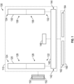
- Figures 1-3 are schematic illustrations of various embodiments of eyewear 100, 200, 300.
- the eyewear 100, 200, 300 can include one or more supports 110, 210, 310.
- the supports 110, 210, 310 can be configured to be supported on a head of a user or wearer.
- the eyewear 100, 200, 300 can also include one or more traction surfaces 150, 250a-c, 350a-c coupled to, according to examples not covered by the invention, or formed on or integrated into the one or more supports 110, 210, 310, according to the invention.
- the one or more traction surfaces 150, 250a-c, 350a-c is configured to retain the eyewear 100, 200, 300 on the user's face and resist or reduce the likelihood of slippage and/or removability in undesired directions while not resisting or allowing a greater degree of slippage and/or removability in desired directions. This can be beneficial in that the eyewear 100, 200, 300 will be less likely to slip while still allowing a user's to relatively easily remove the eyewear from the user's face.
- the one or more traction surfaces 150, 250a-c, 350a-c can be configured to retain the eyewear 100, 200, 300 on the user's nose and resist or reduce the likelihood of slippage and/or removability in one or more directions generally anteriorly and/or downwardly relative to the user's nose while not resisting or increasing the likelihood of slippage or removability in one or more generally or substantially opposite directions.
- the eyewear 100, 200, 300 is less likely to slip off the user's nose when being worn.
- the user can comfortably do so with little to no resistance.
- the one or more traction surfaces 150, 250a-c, 350a-c can be configured to retain the eyewear 100, 200, 300 on the user's ears and/or a lateral side of the user's head and reduce the likelihood of slippage in a direction generally anteriorly relative to the user's ears and/or the lateral side of the user's head or any other direction as desired. In this manner, the eyewear 100, 200, 300 is less likely to slip forward relative to the user's head when being worn. Moreover, when a user wishes to remove the eyewear from the user's head in a direction generally upwardly relative to the user's head, the user can comfortably do so with little to no resistance.
- the eyewear 100, 200, 300 can also include one or more lenses 160, 260, 360.
- the support 110 can include a right earstem 120, a left earstem 130, a face 140, and a nosepiece 146.
- the right earstem 120 can include an anterior end 122, a posterior end 124, an anterior portion 126, and a posterior portion 128.
- the left earstem 130 can similarly include an anterior end 132, a posterior end 134, an anterior portion 136, and a posterior portion 138.
- the face 140 can include a right side 142 and a left side 144 and be configured to support a lens 160, such as a right lens 162 and left lens 164.
- the face 140 can be configured to surround at least a portion or an entirety of the periphery of the lens 160 such as lenses 162, 164.
- the face 140 can include partial or full orbitals.
- the earstems such as right and/or left earstems 120, 130, the face 140 and/or the nosepiece 146 can be fabricated using one or more metals, polymers, or other relatively stiff and/or resilient materials that can have desirable lens securing and stabilizing properties while nevertheless enabling the eyewear to provide desirable flexural properties in the earstems, such as right and/or left earstems 120, 130 thereof.
- steel such as stainless, titanium and its alloys, carbon fiber, plastic, aluminum, polymers such as acetate, polyurethane, polyurea, polycarbonate, PC-ABS, ABS, PVC, nylon 6, nylon 6-6, and nylon12, and other such materials can be used in the earstems, such as right and/or left earstems 120, 130, the face 140, and/or the nosepiece 146 to provide superior mechanical properties while reducing the weight of the support 110.
- Any suitable metals, plastics or other rigid and/or resilient materials can be used to form the support 110 to provide exceptional rigidity, durability, and wear resistance.
- the lens 160 such as a right and/or left lens 162, 164, may take any of a number of configurations and can be formed of sheet plastic, molded plastic, glass, etc., as determined by the application of the lens.
- the right earstem 120, the left earstem 130, and/or the nosepiece 146 can be coupled to the face 140.
- the right earstem 120 can be coupled to the right side 142 of the face 140 at or proximate an anterior end 122 of the right earstem 120
- the left earstem 130 can be coupled to the left side 144 of the face 140 at or proximate an anterior end 132 of the left earstem 130
- the nosepiece 146 can be coupled to a portion of the face 140 between the right and left sides 142, 144.
- the right earstem 120, the left earstem 130, and/or the nosepiece 146 can be permanently affixed to the face 140.
- a permanent attachment of the earstems, such as right and/or left earstems 120, 130, and/or the nosepiece 146, to the face 140 may be accomplished, for example, through molding or thermoplastic bonding.
- the right earstem 120, the left earstem 130, and/or the nosepiece 146 can be rotatably coupled to the face 140 via a rotatable coupling such as, but not limited to, a snap fit coupling or fasteners including screws or pins or any other rotatable coupling as desired.
- the right and/or left earstems 120, 130 can rotate from an open position, in which the eyewear 100 can be worn by a user, to a closed position, in which the eyewear 100 takes on a more compact form factor for storage, and vice versa.
- the eyewear 100 includes a traction surface 150.
- the traction surface 150 is configured to retain the eyewear 100, on the user's face and resist or reduce the likelihood of removal or slippage in undesired directions.
- the traction surface 150 can be positioned on a traction member 152 and form at least a portion of an exterior surface of the traction member 152.
- the traction surface 150 can extend entirely around the periphery of the traction member 152 or can extend partially around the periphery of the traction member 152 such as along a bottom portion of the traction member 152, an inwardly facing portion of the traction member 152, and/or an outwardly facing portion of the traction member 152.
- the traction member 152 can be a component separate from the support 110.
- the retention member 152 can be coupled to a portion of the support 110.
- the retention system 150 can be coupled to the right earstem 120, the left earstem 130, the face 140, and/or a combination of these components of the support 110.
- the coupling between the traction member 152 and the support 110 can be such that the traction member 152 can be removable from the support 110.
- the traction member 152 can be coupled to the support 110 using removable fasteners such as threaded screws, threaded bolts, and the like.
- the traction member 152 can be coupled to the support 110 using removable fasteners such as a clip.
- the traction member 152 can be formed from a material which exerts some degree of tackiness or grip on a surface.
- the traction member 152 can be formed from materials such as, but not limited to polymers, such as acetate, polyurethane, polyurea, polycarbonate, PC-ABS, ABS, PVC, Nylon 6, Nylon 6-6, Nylon12, silicone, latex, and rubber, metals such as steel, titanium, titanium alloys, and aluminum, composites, plastics, a combination of the above materials, and/or any other material or combination of materials as desired.
- the materials can be 3D printed or injection molded.
- the traction member 152 can be retained on the support 110 via contact between the traction member 152 and the support 110.
- the traction member 152 can be coupled to the portion of the support 110 using one or more permanent affixation methods such as, but not limited to, overmolding, one or more adhesives, and the like. According to the invention the traction member 152 is unitarily formed with the portion of the support 110.
- the traction member 152 can have a length relative to another component of the eyewear 100 such as the support 110 or lens 160.
- the traction member 152 can have a length of between approximately 5% to approximately 60% of a length of an earstem, such as left and/or right earstems 120, 130, a length of between approximately 10% to approximately 50% of a length of an earstem, a length of between approximately 15% to approximately 40% of a length of an earstem, a length of between approximately 20% to approximately 30% of a length of an earstem, any sub-range within these ranges, or any percentage of the length of an earstem as desired, the length being a longitudinal length from an anterior end, such as anterior ends 122, 132, to a posterior end, such as posterior ends 124, 134.
- the traction member 152 can have a length approximately equal to that of the posterior portion, such as posterior portions 128, 138.
- the traction member 152 can have a length approximately equal to that
- the traction surface 150 can be configured to resist or to reduce or inhibit slippage between the support 110 and another surface in contact with the traction surface 150 such as, but not limited to, a user's skin in certain directions while resisting less or allowing a greater degree of slippage in other directions.
- the traction surface 150 can be configured such that the traction surface resists or reduces or inhibits slippage between the support 110 and the user's nose in a direction generally anteriorly and/or downwardly relative to the user's nose, while resisting less or allowing a greater degree of slippage in other directions, such as posteriorly and/or upwardly.
- the traction surface 150 can be configured such that the traction surface resists or reduces or inhibits slippage between the support 110 and the user's ear and/or a lateral side of the user's head in a direction generally anteriorly relative to the user's head while resisting less or allowing a greater degree of slippage in other directions, such as posteriorly, upwardly, and/or downwardly.
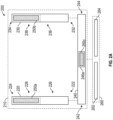
- an embodiment of an eyewear 200 is illustrated having a support 210.
- the eyewear 200 can include or share any or all of the components, features and/or characteristics described above in connection with eyewear 100.
- the support 210 can include a right earstem 220, a left earstem 230, a face 240 and a nosepiece, such as nosepieces 246a, 246b.
- the right earstem 220 can include an anterior end 222, a posterior end 224, an anterior portion 226, and a posterior portion 228.
- the left earstem 230 can similarly include an anterior end 232, a posterior end 234, an anterior portion 236, and a posterior portion 238.
- the face 240 can include a right side 242 and a left side 244 and be configured to support a lens 260, such as a right lens 262 and left lens 264.
- the face 240 can be configured to surround at least a portion or an entirety of the periphery of the lens 260 such as lenses 262, 264.
- the face 240 can include partial or full orbitals.
- the earstems such as right and/or left earstems 220, 230, the face 240 and/or the nosepieces 246a, 246b can be fabricated using one or more metals, polymers, or other relatively stiff and/or resilient materials that can have desirable lens securing and stabilizing properties while nevertheless enabling the eyewear to provide desirable flexural properties in the earstems, such as right and/or left earstems 220, 230 thereof.
- titanium, carbon fiber, plastic, aluminum, and other such materials can be used in the earstems, such as right and/or left earstems 220, 230, the face 240, and/or the nosepieces 246a, 246b to provide superior mechanical properties while reducing the weight of the support 210.
- Any suitable metals, plastics or other rigid and/or resilient materials can be used to form the support 210 to provide exceptional rigidity, durability, and wear resistance.
- various features and aspects disclosed herein can be used in eyewear fabricated from any material, e.g., plastic, acetate, composite, metal, etc., or any combination thereof.
- the lens 260 such as a right and/or left lens 262, 264, may take any of a number of configurations and can be formed of sheet plastic, molded plastic, glass, etc., as determined by the application of the lens.
- the right earstem 220, the left earstem 230, and/or the nosepieces 246a, 246b can be coupled to the face 240 and/or the lens 260.
- the right earstem 220 can be coupled to the right side 242 of the face 240 at or proximate an anterior end 222 of the right earstem 220
- the left earstem 230 can be coupled to the left side 244 of the face 240 at or proximate an anterior end 232 of the left earstem 230
- the nosepieces 246a, 246b can be coupled to a portion of the face 240 between the right and left sides 242, 244 and/or the lens 260 between lateral sides of the lens 260 or between two separate lenses, such as right and left lenses 262, 264.
- the right earstem 220, the left earstem 230, and/or the nosepieces 246a, 246b can be permanently affixed to the face 240 and/or the lens 260.
- a permanent attachment of the earstems, such as right and/or left earstems 220, 230 and/or the nosepieces 246a, 246b, to the face 240 and/or the lens 260 may be accomplished, for example, through molding or thermoplastic bonding.
- the nosepiece 246a can be a portion of the face 240 itself.
- the nosepiece 246b can be coupled to the lens 260 without coupling to the face 240.
- the right earstem 220, the left earstem 230, and/or the nosepiece 246a can be rotatably coupled to the face 240 via a rotatable coupling such as, but not limited to, a snap fit coupling or fasteners including screws or pins or any other rotatable coupling as desired.
- a rotatable coupling such as, but not limited to, a snap fit coupling or fasteners including screws or pins or any other rotatable coupling as desired.
- the right and/or left earstems 220, 230 are rotatably coupled to the face 240 and/or the lens 260, the right and/or left earstems 220, 230 can rotate from an open position, in which the eyewear 200 can be worn by a user, to a closed position, in which the eyewear 200 takes on a more compact form factor for storage, and vice versa.
- the eyewear 200 includes one or more traction surfaces 250a, 250b, 250c.
- the traction surfaces 250a, 250b, 250c is configured to retain the eyewear 200, on the user's face and resist or reduce the likelihood of removal or slippage in undesired directions.
- the traction surfaces 250a, 250b, 250c can be coupled to the right earstem 220, the left earstem 230, and/or the nosepieces 246a, 246b respectively.
- the traction surfaces 250a, 250b, 250c is formed on portions of the support 210.
- the traction surface 250a can be molded together with the right earstem 220
- the traction surface 250b can be molded together with the left earstem 230
- the traction surface 250c can be molded together with the nosepieces 246a, 246b respectively.
- one or more of traction surface 250a, 250b, 250c is integrally formed with one or more components of the support 210 such that the one or more traction surfaces 250a, 250b, 250c forms a unitary structure with one or more components of the support 210.
- the traction surfaces 250a, 250b, 250c can be monolithically formed from the same material as the components of the support 210 on which the traction surfaces 250a, 250b, 250c are formed. In some instances in which the traction surfaces 250a, 250b, 250c are molded together with one or more components of the support 210, the traction surfaces 250a, 250b, 250c can be formed from material different from the material of the components of the support 210 on which the traction surfaces 250a, 250b, 250c are formed.
- one or more of the traction surfaces can be separate from components of the support 210, such as earstems 220, 230.
- Such traction surfaces for example, may be slipped over portions of the support 210, such as earstems 220, 230.
- the traction surfaces 250a-c can extend entirely around the periphery of the components on which the traction surfaces 250a-c are formed or can extend partially around the periphery of the components on which the traction surfaces 250a-c are formed.
- traction surface 250a can extend entirely around the periphery of the right earstem 220 or can extend partially around the periphery such as along a bottom portion of the right earstem 220, an inwardly facing portion of the right earstem 220, and/or an outwardly facing portion of the right earstem 220.
- the traction surface 250b can include similar characteristics with respect to the left earstem 230.
- the traction surfaces 250a, 250b, 250c can have lengths relative to one or more components of the eyewear 200 such as the support 210 or lens 260.
- the traction surface 250a can have a length of between approximately 5% to approximately 60% of a length of the right earstem 220, a length of between approximately 10% to approximately 50% of a length of the right earstem 220, a length of between approximately 15% to approximately 40% of a length of the right earstem 220, a length of between approximately 20% to approximately 30% of a length of the right earstem 220, any sub-range within these ranges, or any percentage of the length of the right earstem 220 as desired, the length being a longitudinal length from the anterior end 222 to the posterior end 224.
- the traction surface 250a can extend at or proximate a posterior end 224 of the right earstem 220 and extend approximately to the midpoint of the right earstem 220.
- the traction surface 250b can have similar lengths relative to the left earstem 230.
- the traction surface 250c can have a length sufficient to extend along the entirety of the nosepieces 246a, 246b or a portion thereof.
- the traction surfaces 250a, 250b, 250c can be configured to resist or to reduce or inhibit slippage between the support 210 and another surface in contact with the traction surfaces 250a, 250b, 250c such as, but not limited to, a user's skin in certain directions while resisting less or allowing a greater degree of slippage in other directions.
- the traction surface can be configured such that the traction surface resists or reduces or inhibits slippage between the support 210 and the user's nose in a direction generally anteriorly and/or downwardly relative to the user's nose, while resisting less or allowing a greater degree of slippage in other directions, such as posteriorly and/or upwardly.
- the traction surface such as traction surfaces 250a, 250b, 250c
- the traction surface can be configured such that the traction surface resists or reduces or inhibits slippage between the support 210 and the user's ear and/or a lateral side of the user's head in a direction generally anteriorly relative to the user's head while resisting less or allowing a greater degree of slippage in other directions, such as posteriorly, upwardly, and/or downwardly.
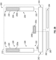
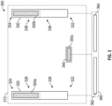
- an embodiment of an eyewear 300 is illustrated having a support 310.
- the eyewear 300 can include or share any or all of the components, features and/or characteristics described above in connection with eyewear 100, 200.
- the support 310 can include a right earstem 320, a left earstem 330, and a nosepiece 346.
- the right earstem 320 can include an anterior end 322, a posterior end 324, an anterior portion 326, and a posterior portion 328.
- the left earstem 330 can similarly include an anterior end 332, a posterior end 334, an anterior portion 336, and a posterior portion 338.
- the earstems such as right and/or left earstems 320, 330, and/or the nosepiece 346 can be fabricated using one or more metals, polymers, or other relatively stiff and/or resilient materials that can have desirable lens securing and stabilizing properties while nevertheless enabling the eyewear to provide desirable flexural properties in the earstems, such as right and/or left earstems 320, 330 thereof.
- metals, polymers, or other relatively stiff and/or resilient materials that can have desirable lens securing and stabilizing properties while nevertheless enabling the eyewear to provide desirable flexural properties in the earstems, such as right and/or left earstems 320, 330 thereof.
- titanium, carbon fiber, plastic, aluminum, and other such materials can be used in the earstems, such as right and/or left earstems 320, 330, and/or the nosepiece 346 to provide superior mechanical properties while reducing the weight of the support 310.
- any suitable metals, plastics or other rigid and/or resilient materials can be used to form the support 310 to provide exceptional rigidity, durability, and wear resistance. Nevertheless, various features and aspects disclosed herein can be used in eyewear fabricated from any material, e.g., plastic, acetate, composite, metal, etc., or any combination thereof.
- the lens 360 such as a right and/or left lens 362, 364, may take any of a number of configurations and can be formed of sheet plastic, molded plastic, glass, etc., as determined by the application of the lens.
- the right earstem 320, the left earstem 330, and/or the nosepiece 346 can be coupled to the 360.
- the right earstem 320 can be coupled to a right side of the lens 360 or to the right lens 362 at or proximate an anterior end 322 of the right earstem 320
- the left earstem 330 can be coupled to the left side of the lens 360 or to the left lens 364 at or proximate an anterior end 332 of the left earstem 330
- the nosepiece 346 can be coupled to a portion of the lens 360 between lateral sides of the lens 360 or between two separate lenses, such as right and left lenses 362, 364.
- the right earstem 320, the left earstem 330, and/or the nosepiece 346 can be permanently affixed to the lens 360.
- a permanent attachment of the earstems, such as right and/or left earstems 320, 230, and/or the nosepiece 346, to lens 360 may be accomplished, for example, through molding or thermoplastic bonding.
- the right earstem 320, the left earstem 330, and/or the nosepiece 346 can be rotatably coupled to the lens 360 via a rotatable coupling such as, but not limited to, a snap fit coupling or fasteners including screws or pins or any other rotatable coupling as desired.
- the right and/or left earstems 320, 330 can rotate from an open position, in which the eyewear 300 can be worn by a user, to a closed position, in which the eyewear 300 takes on a more compact form factor for storage, and vice versa.
- the eyewear 300 includes one or more traction surfaces 350a, 350b, 350c.
- the traction surfaces 350a, 350b, 350c is configured to retain the eyewear 300, on the user's face and resist or reduce the likelihood of removal or slippage in undesired directions.
- the traction surfaces 350a, 350b, 350c can be coupled to the right earstem 320, the left earstem 330, and/or the nosepiece 346 respectively.
- the traction surfaces 350a, 350b, 350c are formed on portions of the support 310.
- the traction surface 350a can be molded together with the right earstem 320
- the traction surface 350b can be molded together with the left earstem 330
- the traction surface 350c can be molded together with the nosepiece 346 respectively.
- one or more of traction surface 350a, 350b, 350c is integrally formed with one or more components of the support 310 such that the one or more traction surfaces 350a, 350b, 350c forms a unitary structure with one or more components of the support 310.
- the traction surfaces 350a, 350b, 350c can be monolithically formed from the same material as the components of the support 310 on which the traction surfaces 350a, 350b, 350c are formed. In some instances in which the traction surfaces 350a, 350b, 350c are molded together with one or more components of the support 310, the traction surfaces 350a, 350b, 350c can be formed from material different from the material of the components of the support 310 on which the traction surfaces 350a, 350b, 350c are formed.
- one or more of the traction surfaces can be separate from components of the support 310, such as earstems 320, 330.
- Such traction surfaces for example, may be slipped over portions of the support 310, such as earstems 320, 330.
- the traction surfaces 350a-c can extend entirely around the periphery of the components on which the traction surfaces 350a-c are formed or can extend partially around the periphery of the components on which the traction surfaces 350a-c are formed.
- traction surface 350a can extend entirely around the periphery of the right earstem 320 or can extend partially around the periphery such as along a bottom portion of the right earstem 320, an inwardly facing portion of the right earstem 320, and/or an outwardly facing portion of the right earstem 320.
- the traction surface 350b can include similar characteristics with respect to the left earstem 330.
- the traction surfaces 350a, 350b, 350c can have lengths relative to one or more components of the eyewear 300 such as the support 310 or lens 360.
- the traction surface 350a can have a length of between approximately 5% to approximately 60% of a length of the right earstem 320, a length of between approximately 10% to approximately 50% of a length of the right earstem 320, a length of between approximately 15% to approximately 40% of a length of the right earstem 320, a length of between approximately 20% to approximately 30% of a length of the right earstem 320, any sub-range within these ranges, or any percentage of the length of the right earstem 320 as desired, the length being a longitudinal length from the anterior end 322 to the posterior end 324.
- the traction surface 350a can extend at or proximate a posterior end 324 of the right earstem 320 and extend approximately to the midpoint of the right earstem 320.
- the traction surface 350b can have similar lengths relative to the left earstem 330.
- the traction surface 350c can have a length sufficient to extend along the entirety of the nosepiece 346 or a portion thereof.
- the traction surfaces 350a, 350b, 350c can be configured to resist or to reduce or inhibit slippage between the support 310 and another surface in contact with the traction surfaces 350a, 350b, 350c such as, but not limited to, a user's skin in certain directions while resisting less or allowing a greater degree of slippage in other directions.
- the traction surface can be configured such that the traction surface resists or reduces or inhibits slippage between the support 310 and the user's nose in a direction generally anteriorly and/or downwardly relative to the user's nose, while resisting less or allowing a greater degree of slippage in other directions, such as posteriorly and/or upwardly.
- the traction surface such as traction surfaces 350a, 350b, 350c
- the traction surface can be configured such that the traction surface resists or reduces or inhibits slippage between the support 310 and the user's ear and/or a lateral side of the user's head in a direction generally anteriorly relative to the user's head while resisting less or allowing a greater degree of slippage in other directions, such as posteriorly, upwardly, and/or downwardly.
- traction surfaces are described in connection with supports 110, 210, 310, it is to be understood that the traction surfaces can be applied to lenses 160, 260, 360 or any other structure or component of an eyewear. Moreover, while the traction surfaces are described in connection with eyewear 100, 200, 300, the traction surfaces as described herein can be applied to other types of wearable devices including, but not limited to, goggles, helmets, outerwear such as apparel, jewelry such as earrings, bracelets and necklaces, watches, personal electronic devices such as a communication device, and the like.
- Figures 4-7 illustrate an embodiment of eyewear 400 worn on a user's head 480.
- the eyewear 400 can include or share any or all of the components, features and/or characteristics described above in connection with eyewear 100, 200, 300.
- the eyewear 400 can include a support 410 having a right earstem 420, a left earstem 430, and a face 440. As shown the eyewear 400 is a dual-lens eyewear having a right lens 462 and a left lens 464 with the face 440 having an integral nosepiece 446.
- the nosepiece 446 of the face 440 can include a traction surface 450c which can form at least part of an exterior surface of the nosepiece 446.
- the traction surface 450c can be configured to contact the user's nose along a contact surface 484, the contact surface 484 including multiple points of contact between the user's nose and the traction surface 450c.
- a contact point 486 with the contact surface 484 a three-dimensional coordinate system is illustrated.
- the y-axis is normal to the contact surface 484 at the contact point 486, the x-axis is orthogonal to the y-axis and parallel to a horizontal plane (e.g., an anatomically transverse plane) at the contact point 486, and the z-axis is orthogonal to both the x-axis and the y-axis at the contact point 486. Accordingly, the x-z plane is tangent to the contact surface 484 at the contact point 486.
- the y-axis extends in a direction away from the user's nose 482
- the x-axis extends in a direction generally anteriorly relative to the user's nose 482
- the z-axis extending in a direction generally upwardly relative to the user's nose 482.
- the amount of traction force the traction surface can apply upon the contact surface 484 before the traction surface slips relative to the contact surface 484 can vary depending on the directionality of the applied force. For example, as shown in the illustrated embodiment, the traction surface can exert a greater amount of traction force 488a before slipping when the applied force 487a is in a direction typical for eyewear slippage, such as a direction which is generally anteriorly relative to the user's nose 482 and/or a direction generally downwardly relative to the user's nose 482.
- the traction surface can exert such traction force 488a before slipping which is greater than a traction force that would be exerted before slipping as a result of an applied force upon the eyewear in another direction within the plane.
- the traction surface can exert such traction force 488a before slipping which is greater than the mean and/or median traction force exerted before slipping to counteract applied forces in one or more other directions within the plane, or in all other directions within the plane.
- the traction surface can exert a lesser amount of traction force 488b before slipping when the applied force 487b is in a direction typical for eyewear removal, such as a direction which is generally upwardly relative to the user's nose 482.
- the traction surface can exert a traction force 488b before slipping which is less than the mean and/or median traction force exerted before slipping to counteract applied forces in one or more other directions within the plane, or in all other directions within the plane.
- the traction force 488b before slipping can be less than the traction force 487b before slipping.
- the traction surface can be configured such that it has a higher resistance to shear of an interface between the traction surface and a contact surface in desired directions and can be configured such that it has a lower resistance to shear of the interface in other desired directions.
- This can be particularly beneficial as an eyewear 400 may most likely slip from a user's nose in a direction generally anteriorly relative to the user's nose 482 and/or in a direction generally downwardly relative to the user's nose 482.
- a greater amount of traction force before slipping can assist in retaining the eyewear 400 on the user's face.
- a user may deliberately remove the eyewear 400 from the user's face in a direction generally upwardly relative to the user's nose 482. A lesser amount of force would therefore be required to remove the eyewear 400 from the user's face in this direction or in any other contemplated direction for a deliberate removal force.
- the frame of reference e.g., the axes
- the x-axis is described above as being parallel to a horizontal plane such as the anatomical transverse plane. This can be measured, for example, on a standard headform such as, but not limited to, an Alderson headform, an EN168 headform, a CSA Z262.2-14 headform, or any other standard headform.
- the frame of reference described herein may be shifted in other contexts.
- the frame of reference may be shifted for different sporting activities in which a user's face is angled towards the ground (a "heads-down" activity) which could include, for example, sprinting, skiing, or bicycle racing.
- the frame of reference may in other instances be shifted for sporting activities in which a user's face is angled away from the ground. It is contemplated that the directions of lesser, substantially minimum, and/or minimum traction forces and greater, substantially maximum, and/or maximum forces can be configured for different activities.
- a first traction member can be configured for use during standard activities (i.e., head in an upright vertical position) and a second traction member can be configured for use during heads-down activities.
- a traction member can be configured for use during activities in which a user may switch between an upright vertical head position to a heads-down position and vice-versa.
- the traction surface can be configured such that it has a higher resistance to peel at an interface between the traction surface and a contact surface in one or more desired directions and can be configured such that it has a lower resistance to peel at the interface in one or more other desired directions.
- the traction surface can be configured such that it provides a first resistance to peel force in a first direction and a second resistance to peel force in a second direction, the first resistance being greater than the second resistance.
- the traction surface can exert a relatively greater amount of traction force before slipping when the applied force is in a direction generally anteriorly relative to the user's nose 482 (e.g., in a positive direction along the x-axis) and/or downwardly relative to the user's nose 482 (e.g., in a negative direction along the z-axis).
- this direction can be generally parallel to a slope of the user's nose. This can correspond to a direction that an eyewear would generally slip on the user's nose due to the effect of gravity and/or due to movement of the user relative to the eyewear 400. This is illustrated in Figure 6 with an angle 0 relative to the x-axis.
- the traction surface when subject to an applied force in such eyewear slippage direction, can exert a traction force before slipping which is greater than the mean and/or median traction force exerted before slipping to counteract applied forces in one or more other directions within the plane, or in all other directions within the plane. In some instances, the traction surface can exert a maximum, or substantially maximum, amount of traction force before slipping when the applied force is in such slippage direction.
- the traction surface when the applied force forms an acute angle with the x-axis, can exert a relatively greater or maximum amount of traction force before slipping when the applied force is more perpendicular to the x-axis than parallel with the x-axis and/or when the applied force forms an obtuse angle with the z-axis.
- the traction surface can exert a relatively greater or maximum amount of traction force before slipping when the applied force forms an angle of between approximately 50 degrees to approximately 70 degrees with the x-axis and when the applied force forms an obtuse angle with the z-axis. This angle could, for example, be generally parallel to the slope of the user's nose.
- the traction surface when the applied force forms an acute angle with the x-axis, can exert a relatively greater or maximum amount of traction force before slipping when the applied force forms an approximately 45 degree angle with the x-axis and/or when the applied force forms an obtuse angle with the z-axis.
- the traction surface can exert a relatively lower amount of traction force before slipping when the applied force is in a direction generally upwardly relative to the user's nose 482 (e.g., in a positive direction along the z-axis) and/or when the applied force is in a direction generally posteriorly or anteriorly relative to the user's nose 482 (e.g., along the x-axis).
- This can correspond to a direction that a user may deliberately remove the eyewear 400 from the user's face.
- the traction surface when subject to an applied force in such eyewear removal direction, can exert a traction force before slipping which is less than the mean and/or median traction force exerted before slipping to counteract applied forces in one or more other directions within the plane, or in all other directions within the plane.
- the traction surface can exert a minimum, or substantially minimum, amount of traction force before slipping when the applied force is in such removal direction. In some instances, this traction force can be less than the traction force exerted before slipping described above in connection with, for example, paragraphs [0078] and [0079].
- the traction surface can exert a relatively lower or minimum amount of traction force before slipping when the applied force forms an acute angle with the x-axis (e.g., in an anterior direction relative to the user's nose) and/or when the applied force forms an acute angle with the z-axis (e.g., in an upward direction relative to the user's nose).
- the traction surface can exert a relatively lower or minimum amount of traction force before slipping when the applied force forms an angle of between approximately 20 degrees to approximately 40 degrees with the x-axis and when the applied force forms an acute angle with the z-axis. This angle could, for example, be generally orthogonal to the slope of the user's nose.
- the traction surface can exert a relatively lower or minimum amount of traction force before slipping when the applied force forms an obtuse angle with the x-axis (e.g., in a posterior direction relative to the user's nose) and/or when the applied force forms an acute angle with the z-axis. In some embodiments, the traction surface can exert a relatively lower or minimum amount of traction force before slipping when the applied force forms an obtuse angle with the x-axis and/or when the applied force forms an obtuse angle with the z-axis.
- the traction surface can be configured to exert a relatively greater amount of traction force before slipping in one or more directions as compared to the amount of traction force exerted before slipping in one or more other directions.
- the traction surface can exert a greater amount of traction force before slipping when the applied force forms an acute angle with the x-axis (e.g., in an anterior direction relative to the user's nose) and when the applied force forms an obtuse angle with the z-axis (e.g., in a downward direction relative to the user's nose) as compared to the amount of traction force the traction surface can exert before slipping when the applied force forms an acute angle with the z-axis (e.g., in an upward direction relative to the user's nose) and when the applied force forms an acute angle with the x-axis (e.g., in an anterior direction relative to the user's nose).
- the traction surface can exert a relatively greater amount of traction force in other directions. This can be beneficial, for example, when the traction surfaces are utilized in connection with different types of activities in which the direction of applied forces may differ.
- the traction member can be configured for use during activities when the user's head is generally in an upright position and/or during activities in which the user's head is generally in a "heads-down" position. It is to be understood that the eyewear slippage direction and/or eyewear removal direction could differ as a result of the position of the user's head.
- other forces can also play a role in the desired traction member characteristics.
- the effects of atmospheric forces e.g., wind
- other forces e.g., projectiles
- the traction surface 450c can include one or more protrusions 454 extending from a surface 455 of the traction surface 450c, the ends of the one or more protrusions 454 configured to contact the contact surface 484.
- the protrusions are angled relative to the surface 455 of the traction surface 450c with a component (along the x'-axis in this case) opposite the direction of an applied force 487a in which the traction surface 450c can exert a relatively greater or maximum amount of traction force 488a before slipping.
- the protrusions 454 can be at an angle which is more perpendicular to the surface 455 than parallel. In some embodiments, the protrusions 454 can be at an angle which is more parallel to the surface 455 than perpendicular. In some embodiments, the protrusions 454 can be at an angle which is generally equivalently parallel to the surface 455 as it is perpendicular to the surface 455.
- the traction surface 450c is shown separately from the nosepiece 446, the traction surface 450c can be integrally formed with the nosepiece 446 and/or can be formed from the same material.
- the protrusions 454 can be in the form of pillars, such as rectangular or cylindrical pillars.
- the protrusions 454 have lengths, along a longitudinal axis of the protrusions 454, in the nano or micro scale. This can beneficially reduce or eliminate visibility of individual protrusions 454 with the naked eye. In some instances, this can beneficially provide a more aesthetically pleasing look. This can enhance the traction surface's ability to resist peeling from the contact surface. In some instances, this can beneficially reduce the likelihood that the traction surface detaches from the contact surface. This can enhance the traction surface's ability to follow the contours of the skin. This can beneficially increase the traction force the traction surface can apply for a given amount of applied force.
- the protrusions 454 can have lengths of approximately 500 ⁇ m to approximately 1 mm.
- the protrusions 454 can be formed from multiple materials and/or materials having different properties.
- an interior portion of the protrusions 454 can be formed from a material having a greater stiffness than a material forming an exterior portion of the protrusions 454.
- the traction member can include multiple portions with different directional property.
- the traction surface (not shown) can be configured to have different directional properties.
- the traction surface contacting the upper portion 484a of the contact surface can be configured can exert a relatively greater or maximum amount of traction force 488c before slipping when the applied force is in a direction generally downwardly relative to the user's nose 482.
- the traction surface contacting the lower portion 484b of the contact surface can be configured can exert a relatively greater or maximum amount of traction force 488d before slipping when the applied force is in a direction generally anteriorly relative to the user's nose 482.
- the traction surface can be formed such that the protrusions forming the traction surface along portions which contact the upper portion 484a of the contact surface are angled generally downwardly relative to the user's nose 482 and that the protrusions forming the traction surface along portions which contact the lower portion 484a of the contact surface are angled generally anteriorly relative to the user's nose 482.
- the combined effect of the traction surface on upper portion 484a and lower portion 484b can be such that the traction surface can have one or more properties similar to or the same as one or more of those described with respect to the embodiment of the traction surface of Figure 6 . It is also contemplated that the traction surface can comprise more than two subsections as shown in Figure 9 .
- Figure 10 illustrates an embodiment of the right earstem 420 of eyewear 400 positioned between a lateral side of the user's head (not shown) and the user's ear 490.
- the right earstem 420 can include a traction surface (not shown) forming at least part of an exterior surface of the right earstem 420.
- the traction surface can be configured to contact the lateral side of the user's head and/or the user's ear 490.
- the traction surface can contact a user's ear 490 along a contact surface 492, the contact surface 492 including multiple points of contact between the user's nose and the traction surface.
- a contact point 494 with the contact surface 492 a three-dimensional coordinate system is illustrated.
- the y-axis is normal to the contact surface 492 at the contact point 494
- the x-axis is orthogonal to the y-axis and parallel to a horizontal plane at the contact point 494
- the z-axis is orthogonal to both the x-axis and the y-axis at the contact point 494.
- the y-axis extends in a direction away from the user's ear 490
- the x-axis extends in a direction generally anteriorly relative to the user's ear 490
- the z-axis extending in a direction generally upwardly relative to the user's ear 490.
- the traction surface can be configured such that it exerts a force on the contact surface 492 to counteract an applied force upon the eyewear 400.
- the traction surface can be configured to exert a traction force 496a to counteract an applied force 495a upon the eyewear 400.
- the force 495a can be caused, for example, due to movement of the user relative to the eyewear 400.
- the amount of traction force the traction surface can apply upon the contact surface 492 before the traction surface slips relative to the contact surface 492 can vary depending on the directionality of the applied force.
- the traction surface can exert a greater amount of traction force 496a before slipping when the applied force 495a is in a direction generally anteriorly relative to the user's ear 490 whereas the traction surface can exert a lesser amount of traction force 496b before slipping when the applied force 495b is in a direction generally upwardly relative to the user's ear 490 and/or posteriorly relative to the user's ear 490.
- This can be particularly beneficial as an eyewear 400 may most likely slip from a user's ear in a direction generally anteriorly relative to the user's ear 490.
- a greater amount of traction force before slipping can enhance retention of the eyewear 400 on the user's head.
- a user may remove the eyewear 400 from the user's head in a direction generally upwardly relative to the user's ear 490 and/or wear the eyewear 400 by sliding the eyewear posteriorly relative to the user's head. A lesser amount of force would therefore be required to wear and remove the eyewear 400 from the user's head.
- the traction surface can exert a relatively greater or maximum amount of traction force before slipping when the applied force is in a direction generally anteriorly relative to the user's ear 490. In some embodiments, the traction surface can exert a relatively greater or maximum amount of traction force before slipping when the applied force forms an acute angle with the z-axis and/or forms an acute angle with the x-axis. In some embodiments, the traction surface can exert a relatively greater or maximum amount of traction force before slipping when the applied force forms an obtuse angle with the z-axis and/or forms an acute angle with the x-axis.
- the traction surface can exert a relatively lower or minimum amount of traction force before slipping when the applied force is in a direction generally upwardly relative to the user's ear 490 and/or posteriorly relative to the user's ear 490. In some embodiments, the traction surface can exert a relatively lower or minimum amount of traction force before slipping when the applied force forms an obtuse angle with the x-axis and/or forms an acute angle with the z-axis. In some embodiments, the traction surface can exert a relatively lower or minimum amount of traction force before slipping when the applied force forms an obtuse angle with the x-axis and/or forms an obtuse angle with the z-axis.
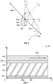
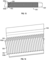
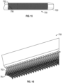
- FIGS 11-16 illustrate views of embodiments of traction assemblies 550, 650, 750 which can be formed along inner portions of the earstems, such as right earstems 520, 620, 720.
- the traction assemblies can include extensions, such as horizontal extensions 552 which extend horizontally along a length of the right earstem 520, vertical extensions 652 which extend vertically along the right earstem 620, and rod extensions 752 which have a rod-like shape, which extend from a surface of the earstem.
- These extensions can include tips 554, 654, 754 which can include traction surfaces such as those described herein.
- the use of extensions can be beneficial in reducing the likelihood that the traction surfaces contact a user's hair.
- the extensions such as extensions 552, 652, 752 can be sized and shaped such that they extend past a user's hair and allow tips, such as tips 554, 654, 754, to contact a user's scalp.
- the extensions can include a curvature such as that illustrated in connection with extensions 652 wherein a middle portion 656 of the extensions 652 extend further in a posterior direction than the ends 658a, 658b of the extensions.
- Such curvature is also illustrated in connection with extensions 752 in which the extensions are offset 752 such that extensions 752 along a middle portion, such as extension 756, are positioned further posteriorly than extensions 752 along the ends.
- the extensions can project outwardly at an angle such as that illustrated in connection with extensions 652,752.
- the portions of the eyewear positioned adjacent or proximate a user's hair can have traction surfaces along portions of the earstem which are less likely to contact a user's hair but would still contact a user's ear.
- the traction surfaces can be positioned along a bottom and/or outwardly facing portion of the earstem.
- the term “about,” “approximately,” or “generally,” means that quantities, dimensions, sizes, formulations, parameters, shapes and other characteristics need not be exact, but may be approximated and/or larger or smaller, as desired, reflecting acceptable tolerances, conversion factors, rounding off, measurement error and the like and other factors known to those of skill in the art. For example, in some embodiments, the terms “about”, “approximately”, or “generally”, may be within 20% of the stated value.
- the term “substantially” means that the recited characteristic, parameter, or value need not be achieved exactly, but that deviations or variations, including for example, tolerances, measurement error, measurement accuracy limitations and other factors known to those of skill in the art, may occur in amounts that do not preclude the effect the characteristic was intended to provide. For example, in some embodiments, the terms “substantially” may be within 5% of the stated value.
Landscapes
- Physics & Mathematics (AREA)
- Health & Medical Sciences (AREA)
- General Physics & Mathematics (AREA)
- Ophthalmology & Optometry (AREA)
- Optics & Photonics (AREA)
- Eyeglasses (AREA)
Claims (10)
- Brille (100, 200, 300, 400), umfassend:
eine Stütze (110, 210, 310, 410), die dazu konfiguriert ist, an einem Kopf eines Benutzers getragen zu werden, und dazu konfiguriert ist, eine Linse (160, 260, 360, 462, 464) in einem Sichtfeld eines Benutzers zu stützen, wobei die Stütze Folgendes umfasst:einen Ohrbügel (120, 130, 220, 230, 320, 330, 420, 430), der eine Außenfläche umfasst, die dazu konfiguriert ist, während der Verwendung in der Nähe einer lateralen Seite eines Kopfes eines Benutzers und eines Ohrs eines Benutzers positioniert zu sein; undein Nasenstück (146, 246a, 246b, 346, 446), das eine Außenfläche umfasst, die dazu konfiguriert ist, während der Verwendung in der Nähe einer Nase eines Benutzers positioniert zu sein; undeine Traktionsfläche (150, 250a-c, 350a-c, 450c) an mindestens einem des Ohrbügels und des Nasenstücks, wobei die Traktionsfläche dazu konfiguriert ist, eine Traktionskraft auf eine Kontaktfläche (484, 492) an einer Vielzahl von Kontaktpunkten innerhalb der Kontaktfläche auszuüben, wobei die Traktionskraft dazu konfiguriert ist, ein Rutschen der Brille an einem Kopf eines Benutzers zu verhindern, wenn sie getragen wird, wobei an einem Kontaktpunkt innerhalb der Kontaktfläche die Traktionsfläche derart konfiguriert ist, dass:wenn sie einer Kraft in einer ersten Richtung innerhalb einer Ebene ausgesetzt ist, die die Kontaktfläche an dem Kontaktpunkt tangiert, die Traktionsfläche bis zu einem ersten Betrag an Traktionskraft ausüben kann, bevor sie rutscht, undwenn sie einer Kraft in einer zweiten Richtung innerhalb der Ebene ausgesetzt ist, die die Kontaktfläche an dem Kontaktpunkt tangiert, die Traktionsfläche bis zu einem zweiten Betrag an Traktionskraft ausüben kann, bevor sie rutscht,wobei der erste Betrag an Traktionskraft, wenn sie der Kraft in der ersten Richtung ausgesetzt ist, größer ist als der zweite Betrag an Traktionskraft, wenn sie der Kraft in der zweiten Richtung ausgesetzt ist,wobei die Traktionsfläche eine Vielzahl von Vorsprüngen (454) im Mikrobereich oder Nanobereich umfasst, die sich schräg von der Außenfläche (455) erstreckt, an der sich die Traktionsfläche befindet, und dadurch gekennzeichnet, dass die Traktionsfläche einstückig an der Stütze ausgebildet ist. - Brille nach Anspruch 1, wobei:sich die Traktionsfläche mindestens an dem Nasenstück befindet und die Kontaktfläche mindestens ein Abschnitt der Nase des Benutzers ist; undsich an einem oder mehreren Kontaktpunkten innerhalb der Kontaktfläche die erste Richtung im Allgemeinen nach unten und anterior relativ zu der Nase des Benutzers erstreckt und mit einer ersten Achse einen spitzen Winkel ausbildet, wobei die erste Achse innerhalb der Ebene liegt, die die Kontaktfläche an dem einen oder den mehreren Kontaktpunkten tangiert, und parallel zu einer horizontalen Achse ist.
- Brille nach Anspruch 1, wobei:sich die Traktionsfläche mindestens an dem Ohrbügel befindet und die Kontaktfläche mindestens ein Abschnitt des Ohrs des Benutzers ist; undsich an einem oder mehreren Kontaktpunkten innerhalb der Kontaktfläche die erste Richtung im Allgemeinen anterior relativ zu einem Ohr eines Benutzers erstreckt.
- Brille nach Anspruch 1, wobei sich die Traktionsfläche sowohl an dem Ohrbügel als auch an dem Nasenstück befindet.
- Brille nach Anspruch 1, wobei sich die Vielzahl von Vorsprüngen, die sich schräg von der Außenfläche erstreckt, in einer Richtung mit einer Komponente erstreckt, die im Allgemeinen der ersten Richtung entgegengesetzt ist.
- Brille nach Anspruch 1, wobei die Vielzahl von Vorsprüngen, die sich schräg von der Außenfläche erstreckt, mehr parallel zu der Außenfläche als senkrecht ist.
- Brille nach Anspruch 1, wobei die Vielzahl von Vorsprüngen, die sich schräg von der Außenfläche erstreckt, mehr senkrecht zu der Außenfläche als parallel ist.
- Brille nach Anspruch 1, wobei die Vielzahl von Vorsprüngen, die sich schräg von der Außenfläche erstreckt, im Allgemeinen gleichermaßen senkrecht zu der Außenfläche wie parallel ist.
- Brille nach Anspruch 1, wobei die Traktionsfläche aus dem gleichen Material wie das Material der Abschnitte der Stütze benachbart zu der Traktionsfläche ausgebildet ist.
- Brille nach einem der vorhergehenden Ansprüche, wobei sich die Traktionsfläche mindestens an dem Nasenstück befindet, wobei die Kontaktfläche mindestens ein Abschnitt der Nase des Benutzers ist, wobei die Traktionskraft dazu konfiguriert ist, ein Rutschen der Brille an dem Kopf des Benutzers zu verhindern, wenn sie getragen wird, wobei sich an einem Kontaktpunkt innerhalb der Kontaktfläche die erste Richtung im Allgemeinen nach unten und anterior relativ zu der Nase des Benutzers erstreckt und mit einer ersten Achse einen spitzen Winkel ausbildet, wobei die erste Achse innerhalb der Ebene liegt, die die Kontaktfläche an dem einen oder den mehreren Kontaktpunkten tangiert, und parallel zu einer horizontalen Achse ist.
Applications Claiming Priority (2)
| Application Number | Priority Date | Filing Date | Title |
|---|---|---|---|
| US201562264424P | 2015-12-08 | 2015-12-08 | |
| PCT/US2016/065631 WO2017100456A1 (en) | 2015-12-08 | 2016-12-08 | Eyewear traction devices and methods |
Publications (3)
| Publication Number | Publication Date |
|---|---|
| EP3387485A1 EP3387485A1 (de) | 2018-10-17 |
| EP3387485A4 EP3387485A4 (de) | 2019-08-28 |
| EP3387485B1 true EP3387485B1 (de) | 2025-05-07 |
Family
ID=58800345
Family Applications (1)
| Application Number | Title | Priority Date | Filing Date |
|---|---|---|---|
| EP16873847.4A Active EP3387485B1 (de) | 2015-12-08 | 2016-12-08 | Vorrichtungen und verfahren zum ziehen von brillen |
Country Status (5)
| Country | Link |
|---|---|
| US (1) | US10156734B2 (de) |
| EP (1) | EP3387485B1 (de) |
| JP (1) | JP2018538575A (de) |
| CN (1) | CN209433137U (de) |
| WO (1) | WO2017100456A1 (de) |
Families Citing this family (6)
| Publication number | Priority date | Publication date | Assignee | Title |
|---|---|---|---|---|
| AU2013308734B2 (en) | 2012-08-31 | 2016-07-21 | Oakley, Inc. | Eyewear having multiple ventilation states |
| AU2015235947B2 (en) | 2014-03-27 | 2017-12-07 | Oakley, Inc. | Mounting mechanism for eyewear |
| WO2017062813A1 (en) | 2015-10-09 | 2017-04-13 | Oakley, Inc. | Headworn supports with passive venting and removable lens |
| US10359642B2 (en) | 2016-04-22 | 2019-07-23 | Oakley, Inc. | Mounting mechanism for eyewear |
| US10809545B2 (en) | 2017-04-14 | 2020-10-20 | Oakley, Inc. | Headworn supports having dynamic venting systems |
| US12189213B2 (en) * | 2021-07-12 | 2025-01-07 | Tyr Sport, Inc. | Eyewear with offset temple and nose grips |
Family Cites Families (427)
| Publication number | Priority date | Publication date | Assignee | Title |
|---|---|---|---|---|
| US1308477A (en) | 1919-07-01 | William m | ||
| US245268A (en) | 1881-08-09 | Frame for eyeglasses | ||
| US1206457A (en) | 1916-06-03 | 1916-11-28 | Silas B Mills | Spectacles or other vision-glasses. |
| US1588775A (en) | 1924-07-30 | 1926-06-15 | American Optical Corp | Eye protector |
| US1943910A (en) | 1927-06-15 | 1934-01-16 | American Optical Corp | Goggles |
| US1942393A (en) | 1927-06-15 | 1934-01-09 | American Optical Corp | Aviator's goggles |
| US1839386A (en) | 1927-07-11 | 1932-01-05 | Fischer Charles | Goggles |
| US1918954A (en) | 1927-10-18 | 1933-07-18 | American Optical Corp | Goggle |
| US1910456A (en) | 1929-05-02 | 1933-05-23 | American Optical Corp | Goggles |
| US2098512A (en) | 1933-08-01 | 1937-11-09 | Bay State Optical Co | Eyeglass construction |
| US2042400A (en) | 1934-08-14 | 1936-05-26 | Victor R Hon | Optical clasp |
| GB468443A (en) * | 1936-01-03 | 1937-07-05 | Frank Layton Grier | Improvements in or relating to nose pads for eyeglasses |
| GB512419A (en) | 1938-02-01 | 1939-09-15 | Twinco Ltd | Improvements in or relating to the manufacture of spectacles and goggles |
| US2391361A (en) | 1943-09-11 | 1945-12-18 | Watchemoket Optical Co Inc | Goggle |
| US2504157A (en) | 1943-09-23 | 1950-04-18 | Lapin Products Inc | Molded plastic sunglasses and the like |
| US2443422A (en) | 1945-07-03 | 1948-06-15 | Julius E Hansen | Goggles |
| US2571704A (en) | 1948-09-17 | 1951-10-16 | American Optical Corp | Ophthalmic mounting |
| US2556847A (en) | 1949-05-27 | 1951-06-12 | Anglo Iranian Oil Co Ltd | Eyeshield |
| US2610323A (en) | 1950-07-28 | 1952-09-16 | American Optical Corp | Fage protective device |
| US2671379A (en) | 1950-08-23 | 1954-03-09 | Polaroid Corp | Ophthalmic mounting |
| US2652746A (en) | 1950-12-11 | 1953-09-22 | Shanks Robert Randolph | Eyeglasses frame with detachably mounted lenses |
| US2799862A (en) | 1954-07-19 | 1957-07-23 | American Optical Corp | Eye protective means |
| FR1126329A (fr) | 1955-06-21 | 1956-11-20 | Dolomit | Monture de lunettes pour le soleil et pour la vue |
| US3084595A (en) | 1960-01-11 | 1963-04-09 | Leon W Watts | Frame for eyeglasses |
| FR1290346A (fr) | 1961-03-03 | 1962-04-13 | Perfectionnements aux montures de lunettes | |
| US3214767A (en) | 1962-12-20 | 1965-11-02 | Chicago Eye Shield Company | Face shield |
| US3229303A (en) | 1963-07-16 | 1966-01-18 | Renauld International Inc | Sportsman's goggle |
| US3233250A (en) | 1963-07-16 | 1966-02-08 | Renauld International Inc | Ski shield |
| US3395964A (en) | 1964-04-03 | 1968-08-06 | Rene Nieder Dit Chartrice | Spectacle mounting with biased nose bridge and temple pieces |
| US3383707A (en) | 1966-05-03 | 1968-05-21 | Bachmann Bros Inc | Flip-up sunglass construction |
| US3552840A (en) | 1968-09-16 | 1971-01-05 | Lorna R Braget | Eyeglass frame construction for removable lenses |
| FR2088866A5 (de) | 1970-04-28 | 1972-01-07 | Plastinax | |
| US3659931A (en) | 1970-08-03 | 1972-05-02 | Philip J Allen | Eye glass lens adjuster |
| US3826564A (en) | 1970-11-02 | 1974-07-30 | Spector G | Eye glass frame for replaceable lenses |
| US3691565A (en) | 1970-11-25 | 1972-09-19 | Omnitech Inc | Flight deck goggle |
| US3829201A (en) | 1973-06-28 | 1974-08-13 | Hilsinger Corp | Cushioning mount for a lens in the rim of an ophthalmic mounting |
| US3931646A (en) | 1974-06-26 | 1976-01-13 | American Optical Corporation | Double lens goggle |
| US3901589A (en) | 1974-07-08 | 1975-08-26 | American Cyanamid Co | Clip-on flip-up goggles |
| JPS5144345U (de) * | 1974-09-28 | 1976-04-01 | ||
| US4331393A (en) | 1974-11-21 | 1982-05-25 | Bradley Jr James B | Ophthalmic fitting set and method |
| IT1033888B (it) | 1975-05-26 | 1979-08-10 | Ottica Snc | Sistema di fissaggio a facile intercambiabilita per lenti da occhiale e relativi occhiali da nuoto per uso sportivo in genere e maschere subacquee |
| US4023214A (en) | 1976-05-17 | 1977-05-17 | Arthur Waldherr | Means for holding eyeglasses within a scuba mask |
| DE7717685U1 (de) | 1977-06-03 | 1977-10-13 | Carrera Herstellung Und Vertrieb Von Sportbrillen Und Sportartikeln Gmbh, 8013 Haar | Schutzbrille, insbesondere sonnenschutzbrille mit metallfassung |
| US4153347A (en) | 1977-06-08 | 1979-05-08 | Myer C Randolph | Eyeglass frames with removable, interchangeable lenses, rims and temple pieces |
| US4178080A (en) | 1977-08-30 | 1979-12-11 | Elder Eugene E | Adjustable nose piece assembly for eyeglasses |
| US4264987A (en) | 1978-11-02 | 1981-05-05 | Runckel John L | Goggles |
| FR2447819A1 (fr) | 1979-01-30 | 1980-08-29 | Essilor Int | Procede et dispositif pour la decoration d'un quelconque substrat, en particulier monture de lunettes |
| GB2055222B (en) * | 1979-03-01 | 1982-09-22 | Donovan L B | Spectacles |
| US4340282A (en) | 1979-10-13 | 1982-07-20 | Mamoru Murakami | Lens securing device |
| DE2941961A1 (de) | 1979-10-17 | 1981-04-30 | Krautkrämer GmbH, 5000 Köln | Verfahren zur signalspannungsabhaengigen veraenderung des verstaerkungsfaktors |
| US4357080A (en) | 1980-02-25 | 1982-11-02 | Sol-Optics, Inc. | Eyeglass frame having removable lens |
| US4304469A (en) | 1980-02-25 | 1981-12-08 | Solomon Charles I | Eyeglass frame having removable lenses |
| JPS56126611A (en) | 1980-03-12 | 1981-10-03 | Hanken Seisakusho:Kk | Muffler |
| JPS57176119U (de) | 1981-04-28 | 1982-11-08 | ||
| JPS5979827A (ja) | 1982-10-29 | 1984-05-09 | Hitachi Micro Comput Eng Ltd | エンジンのノツク検出方式 |
| JPS59104127A (ja) | 1982-12-07 | 1984-06-15 | Nippon Telegr & Teleph Corp <Ntt> | 微細パタ−ン形成方法 |
| JPS59104127U (ja) | 1982-12-27 | 1984-07-13 | 桜井 末広 | 眼鏡枠 |
| US4527291A (en) | 1983-02-01 | 1985-07-09 | Uvex Winter Optik Gmbh | Safety goggles, in particular for work use |
| US4515448A (en) | 1983-03-28 | 1985-05-07 | Oakley, Inc. | Sunglasses |
| US4670084A (en) | 1983-06-20 | 1987-06-02 | David Durand | Apparatus for applying a dye image to a member |
| US4471496A (en) | 1983-06-27 | 1984-09-18 | Cabot Corporation | Articulated earmuff-to-headband attachment construction |
| JPS6094624U (ja) | 1983-12-01 | 1985-06-27 | 有限会社アイ・プローター小林 | 眼鏡枠 |
| FR2556851B1 (fr) | 1983-12-19 | 1986-05-02 | Essilor Int | Structure porteuse pour monture de lunettes et face destine a lui etre adapte |
| JPS60143420U (ja) | 1984-03-02 | 1985-09-24 | 長谷川眼鏡株式会社 | レンズ交換式メガネのストツパ−構造 |
| US4662966A (en) | 1984-09-26 | 1987-05-05 | Nissha Printing Co. Ltd. | Apparatus for transfer printing |
| US4616367A (en) | 1984-11-14 | 1986-10-14 | Jean Jr Joseph A | Headband with detachable lenses |
| US4867550A (en) | 1985-01-11 | 1989-09-19 | Oakley, Inc. | Toroidal lens for sunglasses |
| US4730915A (en) | 1985-01-11 | 1988-03-15 | Oakley, Inc. | Detachable component sunglasses |
| US4859048A (en) | 1985-01-11 | 1989-08-22 | Oakley, Inc. | Cylindrical lens for sunglasses |
| US4674851A (en) | 1985-01-11 | 1987-06-23 | Jannard James H | Removable multi-component sunglasses |
| JPH0214018Y2 (de) | 1985-03-25 | 1990-04-17 | ||
| US4662729A (en) * | 1985-04-18 | 1987-05-05 | Dobson Johnnie M D | Clip-on cuffs for eyeglass temples |
| US4747681A (en) * | 1985-05-20 | 1988-05-31 | Brower Arthur B | Traction strip for eyewear |
| DE8524634U1 (de) | 1985-08-28 | 1985-10-17 | Optyl Holding GmbH & Co Verwaltungs-KG, 8013 Haar | Brille mit auswechselbaren Sichtscheiben |
| GB2181859A (en) | 1985-09-27 | 1987-04-29 | Morris Goldschmidt | Spectacles with manually replaceable lenses |
| US4686712A (en) | 1986-09-11 | 1987-08-18 | Spiva Lowell E | Goggle mounting system |
| GB2199155A (en) | 1986-09-22 | 1988-06-29 | Morris Goldschmidt | Spectacles with manually replaceable lenses having split rims |
| US4715702A (en) | 1986-10-20 | 1987-12-29 | Dillon Stephen M | Decorative lens |
| US4822158A (en) | 1987-06-30 | 1989-04-18 | Optyl Eyewear Fashion International Corporation | Eyeglasses with removable lens assembly |
| US5048944A (en) | 1987-06-30 | 1991-09-17 | Optyl Eyewear Fashion International Corporation | Eyeglasses with removable lens assembly |
| US4983030A (en) | 1987-10-08 | 1991-01-08 | Up To Date, Inc. | Retaining mechanism for eyeglasses having interchangeable lenses |
| US4813775A (en) | 1987-12-04 | 1989-03-21 | Kaksonen Pirjo M | Eyeglass frames |
| US4843655A (en) | 1987-12-15 | 1989-07-04 | Alpina Int'l Sport + Optik-Vertriebs-Gmbh | Protective goggles |
| US4901374A (en) | 1988-04-22 | 1990-02-20 | Prolens | Face shield |
| JPH0542419Y2 (de) | 1988-04-27 | 1993-10-26 | ||
| US4878749A (en) | 1988-06-29 | 1989-11-07 | Mcgee James E | Protective eyewear with interchangeable decorative frames |
| JPH0758892B2 (ja) | 1988-07-06 | 1995-06-21 | 三菱電機株式会社 | ディジタルパルス幅変調回路 |
| EP0353929A1 (de) | 1988-08-02 | 1990-02-07 | Hellberg Protection Ab | Brille |
| US5182587A (en) | 1988-11-18 | 1993-01-26 | Murai Co., Ltd. | Eyeglass frame having antirotation connection |
| FR2626682B1 (fr) | 1989-01-31 | 1992-12-31 | Mugnier Marc | Charnieres de positionnement adaptees aux montures de lunettes |
| JPH02240360A (ja) | 1989-03-14 | 1990-09-25 | Sekisui Chem Co Ltd | 軒先構造 |
| US5144344A (en) | 1989-05-25 | 1992-09-01 | Sony Corporation | Spectacles for stereoscopic pictures |
| US5191364A (en) | 1989-09-11 | 1993-03-02 | Kopfer Rudolph J | Protective eyewear for use in sports and the like |
| US4951322A (en) | 1989-09-27 | 1990-08-28 | Lin David J T | Detachable mono-glass sports goggles |
| IT1240243B (it) | 1990-01-26 | 1993-11-30 | Moda Solaris Spa | Struttura di occhiale da sole |
| US5007727A (en) | 1990-02-26 | 1991-04-16 | Alan Kahaney | Combination prescription lens and sunglasses assembly |
| US5056163A (en) | 1990-05-15 | 1991-10-15 | Chou Chih T | Sweat-absorbing strip for sport goggles |
| WO1992001560A1 (fr) | 1990-07-18 | 1992-02-06 | Nissha Printing Co., Ltd. | Dispositif et procede d'impression par transfert |
| US5016293A (en) | 1990-07-25 | 1991-05-21 | Brett Lickle | Air induction system for goggle |
| DE9012115U1 (de) | 1990-08-23 | 1990-10-25 | Uvex Winter Optik GmbH, 8510 Fürth | Schutz- bzw. Sportbrille, insbesondere Radbrille |
| US5208614A (en) | 1990-11-30 | 1993-05-04 | Oakley, Inc. | Concavely indented lenses for eyeware |
| AT397441B (de) | 1991-01-17 | 1994-04-25 | Silhouette Int Gmbh | Scharniergelenk zwischen bügel und bügelbacken eines brillengestells |
| AT398250B (de) | 1991-01-17 | 1994-10-25 | Silhouette Int Gmbh | Brillengestell |
| IT1247043B (it) | 1991-01-21 | 1994-12-12 | Moda Solaris Spa | Montatura per occhiali ad elementi scomponibili |
| DE4118018C1 (de) | 1991-06-01 | 1992-05-07 | Uvex Winter Optik Gmbh, 8510 Fuerth, De | |
| US5423092A (en) | 1991-08-23 | 1995-06-13 | Axe Co., Ltd. | Goggles and sunglasses |
| FR2681442B1 (fr) | 1991-09-18 | 1994-09-09 | Bolle Snc Ets | Nez selle interchangeable pour le montage de verres de lunettes sur une paire de lunettes de soleil. |
| FR2684046A1 (fr) | 1991-11-26 | 1993-05-28 | Claveau Jean Noel | Procede de decoration par sublimation. |
| FR2684292B1 (fr) | 1991-11-29 | 1997-06-20 | Cebe International Sa | Lunette-masque pour la protection des yeux. |
| US5387949A (en) | 1992-01-29 | 1995-02-07 | Oakley, Inc. | Eyeglass connection device |
| US5390369A (en) | 1992-05-11 | 1995-02-21 | Scorpion Sunglasses, Inc. | Multi-functional protective eyewear |
| DE9207109U1 (de) | 1992-05-26 | 1992-07-30 | Uvex Winter Optik GmbH, 8510 Fürth | Brille, insbesondere Arbeitsschutz- oder Sportbrille |
| US5379464A (en) | 1992-07-24 | 1995-01-10 | Schleger; Linda | Facial shield, particularly for protection from the sun |
| US5379463A (en) | 1992-07-24 | 1995-01-10 | Hubert Greenway | Facial shield, particularly for protection from the sun |
| FR2695486B1 (fr) | 1992-09-04 | 1994-11-18 | Essilor Int | Monture de lunettes. |
| FR2697921B1 (fr) | 1992-11-12 | 1997-03-28 | Mugnier Marc | Elément d'appui nasal formant sangle-coussin pour monture de lunettes. |
| US5291230A (en) | 1992-11-17 | 1994-03-01 | Bradley James B | Ophthalmic device includes a detachable nosepiece |
| US5373331A (en) | 1993-02-03 | 1994-12-13 | Vallalla; Rosalie G. | Eyeglass and lens interchange structure |
| US5410763A (en) | 1993-02-11 | 1995-05-02 | Etablissments Bolle | Eyeshield with detachable components |
| US5550599A (en) | 1994-01-10 | 1996-08-27 | Oakley, Inc. | Surface modified lens |
| NZ260250A (en) | 1993-05-25 | 1997-11-24 | James Henry Jannard | Lens system for eyeglasses; peripheral zone of lens has its surface modified by grooving |
| US5418581A (en) | 1993-06-07 | 1995-05-23 | Bausch & Lomb Incorporated | Hinge system for eyewear |
| JPH0732628A (ja) | 1993-07-26 | 1995-02-03 | Matsushita Electric Ind Co Ltd | 記録装置 |
| JPH0764028A (ja) | 1993-07-31 | 1995-03-10 | Seijin Sai | テンプル梃子型開閉レンズ交換式眼鏡枠アクセサリー |
| US5455639A (en) | 1993-10-29 | 1995-10-03 | Wgm Safety Corp. | Protective eyewear with replaceable lens |
| US5565589A (en) | 1993-11-03 | 1996-10-15 | Wisconsin Alumni Research Foundation | 17-formyl-5,6-trans-vitamin D compounds |
| US5467148A (en) | 1993-11-08 | 1995-11-14 | Bausch & Lomb Incorporated | Eyewear having interchangeable lenses |
| JPH07140423A (ja) | 1993-11-22 | 1995-06-02 | Aichi Steel Works Ltd | 眼 鏡 |
| US5752280A (en) | 1993-12-13 | 1998-05-19 | Itech Sport Products, Inc. | Eye protection device for headgear |
| US5428407A (en) | 1993-12-15 | 1995-06-27 | Crews Inc | Prescription lens attachable to safety glasses |
| JPH07234385A (ja) | 1994-02-21 | 1995-09-05 | Yasuhiro Okada | めがねフレーム |
| US5515116A (en) | 1994-03-22 | 1996-05-07 | Gargoyles, Inc. | Removable eyeglass nosebridge |
| US6098204A (en) | 1994-03-24 | 2000-08-08 | Arnette Optical Illusions, Inc. | Ski goggles for use with an insulating hood |
| US5418580A (en) | 1994-05-05 | 1995-05-23 | Larry L. Sondrol | Interchangeable lens eyeglasses with pivoting temple release mechanism |
| FR2721860B1 (fr) | 1994-06-30 | 1996-08-23 | Claveau Jean Noel | Dispositif permettant de sublimer un decor sur la surface d'un objet de forme quelconque |
| US5548841A (en) | 1994-07-25 | 1996-08-27 | Mfd Enterprises, Inc. | Headband magnifier |
| JPH0862544A (ja) | 1994-08-24 | 1996-03-08 | Yamaoka Kanagata Seisakusho:Kk | 組立て自在メガネ |
| DE4431328C2 (de) | 1994-09-02 | 1996-07-25 | Porsche Design Gmbh | Brille, insbesondere Sport- und/oder Freizeitbrille |
| US5619287A (en) | 1995-01-23 | 1997-04-08 | Tseng; Liang-Chin | Eyeglasses with a replaceable sunshade |
| US5493348A (en) | 1995-02-22 | 1996-02-20 | Crews, Inc. | Means for mounting a prescription lens accessory onto a pair of glasses |
| US5617588A (en) | 1995-03-16 | 1997-04-08 | Uvex Safety, Inc. | Snap together protective goggle construction with toric lens |
| US6929364B1 (en) | 1995-04-04 | 2005-08-16 | Oakley, Inc. | Contoured metal eyeglass frames |
| US5805261A (en) | 1995-04-04 | 1998-09-08 | Oakley, Inc. | Biased eyeglass frames |
| US5541674A (en) | 1995-04-04 | 1996-07-30 | Oakley, Inc. | Dimensionally Stable eyewear |
| US5708489A (en) | 1995-04-04 | 1998-01-13 | Oakley, Inc. | Articulated eyeglass frame |
| US5576775A (en) | 1995-06-09 | 1996-11-19 | Etablissements Bolle S.N.C. | Eyeglasses with controlled ventilation frame and lens |
| JP3021121U (ja) | 1995-07-29 | 1996-02-16 | 資生眼鏡株式会社 | メガネフレームのツル |
| US5685022A (en) | 1995-09-14 | 1997-11-11 | Essman; David W. | Renewable eye protective goggle assembly |
| US5657106A (en) | 1995-11-03 | 1997-08-12 | Crews, Inc. | Safety goggle assembly including corrective lenses |
| US5796461A (en) | 1995-11-22 | 1998-08-18 | Uvex Safety, Inc. | Protective eyeglass assembly |
| US5898468A (en) | 1995-11-28 | 1999-04-27 | Spy Optic, Inc. | Fog-resistant sunglasses incorporating ventilation channels |
| US5610668A (en) | 1995-11-28 | 1997-03-11 | Spy Optic, Inc. | Fog-resistant sunglasses incorporating ventilation channels |
| US5583583A (en) | 1995-11-29 | 1996-12-10 | Wilson; Ken | Metal frame sunglasses and method of making the same |
| WO1997021135A1 (en) | 1995-12-05 | 1997-06-12 | The Beta Group | Hinge connection for eyeglass frame |
| US5648832A (en) | 1995-12-05 | 1997-07-15 | Oakley, Inc. | Decentered noncorrective lens for eyewear |
| US5652954A (en) | 1995-12-21 | 1997-08-05 | Itech Sport Products Inc. | Pivotal eye protection shield for headgear |
| US5602603A (en) | 1995-12-22 | 1997-02-11 | Bondet; Pierre N. | Eyeglasses having interchangeable lenses and attachment clips |
| US5862529A (en) | 1996-01-23 | 1999-01-26 | Springuard Technology Group Inc | Device for protecting face and eyes against projectile impact |
| US5790230A (en) | 1996-02-16 | 1998-08-04 | Sved; Robert | Combination eyeglass assembly of sport or safety glasses with detachable prescription lenses |
| US5638145A (en) | 1996-02-29 | 1997-06-10 | Oakley, Inc. | Vented eyeglass lens |
| US5841506A (en) | 1996-05-08 | 1998-11-24 | Ozmix, Inc. | Superimposable eyeglasses |
| US5802622A (en) | 1996-05-09 | 1998-09-08 | Shalon Chemical Industries Ltd. | Protective goggles |
| US5765223A (en) | 1996-06-04 | 1998-06-16 | Mccausland; Mary L. | Face shield |
| JPH1039260A (ja) * | 1996-07-19 | 1998-02-13 | Akio Katayama | 眼鏡枠 |
| US6273564B1 (en) | 1996-08-07 | 2001-08-14 | David Wedeck | eyeglass frame for removal and insertion of lenses |
| US5914767A (en) | 1996-08-07 | 1999-06-22 | David Wedeck | Eyeglass frame adapted to removal and insertion of lenses |
| US5760866A (en) | 1996-08-07 | 1998-06-02 | David Wedeck | Eyeglass frame adapted to removal and insertion of lenses |
| US5929963A (en) | 1996-09-25 | 1999-07-27 | Smith Sport Optic, Inc. | Corrective lens system and support apparatus for use with protective eyewear devices |
| US5793463A (en) | 1996-12-16 | 1998-08-11 | Pareto Corporation | Universal attachment with moveable sideshields for eyeglasses |
| US5809580A (en) | 1996-12-20 | 1998-09-22 | Bausch & Lomb Incorporated | Multi-sport goggle with interchangeable strap and tear-off lens system |
| US6056399A (en) | 1997-01-29 | 2000-05-02 | Oakley, Inc. | Interchangeable nosepiece system |
| DE59710506D1 (de) | 1997-02-26 | 2003-09-04 | Alexander Grendelmeier | Brille mit aufsetzbarem Schutzschild |
| USD428620S (en) | 1997-05-19 | 2000-07-25 | Thawatchai Maturaporn | Eye shield |
| IT1293363B1 (it) | 1997-05-29 | 1999-02-25 | Killer Loop Eyewear Srl | Dispositivo di interconnessione, particolarmente per occhiali |
| US5956116A (en) | 1997-05-30 | 1999-09-21 | Eiko Ishiyama | Frame for eyeglasses |
| US5815235A (en) | 1997-07-09 | 1998-09-29 | John L. Runckel Trust | Ski goggles with pivotal frame members for interchanging lenses |
| TW352834U (en) | 1997-10-08 | 1999-02-11 | Mao Lin Entpr Co Ltd | Lens of sun glasses and buckle structure of frame |
| DE69711098T2 (de) | 1997-10-13 | 2002-11-07 | Bline Optic S.R.L., Pederobba | Befestigungsvorrichtung für brillengläser |
| US6105177A (en) | 1997-12-26 | 2000-08-22 | Paulson Manufacturing Corp. | Protective goggles |
| US6102033A (en) | 1998-03-10 | 2000-08-15 | 3M Innovative Properties Company | Attachment system for replacement helmet respirator lens |
| TW351459U (en) | 1998-03-16 | 1999-01-21 | Shiou-Wen Chiou | Novel glasses with replaceable lens |
| DK63198A (da) | 1998-05-07 | 1999-11-08 | Lindberg Optic Design As | Forhænger samt kombination af forhænger og brille |
| US5898469A (en) | 1998-05-20 | 1999-04-27 | Chiang Heng Trading Co., Ltd. | Mono-lens eyeglasses |
| AU4558299A (en) | 1998-06-12 | 1999-12-30 | Bausch & Lomb Incorporated | Eyewear with replaceable lens system |
| US6009564A (en) | 1998-06-24 | 2000-01-04 | Oakley, Inc. | Optically corrected goggle |
| US6094751A (en) | 1998-07-13 | 2000-08-01 | John R. Gregory | Goggle with replaceable seal |
| US6047410A (en) | 1998-08-03 | 2000-04-11 | Eye Safety Systems, Inc. | Goggle frame and attachment system |
| US6062688A (en) | 1998-08-04 | 2000-05-16 | Vinas; Joseph F. | Detachable eyeglass foam shield |
| AT407306B (de) | 1998-08-31 | 2001-02-26 | Silhouette Internat Schmied Gm | Formschlüssige verbindung zwischen einem metallischen steg und einem aus kunststoff gespritzten formkörper, insbesondere für eine brille |
| AT406529B (de) | 1998-10-12 | 2000-06-26 | Silhouette Int Schmied Ag | Inklinationsgelenk für einen brillenbügel |
| US5971538A (en) | 1998-10-30 | 1999-10-26 | Hewlett-Packard Company | Articulated nose bridge for head mounted display |
| US6119279A (en) | 1999-01-07 | 2000-09-19 | Sharp Plastics Manufacturing Ltd. | Swim goggles with twistable nosebridge |
| US6007199A (en) | 1999-02-02 | 1999-12-28 | Yang; Tien | Eyeglasses with detachable bows |
| US6086199A (en) | 1999-03-03 | 2000-07-11 | Nike, Inc. | Eyewear with removable lenses and method of removably mounting lenses in eyewear |
| US6244705B1 (en) | 1999-06-28 | 2001-06-12 | Donald L. Ledbetter | Auxiliary corrective eyeglasses for use with primary eyeglasses |
| US6282727B1 (en) | 1999-07-13 | 2001-09-04 | Arthur Charles Lindahl | Sports eye wear with detachable goggle members |
| US6938277B2 (en) | 1999-07-13 | 2005-09-06 | Arthur Charles Lindahl | Removable eyewear member |
| FR2800173B1 (fr) | 1999-10-21 | 2003-06-13 | Royal Plastic | Monture de lunettes et lunettes pourvues d'une telle monture |
| US6375321B1 (en) | 1999-10-23 | 2002-04-23 | Suk Jae Lee | Method and device for coupling spectacles and clip-on sunshades with each other |
| KR200175839Y1 (ko) | 1999-10-23 | 2000-03-15 | 이석재 | 안경과 클립의 결합구조 |
| US6193367B1 (en) | 2000-03-01 | 2001-02-27 | Jannack Corporation | Quick release glasses lens |
| US6231181B1 (en) | 2000-03-23 | 2001-05-15 | Qr Spex, Inc. | Exchangeable eyeglass temple pieces utilizing quick-connect attachment |
| US6290354B1 (en) | 2000-04-04 | 2001-09-18 | G Safran Corp. | Corrective eyewear attachment and method |
| US20020039928A1 (en) | 2000-04-10 | 2002-04-04 | Spurgeon Stephen L. | Decorative bowling ball and method therefor |
| US6224209B1 (en) | 2000-04-25 | 2001-05-01 | Wu Meihua Chen | Eyeglasses frame allowing replacement of lenses |
| US6502937B2 (en) | 2000-05-03 | 2003-01-07 | Stanley Schleger | Eyewear with prescription lens inserts |
| US6206519B1 (en) | 2000-05-08 | 2001-03-27 | Mao Lin Enterprise Co., Ltd. | Eyeglasses assembly including a removable auxiliary eyeglasses unit |
| US6233342B1 (en) | 2000-06-29 | 2001-05-15 | Pan-Optx, Inc. | Sunglasses with adjustable ventilation |
| JP2002040377A (ja) | 2000-07-28 | 2002-02-06 | Seiji Fukai | 眼鏡フレーム |
| US6276794B1 (en) | 2000-08-31 | 2001-08-21 | Herman Chiang | Swimming goggles |
| US6477717B1 (en) | 2000-10-10 | 2002-11-12 | Q.D.S. Injection Molding, Inc. | Swim mask having virtual buckle pivot point |
| FR2815727B1 (fr) | 2000-10-25 | 2003-03-07 | Lebas Sports | Paire de lunettes a verres interchangeables |
| EP1348991B1 (de) | 2000-12-27 | 2008-03-12 | Madmix Japan Co. Ltd | Brillen mit windabschirmung, windabschirmung für brillen und verfahren zur windabschirmung in brillen |
| JP2002228986A (ja) | 2001-02-02 | 2002-08-14 | Hasegawa Gankyo Kk | ワンタッチレンズ着脱メガネ |
| US6386704B1 (en) | 2001-02-09 | 2002-05-14 | Huei-Min Wu | Sunglasses |
| US6994434B2 (en) | 2001-02-23 | 2006-02-07 | Cabot Safety Intermediate Corp. | Eyewear with lens hinge |
| CA2337731C (en) | 2001-02-23 | 2008-01-15 | Leader Industries Inc. | Eyewear |
| US6908193B2 (en) | 2001-02-23 | 2005-06-21 | Cabot Safety Intermediate Corporation | Eyewear |
| US6386703B1 (en) | 2001-03-02 | 2002-05-14 | Jih-Hsing Huang | Sunglasses combinable easily and quickly with a pair of near-sight eyeglasses |
| EP1377402A4 (de) | 2001-03-14 | 2007-12-26 | Key Tech Inc | Verfahren und vorrichtung zum drucken eines farbbildes auf ein dreidimensionales objekt |
| USD452522S1 (en) | 2001-03-19 | 2001-12-25 | Grace Chiou | Frame of eyeglasses |
| US6564804B2 (en) | 2001-03-26 | 2003-05-20 | Robert G. Salatka | Face shield and face shield support assembly |
| TWI270478B (en) | 2001-03-29 | 2007-01-11 | Fresco Plastics | Method and apparatus for continuously forming dye sublimation images in solid substrates |
| US7003802B2 (en) | 2001-04-23 | 2006-02-28 | Jt Usa, Llc | Face mask with detachable eye shield |
| US7039959B2 (en) | 2001-04-30 | 2006-05-09 | John Dondero | Goggle for protecting eyes with movable single-eye lenses and methods for using the goggle |
| US6718561B2 (en) | 2001-04-30 | 2004-04-13 | John Dondero | Goggle for protecting eyes with a movable lens and methods for using the goggle |
| ITTO20010413A1 (it) | 2001-05-03 | 2002-11-03 | Nico S R L | Occhiali con lenti intercambiabili. |
| US7091634B2 (en) | 2001-07-26 | 2006-08-15 | Kbc America, Inc. | Half-jacket eyewear with removable dust shield |
| US6926403B2 (en) | 2001-07-26 | 2005-08-09 | Kbc America, Inc. | Half-jacket eyewear with removable dust shield |
| KR200250343Y1 (ko) | 2001-07-26 | 2001-11-22 | 주식회사 티. 아이. 비 | 레저용 선글라스 |
| FR2828386B1 (fr) | 2001-08-10 | 2004-06-11 | Jean Noel Acquaviva | Ecran de vision coupe-vent |
| US6641263B2 (en) | 2001-08-14 | 2003-11-04 | Joel William Olney | Sunglasses with removable sealing member |
| US6428165B1 (en) | 2001-09-07 | 2002-08-06 | John C. Rivera | Interchangeable lens eyeglass system with interchangeable nosepiece |
| KR200259088Y1 (ko) | 2001-09-19 | 2001-12-31 | 문원일 | 마그네틱클립을 이용한 보조안경 체결구조 |
| US6575570B2 (en) | 2001-10-05 | 2003-06-10 | M.M. Evolution S.R.L. | Spectacle frame |
| DE10151464A1 (de) | 2001-10-18 | 2003-05-08 | Eye Systems Gmbh Chur | Anordnung mit einer Backe, einem Bügelkopfstück und einem Gelenk für eine Brille |
| US6550914B1 (en) | 2001-10-26 | 2003-04-22 | Pan-Optx, Inc. | Eyewear with filtered ventilation |
| US7200875B2 (en) | 2001-11-06 | 2007-04-10 | John Dondero | Goggle for protecting eyes with movable lenses and methods for making and using the goggle |
| US6732383B2 (en) | 2001-12-03 | 2004-05-11 | The Burton Corporation | Goggle with side arm for wearing with a helmet |
| US6826785B2 (en) | 2002-01-09 | 2004-12-07 | Smith Sport Optics, Inc. | Pivotable strap-buckle assembly |
| US6804835B2 (en) | 2002-01-25 | 2004-10-19 | Terry Chou | Lens/frame assembly for swimming goggles |
| US6732382B2 (en) | 2002-04-03 | 2004-05-11 | John Dondero | Goggle for protecting eyes with a movable vent cover and methods for using |
| US6561647B1 (en) | 2002-04-25 | 2003-05-13 | High Rainbow Ent. Co., Ltd. | One-piece lens and frame assembly |
| US7390086B2 (en) | 2002-05-24 | 2008-06-24 | Lee Jung I | Clip on eyeware with insertable member |
| US6702439B1 (en) | 2002-08-22 | 2004-03-09 | Jung I. Lee | Clip on eyeware with spring hinge |
| FR2842614B1 (fr) | 2002-07-17 | 2004-12-10 | Architectures | Monture de lunettes du type a liens de cerclage souples |
| US6533412B1 (en) | 2002-07-22 | 2003-03-18 | Navajo Manufacturing Company, Inc. | Interchangeable eyeglass lens system and method |
| US6637877B1 (en) | 2002-08-09 | 2003-10-28 | Gentex Corporation | Eyewear for ballistic and light protection |
| US6923537B2 (en) | 2002-08-09 | 2005-08-02 | Gentex Corporation | Eyewear for ballistic and light protection |
| US6729723B2 (en) | 2002-08-12 | 2004-05-04 | Yiling Xie | Spectacles set with detachable magnetic shelter frame |
| US6715157B2 (en) | 2002-08-20 | 2004-04-06 | Spy Optic, Inc. | Sports goggles |
| US7244022B2 (en) | 2002-08-22 | 2007-07-17 | Jung I. Lee | Clip on eyeware with spring hinge |
| US6742891B2 (en) | 2002-09-19 | 2004-06-01 | High Rainbow Ent. Co., Ltd. | Coupling system for securing a one-piece lens to temples |
| US6948813B2 (en) | 2003-01-21 | 2005-09-27 | Dye Precision, Inc. | Lens assembly parts and assemblies therefrom |
| US6854845B1 (en) | 2003-02-07 | 2005-02-15 | Donna Goldman | Eyeglasses with retention clip |
| AU2003213488A1 (en) | 2003-02-19 | 2004-09-09 | Jonathan Sceats Eyewear Pty. Limited | Eyewear with Interchangable Temples |
| AU2003901272A0 (en) | 2003-03-19 | 2003-04-03 | Martin Hogan Pty Ltd | Improvements in or relating to eyewear attachments |
| US7137700B2 (en) | 2003-03-20 | 2006-11-21 | Liberty Sport, Inc. | Impact resistant eyewear frame assembly having a split frame and fastener reinforcement |
| USD485570S1 (en) | 2003-04-28 | 2004-01-20 | Irene Corporation | Eyeglasses |
| US6712465B1 (en) | 2003-04-30 | 2004-03-30 | Irene Corporation | Eyeglasses having additional, replaceable lenses |
| ITBO20030283A1 (it) | 2003-05-08 | 2004-11-09 | Type 20 S R L | Occhiale a struttura alleggerita e procedimento di realizzazione del medesimo. |
| US6969171B2 (en) | 2003-06-25 | 2005-11-29 | Dioptics Medical Products, Inc. | Light-blocking air vents for eyewear |
| ATE370842T1 (de) | 2003-06-26 | 2007-09-15 | Key Tech Inc | Verfahren zum thermischen drucken eines farbstoffbildes auf ein dreidimensionales objekt durch verwendung flexibler heizelemente |
| US20060203188A1 (en) | 2003-08-06 | 2006-09-14 | Zelman Gary M | Eyeglasses having magnetically coupled primary lens frame and auxiliary lens frame |
| US6742890B1 (en) | 2003-08-26 | 2004-06-01 | Megasafe Products, Inc. | Mounting structure for lenses and a frame of an eyeglasses |
| JP4296061B2 (ja) | 2003-08-27 | 2009-07-15 | 株式会社イノアックコーポレーション | コンソールボックス |
| US6749299B1 (en) | 2003-09-03 | 2004-06-15 | Sun Sight Glasses Co., Ltd. | Auxiliary frame for eyeglasses |
| ITMI20030411U1 (it) | 2003-09-12 | 2005-03-13 | Opticos Srl | Sistema di visiere anti-condensa |
| US6857738B1 (en) | 2003-09-17 | 2005-02-22 | Nelson David Bove | Spectacles |
| CA2483484A1 (en) | 2003-10-02 | 2005-04-02 | Fujiuchi Toshiro | Interchangeable eyewear assembly |
| US7370961B2 (en) | 2003-10-02 | 2008-05-13 | Ira Lerner | Interchangeable eyewear assembly |
| US6953247B1 (en) | 2003-10-03 | 2005-10-11 | Duffy Charles J | Dive mask system |
| US7181779B2 (en) | 2004-01-23 | 2007-02-27 | K-2 Corporation | Sport goggle with side vent for improved ventilation |
| US8142015B2 (en) | 2003-10-28 | 2012-03-27 | Venetian Holdings, Llc. | Baby and toddler sunglasses |
| US6942338B2 (en) | 2003-11-03 | 2005-09-13 | Sun Hing Optical Manufactory Limited | Spectacle frame having user-replaceable arm |
| USD508255S1 (en) | 2003-11-24 | 2005-08-09 | Sun Sight Glasses Co., Ltd. | Eyeglass frame |
| US7237891B2 (en) | 2003-11-27 | 2007-07-03 | Kbc America, Inc. | Eyewear with removable shield |
| US7003811B2 (en) | 2003-12-03 | 2006-02-28 | Bacou-Dalloz Eye & Face Protection, Inc. | Detachable and rotatable clip |
| US6863395B1 (en) | 2003-12-29 | 2005-03-08 | Irene Corporation | Eyeglasses having detachable lenses |
| US6783235B1 (en) | 2004-01-21 | 2004-08-31 | Gazelle Corporation | Fog-free protective glasses |
| JP4441825B2 (ja) | 2004-01-29 | 2010-03-31 | 山本光学株式会社 | ゴーグル |
| US7267434B2 (en) | 2004-03-23 | 2007-09-11 | Dioptics Medical Products, Inc. | Eyeglasses and method of manufacture thereof |
| US7036927B2 (en) | 2004-04-08 | 2006-05-02 | Kopfer Rudolph J | Face foam free protective eyewear with inner liner and vent |
| US7058991B2 (en) | 2004-04-22 | 2006-06-13 | Utopia Optics International, Inc. | Vented eyewear |
| US6964067B1 (en) | 2004-04-22 | 2005-11-15 | Utopia Optics International, Inc. | Hinged goggle |
| US6928663B1 (en) | 2004-04-30 | 2005-08-16 | Bushnell Performance Optics | Goggle clip |
| USD513033S1 (en) | 2004-05-03 | 2005-12-20 | Sun Sight Glasses Co., Ltd. | Eyeglass frame |
| USD511540S1 (en) | 2004-05-03 | 2005-11-15 | Sun Sight Glasses Co., Ltd. | Eyeglass frame |
| US7241007B2 (en) | 2004-06-01 | 2007-07-10 | Cody Thomas P | Convertible eyewear |
| US7246901B2 (en) | 2004-06-02 | 2007-07-24 | Bacou - Dalloz Eye & Face Protection, Inc. | Adjustable length upper frame member for eyeglasses |
| US6863394B1 (en) | 2004-06-14 | 2005-03-08 | Glendia Nelson | Ornamental attachment for a pair of eyeglasses |
| US7040753B2 (en) * | 2004-06-23 | 2006-05-09 | Robert Benson Aylor | Eyewear |
| US6959988B1 (en) | 2004-08-04 | 2005-11-01 | Brent Sheldon | Eyewear having detachable lens retaining member |
| KR200367353Y1 (ko) | 2004-08-16 | 2004-11-10 | 최운택 | 다용도 안경 |
| KR200367354Y1 (ko) | 2004-08-16 | 2004-11-10 | 최운택 | 다용도 안경 |
| US6969170B1 (en) | 2004-08-17 | 2005-11-29 | Greg Smith | Auxiliary lens assembly with spring-loaded attachment to primary lens assembly |
| US7100215B2 (en) | 2004-08-18 | 2006-09-05 | Qds Injection Molding Llc | Goggles with changeable lenses |
| US7810174B2 (en) | 2004-08-30 | 2010-10-12 | Pasquale Matera | Goggle lens interchange system |
| US7029114B2 (en) | 2004-09-03 | 2006-04-18 | E'lite Optik U.S. L.P. | Eyewear assembly with auxiliary frame and lens assembly |
| US20060055871A1 (en) | 2004-09-10 | 2006-03-16 | Li Xin L | Spectacle set with multiple decorative frame |
| WO2006036859A2 (en) | 2004-09-24 | 2006-04-06 | Jackson Todd C | Sweat liner for glasses |
| ITMI20041891A1 (it) | 2004-10-06 | 2005-01-06 | Lasa Impianti Srl | Procedimento e apparecchiatura per la decorazione in continuo mediante sublimazione di profilati. |
| USD537097S1 (en) | 2004-10-07 | 2007-02-20 | Protective Optics, Inc. | Eyewear with removable insert |
| USD537860S1 (en) | 2004-10-07 | 2007-03-06 | Protective Optics, Inc. | Eyewear with removable insert |
| US20060256281A1 (en) | 2004-12-03 | 2006-11-16 | Li Xin L | Spectacles set with decorative frame |
| DE102004058631A1 (de) | 2004-12-04 | 2006-06-08 | Ludwig Rosenberger | Brillenfassung mit spezieller Glasbefestigung |
| US7090346B2 (en) | 2004-12-08 | 2006-08-15 | Chiang-Tung Tsai | Eyeglasses with a lens member easily mountable to and removable from a frame member |
| DE102004059023A1 (de) | 2004-12-08 | 2006-06-29 | Uvex Arbeitsschutz Gmbh | Brille, insbesondere Arbeitsschutzbrille |
| US7520217B2 (en) | 2005-02-02 | 2009-04-21 | Design Imaging, Llc | Method and system for printing onto a deformable cast polymer article |
| DE112005000036T5 (de) | 2005-02-03 | 2008-03-20 | Transframe Limited Liability Company | Verbesserung für einen Brillenrahmen, der für die Entnahme und für das Einsetzen von Linsen angepasst ist |
| US20060179554A1 (en) | 2005-02-14 | 2006-08-17 | Spy Optic, Inc. | Goggle with removable foam lining |
| SE528264C2 (sv) | 2005-02-15 | 2006-10-10 | Peltor Ab | Skyddsglasögon |
| US8349114B2 (en) | 2005-02-28 | 2013-01-08 | Cary Green | Mug wrap |
| US7204589B2 (en) | 2005-03-11 | 2007-04-17 | North Safety Products Europe B.V. | Adjustable prescription lens insert for safety eyewear |
| US6964477B1 (en) | 2005-04-12 | 2005-11-15 | Irene Corporation | Mechanism for fastening lenses to eyeglass frame |
| US7192134B2 (en) | 2005-04-25 | 2007-03-20 | Irene Corporation | Eyeglasses with auxiliary eyeglasses |
| US7661815B2 (en) | 2005-05-12 | 2010-02-16 | Lipawsky Steven R | Eyeframe with interchangeable lenspieces held by a magnetic closure and interchangeable lens system |
| US7452069B2 (en) | 2005-05-12 | 2008-11-18 | Lipawsky Steven R | Eyeframe with interchangeable lenspieces held by magnetic closure and interchangeable lens system |
| US7641333B2 (en) | 2005-05-17 | 2010-01-05 | Revision Eyewear, Inc. | Protective eyewear including auxiliary lenses |
| WO2007080455A2 (en) | 2005-05-17 | 2007-07-19 | Revision Eyewear, Inc. | Protective eyewear including auxiliary lenses |
| WO2007005938A2 (en) | 2005-07-05 | 2007-01-11 | Woodbury Clyde A | Eyeglass clip |
| TW200706942A (en) | 2005-08-12 | 2007-02-16 | Gazelle Corp | Structure of goggles |
| US20070091253A1 (en) | 2005-10-17 | 2007-04-26 | Kuo-Lung Chao | Combination of eyeglasses and attachment glasses |
| GB0521648D0 (en) | 2005-10-24 | 2005-11-30 | Hoggard Peter J | An apparatus for applying ink sublimation techniques to 3 dimensional surfaces |
| WO2007053522A2 (en) | 2005-10-28 | 2007-05-10 | Fielding Jerry Jr | Eyewear with adjustable retention strap |
| US7452068B2 (en) | 2005-11-14 | 2008-11-18 | Nike, Inc. | Eyewear with clip-on frame and lens |
| US7219993B1 (en) | 2005-11-25 | 2007-05-22 | Ching-Hae Chiou | Eyeglasses with lenses changeable |
| US7681257B1 (en) | 2005-11-29 | 2010-03-23 | Jt Sports, Llc | Rotating lens locking device |
| US7797765B2 (en) | 2005-12-30 | 2010-09-21 | Bell Sports, Inc. | Lens replacement system |
| US7222958B1 (en) | 2006-01-13 | 2007-05-29 | Ching-Hae Chiou | Eyeglass frame with replaceable lenses |
| WO2007084312A2 (en) | 2006-01-13 | 2007-07-26 | Liberty Sport, Inc. | Eyewear frames with mechanical lock lens attachments |
| WO2007084311A2 (en) | 2006-01-13 | 2007-07-26 | Liberty Sport, Inc. | Eyewear frames with magnetic lens attachments |
| US7364287B2 (en) | 2006-01-31 | 2008-04-29 | Lee Suk-Jae | Pivotally openable type spectacles and sunshade-clip assembly |
| CN2921883Y (zh) | 2006-03-02 | 2007-07-11 | 黄学宇 | 改进的具有无线收发系统的眼镜结构 |
| NL1031704C2 (nl) | 2006-04-27 | 2007-10-30 | Stichting Right On Sight | Bril. |
| US20070252943A1 (en) | 2006-04-28 | 2007-11-01 | Welchel Debra N | Eyewear with enhanced air flow and/or absorption features |
| US7384141B2 (en) | 2006-05-03 | 2008-06-10 | Gary Martin Zelman | Auxiliary and primary eyewear with easy release snap connection |
| US7150525B1 (en) | 2006-05-04 | 2006-12-19 | Win-Lin Yang | Easily assembled and detached eyeglass |
| US20070261782A1 (en) | 2006-05-09 | 2007-11-15 | Frye Robert D | Method for sublimating a decoration on the surface of an object |
| US7261410B1 (en) | 2006-06-21 | 2007-08-28 | Chih-Ming Chen | Buckle device for frameless eyeglasses |
| US7219992B1 (en) | 2006-07-05 | 2007-05-22 | Szu-Miao Wu | Eyeglasses |
| US20080036961A1 (en) | 2006-08-08 | 2008-02-14 | Qingshan Zhou | Clip-on frames or lenses with a hybrid attachment-detachment mechanism |
| US7296887B1 (en) | 2006-09-12 | 2007-11-20 | A Plus La Mode International, Inc. | Windproof glasses |
| ITFI20060057U1 (it) | 2006-09-15 | 2008-03-16 | Cressi Sub Spa | Maschera da subacqueo di ingombro ridotto |
| US7347545B1 (en) | 2006-10-05 | 2008-03-25 | Oakley, Inc. | Sports-specific shield |
| US8303109B2 (en) | 2006-11-30 | 2012-11-06 | Pasquale Matera | Eyewear device and method of making the same |
| US7497569B2 (en) | 2006-12-06 | 2009-03-03 | Bell Sports, Inc. | Partially entrapped frame having a removable lens |
| US9204997B2 (en) | 2006-12-28 | 2015-12-08 | Roy Paulson | Goggle lens engagement system |
| US7425065B2 (en) | 2007-01-04 | 2008-09-16 | Protective Optics, Inc. | Eyewear with releasable, adjustable nosepiece |
| US7396124B1 (en) | 2007-02-13 | 2008-07-08 | Day Sun Industrial Corp. | Positioning structure for auxiliary eyeglasses |
| CN101373276B (zh) | 2007-08-22 | 2011-10-19 | 萧榆 | 一种无框眼镜 |
| US8192016B2 (en) | 2007-02-15 | 2012-06-05 | Siu Yu | Spectacles |
| US7604346B2 (en) | 2007-03-08 | 2009-10-20 | Day Sun Industrial Corp. | Protective glasses assembly |
| DK2135129T3 (en) | 2007-04-12 | 2020-04-14 | Killine Optical Ltd | Midler til hurtigfastgørelse til brillestang |
| US7585070B2 (en) | 2007-04-30 | 2009-09-08 | Mei-Yueh Hou | Multifunctional glasses |
| US7882575B2 (en) | 2007-06-06 | 2011-02-08 | Jiann Lih Optical Co., Ltd. | Protective goggle assembly |
| US7725959B2 (en) | 2007-06-06 | 2010-06-01 | Jiann Lih Optical Co., Ltd. | Protective goggles |
| US20090007388A1 (en) | 2007-07-05 | 2009-01-08 | Villeneuve Bruce W | Magnetic shirt pocket eyeglass retaining clip system |
| US7556373B2 (en) | 2007-07-13 | 2009-07-07 | Nike, Inc. | Eyewear with retaining assembly |
| US7780810B2 (en) * | 2007-07-16 | 2010-08-24 | RD & L Unique Products, LLC | Adhesion device for applying and releasing biomimetic microstructure adhesive from a contact surface |
| US7856673B2 (en) | 2007-07-18 | 2010-12-28 | Cross Optical Group, Inc. | Goggles with interchangeable lens |
| US7758188B2 (en) | 2007-07-24 | 2010-07-20 | Wilhelm Anger | Method of manufacturing rimless spectacles and a mask suited for use with said method |
| EP2090921B1 (de) | 2008-02-18 | 2012-06-20 | Wilhelm Anger | Verfahren zur Herstellung einer randlosen Brille |
| US7895678B2 (en) | 2007-08-06 | 2011-03-01 | Bell Sports, Inc. | Helmet with improved shield mount and precision shield control |
| US8316470B2 (en) | 2007-08-09 | 2012-11-27 | Smith Optics, Inc. | Eyewear lens attachment system and method |
| US7540606B2 (en) | 2007-09-12 | 2009-06-02 | Chih-Chang Huang | Eyeglasses structure |
| US7553013B2 (en) | 2007-09-21 | 2009-06-30 | York Tsai | Eyeglasses having quick lens release feature |
| TWM329787U (en) | 2007-09-21 | 2008-04-01 | All Logic Internat Co Ltd | Multi-functional glasses |
| US7481529B1 (en) | 2007-09-25 | 2009-01-27 | Chih-Ming Chen | Assembling structure for glasses |
| EP2042910B1 (de) | 2007-09-28 | 2010-05-19 | Wilhelm Anger | Verbindungselement für eine randlose Brille |
| US8307466B2 (en) | 2007-12-16 | 2012-11-13 | Roger Wen Yi Hsu | Eye protection device comprising a soft sponge with vinyl coating insert member |
| US8028350B2 (en) | 2007-12-31 | 2011-10-04 | Pan-Optx, Inc. | Adjustable eyecup eyewear and methods of use |
| US20090217444A1 (en) | 2008-02-28 | 2009-09-03 | Chen-Lieh Pan | Diving mask |
| US20090225271A1 (en) | 2008-03-07 | 2009-09-10 | Ramak Radmard | Eyeglasses |
| US8142012B2 (en) | 2008-03-07 | 2012-03-27 | Ramak Radmard | Eyeglasses |
| US7520605B1 (en) | 2008-03-10 | 2009-04-21 | Chih-Ming Chen | Eyewear with magnetic connection between lenses and frame |
| TW200947015A (en) | 2008-05-09 | 2009-11-16 | Qef Design Corp | Fast detachable eyeglasses |
| US20090300830A1 (en) | 2008-06-05 | 2009-12-10 | Mage Jerome J M | Goggle with removable lens |
| US7908679B2 (en) | 2008-06-20 | 2011-03-22 | T-Link Ppe Ltd. | Safety goggles structure |
| TWI360676B (en) | 2008-06-26 | 2012-03-21 | High Rainbow Ent Co Ltd | Eyeglasses |
| CA2724672C (en) | 2008-07-03 | 2018-08-21 | Oakley, Inc. | Floating lens mounting system |
| WO2010021419A1 (en) | 2008-08-22 | 2010-02-25 | Sung Kyun Lee | Glasses with length-adjustable temples |
| TWM353361U (en) | 2008-09-05 | 2009-03-21 | Jiann Lih Optical Co Ltd | Improved nose pad structure of eyeglasses |
| TWI380062B (en) | 2008-09-12 | 2012-12-21 | High Rainbow Ent Co Ltd | Eyeglasses and assembly method thereof |
| US8398909B1 (en) * | 2008-09-18 | 2013-03-19 | Carnegie Mellon University | Dry adhesives and methods of making dry adhesives |
| USD640727S1 (en) | 2008-10-30 | 2011-06-28 | Oakley, Inc. | Eyeglass and eyeglass component |
| US8192015B2 (en) | 2009-01-09 | 2012-06-05 | Oakley, Inc. | Eyeglass with enhanced ballistic resistance |
| US8469510B2 (en) | 2009-01-09 | 2013-06-25 | Oakley, Inc. | Eyewear with enhanced ballistic resistance |
| US7971268B2 (en) | 2009-01-23 | 2011-07-05 | Oakley, Inc. | Controlled deflection goggle |
| US8142014B2 (en) | 2009-03-02 | 2012-03-27 | Sperian Eye & Face Protection, Inc. | Safety eyewear |
| JP2010224130A (ja) | 2009-03-23 | 2010-10-07 | Koji Yamamoto | 組立て式メガネフレーム |
| EP2442681A1 (de) | 2009-06-19 | 2012-04-25 | Under Armour, Inc. | Nanoadhäsionsstrukturen für sportgeräte |
| USD615580S1 (en) | 2009-10-08 | 2010-05-11 | Oakley, Inc. | Eyeglass frame and eyeglass components |
| USD616485S1 (en) | 2009-11-13 | 2010-05-25 | Eye Safety Systems, Inc. | Eyeglass and eyeglass components |
| US7887181B1 (en) | 2009-11-15 | 2011-02-15 | Chun-Nan Chen | Eyeglass structure with detachable viewing lens |
| TWM377603U (en) | 2009-11-26 | 2010-04-01 | All Logic Internat Co Ltd | Assembling stabilized eyeglasses |
| EP2521521B1 (de) | 2010-01-08 | 2016-11-09 | Scott Sports S.A. | System zur passformanpassung |
| US8047649B2 (en) | 2010-01-14 | 2011-11-01 | Chih-Ming Chen | Eyeglasses |
| WO2011116343A1 (en) | 2010-03-19 | 2011-09-22 | Oakley, Inc. | Eyewear |
| WO2011117909A1 (ja) | 2010-03-24 | 2011-09-29 | 株式会社シャルマン | 眼鏡 |
| FR2959120B1 (fr) | 2010-04-22 | 2012-06-01 | Salomon Sas | Masque de protection pour la pratique de sports de plein air |
| TWM395843U (en) | 2010-05-11 | 2011-01-01 | Ags Global Marketing Inc | Eyeglasses with snap-on lens |
| CN201780416U (zh) | 2010-06-21 | 2011-03-30 | 夏衡军 | 眼镜架挂钩杠压式弹力机构 |
| USD629035S1 (en) | 2010-08-04 | 2010-12-14 | Oakley, Inc. | Goggle |
| US8668330B2 (en) | 2010-08-13 | 2014-03-11 | Oakley, Inc. | Eyewear with lens retention mechanism |
| USD640725S1 (en) | 2010-08-25 | 2011-06-28 | Oakley, Inc. | Eyeglass and eyeglass component |
| USD639845S1 (en) | 2010-10-05 | 2011-06-14 | Silhouette International Schmied Ag | Eyeglasses |
| US8348420B2 (en) | 2010-11-23 | 2013-01-08 | High Rainbow Enterprise Co., Ltd. | Eyeglass with a soft sleeving element |
| US20130019374A1 (en) | 2011-01-04 | 2013-01-24 | Schwartz Alan N | Gel-based seals and fixation devices and associated systems and methods |
| USD649178S1 (en) | 2011-01-18 | 2011-11-22 | Oakley, Inc. | Goggle |
| USD653697S1 (en) | 2011-01-18 | 2012-02-07 | Oakley, Inc. | Eyeglass |
| USD653698S1 (en) | 2011-01-18 | 2012-02-07 | Oakley, Inc. | Eyeglass frame |
| US8317318B2 (en) | 2011-04-08 | 2012-11-27 | Silver Global Manufacturing Llc | Side arm release system for eyeglass frame with changeable temple pieces |
| US8414119B2 (en) | 2011-06-13 | 2013-04-09 | Day Sun Industrial Corp. | Eyeglass frame assembly adaptable to lenses of different curvatures |
| AU2012312125B2 (en) | 2011-09-22 | 2015-07-09 | Oakley, Inc. | Mounting mechanism for eyewear |
| USD659180S1 (en) | 2011-10-05 | 2012-05-08 | Oakley, Inc. | Eyeglass |
| KR200471400Y1 (ko) | 2011-10-31 | 2014-02-19 | 주식회사 한국 오.지.케이 | 고글의 렌즈 탈,부착장치 |
| US9122078B2 (en) | 2011-12-01 | 2015-09-01 | Oakley, Inc. | Releasable earstem mounting mechanism for eyewear |
| USD675666S1 (en) | 2012-01-31 | 2013-02-05 | Oakley, Inc. | Eyeglass |
| US9566722B2 (en) | 2012-04-13 | 2017-02-14 | Nanogriptech, Inc. | Method of molding simple or complex micro and/or nanopatterned features on both planar or non-planar molded objects and surfaces and the molded objects produced using same |
| KR101488171B1 (ko) | 2012-08-27 | 2015-02-04 | 전명희 | 안경용 다리 교환장치 |
| AU2013308734B2 (en) | 2012-08-31 | 2016-07-21 | Oakley, Inc. | Eyewear having multiple ventilation states |
| CN103676190A (zh) | 2012-09-18 | 2014-03-26 | 张荣士 | 眼镜框架及其夹扣 |
| WO2014124352A1 (en) | 2013-02-08 | 2014-08-14 | Nanogriptech, Inc. | The design of microfibers with mushroom-shaped tips for optimal adhesion |
| AU2015235947B2 (en) | 2014-03-27 | 2017-12-07 | Oakley, Inc. | Mounting mechanism for eyewear |
| WO2017062813A1 (en) | 2015-10-09 | 2017-04-13 | Oakley, Inc. | Headworn supports with passive venting and removable lens |
| US9709817B2 (en) | 2015-12-07 | 2017-07-18 | Oakley, Inc. | Eyewear retention devices and methods |
-
2016
- 2016-12-08 EP EP16873847.4A patent/EP3387485B1/de active Active
- 2016-12-08 CN CN201690001431.2U patent/CN209433137U/zh active Active
- 2016-12-08 WO PCT/US2016/065631 patent/WO2017100456A1/en not_active Ceased
- 2016-12-08 US US15/372,814 patent/US10156734B2/en active Active
- 2016-12-08 JP JP2018529949A patent/JP2018538575A/ja active Pending
Also Published As
| Publication number | Publication date |
|---|---|
| US10156734B2 (en) | 2018-12-18 |
| WO2017100456A1 (en) | 2017-06-15 |
| CN209433137U (zh) | 2019-09-24 |
| JP2018538575A (ja) | 2018-12-27 |
| EP3387485A4 (de) | 2019-08-28 |
| US20170160562A1 (en) | 2017-06-08 |
| EP3387485A1 (de) | 2018-10-17 |
Similar Documents
| Publication | Publication Date | Title |
|---|---|---|
| EP3387485B1 (de) | Vorrichtungen und verfahren zum ziehen von brillen | |
| US7425065B2 (en) | Eyewear with releasable, adjustable nosepiece | |
| US9423634B2 (en) | Articles of eyewear including accessory attachment features | |
| US20110032471A1 (en) | Replaceable-lens eyewear and kit | |
| US20170184872A1 (en) | Interchangeable Eyeglass Lens Rim Using Magnetic Retaining Forces | |
| US20160033788A1 (en) | Eyeglasses for blocking allergens | |
| US20100053546A1 (en) | eyeglasses | |
| TWD148870S (zh) | 眼鏡 | |
| EP2804042A1 (de) | Linsen und Sichtvorrichtungen sowie Systeme damit und Verfahren dafür | |
| US7832855B2 (en) | Temple-bar-less eyeglasses | |
| WO2011008264A1 (en) | Eyewear | |
| CN203502683U (zh) | 头戴式通用眼镜架 | |
| US11281021B2 (en) | Eyeglasses | |
| EP3767373A1 (de) | Brille | |
| CN112415770A (zh) | 一种眼镜腿 | |
| JP5557729B2 (ja) | 眼鏡フレーム | |
| US11474373B2 (en) | Eyewear | |
| US8556415B2 (en) | Adjustable nose pad for eyewear | |
| KR20110002454A (ko) | 목걸이용 안경테 | |
| CN213457569U (zh) | 一种眼镜腿 | |
| US7862168B1 (en) | Eyeglass holding device | |
| JP4986088B1 (ja) | 掛止機能付き眼鏡フレーム、眼鏡フレーム前側部材、及び眼鏡フレーム後側部材 | |
| WO2009092054A2 (en) | Method and system for providing eyewear with adjustable counterweight | |
| KR20100131090A (ko) | 이중 힌지부와 길이조절부를 갖는 브릿지 분할형 안경 | |
| CN218099827U (zh) | 无鼻托眼镜 |
Legal Events
| Date | Code | Title | Description |
|---|---|---|---|
| STAA | Information on the status of an ep patent application or granted ep patent |
Free format text: STATUS: THE INTERNATIONAL PUBLICATION HAS BEEN MADE |
|
| PUAI | Public reference made under article 153(3) epc to a published international application that has entered the european phase |
Free format text: ORIGINAL CODE: 0009012 |
|
| STAA | Information on the status of an ep patent application or granted ep patent |
Free format text: STATUS: REQUEST FOR EXAMINATION WAS MADE |
|
| 17P | Request for examination filed |
Effective date: 20180706 |
|
| AK | Designated contracting states |
Kind code of ref document: A1 Designated state(s): AL AT BE BG CH CY CZ DE DK EE ES FI FR GB GR HR HU IE IS IT LI LT LU LV MC MK MT NL NO PL PT RO RS SE SI SK SM TR |
|
| AX | Request for extension of the european patent |
Extension state: BA ME |
|
| DAV | Request for validation of the european patent (deleted) | ||
| DAX | Request for extension of the european patent (deleted) | ||
| A4 | Supplementary search report drawn up and despatched |
Effective date: 20190726 |
|
| RIC1 | Information provided on ipc code assigned before grant |
Ipc: G02C 5/12 20060101ALI20190722BHEP Ipc: G02C 5/14 20060101ALI20190722BHEP Ipc: G02C 3/00 20060101AFI20190722BHEP |
|
| STAA | Information on the status of an ep patent application or granted ep patent |
Free format text: STATUS: EXAMINATION IS IN PROGRESS |
|
| 17Q | First examination report despatched |
Effective date: 20220502 |
|
| P01 | Opt-out of the competence of the unified patent court (upc) registered |
Effective date: 20230705 |
|
| GRAP | Despatch of communication of intention to grant a patent |
Free format text: ORIGINAL CODE: EPIDOSNIGR1 |
|
| STAA | Information on the status of an ep patent application or granted ep patent |
Free format text: STATUS: GRANT OF PATENT IS INTENDED |
|
| INTG | Intention to grant announced |
Effective date: 20241202 |
|
| GRAS | Grant fee paid |
Free format text: ORIGINAL CODE: EPIDOSNIGR3 |
|
| GRAA | (expected) grant |
Free format text: ORIGINAL CODE: 0009210 |
|
| STAA | Information on the status of an ep patent application or granted ep patent |
Free format text: STATUS: THE PATENT HAS BEEN GRANTED |
|
| AK | Designated contracting states |
Kind code of ref document: B1 Designated state(s): AL AT BE BG CH CY CZ DE DK EE ES FI FR GB GR HR HU IE IS IT LI LT LU LV MC MK MT NL NO PL PT RO RS SE SI SK SM TR |
|
| REG | Reference to a national code |
Ref country code: GB Ref legal event code: FG4D |
|
| REG | Reference to a national code |
Ref country code: CH Ref legal event code: EP |
|
| REG | Reference to a national code |
Ref country code: DE Ref legal event code: R096 Ref document number: 602016092193 Country of ref document: DE |
|
| REG | Reference to a national code |
Ref country code: IE Ref legal event code: FG4D |
|
| REG | Reference to a national code |
Ref country code: NL Ref legal event code: MP Effective date: 20250507 |
|
| PG25 | Lapsed in a contracting state [announced via postgrant information from national office to epo] |
Ref country code: PT Free format text: LAPSE BECAUSE OF FAILURE TO SUBMIT A TRANSLATION OF THE DESCRIPTION OR TO PAY THE FEE WITHIN THE PRESCRIBED TIME-LIMIT Effective date: 20250908 Ref country code: ES Free format text: LAPSE BECAUSE OF FAILURE TO SUBMIT A TRANSLATION OF THE DESCRIPTION OR TO PAY THE FEE WITHIN THE PRESCRIBED TIME-LIMIT Effective date: 20250507 Ref country code: FI Free format text: LAPSE BECAUSE OF FAILURE TO SUBMIT A TRANSLATION OF THE DESCRIPTION OR TO PAY THE FEE WITHIN THE PRESCRIBED TIME-LIMIT Effective date: 20250507 |
|
| REG | Reference to a national code |
Ref country code: LT Ref legal event code: MG9D |
|
| PG25 | Lapsed in a contracting state [announced via postgrant information from national office to epo] |
Ref country code: NO Free format text: LAPSE BECAUSE OF FAILURE TO SUBMIT A TRANSLATION OF THE DESCRIPTION OR TO PAY THE FEE WITHIN THE PRESCRIBED TIME-LIMIT Effective date: 20250807 Ref country code: GR Free format text: LAPSE BECAUSE OF FAILURE TO SUBMIT A TRANSLATION OF THE DESCRIPTION OR TO PAY THE FEE WITHIN THE PRESCRIBED TIME-LIMIT Effective date: 20250808 |
|
| PG25 | Lapsed in a contracting state [announced via postgrant information from national office to epo] |
Ref country code: PL Free format text: LAPSE BECAUSE OF FAILURE TO SUBMIT A TRANSLATION OF THE DESCRIPTION OR TO PAY THE FEE WITHIN THE PRESCRIBED TIME-LIMIT Effective date: 20250507 Ref country code: NL Free format text: LAPSE BECAUSE OF FAILURE TO SUBMIT A TRANSLATION OF THE DESCRIPTION OR TO PAY THE FEE WITHIN THE PRESCRIBED TIME-LIMIT Effective date: 20250507 |
|
| REG | Reference to a national code |
Ref country code: AT Ref legal event code: MK05 Ref document number: 1793097 Country of ref document: AT Kind code of ref document: T Effective date: 20250507 |
|
| PG25 | Lapsed in a contracting state [announced via postgrant information from national office to epo] |
Ref country code: BG Free format text: LAPSE BECAUSE OF FAILURE TO SUBMIT A TRANSLATION OF THE DESCRIPTION OR TO PAY THE FEE WITHIN THE PRESCRIBED TIME-LIMIT Effective date: 20250507 |
|
| PG25 | Lapsed in a contracting state [announced via postgrant information from national office to epo] |
Ref country code: HR Free format text: LAPSE BECAUSE OF FAILURE TO SUBMIT A TRANSLATION OF THE DESCRIPTION OR TO PAY THE FEE WITHIN THE PRESCRIBED TIME-LIMIT Effective date: 20250507 |
|
| PG25 | Lapsed in a contracting state [announced via postgrant information from national office to epo] |
Ref country code: AT Free format text: LAPSE BECAUSE OF FAILURE TO SUBMIT A TRANSLATION OF THE DESCRIPTION OR TO PAY THE FEE WITHIN THE PRESCRIBED TIME-LIMIT Effective date: 20250507 |
|
| PG25 | Lapsed in a contracting state [announced via postgrant information from national office to epo] |
Ref country code: RS Free format text: LAPSE BECAUSE OF FAILURE TO SUBMIT A TRANSLATION OF THE DESCRIPTION OR TO PAY THE FEE WITHIN THE PRESCRIBED TIME-LIMIT Effective date: 20250807 |
|
| PG25 | Lapsed in a contracting state [announced via postgrant information from national office to epo] |
Ref country code: IS Free format text: LAPSE BECAUSE OF FAILURE TO SUBMIT A TRANSLATION OF THE DESCRIPTION OR TO PAY THE FEE WITHIN THE PRESCRIBED TIME-LIMIT Effective date: 20250907 |
|
| PG25 | Lapsed in a contracting state [announced via postgrant information from national office to epo] |
Ref country code: LV Free format text: LAPSE BECAUSE OF FAILURE TO SUBMIT A TRANSLATION OF THE DESCRIPTION OR TO PAY THE FEE WITHIN THE PRESCRIBED TIME-LIMIT Effective date: 20250507 |