US4901374A - Face shield - Google Patents
Face shield Download PDFInfo
- Publication number
- US4901374A US4901374A US07/184,846 US18484688A US4901374A US 4901374 A US4901374 A US 4901374A US 18484688 A US18484688 A US 18484688A US 4901374 A US4901374 A US 4901374A
- Authority
- US
- United States
- Prior art keywords
- screen
- frame
- frontal part
- ledge
- wearer
- Prior art date
- Legal status (The legal status is an assumption and is not a legal conclusion. Google has not performed a legal analysis and makes no representation as to the accuracy of the status listed.)
- Expired - Fee Related
Links
- 230000001681 protective effect Effects 0.000 claims abstract description 15
- 239000000463 material Substances 0.000 claims abstract description 7
- 230000001419 dependent effect Effects 0.000 claims 1
- 230000001954 sterilising effect Effects 0.000 abstract description 4
- 238000004900 laundering Methods 0.000 abstract description 2
- 238000004659 sterilization and disinfection Methods 0.000 description 3
- 238000010276 construction Methods 0.000 description 2
- 239000004744 fabric Substances 0.000 description 2
- 210000001061 forehead Anatomy 0.000 description 2
- 238000000926 separation method Methods 0.000 description 2
- 238000007792 addition Methods 0.000 description 1
- 230000004075 alteration Effects 0.000 description 1
- 230000008030 elimination Effects 0.000 description 1
- 238000003379 elimination reaction Methods 0.000 description 1
- 238000000034 method Methods 0.000 description 1
- 239000004033 plastic Substances 0.000 description 1
- 229920003023 plastic Polymers 0.000 description 1
- 239000004417 polycarbonate Substances 0.000 description 1
- 229920000515 polycarbonate Polymers 0.000 description 1
- 238000012414 sterilization procedure Methods 0.000 description 1
Images
Classifications
-
- A—HUMAN NECESSITIES
- A61—MEDICAL OR VETERINARY SCIENCE; HYGIENE
- A61F—FILTERS IMPLANTABLE INTO BLOOD VESSELS; PROSTHESES; DEVICES PROVIDING PATENCY TO, OR PREVENTING COLLAPSING OF, TUBULAR STRUCTURES OF THE BODY, e.g. STENTS; ORTHOPAEDIC, NURSING OR CONTRACEPTIVE DEVICES; FOMENTATION; TREATMENT OR PROTECTION OF EYES OR EARS; BANDAGES, DRESSINGS OR ABSORBENT PADS; FIRST-AID KITS
- A61F9/00—Methods or devices for treatment of the eyes; Devices for putting-in contact lenses; Devices to correct squinting; Apparatus to guide the blind; Protective devices for the eyes, carried on the body or in the hand
- A61F9/02—Goggles
- A61F9/025—Special attachment of screens, e.g. hinged, removable; Roll-up protective layers
Definitions
- Prior art shields designed mainly for use in industry and sports, are found to be too cumbersome in use and over-complicated in design, especially in conditions in which ready separation of the structure is required for such purposes as sterilization, replacement of parts and the like.
- an improved shield having relatively few parts and devoid of fasteners and like attachment structures such as screws, rivets, etc.
- the few parts are easily separated for ease and convenience in sterilization of the parts and especially by different sterilization procedures compatible with the different materials involved in the make-up of the shield.
- the transparent screen for example, is separable from the carrying frame and the fabric or like headband is likewise separable from the frame.
- the hinge for the pivotal mounting of the protective screen is relatively far forward rather than being disposed to the rear as in the prior art. This enables positioning of the screen without leaving wide gaps between the screen and its mounting means. Thus protection is afforded throughout a wide range of angular movement of the screen.
- a further feature resides in the provision on the frontal part of laterally oppositely extending wings for receiving pockets on the headband, thus enabling removable mounting of the headband.
- the frontal part further includes a forward ledge or shelf configured to accommodate the brow of the wearer. This shelf adds strength and stability to the fore part of the shield and establishes a base for the hinged mounting of the protective screen.
- the wings for receiving the headband are formed in such manner as to be flexible for brow conformance, and this is achieved by providing slots or spaces between the wings and ledge, leaving the ledge relatively rigid.
- the manner of attaching the headband to the wings results in use of the headband material to substantially seal the spaces between the wings and ledge and thus adds to the protection afforded from above the shield.
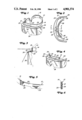
- FIG. 1 is a perspective of the shield.
- FIG. 2 is a plan view of the structure.
- FIG. 3 is a section, on an enlarged scale, taken on the line 3--3 of FIG. 2 and showing in broken lines an outline of the wearer's face and several positions of the shield relative to its full-line protective or normal mode.
- FIG. 4 is a perspective with the headband omitted.
- FIG. 5 is a fragmentary perspective showing the pocketed front portion of the headband.
- FIG. 6 is an enlarged section on the line 6--6 of FIG. 2.
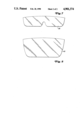
- FIG. 7 is a front view of one form of protective screen.
- FIG. 8 is a front view of another form of protective screen.
- the shield includes a head-encircling element (10) attached to a frontal part (12).
- the element includes a headband (14) of fabric or like material having provision for adjustment at (16).
- the frontal part is best seen in FIG. 4 as including a U-shaped strip (18) in the form of a wall configured to accommodate the wearer's forehead or brow.
- the strip is part of a compatibly configured shelf or ledge portion (20) having a central region or support portion (22) integral with the central region of the brow part (18), it being preferred that the portions (18) and (20) be of fairly rigid material such as any of the well-known plastics suitable for the purpose.
- portion (18) The attachment of the portion (18) to only the central region of the shelf or ledge, however, leaves the portion (18) with a pair of laterally outwardly extending wings (24) of relatively flexible nature, a result stemming from the separation of the wings from lateral portions of the ledge by spaces or slots (26).
- the front part of the headband (14) is of tubular construction and thus provides laterally oppositely opening pockets (28) for respectively receiving the wings (24).
- the portion of the band between the pockets, as at (30), is elastic so that, after each pocket is slipped inwardly onto its wing, the elastic portion draws the pockets together to establish the connection.
- the band is easily stretched oppositely to remove it from the wings for separate laundering, replacement, etc.
- the central portion (22) is of thicker section than the rest of the ledge and thus serves as part of a hinge (32) for the mounting of a U-shaped frame (34) generally horizontally coplanar with the ledge (20) and again configured according to the typical brow or forehead of a person.
- the hinge provides a transverse horizontal pivot confined generally centrally of the structure where the meeting portions of the frame and ledge are essentially straight.
- This hinge is disposed frontally for convenience in selective positioning of the frame and its depending protective screen (36), the frame having an underside channel (38) providing screen mounting means into which the upper portion of the screen is tightly but removably received.
- the screen (36) is shown in flat condition in FIG. 7 and is curved as seen in FIGS.
- the material of which the screen is made may be of polycarbonate, for example.
- the screen will be removed from the frame and will return to its flat status.
- An alternate screen is shown at (40) in FIG. 8, being of greater area than the screen (36), which may be required in certain conditions.
- the "normal" protective mode of the screen may be perceived as shown in full lines. Nevertheless, because of the forward location of the hinge (32), other protective modes may be used, such as swung back toward the face or forwardly away from but still in front of the face, as well as a upward or horizontal model. This is but one of the several features of the shield. Others, as already noted, are the simplicity of the construction, the easy separability of the few parts, the elimination of complicated fasteners, etc. Still other features will become apparent to those versed in the art, as will many alterations in and additions to the embodiment shown, all without departure from the spirit and scope of the invention.
Abstract
Description
Claims (5)
Priority Applications (2)
| Application Number | Priority Date | Filing Date | Title |
|---|---|---|---|
| US07/184,846 US4901374A (en) | 1988-04-22 | 1988-04-22 | Face shield |
| EP89107236A EP0338581A1 (en) | 1988-04-22 | 1989-04-21 | Face shield |
Applications Claiming Priority (1)
| Application Number | Priority Date | Filing Date | Title |
|---|---|---|---|
| US07/184,846 US4901374A (en) | 1988-04-22 | 1988-04-22 | Face shield |
Publications (1)
| Publication Number | Publication Date |
|---|---|
| US4901374A true US4901374A (en) | 1990-02-20 |
Family
ID=22678606
Family Applications (1)
| Application Number | Title | Priority Date | Filing Date |
|---|---|---|---|
| US07/184,846 Expired - Fee Related US4901374A (en) | 1988-04-22 | 1988-04-22 | Face shield |
Country Status (2)
| Country | Link |
|---|---|
| US (1) | US4901374A (en) |
| EP (1) | EP0338581A1 (en) |
Cited By (30)
| Publication number | Priority date | Publication date | Assignee | Title |
|---|---|---|---|---|
| US4955087A (en) * | 1988-09-15 | 1990-09-11 | Richard Perez | Combined visor and sunglasses assembly |
| US5056163A (en) * | 1990-05-15 | 1991-10-15 | Chou Chih T | Sweat-absorbing strip for sport goggles |
| US5213241A (en) * | 1991-02-27 | 1993-05-25 | Jeffrey Donald Dewar | Ski goggle protective device |
| US5469229A (en) * | 1992-03-20 | 1995-11-21 | Greenbaum; Steven S. | Multi-purpose protective eye shield |
| US5469578A (en) * | 1993-05-07 | 1995-11-28 | Varo, Inc. | Night vision goggle headgear mount |
| USD428620S (en) * | 1997-05-19 | 2000-07-25 | Thawatchai Maturaporn | Eye shield |
| US6357053B1 (en) * | 2000-11-29 | 2002-03-19 | Tzu-Feng Wang-Lee | Safety goggles |
| US6751811B1 (en) * | 2003-05-22 | 2004-06-22 | Joe D. Hill | Elastomeric tensioning system for head and ear mounted eyewear |
| US6964067B1 (en) | 2004-04-22 | 2005-11-15 | Utopia Optics International, Inc. | Hinged goggle |
| US20050268385A1 (en) * | 2004-04-22 | 2005-12-08 | Utopia Optics International, Inc. | Vented eyewear |
| US20080109949A1 (en) * | 2006-10-31 | 2008-05-15 | Kinsella Georgette U | Swim goggles fastener system |
| US20110225711A1 (en) * | 2010-03-19 | 2011-09-22 | Oakley, Inc. | Eyewear with rigid lens support |
| US8668330B2 (en) | 2010-08-13 | 2014-03-11 | Oakley, Inc. | Eyewear with lens retention mechanism |
| US8677517B1 (en) | 2006-06-09 | 2014-03-25 | Revision Military Inc. | Visor system for helmet |
| US8746877B2 (en) | 2009-01-09 | 2014-06-10 | Oakley, Inc. | Eyewear with enhanced ballistic resistance |
| US8911076B2 (en) | 2008-07-03 | 2014-12-16 | Oakley, Inc. | Floating lens mounting system |
| US20170079364A1 (en) * | 2014-11-20 | 2017-03-23 | Paulson Manufacturing Corporation | Protective face shield |
| US9709817B2 (en) | 2015-12-07 | 2017-07-18 | Oakley, Inc. | Eyewear retention devices and methods |
| US9717631B2 (en) | 2012-08-31 | 2017-08-01 | Oakley, Inc. | Eyewear having multiple ventilation states |
| USD834755S1 (en) * | 2017-08-21 | 2018-11-27 | Ali Schempp | Combination eye mask and face cover |
| US10156734B2 (en) | 2015-12-08 | 2018-12-18 | Oakley, Inc. | Eyewear traction devices and methods |
| US10274748B2 (en) | 2014-03-27 | 2019-04-30 | Oakley, Inc. | Mounting mechanism for eyewear |
| US10359642B2 (en) | 2016-04-22 | 2019-07-23 | Oakley, Inc. | Mounting mechanism for eyewear |
| US10357400B2 (en) | 2012-12-11 | 2019-07-23 | Oakley, Inc. | Eyewear with outriggers |
| USD863689S1 (en) * | 2018-03-26 | 2019-10-15 | Dexerials Corporation | Protective cover for eyes |
| US10687981B2 (en) | 2015-10-09 | 2020-06-23 | Oakley, Inc. | Headworn supports with passive venting and removable lens |
| US10925772B2 (en) | 2013-03-07 | 2021-02-23 | Oakley, Inc. | Regeneratable anti-fogging element for goggle |
| USD938381S1 (en) * | 2021-01-26 | 2021-12-14 | Shenzhen Lvkun Business Consulting Co., Ltd. | Music blindfold |
| USD946549S1 (en) * | 2021-05-14 | 2022-03-22 | Qiuhong Wang | Wireless headband |
| USD956857S1 (en) * | 2021-04-16 | 2022-07-05 | Christian Dior Couture | Sunglasses |
Citations (10)
| Publication number | Priority date | Publication date | Assignee | Title |
|---|---|---|---|---|
| US1455025A (en) * | 1921-12-14 | 1923-05-15 | Jenny Karl Kern | Self-acting eye protector |
| US2393955A (en) * | 1944-02-04 | 1946-02-05 | Polaroid Corp | Visor attachment for goggles and the like |
| US2408273A (en) * | 1944-01-05 | 1946-09-24 | Robert H Sager | Sunshade and other auxiliary spectacles |
| US2700765A (en) * | 1952-12-13 | 1955-02-01 | Willson Products Inc | Detachable lens construction for protective glasses |
| US2829374A (en) * | 1956-02-15 | 1958-04-08 | Chicago Eye Shield Company | Face shield and adjustable head band therefor |
| US3016542A (en) * | 1959-12-28 | 1962-01-16 | Welsh Mfg Co | Goggle with lifting cover |
| US3016543A (en) * | 1959-12-28 | 1962-01-16 | Welsh Mfg Co | Goggle with lifting cover |
| US3214767A (en) * | 1962-12-20 | 1965-11-02 | Chicago Eye Shield Company | Face shield |
| US3663959A (en) * | 1968-11-15 | 1972-05-23 | Rene Loubeyre | Snow-goggles |
| US4541125A (en) * | 1983-08-19 | 1985-09-17 | Phillips Robert J | Eyeglasses apparatus, and methods of constructing and utilizing same |
Family Cites Families (4)
| Publication number | Priority date | Publication date | Assignee | Title |
|---|---|---|---|---|
| GB945756A (en) * | 1961-06-14 | 1964-01-08 | Stadium Ltd | Improvements in motor-cycling accessories |
| FR1477618A (en) * | 1966-03-04 | 1967-04-21 | Lifting screen protection device | |
| US3594816A (en) * | 1969-12-18 | 1971-07-27 | American Safety Equip | Safety helmet face shield |
| FR2477410A1 (en) * | 1980-03-04 | 1981-09-11 | Blanc Tailleur Philippe | Motorcyclists goggles - have front transparent screen hinging upwards on horizontal axis when obscured by mud |
-
1988
- 1988-04-22 US US07/184,846 patent/US4901374A/en not_active Expired - Fee Related
-
1989
- 1989-04-21 EP EP89107236A patent/EP0338581A1/en not_active Ceased
Patent Citations (10)
| Publication number | Priority date | Publication date | Assignee | Title |
|---|---|---|---|---|
| US1455025A (en) * | 1921-12-14 | 1923-05-15 | Jenny Karl Kern | Self-acting eye protector |
| US2408273A (en) * | 1944-01-05 | 1946-09-24 | Robert H Sager | Sunshade and other auxiliary spectacles |
| US2393955A (en) * | 1944-02-04 | 1946-02-05 | Polaroid Corp | Visor attachment for goggles and the like |
| US2700765A (en) * | 1952-12-13 | 1955-02-01 | Willson Products Inc | Detachable lens construction for protective glasses |
| US2829374A (en) * | 1956-02-15 | 1958-04-08 | Chicago Eye Shield Company | Face shield and adjustable head band therefor |
| US3016542A (en) * | 1959-12-28 | 1962-01-16 | Welsh Mfg Co | Goggle with lifting cover |
| US3016543A (en) * | 1959-12-28 | 1962-01-16 | Welsh Mfg Co | Goggle with lifting cover |
| US3214767A (en) * | 1962-12-20 | 1965-11-02 | Chicago Eye Shield Company | Face shield |
| US3663959A (en) * | 1968-11-15 | 1972-05-23 | Rene Loubeyre | Snow-goggles |
| US4541125A (en) * | 1983-08-19 | 1985-09-17 | Phillips Robert J | Eyeglasses apparatus, and methods of constructing and utilizing same |
Cited By (39)
| Publication number | Priority date | Publication date | Assignee | Title |
|---|---|---|---|---|
| US4955087A (en) * | 1988-09-15 | 1990-09-11 | Richard Perez | Combined visor and sunglasses assembly |
| US5056163A (en) * | 1990-05-15 | 1991-10-15 | Chou Chih T | Sweat-absorbing strip for sport goggles |
| US5213241A (en) * | 1991-02-27 | 1993-05-25 | Jeffrey Donald Dewar | Ski goggle protective device |
| US5469229A (en) * | 1992-03-20 | 1995-11-21 | Greenbaum; Steven S. | Multi-purpose protective eye shield |
| US5469578A (en) * | 1993-05-07 | 1995-11-28 | Varo, Inc. | Night vision goggle headgear mount |
| USD428620S (en) * | 1997-05-19 | 2000-07-25 | Thawatchai Maturaporn | Eye shield |
| US6357053B1 (en) * | 2000-11-29 | 2002-03-19 | Tzu-Feng Wang-Lee | Safety goggles |
| US6751811B1 (en) * | 2003-05-22 | 2004-06-22 | Joe D. Hill | Elastomeric tensioning system for head and ear mounted eyewear |
| US6964067B1 (en) | 2004-04-22 | 2005-11-15 | Utopia Optics International, Inc. | Hinged goggle |
| US20050268385A1 (en) * | 2004-04-22 | 2005-12-08 | Utopia Optics International, Inc. | Vented eyewear |
| US20050268384A1 (en) * | 2004-04-22 | 2005-12-08 | James Hartman | Hinged goggle |
| US7058991B2 (en) | 2004-04-22 | 2006-06-13 | Utopia Optics International, Inc. | Vented eyewear |
| US8677517B1 (en) | 2006-06-09 | 2014-03-25 | Revision Military Inc. | Visor system for helmet |
| US20080109949A1 (en) * | 2006-10-31 | 2008-05-15 | Kinsella Georgette U | Swim goggles fastener system |
| US8911076B2 (en) | 2008-07-03 | 2014-12-16 | Oakley, Inc. | Floating lens mounting system |
| US8746877B2 (en) | 2009-01-09 | 2014-06-10 | Oakley, Inc. | Eyewear with enhanced ballistic resistance |
| US20110225711A1 (en) * | 2010-03-19 | 2011-09-22 | Oakley, Inc. | Eyewear with rigid lens support |
| US20110225710A1 (en) * | 2010-03-19 | 2011-09-22 | Oakley, Inc. | Eyewear with enhanced pressure distribution |
| US8661562B2 (en) | 2010-03-19 | 2014-03-04 | Oakley, Inc. | Eyewear with rigid lens support |
| US20110225709A1 (en) * | 2010-03-19 | 2011-09-22 | Oakley, Inc. | Eyewear with interchangeable lens mechanism |
| US8800067B2 (en) | 2010-03-19 | 2014-08-12 | Oakley, Inc. | Eyewear with interchangeable lens mechanism |
| US8850626B2 (en) | 2010-03-19 | 2014-10-07 | Oakley, Inc. | Eyewear with enhanced pressure distribution |
| US8881316B2 (en) * | 2010-03-19 | 2014-11-11 | Oakley, Inc. | Eyewear with rigid lens support |
| US8668330B2 (en) | 2010-08-13 | 2014-03-11 | Oakley, Inc. | Eyewear with lens retention mechanism |
| US9717631B2 (en) | 2012-08-31 | 2017-08-01 | Oakley, Inc. | Eyewear having multiple ventilation states |
| US10335317B2 (en) | 2012-08-31 | 2019-07-02 | Oakley, Inc. | Eyewear having multiple ventilation states |
| US10357400B2 (en) | 2012-12-11 | 2019-07-23 | Oakley, Inc. | Eyewear with outriggers |
| US10925772B2 (en) | 2013-03-07 | 2021-02-23 | Oakley, Inc. | Regeneratable anti-fogging element for goggle |
| US10274748B2 (en) | 2014-03-27 | 2019-04-30 | Oakley, Inc. | Mounting mechanism for eyewear |
| US20170079364A1 (en) * | 2014-11-20 | 2017-03-23 | Paulson Manufacturing Corporation | Protective face shield |
| US10687981B2 (en) | 2015-10-09 | 2020-06-23 | Oakley, Inc. | Headworn supports with passive venting and removable lens |
| US9709817B2 (en) | 2015-12-07 | 2017-07-18 | Oakley, Inc. | Eyewear retention devices and methods |
| US10156734B2 (en) | 2015-12-08 | 2018-12-18 | Oakley, Inc. | Eyewear traction devices and methods |
| US10359642B2 (en) | 2016-04-22 | 2019-07-23 | Oakley, Inc. | Mounting mechanism for eyewear |
| USD834755S1 (en) * | 2017-08-21 | 2018-11-27 | Ali Schempp | Combination eye mask and face cover |
| USD863689S1 (en) * | 2018-03-26 | 2019-10-15 | Dexerials Corporation | Protective cover for eyes |
| USD938381S1 (en) * | 2021-01-26 | 2021-12-14 | Shenzhen Lvkun Business Consulting Co., Ltd. | Music blindfold |
| USD956857S1 (en) * | 2021-04-16 | 2022-07-05 | Christian Dior Couture | Sunglasses |
| USD946549S1 (en) * | 2021-05-14 | 2022-03-22 | Qiuhong Wang | Wireless headband |
Also Published As
| Publication number | Publication date |
|---|---|
| EP0338581A1 (en) | 1989-10-25 |
Similar Documents
| Publication | Publication Date | Title |
|---|---|---|
| US4901374A (en) | Face shield | |
| US4853974A (en) | Frameless face protector | |
| US4520801A (en) | Cervical collar | |
| US4793334A (en) | Cervical brace | |
| US5483699A (en) | Face shield with chin contacting element | |
| EP0949874B1 (en) | Face mask having a combination adjustable ear loop and drop down band | |
| US4808160A (en) | Nasal cannula apparatus | |
| US4703879A (en) | Night vision goggle headgear | |
| US3991753A (en) | Device for preventing an individual from inhaling germs, foreign bodies, or the like | |
| US4995115A (en) | Garment for a wheelchair occupant | |
| US4819274A (en) | Visor cap with a detachable eye shield | |
| US4653123A (en) | Aerodynamic bicyclist's helmet construction | |
| US5003968A (en) | Head support | |
| US4051556A (en) | Chin strap for protective headgear | |
| US5788658A (en) | Field adjustable extrication collar | |
| US4468816A (en) | Nursing garment | |
| US3308816A (en) | Quick donning frame for respirator masks and the like | |
| US1309783A (en) | Hyman slawin | |
| US5704072A (en) | Occipital retention strap for cyclist headgear | |
| US6952841B2 (en) | Sports goggles | |
| US5099525A (en) | Face protecting mask intended to be used in general medicine and more particularly in surgery | |
| EP0181925A1 (en) | Convertible sunvisor cap | |
| SE463345B (en) | CERVIKALKRAGE | |
| US2671898A (en) | Light shield | |
| US5539931A (en) | Bare shoulder protector |
Legal Events
| Date | Code | Title | Description |
|---|---|---|---|
| AS | Assignment |
Owner name: PRO LENS, 106 NINTH STREET, ROCK ISLAND, ILLINOIS, Free format text: ASSIGNMENT OF ASSIGNORS INTEREST.;ASSIGNOR:VAN DER WOUDE, GERBRIG W.;REEL/FRAME:004896/0876 Effective date: 19880413 Owner name: PRO LENS, A CORP. OF ILLINOIS,ILLINOIS Free format text: ASSIGNMENT OF ASSIGNORS INTEREST;ASSIGNOR:VAN DER WOUDE, GERBRIG W.;REEL/FRAME:004896/0876 Effective date: 19880413 |
|
| FEPP | Fee payment procedure |
Free format text: PAYOR NUMBER ASSIGNED (ORIGINAL EVENT CODE: ASPN); ENTITY STATUS OF PATENT OWNER: SMALL ENTITY |
|
| REMI | Maintenance fee reminder mailed | ||
| LAPS | Lapse for failure to pay maintenance fees | ||
| FP | Lapsed due to failure to pay maintenance fee |
Effective date: 19930220 |
|
| STCH | Information on status: patent discontinuation |
Free format text: PATENT EXPIRED DUE TO NONPAYMENT OF MAINTENANCE FEES UNDER 37 CFR 1.362 |