EP3385149B1 - Dispositif de direction assistée électrique - Google Patents
Dispositif de direction assistée électrique Download PDFInfo
- Publication number
- EP3385149B1 EP3385149B1 EP15909771.6A EP15909771A EP3385149B1 EP 3385149 B1 EP3385149 B1 EP 3385149B1 EP 15909771 A EP15909771 A EP 15909771A EP 3385149 B1 EP3385149 B1 EP 3385149B1
- Authority
- EP
- European Patent Office
- Prior art keywords
- motor
- failure
- unit
- determination
- rotation angle
- Prior art date
- Legal status (The legal status is an assumption and is not a legal conclusion. Google has not performed a legal analysis and makes no representation as to the accuracy of the status listed.)
- Active
Links
- 238000001514 detection method Methods 0.000 claims description 159
- 238000012360 testing method Methods 0.000 claims description 82
- 230000005856 abnormality Effects 0.000 claims description 39
- 230000004044 response Effects 0.000 claims description 18
- 230000000694 effects Effects 0.000 description 26
- 238000000034 method Methods 0.000 description 25
- 230000003247 decreasing effect Effects 0.000 description 20
- 238000010586 diagram Methods 0.000 description 14
- 230000006866 deterioration Effects 0.000 description 9
- 230000008859 change Effects 0.000 description 6
- 230000001360 synchronised effect Effects 0.000 description 6
- 101100135611 Arabidopsis thaliana PAP12 gene Proteins 0.000 description 5
- 101100348113 Mus musculus Neurod6 gene Proteins 0.000 description 5
- 230000008901 benefit Effects 0.000 description 4
- 230000009466 transformation Effects 0.000 description 4
- 230000002441 reversible effect Effects 0.000 description 3
- 230000003044 adaptive effect Effects 0.000 description 2
- 230000002159 abnormal effect Effects 0.000 description 1
- 239000000470 constituent Substances 0.000 description 1
- 238000012937 correction Methods 0.000 description 1
- 238000011161 development Methods 0.000 description 1
- 238000005516 engineering process Methods 0.000 description 1
- 238000001914 filtration Methods 0.000 description 1
- 230000004907 flux Effects 0.000 description 1
- -1 i.e. Proteins 0.000 description 1
- 230000006872 improvement Effects 0.000 description 1
- 230000006698 induction Effects 0.000 description 1
- 230000007246 mechanism Effects 0.000 description 1
- 230000002265 prevention Effects 0.000 description 1
- 238000012545 processing Methods 0.000 description 1
- 238000005070 sampling Methods 0.000 description 1
- 230000035945 sensitivity Effects 0.000 description 1
- 238000000844 transformation Methods 0.000 description 1
Images


Classifications
-
- B—PERFORMING OPERATIONS; TRANSPORTING
- B62—LAND VEHICLES FOR TRAVELLING OTHERWISE THAN ON RAILS
- B62D—MOTOR VEHICLES; TRAILERS
- B62D5/00—Power-assisted or power-driven steering
- B62D5/04—Power-assisted or power-driven steering electrical, e.g. using an electric servo-motor connected to, or forming part of, the steering gear
- B62D5/0457—Power-assisted or power-driven steering electrical, e.g. using an electric servo-motor connected to, or forming part of, the steering gear characterised by control features of the drive means as such
- B62D5/0481—Power-assisted or power-driven steering electrical, e.g. using an electric servo-motor connected to, or forming part of, the steering gear characterised by control features of the drive means as such monitoring the steering system, e.g. failures
- B62D5/0487—Power-assisted or power-driven steering electrical, e.g. using an electric servo-motor connected to, or forming part of, the steering gear characterised by control features of the drive means as such monitoring the steering system, e.g. failures detecting motor faults
-
- B—PERFORMING OPERATIONS; TRANSPORTING
- B62—LAND VEHICLES FOR TRAVELLING OTHERWISE THAN ON RAILS
- B62D—MOTOR VEHICLES; TRAILERS
- B62D5/00—Power-assisted or power-driven steering
- B62D5/04—Power-assisted or power-driven steering electrical, e.g. using an electric servo-motor connected to, or forming part of, the steering gear
- B62D5/0457—Power-assisted or power-driven steering electrical, e.g. using an electric servo-motor connected to, or forming part of, the steering gear characterised by control features of the drive means as such
- B62D5/046—Controlling the motor
- B62D5/0463—Controlling the motor calculating assisting torque from the motor based on driver input
-
- B—PERFORMING OPERATIONS; TRANSPORTING
- B62—LAND VEHICLES FOR TRAVELLING OTHERWISE THAN ON RAILS
- B62D—MOTOR VEHICLES; TRAILERS
- B62D5/00—Power-assisted or power-driven steering
- B62D5/04—Power-assisted or power-driven steering electrical, e.g. using an electric servo-motor connected to, or forming part of, the steering gear
- B62D5/0457—Power-assisted or power-driven steering electrical, e.g. using an electric servo-motor connected to, or forming part of, the steering gear characterised by control features of the drive means as such
- B62D5/0481—Power-assisted or power-driven steering electrical, e.g. using an electric servo-motor connected to, or forming part of, the steering gear characterised by control features of the drive means as such monitoring the steering system, e.g. failures
- B62D5/0484—Power-assisted or power-driven steering electrical, e.g. using an electric servo-motor connected to, or forming part of, the steering gear characterised by control features of the drive means as such monitoring the steering system, e.g. failures for reaction to failures, e.g. limp home
-
- B—PERFORMING OPERATIONS; TRANSPORTING
- B62—LAND VEHICLES FOR TRAVELLING OTHERWISE THAN ON RAILS
- B62D—MOTOR VEHICLES; TRAILERS
- B62D5/00—Power-assisted or power-driven steering
- B62D5/04—Power-assisted or power-driven steering electrical, e.g. using an electric servo-motor connected to, or forming part of, the steering gear
- B62D5/0457—Power-assisted or power-driven steering electrical, e.g. using an electric servo-motor connected to, or forming part of, the steering gear characterised by control features of the drive means as such
- B62D5/0481—Power-assisted or power-driven steering electrical, e.g. using an electric servo-motor connected to, or forming part of, the steering gear characterised by control features of the drive means as such monitoring the steering system, e.g. failures
- B62D5/049—Power-assisted or power-driven steering electrical, e.g. using an electric servo-motor connected to, or forming part of, the steering gear characterised by control features of the drive means as such monitoring the steering system, e.g. failures detecting sensor failures
-
- B—PERFORMING OPERATIONS; TRANSPORTING
- B62—LAND VEHICLES FOR TRAVELLING OTHERWISE THAN ON RAILS
- B62D—MOTOR VEHICLES; TRAILERS
- B62D5/00—Power-assisted or power-driven steering
- B62D5/04—Power-assisted or power-driven steering electrical, e.g. using an electric servo-motor connected to, or forming part of, the steering gear
- B62D5/0409—Electric motor acting on the steering column
Definitions
- the present invention relates to an electric power steering apparatus and particularly to an electric power steering apparatus that quickly stops driving of a motor when a failure occurs in the motor that produces torque for assisting the driver's vehicle steering or in a control apparatus that controls the motor.
- Patent Document 1 discloses an integrated electric power steering apparatus in which a motor and a control apparatus that controls the motor are integrated with each other.
- Patent Document 2 discloses an electric power steering apparatus that continues driving of a switching device that controls a motor, for a time period from a time point when a control apparatus detects a suspicion of a short-to-ground failure to a time point when whether the suspicion of the short-to-ground failure is correct or incorrect is determined, and concurrently limits a voltage to be supplied from an electric power supply means to the switching device.
- Patent Document 3 discloses an electric power steering apparatus in which while the electric power steering apparatus operates, the inherent resistance value of a motor is calculated so that when the rotation speed of the motor is the same as or lower than a predetermined value and the motor current is the same as or larger than a predetermined value, it is made possible to accurately perform decrease correction of a target current signal for driving the motor.
- Patent Document 4 discloses a synchronous-motor control apparatus that includes an adaptive observer that calculates an angular frequency, an estimation current of a synchronous motor, an estimation rotor magnetic flux, and an estimation rotation speed, based on a current on a rotating 2-axis coordinates (d-q axes) and a voltage command on the rotating 2-axis coordinates (d-q axes) and an inverter that applies a voltage to the synchronous motor, based on the voltage command, and that configures the adaptive observer on the rotating 2-axis coordinates so that the synchronous motor can be controlled at a high rotation speed.
- an adaptive observer that calculates an angular frequency, an estimation current of a synchronous motor, an estimation rotor magnetic flux, and an estimation rotation speed, based on a current on a rotating 2-axis coordinates (d-q axes) and a voltage command on the rotating 2-axis coordinates (d-q axes)
- an inverter that applies a voltage to the synchronous motor, based on
- Patent Document 5 discloses an electric power steering apparatus that includes an electric-power supply unit that supplies to an AC motor high-frequency electric power on which high-frequency components corresponding to an inputted high-frequency signal are superimposed and a rotation position estimation unit that estimates a rotation position of the AC motor, and makes the rotation position estimation unit calculate the rotation position of the AC motor, based on the phase difference between an output-torque high-frequency wave included in the output torque of the AC motor and the high-frequency signal and hence accurately estimates the rotation position of the AC motor, without being restricted by the rotation speed, occurrence of magnetic-field axis saturation, or the like, so that the AC motor can accurately be controlled.
- an electric power steering device for controlling a motor for giving the steering assist force to a steering mechanism on the basis of a steering assist command value, which is computed by a computing means on the basis of the steering torque and a car speed and a motor current value, is provided with a function for continuing the assist by adding a limitation to the assist when a fine failure unnecessary to stop a system is generated.
- a character gain of the current control value corresponding to the steering torque is limited at 1/n and while a limitation target value is provided in the 1/n limitation characteristic.
- an electric power steering apparatus is provided with a motor that produces torque for assisting steering by a driver who drives a vehicle and a control apparatus that controls the motor; in the case where a failure occurs in the motor or the control apparatus and hence an appropriate current cannot be supplied to the motor, there may be caused a case where there occurs a lock mode in which the motor does not rotate and hence it becomes difficult for the driver to perform intended steering. Therefore, with regard to an electric power steering apparatus, as is well known, it is required to take measures, for example, such as immediately stopping the driving of the motor, when an failure occurs in the motor or the control apparatus.
- a failure determination means is configured in such a way that the effect of a disturbance or the like that occurs with a magnitude in proportion to the current of the motor is considered so that erroneous failure detection is prevented; however, in this case, there have been problems, for example, that when a failure actually occurs, it takes a long time before the failure is detected and that the accuracy of failure detection is deteriorated.
- the failure determination method is configured in such a way that erroneous failure detection caused by a disturbance or the like is prevented, there has been a problem that when the failure determination method and the determination method for the suspicion of a failure are the same, it takes a long time before the driving of the motor is restricted and hence the time during which the motor is locked becomes long.
- the present invention has been implemented in order to solve the foregoing problem in a conventional electric power steering apparatus; the objective thereof is to obtain an electric power steering apparatus that prevents the situation in which when a failure occurs, the motor is locked and hence the steering becomes difficult and that rapidly and appropriately detects the failure and can stop the driving of the motor.
- the detection of a failure in an appropriate manner means that when a failure occurs, the failure is securely detected and that in a normal state where no failure has occurred, no erroneous failure detection is performed.
- An electric power steering apparatus includes a torque detection unit that detects steering torque produced by a driver of a vehicle, a motor that assists steering by a driver, an assist command generation unit that generates an assist command corresponding to the steering torque, a motor driving unit that drives the motor, based on the assist command, and a failure determination unit that performs determination on a failure in the motor or the motor driving unit; the electric power steering apparatus wherein when the state where steering torque detected by the torque detection unit is normal and the value thereof is the same as or larger than a predetermined threshold value continues, the assist command generation unit limits the assist command, in that the failure determination unit includes a first failure determination unit that performs determination on the failure regardless of the limitation of the assist command and a second failure determination unit that performs determination on the failure when the limitation is applied to the assist command, and in that when the second failure determination unit determines that the failure exists, the failure determination unit stops driving of the motor.
- the present invention makes it possible to provide an electric power steering apparatus that prevents the situation in which the motor is locked and hence the steering becomes difficult and that more rapidly and appropriately detects a failure and can stop the driving of the motor.
- the detection of a failure in an appropriate manner means that when a failure occurs, the failure is securely detected and that in a normal state where no failure has occurred, no erroneous failure detection is performed.
- each of [ ⁇ L ⁇ id] and [ ⁇ L ⁇ iq] is a disturbance that is proportional to the current; thus, because the larger the current is, the larger the effect of the voltage disturbance becomes, the control accuracy of the current control device is deteriorated.
- the symbol f is an induced voltage constant.
- the current difference between a target current and an actual current becomes large. Also in the case where a failure occurs in the motor or the control apparatus and hence no appropriate current is applied to the motor, the current difference becomes large. Accordingly, there has been a problem that for example, in the case where the failure determination is performed through a failure determination method or by a failure determination means in which when the current difference is large, it is determined that a failure has occurred and the effect of the voltage disturbance in proportion to the motor current deteriorates the control accuracy, it is erroneously determined that a failure has occurred, i.e., an erroneous failure detection is performed, although no failure has occurred, and then the driving of the motor is stopped.
- the failure determination method or the failure determination means for preventing the erroneous detection of a failure in which, for example, the threshold value for detecting a failure is enlarged, the failure-determination sensitivity at a time when a failure actually occurs is deteriorated; thus, the failure-detection accuracy is deteriorated, for example, it takes a long time before the failure is detected.
- the failure-detection accuracy is deteriorated, for example, it takes a long time before the failure is detected.
- improvement of the failure detection performance and prevention of the erroneous detection are in a trade-off relationship, it is difficult to balance them.
- a motor-rotation-angle estimation value ⁇ est is obtained by integrating a motor-rotation-speed estimation value ⁇ est, as expressed by the equation (2) below.
- the motor-rotation-speed estimation value ⁇ est is estimated based on the after-mentioned equation (3) including a voltage vq, a resistance value R and an induced voltage constant f, set as parameters, and a current iq.
- the resistance value R set as a parameter, includes a parameter error ⁇ R between the real value and the set value.
- the motor-rotation-speed estimation value west is calculate based on the resistance value R, which is set as a parameter, and the current iq; thus, the estimation error of the motor rotation angle increases in proportion to the parameter error ⁇ R and the current iq.
- the estimation accuracy for the motor rotation angle is raised in inverse proportion to the value of the current; thus, it becomes more easy to distinguish the deterioration of the control performance caused by the deterioration of the estimation accuracy from a failure.
- the steering torque value increases and becomes a predetermined value or larger, and this state continues. Accordingly, when although the motor outputs the auxiliary torque, the state where detected steering torque is normal and the steering torque value is the predetermined value or larger continues, it can be determined that there exists a suspect that the motor or the ECU, which is a control apparatus for the motor has failed; however, the torque detection unit is not involved in this determination.
- the motor is locked, it is made possible to reduce the reverse-direction torque of the motor by limiting and decreasing the motor current; thus, the state where the motor is locked can be released.
- the electric power steering apparatus according to the present invention is provided with a configuration with the foregoing problems are solved and a failure can more quickly and appropriately be detected.
- FIG. 1 is a conceptual diagram representing the overall configuration of an electric power steering apparatus according to Embodiment 1 of the present invention.
- an electric power steering apparatus mounted in a vehicle includes a steering wheel 101, a steering shaft 103, a torque detection unit 102 provided on the steering shaft 103, a rack-and-pinion gear 105, wheels 104, a motor 1 that assists steering of a driver, a control apparatus (hereinafter, referred to as an ECU) 106 that supplies the motor 1 with electric power for driving the motor 1 and controls driving of the motor 1, and a torque detection unit 102 that detects steering torque produced by the driver.
- an ECU control apparatus
- steering torque exerted on the steering wheel 101 from an unillustrated driver is transferred to a rack in the rack-and-pinion gear 105, through the intermediaries of a torsion bar provided in the torque detection unit 102 and the steering shaft 103, so that the wheels 104 are steered.
- Output torque produced by the motor 1 is transferred to the steering shaft 103 so as to reduce steering torque to be exerted by the driver during steering.
- a publicly well-known motor such as a permanent magnet synchronous motor, a DC-brush motor, or an induction motor may be utilized.
- the motor 1 is a 3-phase AC permanent magnet synchronous motor.
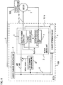
- FIG. 2 is a configuration diagram of the control apparatus in the electric power steering apparatus according to Embodiment 1 of the present invention.
- ECU 106 includes an assist command generation unit 2 that generates and outputs a d-axis assist command id* and a q-axis assist command iq* corresponding to steering torque ⁇ that is produced by the driver and is detected by the torque detection unit 102, a motor driving unit 3 that drives the motor 1, based on the d-axis assist command id* and the q-axis assist command iq*, and a failure determination unit 4 that performs determination on a failure in the motor 1 or the motor driving unit 3.
- an assist command generation unit 2 that generates and outputs a d-axis assist command id* and a q-axis assist command iq* corresponding to steering torque ⁇ that is produced by the driver and is detected by the torque detection unit 102
- a motor driving unit 3 that drives the motor 1, based on the d-axis assist command
- the motor driving unit 3 includes an electric-power supply unit 5, a current detection unit 6, and a motor rotation angle detection unit 7.
- the d-axis assist command id* and the q-axis assist command iq* may collectively be referred to only as “assist commands id* and iq*" or "assist commands”.
- the electric-power supply unit 5 inputs a d-axis current id and a q-axis current iq of the motor to the failure determination unit 4.
- the failure determination unit 4 includes a first failure determination unit and a second failure determination unit, described later.
- the motor rotation angle detection unit 7 detects a rotation angle ⁇ of the rotor of the motor 1 and inputs the rotation angle ⁇ to the electric-power supply unit 5.
- the motor rotation angle detection unit 7 is formed of, for example, a resolver, a rotary encoder, or the like.
- the assist command generation unit 2 calculates the assist commands id* and iq* and then inputs the assist commands id* and iq* to the electric-power supply unit 5 and the failure determination unit 4.
- the method of calculating the assist commands id* and iq* is not particularly specified; however, for example, the assist command iq* is calculated in such a way that id* is set to "0" and then the steering torque ⁇ is multiplied by a proportional gain Ka.
- the maximum value of each of the assist commands id* and iq* outputted by the assist command generation unit 2 is, for example, the rated current of the motor 1.
- the assist command generation unit 2 limits the assist commands.
- the assist command generation unit 2 performs the limitation of the assist commands, for example, in such a way that iq*, which is an assist command, is limited to a value that is smaller than the maximum value of the assist command, for example, the same as or smaller than 1/4 or 1/10 of the rated current of the motor 1, or "0".
- the limitation of the assist commands may be performed in such a way that the limit values of the assist commands are instantaneously decreased or gradually decreased with time.
- the limitation of the assist commands is performed in such a way that the assist commands are gradually decreased up to 1/4 or smaller of the rated current of the motor 1.
- the condition that suggests that the steering torque ⁇ detected by the torque detection unit 102 is normal is not particularly specified; however, the foregoing condition suggests that the value of the steering torque ⁇ detected by the torque detection unit 102 is the same as or smaller than a first torque threshold value ⁇ 1, which is the upper limit of a normal range.
- a first torque threshold value ⁇ 1 which is the upper limit of a normal range.
- the assist command generation unit 2 limits the assist commands, on suspicion of a failure in the motor 1 or the motor driving unit 3. In this regard, however, ⁇ 2 is the same as or smaller than ⁇ 1.
- the second torque threshold value ⁇ 2 is only necessary to be a value with which it can be determined that the steering torque produced by the driver is large; for example, the value of ⁇ 2 is set to 0.9 times as large as ⁇ 1.
- the assist command generation unit 2 turns on an assist command limiting flag F0 while the assist commands id* and iq* are limited, and inputs the assist command limiting flag F0 to the failure determination unit 4.
- the motor driving unit 3 includes an electric-power supply unit 5, the current detection unit 6, and the motor rotation angle detection unit 7 .
- the electric-power supply unit 5 applies three-phase voltages vu, vv, and vw to the armature coil of the motor 1, which is a 3-phase AC permanent magnet synchronous motor.
- the current detection unit 6 detects the three-phase currents iu, iv, and iw that flow due to the application of three-phase voltages vu, vv, and vw from the electric-power supply unit 5 to the motor 1.
- the electric-power supply unit 5 calculates a d-axis voltage vd* and a q-axis voltage vq* on the d-axis and the q-axis, respectively, which are the rotating two axes, through the intermediary of a PI controller (unillustrated) .
- a PI controller unillustrated
- the current control device is a PI controller
- the current control device is not limited to a PI controller and the control method may be another control method such as PID control.
- the electric-power supply unit 5 coordinate-transform the d-axis voltage vd* and the q-axis voltage vq* on the d-axis and the q-axis, respectively, which are rotating two axes, into the three-phase voltages vu*, vv*, and vw*; based on the coordinate-transformed three-phase voltages vu*, vv*, and vw*, an inverter (unillustrated) applies the three-phase voltages vu, vv, and vw to the motor 1, so that the three-phase currents iu, iv, and iw are made to flow in the motor 1 and hence the motor 1 is driven.
- the failure determination unit 4 includes the first failure determination unit (unillustrated) and the second failure determination unit (unillustrated) .
- the failure determination unit 4 determines a failure in the part related to the path through which the three-phase currents iu, iv, and iw of the motor 1 flow, i.e., a failure in any one of the motor 1 and the motor driving unit 3.
- a failure in the motor driving unit 3 denotes a failure in any one of the electric-power supply unit 5 and the current detection unit 6.
- the failure determination unit 4 determines that a failure has occurred in the part related to the path through which the three-phase currents iu, iv, and iw of the motor 1 flow, the driving of the motor 1 by the motor driving unit 3 is stopped.
- Embodiment 1 in the case where a first abnormality determination state amount based on the state of the motor driving unit 3 is larger than a first determination threshold value ⁇ 1, the first failure determination unit determines that a failure has occurred in the motor 1 or the motor driving unit 3; in the case where the first abnormality determination state amount is larger than a second determination threshold value ⁇ 2, the second failure determination unit determines that a failure has occurred in the motor 1 or the motor driving unit 3.
- the second determination threshold value ⁇ 2 is smaller than the first determination threshold value ⁇ 1, i.e., ⁇ 2 ⁇ 1.
- the first abnormality determination state amount to be determined by the failure determination unit 4 is only necessary to be a state amount with which a failure in the part related to the path through which the three-phase currents iu, iv, and iw of the motor 1 can be determined.
- the first abnormality determination state amounts are only necessary to be the three-phase currents iu, iv, and iw of the motor 1, the three-phase voltages vu, vv, and vw that have respective correlations with the corresponding three-phase currents iu, iv, and iw, or values related to those.
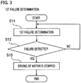
- FIG. 3 is a flowchart representing the operation of the first failure determination unit in the electric power steering apparatus according to Embodiment 1 of the present invention.
- the first failure determination unit performs a first failure determination in the step S11.
- a failure is determined regardless of the values of the assist commands id* and iq*.
- the failure determination condition is not particularly specified.
- the failure determination condition in the first failure determination unit is referred to as a first determination condition.
- the first determination condition is defined as follows.
- the first determination condition q-axis current difference ⁇ iq > the first determination threshold value ⁇ 1
- step S11 it is determined whether or not the first determination condition is satisfied; when the first determination condition is satisfied, it is determined that a failure exists in the motor 1 or the motor driving unit 3.
- step S12 it is determined whether or not the first failure determination unit has determined that a failure exists in the motor 1 or the motor driving unit 3 and has detected the failure; in the case where the first failure determination unit has detected the failure (YES), the step S12 is followed by the step S13, where the driving of the motor 1 by the motor driving unit 3 is stopped; in the case where the first failure determination unit has not detected the failure (NO), the step S11 is resumed, and the first failure determination by the first failure determination unit is repeated.
- FIG. 4 is a flowchart representing the operational actions of the assist command and the second failure determination unit in the electric power steering apparatus according to Embodiment 1 of the present invention.
- the step S21 it is determined whether or not the state where the value of the steering torque ⁇ detected by the torque detection unit 102 is the same as or smaller than the first torque threshold value ⁇ 1, which is the upper limit of a normal range, and the same as or larger than the second torque threshold value ⁇ 2 has continued for a predetermined time or longer; in the case where the result of the determination is affirmative (YES), the step S21 is followed by the step S22, where the assist commands id* and iq* are gradually decreased and limited, on suspicion of a failure in the motor 1 or the motor driving unit 3. In the case where the result of the determination in the step S21 is negative (NO), the step S21 is resumed and the foregoing determination is repeated.
- the assist commands id* and iq* are gradually decreased and limited; then, in the step S23, the second failure determination unit performs a second failure determination.
- the second failure determination by the second failure determination unit is performed while as described above, the assist commands id* and iq* are gradually decreased and limited. For example, after the assist commands id* and iq* are gradually decreased and limited up to 1/4 of the rated current of the motor 1 or smaller, the second failure determination is performed.
- the first abnormality determination state amount to be determined by the second failure determination is the q-axis current difference ⁇ iq.
- the second failure determination unit determines that a failure exists in the motor 1 or the motor driving unit 3.
- the second determination threshold value ⁇ 2 is smaller than the first determination threshold value ⁇ 1, i.e., ⁇ 2 ⁇ 1.
- the failure determination condition in the second failure determination unit is referred to as a second determination condition.
- the second determination condition is defined as follows.
- the second determination condition the q-axis current difference ⁇ iq > the second determination threshold value ⁇ 2
- the time during which the second determination condition is satisfied is measured for a first predetermined time T1; in the case where the measured time is the same as or longer than a second predetermined time T2, it is determined that a failure exists in the motor 1 or the motor driving unit 3.
- the measuring of this time is performed, for example, by sampling the values of the q-axis current differences ⁇ iq with a specific time period and counting the number of instances, in each of which the second determination condition is satisfied.
- the time in which the second determination condition is satisfied is not necessarily continuous; for example, the times, in each of which the second determination condition is satisfied, is integrated for the first predetermined time T1; in the case where the integrated time is the same as or longer than the second predetermined time T2, it may be determined that a failure exists in the motor 1 or the motor driving unit 3.
- This method makes it possible that even when for example, detection noise intrudes in the detected three-phase currents iu, iv, and iw and hence the second determination condition is temporarily unsatisfied, a failure can appropriately be determined.
- step S24 it is determined whether or not during a third predetermined time T3, the second failure determination unit has determined that a failure exists; in the case where during the third predetermined time T3, the second failure determination unit has not determined that a failure exists (NO), the step S24 is followed by the step S25, where the limitation of the assist commands is cancelled; then, the step S21 is resumed.
- step S25 the limitation of the assist commands id* and iq* is cancelled and then the assist is resumed.
- the limit values of the assist commands id* and iq* are gradually enlarged with time, i.e., gradually increased so as to be restored to the rated values of the motor 1. Due to the cancellation of the limitation of the assist commands, the steering torque necessary for the driver to perform steering is reduced.
- the assist commands id* and iq* may instantaneously be restored from the limit values to the rated values of the motor 1, in the case where during the third predetermined time T3, the second failure determination unit does not determine that a failure exists.
- the second failure determination unit does not determine that a failure exists.
- step S24 the step S24 is followed by the step S26, where the driving of the motor 1 by the motor driving unit 3 is stopped.
- an electric power steering apparatus includes a torque detection unit that detects steering torque produced by a driver, a motor that assists steering by a driver, an assist command generation unit that generates an assist command corresponding to the steering torque, a motor driving unit that drives the motor, based on the assist command, and a failure determination unit that performs determination on a failure in the motor or the motor driving unit; when the state where the steering torque detected by the torque detection unit is normal and the value of the steering torque is the same as or larger than a threshold value continues, the assist command generation unit limits the assist command; the failure determination unit includes a first failure determination unit that performs determination on the failure regardless of the limitation of the assist command and a second failure determination unit that performs determination on the failure while the assist command is limited, and stops driving of the motor when the second failure determination unit determines that there exists a failure.
- the second failure determination unit that performs determination on the failure while the assist command is limited makes it possible to prevent an erroneous detection caused by a voltage disturbance proportional to the current and to more rapidly and appropriately detect the failure.
- the first failure determination unit or the second failure determination unit determines that a failure exists in the motor or the motor driving unit, when a first abnormality determination state amount based on the state of the motor driving unit is larger than a first determination threshold value or the second determination threshold value, as the case may be, and the second determination threshold value is set to a value that is smaller than the first determination threshold value; therefore, the second failure determination unit more readily determines that a failure exists than the first failure determination unit determines and hence the failure can more rapidly and appropriately be detected.
- the assist command generation unit cancels the limitation of the assist command; thus, because when no failure exists, the limitation of the assist command is cancelled and hence the steering-power assistance by the motor can be resumed, there is demonstrated an advantage that the power required for steering is reduced.
- the motor driving unit includes a current detection unit that detects the current of the motor and an electric-power supply unit that supplies electric power to the motor, based on the assist command and the detected current; because the failure determination unit performs determination on a failure in the current detection unit or the electric-power supply unit, based on the current or the voltage of the motor, a voltage disturbance proportional to the current is decreased by reducing the assist command. As a result, it is made possible to more rapidly and appropriately detect a failure in the current detection unit or the electric-power supply unit related to the current flowing path.
- determination on a failure is performed after the assist command is limited up to 1/4 of the rated current of the motor or smaller; however, it may be allowed that the assist command is gradually decreased and limited up to "0" and that the determination of a failure is started when while gradually decreased, the assist command has been limited up to 1/4 of the rated current or smaller. In that case, because the determination of a failure is started when the assist command is being gradually decreased, it is made possible to more rapidly perform the determination of a failure in comparison with the case where the assist command is limited up to "0".
- the assist command is limited to "0", which is less than 1/4 of the rated current or smaller and with which the determination on a failure is readily performed, even when due to a failure, the motor performs reverse assisting, the motor is prevented from being locked by the reverse assisting.
- the failure determination condition is based on the current; however, the determination may be performed based on the voltage.
- the determination may be performed based on the q-axis voltage vq* instead of the q-axis current difference ⁇ iq. Because a voltage has the correlation with a current, determination on a failure can be performed in a manner the same as that in the case where the determination is performed based on the current.
- the second failure determination unit when during the third predetermined time, the second failure determination unit does not determine that a failure exists, the limitation of the assist command is cancelled; however, it may be allowed that the limitation of the assist command is not cancelled but continued.
- the state where the second failure determination unit readily performs determination on a failure can be maintained; therefore, when a failure occurs, the driving of the motor can immediately be stopped.
- FIG. 5 is a configuration diagram of the control apparatus in the electric power steering apparatus according to Embodiment 2 of the present invention.
- the failure determination method in Embodiment 2 differs from that in Embodiment 1; however, other configurations in Embodiment 2 are the same as those in Embodiment 1.
- Embodiment 2 the part, in Embodiment 2, that is different from that in Embodiment 1 will be explained.
- the first failure determination unit in the failure determination unit 4 represented in FIG. 5 determines that a failure has occurred in the motor 1 or the motor driving unit 3; in the case where the second abnormality determination state amount based on the state of the motor driving unit 3 is larger than the second determination threshold value ⁇ 22, the second failure determination unit determines that a failure has occurred in the motor 1 or the motor driving unit 3; the first abnormality determination state amount and the second abnormality determination state amount are respective state amounts that are different from each other.
- each of the first failure determination unit and the second failure determination unit has the configuration, described below.
- the first failure determination unit performs a first failure determination, regardless of the values of the assist commands id* and iq*.
- the failure determination condition is not particularly specified.
- the first abnormality determination state amount is set to the d-axis voltage vd*.
- the first failure determination unit determines that a failure exists in the motor 1 or the motor driving unit 3.
- the failure determination condition in the first failure determination unit is referred to as a first determination condition that is defined as follows.
- the second failure determination unit performs determination on a failure while the d-axis assist command id* and the q-axis assist command iq* are limited. For example, after the d-axis assist commands id* and the q-axis assist command iq* are gradually decreased and limited up to 1/4 of the rated current of the motor 1 or smaller, the failure determination is performed.
- the second abnormality determination state amount is the q-axis voltage Vq*, which is an abnormality determination state amount that is different from the d-axis voltage vd* as the first abnormality determination state amount.
- the d-axis voltage vd* is always small and is independent from the q-axis voltage Vq*, and the determination on a failure is performed regardless of the value of the assist commands id* and iq*.
- the q-axis assist command iq* becomes large up to a value that is set as the maximum value (e.g., the rated current of the motor 1); thus, the failure determination is performed while the assist command is limited, for example, up to 1/4 of the rated current of the motor 1 or smaller.
- the failure determination condition in the second failure determination unit is referred to as a second determination condition that is defined as follows.
- the first abnormality determination state amount and the second abnormality determination state amount are set to respective abnormality determination state amounts that are different from each other; thus, it is made possible to widen the range of the condition with which a failure can be detected and hence a failure is more readily detected in comparison with the case where the determination on a failure is performed only by the first failure determination unit.
- an electric power steering apparatus includes a torque detection unit that detects steering torque produced by a driver, a motor that assists steering by a driver, an assist command generation unit that generates an assist command corresponding to the steering torque, a motor driving unit that drives the motor, based on the assist command, and a failure determination unit that performs determination on a failure in the motor or the motor driving unit; when the state where the steering torque detected by the torque detection unit is normal and the value of the steering torque is the same as or larger than a threshold value continues, the assist command generation unit limits the assist command; the failure determination unit includes a first failure determination unit that performs determination on the failure regardless of the limitation of the assist command and a second failure determination unit that performs determination on the failure while the assist command is limited, and stops driving of the motor when the second failure determination unit determines that there exists a failure.
- the second failure determination unit that performs determination on the failure while the assist command is limited makes it possible to prevent an erroneous detection caused by the effect of a voltage disturbance proportional to the current and to more rapidly and appropriately detect the failure.
- the first failure determination unit determines that a failure has occurred in the motor or the motor driving unit; in the case where the second abnormality determination state amount based on the state of the motor driving unit is larger than the second determination threshold value, the second failure determination unit determines that a failure has occurred in the motor or the motor driving unit; the first abnormality determination state amount and the second abnormality determination state amount are respective abnormality determination state amounts that are different from each other.
- the second failure determination unit performs determination on a failure with a determination condition that is different from that in the first failure determination unit, it is made possible to widen the range of the condition with which a failure can be detected and hence a failure is more readily detected in comparison with the case where the determination on a failure is performed by the first failure determination unit.
- the assist command generation unit cancels the limitation of the assist command; thus, because when no failure exists, the limitation of the assist command is cancelled and hence the steering-power assistance by the motor can be resumed, the power required for steering is reduced.
- the motor driving unit includes a current detection unit that detects the current of the motor and an electric-power supply unit that supplies electric power to the motor, based on the assist command and the detected current; because the failure determination unit performs determination on a failure in the current detection unit or the electric-power supply unit, based on the current or the voltage of the motor, a voltage disturbance proportional to the current is decreased by reducing the assist command. As a result, it is made possible to more rapidly and appropriately detect a failure in the current detection unit or the electric-power supply unit related to the current flowing path.
- Embodiment 3 differs from Embodiment 1 in the configuration of an ECU, as a control apparatus; the other configurations are the same as those in Embodiment 1.
- the part, in Embodiment 3, that is different from that in Embodiment 1 will mainly be explained.
- FIG. 6 is a configuration diagram of the control apparatus in the electric power steering apparatus according to Embodiment 3 of the present invention.
- the ECU 106 which is a control apparatus, has a test command generation unit 8 that generates test commands idh* and iqh* for performing determination on a failure, while as in the foregoing manner, the assist commands id* and iq* are limited.
- the motor driving unit 3 can drive the motor 1, based on the assist command to which as described later, the test commands idh* and iqh* from the test command generation unit 8 are added.
- the second failure determination unit in the failure determination unit 4 determines that a failure exists in the motor 1 or the motor driving unit 3.
- the configurations of the current detection unit 6 and the motor rotation angle detection unit 7 are the same as those in Embodiment 1.
- the assist command generation unit 2 is configured in the same manner as in Embodiment 1 and calculates and then outputs the assist commands id* and iq* corresponding to the steering torque ⁇ . In other words, in accordance with the steering torque ⁇ inputted from the torque detection unit 102, the assist command generation unit 2 calculates the assist commands id* and iq* and then inputs the assist commands id* and iq* to the electric-power supply unit 5.
- the method of calculating the assist commands id* and iq* is not particularly specified; however, for example, the assist command iq* is calculated in such a way that id* is set to "0" and then the steering torque ⁇ is multiplied by the proportional gain Ka.
- the maximum value of each of the assist commands id* and iq* outputted by the assist command generation unit 2 is, for example, the rated current of the motor 1.
- the assist command generation unit 2 limits the assist commands.
- the assist command generation unit 2 performs the limitation of the assist commands in such a way that iq*, which is an assist command, is limited to a value that is smaller than the maximum value of the assist command, for example, the same as or smaller than 1/4 or 1/10 of the rated current of the motor 1.
- the limitation of the assist commands may be performed in such a way that the limit values of the assist commands are instantaneously decreased or gradually decreased with time.
- the limitation of the assist commands is performed in such a way that the assist commands are gradually decreased to "0".
- the condition that suggests that the steering torque ⁇ detected by the torque detection unit 102 is normal is not particularly specified; however, the foregoing condition suggests, for example, that the value of the steering torque ⁇ detected by the torque detection unit 102 is the same as or smaller than a first torque threshold value ⁇ 1, which is the upper limit of a normal range.
- a first torque threshold value ⁇ 1 which is the upper limit of a normal range.
- the assist command generation unit 2 limits the assist commands, on suspicion of a failure in the motor 1 or the motor driving unit 3. In this regard, however, ⁇ 2 is the same as or smaller than ⁇ 1.
- the assist command generation unit 2 turns on a test command flag F while the assist commands id* and iq* are limited, and inputs the test command flag F to the test command generation unit 8 and the failure determination unit 4.
- the test command flag F is a flag to apply the test commands idh* and iqh* for performing determination on a failure. For example, the test command flag F is turned on after the assist commands id* and iq* are gradually decreased and limited to "0".
- test command generation unit 8 When the test command flag F is ON, the test command generation unit 8 generates and outputs the test commands idh* and iqh*. In other words, the test command generation unit 8 generates the test commands idh* and iqh* while the assist commands id* and iq* are limited.
- Each of the test commands idh* and iqh* is a signal that corresponds to a current on a fixed-coordinate axis and whose main component has a frequency wh that is higher than the mechanical resonance frequency of the steering.
- the test commands idh* and iqh* at a time point t are given by the equations (4) and (5), respectively.
- idh* Ah ⁇ sin wh ⁇ t
- iqh* Ah ⁇ cos wh ⁇ t
- the electric-power supply unit 5 calculates a d-axis voltage vd* and a q-axis voltage vq* on the d-axis and the q-axis, respectively, which are the rotating two axes, through the intermediary of a PI controller (unillustrated) .
- a PI controller unillustrated
- the current control device is a PI controller
- the current control device is not limited to a PI controller and the control method may be another control method such as PID control.
- the electric-power supply unit 5 coordinate-transform the d-axis voltage vd* and the q-axis voltage vq* on the d-axis and the q-axis, respectively, which are rotating two axes, into the three-phase voltages vu*, vv*, and vw*; based on the coordinate-transformed three-phase voltages vu*, vv*, and vw*, an inverter (unillustrated) applies the three-phase voltages vu, vv, and vw to the motor 1, so that the three-phase currents iu, iv, and iw are made to flow in the motor 1 and hence the motor 1 is driven.
- the failure determination unit 4 includes the first failure determination unit (unillustrated) and the second failure determination unit (unillustrated) .
- the failure determination unit 4 determines a failure in the part related to the path through which the three-phase currents iu, iv, and iw of the motor 1 flow, i.e., a failure in any one of the motor 1 and the motor driving unit 3.
- a failure in the motor driving unit 3 denotes a failure in any one of the electric-power supply unit 5 and the current detection unit 6.
- the failure determination unit 4 determines that a failure has occurred in the part related to the path through which the three-phase currents iu, iv, and iw of the motor 1 flow, the driving of the motor 1 by the motor driving unit 3 is stopped.
- the first failure determination unit is configured in the same manner as the first failure determination unit in foregoing Embodiment 1.
- the second failure determination unit determines that a failure exists in the motor 1 or the motor driving unit 3.
- the state where the second abnormality determination state amount, which is a value related to the response of the motor 1 is smaller than the second determination threshold value ⁇ continues for a predetermined time.
- the second abnormality determination state amounts, the d-axis current id and the q-axis current iq are utilized, and the second determination threshold value ⁇ is set to Ah/2, as a value that is smaller than the amplitude Ah of the test command.
- the test commands idh* and iqh* is a sinusoidal wave of 125 [Hz]
- one period is 8[ms].
- the value of each of the d-axis current id and the q-axis current iq which are the responses of the motor 1, becomes larger than the second determination threshold value ⁇ in 4[ms], which is the half period.
- the d-axis current id and the q-axis current iq which are abnormal determination state amounts, are utilized in a failure determination, after the high-frequency components thereof are extracted through filtering processing by a bandpass filter or the like. In that case, because the determination can be performed without the effects of an offset or noise, the determination on a failure can more appropriately be performed.
- the configuration of the electric power steering apparatus according to Embodiment 3 of the present invention brings about the following effects. That is to say, when the state where the steering torque detected by the torque detection unit is normal and the value of the steering torque is the same as or larger than a threshold value continues, the assist command is limited; the failure determination unit includes a first failure determination unit that performs determination on the failure regardless of the limitation of the assist command and a second failure determination unit that performs determination on the failure while the assist command is limited, and stops driving of the motor when the second failure determination unit determines that there exists a failure.
- the limitation of the assist command makes it possible to reduce the current of the motor, the motor is prevented from being locked; concurrently, the second failure determination unit that performs determination on the failure while the assist command is limited makes it possible to prevent an erroneous detection caused by the effect of a voltage disturbance proportional to the current and to more rapidly and appropriately detect the failure.
- a test command generation unit that generates a test command for performing determination on the failure, while the assist commands are limited; the motor driving unit drives the motor, based on the test command; in the case where the response of the motor does not reflect the test command, the second failure determination unit determines that a failure exists in the motor or the motor driving unit.
- the second failure determination unit which performs determination on a failure by use of the test command, more readily performs determination on a failure than the first failure determination unit. Because the assist command is made small, the response based on the test command is more readily extracted and hence an erroneous determination becomes unlikely to occur.
- test command has its main component having a frequency higher than the mechanical resonance frequency of the steering, the effect thereof to steering is suppressed in comparison with the case where a lower frequency is applied.
- the second failure determination unit determines that a failure exists; thus, it can be determined that there exists a failure, because while driving is performed based on the test command, the response of the motor does not reflect the test command.
- the assist command generation unit cancels the limitation of the assist command; thus, because when no failure exists, the limitation of the assist command is cancelled and hence the steering-power assistance by the motor can be resumed, the power required for steering is reduced.
- the motor driving unit includes a current detection unit that detects the current of the motor and an electric-power supply unit that supplies electric power to the motor, based on the assist command and the detected current; because the failure determination unit performs determination on a failure in the current detection unit or the electric-power supply unit, based on the current or the voltage of the motor, a voltage disturbance proportional to the current is decreased by reducing the assist command. As a result, it is made possible to more rapidly and appropriately detect a failure in the current detection unit or the electric-power supply unit related to the current flowing path.
- each of the test commands idh* and iqh* is a sinusoidal wave of 125 [Hz]; however, the test command is not limited to a sinusoidal wave, and there may be utilized any signal whose main component has a frequency higher than the mechanical resonance frequency of the steering.
- the test commands idh* and iqh* is configured with a sawtooth wave, a triangular wave, a rectangular wave, a pulse waveform, or the like, the failure determination can be performed in the same manner.
- the frequency of each of the test commands idh* and iqh* is not limited to 125[Hz] whose one period is 8[ms]; the frequency thereof may be any frequency higher than the mechanical resonance frequency of the steering. For example, the frequency thereof may be either 62.5[Hz] whose one period is 16[ms] or 250[Hz] whose one period is 4[ms].
- Embodiment 4 is different from Embodiment 3 in terms of the configurations of the test command generation unit and the second failure determination unit; other configurations are the same as those in Embodiment 3.
- FIG. 7 is a configuration diagram of the control apparatus in the electric power steering apparatus according to Embodiment 4 of the present invention.
- the test command generation unit 8 when the test command flag F is ON, the test command generation unit 8 generates the test commands iah* and ibh* by use of the motor rotation angle ⁇ detected by the motor rotation angle detection unit 7.
- the test commands iah* and ibh* on the fixed-coordinate axis expressed by the following equations (6) and (7), are converted, through the equation (8) below, into the idh* and iqh* on the d axis and the q axis, which are rotating two axes, based on the detected motor rotation angle ⁇ , and are utilized as the test commands.
- the second failure determination unit measures a time A in which during the first predetermined time T1, each of the three-phase currents iu, iv, and iw becomes the same as or larger than a positive threshold value a and a time B in which each of the three-phase currents iu, iv, and iw becomes the same as or smaller than a negative threshold value b; in the case where the time A or the time B is the same as or shorter than the second predetermined time T2, the second failure determination unit determines that a failure exists in the motor 1 or the motor driving unit 3, because the response of the motor does not reflect the test command.
- the failure determination by the second failure determination unit in the case where the value of each of the three-phase currents iu, iv, and iw is smaller than a predetermined value, it can be determined that there exists a failure, because the response of the motor does not reflect the test command. Furthermore, with regard to the three-phase currents iu, iv, and iw, it is made possible to make a distinction between a failure related to the positive side and a failure related to the negative side.
- the second abnormality determination state amounts, the three-phase currents iu, iv, and iw are utilized, and the second determination threshold value ⁇ is set to, for example, Ah/2, as a value that is smaller than the amplitude Ah of the test command.
- the each of the three-phase currents iu, iv, and iw is the same as or smaller than the second determination threshold value ⁇ , it can be determined that a failure exists in the motor 1 or the motor driving unit 3, because the response of the motor does not reflect the test commands.
- the method described below makes it possible to perform a failure determination while making a distinction between a failure related to the positive side and a failure related to the negative side.
- a failure related to the positive side for example, when each of the test commands iah* and ibh* is a sinusoidal wave of 125[Hz], one period thereof is 8[ms]; thus, the first predetermined time T1 is set to 8[ms].
- the current iu will be explained; however, the same determination method can be applied also to the currents iv and iw. Assuming that a positive threshold value a is Ah/2, the time A in which the current iu is the same as or larger than the positive threshold value a is measured.
- the second predetermined time T2 is only necessary to be a value with which it can be determined that the time in which the current iu is positive is short.
- each of the test commands iah* and ibh* is a sinusoidal wave whose one period is 8[ms]
- the time in which the current iu is the same as or larger than Ah/2 in one period becomes 8/3 [ms] .
- N2 is, for example, N/2, N/3, or the like. In this regard, however, each of N and N2 is an integer.
- the third predetermined time T3 is, for example, T1 ⁇ N.
- the failure determination unit includes a first failure determination unit that performs determination on the failure regardless of the limitation of the assist command and a second failure determination unit that performs determination on the failure while the assist command is limited, and stops driving of the motor when the second failure determination unit determines that there exists a failure.
- the limitation of the assist command makes it possible to reduce the current of the motor, the motor is prevented from being locked; concurrently, the second failure determination unit that performs determination on the failure while the assist command is limited makes it possible to prevent an erroneous detection caused by the effect of a voltage disturbance proportional to the current and to more rapidly and appropriately detect the failure.
- a test command generation unit that generates a test command for performing determination on the failure, while the assist commands are limited; the motor driving unit drives the motor, based on the test command; in the case where the response of the motor does not reflect the test command, the second failure determination unit determines that a failure exists in the motor or the motor driving unit.
- the second failure determination unit which performs determination on a failure by use of the test command, more readily performs determination on a failure than the first failure determination unit. Because the assist command is made small, the response based on the test command is more readily extracted and hence an erroneous determination becomes unlikely to occur.
- test command has its main component having a frequency higher than the mechanical resonance frequency of the steering, the effect thereof to steering is suppressed in comparison with the case where a lower frequency is applied.
- the second failure determination unit determines that a failure exists; thus, it can be determined that there exists a failure, because while driving is performed based on the test command, the response of the motor does not reflect the test command.
- the second failure determination unit measures a time A in which during the first predetermined time T1, the currents of the respective phases become the same as or larger than a positive threshold value a and a time B in which the currents of the respective phases become the same as or smaller than a negative threshold value b; in the case where the time A or the time B is the same as or shorter than the second predetermined time T2, the second failure determination unit determines that a failure exists; thus, when the time A in which the response of the test command is the same as or larger than the threshold value a, which is a positive value, is shorter than the second predetermined time T2, it can be determined that there exists a failure in which the current is not appropriately supplied in the positive direction. Similarly, there can also be determined a failure in which the current is not appropriately supplied in the negative direction; therefore, it is made possible to determine in which direction, i.e., in the positive or negative direction, a failure exists.
- the assist command generation unit cancels the limitation of the assist command; thus, because when no failure exists, the limitation of the assist command is cancelled and hence the steering-power assistance by the motor can be resumed, the power required for steering is reduced.
- the motor driving unit includes a current detection unit that detects the current of the motor and an electric-power supply unit that supplies electric power to the motor, based on the assist command and the detected current; because the failure determination unit performs determination on a failure in the current detection unit or the electric-power supply unit, based on the current or the voltage of the motor, a voltage disturbance proportional to the current is decreased by reducing the assist command. As a result, it is made possible to more rapidly and appropriately detect a failure in the current detection unit or the electric-power supply unit related to the current flowing path.
- Embodiment 5 is different from Embodiment 4 in terms of the configurations of the motor driving unit and the test command generation unit in the ECU, which is a control apparatus; other configurations are the same as those in Embodiment 4.
- FIG. 8 is a configuration diagram of the control apparatus in the electric power steering apparatus according to Embodiment 5 of the present invention.
- Embodiment 5 is different from Embodiment 4 in that there is provided a motor rotation angle estimation unit 9 that calculates an estimation value of the rotation angle of the motor 1 and in that based on a calculated motor rotation angle estimation value ⁇ est, the test commands idh* and iqh* are generated and electric power is supplied to the motor 1.
- the motor driving unit 3 includes the electric-power supply unit 5, the current detection unit 6, and the motor rotation angle estimation unit 9.
- the current detection unit 6 is configured in the same manner as the current detection unit in foregoing Embodiment 4.
- the motor rotation angle estimation unit 9 instead of the motor rotation angle detection unit, the motor rotation angle estimation unit 9 that calculates the motor rotation angle estimation value ⁇ est is provided in the motor driving unit 3.
- the configuration of the motor rotation angle estimation unit 9 is not particularly specified; however, for example, as disclosed in Patent Document 4, the motor rotation angle is estimated based on the current.
- the test command generation unit 8 coordinate-transforms the test commands iah* and ibh* on the fixed-coordinate axes, represented in the foregoing equations (6) and (7), into idh* and iqh* on the d axis and the q axis, respectively, which are rotating two axes, by use of the motor rotation angle estimation value ⁇ est, calculated by the motor rotation angle estimation unit 9, instead of the motor rotation angle ⁇ represented in the foregoing equation (8), and idh* and iqh* are utilized as the test commands; this particular configuration is different from the configuration of the test command generation unit in foregoing Embodiment 4.
- the electric-power supply unit 5 supplies electric power to the motor 1.
- the electric-power supply unit 5 coordinate-transforms the three-phase currents iu, iv, and iw detected by the current detection unit 6 into the current id and the current iq on the d axis and the q axis, respectively, which are rotating two axes, based on the motor rotation angle estimation value ⁇ est estimated by the motor rotation angle estimation unit 9.
- the voltages vd* and vq* are calculated based on the currents id and iq.
- the d-axis voltage vd* and the q-axis voltage vq* on the d axis and the q axis, respectively, which are rotating two axes are coordinate-transformed into the three-phase voltages vu*, vv*, and vw*.
- the inverter applies a voltage to the motor 1, based on the coordinate-transformed three-phase voltages vu*, vv*, and vw*, so that a the motor is energized and hence the motor is driven.
- the electric power steering apparatus includes, in the motor driving unit, a motor rotation angle estimation unit that calculates an estimation value of the motor rotation angle, and supplies electric power based on the estimated motor rotation angle, the effects of a voltage disturbance proportional to the current and an error in estimating the motor rotation angle can be reduced, in addition to the effects that are the same as those in Embodiment 4; concurrently, the second failure determination unit that performs determination on a failure while the assist command is limited makes it possible to perform a determination while making an accurate distinction between the deterioration in the control accuracy, caused by a voltage disturbance proportional to the current and an error in estimating the motor rotation angle and a failure in the motor or the motor driving unit. Therefore,
- the motor rotation angle estimation unit is configured as disclosed in Patent Document 4; however, as disclosed in Patent Document 5, another configuration also demonstrates the same effect as Embodiment 5 does, for example, based on the phase difference between the output torque frequency included in the output torque of the motor and the high-frequency signal, the motor rotation angle position is estimated.
- the motor rotation angle estimation unit according to Embodiment 5 is utilized, a more prominent effect is obtained.
- the motor driving unit in Embodiment 6 includes a motor rotation angle detection unit that detects the rotation angle of a motor and an angle detection failure determination unit that performs determination on a failure in the motor rotation angle detection unit.
- the motor driving unit and the test command generation unit differ from those in foregoing Embodiment 5 in that in the case where the motor rotation angle detection unit is normal, coordinate transformation in the electric-power supply unit is performed based on a detected motor rotation angle and in that in the case where the angle detection failure determination unit determines that a failure exists in the motor rotation angle detection unit, coordinate transformations in the electric-power supply unit and the test command generation unit are performed based on a motor rotation angle estimated by the motor rotation angle estimation unit; however, other configurations are the same as those in Embodiment 5.
- Embodiment 6 will be described by use of FIG. 8 in foregoing Embodiment 5.
- the motor rotation angle detection unit In the case where the motor rotation angle detection unit is normal, the electric-power supply unit 5 performs, as is the case with Embodiment 2, coordinate transformation between the three phases and the d and q axes, which are rotating two axes, based on the detected motor rotation angle ⁇ , and then supplies electric power to the motor. In the case where the motor rotation angle detection unit is normal, the limitation of the assist current, based on the steering torque, is not performed. In the failure determination unit 4, the first failure determination unit according to Embodiment 1 performs determination on a failure in the part related to the flowing path of the current of the motor 1.
- the angle detection failure determination unit determines whether or not a failure exists in the motor rotation angle detection unit.
- the determination condition is not particularly specified; it is only necessary that a failure in the motor rotation angle detection unit can appropriately be detected.
- the motor rotation angle is estimated in a manner the same as that described in Embodiment 5, and in the case where the absolute value of the difference between the detected motor rotation angle and the estimated motor rotation angle is the same as or larger than a threshold value, it is determined that a failure exits.
- the motor rotation angle estimation unit 9 calculates an motor-rotation-angle estimation value.
- the estimation of the motor rotation angle is performed in a manner the same as that described in Embodiment 5.
- the electric-power supply unit 5 performs, as is the case with Embodiment 5, coordinate transformation between the three phases and the d and q axes, which are rotating two axes, based on the estimated motor rotation angle instead of the detected motor rotation angle, and then supplies electric power to the motor.
- the test command generation unit 8 coordinate-transforms the test commands iah* and ibh* on the fixed-coordinate axes into the test commands idh* and iqh* on the d axis and the q axis, which are rotating two axes, based on the estimated motor rotation angle.
- the assist command generation unit 2 limits the assist command.
- the first failure determination unit and the second failure determination unit perform determination on a failure in the part related to the flowing path of the current of the motor, i.e., a failure in the motor, the current detection unit, or the electric-power supply unit.
- the motor driving unit includes a motor rotation angle detection unit that detects the rotation angle of the motor, an angle detection failure determination unit that performs determination on a failure in the motor rotation angle detection unit, and a motor rotation angle estimation unit that calculates an estimation value of the rotation angle of the motor; in the case where the motor rotation angle detection unit is normal, the motor driving unit supplies electric power, based on the detected motor rotation angle, and in the case where the angle detection failure determination unit determined that a failure exists, the motor driving unit supplies electric power, based on the estimated motor rotation angle; when the state where a failure exists in the motor rotation angle detection unit, the steering torque detected by the torque detection unit is normal, and the value of the steering torque is the same as or larger than a threshold value continues, the assist command generation unit limits the assist command. As a result, in addition to the effect of Embodiment 5, assist by the motor can be continued, because even when the motor angle detection unit fails, the motor can be driven, as backup control,
- the second failure determination unit performs determination on a failure while the assist command is limited, as is the case with Embodiment 5; thus, because after the backup control starts, it is made possible to make a distinction between control-accuracy deterioration caused by an error in the estimated angle and the failure and hence it is made possible to appropriately perform determination on a failure.
- Embodiment 7 is different from Embodiment 1 in that the second failure determination unit is provided with a normality determination unit that determines whether or not the determination subject has no failure and is normal; other configurations are the same as those in Embodiment 1.
- a normality determination unit that determines whether or not the determination subject of the second failure determination unit is normal is added to the second failure determination unit in the configuration of foregoing Embodiment 1. In the case where the normality determination unit determines that the determination subject of the second failure determination unit is normal, the limitation of the assist commands are cancelled.
- the normality determination condition it is adopted, as the normality determination condition, that the q-axis current difference ⁇ iq is smaller than a normality determination threshold value ⁇ 3; when the normality determination condition is satisfied for a fourth predetermined time T4 or longer, the normality determination unit determines that the determination subject of the second failure determination unit is normal.
- the normality determination threshold value ⁇ 3 is smaller than the second determination threshold value ⁇ 2, i.e., ⁇ 3 ⁇ ⁇ 2.
- the fourth predetermined time T4 is set to a time shorter than the third predetermined time T3 and when the normality determination unit determines that the determination subject is normal, the limitation of the assist commands is cancelled, the torque assistance by the motor is further rapidly obtained; thus, there is demonstrated an advantage that the steering torque required for the driver to steer is reduced.
- the second failure determination unit has a normality determination unit that determines, during the limitation of the assist commands, whether or not the motor or the motor driving unit has no failure and is normal; in the case where after the assist commands are limited, the first failure determination unit or the second failure determination unit does not determine that a failure exists during a predetermined time or determines that no abnormality exists, the assist command generation unit cancels the limitation of the assist commands.
- the normality determination unit makes it possible that when not failure exists, the assist can more rapidly be resumed.
- the normality determination unit is added to the configuration of Embodiment 1; however, even when the normality determination unit is provided in any other Embodiment, the same effect is obtained.
- FIG. 9 is a configuration diagram of the control apparatus in the electric power steering apparatus according to Embodiment 8 of the present invention.
- Embodiment 8 differs from Embodiment 1 in terms of the configuration of the failure determination unit in the ECU, which is a control apparatus; other configurations in Embodiment 8 are the same as those in Embodiment 1.
- the failure determination unit 4 in Embodiment 8 performs determination on a failure in the motor rotation angle detection unit 7.
- the motor rotation angle detection unit 7 is formed of, for example, a resolver that detects the motor rotation angle ⁇ from two kinds of AC voltages E1 and E2 having different phases; the AC voltages E1 and E2 and the motor rotation angle ⁇ are expressed in the equations (9), (10), and (11) below.
- E 1 Ar ⁇ sin ⁇ ⁇
- the failure determination unit 4 performs determination on a failure in the motor rotation angle detection unit, based on, for example, the amplitudes of the AC voltages E1 and E2. In this regard, however, when the assist command is large, electromagnetic noise caused by the motor current is large; thus, noise that is added to the signal of the motor rotation angle detection unit 7 becomes large. When the noise that is added to the signal of the motor rotation angle detection unit is large, it may be erroneously determined that a failure exists in the motor rotation angle detection unit. Accordingly, when the state where the steering torque detected by the torque detection unit is normal and the value of the steering torque is the same as or larger than a threshold value continues, the assist command generation unit limits the assist command on suspicion of a failure in the motor rotation angle detection unit.
- the first failure determination unit determines that a failure exists.
- the second determination condition based on a second determination threshold value Ath2 is continuously satisfied for a predetermined time, the second failure determination unit determines that a failure exists.
- the limitation of the assist command reduces the current to be energized to the motor and hence the noise that is added to the signal of the motor rotation angle detection unit becomes small
- the second determination threshold value Ath2 is set to a value smaller than the first determination threshold value Ath1, i.e., Ath2 ⁇ Ath1.
- the electric power steering apparatus includes a torque detection unit that detects steering torque produced by a driver, a motor that assists steering by a driver, an assist command generation unit that generates an assist command corresponding to the steering torque, a motor driving unit that drives the motor, based on the assist command, and a failure determination unit that performs determination on a failure in the motor or the motor driving unit; when the state where the steering torque detected by the torque detection unit is normal and the value of the steering torque is the same as or larger than a threshold value continues, the assist command generation unit limits the assist command; the failure determination unit includes a first failure determination unit that performs determination on the failure during the limitation of the assist command and a second failure determination unit that performs determination on the failure when the value of the assist command is small, and stops driving of the motor when the second failure determination unit determines that there exists a failure.
- the motor driving unit includes a current detection unit that detects the current of the motor, a motor rotation angle detection unit that detects the rotation angle of the motor, and an electric-power supply unit that supplies electric power to the motor, based on the assist command, the detected current, and the detected motor rotation angle; the failure determination unit performs determination on a failure in the current detection unit, the electric-power supply unit, or the motor rotation angle detection unit. Because the assist commands are limited through this configuration, the motor can be prevented from being locked when a failure causes reverse assisting.
- the limitation of the assist commands makes it possible to reduce the effect of electromagnetic noise to the motor angle detection unit; therefore, the determination threshold value in the second failure determination unit can be set to a value smaller than the first determination threshold value and hence determination on a failure can readily be performed.
- the second determination threshold value is set to a value smaller than the first determination threshold value; however, the second determination threshold value may be set to a value larger than the first determination threshold value, depending on the failure determination condition. For example, in the case where determination on a failure is performed based on the following first and second determination conditions, the determination on a failure is performed based on the amplitudes of the AC voltages E1 and E2; because the determination on a failure is performed based on whether or not the amplitude is small, the second determination threshold value is larger than the first determination threshold value. Similarly, in this case, the assist commands are limited and the second failure determination unit performs determination on a failure; thus, the determination on a failure is not erroneously performed and it is made possible to more rapidly determine that a failure exists.
- the failure determination unit performs determination on a failure in the motor rotation angle detection unit; however, it may be allowed that the foregoing method is combined with a method in which as another embodiment such as Embodiment 1, determination on a failure in the current detection unit or the electric-power supply unit is performed based on the motor current or the motor voltage and then determination on a failure in the current detection unit, the electric-power supply unit, or the motor rotation angle detection unit is performed. In that case, it is made possible to perform determination on a failure in more units.
- the motor rotation angle is estimated and determination on a failure in the motor rotation angle detection unit is performed based on the difference between the detected motor rotation angle ⁇ and the estimated motor rotation angle estimation value ⁇ est. For example, in the case where the absolute value of the difference between the detected motor rotation angle ⁇ and the estimated motor rotation angle estimation value ⁇ est is larger than a second determination threshold value Ath23, the second failure determination unit determines that a failure exists.
- the electric power steering apparatus in the case where the first abnormality determination state amount based on the state of the motor driving unit is larger than the first determination threshold value, the first failure determination unit determines that a failure exists in the motor or the motor driving unit; in the case where the second abnormality determination state amount based on the state of the motor driving unit is larger than the second determination threshold value, the second failure determination unit determines that a failure exists in the motor or the motor driving unit; the first abnormality determination state amount and the second abnormality determination state amount are respective state amounts that are different from each other.
- the second failure determination unit performs determination on a failure with a determination condition that is different from that in the first failure determination unit, it is made possible to widen the range of the condition with which a failure can be detected and hence a failure is more readily detected in comparison with the case where the determination on a failure is performed by the first failure determination unit.
- Embodiment 9 of the present invention will be explained.
- the configuration of the assist command generation unit 2 in the configuration of foregoing Embodiment 5 represented in FIG. 8 is changed in such a way as to limit the assist commands in the case where the steering torque ⁇ detected by the torque detection unit 102 is normal and the value thereof is the same as or larger than a predetermined threshold value and the state where the rotation speed of the motor 1 is the same as or lower than a predetermined threshold value continues.
- the motor rotation speed estimated by the motor rotation angle estimation unit 9 is utilized; alternatively, the rotation speed of the motor 1 is calculated by differentiating the motor rotation angle estimation value.
- the threshold value of the rotation speed of the motor 1 is set to a small value with which it can be determined that the motor 1 is locked.
- a value that is substantially zero may be utilized; the estimated motor rotation speed is set to, for example, 30 [rpm] or lower, in consideration of the fact that the estimated motor rotation speed has an error for the actual motor rotation speed.
- the assist command generation unit 2 is configured in such a way as to limit the assist commands in the case where the steering torque ⁇ detected by the torque detection unit 102 is normal and the value thereof is the same as or larger than a predetermined threshold value and the state where the rotation speed of the motor 1 is the same as or lower than a predetermined threshold value continues.
- the motor 1 is locked when the steering torque ⁇ is large and the motor rotation speed is substantially zero - the probability that the motor 1 is locked is extremely high.
- the fact that it can appropriately be determined that the motor 1 is locked suggests, i.e., that the assist commands can be prevented from being erroneously limited when the locking state has not occurred.
- the motor rotation angle estimation value estimated by the motor rotation angle estimation unit 9 is utilized; however, for example, as is the case with the configuration of Embodiment 1, the motor rotation angle detected by the motor rotation angle detection unit 7 may be utilized.
- Embodiment 10 of the present invention will be explained.
- the configuration of the assist command generation unit differs from that in Embodiment 5 represented in FIG. 7 ; however, other configurations in Embodiment 7 are the same as those in Embodiment 5.
- the assist command generation unit 2 determines whether or not the changes in the respective phases of the currents are small, and limits the assist commands id* and iq* when the state where the steering torque ⁇ detected by the torque detection unit 102 is normal and the value thereof is the same as or larger than a predetermined threshold value continues and it is determined that the changes in the respective phases of the detected three-phase currents iu, iv, and iw are small.
- the fact that the changes in the respective phases of the currents are small suggests that there exists probability of the lock state where the motor 1 does not rotate.
- the determination on whether or not the changes in the respective phases of the currents are small is performed in such a way that a time Tip in which the current is positive during a predetermined time and a time Tim in which the current is negative during the predetermined time are measured and then the determination is performed based on the proportion of Tip to Tim.
- the phase of the current is within the positive phase range; thus, it is determined that the change in the phase of the detected current is small. That fact that the phase of the current is within the positive phase range suggests, i.e., that the rotation angle of the motor 1 is within the angle range in which the current is positive.
- [Tip:Tim] becomes [1:1],[1:2], or[1:3]; thus, also in the case where the time Tip in which the current is positive is four or more times as long as the time Tim in which the current is negative, it is determined that the change in the phase of the current is small. Also in the case where the relationship between the positive and the negative is opposite to the foregoing relationship, it is determined that the change in the phase of the current is small.
- the assist command generation unit determines whether or not the changes in the respective phases of the currents are small, and limits the assist commands when the state where the steering torque detected by the torque detection unit is normal and the value thereof is the same as or larger than a threshold value continues and it is determined that the changes in the respective phases of the detected currents are small; as a result, it can appropriately be determined whether or not the motor is locked.
- a detected motor speed includes a detection error and an estimated motor speed includes an estimation error; therefore, by ascertaining whether or not the changes in the phases of the currents of the respective phases are small, it can more appropriately be determined whether or not the motor is locked.
- the present invention can be applied not only to the field of an electric power steering apparatus to be mounted in a vehicle such as an automobile but also to the field of a vehicle, such as an automobile, in which the electric power steering apparatus is mounted.
Claims (15)
- Appareil de direction assistée électrique comprenant :une unité de détection de couple (102) qui détecte un couple de direction produit par un conducteur d'un véhicule ;un moteur (1) qui fournit une direction assistée à un conducteur ;une unité de génération de commande d'assistance (2) qui génère une commande d'assistance correspondant au couple de direction ;une unité d'entraînement de moteur (3) qui entraîne le moteur (1), sur la base de la commande d'assistance ; etune unité de détermination de panne (4) qui effectue une détermination d'une panne dans le moteur (1) ou l'unité d'entraînement de moteur (3),dans lequel lorsque l'état dans lequel le couple de direction détecté par l'unité de détection de couple (102) est normal et la valeur de celui-ci est supérieure ou égale à une valeur seuil prédéterminée se maintient, l'unité de génération de commande d'assistance (2) limite la commande d'assistance,caractérisé en ce que l'unité de détermination de panne (4) inclut une première unité de détermination de panne qui effectue une détermination de la panne quelle que soit la limitation de la commande d'assistance et une seconde unité de détermination de panne qui effectue une détermination de la panne lorsque la limitation est appliquée à la commande d'assistance, etdans lequel lorsque la seconde unité de détermination de panne détermine que la panne existe, l'unité de détermination de panne (4) arrête l'entraînement du moteur (1).
- Appareil de direction assistée électrique selon la revendication 1,
dans lequel dans le cas où une quantité d'état de détermination d'anomalie sur la base d'un état de l'unité d'entraînement de moteur (3) est supérieure à une première valeur seuil de détermination, la première unité de détermination de panne détermine qu'une panne existe dans le moteur (1) ou l'unité d'entraînement de moteur (3),
dans lequel dans le cas où une quantité d'état de détermination d'anomalie sur la base d'un état de l'unité d'entraînement de moteur (3) est supérieure à une seconde valeur seuil de détermination, la seconde unité de détermination de panne détermine qu'une panne existe dans le moteur (1) ou l'unité d'entraînement de moteur (3), et
dans lequel la seconde valeur seuil de détermination est réglée sur une valeur inférieure à la première valeur seuil de détermination. - Appareil de direction assistée électrique selon la revendication 1,
dans lequel dans le cas où une première quantité d'état de détermination d'anomalie sur la base d'un état de l'unité d'entraînement de moteur (3) est supérieure à une première valeur seuil de détermination, la première unité de détermination de panne détermine qu'une panne existe dans le moteur (1) ou l'unité d'entraînement de moteur (3),
dans lequel dans le cas où une seconde quantité d'état de détermination d'anomalie sur la base d'un état de l'unité d'entraînement de moteur (3) est supérieure à une seconde valeur seuil de détermination, la seconde unité de détermination de panne détermine qu'une panne existe dans le moteur (1) ou l'unité d'entraînement de moteur (3), et
dans lequel la première quantité d'état de détermination d'anomalie et la seconde quantité d'état de détermination d'anomalie sont des quantités d'état qui sont différentes l'une de l'autre. - Appareil de direction assistée électrique selon l'une quelconque des revendications 1 à 3, incluant en outre une unité de génération de commande de test (8) qui génère une commande de test pour effectuer une détermination sur la panne, pendant que la commande d'assistance est limitée,
dans lequel l'unité d'entraînement de moteur (3) entraîne le moteur (1), compte tenu de la commande de test, et
dans lequel dans le cas où la réponse du moteur (1) ne reflète pas la commande de test, la seconde unité de détermination de panne détermine qu'une panne existe dans le moteur (1) ou l'unité d'entraînement de moteur (3). - Appareil de direction assistée électrique selon la revendication 4, dans lequel le composant principal de la commande de test a une fréquence supérieure à la fréquence de résonance mécanique de la direction du véhicule.
- Appareil de direction assistée électrique selon l'une quelconque des revendications 4 et 5, dans lequel dans le cas où la valeur du courant du moteur (1) est inférieure à une valeur prédéterminée, la seconde unité de détermination de panne détermine que la panne existe.
- Appareil de direction assistée électrique selon l'une quelconque des revendications 4 et 5, dans lequel la seconde unité de détermination de panne mesure une durée dans laquelle pendant une première durée prédéterminée T1, les courants des phases respectives du moteur (1) deviennent supérieurs ou égaux à une valeur seuil prédéterminée positive et une durée dans laquelle pendant la première durée prédétermine T1, les courants des phases respectives du moteur (1) deviennent inférieurs ou égaux à une valeur seuil prédéterminée négative ; dans le cas où la durée dans laquelle les courants des phases respectives du moteur (1) deviennent supérieurs ou égaux à la valeur seuil prédéterminée positive ou la durée dans laquelle les courants des phases respectives du moteur (1) deviennent inférieurs ou égaux à la valeur seuil prédéterminée négative est inférieure ou égale à une seconde durée prédéterminée T2, la seconde unité de détermination de panne détermine que la panne existe.
- Appareil de direction assistée électrique selon l'une quelconque des revendications 1 à 7, dans lequel dans le cas où lorsque la commande d'assistance est limitée, la seconde unité de détermination de panne ne détermine pas qu'une panne existe pendant une troisième durée prédéterminée T3, l'unité de génération de commande d'assistance (2) annule la limitation de la commande d'assistance.
- Appareil de direction assistée électrique selon la revendication 8,
dans lequel la seconde unité de détermination de panne a une unité de détermination de normalité qui détermine, pendant la limitation de la commande d'assistance, si le moteur (1) ou l'unité d'entraînement de moteur (3) présente ou non une panne et est ou non normal, et
dans lequel dans le cas où après la limitation de la commande d'assistance, la seconde unité de détermination de panne ne détermine pas qu'une panne existe pendant la troisième durée prédéterminée T3 ou détermine qu'aucune anomalie n'existe, l'unité de génération de commande d'assistance (2) annule la limitation de la commande d'assistance. - Appareil de direction assistée électrique selon l'une quelconque des revendications 1 à 9,
dans lequel l'unité d'entraînement de moteur (3) inclut une unité de détection de courant (6) qui détecte un courant du moteur (1) et une unité d'alimentation électrique (5) qui alimente le moteur (1) en énergie électrique, sur la base de la commande d'assistance et du courant détecté, et
dans lequel l'unité de détermination de panne (4) effectue la détermination sur une panne dans l'unité de détection de courant (6) ou de l'unité d'alimentation électrique (5), sur la base d'un courant ou d'une tension du moteur (1). - Appareil de direction assistée électrique selon l'une quelconque des revendications 1 à 10,
dans lequel l'unité d'entraînement de moteur (3) a une unité d'estimation d'angle de rotation moteur (9) qui calcule une valeur d'estimation de l'angle de rotation du moteur (1), et
dans lequel l'unité d'entraînement de moteur (3) fournit de l'énergie électrique au moteur (1), sur la base de la valeur d'estimation de l'angle de rotation du moteur (1). - Appareil de direction assistée électrique selon l'une quelconque des revendications 1 à 10,
dans lequel l'unité d'entraînement de moteur (3) inclut une unité de détection d'angle de rotation de moteur (7) qui détecte un angle de rotation du moteur (1), une unité de détermination de panne de détection d'angle qui effectue la détermination sur une panne dans l'unité de détection d'angle de rotation de moteur (7), et une unité d'estimation d'angle de rotation de moteur (9) qui calcule une valeur d'estimation de l'angle de rotation du moteur (1),
dans lequel dans le cas où l'unité de détection d'angle de rotation de moteur (7) est normale, l'unité d'entraînement de moteur (3) fournit de l'énergie électrique au moteur (1), sur la base de l'angle de rotation détecté du moteur (1) ; dans le cas où l'unité de détermination de panne de détection d'angle détermine qu'une panne existe dans l'unité de détection d'angle de rotation de moteur (7), l'unité d'entraînement de moteur (3) fournit de l'énergie électrique au moteur (1), sur la base de la valeur d'estimation de l'angle de rotation du moteur (1), et
dans lequel dans l'état dans lequel une panne existe dans l'unité de détection d'angle de rotation de moteur (7), le couple de direction détecté par l'unité de détection de couple (102) est normal et la valeur du couple de direction est supérieure ou égale à une valeur seuil prédéterminée se maintient, l'unité de génération de commande d'assistance (2) limite la commande d'assistance. - Appareil de direction assistée électrique selon l'une quelconque des revendications 1 à 12, dans lequel lorsque l'état dans lequel le couple de direction détecté par l'unité de détection de couple (102) est normal, la valeur du couple de direction est supérieure ou égale à une valeur seuil prédéterminée et la vitesse de rotation du moteur (1) est inférieure ou égale à une valeur seuil prédéterminée se maintient, l'unité de génération de commande d'assistance (2) limite la commande d'assistance.
- Appareil de direction assistée électrique selon l'une quelconque des revendications 1 à 13, dans lequel sur la base des positifs et des négatifs des courants détectés dans les phases respectives du moteur (1), l'unité de génération de commande d'assistance (2) détermine si les changements dans les phases respectives des courants sont ou non petits, et limite la commande d'assistance lorsque l'état dans lequel le couple de direction détecté par l'unité de détection de couple (102) est normal et la valeur du couple de direction est supérieure ou égale à une valeur seuil prédéterminée se maintient et il est déterminé que les changements dans les phases respectives des courants détectés sont petits.
- Appareil de direction assistée électrique selon l'une quelconque des revendications 1 à 9,
dans lequel l'unité d'entraînement de moteur (3) inclut une unité de détection de courant (6) qui détecte un courant du moteur (1), une unité de détection d'angle de rotation de moteur (7) qui détecte un angle de rotation du moteur (1) et une unité d'alimentation électrique (5) qui fournit de l'énergie électrique au moteur (1), sur la base de la commande d'assistance, du courant détecté et de l'angle de rotation détecté du moteur (1), et
dans lequel l'unité de détermination de panne (4) effectue la détermination sur une panne dans au moins une parmi l'unité de détection de courant (6), l'unité d'alimentation électrique (5) et l'unité de détection d'angle de rotation du moteur (7).
Applications Claiming Priority (1)
| Application Number | Priority Date | Filing Date | Title |
|---|---|---|---|
| PCT/JP2015/083884 WO2017094141A1 (fr) | 2015-12-02 | 2015-12-02 | Dispositif de direction assistée électrique |
Publications (3)
| Publication Number | Publication Date |
|---|---|
| EP3385149A1 EP3385149A1 (fr) | 2018-10-10 |
| EP3385149A4 EP3385149A4 (fr) | 2019-01-23 |
| EP3385149B1 true EP3385149B1 (fr) | 2020-03-04 |
Family
ID=58796597
Family Applications (1)
| Application Number | Title | Priority Date | Filing Date |
|---|---|---|---|
| EP15909771.6A Active EP3385149B1 (fr) | 2015-12-02 | 2015-12-02 | Dispositif de direction assistée électrique |
Country Status (5)
| Country | Link |
|---|---|
| US (1) | US10583859B2 (fr) |
| EP (1) | EP3385149B1 (fr) |
| JP (1) | JP6618548B2 (fr) |
| CN (1) | CN108290605B (fr) |
| WO (1) | WO2017094141A1 (fr) |
Families Citing this family (6)
| Publication number | Priority date | Publication date | Assignee | Title |
|---|---|---|---|---|
| US11404984B2 (en) * | 2018-06-20 | 2022-08-02 | Steering Solutions Ip Holding Corporation | Parameter learning for permanent magnet synchronous motor drives |
| KR102582336B1 (ko) * | 2018-06-25 | 2023-09-25 | 볼보 트럭 코퍼레이션 | 차량용 조향 어셈블리 |
| CN109318982B (zh) * | 2018-08-02 | 2021-05-25 | 江苏大学 | 一种混合动力转向系统参数匹配方法 |
| JP2020125996A (ja) * | 2019-02-05 | 2020-08-20 | 日本電産モビリティ株式会社 | 制御装置および制御方法 |
| CN110061674B (zh) * | 2019-03-29 | 2020-08-18 | 奥克斯空调股份有限公司 | 一种压缩机ipm驱动电流异常的控制方法、装置及空调器 |
| JP7131510B2 (ja) * | 2019-08-26 | 2022-09-06 | 株式会社デンソー | モータ制御装置 |
Family Cites Families (37)
| Publication number | Priority date | Publication date | Assignee | Title |
|---|---|---|---|---|
| JP2857903B2 (ja) * | 1990-01-17 | 1999-02-17 | 光洋精工株式会社 | 電動式パワーステアリング装置 |
| JP2864695B2 (ja) | 1990-08-31 | 1999-03-03 | スズキ株式会社 | 電動式パワーステアリング装置 |
| JP3028012B2 (ja) * | 1992-10-19 | 2000-04-04 | トヨタ自動車株式会社 | 車速感応型電動式パワーステアリング装置 |
| JP3229077B2 (ja) * | 1993-06-29 | 2001-11-12 | 本田技研工業株式会社 | 車輌用操舵装置 |
| JPH0923501A (ja) | 1995-07-03 | 1997-01-21 | Hitachi Ltd | 電気車制御装置 |
| JP3104865B2 (ja) * | 1997-08-25 | 2000-10-30 | 本田技研工業株式会社 | 電動パワーステアリング装置 |
| JP3652142B2 (ja) | 1998-11-10 | 2005-05-25 | 光洋精工株式会社 | パワーステアリング装置 |
| JP4119059B2 (ja) * | 1999-09-07 | 2008-07-16 | 本田技研工業株式会社 | 車両の協調制御装置 |
| JP4672236B2 (ja) * | 2001-04-24 | 2011-04-20 | 三菱電機株式会社 | 同期電動機の制御装置 |
| JP3600805B2 (ja) * | 2001-07-11 | 2004-12-15 | 三菱電機株式会社 | 電動パワーステアリング装置およびこれに用いられる異常検出時の制御方法 |
| JP2003170857A (ja) * | 2001-12-07 | 2003-06-17 | Nsk Ltd | 電動パワーステアリング装置 |
| JP3946994B2 (ja) * | 2001-12-17 | 2007-07-18 | 株式会社ジェイテクト | 電動パワーステアリング制御装置 |
| US7004279B2 (en) * | 2003-08-28 | 2006-02-28 | Nissan Motor Co., Ltd. | Vehicle steering system |
| JP2005212579A (ja) | 2004-01-29 | 2005-08-11 | Denso Corp | 電動パワーステアリング装置 |
| JP4319112B2 (ja) | 2004-08-27 | 2009-08-26 | 三菱電機株式会社 | 電動パワーステアリング装置 |
| JP2007253766A (ja) * | 2006-03-23 | 2007-10-04 | Nsk Ltd | 電動パワーステアリング装置 |
| JP4329792B2 (ja) * | 2006-08-10 | 2009-09-09 | トヨタ自動車株式会社 | 電動パワーステアリング装置 |
| JP4414424B2 (ja) | 2006-12-01 | 2010-02-10 | 本田技研工業株式会社 | 電動パワーステアリング装置 |
| JP5082666B2 (ja) | 2007-08-09 | 2012-11-28 | 株式会社ジェイテクト | モータ制御装置、伝達比可変装置及び車両用操舵装置 |
| JP4985561B2 (ja) * | 2008-06-24 | 2012-07-25 | トヨタ自動車株式会社 | 車両駆動用モータの制御装置 |
| JP2012111335A (ja) * | 2010-11-24 | 2012-06-14 | Showa Corp | 電動パワーステアリング装置、故障検出装置および故障検出方法 |
| JP5381968B2 (ja) * | 2010-12-21 | 2014-01-08 | 株式会社デンソー | トルクセンサ、トルク検出装置、および、これを用いた電動パワーステアリング装置。 |
| JP5621598B2 (ja) | 2011-01-06 | 2014-11-12 | 株式会社ジェイテクト | モータ制御装置及び電動パワーステアリング装置 |
| CN102959376B (zh) * | 2011-06-21 | 2015-02-04 | 日本精工株式会社 | 转矩检测装置及电动助力转向装置 |
| JP5440889B2 (ja) * | 2012-01-10 | 2014-03-12 | 株式会社デンソー | 電動パワーステアリング装置 |
| JP5436592B2 (ja) * | 2012-02-07 | 2014-03-05 | 三菱電機株式会社 | モータ制御装置、モータ制御装置に適用される電流制御方法、およびモータ制御装置を用いた電動パワーステアリング装置 |
| JP2013179742A (ja) | 2012-02-28 | 2013-09-09 | Fujitsu Ten Ltd | 異常検出装置、モータ制御装置及び異常検出方法 |
| JP2014100981A (ja) | 2012-11-19 | 2014-06-05 | Jtekt Corp | 電動パワーステアリング装置 |
| WO2014080497A1 (fr) | 2012-11-22 | 2014-05-30 | 三菱電機株式会社 | Dispositif de commande de machine tournante à courant alternatif, système d'entraînement de machine tournante à courant alternatif équipé d'un dispositif de commande de machine tournante à courant alternatif et système d'assistance électrique de direction |
| WO2014104253A1 (fr) * | 2012-12-28 | 2014-07-03 | 本田技研工業株式会社 | Dispositif de direction de véhicule |
| JP5817938B2 (ja) * | 2013-03-27 | 2015-11-18 | 日本精工株式会社 | 電動パワーステアリング装置 |
| JP6180771B2 (ja) * | 2013-03-29 | 2017-08-16 | 株式会社ジェイテクト | 電動パワーステアリング装置 |
| CN105473420B (zh) * | 2013-10-10 | 2017-07-11 | 日本精工株式会社 | 电动助力转向装置 |
| JP6237255B2 (ja) | 2014-01-20 | 2017-11-29 | 株式会社ジェイテクト | 電動パワーステアリング装置 |
| JP6299415B2 (ja) * | 2014-05-16 | 2018-03-28 | 株式会社ジェイテクト | ステアリング装置 |
| FR3039283B1 (fr) * | 2015-07-20 | 2017-07-21 | Continental Automotive France | Procede de detection d'un defaut de commande de couple d'un moteur electrique d'un systeme de direction assistee d'un vehicule automobile |
| US10071763B2 (en) * | 2015-08-28 | 2018-09-11 | Mitsubishi Electric Corporation | Electric power steering device |
-
2015
- 2015-12-02 CN CN201580084907.3A patent/CN108290605B/zh active Active
- 2015-12-02 WO PCT/JP2015/083884 patent/WO2017094141A1/fr active Application Filing
- 2015-12-02 EP EP15909771.6A patent/EP3385149B1/fr active Active
- 2015-12-02 JP JP2017553551A patent/JP6618548B2/ja active Active
- 2015-12-02 US US15/753,605 patent/US10583859B2/en active Active
Non-Patent Citations (1)
| Title |
|---|
| None * |
Also Published As
| Publication number | Publication date |
|---|---|
| JPWO2017094141A1 (ja) | 2018-07-05 |
| EP3385149A4 (fr) | 2019-01-23 |
| EP3385149A1 (fr) | 2018-10-10 |
| JP6618548B2 (ja) | 2019-12-11 |
| CN108290605B (zh) | 2020-08-25 |
| US20180257701A1 (en) | 2018-09-13 |
| WO2017094141A1 (fr) | 2017-06-08 |
| CN108290605A (zh) | 2018-07-17 |
| US10583859B2 (en) | 2020-03-10 |
Similar Documents
| Publication | Publication Date | Title |
|---|---|---|
| EP3385149B1 (fr) | Dispositif de direction assistée électrique | |
| US9475520B2 (en) | Rotational-angle detection device and electric power-steering device provided with rotational-angle detection device | |
| US9346486B2 (en) | Electric power steering system | |
| US9647603B2 (en) | Controller and control method for electric motor | |
| EP2518894B1 (fr) | Unité de commande de moteur et système de direction de véhicule | |
| JP5907314B2 (ja) | モータ制御装置、これを使用した電動パワーステアリング装置および車両 | |
| JP6624213B2 (ja) | 電動パワーステアリング装置 | |
| US9199665B2 (en) | Electric power steering system | |
| US20180175779A1 (en) | Controller and control method for electric motor | |
| US20030222612A1 (en) | Motor abnormality detection apparatus and electric power steering control system | |
| US7136733B2 (en) | Fault detection in an electric power-assisted steering system | |
| EP3450907B1 (fr) | Dispositif de détection d'angle et dispositif de commande de direction assistée électrique | |
| EP1835611B1 (fr) | Dispositif de contrôle de moteur pas à pas | |
| JP5423912B2 (ja) | 電動パワーステアリング装置 | |
| JP5570401B2 (ja) | 電動パワーステアリング装置 | |
| JP5062010B2 (ja) | 電動パワーステアリング装置 | |
| JP2016096608A (ja) | モータ制御装置、これを使用した電動パワーステアリング装置および車両 | |
| JP3915595B2 (ja) | レゾルバを用いた回転角度検出装置およびこの装置を用いた制御装置 |
Legal Events
| Date | Code | Title | Description |
|---|---|---|---|
| STAA | Information on the status of an ep patent application or granted ep patent |
Free format text: STATUS: THE INTERNATIONAL PUBLICATION HAS BEEN MADE |
|
| PUAI | Public reference made under article 153(3) epc to a published international application that has entered the european phase |
Free format text: ORIGINAL CODE: 0009012 |
|
| STAA | Information on the status of an ep patent application or granted ep patent |
Free format text: STATUS: REQUEST FOR EXAMINATION WAS MADE |
|
| 17P | Request for examination filed |
Effective date: 20180321 |
|
| AK | Designated contracting states |
Kind code of ref document: A1 Designated state(s): AL AT BE BG CH CY CZ DE DK EE ES FI FR GB GR HR HU IE IS IT LI LT LU LV MC MK MT NL NO PL PT RO RS SE SI SK SM TR |
|
| AX | Request for extension of the european patent |
Extension state: BA ME |
|
| REG | Reference to a national code |
Ref country code: DE Ref legal event code: R079 Ref document number: 602015048412 Country of ref document: DE Free format text: PREVIOUS MAIN CLASS: B62D0006000000 Ipc: B62D0005040000 |
|
| A4 | Supplementary search report drawn up and despatched |
Effective date: 20190103 |
|
| RIC1 | Information provided on ipc code assigned before grant |
Ipc: B62D 5/04 20060101AFI20181219BHEP |
|
| DAV | Request for validation of the european patent (deleted) | ||
| DAX | Request for extension of the european patent (deleted) | ||
| GRAP | Despatch of communication of intention to grant a patent |
Free format text: ORIGINAL CODE: EPIDOSNIGR1 |
|
| STAA | Information on the status of an ep patent application or granted ep patent |
Free format text: STATUS: GRANT OF PATENT IS INTENDED |
|
| INTG | Intention to grant announced |
Effective date: 20191105 |
|
| RIN1 | Information on inventor provided before grant (corrected) |
Inventor name: TSUCHIMOTO, YUYA Inventor name: NAKAJIMA, SHUNSUKE Inventor name: KEZOBO, ISAO |
|
| GRAS | Grant fee paid |
Free format text: ORIGINAL CODE: EPIDOSNIGR3 |
|
| GRAA | (expected) grant |
Free format text: ORIGINAL CODE: 0009210 |
|
| STAA | Information on the status of an ep patent application or granted ep patent |
Free format text: STATUS: THE PATENT HAS BEEN GRANTED |
|
| AK | Designated contracting states |
Kind code of ref document: B1 Designated state(s): AL AT BE BG CH CY CZ DE DK EE ES FI FR GB GR HR HU IE IS IT LI LT LU LV MC MK MT NL NO PL PT RO RS SE SI SK SM TR |
|
| REG | Reference to a national code |
Ref country code: GB Ref legal event code: FG4D |
|
| REG | Reference to a national code |
Ref country code: CH Ref legal event code: EP |
|
| REG | Reference to a national code |
Ref country code: AT Ref legal event code: REF Ref document number: 1240051 Country of ref document: AT Kind code of ref document: T Effective date: 20200315 |
|
| REG | Reference to a national code |
Ref country code: DE Ref legal event code: R096 Ref document number: 602015048412 Country of ref document: DE |
|
| REG | Reference to a national code |
Ref country code: IE Ref legal event code: FG4D |
|
| PG25 | Lapsed in a contracting state [announced via postgrant information from national office to epo] |
Ref country code: RS Free format text: LAPSE BECAUSE OF FAILURE TO SUBMIT A TRANSLATION OF THE DESCRIPTION OR TO PAY THE FEE WITHIN THE PRESCRIBED TIME-LIMIT Effective date: 20200304 Ref country code: FI Free format text: LAPSE BECAUSE OF FAILURE TO SUBMIT A TRANSLATION OF THE DESCRIPTION OR TO PAY THE FEE WITHIN THE PRESCRIBED TIME-LIMIT Effective date: 20200304 Ref country code: NO Free format text: LAPSE BECAUSE OF FAILURE TO SUBMIT A TRANSLATION OF THE DESCRIPTION OR TO PAY THE FEE WITHIN THE PRESCRIBED TIME-LIMIT Effective date: 20200604 |
|
| REG | Reference to a national code |
Ref country code: NL Ref legal event code: MP Effective date: 20200304 |
|
| PG25 | Lapsed in a contracting state [announced via postgrant information from national office to epo] |
Ref country code: GR Free format text: LAPSE BECAUSE OF FAILURE TO SUBMIT A TRANSLATION OF THE DESCRIPTION OR TO PAY THE FEE WITHIN THE PRESCRIBED TIME-LIMIT Effective date: 20200605 Ref country code: HR Free format text: LAPSE BECAUSE OF FAILURE TO SUBMIT A TRANSLATION OF THE DESCRIPTION OR TO PAY THE FEE WITHIN THE PRESCRIBED TIME-LIMIT Effective date: 20200304 Ref country code: LV Free format text: LAPSE BECAUSE OF FAILURE TO SUBMIT A TRANSLATION OF THE DESCRIPTION OR TO PAY THE FEE WITHIN THE PRESCRIBED TIME-LIMIT Effective date: 20200304 Ref country code: SE Free format text: LAPSE BECAUSE OF FAILURE TO SUBMIT A TRANSLATION OF THE DESCRIPTION OR TO PAY THE FEE WITHIN THE PRESCRIBED TIME-LIMIT Effective date: 20200304 Ref country code: BG Free format text: LAPSE BECAUSE OF FAILURE TO SUBMIT A TRANSLATION OF THE DESCRIPTION OR TO PAY THE FEE WITHIN THE PRESCRIBED TIME-LIMIT Effective date: 20200604 |
|
| REG | Reference to a national code |
Ref country code: LT Ref legal event code: MG4D |
|
| PG25 | Lapsed in a contracting state [announced via postgrant information from national office to epo] |
Ref country code: NL Free format text: LAPSE BECAUSE OF FAILURE TO SUBMIT A TRANSLATION OF THE DESCRIPTION OR TO PAY THE FEE WITHIN THE PRESCRIBED TIME-LIMIT Effective date: 20200304 |
|
| PG25 | Lapsed in a contracting state [announced via postgrant information from national office to epo] |
Ref country code: LT Free format text: LAPSE BECAUSE OF FAILURE TO SUBMIT A TRANSLATION OF THE DESCRIPTION OR TO PAY THE FEE WITHIN THE PRESCRIBED TIME-LIMIT Effective date: 20200304 Ref country code: ES Free format text: LAPSE BECAUSE OF FAILURE TO SUBMIT A TRANSLATION OF THE DESCRIPTION OR TO PAY THE FEE WITHIN THE PRESCRIBED TIME-LIMIT Effective date: 20200304 Ref country code: CZ Free format text: LAPSE BECAUSE OF FAILURE TO SUBMIT A TRANSLATION OF THE DESCRIPTION OR TO PAY THE FEE WITHIN THE PRESCRIBED TIME-LIMIT Effective date: 20200304 Ref country code: RO Free format text: LAPSE BECAUSE OF FAILURE TO SUBMIT A TRANSLATION OF THE DESCRIPTION OR TO PAY THE FEE WITHIN THE PRESCRIBED TIME-LIMIT Effective date: 20200304 Ref country code: SM Free format text: LAPSE BECAUSE OF FAILURE TO SUBMIT A TRANSLATION OF THE DESCRIPTION OR TO PAY THE FEE WITHIN THE PRESCRIBED TIME-LIMIT Effective date: 20200304 Ref country code: EE Free format text: LAPSE BECAUSE OF FAILURE TO SUBMIT A TRANSLATION OF THE DESCRIPTION OR TO PAY THE FEE WITHIN THE PRESCRIBED TIME-LIMIT Effective date: 20200304 Ref country code: IS Free format text: LAPSE BECAUSE OF FAILURE TO SUBMIT A TRANSLATION OF THE DESCRIPTION OR TO PAY THE FEE WITHIN THE PRESCRIBED TIME-LIMIT Effective date: 20200704 Ref country code: SK Free format text: LAPSE BECAUSE OF FAILURE TO SUBMIT A TRANSLATION OF THE DESCRIPTION OR TO PAY THE FEE WITHIN THE PRESCRIBED TIME-LIMIT Effective date: 20200304 Ref country code: PT Free format text: LAPSE BECAUSE OF FAILURE TO SUBMIT A TRANSLATION OF THE DESCRIPTION OR TO PAY THE FEE WITHIN THE PRESCRIBED TIME-LIMIT Effective date: 20200729 |
|
| REG | Reference to a national code |
Ref country code: AT Ref legal event code: MK05 Ref document number: 1240051 Country of ref document: AT Kind code of ref document: T Effective date: 20200304 |
|
| REG | Reference to a national code |
Ref country code: DE Ref legal event code: R097 Ref document number: 602015048412 Country of ref document: DE |
|
| PLBE | No opposition filed within time limit |
Free format text: ORIGINAL CODE: 0009261 |
|
| STAA | Information on the status of an ep patent application or granted ep patent |
Free format text: STATUS: NO OPPOSITION FILED WITHIN TIME LIMIT |
|
| PG25 | Lapsed in a contracting state [announced via postgrant information from national office to epo] |
Ref country code: DK Free format text: LAPSE BECAUSE OF FAILURE TO SUBMIT A TRANSLATION OF THE DESCRIPTION OR TO PAY THE FEE WITHIN THE PRESCRIBED TIME-LIMIT Effective date: 20200304 Ref country code: AT Free format text: LAPSE BECAUSE OF FAILURE TO SUBMIT A TRANSLATION OF THE DESCRIPTION OR TO PAY THE FEE WITHIN THE PRESCRIBED TIME-LIMIT Effective date: 20200304 Ref country code: IT Free format text: LAPSE BECAUSE OF FAILURE TO SUBMIT A TRANSLATION OF THE DESCRIPTION OR TO PAY THE FEE WITHIN THE PRESCRIBED TIME-LIMIT Effective date: 20200304 |
|
| 26N | No opposition filed |
Effective date: 20201207 |
|
| PG25 | Lapsed in a contracting state [announced via postgrant information from national office to epo] |
Ref country code: SI Free format text: LAPSE BECAUSE OF FAILURE TO SUBMIT A TRANSLATION OF THE DESCRIPTION OR TO PAY THE FEE WITHIN THE PRESCRIBED TIME-LIMIT Effective date: 20200304 Ref country code: PL Free format text: LAPSE BECAUSE OF FAILURE TO SUBMIT A TRANSLATION OF THE DESCRIPTION OR TO PAY THE FEE WITHIN THE PRESCRIBED TIME-LIMIT Effective date: 20200304 |
|
| REG | Reference to a national code |
Ref country code: CH Ref legal event code: PL |
|
| GBPC | Gb: european patent ceased through non-payment of renewal fee |
Effective date: 20201202 |
|
| PG25 | Lapsed in a contracting state [announced via postgrant information from national office to epo] |
Ref country code: MC Free format text: LAPSE BECAUSE OF FAILURE TO SUBMIT A TRANSLATION OF THE DESCRIPTION OR TO PAY THE FEE WITHIN THE PRESCRIBED TIME-LIMIT Effective date: 20200304 |
|
| REG | Reference to a national code |
Ref country code: BE Ref legal event code: MM Effective date: 20201231 |
|
| PG25 | Lapsed in a contracting state [announced via postgrant information from national office to epo] |
Ref country code: LU Free format text: LAPSE BECAUSE OF NON-PAYMENT OF DUE FEES Effective date: 20201202 Ref country code: IE Free format text: LAPSE BECAUSE OF NON-PAYMENT OF DUE FEES Effective date: 20201202 |
|
| PG25 | Lapsed in a contracting state [announced via postgrant information from national office to epo] |
Ref country code: GB Free format text: LAPSE BECAUSE OF NON-PAYMENT OF DUE FEES Effective date: 20201202 Ref country code: LI Free format text: LAPSE BECAUSE OF NON-PAYMENT OF DUE FEES Effective date: 20201231 Ref country code: CH Free format text: LAPSE BECAUSE OF NON-PAYMENT OF DUE FEES Effective date: 20201231 |
|
| PG25 | Lapsed in a contracting state [announced via postgrant information from national office to epo] |
Ref country code: TR Free format text: LAPSE BECAUSE OF FAILURE TO SUBMIT A TRANSLATION OF THE DESCRIPTION OR TO PAY THE FEE WITHIN THE PRESCRIBED TIME-LIMIT Effective date: 20200304 Ref country code: MT Free format text: LAPSE BECAUSE OF FAILURE TO SUBMIT A TRANSLATION OF THE DESCRIPTION OR TO PAY THE FEE WITHIN THE PRESCRIBED TIME-LIMIT Effective date: 20200304 Ref country code: CY Free format text: LAPSE BECAUSE OF FAILURE TO SUBMIT A TRANSLATION OF THE DESCRIPTION OR TO PAY THE FEE WITHIN THE PRESCRIBED TIME-LIMIT Effective date: 20200304 |
|
| PG25 | Lapsed in a contracting state [announced via postgrant information from national office to epo] |
Ref country code: MK Free format text: LAPSE BECAUSE OF FAILURE TO SUBMIT A TRANSLATION OF THE DESCRIPTION OR TO PAY THE FEE WITHIN THE PRESCRIBED TIME-LIMIT Effective date: 20200304 Ref country code: AL Free format text: LAPSE BECAUSE OF FAILURE TO SUBMIT A TRANSLATION OF THE DESCRIPTION OR TO PAY THE FEE WITHIN THE PRESCRIBED TIME-LIMIT Effective date: 20200304 |
|
| PG25 | Lapsed in a contracting state [announced via postgrant information from national office to epo] |
Ref country code: BE Free format text: LAPSE BECAUSE OF NON-PAYMENT OF DUE FEES Effective date: 20201231 |
|
| P01 | Opt-out of the competence of the unified patent court (upc) registered |
Effective date: 20230512 |
|
| REG | Reference to a national code |
Ref country code: DE Ref legal event code: R084 Ref document number: 602015048412 Country of ref document: DE |
|
| PGFP | Annual fee paid to national office [announced via postgrant information from national office to epo] |
Ref country code: FR Payment date: 20231108 Year of fee payment: 9 Ref country code: DE Payment date: 20231031 Year of fee payment: 9 |