EP3379181A1 - Haushaltgerätevorrichtung mit einem Korpus, einem Verschlusselement sowie einer an dem Korpus und an dem Verschlusselement befestigthen Leitung - Google Patents
Haushaltgerätevorrichtung mit einem Korpus, einem Verschlusselement sowie einer an dem Korpus und an dem Verschlusselement befestigthen Leitung Download PDFInfo
- Publication number
- EP3379181A1 EP3379181A1 EP18160484.4A EP18160484A EP3379181A1 EP 3379181 A1 EP3379181 A1 EP 3379181A1 EP 18160484 A EP18160484 A EP 18160484A EP 3379181 A1 EP3379181 A1 EP 3379181A1
- Authority
- EP
- European Patent Office
- Prior art keywords
- closure element
- line
- spring
- appliance device
- domestic appliance
- Prior art date
- Legal status (The legal status is an assumption and is not a legal conclusion. Google has not performed a legal analysis and makes no representation as to the accuracy of the status listed.)
- Granted
Links
Images


Classifications
-
- F—MECHANICAL ENGINEERING; LIGHTING; HEATING; WEAPONS; BLASTING
- F25—REFRIGERATION OR COOLING; COMBINED HEATING AND REFRIGERATION SYSTEMS; HEAT PUMP SYSTEMS; MANUFACTURE OR STORAGE OF ICE; LIQUEFACTION SOLIDIFICATION OF GASES
- F25D—REFRIGERATORS; COLD ROOMS; ICE-BOXES; COOLING OR FREEZING APPARATUS NOT OTHERWISE PROVIDED FOR
- F25D23/00—General constructional features
- F25D23/02—Doors; Covers
- F25D23/028—Details
-
- F—MECHANICAL ENGINEERING; LIGHTING; HEATING; WEAPONS; BLASTING
- F25—REFRIGERATION OR COOLING; COMBINED HEATING AND REFRIGERATION SYSTEMS; HEAT PUMP SYSTEMS; MANUFACTURE OR STORAGE OF ICE; LIQUEFACTION SOLIDIFICATION OF GASES
- F25D—REFRIGERATORS; COLD ROOMS; ICE-BOXES; COOLING OR FREEZING APPARATUS NOT OTHERWISE PROVIDED FOR
- F25D23/00—General constructional features
- F25D23/12—Arrangements of compartments additional to cooling compartments; Combinations of refrigerators with other equipment, e.g. stove
- F25D23/126—Water cooler
-
- F—MECHANICAL ENGINEERING; LIGHTING; HEATING; WEAPONS; BLASTING
- F25—REFRIGERATION OR COOLING; COMBINED HEATING AND REFRIGERATION SYSTEMS; HEAT PUMP SYSTEMS; MANUFACTURE OR STORAGE OF ICE; LIQUEFACTION SOLIDIFICATION OF GASES
- F25D—REFRIGERATORS; COLD ROOMS; ICE-BOXES; COOLING OR FREEZING APPARATUS NOT OTHERWISE PROVIDED FOR
- F25D2400/00—General features of, or devices for refrigerators, cold rooms, ice-boxes, or for cooling or freezing apparatus not covered by any other subclass
- F25D2400/40—Refrigerating devices characterised by electrical wiring
Definitions
- the invention relates to a household appliance device having a body and a closing element movably arranged therebetween between a closed position and an open position and with a line arranged both on the body and on the closure element.
- Such a household appliance device may in particular be part of a refrigeration appliance.
- the closure element can have an operating unit and / or display unit for controlling functions and displaying operating states of the refrigeration appliance. It is also conceivable that the closure element has an ice dispenser and / or a water dispenser. In such cases, there is a need to guide an electrical conduit or water conduit from the body into the closure member.
- the present invention has for its object to provide a household appliance device mentioned above, which allows a safe and durable guidance of the line between the body and the closure element.
- the household appliance device comprises a spring element which exerts a tensile stress at least on a line section of the line in at least the open position of the closure element.
- the tension acts as a restoring force on the line section.
- the line section thus has in the open position of the closure element the Endeavor to return to its original state.
- This tension thus makes it possible to provide a sufficient length of the line without the risk that portions of the line assume an undesirable or uncontrolled shape, for example sagging.
- the closure element may be formed by a door, a flap or a drawer front. In the open position, an interior region of the body, for example a storage space for goods to be cooled or frozen, becomes partially or completely accessible to a user, depending on the opening angle.
- the closure element may have an inner wall facing the body in the closed position and an outer wall facing away from the body. The inner wall and the outer wall may define a cavity filled with thermal insulation material.
- the line can be formed for example by an electrical line, a data line or by a water pipe. It is also possible that the line within an outer sheath comprises both one or more electrical line (s) and / or data lines and / or one or more water line (s).
- the spring element exerts a tensile stress on the line section in the closed position of the closure element.
- the line section is thus under a tensile stress both in the open position and in the closed position.
- the line section does not assume an undesired shape, in particular does not sag. This results in a precise and thus secure guidance of the line between the body and the closure element.
- the tensile force exerted on the line section in the closed state and the opened state of the closure element is (substantially) the same.
- a simple embodiment is achieved in that the tensile stress of the conduit section in the open position of the closure element is greater than the tensile stress of the conduit section in the closed position of Closure element.
- the tensile stress increases continuously when opening the closure element up to a maximum open position of the closure element, for example linearly with respect to an opening angle.
- the tensile stress of the conduit section in the open position of the closure element is produced by an elastic deformation of the conduit section.
- the entire tensile stress exerted on the line section is generated exclusively by the elastic deformation of the line section itself. This results in a simple yet effective solution to the problem.
- the elastic deformation could be done by stretching the line section along its longitudinal axis. Such an embodiment would be conceivable in particular for a water pipe, which consists essentially only of an elastic cable jacket.
- the spring element is formed by formed in the line section spring portions.
- This embodiment can be used, for example, for electrical lines and data lines.
- this embodiment enables elastic deformation of the conduit section without stretching the same along its longitudinal axis.
- the spring sections can in particular be designed such that the elastic deformation, preferably exclusively, is produced by a bending deformation.
- the spring sections are formed by a helical shape or helical shape of the line section. It is possible that the complete line, if appropriate with the exception of the two end sections of the line, has a helical shape. The generation of the tensile stress by the elastic deformation of the line section takes place by increasing the pitch of the helix or the pitch of the helix.
- the spring element is formed by a separate spring mechanism with respect to the line.
- a separate spring mechanism allows application-specific and precisely adjustable tension.
- a multi-part Spring mechanism partially on or within the body and to be arranged on or within the closure element. In order to achieve a compact construction, however, it can be provided to arrange the spring mechanism exclusively on or within the body or on or inside the closure element.
- the spring mechanism comprises a member for rolling up a portion of the pipe section.
- the length of a portion rolled up onto the element in the closed position of the closure element is greater than the length of a section rolled up onto the element in the open position of the closure element.
- the element is formed by a rotatably arranged on the body or on the closure element and can be tensioned by a spring roller. An axis of rotation of the roller can be arranged in a stationary manner relative to that structural unit of the body and closure element on which the roller is arranged. The role can be tensioned by a torsion spring.
- the spring mechanism forms a section of the line section in the closed position of the closure element by means of a force generated by a spring to a curved portion.
- the curved portion may in particular form a loop or a bow.
- the spring mechanism can directly form or deflect the curved section by means of the spring.
- the spring mechanism has a guide element, which forms the curved portion.
- the guide element may in particular have a guide groove.
- the curved portion can be guided with play in the guide groove.
- the guide element may in particular be arranged stationary with respect to a resilient end portion of the spring.
- the guide element may be formed by a guide cap mounted on a resilient end portion of the spring.
- the guide element is formed to further minimize the friction by a roller guide.
- the spring mechanism has a roller which is rotatably arranged on the body or on the closure element and which is displaceably arranged counter to the spring force generated by the spring.
- the roller may have a guide groove on its lateral surface.
- the spring mechanism is arranged completely on the closure element.
- the spring mechanism may in particular be arranged at an end portion of the closure element.
- the spring mechanism may be disposed at an upper or lower end portion.
- the home appliance device may include a cover member for partially or completely covering the spring mechanism.
- the closure element has a fastening means for a, in particular plate-shaped, decorative element and a cover for partially or completely covering the fastening means and that the cover member covers the spring mechanism partially or completely.
- the household appliance device comprises a line deflection, in particular a deflection roller, which causes a change in direction of the guided over the line deflection line.
- the line deflection makes it possible to guide the line targeted to desired connection points on the body or the closure element.
- the line deflection has a groove for guiding the line.
- the spring element can be tensioned or tensioned by a relative movement of the closure element relative to the body when the closure element is opened.
- the spring element can be tensioned or tensioned exclusively by this relative movement.
- the body and the closure element can be connected to one another by one or more bearing elements, for example hinges or pull-out rails (telescopic rails).
- the one or more bearing elements allow an adjustment of the closure element between the closed position of the open position.
- the body and the closure element can in particular by means of one, by means of two or be interconnected by means of several multi-joint hinges.
- a multi-joint hinge is characterized in that it allows both a rotation and a translational movement between the body and the closure element.
- the line is fastened by means of a, in particular releasable, plug-in connection to the body and / or on the closure element.
- a simple to betechnikstelligender door stop change is possible.
- the household appliance device is a refrigeration device and preferably the closure element is a door. It is conceivable that the refrigeration device has two or more closure elements or doors and two or more lines are guided by the body according to the invention in the closure element or doors.
- top, bottom, front, “rear”, “horizontal”, “vertical”, “depth direction”, “width direction”, “height direction” etc. are the intended use and proper arrangement of the household appliance device or given the refrigeration device and at a then before the household appliance device or the refrigerator and standing in the direction of the household appliance device or the refrigeration device looking observer given positions and orientations.
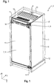
- Fig. 1 shows a representation of a household refrigerator 1, in the form of a refrigerator, comprising a household appliance device according to the invention 2.
- the household appliance device 2 comprises a body 3 and a pivotally arranged on the body by means of two bearing elements 4 closure element 5.
- the bearing elements 4 are each formed by multi-hinge hinges 6.
- the household refrigerator 1 is arranged in a furniture recess 12, which is shown transparent for illustrative purposes. If the closure element 5 from the in FIG. 1 shown, closed position is brought into an open position, this leads to the body 3 thus both a rotational movement and a translational movement.
- the closure element 5 is formed in this case by a door 7.
- Within the body 3 is an unillustrated storage space for receiving refrigerated goods, which is accessible through the door 7.
- Both the body 3 and the door 7 have cavities which are filled with thermal insulation material.
- the body 3 has as outer lining side walls 8, a cover element 9, a bottom element and a rear wall 10. Between this outer lining and an inner container, not shown, there is a cavity which is filled with the thermal insulation material.
- the door 7 has an outer wall 13 and an inner wall facing the storage space in the closed position of the door 7. Between the outer wall 13 and the inner wall is a cavity which is filled with the thermal insulation material.
- the door 7 has a fastening means 15 for fastening a plate-like decorative element, for example a furniture panel. Those portions of the fastening means 15, which are arranged on a narrow side 11 of the door 7, but a cover 16 are substantially covered.
- conduit 17 extends between the body 3 and the door 7.
- the conduit 17 is fastened both to the body 3 and to the door 7.
- the line 17 emerges from a forwardly facing front side of the body 3 and occurs on the upper narrow side 11 of the door 7 below the cover 16 in the door 7 a.
- Fig. 2 shows a section of a front view of the household refrigerator Fig. 1 , the upper portion, wherein for illustration purposes, the cover member 16 is shown transparently.
- the spring element 18 is formed by a line section 17 'of the line 17, in particular by the shape of the line 17.
- the line 17 has a helical shape or helical shape.
- the individual helix form spring sections 19.
- the helical shape or helical form extends over the entire line 17, ie, the line section 17 'substantially corresponds to the entire line 17.
- the line 17 is stretched relative to the closed position of the door 7, so the slope of the helix or helix increases and the line 17 has a tensile stress.
- the line 17 has at both end portions plug elements 20, with which the line 17 is releasably secured on the one hand on the upper narrow side 11 of the door 7 and on the other hand on an end face of the body 3.
- Fig. 3 shows sections of a second embodiment.
- Fig. 3a shows an upper section of a front view of a household refrigerator 1 according to the invention, wherein the door 7 is in the closed position.
- Fig. 3b shows a perspective view of the door 7 in the open position.
- the cover 16 is shown transparent for illustrative purposes.
- the spring element 18 is formed by a spring mechanism 21.
- the spring mechanism 21 comprises a roller 22, which is tensioned by a (not shown) spring.
- a portion 17 "of the conduit portion 17 ' is rolled up on the roller 22.
- the roller 22 is rotatably fixed to the door 7, with an axis of rotation of the roller 22 being fixedly arranged with respect to the door 7.
- FIG Fig. 1 shows an upper section of a front view of a household refrigerator 1 according to the invention, wherein the door 7 is in the closed position.
- Fig. 3b shows a perspective view of the door 7 in the open position.
- the cover 16 is shown transparent for
- Fig. 4 shows sections of a third embodiment with too Fig. 3 comparable views.
- the spring element 18 is in turn formed by a spring mechanism 21.
- the spring mechanism 21 comprises two springs 23, namely coil springs.
- Each spring 23 has a stationary relative to the door 7 end portion 23a and a resilient, ie free, end portion 23b.
- the stationary end portions 23a are fixed to the cover 16 in this embodiment.
- a guide member 24 is arranged in each case.
- Each guide member 24 has a groove in which portions 17 "" of the conduit portion 17 'is received. The grooves are dimensioned such that the portions 17 "" can slide through the grooves with little friction.
- the portions 17 "" formed by means of the springs 23 forces to curved sections.
- the line section 17 'thus has a tensile stress.
- the springs 23 When opening the door 7, in particular if it performs a translational movement relative to the body 3, the springs 23 are compressed. If the door 7 from the in Fig. 4b As shown in the open position shown, the spring force of the springs 33 ensures that the sections 17 "" are again formed into curved sections.
- Fig. 5 shows sections of a fourth embodiment with too Fig. 3 comparable views while in Fig. 6 a perspective section of this embodiment is shown.
- the spring element 18 is in turn formed by a spring mechanism 21.
- the spring mechanism 21 comprises a spring 23, in the form of a helical spring, with a stationary end 23a and a resilient end 23b.
- the fixed end 23 a is fixed to an abutment 25 on the door 7.
- the spring mechanism 21 further comprises a roller 26 and a roller bearing 27, within which the roller 26 is rotatably mounted.
- the roller bearing 27 is arranged displaceably against a force generated by the spring 23.
- a guide carriage 28 is arranged on the roller bearing 27, which can move within a slide guide 29.
- the household refrigerator 1 further comprises a line deflection 30. This serves a change of direction over the Conduction lead 30 guided line 17 so that the line 17 is guided in the desired direction in the spring mechanism 21.
- Fig. 7 shows a section of a fifth embodiment with a to Fig. 3a comparable view, that is, in a closed position of the door 7.
- a further line deflection 30 is arranged on the door 7.
- the conduit deflection 30 is formed by a roller, whose lateral surface has a groove to guide the conduit 17.
- This line deflection 30 makes it possible to guide the line 17 in a widthwise central portion of the door 7.
- the line 17 can thus enter centrally in the door 7 substantially in the width direction X, so that a Mosanschlag lymph can easily be done without the connection of the line 17 with the door 7, a plug connection would be necessary.
Landscapes
- Engineering & Computer Science (AREA)
- Chemical & Material Sciences (AREA)
- Combustion & Propulsion (AREA)
- Physics & Mathematics (AREA)
- Mechanical Engineering (AREA)
- Thermal Sciences (AREA)
- General Engineering & Computer Science (AREA)
- Closing And Opening Devices For Wings, And Checks For Wings (AREA)
- Refrigerator Housings (AREA)
Abstract
Description
- Die Erfindung betrifft eine Haushaltsgerätevorrichtung mit einem Korpus und einem daran zwischen einer geschlossenen Stellung und einer geöffneten Stellung beweglich angeordneten Verschlusselement sowie mit einer sowohl am Korpus als auch an dem Verschlusselement angeordneten Leitung.
- Eine solche Haushaltsgerätevorrichtung kann insbesondere Teil eines Kältegerätes sein. Bei Kältegeräten, insbesondere Haushaltskältegeräten wie Kühlschränken, Gefrierschränken oder Kühl-Gefrier-Kombinationen, kann das Verschlusselement eine Bedieneinheit und/oder Anzeigeeinheit zur Steuerung von Funktionen und Anzeige von Betriebszuständen des Kältegerätes aufweisen. Denkbar ist auch, dass das Verschlusselement einen Eisspender und/oder einen Wasserspender aufweist. In solchen Fällen besteht die Notwendigkeit, eine elektrische Leitung oder eine Wasserleitung von dem Korpus in das Verschlusselement zu führen.
- Aus der
DE 10 2008 026 709 A1 ist eine Anordnung zur Führung eines Kabels von einem Korpus eines Möbelelementes oder Gerätes zu einem Verschlusselement bekannt, wobei die Anordnung ein Gehäuse aufweist, in dem ein Abschnitt des Kabels verläuft, sodass dieser Abschnitt verdeckt oder geschützt werden soll. - Der vorliegenden Erfindung liegt die Aufgabe zugrunde, eine eingangs genannte Haushaltsgerätevorrichtung bereitzustellen, welche eine sichere und langlebige Führung der Leitung zwischen dem Korpus und dem Verschlusselement ermöglicht.
- Die Aufgabe wird dadurch gelöst, dass die Haushaltsgerätevorrichtung ein Federelement umfasst, welches zumindest auf einen Leitungsabschnitt der Leitung in zumindest der geöffneten Stellung des Verschlusselements eine Zugspannung ausübt.
- Die Zugspannung wirkt als Rückstellkraft auf den Leitungsabschnitt. Der Leitungsabschnitt hat somit in der geöffneten Stellung des Verschlusselements das Bestreben wieder in seinen ursprünglichen Zustand zurückzukehren. Diese Zugspannung erlaubt es somit, eine ausreichende Länge der Leitung vorzusehen, ohne dass die Gefahr besteht, dass Abschnitte der Leitung eine unerwünschte bzw. unkontrollierte Gestalt annehmen, zum Beispiel Durchhängen.
- Das Verschlusselement kann durch eine Türe, eine Klappe oder eine Schubladenfront gebildet sein. In der geöffneten Stellung wird ein Innenbereich des Korpus, zum Beispiel ein Lagerraum für zu kühlendes oder zu gefrierendes Gut, abhängig von dem Öffnungswinkel teilweise oder vollständig für einen Benutzer zugänglich. Das Verschlusselement kann eine in der geschlossenen Stellung dem Korpus zugewandte Innenwandung eine dem Korpus abgewandte Außenwandung aufweisen. Die Innenwandung und die Außenwand können einen mit thermischen Isolationsmaterial gefüllten Hohlraum begrenzen.
- Die Leitung kann beispielsweise durch eine elektrische Leitung, eine Datenleitung oder durch eine Wasserleitung gebildet sein. Möglich ist auch, dass die Leitung innerhalb einer äußeren Ummantelung sowohl eine oder mehrere elektrische Leitung(en) und/oder Datenleitungen und/oder eine oder mehrere Wasserleitung(en) umfasst.
- Ausführungsformen der Erfindung sind in den abhängigen Ansprüchen angegeben.
- Gemäß einer Ausführungsform ist vorgesehen, dass das Federelement auf den Leitungsabschnitt in der geschlossenen Stellung des Verschlusselements eine Zugspannung ausübt. Der Leitungsabschnitt steht somit sowohl in der geöffneten Stellung als auch in der geschlossenen Stellung unter einer Zugspannung. In diesem Fall kann auch in der geschlossenen Stellung des Verschlusselements sichergestellt werden, dass der Leitungsabschnitt keine unerwünschte Gestalt annimmt, insbesondere nicht durchhängt. Somit resultiert eine präzise und damit sichere Führung der Leitung zwischen dem Korpus und dem Verschlusselement. Grundsätzlich denkbar wäre, dass die auf den Leitungsabschnitt in dem geschlossenen Zustand und dem geöffneten Zustand des Verschlusselements ausgeübte Zugkraft (im Wesentlichen) gleich groß ist. Eine einfache Ausgestaltung wird jedoch gemäß einer Ausführungsform dadurch erreicht, dass die Zugspannung des Leitungsabschnitts in der geöffneten Stellung des Verschlusselements größer ist als die Zugspannung des Leitungsabschnitts in der geschlossenen Stellung des Verschlusselements. Insbesondere kann vorgesehen sein, dass sich die Zugspannung beim Öffnen des Verschlusselements bis in eine maximale geöffnete Stellung des Verschlusselements kontinuierlich, zum Beispiel linear bezüglich eines Öffnungswinkels, erhöht.
- Gemäß einer Ausführungsform ist vorgesehen, dass die Zugspannung des Leitungsabschnitts in der geöffneten Stellung des Verschlusselements durch eine elastische Verformung des Leitungsabschnitts erzeugt wird. Zwar kann bei dieser Ausführungsform auch ein bezüglich der Leitung separater, zusätzlicher Federmechanismus vorgesehen sein. Grundsätzlich kann jedoch vorgesehen sein, dass die komplette auf den Leitungsabschnitt ausgeübte Zugspannung ausschließlich durch die elastische Verformung des Leitungsabschnitts selbst erzeugt wird. Auf diese Weise resultiert eine einfache und dennoch wirksame Lösung der Aufgabe. Die elastische Verformung könnte durch eine Streckung des Leitungsabschnitts entlang seiner Längsachse erfolgen. Eine solche Ausführungsform wäre insbesondere für eine Wasserleitung denkbar, die im Wesentlichen lediglich aus einem elastischen Leitungsmantel besteht. Gemäß einer Ausführungsform ist jedoch vorgesehen, dass das Federelement durch in dem Leitungsabschnitt ausgebildete Federabschnitte gebildet ist. Dieser Ausführungsform kann beispielsweise für elektrische Leitungen und Datenleitungen eingesetzt werden. Insbesondere ermöglicht diese Ausführungsform eine elastische Verformung des Leitungsabschnitts ohne eine Streckung des selbigen entlang seiner Längsachse. Die Federabschnitte können insbesondere derart ausgestaltet sein, dass die elastische Verformung, vorzugsweise ausschließlich, durch eine Biegeverformung erzeugt wird. Gemäß einer Ausführungsform ist vorgesehen, dass die Federabschnitte durch eine Wendelform bzw. Helixform des Leitungsabschnitts gebildet sind. Möglich ist, dass die komplette Leitung, gegebenenfalls mit Ausnahme der beiden Endabschnitte der Leitung, eine Wendelform aufweist. Die Erzeugung der Zugspannung durch die elastische Verformung des Leitungsabschnitts erfolgt durch eine Vergrößerung der Steigung des Wendel bzw der Steigung der Helix.
- Zusätzlich oder alternativ kann gemäß einer Ausführungsform vorgesehen sein, dass das Federelement durch einen bezüglich der Leitung separaten Federmechanismus gebildet ist. Ein separater Federmechanismus erlaubt eine anwendungsspezifisch und präzise einstellbare Zugspannung. Zwar wäre es grundsätzlich denkbar, einen mehrteiligen Federmechanismus teilweise an bzw. innerhalb des Korpus und an bzw. innerhalb des Verschlusselements anzuordnen. Um einen kompakten Aufbau zu erreichen, kann jedoch vorgesehen sein, den Federmechanismus ausschließlich an bzw. innerhalb des Korpus oder an bzw. innerhalb Verschlusselements anzuordnen.
- Gemäß einer Ausführungsform ist vorgesehen, dass der Federmechanismus ein Element zum Aufrollen eines Abschnitts des Leitungsabschnitts aufweist. Insbesondere kann vorgesehen sein, dass die Länge eines in der geschlossenen Stellung des Verschlusselements auf das Element aufgerollten Abschnitts größer ist als die Länge eines in der geöffneten Stellung des Verschlusselements auf das Element aufgerollten Abschnitts. Gemäß einer Ausführungsform ist vorgesehen dass das Element durch eine an dem Korpus oder an dem Verschlusselement drehbar angeordnete und durch eine Feder spannbare Rolle gebildet ist. Eine Drehachse der Rolle kann bezüglich derjenigen Baueinheit von Korpus und Verschlusselement, an welcher die Rolle angeordnet ist, ortsfest angeordnet sein. Die Rolle kann durch eine Drehfeder spannbar sein.
- Gemäß einer Ausführungsform ist vorgesehen, dass der Federmechanismus einen Abschnitt des Leitungsabschnitts in der geschlossenen Stellung des Verschlusselements mittels einer durch eine Feder erzeugten Kraft zu einem gekrümmten Abschnitt ausformt. Der gekrümmte Abschnitt kann insbesondere eine Schlaufe oder einen Bogen bilden. Dabei kann der Federmechanismus den gekrümmten Abschnitt mittels der Feder direkt ausformen bzw. auslenken. Um Reibungswiderstände zu minimieren, kann jedoch vorgesehen sein, dass der Federmechanismus ein Führungselement aufweist, welches den gekrümmten Abschnitt ausformt. Das Führungselement kann insbesondere eine Führungsnut aufweisen. Der gekrümmte Abschnitt kann mit Spiel in der Führungsnut geführt werden. Das Führungselement kann insbesondere ortsfest bezüglich eines federnden Endabschnitts der Feder angeordnet sein. Beispielsweise kann das Führungselement durch eine an einem federnden Endabschnitt der Feder montierte Führungskappe gebildet sein. Denkbar ist jedoch auch, dass das Führungselement zur weiteren Minimierung der Reibung durch eine Rollenführung gebildet ist. So ist gemäß einer Ausführungsform gesehen, dass der Federmechanismus eine an dem Korpus oder an dem Verschlusselement drehbar angeordnete Rolle aufweist, die entgegen der durch die Feder erzeugten Federkraft verschiebbar angeordnet ist. Die Rolle kann auf ihrer Mantelfläche eine Führungsnut aufweisen.
- Gemäß einer Ausführungsform ist vorgesehen, dass der Federmechanismus komplett an dem Verschlusselement angeordnet ist. Der Federmechanismus kann insbesondere an einem Endabschnitt des Verschlusselements angeordnet sein. Beispielsweise kann der Federmechanismus an einem oberen oder unteren Endabschnitt angeordnet sein. Diese Ausgestaltung erlaubt einen einfachen Türanschlagswechsel, da der Federmechanismus leicht zugänglich und somit leicht demontierbar und erneut in Breitenrichtung spiegelverkehrt montierbar ist
- Die Haushaltsgerätevorrichtung kann ein Abdeckelement zum teilweisen oder vollständigen Abdecken des Federmechanismus aufweisen. Gemäß einer Ausführungsform ist vorgesehen, dass das Verschlusselement ein Befestigungsmittel für ein, insbesondere plattenförmiges, Dekorelement sowie ein Abdeckelement zum teilweisen oder vollständigen Abdecken des Befestigungsmittels aufweist und dass das Abdeckelement den Federmechanismus teilweise oder vollständig abdeckt.
- Gemäß einer Ausführungsform ist vorgesehen, dass die Haushaltsgerätevorrichtung eine Leitungsumlenkung umfasst, insbesondere eine Umlenkrolle, welche eine Richtungsänderung der über die Leitungsumlenkung geführten Leitung bewirkt. Die Leitungsumlenkung ermöglicht es, die Leitung gezielt zu gewünschten Verbindungsstellen an dem Korpus bzw. dem Verschlusselement zu führen. Vorzugsweise weist die Leitungsumlenkung eine Nut zum Führen der Leitung auf.
- Gemäß einer Ausführungsform ist vorgesehen, dass das Federelement durch eine Relativbewegung des Verschlusselements gegenüber dem Korpus beim Öffnen des Verschlusselements spannbar ist bzw. gespannt wird. Insbesondere kann vorgesehen sein, dass das Federelement ausschließlich durch diese Relativbewegung spannbar ist bzw. gespannt wird.
- Der Korpus und das Verschlusselement können durch ein oder mehrere Lagerelemente, zum Beispiel Scharniere oder Auszugsschienen (Teleskopschienen), miteinander verbunden sein. Das oder die Lagerelemente ermöglichen eine Verstellung des Verschlusselements zwischen der geschlossenen Stellung der geöffneten Stellung. Der Korpus und das Verschlusselement können insbesondere mittels eines, mittels zweier oder mittels mehrerer Mehrgelenksscharniere miteinander verbunden sein. Ein Mehrgelenkscharnier zeichnet sich dadurch aus, dass dieses sowohl eine Rotation als auch eine Translationsbewegung zwischen dem Korpus und dem Verschlusselement ermöglicht.
- Gemäß einer Ausführungsform ist vorgesehen, dass die Leitung mittels einer, insbesondere lösbaren, Steckverbindung an dem Korpus und/oder an dem Verschlusselement befestigt ist. Auf diese Weise wird ein einfach zu bewerkstelligender Türanschlagswechsel ermöglicht.
- Gemäß einer Ausführungsform ist vorgesehen, dass die Haushaltsgerätevorrichtung ein Kältegerät ist und vorzugsweise das Verschlusselement eine Tür ist. Denkbar ist, dass das Kältegerät zwei oder mehrere Verschlusselemente bzw. Türen aufweist und zwei oder mehrere Leitungen von dem Korpus erfindungsgemäß in die Verschlusselement bzw. Türen geführt sind.
- Mit Angaben "oben", "unten", "vorne", "hinten, "horizontal", "vertikal", "Tiefenrichtung", "Breitenrichtung", "Höhenrichtung" etc. sind die bei bestimmungsgemäßen Gebrauch und bestimmungsgemäßem Anordnen der Haushaltsgerätevorrichtung bzw. des Kältegeräts und bei einem dann vor der Haushaltsgerätevorrichtung bzw. dem Kältegerät stehenden und in Richtung der Haushaltsgerätevorrichtung bzw. des Kältegeräts blickenden Beobachter gegebenen Positionen und Orientierungen angegeben.
- Ausführungsbeispiele der vorliegenden Erfindung werden anhand der beigefügten Figuren erläutert. Dabei zeigen:
- Fig. 1
- eine schematische Darstellung eines erfindungsgemäßen Haushaltskältegerätes gemäß einem ersten Ausführungsbeispiel,
- Fig. 2
- einen Ausschnitt einer Frontansicht des Haushaltskältegeräts aus
Fig. 1 , - Fig. 3
- Ausschnitte eines zweiten Ausführungsbeispiels,
- Fig. 4
- Ausschnitte eines dritten Ausführungsbeispiels,
- Fig. 5
- Ausschnitte eines vierten Ausführungsbeispiels,
- Fig. 6
- ein perspektivischer Ausschnitt des vierten Ausführungsbeispiels und
- Fig. 7
- einen Ausschnitt eines fünften Ausführungsbeispiels.
- Gleiche oder funktionsgleiche Elemente sind im Folgenden mit den gleichen Bezugszeichen versehen.
-
Fig. 1 zeigt eine Darstellung eines Haushaltskältegerätes 1, in Form eines Kühlschrankes, umfassend eine erfindungsgemäße Haushaltsgerätevorrichtung 2. Die Haushaltsgerätevorrichtung 2 umfasst einen Korpus 3 sowie ein an dem Korpus mittels zweier Lagerelemente 4 schwenkbar angeordnetes Verschlusselement 5. Die Lagerelemente 4 sind jeweils durch Mehrgelenksscharniere 6 gebildet. Das Haushaltskältegerät 1 ist in einer Möbelnische 12 angeordnet, die zu Illustrationszwecken transparent dargestellt ist. Sofern das Verschlusselement 5 aus der inFigur 1 gezeigten, geschlossenen Stellung in eine geöffnete Stellung gebracht wird, führt dieses gegenüber dem Korpus 3 somit sowohl eine Rotationsbewegung als auch eine Translationsbewegung aus. Das Verschlusselement 5 ist in diesem Fall durch eine Tür 7 gebildet. Innerhalb des Korpus 3 befindet sich ein nicht dargestellter Lagerraum zur Aufnahme von Kühlgut, der durch die Tür 7 zugänglich ist. Sowohl der Korpus 3 als auch die Tür 7 weisen Hohlräume auf, die mit thermischem Isolationsmaterial gefüllt sind. Der Korpus 3 weist als Außenverkleidung Seitenwände 8, ein Deckelement 9, ein Bodenelement sowie eine Rückwand 10 auf. Zwischen dieser Außenverkleidung und einem nicht dargestellten Innenbehälter befindet sich ein Hohlraum, der mit dem thermischen Isolationsmaterial gefüllt ist. Die Tür 7 weist eine Außenwand 13 sowie eine in der geschlossenen Stellung der Tür 7 dem Lagerraum zugewandte Innenwand auf. Zwischen der Außenwand 13 und der Innenwand befindet sich ein Hohlraum der mit dem thermischen Isolationsmaterial gefüllt ist. Die Tür 7 weist ein Befestigungsmittel 15 zur Befestigung eines plattenartigen Dekorelements, zum Beispiel einer Möbelplatte, auf. Jene Abschnitte des Befestigungsmittel 15, welche auf einer Schmalseite 11 der Tür 7 angeordnet sind, sind doch ein Abdeckelement 16 im Wesentlichen abgedeckt. Zwischen dem Korpus 3 und der Tür 7 verläuft eine Leitung 17. Die Leitung 17 ist sowohl am Korpus 3 als auch an der Tür 7 befestigt. Die Leitung 17 tritt aus einer nach vorne gewandten Stirnseite des Korpus 3 aus und tritt auf der oberen Schmalseite 11 der Tür 7 unterhalb des Abdeckelements 16 in die Tür 7 ein. -
Fig. 2 zeigt einen Ausschnitt einer Frontansicht des Haushaltskältegeräts ausFig. 1 , nämlich den oberen Abschnitt, wobei zu Illustrationszwecken das Abdeckelement 16 transparent dargestellt ist. In diesem Ausführungsbeispiel ist das Federelement 18 durch einen Leitungsabschnitt 17' der Leitung 17 gebildet, insbesondere durch die Formgebung der Leitung 17. Die Leitung 17 weist eine Wendelform oder Helixform auf. Die einzelnen Wendel bilden dabei Federabschnitte 19 aus. In diesem Ausführungsbeispiel erstreckt sich die Wendelform bzw. Helixform über die komplette Leitung 17, d.h. der Leitungsabschnitt 17' entspricht im Wesentlichen der kompletten Leitung 17. In der geöffneten Stellung der Tür 7 ist die Leitung 17 gegenüber der geschlossenen Stellung der Tür 7 gestreckt, sodass sich die Steigung des Wendel bzw. des Helix vergrößert und die Leitung 17 eine Zugspannung aufweist. Die Leitung 17 weist an beiden Endabschnitten Steckerelemente 20 auf, mit denen die Leitung 17 einerseits auf der oberen Schmalseite 11 der Tür 7 und andererseits auf einer Stirnseite des Korpus 3 lösbar befestigt ist. -
Fig. 3 zeigt Ausschnitte eines zweiten Ausführungsbeispiels.Fig. 3a zeigt einen oberen Ausschnitt einer Vorderansicht eines erfindungsgemäßen Haushaltskältegeräts 1, wobei sich die Tür 7 in der geschlossenen Stellung befindet.Fig. 3b zeigt eine perspektivische Darstellung der Tür 7 in der geöffneten Stellung. In beiden Darstellungen ist das Abdeckelement 16 Aus Illustrationszwecken transparent dargestellt. Das Federelement 18 ist durch einen Federmechanismus 21 gebildet. Der Federmechanismus 21 umfasst eine Rolle 22, die durch eine (nicht dargestellte) Feder spannbar ist. Auf der Rolle 22 ist ein Abschnitt 17"des Leitungsabschnitts 17' aufgerollt. Die Rolle 22 ist an der Tür 7 drehbar festgelegt, wobei eine Drehachse der Rolle 22 ortsfest bezüglich der Tür 7 angeordnet ist. In der inFig. 3a dargestellten geschlossenen Stellung der Tür 7 umfasst der Abschnitt 17" mehrere Wicklungen der Leitung 17. Beim Öffnen der Tür 7, insbesondere wenn die Tür 7 gegenüber dem Korpus 3 translatorisch bewegt wird, beginnen sich diese Wicklungen entgegen der durch die Feder bewirkten Kraft abzuwickeln, sodass die Feder weiter gespannt wird. Zumindest in der geöffneten Stellung der Tür 7 wirkt auf den Leitungsabschnitt 17' (rechts von dem Federmechanismus 21) eine Zugspannung. Beim Schließen der Tür 7 sorgt die Zugspannung dafür, dass die Leitung 17 wieder teilweise auf die Rolle 22 aufgewickelt wird. -
Fig. 4 zeigt Ausschnitte eines dritten Ausführungsbeispiels mit zuFig. 3 vergleichbaren Ansichten. Das Federelement 18 ist wiederum durch einen Federmechanismus 21 gebildet. Der Federmechanismus 21 umfasst zwei Federn 23, nämlich Schraubenfedern. - Jede Feder 23 weist einen bezüglich der Tür 7 ortsfesten Endabschnitt 23a und einen federnden, also freien, Endabschnitt 23b auf. Die ortsfesten Endabschnitte 23a sind in diesem Ausführungsbeispiel an dem Abdeckelement 16 festgelegt. An den federnden Endabschnitten 23b ist jeweils ein Führungselement 24 angeordnet. Jedes Führungselement 24 weist eine Nut auf, in welcher Abschnitte 17"" des Leitungsabschnitts 17' aufgenommen ist. Dabei sind die Nuten derart bemessen, dass die Abschnitte 17"" mit geringer Reibung durch die Nuten gleiten können. In der in
Fig. 4a dargestellten geschlossenen Stellung der Tür 7 werden die Abschnitte 17"" mittels durch die Federn 23 erzeugte Kräfte zu gekrümmten Abschnitten ausgeformt. Der Leitungsabschnitt 17' weist somit eine Zugspannung auf. Beim Öffnen der Tür 7, insbesondere sofern diese gegenüber dem Korpus 3 eine Translationsbewegung ausführt, werden die Federn 23 komprimiert. Sofern die Tür 7 aus der inFig. 4b gezeigten geöffneten Stellung geschlossen wird, sorgt die Federkraft der Federn 33 dafür, dass die Abschnitte 17"" erneut in gekrümmte Abschnitte geformt werden. -
Fig. 5 zeigt Ausschnitte eines vierten Ausführungsbeispiels mit zuFig. 3 vergleichbaren Ansichten, während inFig. 6 ein perspektivischer Ausschnitt dieses Ausführungsbeispiels gezeigt ist. Das Federelement 18 ist wiederum durch einen Federmechanismus 21 gebildet. Der Federmechanismus 21 umfasst eine Feder 23, in Form einer Schraubenfeder, mit einem ortsfesten Ende 23a sowie einem federnden Ende 23b. Das ortsfeste Ende 23a ist an einem Widerlager 25 an der Tür 7 festgelegt. Der Federmechanismus 21 umfasst weiterhin eine Rolle 26 sowie eine Rollenlagerung 27, innerhalb der die Rolle 26 drehbar gelagert ist. Die Rollenlagerung 27 ist entgegen einer durch die Feder 23 erzeugten Kraft verschiebbar angeordnet. Dazu ist an der Rollenlagerung 27 ein Führungsschlitten 28 angeordnet, der innerhalb einer Schlittenführung 29 verfahren kann. Das federnde Ende 23b der Feder 23 kontaktiert den Führungsschlitten 28. Sobald die Tür aus der inFig. 5a gezeigten geschlossenen Stellung geöffnet wird, beginnt der Führungsschlitten 28 entgegen der durch die Feder 23 erzeugten Kraft diese zu komprimieren d.h. der Führungsschlitten 28 verfährt entlang der Schlittenführung 29 nach rechts. Der Leitungsabschnitt 17' rollt dabei über die Rolle 26 ab. Zumindest in der inFig. 5b gezeigten geöffneten Stellung der Tür ist die Feder 23 komprimiert, sodass auf den Leitungsabschnitt 17' eine Zugspannung wirkt. Wie insbesondere inFig. 6 zu erkennen ist, weist das Haushaltskältegerät 1 weiterhin eine Leitungsumlenkung 30 auf. Diese dient dazu eine Richtungsänderung der über die Leitungsumlenkung 30 geführten Leitung 17 zu bewirken, sodass die Leitung 17 in der gewünschten Richtung in den Federmechanismus 21 geführt wird. -
Fig. 7 zeigt einen Ausschnitt eines fünften Ausführungsbeispiels mit einer zuFig. 3a vergleichbaren Ansicht, das heißt in einer geschlossenen Stellung der Tür 7. Im Gegensatz zum vierten Ausführungsbeispiel ist an der Tür 7 eine weitere Leitungsumlenkung 30 angeordnet. Die Leitungsumlenkung 30 ist durch eine Rolle gebildet, deren Mantelfläche eine Nut aufweist, um die Leitung 17 zu führen. Diese Leitungsumlenkung 30 ermöglicht es, die Leitung 17 in einen in Breitenrichtung X mittigen Abschnitt der Tür 7 zu führen. Die Leitung 17 kann somit im Wesentlichen in Breitenrichtung X mittig in die Tür 7 eintreten, sodass ein Türanschlagswechsel einfach erfolgen kann, ohne dass zur Verbindung der Leitung 17 mit der Tür 7 eine Steckverbindung notwendig wäre.BEZUGSZEICHENLISTE 1 Haushaltskältegerät 21 Federmechanismus 2 Haushaltsgerätevorrichtung 22 Rolle 3 Korpus 23 Feder 4 Lagerelement 23a ortsfester Endabschnitt 5 Verschlusselement 23b federnder Endabschnitt 6 Mehrgelenkscharnier 24 Führungselement 7 Tür 25 Widerlager 8 Seitenwand 26 Rolle 9 Deckelement 27 Rollenlagerung 10 Rückwand 28 Führungsschlitten 11 Schmalseite 29 Schlittenführung 12 Möbelnische 30 Leitungsumlenkung 13 Außenwand 15 Befestigungsmittel 16 Abdeckelement 17 Leitung 17' Leitungsabschnitt 17" Abschnitt 17'" Abschnitt 17"" Abschnitt 18 Federelement 19 Federabschnitt 20 Steckerelement
Claims (15)
- Haushaltsgerätevorrichtung (2) mit einem Korpus (3) und einem daran zwischen einer geschlossenen Stellung und einer geöffneten Stellung beweglich angeordneten Verschlusselement (5) zum Verschließen eines im Korpus (3) befindlichen Lagerraumes sowie mit einer sowohl am Korpus (3) als auch an dem Verschlusselement (5) angeordneten Leitung (17), gekennzeichnet durch ein Federelement (18), welches zumindest auf einen Leitungsabschnitt (17') der Leitung (17) in zumindest der geöffneten Stellung des Verschlusselements (5) eine Zugspannung ausübt.
- Haushaltsgerätevorrichtung (2) nach Anspruch 1, dadurch gekennzeichnet, dass das Federelement () auf den Leitungsabschnitt () in der geschlossenen Stellung des Verschlusselements (5) eine Zugspannung ausübt.
- Haushaltsgerätevorrichtung (2) nach Anspruch 2, dadurch gekennzeichnet, dass die Zugspannung des Leitungsabschnitts in der geöffneten Stellung des Verschlusselements (5) größer ist als die Zugspannung des Leitungsabschnitts in der geschlossenen Stellung des Verschlusselements (5).
- Haushaltsgerätevorrichtung (2) nach einem der vorhergehenden Ansprüche, dadurch gekennzeichnet, dass die Zugspannung des Leitungsabschnitts in der geöffneten Stellung des Verschlusselements (5) durch eine elastische Verformung des Leitungsabschnitts erzeugt wird.
- Haushaltsgerätevorrichtung (2) nach Anspruch 4, dadurch gekennzeichnet, dass das Federelement (18) durch in dem Leitungsabschnitt (17) ausgebildete Federabschnitte (19) gebildet ist.
- Haushaltsgerätevorrichtung (2) nach Anspruch 5, dadurch gekennzeichnet, dass die Federabschnitte (19) durch eine Wendelform des Leitungsabschnitts (17') gebildet sind.
- Haushaltsgerätevorrichtung (2) nach einem der vorhergehenden Ansprüche, dadurch gekennzeichnet, dass das Federelement (18) durch einen bezüglich der Leitung (17) separaten Federmechanismus (21) gebildet ist.
- Haushaltsgerätevorrichtung (2) nach Anspruch 7, dadurch gekennzeichnet, dass der Federmechanismus (21) ein Element zum Aufrollen eines Abschnitts (17") des Leitungsabschnitts (17') aufweist.
- Haushaltsgerätevorrichtung (2) nach Anspruch 8, dadurch gekennzeichnet, dass das Element durch eine an dem Korpus (3) oder an dem Verschlusselement (5) drehbar angeordnete und durch eine Feder spannbare Rolle (22) gebildet ist.
- Haushaltsgerätevorrichtung (2) nach Anspruch 7, dadurch gekennzeichnet, dass der Federmechanismus (21) einen Abschnitt des Leitungsabschnittes (17') in der geschlossenen Stellung des Verschlusselements (5) mittels einer durch eine Feder (23) erzeugten Federkraft zu einem gekrümmten Abschnitt (17"") ausformt.
- Haushaltsgerätevorrichtung (2) nach Anspruch 10, dadurch gekennzeichnet, dass der Federmechanismus (21) eine an dem Korpus (3) oder an dem Verschlusselement (5) drehbar angeordnete Rolle (26) aufweist, die entgegen einer durch eine Feder (23) erzeugten Federkraft verschiebbar angeordnet ist.
- Haushaltsgerätevorrichtung (2) nach einem der vorhergehenden Ansprüche, gekennzeichnet durch zumindest eine Leitungsumlenkung (30), insbesondere eine Umlenkrolle, welche eine Richtungsänderung der über die Leitungsumlenkung (30) geführten Leitung (17) bewirkt.
- Haushaltsgerätevorrichtung (2) nach einem der vorhergehenden Ansprüche, dadurch gekennzeichnet, dass das Federelement (18) durch eine Relativbewegung des Verschlusselements (5) gegenüber dem Korpus (3) beim Öffnen des Verschlusselements (5) spannbar ist bzw. gespannt wird.
- Haushaltsgerätevorrichtung (2) nach einem der vorhergehenden Ansprüche, dadurch gekennzeichnet, dass die Leitung (17) mittels einer, insbesondere lösbaren, Steckverbindung an dem Korpus (3) und/oder dem Verschlusselement (5) befestigt ist.
- Haushaltskältegerät (1), umfassend eine Haushaltsgerätevorrichtung (2) nach einem der vorhergehenden Ansprüche.
Priority Applications (1)
| Application Number | Priority Date | Filing Date | Title |
|---|---|---|---|
| PL18160484T PL3379181T3 (pl) | 2017-03-22 | 2018-03-07 | Przyrząd urządzenia gospodarstwa domowego z korpusem, z elementem zamykającym oraz z przewodem zamocowanym na korpusie i na elemencie zamykającym |
Applications Claiming Priority (1)
| Application Number | Priority Date | Filing Date | Title |
|---|---|---|---|
| DE102017204820.4A DE102017204820A1 (de) | 2017-03-22 | 2017-03-22 | Haushaltsgerätevorrichtung mit einem Korpus, einem Verschlusselement sowie einer an dem Korpus und an dem Verschlusselement befestigten Leitung |
Publications (2)
| Publication Number | Publication Date |
|---|---|
| EP3379181A1 true EP3379181A1 (de) | 2018-09-26 |
| EP3379181B1 EP3379181B1 (de) | 2022-03-02 |
Family
ID=61598934
Family Applications (1)
| Application Number | Title | Priority Date | Filing Date |
|---|---|---|---|
| EP18160484.4A Active EP3379181B1 (de) | 2017-03-22 | 2018-03-07 | Haushaltsgerätevorrichtung mit einem korpus, einem verschlusselement sowie einer an dem korpus und an dem verschlusselement befestigten leitung |
Country Status (3)
| Country | Link |
|---|---|
| EP (1) | EP3379181B1 (de) |
| DE (1) | DE102017204820A1 (de) |
| PL (1) | PL3379181T3 (de) |
Cited By (2)
| Publication number | Priority date | Publication date | Assignee | Title |
|---|---|---|---|---|
| WO2023046448A1 (de) * | 2021-09-23 | 2023-03-30 | BSH Hausgeräte GmbH | Haushaltsgerätevorrichtung, haushaltsgerät und verfahren zur montage und/oder zum betrieb einer haushaltsgerätevorrichtung |
| EP4517185A1 (de) * | 2023-08-29 | 2025-03-05 | LG Electronics Inc. | Tür für ein haushaltsgerät |
Families Citing this family (1)
| Publication number | Priority date | Publication date | Assignee | Title |
|---|---|---|---|---|
| DE102021210627A1 (de) | 2021-09-23 | 2023-03-23 | BSH Hausgeräte GmbH | Haushaltsgerätevorrichtung, Haushaltsgerät und Verfahren zur Montage und/oder zum Betrieb einer Haushaltsgerätevorrichtung |
Citations (7)
| Publication number | Priority date | Publication date | Assignee | Title |
|---|---|---|---|---|
| US3788094A (en) * | 1972-12-01 | 1974-01-29 | Gen Motors Corp | Waterline retractor for refrigerator cabinet |
| US20060087207A1 (en) * | 2004-10-26 | 2006-04-27 | Lg Electronics Inc. | Refrigerator |
| US20060087208A1 (en) * | 2004-10-26 | 2006-04-27 | Lg Electronics Inc. | Refrigerator |
| DE102008026709A1 (de) | 2007-06-09 | 2008-12-11 | Liebherr-Hausgeräte Ochsenhausen GmbH | Kühl- und/oder Gefriergerät |
| WO2011080236A1 (en) * | 2009-12-31 | 2011-07-07 | Arcelik Anonim Sirketi | A built-in dishwasher comprising a decorative panel on the door thereof |
| KR20110088360A (ko) * | 2010-01-28 | 2011-08-03 | 삼성전자주식회사 | 냉장고 |
| US20140319990A1 (en) * | 2013-04-29 | 2014-10-30 | Whirlpool Corporation | Appliance with closure element having an operative device |
-
2017
- 2017-03-22 DE DE102017204820.4A patent/DE102017204820A1/de not_active Withdrawn
-
2018
- 2018-03-07 EP EP18160484.4A patent/EP3379181B1/de active Active
- 2018-03-07 PL PL18160484T patent/PL3379181T3/pl unknown
Patent Citations (7)
| Publication number | Priority date | Publication date | Assignee | Title |
|---|---|---|---|---|
| US3788094A (en) * | 1972-12-01 | 1974-01-29 | Gen Motors Corp | Waterline retractor for refrigerator cabinet |
| US20060087207A1 (en) * | 2004-10-26 | 2006-04-27 | Lg Electronics Inc. | Refrigerator |
| US20060087208A1 (en) * | 2004-10-26 | 2006-04-27 | Lg Electronics Inc. | Refrigerator |
| DE102008026709A1 (de) | 2007-06-09 | 2008-12-11 | Liebherr-Hausgeräte Ochsenhausen GmbH | Kühl- und/oder Gefriergerät |
| WO2011080236A1 (en) * | 2009-12-31 | 2011-07-07 | Arcelik Anonim Sirketi | A built-in dishwasher comprising a decorative panel on the door thereof |
| KR20110088360A (ko) * | 2010-01-28 | 2011-08-03 | 삼성전자주식회사 | 냉장고 |
| US20140319990A1 (en) * | 2013-04-29 | 2014-10-30 | Whirlpool Corporation | Appliance with closure element having an operative device |
Cited By (2)
| Publication number | Priority date | Publication date | Assignee | Title |
|---|---|---|---|---|
| WO2023046448A1 (de) * | 2021-09-23 | 2023-03-30 | BSH Hausgeräte GmbH | Haushaltsgerätevorrichtung, haushaltsgerät und verfahren zur montage und/oder zum betrieb einer haushaltsgerätevorrichtung |
| EP4517185A1 (de) * | 2023-08-29 | 2025-03-05 | LG Electronics Inc. | Tür für ein haushaltsgerät |
Also Published As
| Publication number | Publication date |
|---|---|
| PL3379181T3 (pl) | 2022-05-09 |
| EP3379181B1 (de) | 2022-03-02 |
| DE102017204820A1 (de) | 2018-09-27 |
Similar Documents
| Publication | Publication Date | Title |
|---|---|---|
| EP2250929B1 (de) | Schrankteil mit herausziehbarem Ausziehteil | |
| EP2827741B1 (de) | Zuziehvorrichtung für ein beweglich gelagertes möbelteil | |
| DE102012103629A1 (de) | Schlepptürbeschlag | |
| AT509923A1 (de) | Einzugsvorrichtung zum einziehen eines bewegbar gelagerten möbelteiles | |
| DE112013004458T5 (de) | Kühlschrank mit einer Schiebetür | |
| DE202007005957U1 (de) | Kühl- und/oder Gefriergerät | |
| EP2314962A2 (de) | Haushaltsgerät | |
| DE102013114309A1 (de) | Einzugs- und Dämpfungseinheit für ein Schiebeelement | |
| EP3589159A1 (de) | SCHRANKMÖBEL ODER HAUSHALTSGERÄT UND VERFAHREN ZUM ÖFFNEN UND SCHLIEßEN EINES SCHRANKMÖBELS ODER HAUSHALTSGERÄTES | |
| EP3379181B1 (de) | Haushaltsgerätevorrichtung mit einem korpus, einem verschlusselement sowie einer an dem korpus und an dem verschlusselement befestigten leitung | |
| DE102008021344A1 (de) | Haushaltsgerät | |
| EP2281095B1 (de) | Haushaltsgerät | |
| EP3420167B1 (de) | Stellarmantrieb | |
| EP3379180B1 (de) | Haushaltsgerätevorrichtung mit einem korpus, einem verschlusselement sowie einer an dem korpus und an dem verschlusselement befestigten leitung | |
| EP2283196A1 (de) | Scharnierelement und gehäuse für ein haushaltsgerät | |
| EP3068266B1 (de) | Möbelantrieb | |
| EP1957902B1 (de) | Kältegerät mit einer fluidleitfähigen türanbindung | |
| EP2274492B1 (de) | Haushaltsgerät | |
| DE102017204821A1 (de) | Haushaltsgerätevorrichtung mit einem Korpus, einem Verschlusselement sowie einer an dem Korpus und an dem Verschlusselement befestigten Leitung | |
| EP2283195B1 (de) | Scharnierelement und gehäuse für ein haushaltsgerät | |
| DE102013103820B4 (de) | Kühlgerät | |
| DE102016122594A1 (de) | Kühlgerät und Öffnungssystem für ein Kühlgerät | |
| DE3239041C2 (de) | ||
| EP2267384B1 (de) | Gerätetür mit Türanbindung | |
| AT517591A4 (de) | Stellantrieb für Möbelteile |
Legal Events
| Date | Code | Title | Description |
|---|---|---|---|
| PUAI | Public reference made under article 153(3) epc to a published international application that has entered the european phase |
Free format text: ORIGINAL CODE: 0009012 |
|
| STAA | Information on the status of an ep patent application or granted ep patent |
Free format text: STATUS: THE APPLICATION HAS BEEN PUBLISHED |
|
| AK | Designated contracting states |
Kind code of ref document: A1 Designated state(s): AL AT BE BG CH CY CZ DE DK EE ES FI FR GB GR HR HU IE IS IT LI LT LU LV MC MK MT NL NO PL PT RO RS SE SI SK SM TR |
|
| AX | Request for extension of the european patent |
Extension state: BA ME |
|
| STAA | Information on the status of an ep patent application or granted ep patent |
Free format text: STATUS: REQUEST FOR EXAMINATION WAS MADE |
|
| 17P | Request for examination filed |
Effective date: 20190326 |
|
| RBV | Designated contracting states (corrected) |
Designated state(s): AL AT BE BG CH CY CZ DE DK EE ES FI FR GB GR HR HU IE IS IT LI LT LU LV MC MK MT NL NO PL PT RO RS SE SI SK SM TR |
|
| STAA | Information on the status of an ep patent application or granted ep patent |
Free format text: STATUS: EXAMINATION IS IN PROGRESS |
|
| 17Q | First examination report despatched |
Effective date: 20191205 |
|
| GRAP | Despatch of communication of intention to grant a patent |
Free format text: ORIGINAL CODE: EPIDOSNIGR1 |
|
| STAA | Information on the status of an ep patent application or granted ep patent |
Free format text: STATUS: GRANT OF PATENT IS INTENDED |
|
| INTG | Intention to grant announced |
Effective date: 20211018 |
|
| GRAS | Grant fee paid |
Free format text: ORIGINAL CODE: EPIDOSNIGR3 |
|
| GRAA | (expected) grant |
Free format text: ORIGINAL CODE: 0009210 |
|
| STAA | Information on the status of an ep patent application or granted ep patent |
Free format text: STATUS: THE PATENT HAS BEEN GRANTED |
|
| AK | Designated contracting states |
Kind code of ref document: B1 Designated state(s): AL AT BE BG CH CY CZ DE DK EE ES FI FR GB GR HR HU IE IS IT LI LT LU LV MC MK MT NL NO PL PT RO RS SE SI SK SM TR |
|
| REG | Reference to a national code |
Ref country code: GB Ref legal event code: FG4D Free format text: NOT ENGLISH |
|
| REG | Reference to a national code |
Ref country code: CH Ref legal event code: EP Ref country code: AT Ref legal event code: REF Ref document number: 1472563 Country of ref document: AT Kind code of ref document: T Effective date: 20220315 |
|
| REG | Reference to a national code |
Ref country code: DE Ref legal event code: R096 Ref document number: 502018008897 Country of ref document: DE |
|
| REG | Reference to a national code |
Ref country code: IE Ref legal event code: FG4D Free format text: LANGUAGE OF EP DOCUMENT: GERMAN |
|
| REG | Reference to a national code |
Ref country code: LT Ref legal event code: MG9D |
|
| REG | Reference to a national code |
Ref country code: NL Ref legal event code: MP Effective date: 20220302 |
|
| PG25 | Lapsed in a contracting state [announced via postgrant information from national office to epo] |
Ref country code: SE Free format text: LAPSE BECAUSE OF FAILURE TO SUBMIT A TRANSLATION OF THE DESCRIPTION OR TO PAY THE FEE WITHIN THE PRESCRIBED TIME-LIMIT Effective date: 20220302 Ref country code: RS Free format text: LAPSE BECAUSE OF FAILURE TO SUBMIT A TRANSLATION OF THE DESCRIPTION OR TO PAY THE FEE WITHIN THE PRESCRIBED TIME-LIMIT Effective date: 20220302 Ref country code: NO Free format text: LAPSE BECAUSE OF FAILURE TO SUBMIT A TRANSLATION OF THE DESCRIPTION OR TO PAY THE FEE WITHIN THE PRESCRIBED TIME-LIMIT Effective date: 20220602 Ref country code: LT Free format text: LAPSE BECAUSE OF FAILURE TO SUBMIT A TRANSLATION OF THE DESCRIPTION OR TO PAY THE FEE WITHIN THE PRESCRIBED TIME-LIMIT Effective date: 20220302 Ref country code: HR Free format text: LAPSE BECAUSE OF FAILURE TO SUBMIT A TRANSLATION OF THE DESCRIPTION OR TO PAY THE FEE WITHIN THE PRESCRIBED TIME-LIMIT Effective date: 20220302 Ref country code: ES Free format text: LAPSE BECAUSE OF FAILURE TO SUBMIT A TRANSLATION OF THE DESCRIPTION OR TO PAY THE FEE WITHIN THE PRESCRIBED TIME-LIMIT Effective date: 20220302 Ref country code: BG Free format text: LAPSE BECAUSE OF FAILURE TO SUBMIT A TRANSLATION OF THE DESCRIPTION OR TO PAY THE FEE WITHIN THE PRESCRIBED TIME-LIMIT Effective date: 20220602 |
|
| PG25 | Lapsed in a contracting state [announced via postgrant information from national office to epo] |
Ref country code: LV Free format text: LAPSE BECAUSE OF FAILURE TO SUBMIT A TRANSLATION OF THE DESCRIPTION OR TO PAY THE FEE WITHIN THE PRESCRIBED TIME-LIMIT Effective date: 20220302 Ref country code: GR Free format text: LAPSE BECAUSE OF FAILURE TO SUBMIT A TRANSLATION OF THE DESCRIPTION OR TO PAY THE FEE WITHIN THE PRESCRIBED TIME-LIMIT Effective date: 20220603 Ref country code: FI Free format text: LAPSE BECAUSE OF FAILURE TO SUBMIT A TRANSLATION OF THE DESCRIPTION OR TO PAY THE FEE WITHIN THE PRESCRIBED TIME-LIMIT Effective date: 20220302 |
|
| PG25 | Lapsed in a contracting state [announced via postgrant information from national office to epo] |
Ref country code: NL Free format text: LAPSE BECAUSE OF FAILURE TO SUBMIT A TRANSLATION OF THE DESCRIPTION OR TO PAY THE FEE WITHIN THE PRESCRIBED TIME-LIMIT Effective date: 20220302 |
|
| PG25 | Lapsed in a contracting state [announced via postgrant information from national office to epo] |
Ref country code: SM Free format text: LAPSE BECAUSE OF FAILURE TO SUBMIT A TRANSLATION OF THE DESCRIPTION OR TO PAY THE FEE WITHIN THE PRESCRIBED TIME-LIMIT Effective date: 20220302 Ref country code: SK Free format text: LAPSE BECAUSE OF FAILURE TO SUBMIT A TRANSLATION OF THE DESCRIPTION OR TO PAY THE FEE WITHIN THE PRESCRIBED TIME-LIMIT Effective date: 20220302 Ref country code: RO Free format text: LAPSE BECAUSE OF FAILURE TO SUBMIT A TRANSLATION OF THE DESCRIPTION OR TO PAY THE FEE WITHIN THE PRESCRIBED TIME-LIMIT Effective date: 20220302 Ref country code: PT Free format text: LAPSE BECAUSE OF FAILURE TO SUBMIT A TRANSLATION OF THE DESCRIPTION OR TO PAY THE FEE WITHIN THE PRESCRIBED TIME-LIMIT Effective date: 20220704 Ref country code: EE Free format text: LAPSE BECAUSE OF FAILURE TO SUBMIT A TRANSLATION OF THE DESCRIPTION OR TO PAY THE FEE WITHIN THE PRESCRIBED TIME-LIMIT Effective date: 20220302 Ref country code: CZ Free format text: LAPSE BECAUSE OF FAILURE TO SUBMIT A TRANSLATION OF THE DESCRIPTION OR TO PAY THE FEE WITHIN THE PRESCRIBED TIME-LIMIT Effective date: 20220302 |
|
| REG | Reference to a national code |
Ref country code: CH Ref legal event code: PL |
|
| PG25 | Lapsed in a contracting state [announced via postgrant information from national office to epo] |
Ref country code: IS Free format text: LAPSE BECAUSE OF FAILURE TO SUBMIT A TRANSLATION OF THE DESCRIPTION OR TO PAY THE FEE WITHIN THE PRESCRIBED TIME-LIMIT Effective date: 20220702 Ref country code: AL Free format text: LAPSE BECAUSE OF FAILURE TO SUBMIT A TRANSLATION OF THE DESCRIPTION OR TO PAY THE FEE WITHIN THE PRESCRIBED TIME-LIMIT Effective date: 20220302 |
|
| REG | Reference to a national code |
Ref country code: DE Ref legal event code: R097 Ref document number: 502018008897 Country of ref document: DE |
|
| REG | Reference to a national code |
Ref country code: BE Ref legal event code: MM Effective date: 20220331 |
|
| PLBE | No opposition filed within time limit |
Free format text: ORIGINAL CODE: 0009261 |
|
| STAA | Information on the status of an ep patent application or granted ep patent |
Free format text: STATUS: NO OPPOSITION FILED WITHIN TIME LIMIT |
|
| PG25 | Lapsed in a contracting state [announced via postgrant information from national office to epo] |
Ref country code: MC Free format text: LAPSE BECAUSE OF FAILURE TO SUBMIT A TRANSLATION OF THE DESCRIPTION OR TO PAY THE FEE WITHIN THE PRESCRIBED TIME-LIMIT Effective date: 20220302 Ref country code: LU Free format text: LAPSE BECAUSE OF NON-PAYMENT OF DUE FEES Effective date: 20220307 Ref country code: LI Free format text: LAPSE BECAUSE OF NON-PAYMENT OF DUE FEES Effective date: 20220331 Ref country code: IE Free format text: LAPSE BECAUSE OF NON-PAYMENT OF DUE FEES Effective date: 20220307 Ref country code: FR Free format text: LAPSE BECAUSE OF NON-PAYMENT OF DUE FEES Effective date: 20220502 Ref country code: DK Free format text: LAPSE BECAUSE OF FAILURE TO SUBMIT A TRANSLATION OF THE DESCRIPTION OR TO PAY THE FEE WITHIN THE PRESCRIBED TIME-LIMIT Effective date: 20220302 Ref country code: CH Free format text: LAPSE BECAUSE OF NON-PAYMENT OF DUE FEES Effective date: 20220331 |
|
| 26N | No opposition filed |
Effective date: 20221205 |
|
| PG25 | Lapsed in a contracting state [announced via postgrant information from national office to epo] |
Ref country code: SI Free format text: LAPSE BECAUSE OF FAILURE TO SUBMIT A TRANSLATION OF THE DESCRIPTION OR TO PAY THE FEE WITHIN THE PRESCRIBED TIME-LIMIT Effective date: 20220302 Ref country code: BE Free format text: LAPSE BECAUSE OF NON-PAYMENT OF DUE FEES Effective date: 20220331 |
|
| GBPC | Gb: european patent ceased through non-payment of renewal fee |
Effective date: 20220602 |
|
| PG25 | Lapsed in a contracting state [announced via postgrant information from national office to epo] |
Ref country code: GB Free format text: LAPSE BECAUSE OF NON-PAYMENT OF DUE FEES Effective date: 20220602 |
|
| PGFP | Annual fee paid to national office [announced via postgrant information from national office to epo] |
Ref country code: TR Payment date: 20230306 Year of fee payment: 6 Ref country code: PL Payment date: 20230224 Year of fee payment: 6 |
|
| PGFP | Annual fee paid to national office [announced via postgrant information from national office to epo] |
Ref country code: IT Payment date: 20230331 Year of fee payment: 6 |
|
| PG25 | Lapsed in a contracting state [announced via postgrant information from national office to epo] |
Ref country code: HU Free format text: LAPSE BECAUSE OF FAILURE TO SUBMIT A TRANSLATION OF THE DESCRIPTION OR TO PAY THE FEE WITHIN THE PRESCRIBED TIME-LIMIT; INVALID AB INITIO Effective date: 20180307 |
|
| PG25 | Lapsed in a contracting state [announced via postgrant information from national office to epo] |
Ref country code: MK Free format text: LAPSE BECAUSE OF FAILURE TO SUBMIT A TRANSLATION OF THE DESCRIPTION OR TO PAY THE FEE WITHIN THE PRESCRIBED TIME-LIMIT Effective date: 20220302 Ref country code: CY Free format text: LAPSE BECAUSE OF FAILURE TO SUBMIT A TRANSLATION OF THE DESCRIPTION OR TO PAY THE FEE WITHIN THE PRESCRIBED TIME-LIMIT Effective date: 20220302 |
|
| REG | Reference to a national code |
Ref country code: AT Ref legal event code: MM01 Ref document number: 1472563 Country of ref document: AT Kind code of ref document: T Effective date: 20230307 |
|
| PG25 | Lapsed in a contracting state [announced via postgrant information from national office to epo] |
Ref country code: AT Free format text: LAPSE BECAUSE OF NON-PAYMENT OF DUE FEES Effective date: 20230307 |
|
| PG25 | Lapsed in a contracting state [announced via postgrant information from national office to epo] |
Ref country code: AT Free format text: LAPSE BECAUSE OF NON-PAYMENT OF DUE FEES Effective date: 20230307 |
|
| PG25 | Lapsed in a contracting state [announced via postgrant information from national office to epo] |
Ref country code: MT Free format text: LAPSE BECAUSE OF FAILURE TO SUBMIT A TRANSLATION OF THE DESCRIPTION OR TO PAY THE FEE WITHIN THE PRESCRIBED TIME-LIMIT Effective date: 20220302 |
|
| PG25 | Lapsed in a contracting state [announced via postgrant information from national office to epo] |
Ref country code: IT Free format text: LAPSE BECAUSE OF NON-PAYMENT OF DUE FEES Effective date: 20240307 |
|
| PG25 | Lapsed in a contracting state [announced via postgrant information from national office to epo] |
Ref country code: PL Free format text: LAPSE BECAUSE OF NON-PAYMENT OF DUE FEES Effective date: 20240307 |
|
| PGFP | Annual fee paid to national office [announced via postgrant information from national office to epo] |
Ref country code: DE Payment date: 20260331 Year of fee payment: 9 |
|
| PGFP | Annual fee paid to national office [announced via postgrant information from national office to epo] |
Ref country code: AT Payment date: 20260410 Year of fee payment: 5 |