EP3379180B1 - Haushaltsgerätevorrichtung mit einem korpus, einem verschlusselement sowie einer an dem korpus und an dem verschlusselement befestigten leitung - Google Patents
Haushaltsgerätevorrichtung mit einem korpus, einem verschlusselement sowie einer an dem korpus und an dem verschlusselement befestigten leitung Download PDFInfo
- Publication number
- EP3379180B1 EP3379180B1 EP18160433.1A EP18160433A EP3379180B1 EP 3379180 B1 EP3379180 B1 EP 3379180B1 EP 18160433 A EP18160433 A EP 18160433A EP 3379180 B1 EP3379180 B1 EP 3379180B1
- Authority
- EP
- European Patent Office
- Prior art keywords
- line
- housing
- carcass
- household refrigerator
- closing element
- Prior art date
- Legal status (The legal status is an assumption and is not a legal conclusion. Google has not performed a legal analysis and makes no representation as to the accuracy of the status listed.)
- Active
Links
Images


Classifications
-
- F—MECHANICAL ENGINEERING; LIGHTING; HEATING; WEAPONS; BLASTING
- F25—REFRIGERATION OR COOLING; COMBINED HEATING AND REFRIGERATION SYSTEMS; HEAT PUMP SYSTEMS; MANUFACTURE OR STORAGE OF ICE; LIQUEFACTION SOLIDIFICATION OF GASES
- F25D—REFRIGERATORS; COLD ROOMS; ICE-BOXES; COOLING OR FREEZING APPARATUS NOT OTHERWISE PROVIDED FOR
- F25D23/00—General constructional features
- F25D23/02—Doors; Covers
- F25D23/028—Details
-
- F—MECHANICAL ENGINEERING; LIGHTING; HEATING; WEAPONS; BLASTING
- F25—REFRIGERATION OR COOLING; COMBINED HEATING AND REFRIGERATION SYSTEMS; HEAT PUMP SYSTEMS; MANUFACTURE OR STORAGE OF ICE; LIQUEFACTION SOLIDIFICATION OF GASES
- F25D—REFRIGERATORS; COLD ROOMS; ICE-BOXES; COOLING OR FREEZING APPARATUS NOT OTHERWISE PROVIDED FOR
- F25D2400/00—General features of, or devices for refrigerators, cold rooms, ice-boxes, or for cooling or freezing apparatus not covered by any other subclass
- F25D2400/40—Refrigerating devices characterised by electrical wiring
Definitions
- the invention relates to a household refrigeration device with a body and a closure element movably arranged thereon between a closed position and an open position for closing a storage space located in the body and with a line attached to both the body and the closure element, and with a line housing in which in the closed position of the closure element at least one line section is arranged.
- Such a household appliance device can in particular be part of a refrigeration device.
- the closure element can have an operating unit and / or display unit for controlling functions and displaying operating states of the refrigeration device. It is also conceivable that the closure element has an ice dispenser and / or a water dispenser. In such cases it is necessary to lead an electrical line and / or a water line from the body into the closure element.
- US 2011/005264 A1 discloses a refrigeration device with a pull-out with a chain unit which are coupled to one another in order to allow rotation, the pull-out and the chain unit providing a cable chain to cover a line.
- US 2014/319990 A1 discloses a device with a receptacle and a first closure element for closing at least one area of an access opening of the receptacle and with a second closure element which is formed relative to the first closure element and which is coupled to an operating unit, wherein a line is led through the first closure element into the second closure element.
- U.S. 3,788,094 A discloses a refrigeration device with a cold water usage area on an outer area of a door, comprising a water line which leads from a cold water tank within a body to a dispensing valve in the cold water usage area, a retraction mechanism for the water line being attached to a side wall of the body.
- DE 693 23 392 T2 discloses a cooling device comprising a housing and a door and a compartment mounted under the housing and a device which forms a guide tunnel for a pipeline.
- the present invention is based on the object of providing a household appliance device mentioned at the outset which enables the line to be guided reliably and for a long time between the body and the closure element.
- the line housing thus serves as a receiving space for part of the line section which is not required when the closure element is closed, but is required when the closure element is open so that the line is guided from the body to the closure element without (elastic) stretching of the line.
- the line can be at least partially pulled out of the line housing when the closure element is opened, preferably exclusively by the opening movement of the closure element itself.
- the extracted section of the line section can be moved back into the line housing, likewise preferably exclusively by the movement of the closure element itself .
- the closure element can be formed by a door, a flap or a drawer front. In the open position, an inner area of the body, in particular the storage space for items to be cooled or frozen, is partially or completely accessible to a user, depending on the opening angle.
- the closure element can have an inner wall facing the body in the closed position and an outer wall facing away from the body. The inner wall and the outer wall can delimit a cavity filled with thermal insulation material.
- the line can be formed, for example, by an electrical line, a data line or a water line. It is also possible for the line to include both one or more electrical line (s) and / or data lines and / or one or more water line (s) within an outer jacket.
- the line housing is arranged on an outer wall of the body or of the closure element.
- the line housing can be arranged in a non-destructive detachable manner, for example by means of a force-fit and / or form-fit connection. In particular, latching and / or screwing is possible.
- the closure element is a door
- this embodiment allows a simple and inexpensive door hinge change by first having the cable housing done by a fitter can be dismantled and then mounted in another position on the body or door. It is conceivable that the line housing is arranged on a cover element of the body.
- the line housing is at least partially, preferably completely, arranged within the body or the closure element.
- this enables a relatively large cable housing to be integrated into the household appliance device, so that the cable can be guided in large radii within the gold cable. This minimizes the risk of a line break.
- the line housing can be positioned in such a way that the line can be guided in the transition area between the body and the closure element without small radii as possible.
- the line housing can be arranged in a space between an outer wall and an inner wall of the body or of the closure element. A wall or a wall section of the line housing can delimit a cavity filled with thermal insulation material.
- the line housing is arranged on the body or within the body and has a line through-opening that is open to the front.
- the line passage opening faces a rear wall of the closure element, in particular in the closed position of the closure element.
- the rear wall represents a wall facing the body, which in particular partially delimits the storage space in the closed position of the closure element.
- the line can exit forward unhindered through the line passage opening when opened and enter the line housing again when closed. Since the line passage opening is open to the front, the line can be pulled out sufficiently and without increased force when the closure element is opened, in particular when the closure element executes not only a rotary but also a translational movement.
- the line passage opening can be formed in a cover of the line housing or at least partially delimited by a cover of the line housing.
- the line housing is arranged on the body or within the body and that the line housing is arranged essentially flush with a front surface of the body.
- the cable housing thus does not protrude forward over the body. This not only enables a compact arrangement of the line housing within the household appliance device. Rather, it is also possible to guide the line into the closure element, which allows relatively large radii of the line.
- two cable housings are arranged on the body or within the body, preferably in the width direction on two opposite end sections of the body. Only one of the two line housings can have the line section according to the invention. The other line housing serves to accommodate the line section when the door hinge is changed. One of the two line housings can be completely closed by a cover.
- the line housing is arranged, preferably centrally in the width direction, in an upper or lower end section of the closure element. If the line housing is arranged in an upper end section, the line housing preferably has a line passage opening that is open upward in the vertical direction. If the cable housing is arranged in a lower end section, the cable housing preferably has a cable passage opening that is open downward in the vertical direction.
- a line housing arranged centrally in the closure element enables a door stop change in a particularly simple manner. In particular, it can be provided that the household appliance device has only a single cable housing.
- the body and the closure element can be connected to one another by one or more bearing elements, for example hinges or pull-out rails (telescopic rails).
- the bearing element or elements enable the closure element to be adjusted between the closed position and the open position.
- the body and the closure element can in particular be connected to one another by means of one, two or more multi-joint hinges.
- a multi-joint hinge is characterized by the fact that it can rotate as well as also allows a translational movement between the body and the closure element.
- the line housing is arranged in the vicinity of a bearing element.
- a close range is to be understood here as meaning that the smallest possible distance between the cable housing and the bearing element is less than 10 cm, preferably less than 5 cm, more preferably less than 3 cm, preferably less than 1 cm.
- a line passage opening of the line housing is arranged in the vicinity of a bearing element.
- this enables relatively inconspicuous guidance of the line between the body and the closure element in a simple manner.
- the line can be supported indirectly and / or directly by the bearing element.
- a surface of the bearing element can serve as a support surface. A relative movement between the support surface of the bearing element and the section of the line that has fallen thereon is conceivable.
- the household appliance device has a line return device for returning the line section into the line housing when the closure element is closed.
- the line return device can in particular comprise a spring element.
- the spring element can have a greater prestress in the open position of the closure element than in the closed position of the closure element.
- the spring element can in particular be formed by a component separate from the line.
- the spring element can be formed, for example, by a helical spring.
- the closure element has a fastening means for a, in particular plate-shaped, decorative element and a cover element for partially or completely covering the fastening means and that the cover element has a holding element and / or a guide element for holding and / or guiding the line.
- the holding element can in particular be designed to ensure a non-positive and / or positive holding of the line.
- a holding element can, for example, by two opposing Locking lugs be formed, the line being clipped between the locking lugs.
- a retaining element can also be formed by a groove that receives the line essentially without play.
- a guide element can be formed by a groove that essentially takes up the line with play.
- a guide element can also be formed by a guide surface contacting the line.
- the guide surface can be flat or curved; in particular, a curvature of the guide surface can predetermine a minimum bending radius of the line.
- Several holding elements and / or guide elements can be provided on the cover element. It is conceivable that the holding element or elements or guide elements are formed in one piece with the cover element.
- the cover element can consist of plastic.
- the household appliance device comprises a bearing element, in particular a hinge or a pull-out rail, as well as a holding element and / or guide element arranged on the bearing element for holding and / or guiding the line.
- the holding element or guide element can basically be designed to be functionally identical, in particular structurally identical, to the holding element or guide element arranged on the cover.
- the holding element or the guide element is a separate component with respect to the bearing element.
- the holding element or guide element can consist of plastic or metal.
- the line is fastened to the body and / or to the closure element by means of a, in particular detachable, plug connection.
- a plug connection for attaching the cable. This plug connection is thus protected against external influences.
- At least one movable section of the line which moves relative to the body and / or the closure element when the closure element is opened or closed, has an additional casing.
- the additional sheathing reduces the likelihood of damage to the line due to frequent opening and closing of the Closure element.
- the line is protected from damage caused by direct intervention by a user.
- the additional sheathing can consist of plastic or metal.
- the additional sheathing consists partially or completely of a textile material.
- the additional sheathing can be at least partially formed by a fabric.
- the additional sheathing is only provided on one section with respect to the length of the line.
- the line it is also conceivable for the line to have an additional sheathing along its entire length.
- the additional sheathing specifies a minimum bending radius for the line.
- the additional cladding thus prevents the line from assuming a smaller bending radius than the minimum bending radius defined by the additional cladding.
- the additional sheathing can have several or a multiplicity of chain links.
- the additional sheathing is preferably fastened exclusively to the line and / or arranged in a stationary manner relative to a section of the line.
- the household appliance device has a decorative element attached to the closure element.
- the decorative element is preferably designed in a plate shape.
- the decorative element is formed by a furniture panel.
- the decorative element protrudes in a height direction (i.e. vertically) and / or in a width direction (i.e. horizontally) over end sections of the closure element and covers the cable housing forwards at least in the closed position of the closure element. In this case, the cable housing is not visible to a user standing in front of the household appliance device.
- a sensor for example a door opening sensor
- a door opening mechanism or components of a door opening mechanism for automatically opening the closure element are arranged in the line housing.
- the cable housing can consist partially or completely of plastic.
- the cable housing can have a cover for closing the section by section Have line housing.
- a line passage opening can preferably be provided in the cover. It is conceivable that the line housing is made in one piece.
- the line housing can have a substantially cuboid shape.
- the cable housing can be constructed in several parts.
- the line housing can have a, for example trough-shaped, base element which can be closed with a cover element. Both the base element and the cover element can be arranged, preferably completely, within the body or within the closure element. It is conceivable that either the base element and / or the cover element is formed by a wall of the body or of the closure element, e.g. a cover element of the body. However, it is also conceivable that both the base element and the cover element are separate components with respect to the wall of the body and the closure element. It is conceivable that the base element and / or the cover element are formed in one piece with an electronics housing. A division of the line housing into a base element and a cover element enables easier (initial) assembly of the line or a plug element for the line, since the accessibility, in particular to a rear section of the line housing, is improved.
- a single line housing in which there is a line section - at least in the closed position of the closure element - is basically sufficient.
- the household appliance device has several, for example two, line housings, in each of which a line section is located in the closed position of the closing element.
- a first cable housing can be arranged on or in the body, while a second cable housing can be arranged on or in the closure element.
- the household appliance device is a refrigerator and preferably the closure element is a door.
- the closure element or the door can be connected to the body via two multi-joint hinges. It is conceivable that the refrigeration device has two or more closure elements or doors and two or more lines are guided according to the invention from the body into the closure elements or doors.
- Fig. 1 shows a representation of a household refrigerator 1, in the form of a refrigerator, comprising a household appliance device 2 according to the invention.
- the household appliance device 2 comprises a body 3 and a closure element 5 pivotably arranged on the body by means of two bearing elements 4.
- the bearing elements 4 are each formed by multi-joint hinges 6.
- the household refrigerator 1 is arranged in a furniture niche xxx, which is shown as transparent for illustration purposes. If the closure element 5 from the in Fig. 1 The closed position shown is brought into an open position, this therefore performs both a rotational movement and a translational movement with respect to the body 3.
- the closure element 5 is formed by a door 7 in this case.
- Both the body 3 and the door 7 have between outer walls and inner walls cavities which are filled with thermal insulation material.
- the body 3 has side walls 8, a cover element 9, a base element and a rear wall 10 (see FIG Fig. 2 ) on. Between this outer wall and an inner container 11 as the inner wall there is a cavity 12 which is filled with the thermal insulation material.
- the door 7 has an outer wall 13 and an inner wall 14 facing the storage room in the closed position of the door 7 in the sense of a rear wall. Between the outer wall 13 and the inner wall 14 there is a cavity which is filled with the thermal insulation material.
- the door 7 has a fastening means 15 for fastening a plate-like decorative element, for example a furniture panel. Those sections of the fastening means 15 which are arranged on a narrow side of the door 7 are essentially covered by a cover element 16.
- a line 17 runs between the body 3 and the door 7. The line 17 is attached both to the body 3 and to the door 7. The line 17 emerges from a line housing 18 from the body 3, runs along an upper narrow side of the door 7 and enters the door 7 on the upper narrow side.
- the cable housing 18 is arranged both in the width direction X and in the height direction Z on an edge section of the body. The cable housing 18 is arranged completely within the body. In this case, the line housing 18 does not protrude beyond a front surface 39 of the body 3, ie a front section of the line housing 18 runs flush with the front surface 39.
- FIG. 2 shows two schematic representations of top views of the household refrigerator from FIG Fig. 1 , the cover element 9 having been omitted for purposes of illustration.
- Fig. 2a the door 7 shown in the closed position while Figure 2b shows the door 7 in the open position.
- a line section 17 'of the line 17 is located inside the line housing 18.
- the line section 17' forms here a U-shaped loop.
- the line 17 is partially pulled out of the line housing 18.
- the length of the line section 17 'still remaining in the line housing 18 is smaller than the length of the line section 17' located in the line housing 18 in the closed position of the door 7.
- the line 17 is pulled out of the line housing 18 by opening the door 7 or tracked, so that there is no undesirable increase in a tensile force on the line when the door 7 is opened. In particular, the line 17 is not stretched when the door 7 is opened.
- Two cable housings 18 are arranged in the body. These are located in the width direction X at opposite end sections. A line section 17 'is only located in that (right) line housing 18 which is arranged in the vicinity of the hinge 6. The other (left) line housing 18 serves to accommodate a line section 17 'of line 17 when the door hinge is changed.
- Each line housing 18 has a line feed section 19.
- the line 17 can be guided from the body 3 into the line housing 18 by means of the line feed section 19.
- the line 17 is guided from an electronics housing 38 into the line housing 18 by means of the line feed section 19. It would also be conceivable to route the line 17 directly from the cavity 12 into the line housing 18 by means of the line feed section 19.
- Each line feed section 19 has a plug element 20 which is connected to a corresponding plug element 21 of the line section 17 'and forms a plug connection (right line housing 18) or can be connected (left line housing 18).
- Each line housing 18 has a line passage opening 22 which is open towards the front and through which the line 17 emerges from the line housing 18 and thus from the body 3.
- the line passage opening 22 of the left line housing 18 is completely closed by a cover 23 which can be removed when the door is changed.
- the right line housing 18 has a cover 28 which partially closes an assembly opening 29 so that only the line passage opening 22 remains open.
- the assembly opening 29 allows the line 17 to be stowed within the line housing 18 during the manufacture of the household refrigeration appliance.
- the line 17 emerging from the line passage opening 22 runs above the hinge 6 along a narrow side 23 of the door 7.
- the door has an entry opening 24 in the width direction, through which the line enters the door 7.
- the inlet opening 24 has a plug element 25 which forms a plug connection with a corresponding plug element 26 of the line 17.
- the plug connections in the cable housing 18 or on the door 7 enable simple assembly and disassembly in the event of a repair.
- the line 17 has an additional sheathing 30.
- the additional sheathing 30 is arranged on only a section of the line 17.
- the additional cladding 30 is fixedly arranged on the line 17; in particular, the additional cladding 30 does not move with respect to the line 17 when the door 7 is opened or closed.
- the additional cladding 30 is formed by a drag chain, the chain links of which allow the line 17 to bend. At the same time, however, a minimum bending radius of the line 17 is predetermined by the additional sheathing 30.
- Fig. 4 shows one to Fig. 3 comparable section of a second embodiment.
- the cover element 16 has holding elements 31.
- the holding elements 31 are formed in one piece with the cover element 16.
- the holding elements 31 each form a groove that receives the line 17 essentially without play. In that the line 17 can be pressed into the groove from above, simple assembly is made possible, especially when the door hinge is possibly changed.
- the cover element 16 also has a guide element 32, which is also formed in one piece with the cover element 16.
- the guide element 32 is formed by a section of a cylinder jacket surface and serves to guide the line 17, which initially runs horizontally over the cover element 16, vertically into the door 7. A minimum bending radius is also specified here by means of the specified curvature of the guide element 32.
- Fig. 5 shows one to Fig. 3 comparable section of a third embodiment.
- the hinge 6 here has a holding element 33 arranged thereon.
- the holding element 33 is a component which is formed separately with respect to the hinge 6 and which is subsequently attached to the hinge 6.
- the holding element 33 ensures that the line 17 is held in the vertical direction Z at a predetermined height. An undesired contact of the line with the hinge 6, in particular a dragging of the line 17 along a surface of the hinge 6, is thereby prevented.
- Fig. 6 shows a detail of a plan view similar to FIG Fig. 2 of a fourth embodiment.
- the household refrigerator has a line return device 34 for returning the line section 17 'into the line housing 18 when the door 7 is closed.
- the line return device 34 comprises a spring element 35 which is arranged such that it is (further) tensioned when the door 7 is opened. In the open position of the door 7, the spring element 35 exerts a restoring force on the line section 17 ′, so that it is safely and reliably pulled back into the line housing 18 when the door 7 is closed.
- the line return device 34 furthermore has a guide roller 36. When the door 7 is opened, the line section 17 ′ can roll over the guide roller 36, so that despite the line return device 34, only a small additional resistance arises.
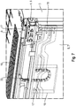
- Fig. 7 shows a section of a fifth embodiment.
- the body 3 does not have a cable housing. Rather, a line housing 18 is arranged in the door 7.
- the line housing 18 has an upwardly open line passage opening 22 through which the line section 17 'is guided when the door 7 is opened.
- the line 17 is fastened on the one hand by means of a plug connection in the cable housing 18 and on the other hand fastened to the body 3 by means of a plug connection.
Landscapes
- Engineering & Computer Science (AREA)
- Chemical & Material Sciences (AREA)
- Combustion & Propulsion (AREA)
- Physics & Mathematics (AREA)
- Mechanical Engineering (AREA)
- Thermal Sciences (AREA)
- General Engineering & Computer Science (AREA)
- Refrigerator Housings (AREA)
Priority Applications (1)
| Application Number | Priority Date | Filing Date | Title |
|---|---|---|---|
| PL18160433T PL3379180T3 (pl) | 2017-03-22 | 2018-03-07 | Urządzenie gospodarstwa domowego z korpusem, elementem zamykającym i przewodem zamocowanym na korpusie i na elemencie zamykającym |
Applications Claiming Priority (1)
| Application Number | Priority Date | Filing Date | Title |
|---|---|---|---|
| DE102017020482 | 2017-03-22 |
Publications (2)
| Publication Number | Publication Date |
|---|---|
| EP3379180A1 EP3379180A1 (de) | 2018-09-26 |
| EP3379180B1 true EP3379180B1 (de) | 2021-02-24 |
Family
ID=61598902
Family Applications (1)
| Application Number | Title | Priority Date | Filing Date |
|---|---|---|---|
| EP18160433.1A Active EP3379180B1 (de) | 2017-03-22 | 2018-03-07 | Haushaltsgerätevorrichtung mit einem korpus, einem verschlusselement sowie einer an dem korpus und an dem verschlusselement befestigten leitung |
Country Status (2)
| Country | Link |
|---|---|
| EP (1) | EP3379180B1 (pl) |
| PL (1) | PL3379180T3 (pl) |
Cited By (2)
| Publication number | Priority date | Publication date | Assignee | Title |
|---|---|---|---|---|
| EP4230932A2 (de) | 2022-02-18 | 2023-08-23 | Liebherr-Hausgeräte Ochsenhausen GmbH | Kühl- und/oder gefriergerät |
| DE102022106495A1 (de) | 2022-02-18 | 2023-08-24 | Liebherr-Hausgeräte Ochsenhausen GmbH | Kühl- und/oder Gefriergerät |
Families Citing this family (1)
| Publication number | Priority date | Publication date | Assignee | Title |
|---|---|---|---|---|
| TR2021018742A2 (tr) * | 2021-11-30 | 2023-06-21 | Bsh Ev Aletleri Sanayi Ve Ticaret Anonim Sirketi | Bi̇r boru düzeni̇ne sahi̇p bi̇r soğutucu ci̇haz |
Family Cites Families (10)
| Publication number | Priority date | Publication date | Assignee | Title |
|---|---|---|---|---|
| US3788094A (en) * | 1972-12-01 | 1974-01-29 | Gen Motors Corp | Waterline retractor for refrigerator cabinet |
| US5263509A (en) * | 1992-11-12 | 1993-11-23 | General Electric Company | Refrigerator with door mounted dispenser supply mechanism |
| JPH07182557A (ja) * | 1993-12-24 | 1995-07-21 | Sharp Corp | 自動販売機 |
| JP2001263928A (ja) * | 2000-03-17 | 2001-09-26 | Toshiba Corp | 断熱箱体の扉構造 |
| IT250456Y1 (it) * | 2000-09-26 | 2003-09-10 | Whirlpool Co | Cerniera per elettrodomestico provvista di passaggio per cavi otubazione. |
| DE202008006133U1 (de) | 2007-06-09 | 2008-10-23 | Liebherr-Hausgeräte Ochsenhausen GmbH | Kühl- und/oder Gefriergerät |
| EP2236962B1 (en) * | 2008-08-26 | 2015-04-08 | Panasonic Corporation | Refrigerator |
| US8434837B2 (en) * | 2009-07-08 | 2013-05-07 | Lg Electronics Inc. | Refrigerator |
| US9851137B2 (en) * | 2012-12-06 | 2017-12-26 | Whirlpool Corporation | Utility routing for a door-mounted icemaker |
| US9572475B2 (en) * | 2013-04-29 | 2017-02-21 | Whirlpool Corporation | Appliance with closure element having an operative device |
-
2018
- 2018-03-07 PL PL18160433T patent/PL3379180T3/pl unknown
- 2018-03-07 EP EP18160433.1A patent/EP3379180B1/de active Active
Non-Patent Citations (1)
| Title |
|---|
| None * |
Cited By (2)
| Publication number | Priority date | Publication date | Assignee | Title |
|---|---|---|---|---|
| EP4230932A2 (de) | 2022-02-18 | 2023-08-23 | Liebherr-Hausgeräte Ochsenhausen GmbH | Kühl- und/oder gefriergerät |
| DE102022106495A1 (de) | 2022-02-18 | 2023-08-24 | Liebherr-Hausgeräte Ochsenhausen GmbH | Kühl- und/oder Gefriergerät |
Also Published As
| Publication number | Publication date |
|---|---|
| PL3379180T3 (pl) | 2021-08-16 |
| EP3379180A1 (de) | 2018-09-26 |
Similar Documents
| Publication | Publication Date | Title |
|---|---|---|
| DE69323392T2 (de) | Kühlschrank mit Zufuhrvorrichtung einer, in einer Tür angeordneten, Ausgabeeinrichtung | |
| EP1397628B1 (de) | Kühlgutbehälter für ein kältegerät | |
| DE202007008106U1 (de) | Kühl- und/oder Gefriergerät | |
| EP2890271A1 (de) | Schiebe-schwenkmechanik einer ablage eines möbels, möbel und haushaltsgerät | |
| EP3096098B1 (de) | Haushaltskältegerät mit einem eine schwenkachse aufweisenden türseitigen lagerteil und einer ausserhalb der seitlichen griffmulde angeordneten schwenkachse | |
| EP2198226B2 (de) | Kühl- und/oder gefriergerät | |
| EP3379180A1 (de) | Haushaltgerätevorrichtung mit einem Korpus, einem Verschlusselement sowie einer an dem Korpus und an dem Verschlusselement befestigten Leitung | |
| DE102017204821A1 (de) | Haushaltsgerätevorrichtung mit einem Korpus, einem Verschlusselement sowie einer an dem Korpus und an dem Verschlusselement befestigten Leitung | |
| EP3379181B1 (de) | Haushaltsgerätevorrichtung mit einem korpus, einem verschlusselement sowie einer an dem korpus und an dem verschlusselement befestigten leitung | |
| EP3758553B1 (de) | Möbel oder haushaltsgerät und verfahren zur montage einer funktionseinheit eines schubelements in einem möbel oder haushaltsgerät | |
| EP2131125A2 (de) | Türablagefach für ein Kältegerät | |
| EP3933318B1 (de) | Haushaltskältegerät mit einem verschlusselement und einer spezifisch geformten griffmulde an einer schmalseite des verschlusselements | |
| DE9420301U1 (de) | Möbel, insbesondere Haushaltsmöbel | |
| EP2292996B1 (de) | Abstellfach für ein kältegerät | |
| EP2281159A1 (de) | Tür für ein haushaltsgerät | |
| DE102013013113A1 (de) | Kühl- und/oder Gefriergerät | |
| EP3546860B1 (de) | Haushaltsgerät mit einer an einem wandelement ausgebildeten justagekontur | |
| EP2072722B1 (de) | Schließkraftunterstützte Verriegelungsvorrichtung | |
| DE102009033086A1 (de) | Türanbindung | |
| EP2929264B1 (de) | Kältegerät mit schwenkladenvorrichtung | |
| EP3745061B1 (de) | Kühl- und/oder gefriergerät | |
| DE102018203285A1 (de) | Haushaltsgerät mit einem Positionserfassungssystem zum Detektieren einer Stellung eines Verschlusselements | |
| EP2561291A2 (de) | Türblatt, verfahren zum herstellen eines türblatts und kältegerät mit einem türblatt | |
| EP2223031A1 (de) | Ausgabeeinheit eines kältegerätes und zugehöriges kältegerät | |
| EP4155635A1 (de) | Haushaltsgerätevorrichtung, haushaltsgerät und verfahren zur montage und/oder zum betrieb einer haushaltsgerätevorrichtung |
Legal Events
| Date | Code | Title | Description |
|---|---|---|---|
| PUAI | Public reference made under article 153(3) epc to a published international application that has entered the european phase |
Free format text: ORIGINAL CODE: 0009012 |
|
| STAA | Information on the status of an ep patent application or granted ep patent |
Free format text: STATUS: THE APPLICATION HAS BEEN PUBLISHED |
|
| AK | Designated contracting states |
Kind code of ref document: A1 Designated state(s): AL AT BE BG CH CY CZ DE DK EE ES FI FR GB GR HR HU IE IS IT LI LT LU LV MC MK MT NL NO PL PT RO RS SE SI SK SM TR |
|
| AX | Request for extension of the european patent |
Extension state: BA ME |
|
| STAA | Information on the status of an ep patent application or granted ep patent |
Free format text: STATUS: REQUEST FOR EXAMINATION WAS MADE |
|
| 17P | Request for examination filed |
Effective date: 20190326 |
|
| RBV | Designated contracting states (corrected) |
Designated state(s): AL AT BE BG CH CY CZ DE DK EE ES FI FR GB GR HR HU IE IS IT LI LT LU LV MC MK MT NL NO PL PT RO RS SE SI SK SM TR |
|
| STAA | Information on the status of an ep patent application or granted ep patent |
Free format text: STATUS: EXAMINATION IS IN PROGRESS |
|
| 17Q | First examination report despatched |
Effective date: 20200406 |
|
| GRAP | Despatch of communication of intention to grant a patent |
Free format text: ORIGINAL CODE: EPIDOSNIGR1 |
|
| STAA | Information on the status of an ep patent application or granted ep patent |
Free format text: STATUS: GRANT OF PATENT IS INTENDED |
|
| INTG | Intention to grant announced |
Effective date: 20201009 |
|
| GRAS | Grant fee paid |
Free format text: ORIGINAL CODE: EPIDOSNIGR3 |
|
| GRAA | (expected) grant |
Free format text: ORIGINAL CODE: 0009210 |
|
| STAA | Information on the status of an ep patent application or granted ep patent |
Free format text: STATUS: THE PATENT HAS BEEN GRANTED |
|
| AK | Designated contracting states |
Kind code of ref document: B1 Designated state(s): AL AT BE BG CH CY CZ DE DK EE ES FI FR GB GR HR HU IE IS IT LI LT LU LV MC MK MT NL NO PL PT RO RS SE SI SK SM TR |
|
| REG | Reference to a national code |
Ref country code: CH Ref legal event code: EP |
|
| REG | Reference to a national code |
Ref country code: DE Ref legal event code: R096 Ref document number: 502018003951 Country of ref document: DE |
|
| REG | Reference to a national code |
Ref country code: AT Ref legal event code: REF Ref document number: 1364986 Country of ref document: AT Kind code of ref document: T Effective date: 20210315 |
|
| REG | Reference to a national code |
Ref country code: IE Ref legal event code: FG4D Free format text: LANGUAGE OF EP DOCUMENT: GERMAN |
|
| REG | Reference to a national code |
Ref country code: LT Ref legal event code: MG9D |
|
| REG | Reference to a national code |
Ref country code: NL Ref legal event code: MP Effective date: 20210224 |
|
| PG25 | Lapsed in a contracting state [announced via postgrant information from national office to epo] |
Ref country code: FI Free format text: LAPSE BECAUSE OF FAILURE TO SUBMIT A TRANSLATION OF THE DESCRIPTION OR TO PAY THE FEE WITHIN THE PRESCRIBED TIME-LIMIT Effective date: 20210224 Ref country code: HR Free format text: LAPSE BECAUSE OF FAILURE TO SUBMIT A TRANSLATION OF THE DESCRIPTION OR TO PAY THE FEE WITHIN THE PRESCRIBED TIME-LIMIT Effective date: 20210224 Ref country code: GR Free format text: LAPSE BECAUSE OF FAILURE TO SUBMIT A TRANSLATION OF THE DESCRIPTION OR TO PAY THE FEE WITHIN THE PRESCRIBED TIME-LIMIT Effective date: 20210525 Ref country code: NO Free format text: LAPSE BECAUSE OF FAILURE TO SUBMIT A TRANSLATION OF THE DESCRIPTION OR TO PAY THE FEE WITHIN THE PRESCRIBED TIME-LIMIT Effective date: 20210524 Ref country code: PT Free format text: LAPSE BECAUSE OF FAILURE TO SUBMIT A TRANSLATION OF THE DESCRIPTION OR TO PAY THE FEE WITHIN THE PRESCRIBED TIME-LIMIT Effective date: 20210624 Ref country code: LT Free format text: LAPSE BECAUSE OF FAILURE TO SUBMIT A TRANSLATION OF THE DESCRIPTION OR TO PAY THE FEE WITHIN THE PRESCRIBED TIME-LIMIT Effective date: 20210224 Ref country code: BG Free format text: LAPSE BECAUSE OF FAILURE TO SUBMIT A TRANSLATION OF THE DESCRIPTION OR TO PAY THE FEE WITHIN THE PRESCRIBED TIME-LIMIT Effective date: 20210524 |
|
| PG25 | Lapsed in a contracting state [announced via postgrant information from national office to epo] |
Ref country code: SE Free format text: LAPSE BECAUSE OF FAILURE TO SUBMIT A TRANSLATION OF THE DESCRIPTION OR TO PAY THE FEE WITHIN THE PRESCRIBED TIME-LIMIT Effective date: 20210224 Ref country code: RS Free format text: LAPSE BECAUSE OF FAILURE TO SUBMIT A TRANSLATION OF THE DESCRIPTION OR TO PAY THE FEE WITHIN THE PRESCRIBED TIME-LIMIT Effective date: 20210224 Ref country code: LV Free format text: LAPSE BECAUSE OF FAILURE TO SUBMIT A TRANSLATION OF THE DESCRIPTION OR TO PAY THE FEE WITHIN THE PRESCRIBED TIME-LIMIT Effective date: 20210224 Ref country code: NL Free format text: LAPSE BECAUSE OF FAILURE TO SUBMIT A TRANSLATION OF THE DESCRIPTION OR TO PAY THE FEE WITHIN THE PRESCRIBED TIME-LIMIT Effective date: 20210224 |
|
| PG25 | Lapsed in a contracting state [announced via postgrant information from national office to epo] |
Ref country code: IS Free format text: LAPSE BECAUSE OF FAILURE TO SUBMIT A TRANSLATION OF THE DESCRIPTION OR TO PAY THE FEE WITHIN THE PRESCRIBED TIME-LIMIT Effective date: 20210624 |
|
| PG25 | Lapsed in a contracting state [announced via postgrant information from national office to epo] |
Ref country code: EE Free format text: LAPSE BECAUSE OF FAILURE TO SUBMIT A TRANSLATION OF THE DESCRIPTION OR TO PAY THE FEE WITHIN THE PRESCRIBED TIME-LIMIT Effective date: 20210224 Ref country code: CZ Free format text: LAPSE BECAUSE OF FAILURE TO SUBMIT A TRANSLATION OF THE DESCRIPTION OR TO PAY THE FEE WITHIN THE PRESCRIBED TIME-LIMIT Effective date: 20210224 Ref country code: SM Free format text: LAPSE BECAUSE OF FAILURE TO SUBMIT A TRANSLATION OF THE DESCRIPTION OR TO PAY THE FEE WITHIN THE PRESCRIBED TIME-LIMIT Effective date: 20210224 |
|
| REG | Reference to a national code |
Ref country code: CH Ref legal event code: PL |
|
| REG | Reference to a national code |
Ref country code: DE Ref legal event code: R097 Ref document number: 502018003951 Country of ref document: DE |
|
| PG25 | Lapsed in a contracting state [announced via postgrant information from national office to epo] |
Ref country code: MC Free format text: LAPSE BECAUSE OF FAILURE TO SUBMIT A TRANSLATION OF THE DESCRIPTION OR TO PAY THE FEE WITHIN THE PRESCRIBED TIME-LIMIT Effective date: 20210224 Ref country code: RO Free format text: LAPSE BECAUSE OF FAILURE TO SUBMIT A TRANSLATION OF THE DESCRIPTION OR TO PAY THE FEE WITHIN THE PRESCRIBED TIME-LIMIT Effective date: 20210224 Ref country code: DK Free format text: LAPSE BECAUSE OF FAILURE TO SUBMIT A TRANSLATION OF THE DESCRIPTION OR TO PAY THE FEE WITHIN THE PRESCRIBED TIME-LIMIT Effective date: 20210224 Ref country code: SK Free format text: LAPSE BECAUSE OF FAILURE TO SUBMIT A TRANSLATION OF THE DESCRIPTION OR TO PAY THE FEE WITHIN THE PRESCRIBED TIME-LIMIT Effective date: 20210224 |
|
| REG | Reference to a national code |
Ref country code: BE Ref legal event code: MM Effective date: 20210331 |
|
| PLBE | No opposition filed within time limit |
Free format text: ORIGINAL CODE: 0009261 |
|
| STAA | Information on the status of an ep patent application or granted ep patent |
Free format text: STATUS: NO OPPOSITION FILED WITHIN TIME LIMIT |
|
| PG25 | Lapsed in a contracting state [announced via postgrant information from national office to epo] |
Ref country code: LI Free format text: LAPSE BECAUSE OF NON-PAYMENT OF DUE FEES Effective date: 20210331 Ref country code: LU Free format text: LAPSE BECAUSE OF NON-PAYMENT OF DUE FEES Effective date: 20210307 Ref country code: AL Free format text: LAPSE BECAUSE OF FAILURE TO SUBMIT A TRANSLATION OF THE DESCRIPTION OR TO PAY THE FEE WITHIN THE PRESCRIBED TIME-LIMIT Effective date: 20210224 Ref country code: CH Free format text: LAPSE BECAUSE OF NON-PAYMENT OF DUE FEES Effective date: 20210331 Ref country code: IE Free format text: LAPSE BECAUSE OF NON-PAYMENT OF DUE FEES Effective date: 20210307 Ref country code: FR Free format text: LAPSE BECAUSE OF NON-PAYMENT OF DUE FEES Effective date: 20210424 Ref country code: ES Free format text: LAPSE BECAUSE OF FAILURE TO SUBMIT A TRANSLATION OF THE DESCRIPTION OR TO PAY THE FEE WITHIN THE PRESCRIBED TIME-LIMIT Effective date: 20210224 |
|
| 26N | No opposition filed |
Effective date: 20211125 |
|
| PG25 | Lapsed in a contracting state [announced via postgrant information from national office to epo] |
Ref country code: SI Free format text: LAPSE BECAUSE OF FAILURE TO SUBMIT A TRANSLATION OF THE DESCRIPTION OR TO PAY THE FEE WITHIN THE PRESCRIBED TIME-LIMIT Effective date: 20210224 |
|
| PG25 | Lapsed in a contracting state [announced via postgrant information from national office to epo] |
Ref country code: IS Free format text: LAPSE BECAUSE OF FAILURE TO SUBMIT A TRANSLATION OF THE DESCRIPTION OR TO PAY THE FEE WITHIN THE PRESCRIBED TIME-LIMIT Effective date: 20210624 |
|
| PG25 | Lapsed in a contracting state [announced via postgrant information from national office to epo] |
Ref country code: BE Free format text: LAPSE BECAUSE OF NON-PAYMENT OF DUE FEES Effective date: 20210331 |
|
| GBPC | Gb: european patent ceased through non-payment of renewal fee |
Effective date: 20220307 |
|
| PG25 | Lapsed in a contracting state [announced via postgrant information from national office to epo] |
Ref country code: GB Free format text: LAPSE BECAUSE OF NON-PAYMENT OF DUE FEES Effective date: 20220307 |
|
| PGFP | Annual fee paid to national office [announced via postgrant information from national office to epo] |
Ref country code: TR Payment date: 20230306 Year of fee payment: 6 Ref country code: PL Payment date: 20230224 Year of fee payment: 6 |
|
| P01 | Opt-out of the competence of the unified patent court (upc) registered |
Effective date: 20230504 |
|
| PG25 | Lapsed in a contracting state [announced via postgrant information from national office to epo] |
Ref country code: CY Free format text: LAPSE BECAUSE OF FAILURE TO SUBMIT A TRANSLATION OF THE DESCRIPTION OR TO PAY THE FEE WITHIN THE PRESCRIBED TIME-LIMIT Effective date: 20210224 |
|
| PG25 | Lapsed in a contracting state [announced via postgrant information from national office to epo] |
Ref country code: HU Free format text: LAPSE BECAUSE OF FAILURE TO SUBMIT A TRANSLATION OF THE DESCRIPTION OR TO PAY THE FEE WITHIN THE PRESCRIBED TIME-LIMIT; INVALID AB INITIO Effective date: 20180307 |
|
| PGFP | Annual fee paid to national office [announced via postgrant information from national office to epo] |
Ref country code: IT Payment date: 20230331 Year of fee payment: 6 |
|
| PG25 | Lapsed in a contracting state [announced via postgrant information from national office to epo] |
Ref country code: MK Free format text: LAPSE BECAUSE OF FAILURE TO SUBMIT A TRANSLATION OF THE DESCRIPTION OR TO PAY THE FEE WITHIN THE PRESCRIBED TIME-LIMIT Effective date: 20210224 |
|
| REG | Reference to a national code |
Ref country code: AT Ref legal event code: MM01 Ref document number: 1364986 Country of ref document: AT Kind code of ref document: T Effective date: 20230307 |
|
| PG25 | Lapsed in a contracting state [announced via postgrant information from national office to epo] |
Ref country code: AT Free format text: LAPSE BECAUSE OF NON-PAYMENT OF DUE FEES Effective date: 20230307 |
|
| PG25 | Lapsed in a contracting state [announced via postgrant information from national office to epo] |
Ref country code: AT Free format text: LAPSE BECAUSE OF NON-PAYMENT OF DUE FEES Effective date: 20230307 |
|
| PG25 | Lapsed in a contracting state [announced via postgrant information from national office to epo] |
Ref country code: MT Free format text: LAPSE BECAUSE OF FAILURE TO SUBMIT A TRANSLATION OF THE DESCRIPTION OR TO PAY THE FEE WITHIN THE PRESCRIBED TIME-LIMIT Effective date: 20210224 |
|
| PG25 | Lapsed in a contracting state [announced via postgrant information from national office to epo] |
Ref country code: IT Free format text: LAPSE BECAUSE OF NON-PAYMENT OF DUE FEES Effective date: 20240307 |
|
| PG25 | Lapsed in a contracting state [announced via postgrant information from national office to epo] |
Ref country code: PL Free format text: LAPSE BECAUSE OF NON-PAYMENT OF DUE FEES Effective date: 20240307 |
|
| PGFP | Annual fee paid to national office [announced via postgrant information from national office to epo] |
Ref country code: DE Payment date: 20260331 Year of fee payment: 9 |
|
| PGFP | Annual fee paid to national office [announced via postgrant information from national office to epo] |
Ref country code: AT Payment date: 20260410 Year of fee payment: 5 |