EP3375331B1 - Miroir de courtoisie - Google Patents
Miroir de courtoisie Download PDFInfo
- Publication number
- EP3375331B1 EP3375331B1 EP18162074.1A EP18162074A EP3375331B1 EP 3375331 B1 EP3375331 B1 EP 3375331B1 EP 18162074 A EP18162074 A EP 18162074A EP 3375331 B1 EP3375331 B1 EP 3375331B1
- Authority
- EP
- European Patent Office
- Prior art keywords
- mirror
- light
- assembly
- mirror assembly
- user
- Prior art date
- Legal status (The legal status is an assumption and is not a legal conclusion. Google has not performed a legal analysis and makes no representation as to the accuracy of the status listed.)
- Active
Links
Images










Classifications
-
- A—HUMAN NECESSITIES
- A45—HAND OR TRAVELLING ARTICLES
- A45D—HAIRDRESSING OR SHAVING EQUIPMENT; EQUIPMENT FOR COSMETICS OR COSMETIC TREATMENTS, e.g. FOR MANICURING OR PEDICURING
- A45D42/00—Hand, pocket, or shaving mirrors
- A45D42/08—Shaving mirrors
- A45D42/10—Shaving mirrors illuminated
-
- A—HUMAN NECESSITIES
- A47—FURNITURE; DOMESTIC ARTICLES OR APPLIANCES; COFFEE MILLS; SPICE MILLS; SUCTION CLEANERS IN GENERAL
- A47G—HOUSEHOLD OR TABLE EQUIPMENT
- A47G1/00—Mirrors; Picture frames or the like, e.g. provided with heating, lighting or ventilating means
- A47G1/02—Mirrors used as equipment
-
- A—HUMAN NECESSITIES
- A45—HAND OR TRAVELLING ARTICLES
- A45D—HAIRDRESSING OR SHAVING EQUIPMENT; EQUIPMENT FOR COSMETICS OR COSMETIC TREATMENTS, e.g. FOR MANICURING OR PEDICURING
- A45D42/00—Hand, pocket, or shaving mirrors
- A45D42/08—Shaving mirrors
- A45D42/16—Shaving mirrors with other suspending or supporting means
-
- A—HUMAN NECESSITIES
- A47—FURNITURE; DOMESTIC ARTICLES OR APPLIANCES; COFFEE MILLS; SPICE MILLS; SUCTION CLEANERS IN GENERAL
- A47G—HOUSEHOLD OR TABLE EQUIPMENT
- A47G1/00—Mirrors; Picture frames or the like, e.g. provided with heating, lighting or ventilating means
- A47G1/02—Mirrors used as equipment
- A47G1/04—Multi-part mirrors
-
- F—MECHANICAL ENGINEERING; LIGHTING; HEATING; WEAPONS; BLASTING
- F21—LIGHTING
- F21V—FUNCTIONAL FEATURES OR DETAILS OF LIGHTING DEVICES OR SYSTEMS THEREOF; STRUCTURAL COMBINATIONS OF LIGHTING DEVICES WITH OTHER ARTICLES, NOT OTHERWISE PROVIDED FOR
- F21V33/00—Structural combinations of lighting devices with other articles, not otherwise provided for
- F21V33/0004—Personal or domestic articles
- F21V33/004—Sanitary equipment, e.g. mirrors, showers, toilet seats or paper dispensers
-
- A—HUMAN NECESSITIES
- A47—FURNITURE; DOMESTIC ARTICLES OR APPLIANCES; COFFEE MILLS; SPICE MILLS; SUCTION CLEANERS IN GENERAL
- A47G—HOUSEHOLD OR TABLE EQUIPMENT
- A47G2200/00—Details not otherwise provided for in A47G
- A47G2200/08—Illumination
- A47G2200/085—Light sensor
-
- F—MECHANICAL ENGINEERING; LIGHTING; HEATING; WEAPONS; BLASTING
- F21—LIGHTING
- F21W—INDEXING SCHEME ASSOCIATED WITH SUBCLASSES F21K, F21L, F21S and F21V, RELATING TO USES OR APPLICATIONS OF LIGHTING DEVICES OR SYSTEMS
- F21W2131/00—Use or application of lighting devices or systems not provided for in codes F21W2102/00-F21W2121/00
- F21W2131/30—Lighting for domestic or personal use
- F21W2131/302—Lighting for domestic or personal use for mirrors
-
- F—MECHANICAL ENGINEERING; LIGHTING; HEATING; WEAPONS; BLASTING
- F21—LIGHTING
- F21Y—INDEXING SCHEME ASSOCIATED WITH SUBCLASSES F21K, F21L, F21S and F21V, RELATING TO THE FORM OR THE KIND OF THE LIGHT SOURCES OR OF THE COLOUR OF THE LIGHT EMITTED
- F21Y2115/00—Light-generating elements of semiconductor light sources
- F21Y2115/10—Light-emitting diodes [LED]
Definitions
- the present disclosure relates to reflective devices, such as mirrors.
- Vanity mirrors are mirrors that are typically used for reflecting an image of a user during personal grooming, primping, cosmetic care, or the like. Vanity mirrors are available in different configurations, such as free-standing mirrors, hand-held mirrors, mirrors connected to vanity tables, bathroom wall mirrors, car mirrors, and/or mirrors attached to or produced by electronic screens or devices. Other vanity mirrors are known, for example as disclosed in US7651229B1 , US2016/255941 , CN106377049 , US8162502 and DE2924529 .
- US7651229B1 discloses a mirror assembly including a mirror, a base and a flexible neck connecting the mirror and the base such that the neck can be manually manipulated to adjust the position of the base and the mirror relative to each other.
- the mirror assembly further includes a light source located on or adjacent to the mirror, and a power-source receiving receptacle located in the base, wherein the power-source receptacle cavity is electrically coupled to the light source.
- the invention is defined by a mirror assembly in accordance with claim 1 and by a method of manufacturing a mirror assembly in accordance with claim 15.
- a mirror assembly comprising one or more of a base, a reflective face connected with the base, a sensor (e.g., a proximity sensor or a reflective type sensor), an electronic processor, and/or a light source.
- the reflective face of the mirror assembly can provide magnification.
- the reflective face can be parabolic and can magnify the reflected image.
- the mirror assembly comprises a plurality of reflective faces, positioned on the same and/or on different (e.g. opposing) sides of the mirror assembly.
- at least two reflective faces can have a different level of magnification from each other.
- the reflective faces can have a different level of magnification from one other.
- a mirror assembly according to claim 1.
- the mirror assembly comprises a front side and a back side and a housing portion.
- the mirror assembly comprises a support portion coupled to a housing portion.
- the mirror assembly comprises a mirror head.
- the mirror head comprises a first side and a second side.
- the mirror head is coupled to the support portion via a swivel joint.
- the support portion is positioned around at least a portion of a periphery of the mirror head. In some embodiments, the support portion is positioned around the entire perimeter (or around substantially the entire perimeter) of the mirror head and/or of a reflective face of the mirror head.
- the swivel joint allows rotation of the mirror head about an axis formed by the swivel joint.
- a first mirror and a second mirror can be viewed separately from the front side of the mirror assembly by rotating the mirror head about the axis of the swivel joint.
- the first mirror is facing the front side of the mirror assembly
- the second mirror is directed toward the back side of the mirror assembly.
- the first mirror is directed toward the back side of the mirror assembly.
- the mirror assembly further comprises a light source.
- the mirror assembly further comprises a light path having a length.
- the light path and/or a length of the light path is positioned around at least a portion of a periphery of the first mirror when the first mirror is facing the front side of the mirror assembly.
- the light path and/or the length of the light path is positioned around at least a portion of a periphery of the second mirror when the second mirror is facing the front side of the mirror assembly.
- the light path of the mirror assembly is disposed on the support portion such that when the either the first or second mirror is facing the front side of the mirror, the light path (or a length of the light path) is positioned around at least a portion of the periphery of the first or second mirror when facing the front side of the mirror.
- At least one of the first mirror and the second mirror are magnifying mirrors. In some embodiments, the first mirror and the second mirror have different magnification powers. In some embodiments, the first mirror has at least a 5X magnification power. In some embodiments, the second mirror has essentially no magnification power.
- the mirror assembly further comprising a third mirror disposed on the second side of the mirror head.
- the second mirror and third mirror together form a face of the mirror head.
- one or both the second mirror and the third mirror are magnifying mirrors.
- the second and third mirror have different magnification powers.
- the second mirror and the third mirror have respective focal points that are generally coincident.
- a user can focus on a body part by simply looking from the second mirror to the third mirror, or vice versa, without having to reposition the body to bring the body part back into focus.
- the second mirror can be a partial shape.
- the third mirror is also a coinciding partial shape and, when placed together with second mirror, the second and third mirror provide a complete shape.
- the second mirror and the third mirror are shaped to provide a substantially circular mirrored mirror head face.
- the second mirror forms a portion of a mirrored circle (e.g., a semi-circle, a part of a circle, not a full or complete circle, etc.) and the third mirror forms a coinciding portion of a mirrored circle (e.g., a semi-circle, a part of a circle, not a full or complete circle, etc.) such that, after the second and third circle are combined, they provide a substantially complete circle.
- a mirrored circle e.g., a semi-circle, a part of a circle, not a full or complete circle, etc.
- the second mirror can be other shapes (e.g., a partial square, a partial rectangular, etc.) and the third mirror can fit into a portion of the partial shape to complete the shape (e.g., resulting in a square or substantially square mirror face, a rectangular or substantially rectangular mirror face, an oval or substantially oval mirror face, a rhomboidal or substantially rhomboidal mirror face, a triangular or substantially triangular face, etc.).
- the mirror head further comprises a handle that can be used to move the mirror head about the axis of the swivel joint.
- the handle engages the support portion via a first bay when the first mirror is facing the frontside of the mirror assembly.
- the handle engages the support portion via a second bay when the second mirror is facing the frontside of the mirror assembly.
- the handle abuts the support portion preventing 360° movement of the mirror head about the swivel joint axis.
- the handle allows 360° movement of the mirror head about the swivel joint axis.
- the handle can alternatively or additionally be provided with one or more internal electronic components (e.g., one or more switches or dials) in electronic communication with a controller that are configured to actuate or adjust one or more electronic parameters or features of the mirror assembly, such as the intensity, brightness, color of the light emitted by the mirror, color temperature, and/or any other adjustable light variable disclosed herein, by actuating the handle in one or more additional ways (e.g., twisting, pushing, and/or pulling the handle, etc.).
- the handle can be actuated to turn the power to the mirror assembly on or off.
- a first handle can be provided to change the orientation of the mirror head and a second handle can be provided to actuate or adjust one or more of the electronic parameters or features of the mirror.
- the light source comprises at least a first light emitting diode and a second light emitting diode disposed to emit light in a general direction along the length of the light path.
- the mirror assembly comprises a controller configured to adjust light emitted from the light source to simulate a plurality of different lighting environments including natural sunlight and indoor light.
- the controller comprises a touch sensor (e.g., a capacitive touch sensor) in electronic communication with the light source and configured to transmit information sent by a user to the light source.
- a touch sensor e.g., a capacitive touch sensor
- the capacitive touch sensor is located on a portion of the support portion of the mirror assembly.
- the mirror head is coupled to the housing.
- the mirror head comprises a first side comprising the first mirror and a further mirror.
- a user can focus on a body part by simply looking from the first mirror to the further mirror, or vice versa, without having to reposition the body to bring the body part back into focus.
- the first mirror and the further mirror have respective focal points that are generally coincident.
- the first mirror and the third mirror can separately be viewed from a front side of the mirror assembly by rotating the mirror head about the axis of the swivel joint within the support portion.
- the mirror head further comprises a handle or other actuator that can be used to move the mirror head about the axis of the swivel joint.
- the handle engages the support portion via a first bay when the first mirror is facing a frontside of the mirror assembly and via a second bay when the third mirror is facing the frontside of the mirror assembly.
- the first mirror and the further mirror separated by a seam.
- the at least one of the first mirror and the further mirror are magnifying mirrors and have different magnification powers.
- the first mirror and further mirror are positioned with respect to each in such a way that, as an object is moved from a first position where the object's reflection is present in the first mirror to a second position where object's reflection is present in the further mirror, at least a portion of the reflection of the object is uninterrupted as the object's reflection crosses and/or transitions across the seam.
- a method for manufacturing a mirror according to claim 15 comprises coupling a support portion to a housing portion; coupling a rotatable joint to the support portion; coupling a mirror head to the support portion via the rotatable joint; coupling a first mirror to a first side of the mirror head and a second mirror to the second side of the mirror head; and disposing a light source on or within the support portion.
- the method further comprises coupling a third mirror to the second side of the mirror head. In some embodiments, the method further comprises adjusting the focal point of the second mirror and the third mirror so that they are roughly, approximately, or substantially coincident.
- the senor is configured to detect, and generate a signal indicative of, the distance between an object and the sensor.
- the electronic processor can be configured to receive the signal from the sensor and can control the light source, for example, by varying the quantity or quality of light emitted by the light source depending on the detected distance between the object and the sensor.
- a mirror assembly comprises a base, a reflection face, one or more light sources, and a light-conveying pathway such as a light pipe.
- the light sources and light pipe reflect substantially constant light along a length of the light pipe.
- the light conveying pathway is generally disposed around some, substantially all, or all of a periphery of the reflection face.
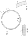
- the mirror assembly can include a light scattering region, such as a plurality of light scattering elements disposed along the length of the light pipe.
- the light scattering elements can have a pattern density that varies depending, at least in part, on the distance along the light path from the light source.
- the light scattering elements can be configured to encourage a portion of the light impacting the light scattering elements to be emitted out of the light path along a desired portion of the length of the light path.
- the amount of light scattering elements on the light path can vary depending, at least in part, on the distance along the light path from the light source.
- the pattern density can be less dense in a region generally adjacent the light source and more dense in a region spaced away from, or generally opposite from, the light source along the periphery of the mirror, thereby scattering the light to a greater degree as the intensity of the light diminishes further from the light source, and facilitating a substantially constant amount of light emitted along the length of the light pipe.
- the light scattering elements in the region generally adjacent the light source can be smaller compared to the light scattering elements in the region spaced from, or generally opposite from, or generally furthest from, the light source.
- the light source can be positioned near an upper portion of the mirror.
- the light pipe can be disposed along substantially all of the periphery of the mirror.
- the light source can emit light in a direction generally orthogonal to a standard viewing direction of the mirror.
- the light pipe can be generally circular and can include a first end and a second end. The light source can emit light into the first end, and another light source can emit light into the second end.
- the light scattering elements can be generally uniformly distributed along at least a portion of the light pipe.
- the one or more light sources can be configured to emit light in a direction generally orthogonal to a primary viewing direction of the mirror.
- the light pipe can have a length and can be disposed along substantially all of the periphery of the mirror.
- the light pipe can be configured to receive light from the one or more light sources and distribute the light generally consistently along the length, thereby providing a generally constant level of illumination to the periphery of the mirror and/or to the object reflected in the mirror.
- the one or more light sources can include a first light source configured to project light in a first direction around the periphery of the mirror and a second light source configured to project light in a second direction around the periphery of the mirror.
- the one or more light sources can be two light sources. Each of the light sources can use less than or equal to about three watts of power.
- the one or more light sources can have a color rendering index of at least about 90.
- the one or more light sources can include light emitting diodes.
- the light pipe can be configured to transmit at least about 95% of the light emitted from the one or more light sources.
- the plurality of light scattering elements can have a pattern density.
- the light scattering elements can be configured to encourage a portion of the light impacting the light scattering elements to be emitted out of the light pipe.
- the pattern density can be less dense in a region generally adjacent the light source, and the pattern density can be more dense in a region generally opposite from, spaced from, or furthest from, the light source along the periphery of the mirror, thereby facilitating a substantially constant amount of light emitted along the length of the light pipe.
- the method can include positioning the light source near an upper portion of the mirror.
- the method can include disposing the light pipe around substantially all of the periphery of the mirror. In certain embodiments, the method can include positioning the light source to emit light in a direction generally orthogonal to a main viewing direction of the mirror. In certain embodiments, the method can include positioning the light source to emit light into a first end of the light pipe and positioning another light source to emit light into a second end of the light pipe. In certain embodiments, the method can include disposing the light scattering elements in a generally uniform pattern along at least a portion of the light pipe.
- the mirror assembly can include a proximity sensor, and an electronic processor.
- the one or more light sources can be disposed at a periphery of the mirror.
- the proximity sensor can be configured to detect an object within a sensing region.
- the proximity sensor can be configured to generate a signal indicative of a distance between the object and the proximity sensor.
- the electronic processor can be configured to generate an electronic signal to the one or more light sources for emitting a level of light that varies depending on the distance between the object and the sensor.
- the proximity sensor can be positioned generally near a top region of the mirror.
- the electronic processor can be configured to generate an electronic signal to the one or more light sources to deactivate if the proximity sensor does not detect the presence and/or movement of the object for a predetermined period of time.
- the proximity sensor can be configured to have increased sensitivity after the proximity sensor detects the object (e.g., by increasing the trigger zone distance, by increasing the sensitivity to movement within a trigger zone, and/or by increasing the time period until deactivation).
- the mirror assembly can include an ambient light sensor configured to detect a level of ambient light.
- the sensing region can extend from about 0 degrees to about 45 degrees downward relative to an axis extending from the proximity sensor.
- the proximity sensor can be mounted at an angle relative to a viewing surface of the mirror.
- the mirror assembly can include a lens cover positioned near the proximity sensor. In certain embodiments, a front surface of the lens cover can be positioned at an angle relative to the proximity sensor.
- the mirror assembly can include a light pipe having a length and being disposed along substantially all of the periphery of the mirror. The light pipe can be configured to receive light from the one or more light sources and distribute the light generally consistently along the length, thereby providing a substantially constant level of illumination to the periphery of the mirror.
- the method can include configuring a proximity sensor to generate a signal indicative of a distance between an object and the proximity sensor.
- the method can include configuring an electronic processor to generate an electronic signal to the one or more light sources for emitting a level of light that varies depending on the distance between the object and the sensor.
- the method of manufacturing the mirror assembly can include positioning the proximity sensor generally near a top region of the mirror.
- the method can include configuring the electronic processor to generate an electronic signal to the one or more light sources to deactivate if the proximity sensor does not detect the object for a period of time.
- the method can include configuring the proximity sensor to have increased sensitivity after the proximity sensor detects the object.
- the method can include configuring an ambient light sensor to detect a level of ambient light.
- the method can include configuring the proximity sensor to detect an object within a sensing region extending from about 0 degrees to about 45 degrees downward relative to an axis extending from the proximity sensor.
- the method can include mounting the proximity sensor at an angle relative to a viewing surface of the mirror.
- the method can include positioning a lens cover near the proximity sensor.
- the method can include positioning a front surface of the lens cover at an angle relative to the proximity sensor.
- the method can include disposing a light pipe along substantially all of the periphery of the mirror.
- the light pipe can be configured to receive light from the one or more light sources and distribute the light generally consistently along the length, thereby providing a substantially constant level of illumination to the periphery of the mirror.
- a mirror assembly is disclosed in the context of a portable, free-standing vanity mirror, as it has particular utility in this context.
- the various aspects of the present disclosure can be used in many other contexts as well, such as wall-mounted mirrors, mirrors mounted on articles of furniture, automobile vanity mirrors (e.g., mirrors located in sun-visors), and otherwise.
- 1 inch corresponds to 2,54 cm and 1 foot corresponds to 30,48 cm.
- While some implementations described herein provide various dimensions and qualities of a single mirror, it is to be appreciated that the various dimensions and qualities can be applied to another mirror in the mirror assembly and/or to multiple mirrors of the mirror assembly (e.g., in mirror assemblies having multiple mirrors).
- different mirrors can be combined to provide a mirror assembly with a plurality of different mirror qualities in different mirrors of the assembly. For instance, in some embodiments, where multiple mirror surfaces are present in a mirror assembly, a mirror having one shape is combined with a mirror having a different shape in a mirror assembly. In some embodiments, a mirror having one tint is combined with a mirror having a different tint in a mirror assembly.
- a mirror having one power of magnification is combined with another mirror having a different magnification.
- a mirror having one size is combined with another mirror having a different size. This ability to combine different mirror features can help provide multiple options of use for a user of the mirror assembly.
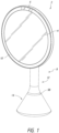
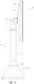
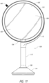
- the mirror assembly 2 includes a housing portion 8 and a visual image reflective surface, such as a mirror 4.
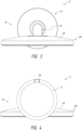
- the housing portion 8 include a support portion 20, a shaft portion 12, and/or a base portion 14.
- the housing portion 8 includes a pivot portion 16 connecting the support portion 20 and the shaft portion 12.
- the pivot portion 16 can include one or more of a ball joint (e.g., or another joint allowing multidirectional movement), one or more hinges, or otherwise.
- Certain components of the housing portion 8 can be integrally formed or separately formed and connected together to form the housing portion 8.
- the housing 8 can include plastic, stainless steel, aluminum, or other suitable materials, and/or one or more compressible materials, such as rubber, nylon, and/or plastic, on at least a portion of its outer surface.
- the mirror assembly 2 can include one or more of the components described in connection with Figures 6-8C .
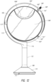
- Figure 9 illustrates another mirror assembly 102 including many components similar to the mirror assembly 2 components.
- different embodiments e.g., different mirror assemblies such as 2 and 102, etc.
- features of one embodiment correspond with features of another embodiment (e.g., are the same, substantially the same, achieve the same or similar purposes, etc.), those features are offset numerically by factors of 100 (while having the same ones and tens numerical value).
- feature 10 of mirror assembly 2 can correspond to feature 110 of mirror assembly 102.
- mirror assembly 2 of Figure 1 comprises a visual image reflective surface, such as a mirror 4
- the mirror assembly 102 of Figure 9 comprises a visual image reflective surface, such as a mirror 104.
- the mirror assembly 102 comprises a housing portion 108.
- the housing portion 108 can include one or more of a shaft portion 112, and/or a base portion 114.
- the housing portion 108 can also include a pivot portion 116 for connecting a support portion 120 to the housing 108.
- the mirror assembly 102 comprises a mirror head 103.
- the mirror head 103 of the mirror assembly 102 is connected to the pivot portion 116 and shaft portion 112 via a support portion 120 and an arm 113.
- the shaft portion 112 and/or the arm 113 can be connected to one of more portions of the mirror head 103 or the support portion 120 on a side thereof, and/or not in an interior or central region thereof, to permit the mirror head 103 or some portion thereof to rotate by a wide angle about an axis that traverses through the mirror head 103, such that respective front and rear surfaces of the mirror head 103 can be made to selectively switch positions on the mirror assembly 102.
- multiple mirrors are provided on a single mirror assembly 102 to provide multiple different optical capabilities or features, such as different magnification levels to a user.
- One or more other optical capabilities that can be provided in different mirrors in the same mirror assembly 102 are different lighting intensity, different color temperature, different tint, different mirror reflectivity, etc.
- a first mirror 104, and a second mirror 104' are provided.
- a third mirror 104" can be provided.
- more than one mirrored surface with multiple different optical capabilities or features can be provided (e.g., 2, 3, etc.) on a side (e.g., the back face 103") of the mirror head 103.
- the front face 103' of the mirror head 103 comprises the first mirror 104.
- the back face 103" comprises the second mirror 104'.
- the back face 103" comprises the third mirror 104".
- the back face of the mirror head comprises one mirror.
- more than one mirror is provided on the front face of the mirror head.
- the mirror(s) 4, 104, 104', 104" can include a generally flat or generally spherical surface, which can be convex or concave.
- the radius of curvature can depend on the desired optical power. In some embodiments, the radius of curvature can be at least about 15 inches and/or less than or equal to about 30 inches.
- the focal length can be half of the radius of curvature. For example, the focal length can be at least about 7.5 inches and/or less than or equal to about 15 inches. In some embodiments, the radius of curvature can be at least about 18 inches and/or less than or equal to about 24 inches.
- the mirror can include a radius of curvature of about 20 inches and a focal length of about 10 inches. In some embodiments, the mirror is aspherical, which can facilitate customization of the focal points.
- one or more of the mirrors of the mirror assembly 4, 104 can have a generally circular shape.
- one or more of the mirrors can have an overall shape that is generally elliptical, generally square, generally rectangular, or any other shape.
- one or more of the mirrors can have a partial shape that forms part of a standard shape such as a circle (e.g., 104"), an ellipse, square, rectangular, rhomboidal, triangular, or any other shape.
- the mirrors can be in the shape of a waxing or waning gibbous or crescent moon that, when combined, form a circle, and/or the mirrors can each be in the shape of separate corresponding or complimentary parts that, when placed together, form a substantially complete shape such as a substantially complete circle, square, rectangle, etc.
- one or more of the mirrors of the mirror assembly can have a diameter of at least about 8 inches and/or less than or equal to about 12 inches. In some embodiments, one or more of the mirrors can have a diameter of about 8 inches. In certain embodiments, one or more of the mirrors of the mirror assembly can have a diameter of at least about 12 inches and/or less than or equal to about 16 inches. In some embodiments, where multiple mirrors are present on a single mirror assembly, mirror faces having different diameters can be used in a single assembly.
- the radius of curvature of the mirror 4, 104, 104', 104" is controlled such that the magnification (optical power) of the object can be varied.
- the image of an object reflected is not magnified (e.g., has a magnification of 1X).
- the magnification is equal to or at least about 2 times larger (e.g., 2X) and/or less than or equal to about 10 times larger (e.g., 10X).
- the image of the object appears to be equal to or at least about 2 times larger (e.g., 2X) and/or less than or equal to about 10 times larger (e.g., 10X) than an unmagnified image.
- the magnification of the image of the object is equal to or at least about 5 times larger (e.g., 5X) than the object.
- the mirrors may be of different magnification or the same magnification.
- the first mirror 104 is a 5X mirror
- the second mirror 104' is a 1X mirror
- the third mirror 104" is a 10X mirror.
- the first mirror 104 is a 2X mirror
- the second mirror 104' is a 1X mirror
- the third mirror 104" is a 10X mirror.
- the first mirror 104 is a 5X mirror
- the second mirror 104' is a 2X mirror
- the third mirror 104" is a 10X mirror.
- Other arrangements, modifications, and combinations of magnification levels can be used.
- any one or more of the mirrors 104, 104', 104" can have a magnification equal to or less than about: 0.25X, 0.5X, 1X, 2X, 5X, 10X, or ranges including and/or spanning the aforementioned values.
- these different mirror magnifications can allow the user to quickly and/or to easily view portions of the face or body at different magnifications by moving the user's eyes without requiring the user to otherwise change body position or to move or reorient the mirror.
- the focal point of the mirrors on the same face can be positioned at about the same location in three-dimensional space. For example, based on the curvature and/or the shape of a mirrored surface, its focal point and degree of magnification can be adjusted and manipulated.
- two mirrors 104', 104" on one face of the mirror head 103 are shaped to have different magnification levels but are shaped and/or oriented such that the respective focal points (e.g., the points where the mirror image appears focused to the user) of each mirror are coincident, and/or are substantially or approximately coincident.
- a user when viewing the respective images of the two mirrors 104', 104" of the mirror assembly 102, a user can focus on a portion of a body part at different magnification levels by simply looking (e.g., shifting the user's eyes) from one mirror (e.g., mirror 104') to the other mirror (e.g., 104") on the same side of the mirror assembly 102, and vice versa, without requiring the user to move his or her head or body and/or without moving or otherwise adjusting the mirror.
- one mirror e.g., mirror 104'
- the other mirror e.g., 104
- the user can focus on one facial feature or body part (e.g., the eyes, eyebrows, cheeks, nose, forehead, neck, shoulder, etc.) at two magnification levels by simply moving the eyes from one mirror to the other without appreciably moving any other body part (e.g., not appreciably moving the head, or neck, etc.) to bring the reflected image into focus.
- the respective focal points of the mirrors are identical, substantially identical, or at least located near each other, so the viewer can view one body part at a plurality of different magnification levels by moving the eyes.
- the distance between the respective foci of a plurality of mirrors on the same side of a face of the mirror assembly 102 can be less than or equal to about the average focal length of the human eye in the target population for which the mirror is made.
- the respective focal points of the mirrors are generally coincident and/or generally collinear and/or generally within the same focal depth.
- a 1X mirror has a focal length that is infinite.
- the image created by the 1X mirror will be in focus everywhere and therefore not blurry at the location where a user has positioned her face to view an image created by another mirror having a different level of magnification at a particular focal point.
- the user can focus on a body part (e.g., a facial feature) in, for instance, a magnifying mirror and in the 1X mirror on the same side of the mirror assembly at about the same distance from the mirror, without having to move the body part when the user shifts her gaze from one mirror to the other mirror.
- a body part e.g., a facial feature
- the user can focus on a face or body part at two magnifications substantially simultaneously.
- the user can contract (e.g., shrink, reduce, etc.) the image size of the facial feature and/or body part reflected in the mirror by simply shifting eyes from one mirror to the other (e.g., from 1X to 10X, etc.). Because the user need only shift her eyes from one mirror to the other to magnify or contract a body part, the user is able to apply make-up quicker and easier, for example, without having to reposition the body or the mirror to achieve higher or lower magnification of the same facial feature.
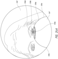
- a user's reflected eye is viewed at a transition area from one mirror 104' to the next 104" across a seam 104a (e.g., the interface) between the mirrors 104', 104".
- the mirrors 104', 104" of one mirror face 103" can be positioned (e.g., angled, oriented, recessed, and/or aligned) such that there is substantially no break, interruption, and/or delay in or along at least one pathway traversed by a point in the reflected image 104d, 104e of a moving object as it passes from one mirror to the next (e.g., from mirror 104' to the mirror 104", or vice versa).
- the mirrors 104', 104" can be positioned (e.g., angled, oriented, recessed, and/or aligned) such that there is substantially no detectable jump in or along at least one pathway traversed by a point in the reflected image 104d, 104e of a moving object as it passes from one mirror to the next.
- this smooth transition can occur even when the mirrors 104', 104" have different magnification levels.
- the smaller mirror 104" is of higher magnification power than the larger mirror 104'.
- this substantially unbroken pathway of a point or image (e.g., intact image, uninterrupted image, etc.) and/or the smooth transition occurs at a particular area 104b (an uninterrupted transition point and/or position) along the transition 104a between a first mirror 104' and a second mirror 104".
- the mirrors are positioned so that a substantially unbroken image and/or smooth transition occurs at multiple and/or all the positions along the interface of a first mirror and a second mirror.
- the uninterrupted transition position of the mirrors 104', 104" is at an area near or substantially at the center or mid-point of the interface 104b between the mirrors 104', 104".
- the transition of the reflected image becomes less smooth (e.g., more broken) as the reflected image is viewed at positions farther away from the smooth transition area 104b (e.g., at points near the start of the interface 104c of the mirrors 104', 104"). As discussed elsewhere herein, this broken image may occur because the surfaces of the mirrors 104', 104" are not in parallel planes at positions farther from the smooth transition area 104b. In some embodiments, away from the smooth transition area 104b, a break in an image results and at least a portion of a reflected object disappears at the seam between the mirrors (and/or the reflection jumps from one mirror to the other).
- the mirrors are positioned so that a smooth transition is achieved anywhere along the interface between the mirrors (e.g., at or near the periphery of the seam, at or near the start of the seam, at or near the end of the seam, at or near the midpoint of the seam, etc.).
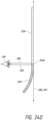
- Figure 24B is provided for illustration of certain properties of a concave mirror 190 (e.g., a mirror that substantially conforms to a portion of a sphere, a mirror that substantially conforms to a portion of a paraboloid, an aspherical mirror, etc.).
- a concave mirror 190 has a principal axis 191 normal to the center of the concave mirror 190 and passing through its focal point 192.
- Incident light traveling normal to the mirror 190 along the principal axis of the mirror 190 travels through the focal point 192 and reflects directly backward along the principal axis 191 and back through the focal point 192.
- Incident light traveling toward the concave mirror along the principal or optical axis 191 is also reflected directly backward along the path of the incoming incident light ray (not shown).
- an incident ray 190b' traveling parallel to the principal axis 191 on the way to the mirror is reflected at an angle as a ray 190b" that travels back through the focal point.
- An incident ray 190a' that passes through the focal point 192 on the way to the mirror 190 is reflected as a ray 190a" that travels parallel to the principal axis 191.
- the uninterrupted transition occurs as a result of the sight lines 182 and 183 on edges of the mirrors 104', 104" adjacent to the seam being generally or substantially parallel with or substantially or generally collinear with the principal or optical axis of the mirror 104". In some embodiments, the uninterrupted transition occurs as a result of at least a portion of the surface of the planar mirror 104' being in an approximately or substantially parallel plane with respect to a tangential plane 181 of the curved mirror 104" (as shown in Figure 24C ) when viewed at a normal viewing angle in front of the mirror face 103" and across the seam 104a.
- the uninterrupted transition occurs as a result of at least a portion of the surface of a planar mirror 104' being in approximately or substantially the same plane as a tangential plane of the curved mirror 104" (as shown in Figure 24D ) when viewed at a normal viewing angle in front of the mirror face 103" and across the seam 104a.
- Figures 24C and 24D show side views of tangential planes 181, 281 of concave mirrors 104", 204".
- a concave mirror 104" has a tangential plane 181 that is approximately parallel to the plane 180 of a planar mirror 104"
- a smooth transition can be achieved when an object is moved across the seam and viewed along different sight lines 182, 183 traversing the seam 104a of the mirrors 104', 104".
- This effect can also be achieved where a concave mirror 204" has a tangential plane 281 that is approximately or substantially in the same plane 280.
- the radius of curvature of the convex mirror 104" falls on the sight light 183 at which the smooth transition occurs.
- the sight light 183 is perpendicular to the tangential plane 181 of the concave mirror 104".
- any suitable combination of different orientations and/or angles between the planar mirror and the curved mirror can be used to eliminate image jump between mirrors.
- a tipping or canting or convergence of a line normal to the reflective surface of one mirror toward a line normal to the reflective surface of another mirror can avoid or resist image jump.
- Other optical properties of the mirrors can be responsible for the smooth transition instead of or in addition to a parallel orientation between the sight lines 182 and 183 and the principal or optical axis of the plane of a planar mirror and the tangential plane of a curved mirror, or the angle formed by the lines normal to the reflective surfaces of the respective mirrors.
- a step 104f exists between the two mirrors 104', 104" at the smooth transition area 104b.
- this step can be essentially "invisible" (e.g., positioned behind the mirrored surface 104') when the mirror face 103' is viewed at a normal viewing angle.
- a very small or essentially no distracting visible interruption occurs between the mirrors 104', 104" when viewed at a normal viewing angle.
- this step becomes smaller and smaller toward the periphery of the mirror head.
- the mirrors 104', 104" are substantially or approximately flush 195.
- one of the mirrors 104' is planar and the other mirror 104" is not. In some embodiments, one of the mirrors 104' is planar and the other mirror 104" is magnifying (e.g., concave). In some embodiments, one mirror 104" is recessed within and/or inset within the other mirror 104'. In some embodiments, where one mirror 104" is recessed and/or inset within the other mirror 104', at least a portion of the perimeter of the inset mirror 104" is even with and/or is not inset from the other mirror 104'. In some embodiments, the mirrors share at least portion of their perimeters and/or other boundaries.
- the combined outer perimeters of the mirrors form a complete or substantially complete shape (e.g., a circle, square, rectangle, etc.).
- each mirror 104', 104" forms a portion of a perimeter of a complete or substantially complete shape (e.g., a circle, square, rectangle, etc.).
- the mirrors 104', 104" are permanently attached to the mirror head 103 such that the mirrors 104', 104" cannot be removed by a user without tools or risk of damage (e.g., are not magnetically attached).
- the mirrors 104', 104" are oriented on the mirror face 103" to share at least a focal point within the viewing area of the mirror assembly 102.
- the mirrors 104', 104" are differently shaped (e.g., have different circumferences shapes and/or sizes and/or have differently shaped and/or sized perimeters).
- an imaginary plane formed atop one of the mirrors 104" and resting on at least three of the topmost points of the mirror 104" is not parallel to or coplanar with an imaginary plane formed atop of the other mirror 104' and resting on at least three topmost points of the other mirror 104'.
- these imaginary planes converge towards one another when traveling in one direction and diverge from each other when traveling a different direction.
- One or more of the arm 113, the support portion 120, and the mirror head 103 are rotatable or twistable to provide multiple mirror angles with respect to the base portion 114 of the mirror assembly 102.
- the user is able to reposition the mirror image based on the user's height, body position (e.g., sitting or standing), etc.
- the support portion 120 of the mirror assembly 102 is attached to the arm 113 via a hinge 113'.
- the hinge 113' allows axial movement of the support portion 120 and, consequently, the mirror head 103 about the axis of the hinge 113'.
- the hinge 113' can include one or more of a ball joint, one or more hinges, or otherwise.
- hinge 113' allows the mirror head to be pivoted in one or more directions (e.g., up, down, right, left, clockwise, counterclockwise, etc.).
- the hinge 113' can comprise a vertical swivel joint (allowing up and down movement).
- the hinge 113' allows the mirror to be viewed at different upward or downward viewing angles.
- the front mirror face 103' and support member 120 can be moved from a substantially vertical to a substantially horizontal position (so that the mirror face 103' is directed upwardly, forwardly, or downwardly).
- the hinge 113' enables positioning of the support portion 120 (and, consequently, the mirror face(s)) at various different angles, where an angle of approximately 0° indicates that the support structure 120 is substantially vertical and where 90° indicates that the support structure is substantially horizontal (and directed upwardly).
- the hinge 113' enables positioning of the support portion 120 at angles of equal to about 0°, equal to or less than about 45°, equal to or less than about 90°, or ranges including and/or spanning the aforementioned values.
- a hinge 113' on the arm 113 and the support portion 120 is static relative to the arm and/or can be locked in place and held in a static position (e.g., by using a locking joint).
- the support portion 120 does not rotate with respect to the arm 113, the support portion is fixed at an angle equal to about 0°, less than or equal to about 15°, less than or equal to about 40°, or ranges including and/or spanning the aforementioned values.
- the pivot portion 116 enables positioning of the mirror head 103 and support portion 120 at different side-to-side angles relative to a central position including angles equal to or at least: about 10°, about 20°, about 45°, or ranges spanning the aforementioned values.
- the pivot portion 116 comprises a lateral swivel joint (allowing right to left movement).
- the pivot portion 116 does not move and/or can be locked in a neutral and/or central position.
- the hinge 113' and the pivot portion 116 both move, the user can position the mirror face at several angles in any one of the aforementioned up-and-down and side-to-side angles simultaneously. This movability increases the ease with which the mirror 104, 104', 104" can be directed to provide easy viewing of a desired body part (e.g., a facial feature).
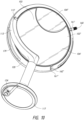
- the mirror head 103 and support portion 120 are attached to each other via a hinge assembly 111 (a hinge, swivel, ball-joint, etc.) shown in Figures 16-18 from the front face of the mirror assembly 103' with the mirror 104 removed.
- the mirror head 103 can be rotated about the axis of the hinge assembly 111 within the support portion 120.
- this rotation allows the user to transition from the front face 103' (e.g., mirror 104) to the back face 103" (e.g., mirrors 104', 104") by flipping (e.g., rotating on an axis, etc.) the mirror head 103 within the support portion 120 (e.g., moving the mirror head 103 backward or forward) without movement of the support portion 120.
- the mirror head 103 moves axially about an axis created by the hinge assembly 111 while the support portion 120 remains in place and/or static (e.g., without movement via the hinge 113' or the pivot portion 116).
- the mirror head 103 can be moved within the support portion 120 from a start position (e.g., an angle ⁇ of about 0°, shown in Figure 19 ) to an end position (e.g., an angle ⁇ of about 180°). The mirror head 103 can then be rotated back by moving it from the end position (e.g., an angle ⁇ of about 180°) back to the starting position (e.g., an angle ⁇ of about 0°).
- a start position e.g., an angle ⁇ of about 0°, shown in Figure 19
- an end position e.g., an angle ⁇ of about 180°
- the mirror head 103 can then be rotated back by moving it from the end position (e.g., an angle ⁇ of about 180°) back to the starting position (e.g., an angle ⁇ of about 0°).
- the mirror assembly comprises a handle 160 (e.g., a knob, lever, pop-pin, etc.).
- the handle 160 is affixed to, connected to, unitary with, or otherwise attached to the mirror head 103.
- the handle 160 facilitates movement from the front mirror face 103' to the back mirror face 103" (or vice versa), by simply rotating, flipping, turning the mirror head 103 via the handle 160 about an axis of within the support portion 120 of the mirror head 103 (as shown in Figures 16-18 ) as described above.
- the handle 160 can be used to rotate the mirror head 103 about the hinge assembly 111 axis while the support portion 120 remains in place (e.g., static), without requiring the user to touch any mirror face or side, thus avoiding smudges or finger prints on the mirror face.
- the user can rotate the mirror head 103 within the support portion 120 to view the back face 103" mirrors 104', 104". This movement can be accomplished, for example, when the user pushes or presses the handle 160 away from her through an arc of motion.
- the user moves the handle 160 in the backward direction along an arc (from an angle ⁇ of about 0°) to achieve an angle ⁇ of about 90° and, after passing an angle ⁇ of about 90°, pulls the handle 160 downwardly and towards the support portion 120 to achieve an angle ⁇ of about 180°.
- the front face 103' of the mirror assembly can again be viewed by pushing the handle 160 back and upward to rotate the mirror head 103 from the second position (e.g., an angle ⁇ of about 180°) to achieve an angle ⁇ of about 90°.
- the user can pull the handle 160 upwardly along an arc and toward the user to achieve an angle ⁇ of about 0°.
- the mirror assembly can comprise an actuator in the form of a button, switch, sensor, or capacitive touch sensor module that, upon actuation (e.g., by pressing a button, swiping a finger across a portion of a sensor, pressing a sensor, etc.) moves the mirror head from an angle ⁇ of about 0° to about 180° or vice versa.
- an actuator in the form of a button, switch, sensor, or capacitive touch sensor module that, upon actuation (e.g., by pressing a button, swiping a finger across a portion of a sensor, pressing a sensor, etc.) moves the mirror head from an angle ⁇ of about 0° to about 180° or vice versa.
- the hinge assembly 111 is spring-loaded.
- the spring (not shown), or another similar feature that causes directional resistance (e.g., a magnet, a friction pad, a cam, etc.), can imbue the mirror head 103 with a weighted feel.
- a weighted feel For example, in some embodiments, when moving the mirror head 103 from its start position (from an angle ⁇ of 0°, shown in Figures 19 and 20 ), an initial resistance is felt by the user and then less resistance as movement continues until the mirror head 103 reaches its end position (an angle ⁇ of 180°) or some intermediate position.
- the mirror head 103 when moving the mirror head 103 from its end position (an angle ⁇ of 180°), an initial resistance is felt by the user and then less resistance as movement continues until the mirror head 103 reaches the start position (angle ⁇ of 0°, shown in Figures 19 and 20 ), or some other position.
- the user can let go of the handle 160 and the hinge assembly 111 allows a generated momentum to carry the mirror head 103 to the end position (an angle ⁇ of 180°).
- the user can let go of the handle 160 and the hinge assembly 111 allows generated momentum to carry the mirror head 103 back into the start position.
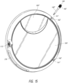
- the handle 160 is configured to move from a first retaining portion, such as a bay 161' (e.g., groove, aperture, slot, etc.), in the support portion 120 to a second bay 161" (e.g., groove, aperture, slot, etc.) in the support portion 120 (as shown in, for example, Figure 15 ).
- a first retaining portion such as a bay 161' (e.g., groove, aperture, slot, etc.)
- a second bay 161" e.g., groove, aperture, slot, etc.
- the first bay 161' is an upper slot on the support portion 120 located above the second bay 161".
- the second bay is a lower slot on the support structure 120, located below the first bay 161' (as shown in Figure 12 ).
- the bays 161', 161" of the support portion 120 engage the handle 160 (e.g., frictionally, magnetically, or otherwise) to hold the handle 160 in the bay 161', 161" until the user applies enough force to move the mirror head 103 out of the bay 161', 161" (e.g., via the handle 160).
- the bays 161', 161" comprise magnets 162', 162" to engage, attract and/or hold the handle 160.
- the handle 160 comprises frictional elements (e.g., knurlings, roughenings, ribs, rubber) and/or the bay has frictional elements (e.g., knurlings, roughenings, ribs, rubber) to hold the stem in the bay.
- the handle 160 comprises a magnet (or is magnetic) and the bay 161', 161" comprises an oppositely polarized magnet (or a magnetic insert attracted by the handle).
- the bay is sized slightly smaller than a stem so that the walls of the bay engage the stem as the handle is moved into position in the bay.
- the bay has an entrance (e.g., mouth) that comprises one or more resilient materials but slightly deformable materials (e.g., plastic, rubber, Teflon, etc.) so that a small amount of force must be applied to the handle to move the handle past the entrance of the bay and into the bay.
- the bay beyond the mouth of the bay, the bay comprises an opening section where the walls of the bay do not contact the stem or handle.
- the handle is held in the opening section of the bay until moved past the mouth of the bay again.
- the handle 160 comprises a securing member (e.g., pop-pin, etc.) that engages the support portion 120 of the mirror assembly 102 (e.g., in a bay or via a hole in the support portion 120) via a catch-mechanism 173 (as shown in, for example, Figures 16-18 ).
- the securing member recoils through an aperture in the support portion 120 of the catch-mechanism 173.
- the handle 160 snaps into place in the start position ( ⁇ of about 0°) or end position ( ⁇ of about 180°).
- the securing member comprises a spring-loaded pop-pin.
- the securing member may be physically mounted (e.g. welded or screwed into place) or unitary with a portion of the mirror head 103.
- the handle 160 by pulling the pop-pin out and away from the support portion 120, the handle 160 releases and the mirror head 103 freely moves with respect to the support portion 120.
- the handle 160 can be released after the pin portion of the pop-pin exits the aperture (e.g., an aperture in a bay) and the pin will automatically pop and/or snap back into place when it reaches the start ( ⁇ of about 0°) or end position ( ⁇ of about 180°).
- the pop-pin can be pulled out to allow movement of the mirror head from one position to the next even after the pop-pin has been let go.
- the pop-pin can be released from a bay by actuating it, such as by depressing it (e.g., pushing the handle into or toward the mirror assembly).
- the pop-pin design can be used with or without other design features pertaining to the movement of the mirror head described elsewhere herein.
- the mirror head 103 has a pop-pin, but also one or more elements that imbue it with a weighted feel during movement and/or features that provide an initial resistance and then less resistance as movement continues until the mirror head reaches its next position.
- the handle can alternatively or additionally be provided with one or more internal electronic components (e.g., one or more switches or dials) in electronic communication with a controller that are configured to actuate or adjust one or more electronic parameters or features of the mirror assembly.
- the handle interacts with a controller configured to actuate or adjust the intensity, brightness, color, and/or temperature of the light emitted by the mirror.
- the handle is in electronic communication with a controller configured to actuate or adjust any other adjustable light variable disclosed herein.
- the handle can be actuated to turn the power to the mirror assembly on or off.
- actuation of the handle activates a display (e.g., a virtual display, LCD, OLED, LED, or the like) as described elsewhere herein.
- the handle can be used to select settings from the display.
- the handle can be used to select downloaded light settings as described elsewhere herein.
- the handle is actuated in one or more ways (e.g., by twisting, pushing, and/or pulling the handle, etc.).
- a plurality of handles (2, 3, 4, or more) is provided.
- a first handle can be provided to change the orientation of the mirror head and a second handle can be provided to actuate or adjust one or more of the electronic parameters or features of the mirror.
- the support portion 120 does not comprise a bay. In some embodiments, instead of a bay, a different retaining portion, such as a pad or flat surface, is used to retain or sequester the mirror head 103 in place.
- the pad may be a material or other feature (e.g., a dimple, a nub, etc.) that is magnetic or adhesive and that attracts or sticks to the handle (not shown). In some embodiments, the pad can be substantially flat. In some embodiments, as discussed above, an aperture in the support portion 120 can be used to fix the mirror head 103 in place (e.g., with a pop-pin).
- the handle 160 advantageously allows the user to avoid making direct physical contact with the mirror 104, 104', 104".
- the user can avoid making fingerprints or smudges on any of the mirror surfaces as the mirror is transitioned between one face 103' to the next 103".
- a user can transition from one mirror face to the next without needing to wash one of the mirror surfaces.
- avoiding smudges leads to less wear on the mirror over time because the mirror surface need not be washed (e.g., with cloth or tissue that can abrade the mirror surface). Washing of the mirror surface can eventually lead to dulling of the surface and loss of image brilliance.
- the risk that electronic components of the mirror assembly 102 are damaged by water, cleaning solution, etc. is lowered or minimized.
- the handle 160 comprises a stem 160".
- Figure 15 shows the handle removed from the head 103 of the mirror (shown) with the arm 113, shaft portion 112, and base 114 removed.
- the handle 160 comprises a grip 160'.
- the stem 160" has a diameter that is smaller than or equal to the diameter of the grip 160'.
- the diameter of the grip is about 2 times larger than (e.g., about twice as large as) the diameter of the stem.
- the grip 160' has frictional elements (e.g., knurlings, roughenings, ribs, rubber, etc.) that allow it to be easily grasped by the user to facilitate movement of the mirror head 103.
- frictional elements e.g., knurlings, roughenings, ribs, rubber, etc.
- the handle 160 can be located at various positions about the mirror head 103.
- a "12 o'clock" position of the mirror can be viewed as the 0°/360° position (e.g., the 0°/360° mark of a 360° protractor).
- these degree marks can be denoted as values of "° ⁇ ".
- the "3 o'clock" position coincides to a 90° ⁇ mark
- the 6 o'clock position coincides to a 180° ⁇ mark
- the 9 o'clock position coincides to a 270° ⁇ mark, etc.
- the top bay 161' is positioned between about 340° ⁇ and about 290° ⁇
- the bottom bay 161" is positioned between about 200° ⁇ and about 250° ⁇ .
- the top bay 161' is positioned at about 315° ⁇ and the bottom bay 161" is positioned at about 225° ⁇ .
- the bays and the handle are located on the other side of the mirror head 103.
- the top bay is positioned between about between about 20° ⁇ and about 70° ⁇ and the bottom bay is positioned between about 110° ⁇ and about 160° ⁇ .
- the top bay is positioned at or about at 45° ⁇ and the bottom bay is positioned at or about at 135° ⁇ .
- the arm may also be on either side of the mirror.
- one or more mirrors 104, 104', 104" of the mirror assembly 102 can have a thickness of at least about 2 mm and/or less than or equal to about 3 mm. In some embodiments, the thickness is less than or equal to about two millimeters and/or greater than or equal to about three millimeters, depending on the desired properties of the mirror (e.g., reduced weight or greater strength).
- the surface area of a mirror 104 of the mirror assembly can be substantially greater than the surface area of the base 114. In other embodiments, the surface area of the image-reflecting surface of the mirror is greater than or equal to the surface area of the base.
- one or more of the mirrors can be highly reflective (e.g., can have at least about 90% reflectivity). For instance, in some embodiments, one or more of the mirrors have greater than about 70% reflectivity and/or less than or equal to about 90% reflectivity. In other embodiments, one or more mirrors have at least about 80% reflectivity and/or less than or equal to about 100% reflectivity. In certain embodiments, one or more mirrors have about 87% reflectivity. In some embodiments, one or more of the mirrors can be cut out or ground off from a larger mirror blank so that mirror edge distortions are diminished or eliminated. In some embodiments, one or more filters can be provided on the one or more of the mirrors to adjust one or more parameters of the reflected light.
- the filter comprises a film and/or a coating that absorbs or enhances the reflection of certain bandwidths of electromagnetic energy.
- one or more color adjusting filters such as a Makrolon filter, can be applied to the one or more mirrors to attenuate desired wavelengths of light in the visible spectrum.
- one or more of the mirrors can be highly transmissive (e.g., nearly 100% transmission). In some embodiments, transmission can be at least about 90%. In some embodiments, transmission can be at least about 95%. In some embodiments, transmission can be at least about 99%.
- the one or more mirrors can be optical grade and/or comprise glass. For example, one or more of the mirrors can include ultraclear glass. Alternatively, the one or more of the mirrors can include other translucent materials, such as plastic, nylon, acrylic, or other suitable materials. In some embodiments, one or more of the mirrors can also include a backing including aluminum or silver. In some embodiments, the backing can impart a slightly colored tone, such as a slightly bluish tone to the mirror. In some embodiments, an aluminum backing can prevent rust formation and provide an even color tone.
- the one or more mirrors can be manufactured using molding, machining, grinding, polishing, or other techniques.
- the mirror assembly 2, 102 includes one or more light sources configured to transmit light.
- the mirror assembly 2, 102 can include a plurality (e.g., 2, 3, 4, 5, 6, 7, 8, or more) of light sources 30a, 30b, 130a', 130a", 130b', 130b".
- Various light sources can be used and can be housed behind the cover member 6, 106.
- the light sources can include light emitting diodes (LEDs).
- LEDs light emitting diodes
- other light emitters can be used (e.g., fluorescent light sources, incandescent light sources, halogen light sources, etc.).
- LEDs may offer advantages over other light emitters, including longer lifetimes and higher color rendering indices.
- each light source can comprise a plurality (e.g., one, two, three, four, five, or more) of LEDs (or other light emitters).
- the left light source 130b', 130b" can comprise two, as shown in Figure 16 (or four LEDs) and the right light source can comprise two (130a', 130a") or four LEDs.
- one or more LEDs within a single light source can be the same or different (e.g., have the same or a different color or color temperature).
- a light source comprising four LEDs can comprise two pairs of two LEDs where each LED in a pair is identical (e.g., a pair of two red LEDs and a pair of two blue LEDs).
- each LED in a single light source is different.
- the light sources can comprise LEDs that are the same (e.g., having the same color, temperature, and number of LEDs in an each light source) or different (e.g., having one or more LED that is different from an LED of different light source).
- different light sources of the mirror assembly are independently adjustable to provide accomplish any lighting environment desired.
- LEDs can be paired with other LEDs of lower or higher color temperatures.
- LEDs can be paired with other LEDs of with colors that have lower or higher wavelengths.
- the light sources can be positioned in various orientations in relation to each other, such as side-by-side, back-to-back, or otherwise.
- the light sources can be positioned to emit light in opposing directions (as shown in Figures 6 and 16 ).
- a first light source 30a projects light in a first direction (e.g., clockwise) around the periphery of the mirror 4
- a second light source 30b projects light in a second direction (e.g., counter-clockwise) around the periphery of the mirror 4.
- the light source 30a can project light toward a channel 48 that holds the light pipe 10 (not shown) of the mirror assembly 2.
- multiple light sources can be positioned to direct light into a channel 148 that houses the light pipe.
- a first light source 130a', 130a" projects light in a first direction (e.g., counter-clockwise) around the periphery of the mirror 104 (not shown)
- a second light source 130b', 130b" projects light in a second direction (e.g., clockwise) around the periphery of the mirror 104.
- the light sources can be positioned to emit light generally and/or substantially orthogonally to the viewing surface of the mirror assembly 2, 102.
- the light sources can be positioned to emit light tangentially in relation to the periphery of the mirror 4, 104, 104', 104".
- the light sources are configured to provide multiple colors of light and/or to provide varying colors of light.
- the light sources can provide two or more discernable colors of light, such as red light and yellow light, or provide an array of colors (e.g., red, green, blue, violet, orange, yellow, and otherwise).
- the light sources are configured to change the color or presence of the light when a condition is met or is about to be met. For example, certain embodiments momentarily change the color of the emitted light to advise the user that the light is about to be deactivated.
- either or both the color and the color temperature of the light emitted from the mirror assembly 2, 102 is independently adjustable.
- the light emitted from the light sources can be configured to mimic or closely approximate light encountered in one or a plurality of different natural or non-natural light environments.
- the light emitted from the mirror can mimic natural light (e.g., ambient light from the sun, moon, lightning, etc.).
- lighting conditions that match (or closely approximate) restaurants e.g., incandescent lights, candlelight, etc.
- offices e.g., fluorescent lights, incandescent lights, and combinations thereof
- outdoor venues at different times of day dawn, morning, noon, afternoon, sunset, dusk, etc.
- outdoor venues at different seasons spring, summer, fall, winter
- outdoor venues having different weather conditions unsunny, overcast, partly cloudy, cloudy, moonlit, starlit, etc.
- sporting arenas, opera houses, dance venues, clubs, auditoriums, bars, museums, theatres, and the like can be achieved using the mirror assembly.
- the light emitted from the mirror comprises a substantially full spectrum of light in the visible range.
- the mirror assembly can be configured to permit a user to select among the different types of light (e.g., color, temperature, intensity, etc.) emitted from the one or more light sources, either on the mirror assembly or from a remote source, or the mirror assembly can be configured to automatically select among the different types of light emitted from the one or more light sources.
- different types of light e.g., color, temperature, intensity, etc.
- the intensity of individual light sources is independently adjustable.
- changes in color temperatures can be achieved by pairing and/or mixing one or more LEDs having one color temperature with one or more other LEDs having different color temperatures. The relative intensity of light from those LEDs can then be individually adjusted (e.g., by adjusting the brightness of one or more LEDs) to increase or decrease the color temperature.
- changes in colors e.g., hues, shades, tints, tones, tinges, etc.
- the intensity of light emitted from different colored LEDs can be individually adjusted to cause a color change (e.g., to a color an individual LED or to colors achieved through combinations of the light emitted from the LEDs - color mixing). Adjusting the relative intensity of different LEDs can allow the user to adjust the color of the light emitted by the light sources, the color temperature of the light emitted by the light sources, the brightness of the light emitted by the light sources, or combinations thereof. In some embodiments, the intensity of individual LEDs can be adjusted automatically (by selecting a preset light configuration, a downloaded light configuration, or an uploaded configuration) or manually (e.g., by adjusting color, tint, brightness, intensity, temperature, or others with manual user adjustments). In some embodiments, these adjustments allow a user to select the light conditions that mimic any light environment.
- the light sources have a color temperature of greater than or equal to about 4500 K and/or less than or equal to about 6500 K. In some embodiments, the color temperature of the light sources is at least about 5500 K and/or less than or equal to about 6000 K. In certain embodiments, the color temperature of the light sources is about 5700 K. As an example and as discussed elsewhere herein, in some embodiments, light emitters can be paired with other light emitters to give desired colors and color temperatures.
- LEDs e.g., 1, 2, 3, 4 or more having one color temperature (e.g., of 2700K) can be paired and/or mixed with LEDs (e.g., 1, 2, 3, 4 or more) having a different color temperature (e.g., of 6500K) to form a single light source.
- one or more LEDs e.g., 1, 2, 3, 4 or more
- having a first color e.g., red, orange, yellow, green, blue, indigo, violet, and the like
- one or more LEDs e.g., 1, 2, 3, 4 or more having a different color.
- a light source can be formed using LEDs (e.g., one or more LEDs) that emit incandescent light color temperatures and LEDs (e.g., one or more LEDs) that emit sunlight color temperatures.
- LEDs e.g., one or more LEDs
- LEDs e.g., one or more LEDs
- LEDs having color temperatures in the range from about 1700 K to about 2500 K, from about 2500K to about 3500 K, from about 3500 K to about 4500 K, from about 4500K to about 5500 K, from about 5500 K to about 6500K or from about 6500K to about 7000K can be independently paired with LEDs having colors temperatures within these same or different ranges.
- the light sources can be adjusted to have a color temperature in the range from about 1700 K to about 6500 K from about 4500K to about 6500 K. In some embodiments, the light sources have a color temperature of greater than or equal to about 2400 K and/or less than or equal to about 6800 K. In some embodiments, the color temperature of the light sources is at least about 5500 K and/or less than or equal to about 3000 K. In certain embodiments, the color temperature of the light sources is about 2700 K or about 6500K.
- Color temperatures and intensities can be selected by a user to duplicate or replicate particular light environments to improve the selection of make-up color palates, to apply make-up in optimal configurations and patterns, and to optimize grooming and make-up application outcomes. For instance, a person applying make-up to be worn at a candlelit restaurant may wish to match the color temperature and light intensity of that environment when applying make-up. A person who is applying make-up to be worn at a sunlit picnic may wish to match the color temperature and light intensity of that environment when applying make-up. Thus, a user can select particular temperatures of light to replicate lighting conditions.
- differing light emitters e.g., LEDs
- the light emitters are controlled by an algorithm that selects individual light emitter intensities to provide an array of intensities, color temperatures, and color palates.
- the light sources have a color rendering index of at least about 70 and/or less than or equal to about 90.
- Certain embodiments of the one or more light sources have a color rendering index (CRI) of at least about 80 and/or less than or equal to about 100.
- the color rendering index is high, at least about 87 and/or less than or equal to about 92.
- the color rendering index is at least about 90.
- the color rendering index can be about 85.
- the light sources have a color rendering index of at least about 45 and/or less than or equal to about 95.
- Certain embodiments of the one or more light emitters 64 have a color rendering index of at least about 50 and/or less than or equal to about 100.
- the light emitters have a color rendering index of at least about 87 and/or less than or equal to about 92. In some embodiments, the light emitters have a color rendering index of at least about 80 and/or less than or equal to about 85. In some embodiments, the light emitters have a color rendering index of at least about 70 and/or less than or equal to about 75. In some embodiments, the light emitters have a color rendering index of at least about 45 and/or less than or equal to about 55.
- the luminous flux can be in a range from about 1 lm to about 110 lm. In some embodiments, the luminous flux can be adjusted to be less than or equal to about 1 lm, about 10 lm, about 20 lm, about 30 lm, about 40 lm, about 50 lm, about 60 lm, about 70 lm, about 80 lm, about 90 lm, about 100 lm, about 110 lm, about 140 lm, about 160 lm, about 170 lm, about 180 lm, values between the aforementioned values, ranges spanning the aforementioned values, or otherwise.
- the luminous flux can be at least about 80 lm and/or less than or equal to about 110 lm. In some embodiments, the luminous flux can be at least about 90 lm and/or less than or equal to about 100 lm. In some embodiments, the luminous flux can be about 95 lm.
- each light source consumes at least about 2 watts of power and/or less than or equal to about 3 watts of power. In certain embodiments, each light source consumes about 2 watts of power.
- the forward voltage of each light source can be at least about 2.4 V and/or less than or equal to about 8.0 V. In some embodiments, the forward voltage can be at least about 2.8 V and/or less than or equal to about 3.2 V. In some embodiments, the forward voltage is about 3.0 V. In some embodiments, the forward voltage can be at least about 5.5 V and/or less than or equal to about 7.5 V. In some embodiments, the forward voltage is about 2.5 to about 3.5 V.
- the width of each the light pipe 10, 110 (measured generally radially from the center of the mirror 4, 104) can be less than or equal to about 30 mm, about 20 mm, about 10 mm, about 7.5 mm, about 6.5 mm, about 5.0 mm, about 4.0 mm, values between the aforementioned values, or otherwise.
- the mirror assembly 2 can include a sensor assembly.
- the sensor assembly can be positioned near a lower region of the mirror assembly 2 behind the cover member 6.
- the sensor assembly can be positioned near an upper region of the mirror assembly 102 behind the cover member 106 or elsewhere (e.g., the bottom, a side, or otherwise).
- the sensor assembly can be disposed along any other portion of the mirror assembly 2, 102 or not positioned on the mirror assembly 2, 102.
- the sensor assembly can be positioned in any location in a room in which the mirror assembly 2, 102 sits.
- the sensor assembly can be located in a phone or other handheld device that activates the mirror assembly 2 when the user is in proximity to it.
- the sensor assembly 28, 128 can include one or more transmitters 36a, 36b, 136 and receivers 38, 138 as shown in Figures 6 and 16 .
- the sensor assembly 28, 128 comprises a housing 28' that supports the one or more light transmitters and one or more receivers, each of which can be provided behind the cover member 6, 106.
- the housing comprises hard or rigid plastic (e.g., injection molded or otherwise), rubber, synthetic polymer, metal, composite, or another similar material.
- the housing comprises a projection (e.g., a step, lip, elevated platform, etc.; not shown) that projects from the main body of the sensor assembly 28, 128.
- the sensor assembly 80 further comprises a gasket.
- the sensor assembly further comprises a coverslip (not shown).
- the coverslip fits over and/or holds the gasket in contact with or within the housing and the gasket is held in place by the housing via the projection.
- the coverslip fastens into the housing using a fastener (e.g., a snap, clip, screw, etc.).
- the coverslip provides consistent distributed pressure against the gasket partially compressing it and/or holding it flush against the housing via the projection.
- the coverslip, the gasket, housing assembly reproducibly provides a separation of a signal from the transmitter 36a, 36b, 136 signal from the receiver 38, 138 signal.
- housing of the sensory assembly 28, 128 beneficially lessens and/or minimizes bleeding of signal from the transmitters 36a, 36b, 136 to the receiver 38, 138 (e.g., laterally escaping or otherwise diffusing from the transmitters to the receiver through a portion of the sensor assembly). In some embodiments, this configuration can facilitate replacement and fixation of the sensor assembly in the mirror assembly 2, 102.
- the gasket is composed of a soft, resilient, and/or flexible material, such as a material selected from one or more of the following: silicone, PTFE, rubber, polyethylene, nylon, polypropylene, composite, and the like.
- the sensor assembly can include a proximity sensor or a reflective-type sensor.
- the sensor can be triggered when an object (e.g., a body part) is moved into, and/or produces movement within, a sensing region.
- the transmitters can be configured to produce a signal (e.g., electromagnetic energy such as infrared light), and the receiver can be configured to receive that signal (e.g., electromagnetic energy such as infrared light).
- the cover member 6, 106 is two-way mirror (e.g., a partially transparent and partially reflective portion of the mirror where, when one side of the mirror is lit and the other is dark, it allows viewing - or transmission - through the mirror from the darkened side but not from the lit side).
- the cover member 6, 106 appears to be a mirrored surface but it allows signal emitted from the transmitters can pass through it.
- the beam of light emitting from the transmitters 36a, 36b, 136 can define a sensing region.
- the transmitter can emit other types of energy, such as sound waves, radio waves, or any other signals.
- the transmitter and receiver can be integrated into the same sensor or configured as separate components.
- the transmitters 36a, 36b, 136 can emit light in a generally perpendicular direction from the front face of the mirror assembly. In some embodiments, the transmitters 36a, 36b, 136 emit light at an angle from a perpendicular to the front face of the mirror assembly by at least about 5 degrees and/or less than or equal to about 45 degrees. In some embodiments, the transmitters 36a, 36b, 136 emit light at an angle from a perpendicular to the front face of the mirror assembly by at least about 15 degrees and/or less than or equal to about 60 degrees. In certain embodiments, the transmitters 36a, 36b, 136 emit light at a downward angle of about 15 degrees.
- the sensor assembly 28, 128 can detect an object within a sensing region.
- the sensing region can have a range from at least about 0 degrees to less than or equal to about 45 degrees downward and/or upward relative to an axis extending from the sensor assembly 80, and/or relative to a line extending generally perpendicular to a front surface of the sensor assembly, and/or relative to a line extending generally perpendicular to the front face of the mirror and generally outwardly toward the user from the top of the mirror assembly.
- the sensing region can have a range from at least about 0 degrees to less than or equal to about 25 degrees downward and/or upward relative to any of these axes or lines.
- the sensing region can have a range from at least about 0 degrees to less than or equal to about 15 degrees downward relative to any of these axes or lines. In some embodiments, the sensing region extends a particular distance away from a mirrored surface of the mirror system, such that any objected detected within such distance will cause the sensor assembly 28, 128 to trigger, causing the one or more mirror lights, or some other functionality of the mirror system, to actuate. Any feature, structure, material, or step that is described and/or illustrated in U.S. Patent Application Publication Nos.
- 2013/0235610 and 2016/0255941 for sensing proximity to assist in actuating one or more functions, or for increasing the sensitivity of a sensor assembly can be used with or instead of any feature, structure, material, or step that is described and/or illustrated in the rest of this specification, as with all other disclosure.
- the sensing region can be adjusted by modifying one or more features of the cover member 6, 106.
- the cover member 6, 106 can include a lens material.
- the cover member 6, 106 can include a generally rectangular cross-section.
- the cover member 6, 106 can include a generally triangular cross-section.
- the cover member 6, 106 can include a front surface generally parallel or coplanar with a front surface of the mirror 4, 104, 104'.
- the cover member 6, 106 can include a front surface at an angle relative to the front surface of the mirror 4, 104, 104'.
- the front surface of the cover member 6, 106 can be positioned at an angle relative to the sensor assembly 28.
- the sensing area generally widens as the front surface of the cover member 6, 106 moves from the configuration generally parallel or coplanar with the front surface of the mirror 4, 104, 104' to the configuration at an angle relative to the front surface of the mirror 4, 104, 104'.
- the sensing region can have a range from about 0 degrees to about 15 degrees downward relative to the axis extending generally from the sensor assembly and/or generally perpendicular to the front surface of the sensor assembly.
- the sensing region when the front surface of the cover member 6, 106 is at an angle relative to the front surface of the mirror, can have a range from about 0 degrees to about 25 degrees downward relative to the axis extending generally from the sensor assembly and/or generally perpendicular to the front surface of the sensor assembly.
- the sensor assembly 28, 128 may only require enough power to generate a low power beam of light, which may or may not be visible to the human eye. Additionally, the sensor assembly can operate in a pulsating mode. For example, the transmitters can be powered on and off in a cycle such as, for example, for short bursts lasting for any desired period of time (e.g., less than or equal to about 0.01 second, less than or equal to about 0.1 second, or less than or equal to about 1 second) at any desired frequency (e.g., once per half second, once per second, once per ten seconds). Cycling can greatly reduce the power demand for powering the sensor assembly. In operation, cycling does not degrade performance in some embodiments because the user generally remains in the path of the light beam long enough for a detection signal to be generated.
- any desired period of time e.g., less than or equal to about 0.01 second, less than or equal to about 0.1 second, or less than or equal to about 1 second
- Cycling can greatly reduce the power demand for powering the sensor assembly. In
- the sensor assembly 28, 128 can send a signal to a controller to activate a light source.
- the controller assembly is operably connected (via a wire or a conduit) to one or a plurality of printed circuit boards (PCBs), which can provide hard wired feedback control circuits, a processor and memory devices for storing and performing control routines, or any other type of controller.
- PCBs printed circuit boards
- the sensor assembly 28, 128 can send different signals to the controller (not pictured) based on the amount of light reflected back toward the receiver.
- the sensor assembly is configured such that the amount of light emitted by the light sources is proportional to the amount of reflected light, which can indicate the distance between the mirror and the user.
- the controller causes the one or more light sources to activate from an off state or to emit a first amount of light.
- the controller causes the one or more light sources 30a, 30b, 130a', 130a", 130b', 130b"to emit a second amount of light (e.g., less than the first amount of light).
- the controller can trigger at least two different levels of brightness from the light sources, such as brighter light or dimmer light. For example, if the user is anywhere in a first sensing region, then the controller signals for bright light to be emitted; if the user is anywhere in a second sensing region, then the controller signals for dim light to be emitted.
- the controller can also trigger more than two brightness levels.
- the level of emitted light is related (e.g., linearly, exponentially, or otherwise) to the distance from the sensor to the user. For example, as the user gets closer to the sensor assembly, the one or more light sources emit more light.
- the mirror assembly 2, 102 can be configured to emit more light when the user is further away from the sensor assembly 28, 128 and less light as the user moves closer to the sensor assembly (as may be configured using user settings).
- the mirror assembly 2, 102 can be configured to emit more light when the user is closer to a focal point of a mirror of the sensor assembly 28, 128 and less light as the user moves farther from the focal point of the mirror of the sensor assembly (as may be configured using user settings).
- the multiple sensing regions allow the mirror assembly to calculate the distance an object is from the mirror and to adjust lighting settings accordingly. For instance, in certain implementations, based on the distance the object is from the mirror assembly, an algorithm can calculate the amount of illumination necessary to illuminate the object. Based on the distance, more or less light can be emitted from the light source to illuminate the object.
- each transmitter of the sensor emits a cone of light with proper shielding or guiding on the transmitters, which defines the detection zones of the sensors (subject to the nominal range of the sensors).
- the area in which the two cones overlap creates a primary sensing region, and areas in which the two cones emit light but do not overlap create a secondary sensing region. If a user is detected in the primary sensing region, then the sensor assembly sends an appropriate signal to the controller, which triggers a first level of light from the light sources. If a user is detected in the secondary sensing region, then the sensor assembly sends an appropriate signal to the controller, which activates a second level of light from the light sources.
- the first level of light is brighter than the second level of light. In other embodiments, the second level of light is brighter than the first level of light.
- the sensor assembly defines more than two sensing regions and triggers more than two levels of light.
- the light emitting portions 38 can be positioned generally along the same horizontal plane (e.g., relative to the ground).
- the sensor assembly 28 can issue an appropriate signal to the controller, which can trigger brighter light when the user is within a first sensing region, directly in front of the sensor assembly 28.
- the sensor assembly can trigger dimmer light when the user is within a second sensing region, in the periphery of the mirror assembly 2, 102.
- the sensor assembly 28, 128 can include two or more light emitting portions that do not create overlapping detection cones within the nominal range of the sensors.
- a first cone of light defines a first sensing region and a second cone of light defines a second sensing region. If a user is detected in the first sensing region alone or the second sensing region alone, then the sensor assembly signals the controller, which activates a first level of light from the light sources. In certain variants, if a user is concurrently detected in the first and second sensing regions, then the sensor assembly signals the controller to activate a second level of light from the light sources. In some embodiments, the first level of light is brighter than the second level of light. In other embodiments, the second level of light is brighter than the first level of light.
- Activation of the light sources or adjusting the amount of light emitted from the light sources can be based on factors other than the presence of a user within a sensing region.
- the amount of light emitted from the light sources can adjust based on motion within the detection zone and nominal range of the sensor.
- Certain implementations are configured such that, if a user moves his/her hand in an preset direction (e.g., up, down, left, right, diagonally, etc.), then the controller changes an aspect of the light emitted from the light source (e.g., color temperature change, color, or light intensity). If the user moves then moves his/her hand in a in the opposite direction, the opposite light effect will be accomplished.
- the light source can remain activated so long as the sensor assembly 28, 128 detects an object in a sensing region. Alternatively, the light source remains activated for a pre-determined period of time. For example, activating the light source can initialize a timer. If the sensor assembly does not detect an object before the timer runs out, then the light source is deactivated. If the sensor assembly detects an object before the timer runs out, then the controller reinitializes the timer, either immediately or after the time runs out.
- the sensor assembly can detect an object's movement in a sensing region. In certain implementations, when the object's movement is sufficient in nature, the mirror assembly will activate. In some variants, the sufficiency of an object's movement is based on whether the moving object is of a certain minimum size (e.g., about that of a human adult or child), whether the movement of the object is of a certain minimum speed (e.g., an average walking speed, or the speed of waving hand), and/or whether the movement of the object is of a certain maximum distance from the mirror assembly (e.g., less than about 10, 5, 3, 2, or 1 foot).
- a certain minimum size e.g., about that of a human adult or child
- a certain minimum speed e.g., an average walking speed, or the speed of waving hand
- a certain maximum distance from the mirror assembly e.g., less than about 10, 5, 3, 2, or 1 foot.
- the light source can remain activated for a pre-determined period of time. For example, as discussed above, activating the light source can initialize a timer. If the sensor assembly does not detect sufficient movement from the object before the timer runs out, then the light source deactivates. However, if the sensor assembly detects movement sufficient in nature before the timer runs out, then the controller reinitializes the timer, keeping the mirror assembly in an active state.
- the amount of object movement required to reinitialize the timer can be the same as or smaller in kind, speed, or frequency than the amount of movement sufficient to initially activate a mirror assembly that is inactive, or the proximity distance of the object to the mirror assembly can be the same as or greater than the proximity distance of the object to the mirror assembly sufficient to initially activate the mirror system that is inactive.
- a movement that is insufficient to activate the mirror assembly in the first place can be sufficient to keep the mirror assembly active once in the active state.
- the timing and increased sensitivity features can be used to ensure that the mirror assembly does not deactivate prematurely or unexpectedly or at a time when it is still in use.
- the one or more sensing regions can be used in any type of configuration that allows the user to control an aspect of the operation of the mirror assembly 2, 102.
- the one or more sensing regions can be used to trigger the mirror assembly 2, 102 to emit different levels of light, operate for varying durations of time, pivot the mirror, or any other appropriate parameter.
- the mirror assembly 2, 102 has one or more modes of operation, for example, an on mode and an off mode.
- a controller can activate different modes based on signals received from different sensing regions, motions, or any other parameter. Any of the modes described below can be used separately or in combination with each other.
- the mirror assembly 2, 102 can include a task mode.
- the mirror assembly 2, 102 can trigger a light source to remain activated or cause the sensor to enter a hyper mode (e.g., during which the sensor is configured to have increased sensitivity to movement within a zone, or to have a larger or wider sensitivity zone, or to have some other increased sensitivity signal detection) for a pre-determined period of time.
- the task mode can be especially useful when the user plans to use the mirror assembly 2, 102 for an extended period of time, especially if the user's body position is substantially still for an extended period, to avoid intermittent loss of lighting while the user is still looking into the mirror.
- the task mode can trigger a light source to remain activated for a predetermined amount of time, even if the user is not detected within a sensing region.
- the pre-determined amount of time can be less than or equal to about: 3 minutes, 5 minutes, 10 minutes, or any other suitable period of time. If the sensor assembly 28 does not detect a user before the timer runs out, then the mirror assembly 2, 102 deactivates task mode. In certain embodiments, the mirror assembly 2, 102 remains in task mode until the user signals a light source to deactivate.
- the mirror assembly 2, 102 can include a power saver mode.
- the power saver mode When the power saver mode is activated, the light source emits less light than the mirror assembly 2, 102 when not in power saver mode.
- the power saver mode can be user-activated and can be used when a user plans to use the mirror for a relatively long period of time.
- the mirror assembly 2, 102 enters power saver mode automatically as a transition between on mode and off mode.
- a controller can initialize a timer when a light source activates. If the sensor assembly does not detect a user before the timer runs out, then the controller enters power saver mode and initializes a second timer. If the sensor assembly does not detect a user before the second timer runs out, then the controller deactivates the light source.
- the mirror assembly 2, 102 can include a hyper mode. As described above, in some embodiments, the mirror assembly 2, 102 has two light transmitters, each emitting a cone of light. In certain implementations, the controller only triggers the light sources to activate when the sensor assembly detects an object in the region where the two cones of light intersect (e.g., the primary sensing region). In some embodiments, after the light source has been activated, the mirror assembly 2, 102 enters hyper mode. The controller can keep the light sources activated as long as the sensor assembly detects the user in either one or both of the cones of light (the secondary or the primary sensing regions). The secondary sensing region can be different from the primary sensing region. For example, the secondary sensing region can be larger than the primary sensing region. In some embodiments, this allows the user to move around and still keep the light source activated. Hyper mode can also help save power by preventing unintentional activation when the user is near a periphery of the mirror assembly 2, 102.
- the mirror assembly 2, 102 can also include ambient light sensing capabilities. For example, when the ambient light is relatively low, the light emitting from the light source will be brighter than if the ambient light is relatively bright. Conversely, when the ambient light is relatively low, the light emitting from the light source can be dimmer than if the ambient light is relatively bright. In some embodiments, dimming the emitted light in dim ambient conditions advantageously conserves power and/or battery life used by the mirror assembly.
- the receiver 38, 138 can detect both ambient light and light emitted from the transmitter, or the mirror assembly 2, 102 can include a second sensor assembly for detecting ambient light.
- the controller can adjust the amount of signal necessary to trigger a light source based on the amount of detected ambient light. For example, the amount of detected light required to activate the light sources can be proportional to the ambient light. Such a configuration can allow the light source to be activated even when the level of ambient light is modest (e.g., in dimmed bathroom lighting).
- the controller activates light source when a first level of the reflected signal is detected.
- the controller activates light source when a second level (e.g., greater than the first level) of the reflected signal is detected.
- the controller can also adjust the amount of light emitted by the light sources based on the ambient light.
- Such a configuration can, for example, avoid emitting a starting burst of very bright light that would be uncomfortable to a user's eyes, especially when the user's eyes were previously adjusted to a lower light level, such as when the surrounding environment is dim.
- the amount of light emitted by the light sources can be proportional to the amount of ambient detected light.
- the controller can also gradually increase the level of emitted light from the light sources when the light sources are activated and/or gradually decrease the amount of light emitted from the light sources when the light sources are deactivated. Such a configuration can inhibit discomfort to a user's eyes when the light sources turn on.
- the mirror assembly 2, 102 can also include a calibration mode.
- the calibration mode can calibrate the different sensing regions with different output characteristics as desired by the user.
- An algorithm can be configured to utilize multiple sensing regions to perform different functions. For example, a user can configure a first sensing region to correspond with a first level of light (e.g., lower intensity light) and configure a second sensing region to correspond with a second level of light (e.g., higher intensity light). In another example, the user can adjust the size (e.g., width or height) of the sensing region. The user can designate a first sensing region to correspond with a first level of light and designate a second sensing region to correspond with a second level of light.
- This calibration mode can be triggered by a user indicator, such as pressing a button, activating a sensor, or any other appropriate mechanism.
- the sensing region is designed so that the center of a user's face is generally positioned at about the center of the mirror portion, at a suitable perpendicular distance away from the mirror to permit the user to generally closely fit the user's face within the outer periphery of the mirror.
- the region can be within a range of at least about 10 inches and/or less than or equal to about 12 inches (e.g., about 11 inches) from the front face of the mirror, and another region can be in a range of at least about 7 inches and/or less than or equal to about 9 inches (e.g., about 8 inches) from the front face of the mirror.
- An algorithm can be configured to send a command to activate the light sources based on the detected signal.
- the algorithm can also be configured to emit different levels of light or vary durations of time.
- the algorithm can also be configured to send a command to trigger one or more modes, including any of the modes discussed above.
- the command can vary based on the signal received. For example, the signal can depend on the distance between an object and the sensor assembly 28, 128, and/or other parameters such as duration or path of motion.
- the algorithm can initialize a timer when a light source is activated.
- the timer can run for at least 30 seconds and/or less than or equal to 60 seconds, or any other quantity of time. In some embodiments, the timer can run for less than 30 seconds. In some embodiments, the timer can run for about five seconds.
- the light source will immediately turn off when the time runs out. In some embodiments, the light will remain activated so long as the sensor assembly 28, 128 detects an object before time runs out. If the sensor assembly detects the object, the timer can immediately restart, or restart when the time runs out. If the sensor assembly does not detect an object before the time runs out, then the light source will turn off.
- the algorithm can incorporate a delay that deactivates the sensor or otherwise prevents a light source from emitting light immediately after the light source deactivates.
- the delay can be for 1 second, 5 seconds, or any other amount of time. The delay helps prevent the user from unintentionally triggering the light source. During the delay period, the light source will not emit light even if an object is in a sensing region during the delay period. If the sensor assembly detects an object after the delay period, the light sources can emit light again.
- the level of light emitted from the light sources does not depend solely or at all on the length of time that the user remains in the sensing region.
- the level of light emitted from the light sources can differ depending on the location of the user in a different sensing region, even if certain other parameters are the same (such as the length of time that the user is sensed in a region).
- the mirror assembly 2, 102 can include an algorithm configured to detect whether the mirror was inadvertently activated, such as with a false trigger or by the presence of an inanimate object. For example, when the sensor detects an object, the controller can initialize a timer. If the mirror assembly does not detect any movement before the timer runs out, then the light sources will turn off. If the mirror assembly does detect movement, then the timer can re-initialize.
- the illuminance level can be higher at a distance closer to the face of the mirror.
- the lux at a distance of 6 inches from the sensor (and/or the mirror 4, 104, 104', 104") is about 600 lux.
- the lux at a distance of 6 inches from the sensor (and/or the mirror) is at least about 1 lux and/or less than about 1400 lux, at least about 100 lux and/or less than about 1100 lux, at least about 200 lux and/or less than about 1000 lux, at least about 300 lux and/or less than about 900 lux, at least about 400 lux and/or less than about 800 lux, at least about 500 lux and/or less than about 700 lux, ranges between the values comprising the aforementioned ranges, or otherwise.
- the illuminance at an outer periphery of the sensing region is about 700 lux. In some embodiments, the illuminance at an outer periphery of the sensing region is about 600 lux. In some embodiments, the illuminance at an outer periphery of the sensing region is at least about 5 ⁇ 10 -5 lux (about the illuminance of starlight) and/or less than about 1 ⁇ 10 5 lux (about the illuminance of direct sunlight).
- the lux at the outer periphery of the sensing region is at least about 1 ⁇ 10 -4 lux and/or less than about 1 ⁇ 10 4 lux, at least about 1 ⁇ 10 -3 lux and/or less than about 1 ⁇ 10 3 lux, at least about 1 ⁇ 10 -2 lux and/or less than about 1 ⁇ 10 3 lux, at least about 1 ⁇ 10 -1 lux and/or less than about 1 ⁇ 10 4 lux, ranges between the aforementioned values, or otherwise.
- Many other sensing regions can also be utilized, some of which are described below.
- the mirror assembly 2, 102 can include a dimmer to adjust the intensity of the light.
- the sensing region extends less than or equal to about: 8, 12, 16, or 24 inches away from the face of the mirror. Many other sensing regions can also be utilized, some of which are described herein.
- the mirror assembly 2, 102 can include a dimmer to adjust the intensity of the light.
- the light sources can be positioned near the uppermost region of the mirror assembly. As shown in Figure 16 , the light sources can be positioned near the bottommost region of the mirror assembly. In other embodiments, the light sources are positioned at other portions of the mirror assembly 2, 102, such as, within the light pipe 10, 110 at spaced-apart intervals around the periphery of the support portion mirror and/or along a side of a mirror. In some embodiments, as described elsewhere herein and as shown in Figures 6 and 16 , the light emitters are not aimed at a back surface of the outer face 42, 142. Instead, the light emitters project light into a light pipe 10, 110 which resides in a channel 41, 141 of the mirror assembly 2, 102.
- the light sources can be positioned to emit light substantially orthogonally to the viewing surface of the mirror assembly 2, 102.
- the light emitters 130a', 130a", 130b', 130b" shown in Figure 16 are positioned and/or aimed so that the light emitted from them is directed substantially orthogonally to the viewing surface (e.g., in a direction not toward the user).
- the light emitters are positioned to emit light in a direction that is substantially in a plane formed by the mirror 104 and/or in a direction that is substantially in a plane that is parallel to the plane formed by the mirror 104.
- the light from the mirror assembly is projected in a manner that allows it to exit the outer face 42, 142 to illuminate the user.
- the mirror assembly 2 can include a mechanism to actively or passively dissipate, transfer, or radiate heat energy away from the light sources, such as a fan, vent, and/or one or more passive heat dissipating or radiating structures 34, 134.
- the support portion 20 can include a receiving portion near an upper region of the mirror assembly 2 for receiving a heat dissipating structures 34a, 34b.
- the heat dissipating structures 34a, 34b can formed of materials with a high rate of heat conduction, such as aluminum or steel, to help remove heat from the mirror assembly that is generated by the light sources. Many other heat dissipating materials, such as copper or brass, can be used. Similar heat dissipating structures may be present in the embodiment shown in Figure 9 (for instance, in the support portion 120).
- the heat dissipating structures can dissipate heat created by the light sources and/or conduct electricity to the light sources, reducing the total number of necessary components.
- the heat dissipating structure 34a, 34b can include one or more components that are generally comparatively long in one dimension, generally comparatively wide in another dimension, and generally comparatively narrow in another dimension, to provide a large surface area over a thin surface to conduct heat efficiently through the heat dissipating structure and then readily transfer such heat into the surrounding air and away from heat-sensitive electronic components in the mirror assembly.
- the length of the heat dissipating structure 34a, 34b can be substantially greater than the width of the heat dissipating structure, and the width of the heat dissipating structure can be substantially greater than the thickness.
- the heat dissipating structures 34a, 34b can be separate components.
- the heat dissipating structures 34a, 34b can be positioned such that the first ends of each of the structures 34a', 34b' are closer together than the second ends of the fins 34a", 34b" (e.g., generally V-shaped).
- the structures 34a, 34b can be directly or indirectly connected to the light sources.
- each of the structures 34a, 34b can receive a light source.
- Figure 7 shows a rear side of the mirror assembly without a rear cover portion 18.
- the second end of each of the heat dissipating structures 34a", 34b" can be positioned between the first end 40a and the second end 40b of the light pipe and on either side of the sensor assembly 28.
- the heat dissipating structures 34a, 34b can be positioned behind or within the support structure 20, 120.
- the heat dissipating structures 34a, 34 can be positioned between a circuit board and the rear cover portion (not shown).
- the support portion 20, 120 can also include one or more clasps or other structures for engaging, for example, a circuit board.
- the support portion 20, 120 supports the mirror 4, 104, 104', 104" and a light conveying structure, such as a light pipe 10, 110, positioned around at least a portion of a periphery of the mirror 4, 104, 104', 104".
- a light conveying structure such as a light pipe 10, 110
- the light pipe 10, 110 is positioned only along an upper portion of mirror 4, 104, 104', 104" or a side portion of the mirror 4, 104, 104', 104".
- the light pipe 10, 110 extends around at least majority of the periphery of the mirror 4, 104, 104', 104", substantially the entire periphery of the mirror 4, 104, 104', 104", or around the entire periphery of the mirror 4, 104, 104', 104".
- the support portion 20, 120 can include a structure, such as a ridge 121, which can support the light pipe 10, 110 (e.g., a portion of the light pipe 110 can be disposed along the ridge 121).
- the light from the light sources can be transmitted generally toward, or into, the light pipe 10, 110 (e.g., along the circumferential length of the light pipe).
- the light pipe 110 can include ends 140a, 140b, and the light sources can emit light into one or both of the ends 140a, 140b of the light pipe 110.
- the light sources can be positioned such that the light is emitted generally toward a user facing the viewing surface of the mirror assembly 102.
- some or all of the light from the light sources and/or the light pipe 110 can be emitted toward, and reflected off of, another component before contacting the user.
- the light pipe 10, 110 When installed on the support member 20, 120, the light pipe 10, 110 has a radial width and an axial depth. Some variants have a radial width that is greater than or equal to than the axial depth. In certain implementations, the light pipe 10, 110 is configured to provide adequate area for the reflecting surface of the mirror 4, 104, 104', 104" and to provide sufficient area for light to be emitted from the light pipe 10, 110, as will be discussed in more detail below. For example, the ratio of the radial width of the light pipe 10, 110 to the radius of the mirror 4, 104, 104', 104" can be less than or equal to about: 1/5, 1/15, 1/30, 1/50, values in between, or otherwise.
- the light pipe 110 can be substantially circularly shaped.
- the light pipe 110 can include a gap 144, and the sensor assembly 128 and/or the light sources can be positioned in the gap 144.
- the light pipe can be substantially linearly shaped, or the light pipe has a non-linear and non-circular shape.
- the light pipe 10, 110 can include acrylic, polycarbonate, or any other clear or highly transmissive material.
- the light pipe 10, 110 can be at least slightly opaque.
- the light can pass along and through a portion of the light pipe 10, 110 and/or emit from the light pipe 10, 110 via an outer face 42, 142 of the light pipe 10, 110.
- the light pipe is configured to transmit at least about 95% of the light emitted from the light sources.
- the light sources can be configured, in combination with light pipe, to emit light generally around the periphery of the mirror 4, 104, 104', 104".
- the light pipe 10, 110 can be configured to disperse light from the light sources through the light pipe 10, 110.
- the light sources and the light pipe 10 110 can be configured such that the amount of light emitted from the outer face 42, 142 is substantially constant along the length of the light pipe 10, 110. Many different ways of achieving a substantially constant intensity of conveyed light around the light pipe 10, 110 can be used.
- the support portion 20, 120 and/or the light pipe 10, 110 can include features to facilitate generally even or uniform diffusion, scattering, and/or reflection of the light emitted by the light sources around the periphery of the mirror.
- the support portion 20, 120 and/or light pipe 10, 110 can include an irregular anterior and/or posterior surface that is molded in a non-flat and/or non-planar way, etched, roughened, painted, and/or otherwise surface modified.
- the light scattering elements can be configured to disperse a substantially constant amount of light along the periphery of the mirror 4, 104, 104', 104". These features can help achieve high energy-efficiency, reducing the total number of light sources necessary to light substantially the entire periphery of the mirror and reducing the running temperature of the mirror assembly 2, 102.
- the light pipe 10, 110 can comprise a generally translucent material with varying degrees of scattering. In some embodiments, a lower and/or minimum amount of scattering occurs in a region near the light source(s) and a higher and/or maximum scattering occurs in a region of the light pipe 10, 110 that is located furthest from the light source(s).
- the light pipe 10, 110 can comprise a region configured to scatter light in a varying manner.
- the light conveying pathway or light pipe 10, 110 can comprise a varying, non-constant, non-smooth anterior, posterior, and/or interior surface formed from any suitable process, such as molding, etching (e.g., chemical, etc.), roughening (e.g., sandblasting, abrading, etc.), painting, coating, and/or other methods.
- etching e.g., chemical, etc.
- roughening e.g., sandblasting, abrading, etc.
- painting e.g., coating, and/or other methods.
- one or more surface irregularities can be very small bumps, protrusions, and/or indentations.
- light passing through the light pipe 10, 110 can be scattered at a plurality of different intensity levels, depending on the location of the light within the light pipe 10, 110. For example, light at a first location on the light pipe 10, 110 can be scattered at a first intensity level, light at a second location on the light pipe 10, 110 can be scattered at a second intensity level, and light at a third location on the light pipe 10, 110 can be scattered at a third intensity level, with the third intensity level being more than the second intensity level, and the second intensity level being more than the first intensity level., etc.
- a smooth gradient of scattering elements can be used to achieve the desired lighting effect (e.g., constant light intensity emission or gradient light intensity emission).
- the light pipe 10, 110 can include a surface pattern, such as light scattering elements 74 (e.g., a dot pattern) as shown in Figures 8A-8C .
- the light scattering elements 74 can be configured to encourage a portion of the light passing through the light pipe 10, 110 to exit the outer face 42, 142 of the light pipe 10, 110, thereby generally illuminating the user in a generally even or generally uniform manner.
- the light scattering elements can be configured such that the light intensity emitted from the outer face 42, 142 of the light pipe 10, 110 is substantially constant along a substantial portion of, or virtually the entirety of, the length of the light pipe 10, 110. Accordingly, the user can receive generally constant light volume or intensity around the periphery of the mirror 4, 104.
- the light scattering elements can include one or more of varied density, irregular patterns, or varied sizes.
- the light scattering elements 74 can be less dense near the light sources ( Figure 8C ), and become increasingly dense as a function of increased distance from the light sources ( Figure 8B ).
- Such a configuration can, for example, reduce the amount of light that is scattered or reflected (and thus exits the outer face 42, 142) in areas having generally increased light volume or light intensity, such as portions of the light pipe 10, 110 that are near the light sources. Further, such a configuration can encourage additional scattering or reflection (and thus increase the amount that exits the outer face 42, 142) in areas having generally decreased light volume or intensity, such as portions of the light pipe 10, 110 that are spaced away from the light sources.
- the mirror assembly 2, 102 can avoid bright areas at some portions of the periphery of the mirror 4, 104 and dark areas at other portions.
- the mirror assembly 2, 102 can have a substantially constant amount of light emitted along some, substantially all, or all of the periphery of the mirror 4, 104.
- the light scattering elements can be dispersed in an irregular pattern, such that the light scattering pattern in a first region is different than a light scattering pattern in a second region.
- a distance between a first light scattering element and a second light scattering element can be different than a distance between a first light scattering element and a third light scattering element.
- the sizes (e.g., the diameter) of the light scattering elements can be varied.
- the light scattering elements near the light sources can have a smaller size when compared to light scattering elements that are farther from the light sources.
- the light scattering elements can include a smaller diameter near the light sources and become increasingly larger as a function of distance from the light sources. Such a configuration allows substantially even reflection of light to the outer surface 42, 142.
- each light scattering element has a diameter of less than or equal to about one millimeter. In some embodiments, the light scattering elements each have a diameter greater than or equal to about one millimeter.
- the light scattering elements can be generally circular. In some embodiments, the light scattering elements have other shapes, such as generally square, generally rectangular, generally pentagonal, generally hexagonal, generally octagonal, generally oval, and otherwise.
- the pattern in the light pipe 10, 110 is a series of lines, curves, spirals, or any other pattern. In certain embodiments, the light scattering elements are white. The light scattering elements can be dispersed such that the light pipe 10, 110 appears frosted. In some embodiments, the light scattering elements are not easily visible to the user. For example, the light pipe 10, 110 can be slightly opaque to conceal the appearance of the surface pattern. In some embodiments, the light scattering elements are visible to the user, the light pipe 10, 110 can be clear to show the general color and pattern of the surface elements.
- the light path is concealed by a mirrored surface and only visible when the light sources 130a', 130a", 130b', 130b" are activated.
- the support portion 20, 120 has at least some portion that is partially transparent at or along the general direction of the light strip.
- the light sources can be hidden behind a portion of mirrored surface so that they are out of sight.
- partially transparent mirrored surfaces e.g., two-way mirrored glass
- these partially transparent surfaces are reflective and appear as a normal part of the mirrored surface.
- light can then transmit through the two-way mirror and illuminate the user.
- the light strips are not concealed by the viewing surface. For instance, in certain implementations, even when inactive, the light source(s) are visible when a user is positioned in front of the mirror.
- the light sources are positioned within the mirror head and behind a portion of the mirror (e.g., creating a backlighting effect of the mirror). In some embodiments, the light sources are positioned (e.g., by tilting) such that light emitted from the light sources contacts the viewing surface of the mirror assembly 2, 102 at an angle, such as an acute angle. In some embodiments, the light sources are positioned such that light emitted from the light sources contacts the viewing surface of the mirror assembly 2, 102 at an obtuse angle.
- the light pipe 110 When installed on the support portion 20, 120, the light pipe 110 has a length (measured alone the general direction of light emitted from the light emitter, e.g., circumferentially) a width (measured in a general direction transverse to the length and the along the same general plane of the viewing surface) and an depth (measured in a direction generally transverse to the length and generally orthogonal to the viewing surface). Some variants have a width that is greater than or equal to than the depth. In some embodiments, the width is less than the depth. In certain implementations, the light pipe is configured to provide adequate area for the reflecting surface of the mirror and to provide sufficient area for light to be emitted from the light pipe, as discussed in detail elsewhere herein.
- the ratio of the width of the light column to the diameter of the mirror can be less than or equal to about: 1/5, 1/15, 1/30, 1/50, values in between those values, ranges between those values, or otherwise.
- the light pipe 10, 110 can include a reflective material to achieve high reflectivity.
- the light pipe 10, 110 can include a reflective backing material along the rear side of the light pipe.
- the reflective material can reflect at least about 95% of light. In some embodiments, the reflective material reflects about 98% of light.
- the reflective material can be optically reflective paper.
- the mirror assembly 102 can also include a diffuser 156.
- the diffuser 156 can be positioned on the surface of the light pipe 110 and/or around the periphery of the mirror 104.
- the diffuser 156 can be positioned between the light pipe 110 and the user to provide a diffuse, scattered light source, not a focused, sharp light source, which would be less comfortable on the user's eyes.
- the transmissivity of the diffuser is substantially constant around its perimeter or circumference.
- the diffuser 156 can surround a majority of the periphery of the mirror 104, substantially the entire periphery of the mirror, or the entire periphery of the mirror.
- the diffuser 156 can surround generally the same portion of the periphery of the mirror 104 as the light pipe 110.
- the diffuser 156 can also include an opening 160 for the sensor assembly 128 and/or a receiving portion 157 for receiving the mirror 104.
- the diffuser 156 can include an at least partially opaque material.
- the diffuser 156 can include optical grade acrylic.
- the diffuser 156 can include an irregular anterior and/or posterior surface formed from etching, roughening, painting, and/or other methods of surface modification.
- the diffuser 156 can include a pattern of light scattering elements (not shown) created using any of the methods discussed herein.
- the light scattering elements can be modified to include any of the shapes and/or sizes discussed in connection with the light pipe 110.
- the light scattering elements can be configured to create soft light by further scattering the light.
- the light scattering elements can include a plurality of dots having the same diameter or different diameters.
- the light scattering elements can be evenly dispersed across the diffuser 156.
- the light scattering elements can be randomly dispersed across the diffuser.
- the mirrors can comprise a semi-opaque, non-smooth (at a micro or macro level), and/or non-uniform surface that can be formed in any suitable manner, such as by molding, scraping, thermal treatment, particle bombardment (e.g., "sand blasting"), and/or chemical treatment, such as etching, to provide light diffusion or scattering.
- these light scattering elements and/or diffusing portions of the mirrored surface can be positioned over or adjacent to or otherwise in light communication with the light sources.
- these light scattering elements and/or diffusing surfaces adjust the light properties from the light sources as discussed elsewhere herein.
- these surfaces can be used in addition to, or instead of the transmissive light covers.
- these diffusing or otherwise light scattering portions can be integrally formed with a mirrored surface, such as by changing or treating a portion of the mirrored surface to produce a light scattering region.
- the shaft portion 12, 112 can be configured to translate generally perpendicular to the ground when the mirror assembly 2, 102 is positioned on the base 14, 114.
- the height of the shaft portion 12, 112 can be adjusted within a range of at least about three inches and/or within a range less than four inches.
- the height of the shaft portion 12, 112 can be adjusted within about a four inch range.
- the height of the shaft portion 12, 112 can be adjusted within about a three inch range.
- the height is adjustable via the shaft portion 12, 112, such as by using a telescoping joint.
- the shaft portion 112 can include a first shaft portion 112a and a second shaft portion 112b.
- the shaft portions 112a, 112b can be configured to adjustably engage each other, thereby allowing the user to select and maintain the mirror assembly 102 at a desired height.
- the first shaft portion 112a can include one or more biased adjustment structures, such as spring-loaded retractable pegs (not shown), and the second shaft portion 112b can include one or more corresponding adjustment structures, such as notches (not shown).
- the pegs of the first shaft portion 112a can engage (e.g., snap into) with the notches of the second shaft portion 112b to control provide articulating adjustment of the height of the mirror assembly 102.
- the first shaft portion 112a and the second shaft portion 112b can form an interference fit.
- This applied pressure allows the first shaft portion 112a and the second shaft portion 112b to be stationary relative to each other (e.g. hold the support portion 120 in desired height) without external force being applied.
- the applied pressure between the shaft portions 112a and 112b can be controlled so that when the user wants to adjust the height of the support portion 120, the pressure can be overcome and shaft portions 112a and 112b can move relative to each other.
- the amount of force required to downwardly or upwardly adjust the height or effective length of the shaft portion 112 can be greater than the downward force of gravity induced by the mass of the mirror assembly and upper shaft portion but generally less than or equal to a natural human adjustment force for an appliance, such as less than or equal to about 3 or about 4 pounds.
- the sliding or adjustment of the height or effective length of the shaft components can be configured to stop virtually immediately when the user's adjustment force stops, without requiring further adjustments or securing structure to stop the sliding or to secure the components of the shaft portion against further unintended movement or change in height or length.
- the applied pressure can also simulate a dampening effect during movement of the shaft portions 112a and 112b.
- the shaft portion 112 can also include a constraining member, such as ring member, that dampens or prevents the first shaft portion 112a from moving relative to the second shaft portion 112b.
- a constraining member such as ring member
- the ring member threadably engage with the second shaft portion 112b, thereby radially compressing the second shaft portion 112b against the first shaft portion 112a, which in turn inhibits the first shaft portion 112a from translating relative to the second shaft portion 112b.
- loosening the ring member allows the user to adjust the height of the shaft portion 112, while tightening the ring member secures the first shaft portion 112a to the second shaft portion 112b.
- the shaft portion 112 includes a connector, such as a set-screw (not shown), which can be positioned generally perpendicular to the first shaft portion 112a.
- the second shaft portion 112b can include an opening (not shown) through which the screw member can extend.
- the first shaft portion 112a can be adjusted relative to the second shaft portion 112b. Tightening the screw member until it contacts the first shaft portion 112a can inhibit or prevent the first shaft portion 112a from moving relative to the second shaft portion 112b.
- the shaft portion 112 can include one or more biasing members 154, such as springs (e.g., spiral coil springs, wave springs, conical springs, or otherwise).
- the one or more biasing members 154 are configured to facilitate adjustment of the height of the shaft portion 112.
- the one or more biasing members 154 can reduce the amount of vertical force a user must exert to raise the height of the mirror head 103 relative to the base 114.
- the biasing members can be positioned in a lumen of the shaft portion 112.
- the shaft portion 112 can include plastic, stainless steel, aluminum, or other suitable materials.
- the first shaft portion 112a can also include compressible materials, such as rubber, nylon, and plastics, on at least a portion of its outer surface that press against the inner surface of the second shaft portion 112b when the first shaft portion 112a is inserted into the second shaft portion 112b.
- a portion of the support portion 20, 120 can be cantilevered outward from the longitudinal axis of the shaft portion 12, 112. Such a configuration can impart a moment of force on the mirror assembly 2, 102, which, if uncompensated for, could lead to tipping.
- the base portion 14, 114 can also be configured to counteract such a moment.
- the base portion 14, 114 can include a weight that is sufficient to reduce substantially the likelihood of tipping of the mirror assembly 2, 102.
- the base 14, 114 and/or other portions of the mirror assembly 2, 102 can be generally balanced in mass distribution such that the center of mass of the mirror assembly 2, 102 is generally positioned near the shaft 12, 112 and/or near the base 14, 114.
- the base portion 14, 114 can weigh at least about 2 lbs., 4 lbs., 6 lbs., 8 lbs., 10 lbs., values in between, or otherwise.
- the base portion 14, 114 can also include one or more supporting feet or be configured to be semi-permanently mountable (e.g., to be mounted to a countertop with one or more fasteners).
- the base portion 14, 114 can have a generally curved outer surface.
- a horizontal cross-section of the base at a plurality of points along its height can be generally circular or generally elliptical.
- the base portion 14, 114 is generally conical, such as generally frusto-conical.
- the outer surface of the base can be generally smooth, generally tapered and/or generally sloping, as illustrated, and/or present a virtually entirely continuous surface generally circumscribing the periphery of the base 14, 114.
- the horizontal cross-sectional area or diameter of the top of the base 14, 114 generally can be about the same as the horizontal cross-sectional are or diameter of the bottom of the shaft portion 12, 112.
- the horizontal cross-sectional area of the base 14, 114 can generally continuously increase from the top region of the base 14, 114 to the bottom region of the base 14, 114.
- a horizontal cross-sectional area or diameter at the bottom region of the base 14, 114 can be substantially larger than a horizontal cross-sectional area or diameter at the top region of the base 14, 114 (e.g., at least about two or at least about three times larger), which is an example of a base 14, 114 that can help resist tipping of the mirror.
- the distance along the shaft portion 12, 112 from the bottom of the mirror portion to the top of the base portion can be generally about the same as the height of the base portion 14, 114.
- the base 114 can include an exit aperture 171' configured to receive a wire in electronic communication with a cord or wire that can be inserted through a base aperture 171 (e.g., that can be plugged into the port 124) shown in Figure 23 .
- the base aperture 171 e.g., tunnel, hole, etc.
- the base aperture 171 allows the base 114 to reside flushly and/or evenly on a surface without tilting the mirror assembly 102 even while a cord and/or wire is inserted into, for example, the port 124.
- the base portion 114 can include a battery (e.g., a rechargeable battery).
- the weight and positioning of the battery can also reduce the chances of tipping of the mirror assembly 102 (e.g., increase stability).
- the battery can deliver power to the light sources for at least about ten minutes per day for about thirty days.
- the battery 126 can be recharged via a port 124 (e.g., a universal serial bus (USB) port or otherwise), as shown in Figures 22-23 .
- the port 124 can be configured to permanently or removably receive a connector coupled with a wire or cable (not shown).
- the port 124 can also be configured to allow electrical potential to pass between the batteries 126 with a power source via the connector.
- the port 124 may be used to program or calibrate different operations of the mirror illumination or object sensing when connect to a computer.
- Other charging methods can be used, such as via conventional electric adapter to be plugged in to an electric outlet.
- a power button 176 is located on the mirror assembly 102 to activate the power to the mirror assembly 102.
- the mirror assembly 2, 102 can be powered using an electrical conduit (e.g., a cord) and/or it can be powered using an internal power source (e.g., in embodiments where the mirror assembly is cordless or wireless).
- the head portion (or some other portion of the mirror assembly) can include a power source (e.g., a battery, a rechargeable battery, or a cord to be plugged into an electrical outlet).
- a cord is plugged directly into an external energy source and into the mirror assembly to charge an internal power source of the mirror assembly (e.g., rechargeable batteries).
- the external energy source is a standard wall outlet, a computer, or a portable battery.
- the electrical conduit engages with the external energy source or the mirror assembly via a multi-prong electrical plug, a USB port, a cell phone adaptor, or some other port configured to receive charge and to deliver it to a device (e.g., via the port 124).
- the cord and/or the external energy source have guiding features (e.g., magnets) that guide the cord and external energy source into engagement.
- the electrical conduit is removable or retractable (e.g., it retracts into the mirror assembly, out of sight).
- the cord and/or the mirror assembly source have guiding features (e.g., magnets) that guide the cord and mirror assembly into engagement.
- the mirror assembly can be recharged by placing the mirror assembly onto or in contact with a charging pad or mat. In some embodiments, the pad or mat may itself be wireless/cordless.
- the cordless mirror assembly is powered by rechargeable batteries (e.g., lithium ion, nickel cadmium, nickel, metal hydride, or lithium ion polymer).
- the batteries of the mirror assembly can be removed from the mirror assembly and replaced (or recharged at a charging station).
- the battery 126 can be recharged via a port 124 (e.g., a universal serial bus (USB) port or otherwise), as shown in Figure 10 .
- the port 124 can be configured to receive permanently or removably a connector coupled with a wire or cable (not shown).
- the port 124 can also be configured to allow electrical potential to pass between the batteries 126 with a power source via the connector.
- the port 124 may be used to program or calibrate different operations of the mirror illumination or object sensing when connect to a computer. Other charging methods can be used, such as via conventional electric adapter to be plugged in to an electric outlet.
- the mirror assembly 2, 102 can include an indicator device configured to issue a visual, audible, or other type of indication to a user of the mirror assembly 2, 102 regarding a characteristic of the mirror assembly 2, 102, the user, and/or the relationship between the mirror assembly 2, 102 and the user.
- the indicator can indicate on/off status, battery levels, imminent deactivation, and/or certain mode of operation.
- the indicator can be used for other purposes as well.
- the color of the indicator light can vary depending on the indication.
- the indicator can emit a green light when the mirror assembly is turned on and/or a red light when the battery is running low.
- the indicator can comprise a light bar that indicates the total battery life (decreasing length with decreasing battery life).
- the indicator can ring-shaped and positioned around a portion of the shaft portion 58, 158.
- the indicator can take on any other shape and be positioned around the mirror head 103 or support portion 120 (e.g., behind a portion of a 2-way mirrored area), along the base portion 114, or on any other location on the mirror assembly 102.
- the indicator 58, 158 can ring-shaped and positioned around an upper portion of the base portion 14, 114.
- the indicator 58, 158 can take on any other shape and be positioned around the support portion 20, 120, along the base portion 14, 114, or on any other location on the mirror assembly 2, 102.
- the color of the indicator light can vary depending on the indication.
- the indicator can emit a green light when the mirror assembly is turned on and/or a red light when the battery is running low.
- an actuator such as a button (e.g., the handle) or a sensor (e.g., a capacitive touch sensor 179, as shown in Figures 9-10 ) is located on the mirror assembly 2, 102, such as in a location behind a portion of a mirrored surface and/or on a side of a mirror surface (such as along an arc of the side of a mirror surface, as illustrated in Figures 9-10 ) and can be activated by touching and/or gesturing near the mirrored surface in designated locations.
- a button e.g., the handle
- a sensor e.g., a capacitive touch sensor 179, as shown in Figures 9-10
- the capacitive touch sensor 179 sends one or more signals to a controller module and allows the user to control one or more aspects of the light emitted from the light columns through directional finger movements or by touching specific areas of the capacitive touch sensor. For instance, in some embodiments, a user can swipe (or drag) a finger in one direction (i.e., left, right, down, up, or otherwise) over the capacitive touch sensor 179 to increase the color temperature. The user can then swipe a finger in an opposite direction to decrease the color temperature. In some variants, the user can drag a finger in a different direction over the capacitive touch sensor 179 to increase the brightness of the light emitted from the light columns and in an opposite direction to dim the light. In some embodiments, the color of the light emitted can be adjusted. In some embodiments, the user can tap a portion of the capacitive touch sensor to apply a light setting. In some embodiments, a capacitive touch sensor is not present.
- the capacitive touch sensor is operably connected (via a wire or a conduit) to the controller and/or one or a plurality of printed circuit boards (PCBs), which can provide hard wired feedback control circuits, a processor and memory devices for storing and performing control routines, or any other type of controller.
- PCBs printed circuit boards
- the mirror assembly 102 can include a processor, which can control, by one or more schemes and algorithms, input and output characteristics and functions of the mirror assembly 102.
- the processor is responsive to one or more signals received by the sensor assembly 128 and/or a capacitive touch sensor 179 (shown in Figures 9-10 , for example).
- the processor enables the sensor assembly 80 or the capacitive touch sensor 179 to actuate or control any one or more of the mirror assembly 2 algorithms (e.g., algorithms regarding the sensor regions, brightness of the light sources, warmth of the light sources, color of the light, CRI, a light environment to select, etc.).
- the mirror assembly 2 can also include memory, such as firmware, to store the various user settings, control schemes, and algorithms, as well certain instructions and/or settings related to various characteristics of the mirror assembly 2.
- the memory can include instructions and/or settings regarding the size of the sensing regions, the sensitivity of the sensors, the level of output light, the length of various timers, and otherwise.
- the mirror assembly 102 can be configured such that a user can modify (e.g., update, program, or otherwise) the memory, such as by connecting the mirror assembly 102 to a computer (e.g., a smartphone, laptop, etc.) that is equipped with software or an "app" that is configured to enable the computer and/or the mirror assembly to perform any of the functions, tasks, and/or steps described and/or illustrated herein.
- a computer e.g., a smartphone, laptop, etc.
- the mirror 102 can be communicatively connected with a computer via the port 124 (e.g., using a USB, cable). Data can be transferred between the computer and the mirror assembly 102 via the port 124.
- the mirror assembly 102 can alternatively be configured to communicate with a computer wirelessly, such as by a cellular, Wi-Fi, or Bluetooth ® network, infrared, or otherwise.
- a control panel may be displayed on the computer.
- the control panel may allow the user adjust various input and output characteristics for the mirror assembly 102. For example, a user can use the control panel to adjust the output of the emitting portions and/or the sensitivity of the transmitter 136.
- a database containing light information for particular environments can be assembled (e.g., by a user or a third party) and stored in the memory on the mirror assembly 102 and/or on the computer.
- This database can contain, for example, particular light parameters (e.g., color temperature, light intensity, color hue, etc.) for individual environments (e.g., restaurants, outdoor venues at different times of day or season or with different weather conditions, sporting arenas, opera houses, dance venues, clubs, auditoriums, office, bar, etc.).
- individual outside light environments can include, for example, sunny, overcast, cloudy, rainy, dawn, dusk, twilight, etc.
- a user can access this database in setting the light parameters of the mirror assembly 102 in order to perform light-matched personal grooming and make-up application (e.g., in preparation for attending a database-listed or similar venue).
- the user can download a venue's light parameters into a device (e.g., a handheld device, a tablet, a computer, a thumb drive, a smartphone) and transfer that information to the mirror assembly 102 (e.g., by connecting the device to the mirror assembly using a conduit and the port or wirelessly using Bluetooth ® or Wi-Fi).
- a device e.g., a handheld device, a tablet, a computer, a thumb drive, a smartphone
- the mirror assembly can automatically set the light parameters to match the suggested settings in the database.
- any of these light settings can be preset and/or included on a memory of the mirror assembly (e.g., without need for download from a database).
- the user can manually select any of these preset settings (e.g., using a touch screen, capacitive touch sensor, buttons, a wireless device, etc.) or the user can manually create and save one or more different settings from the user's own personal adjustments.
- Personal (e.g., manual) adjustments can be performed by manipulating one or more of the tint, color, color temperature, brightness, and light intensity of the light emitted from the light assembly (e.g., using a touch screen, capacitive touch sensor, buttons, a wireless device, etc.).
- the mirror assembly 102 can be configured to access environmental information (date, time, season, weather, etc.) from an information source (e.g., the internet, a home system, etc.). In some embodiments, this information can be transferred to the mirror assembly wirelessly or through a wired connection. In some embodiments, the mirror assembly 102 can include a software or hardware module with an algorithm that selects particular light parameters automatically based on the environmental information to best match those conditions. In some embodiments, the mirror assembly comprises learning devices and/or can be integrated to communicate with such devices (e.g., NEST ® devices).
- this feature allows the mirror assembly to function and/or program or adjust itself based on user activity (e.g., whether the user is home, in bed, in the bathroom, etc.) and/or based on information gathered by an integrated device (e.g., a NEST ® device).
- the mirror assembly can automatically select lighting settings based on, for example, outside weather (e.g., outside lighting conditions), ambient lighting, the presence of someone in the home (e.g., for power conservation, etc.), time of the day (e.g., to act as an alarm by flashing light, a night light, etc.), or otherwise.
- any of the above features can be turned-off or overridden based on input from the user.
- the mirror assembly can act as an alarm or a reminder or a conveyor of one or more types of information to the user.
- the mirror assembly can indicate it is time for an event or that a particular amount of time has elapsed or a particular time of day has arrived.
- the mirror assembly alarm feature operates by providing a cue to the user when a time is reached (e.g., time to wake-up, time to shower, time to apply make-up, time to leave for school, work, or some other event).
- the alarm can be set manually by the user and/or can be set automatically.
- the user can set the alarm feature to activate (or deactivate) at a specific recurring time on weekdays and another different time on weekends.
- the mirror assembly can set alarms based on specific information regarding the user, such as specific entries in, for instance, the user's personal electronic calendar.
- the automatic alarm setting can be based on past behaviors of the user, or on information gathered from public sources (e.g., the internet).
- the mirror assembly can automatically adjust the timing of an alarm when, for example, the timing of an event has been delayed, or traffic conditions to an event have changed.
- the mirror assembly can also display suggest alarm changes prior to making them and can display the reasoning for a suggested change (on a LCD screen or the like).
- the mirror assembly can adjust or suggest different light settings based on changed weather or other light characteristics.
- the alarm cue provided to the user is visual.
- Visual cues could include flashing of the light sources, dimming of the light sources, poweringdown of the mirror assembly (and light sources), brightening of the light sources, color changes of the light source (intermittently flashing an alarm color to the user), etc.
- other or additional features of the mirror assembly provide visual cues.
- an LED light bulb, colored panel, etc.
- the alarm LED illuminates, blinks, or provides other visual cues to the user.
- the alarm can be hidden behind the portion of a mirrored surface that functions as a two-way mirror such that the visual cue and alarm system only become visible through the mirrored surface when lit.
- the mirror assembly comprises a display (as explained elsewhere herein) that includes features that can act as an alarm.
- the display can show a timer, a clock, reducing bar scale, a colored indicator (e.g., that changes from green to yellow to red), or the like to indicate it is time for an event (e.g., time to go).
- the cue is auditory. Auditory cues include one or more of a ring, beep, beeping, a buzzer, turning on music or a radio broadcast, the quieting or silencing of music or a radio broadcast, statements made by a voice (e.g., indicating "good morning,” “time to go,” or “good night”, etc.), etc.
- the auditory cue is a voice
- the voice can be recorded (e.g., by the user), prerecorded (e.g., a preset installed during manufacture), a computerized, or downloaded using an app.
- the cue provided to the user is some other sensorially perceived indicator (e.g., a vibration or other physical cue).
- more than one cue (or cue type) can be used in combination.
- a device providing the alarm is located on the base, shaft, or head of the mirror assembly.
- the cue is provided by a speaker that can be located on the back, front, side, top or bottom of the mirror assembly, the shaft, the base, or otherwise.
- the software or hardware module in the mirror assembly or computer can be configured to enable a user to set particular default settings of the mirror assembly 2, 102 using a computing device (e.g., a computer, smartphone, or the like) to download particular desired settings from the mirror assembly (e.g., a favored color temperature, light intensity, color hue, etc.).
- a computing device e.g., a computer, smartphone, or the like
- software or hardware module in the mirror assembly or computer can be configured to enable the user can later reset the mirror assembly to those desired settings by uploading them from the computing device (e.g., wirelessly, wired, or otherwise).
- the user can set particular mirror assembly settings (e.g., lighting settings, mirror positions, etc.) and save/store those settings.
- the user when attending a particular venue, can use a sensing device (e.g., on a smart phone, other mobile electronic communication device, or another data collecting device) to detect particular light parameters of the environment.
- the user can then capture light information at the venue using the sensing device.
- the user can later use this light parameter information to calibrate the mirror assembly 2, 102 to match that particular environment (or to create a new preset light environment that can be stored in a memory of the mirror assembly).
- an application (software, etc.) can be loaded onto the sensing device to allow the user to capture light information at a particular venue.
- a light environment capture application (available at an app store or online) is downloaded to a mobile communication device and when the app is opened, light information can be captured automatically, by actuation of a button on the device, or by touching engaging a touchscreen.
- the user can gather lighting information, such as by taking a picture (e.g., a digital image or photograph) or a "selfie” using the sensing device. Then, in certain implementations, the lighting information or picture or "selfie” can be analyzed by software or an application to capture light environment information therefrom.
- a calibrating implement can be used to detect particular light parameters of the environment.
- a calibrating card can be used.
- the calibrating card contains various shapes or images with various colors, or shades of colors.
- the sensing device views the calibrating card (e.g., when ambient light that is reflected off the card is sensed by the sensing device)
- the light parameters of the environment are captured.
- mirror system settings can be implemented with one or more computing devices, such as several interconnected devices.
- each of the components depicted in the mirror system can include hardware and/or software for performing various features.
- the mirror system and/or the computing device comprises a non-transitory, computer-readable medium storing computer-executable instructions for the mirror system or assembly.
- the computer-readable medium storing computer-executable instructions when executed by one or more processors, cause the one or more processors to perform one or more of the following: receive a light environment information from a sensing device; compare the light environment received by the sensing device to light settings on a mirror assembly; indicate a deviation from or proximity to the light environment based at least in part on the comparison of the light environment and the light settings on the mirror assembly; adjust the light settings of the mirror assembly to match or approximate the light environment information.
- the one or more processors are configured to cause a display to display an indication of one or more aspects of the light environment and/or the light settings.
- the display displays the deviation between the light environment and light settings, information about the light environment (when it was captured - date, time, season, temperature, etc.), a prompt (asking whether the user would like to change one or more of the light settings to match the light environment information), etc.
- the non-transitory, computer-readable medium storing computer-executable instructions is located in a mobile device or is located in a medium configured to be downloaded onto a mobile device (such as over the internet). In some embodiments, the non-transitory, computer-readable medium storing computer-executable instructions is located on the mirror assembly.
- the mirror assembly and its components are actuated by or include one or more computing devices.
- a computing device (either as part of or remote from the mirror system) that has components including a central processing unit (CPU), input/output (I/O) components, storage, and/or memory may be used to execute any, some, or all of the processes of the mirror system.
- the I/O components can include a display (e.g., a touch screen), a network connection to the network, a computer-readable media drive and other I/O devices (e.g., a keyboard, a mouse, speakers, a touch screen, etc.).
- Software and other modules may reside and execute on servers, workstations, personal computers, computerized tablets, PDAs, and other computing devices suitable for the purposes described herein.
- Software and other modules may be accessible via local memory, via a network, via a browser, or via other means suitable for the purposes described herein.
- Data structures described herein may comprise computer files, variables, programming arrays, programming structures, or any electronic information storage schemes or methods, or any combinations thereof, suitable for the purposes described herein.
- User interface elements described herein may comprise elements from graphical user interfaces, interactive voice response, command line interfaces, and other suitable interfaces. In some embodiments, the mirror system may be configured differently than described above.
- One or more of the settings of the mirror assembly or other information as described elsewhere herein can be stored as one or more executable program modules in the memory of the computing device and/or on other types of non-transitory computer-readable storage media, and the mirror system can interact with computing assets over a network or other communication link.
- the mirror system may have additional components or fewer components than described above.
- each of the processes, methods and algorithms described anywhere in this specification may be embodied in, and fully or partially automated by, code modules executed by one or more computers, computer processors, or machines configured to execute computer instructions.
- the code modules may be stored on any type of non-transitory computer-readable storage medium or tangible computer storage device, such as hard drives, solid state memory, optical disc and/or the like.
- the processes and algorithms may be implemented partially or wholly in application-specific circuitry.
- the results of the disclosed processes and process steps may be stored, persistently or otherwise, in any type of non-transitory computer storage such as, e.g., volatile or non-volatile storage.
- the mirror assembly 2, 102 can also include an algorithm 200 configured to send a command to trigger the light sources to activate based on the detected signal.
- the algorithm 200 can resemble the flow chart depicted in Figure 25 .
- the controller initializes mirror assembly hardware and variables in operation block 204.
- decision block 206 if the signal is detected in a first sensing region, then the controller activates first level of light in operation block 208. If a signal is not detected in a first sensing region, then the algorithm moves on to decision block 210. If a signal is detected in a second region, then the controller activates a second level of light in operation block 212. If a signal is not detected in a second sensing region, then the algorithm moves on to decision block 214. If a signal is detected for a task mode then the controller activates a third level of light in operation block 216.
- processor device can be a microprocessor, but in the alternative, the processor device can be a controller, microcontroller, or state machine, combinations of the same, or the like.
- a processor device can include electrical circuitry configured to process computer-executable instructions.
- a processor device includes an FPGA or other programmable device that performs logic operations without processing computer-executable instructions.
- a processor device can also be implemented as a combination of computing devices, e.g., a combination of a DSP and a microprocessor, a plurality of microprocessors, one or more microprocessors in conjunction with a DSP core, or any other such configuration.
- a processor device may also include primarily analog components. For example, some or all of the signal processing algorithms described herein may be implemented in analog circuitry or mixed analog and digital circuitry.
- a computing environment can include any type of computer system, including, but not limited to, a computer system based on a microprocessor, a mainframe computer, a digital signal processor, a portable computing device, a device controller, or a computational engine within an appliance, to name a few.
- a software module can reside in RAM memory, flash memory, ROM memory, EPROM memory, EEPROM memory, registers, hard disk, a removable disk, a CD-ROM, or any other form of a non-transitory computer-readable storage medium.
- An exemplary storage medium can be coupled to the processor device such that the processor device can read information from, and write information to, the storage medium.
- the storage medium can be integral to the processor device.
- the processor device and the storage medium can reside in an ASIC.
- the ASIC can reside in a user terminal.
- the processor device and the storage medium can reside as discrete components in a user terminal.
- a software or hardware module e.g., an "app" can be configured to display a control panel on the computer and/or to perform any or all of the tasks, steps or functions that are illustrated and/or described herein.
- the control panel may allow the user adjust various input and output characteristics for the mirror assembly 2, 102. For example, a user can use the control panel to adjust the output of the emitting portions and/or the sensitivity of the transmitter.
- the user can also configure the light levels associated with the first and second sensing regions.
- the user can adjust the size (e.g., depth, width, and/or height) of one or more of the sensing regions.
- the user can use the control panel to modify the operation and output (e.g., intensity and/or color of the light) of the light source based on certain conditions, such as the time of day, level of ambient light, amount of battery power remaining, and otherwise.
- the ability to modify the operational parameters of the mirror assembly 2, 102 with the control panel can reduce or obviate the need for one or more adjustment devices (e.g., buttons, knobs, switches, or the like) on the mirror assembly, thereby providing a generally uniform exterior surface of the mirror assembly (which can facilitate cleaning) and reducing the chance of unintentional adjustment of the operational parameters (such as when transporting the mirror assembly).
- one or more adjustment devices e.g., buttons, knobs, switches, or the like
- one or more physical dials can be provided on the mirror assembly to perform or actuate any function described and/or illustrated in this specification.
- These physical structures like the control panel (or capacitive touch sensor), can be used to change any of the various settings of the mirror assembly described herein (e.g., the quality of the light emitted, volume of sounds emitted, timing of alarms, brightness of displays, etc.).
- a display e.g., a virtual display, touchscreen, LCD, OLED, LED, or the like
- the display is hidden from sight (e.g., on the back of the mirror).
- the display is behind (and/or is within) one or more portions of a mirrored surface of the mirrored assembly 102.
- the display is in a position that is behind a two-way mirror portion of a surface of the mirror assembly. Upon illumination, the display becomes visible to the user. In some variants, when inactive, the display is no longer visible and appears to be just another portion of the mirror.
- the display is activated by an input from the user (e.g., by touching a portion of the mirror or the display, by stating a voice command, by making a movement that the mirror is programmed to recognize, or by any of the other activation methods described elsewhere herein).
- the display can be activated by actuating the sensor 179 (e.g., by touching, swiping a finger across, gesturing, etc.).
- the display can be configured to perform any or all of the tasks, steps or functions that are illustrated and/or described herein.
- the display is in electronic communication with a capacitive touch sensor (e.g., a touch screen).
- the display can indicate some level of a lighting variable (e.g., brightness, color temperature, etc.).
- the capacitive touch sensor can then receive an input from the user to change that variable through a predetermined slide, tap, or rotation of the finger.
- the display shows one or more virtual dials, knobs, or switches that can be used to change qualities of the light emitted from the light columns (e.g., the brightness, color, or temperature of the light).
- the display can also (or alternatively) be used to provide information to the user.
- the display can act as a clock, an advertisement block, a text message panel (displaying text messages received by a user's smart phone), an email panel (displaying email messages received by a user's email address), or the like.
- the display receives information from an information source (e.g., the internet, a home computer, etc.) and, based on a user's past behavior (e.g., purchases, websites visited, etc.), transmits related information to the user.
- an information source e.g., the internet, a home computer, etc.
- a user's past behavior e.g., purchases, websites visited, etc.
- the display may provide information about similar make-up, sales, promotions, etc. Based on past venues that the user has attended, the mirror may suggest other similar events.
- the display may also provide information about events that are upcoming (e.g., alarms) with updates as to traffic conditions or changed meeting times.
- the mirror assembly may comprise facial recognition features.
- Facial recognition allows the mirror assembly to recognize a particular user and to select certain baseline parameters based on that user. For instance, if "User 1" works under fluorescent lights on weekdays, the mirror assembly could load a corresponding light profile on weekday mornings when that "User 1" is recognized. If “User 2" works primarily in environments lit by incandescent bulbs on weekends, when that user is recognized, those light parameters could be selected. In some embodiments, a specific individual's email, texts, or suggested promotions are displayed based on that individual's proximity to the mirror.
- the facial recognition feature allows the display to show tailored/targeted promotions (e.g., for make-up etc.) to specific users.
- the mirror may assess the complexion, skin tone, or hair color of the user.
- the display can then suggest products for the user to purchase.
- the user can purchase or bookmark an item by touching the capacitive touch sensor in a specific area (e.g., a "purchase” or "bookmark” button).
- data can be transferred from the mirror assembly to the computer.
- the mirror assembly can transfer data, such as power consumption, estimated remaining battery power, the number of activations and/or deactivations of the light source, the length of use (e.g., of individual instances and/or in total) of the light source, and otherwise.
- Software can be used to analyze the transferred data, such as to calculate averages, review usage statistics (e.g., during specific periods), recognize and/or draw attention to unusual activity, and display usage statistics on a graph. Transferring usage statistics from the mirror assembly to the computer allows the user to monitor usage and enables the user to calibrate different characteristics of the mirror assembly (e.g., based on previous usage and parameters). Transferring data from the mirror assembly to the computer can also reduce or avoid the need for one or more adjustment or display devices on the mirror assembly itself.
- the mirror assembly 2 When the mirror assembly 2, 102 is in communication with the computer, the mirror the computer can also transfer data to the mirror assembly. Furthermore, when the mirror assembly is in communication with the computer, electrical potential can be provided to the battery 26, 126 before, during, or after such two-way data transfer.
- the methods can include any one of coupling a mirror and a housing portion, inserting a handle into the support portion or mirror head, attaching the mirror head to a support portion, attaching the support portion to an arm, attaching an arm to a shaft, attaching a shaft to a base, etc..
- the method can include disposing a light source at a periphery of the mirror.
- the method can include positioning a light pipe around at least a portion of the periphery of the mirror.
- the method can include disposing a plurality of light scattering elements along the length of a light pipe. In certain embodiments, the plurality of light scattering elements can have a pattern density.
- the light scattering elements can be configured to encourage a portion of the light impacting the light scattering elements to be emitted out of the light pipe.
- the pattern density can be less dense in a region generally adjacent the light source, and the pattern density can be more dense in a region generally opposite from, spaced from, or furthest from, the light source along the periphery of the mirror, thereby facilitating a substantially constant amount of light emitted along the length of the light pipe.
- the method can include positioning the light source near an upper portion of the mirror. In certain embodiments, the method can include positioning the light source to emit light in a direction generally orthogonal to a main viewing direction of the mirror.
- the method can include positioning the light source to emit light into a first end of the light pipe and positioning another light source to emit light into a second end of the light pipe. In certain embodiments, the method can include disposing the light scattering elements in a generally uniform pattern along at least a portion of the light pipe.
- the methods can include coupling a mirror with a housing portion.
- the methods can include disposing one or more light sources at a periphery of the mirror.
- the methods can include configuring a proximity sensor to generate a signal indicative of a distance between an object and the proximity sensor.
- the methods can include configuring an electronic processor to generate an electronic signal to the one or more light sources for emitting a level of light that varies depending on the distance between the object and the sensor.
- Some methods can include positioning the proximity sensor generally near a top region of the mirror.
- the methods can include configuring the electronic processor to generate an electronic signal to the one or more light sources to deactivate if the proximity sensor does not detect the object for a period of time.
- the methods can include configuring the proximity sensor to have increased sensitivity after the proximity sensor detects the object.
- the methods can include configuring an ambient light sensor to detect a level of ambient light.
- the methods can include configuring the proximity sensor to detect an object within a sensing region extending from about 0 degrees to about 45 degrees downward relative to an axis extending from the proximity sensor.
- the methods can include mounting the proximity sensor at an angle relative to a viewing surface of the mirror.
- the methods can include positioning a lens cover near the proximity sensor.
- the method can include positioning a front surface of the lens cover at an angle relative to the proximity sensor.
- the methods can include disposing a light pipe along substantially all of the periphery of the mirror.
- the light pipe can be configured to receive light from the one or more light sources and distribute the light generally consistently along the length, thereby providing a substantially constant level of illumination to the periphery of the mirror.
- Certain aspects of this disclosure are directed toward a mirror assembly having a housing portion, a mirror, one or more light sources, a proximity sensor, and an electronic processor.
- the mirror can be coupled with the housing portion.
- the one or more light sources can be disposed at a periphery of the mirror.
- the proximity sensor can be configured to detect an object within a sensing region.
- the proximity sensor can be configured to generate a signal indicative of a distance between the object and the proximity sensor.
- the electronic processor can be configured to generate an electronic signal to the one or more light sources for emitting a level of light that varies depending on the distance between the object and the sensor.
- the proximity sensor can be positioned generally near a top region or a bottom region of the mirror.
- the electronic processor can be configured to generate an electronic signal to the one or more light sources to deactivate if the proximity sensor does not detect the presence and/or movement of the object for a predetermined period of time.
- the proximity sensor can be configured to have increased sensitivity after the proximity sensor detects the object (e.g., by increasing the trigger zone distance, by increasing the sensitivity to movement within a trigger zone, and/or by increasing the time period until deactivation).
- the mirror assembly can include an ambient light sensor configured to detect a level of ambient light.
- the sensing region can extend from about 0 degrees to about 45 degrees downward relative to an axis extending from the proximity sensor.
- the proximity sensor can be mounted at an angle relative to a viewing surface of the mirror.
- the mirror assembly can include a lens cover positioned near the proximity sensor. In certain embodiments, a front surface of the lens cover can be positioned at an angle relative to the proximity sensor.
- the mirror assembly can include a light pipe having a length and being disposed along substantially all of the periphery of the mirror. The light pipe can be configured to receive light from the one or more light sources and distribute the light generally consistently along the length, thereby providing a substantially constant level of illumination to the periphery of the mirror.
Landscapes
- Health & Medical Sciences (AREA)
- Epidemiology (AREA)
- Public Health (AREA)
- Engineering & Computer Science (AREA)
- General Engineering & Computer Science (AREA)
- Mirrors, Picture Frames, Photograph Stands, And Related Fastening Devices (AREA)
- Mounting And Adjusting Of Optical Elements (AREA)
- Lenses (AREA)
- Arrangement Of Elements, Cooling, Sealing, Or The Like Of Lighting Devices (AREA)
- Arrangements Of Lighting Devices For Vehicle Interiors, Mounting And Supporting Thereof, Circuits Therefore (AREA)
Claims (17)
- Un ensemble miroir (102) comprenant :une portion boîtier (108) ayant un côté avant et un côté arrière ;une portion de support (120) accouplée à la portion boîtier (108) ;une tête de miroir (103) comprenant un premier côté (103') et un deuxième côté (103"), la tête de miroir étant accouplée à la portion de support par l'intermédiaire d'une articulation pivotante ;dans lequel le premier côté (103') de la tête de miroir comprend un premier miroir (104) et le deuxième côté (103") de la tête de miroir comprend un deuxième miroir (104') ;dans lequel la portion de support (120) est positionnée autour d'au moins une portion d'une périphérie de la tête de miroir (103) ;dans lequel l'articulation pivotante (111) permet la rotation de la tête de miroir (103) autour d'un axe formé par l'articulation pivotante (111) ;dans lequel le premier miroir (104) et le deuxième miroir (104') peuvent être vus séparément depuis le côté avant de la portion boîtier (108) par rotation de la tête de miroir (103) autour de l'axe de l'articulation pivotante (111) ;dans lequel, lorsque le premier miroir (104) fait face au côté avant de la portion boîtier (108), le deuxième miroir (104') est dirigé vers le côté arrière de la portion boîtier (108) ;dans lequel, lorsque le deuxième miroir (104') fait face au côté avant de la portion boîtier (108), le premier miroir est dirigé vers le côté arrière de la portion boîtier (108) ;une source de lumière ;un trajet de lumière (110) ayant une longueur et étant positionné autour d'au moins une portion d'une périphérie du premier miroir (104) lorsque le premier miroir (104) fait face au côté avant de la portion boîtier (108) ; etune poignée (160) qui peut être utilisée pour déplacer la tête de miroir (103) autour de l'axe de l'articulation pivotante (111) tandis que la portion de support (120) reste en place, la poignée est retenue par une première portion de retenue dans la portion de support lorsque le premier miroir fait face au côté avant de la portion boîtier et retenue par une deuxième portion de retenue dans la portion de support lorsque le deuxième miroir fait face au côté avant de la portion boîtier.
- L'ensemble miroir de la revendication 1, dans lequel au moins un miroir parmi le premier miroir (104) et le deuxième miroir (104') sont des miroirs grossissants et le premier miroir (104) et le deuxième miroir (104') ont des puissances de grossissement différentes.
- L'ensemble miroir de la revendication 1, dans lequel le premier miroir (104) a au moins une puissance de grossissement fois 5.
- L'ensemble miroir de la revendication 1, dans lequel le deuxième miroir (104') n'a essentiellement aucune puissance de grossissement.
- L'ensemble miroir de la revendication 1, comprenant en outre un troisième miroir (104") disposé sur le deuxième côté de la tête de miroir (103).
- L'ensemble miroir de la revendication 5, dans lequel le deuxième miroir (104') et le troisième miroir (104") ont des points focaux respectifs qui sont généralement coïncidents.
- L'ensemble miroir de la revendication 6, dans lequel un utilisateur peut se concentrer sur une partie du corps en regardant simplement depuis le deuxième miroir (104') vers le troisième miroir (104"), ou vice versa, sans avoir à repositionner la partie de corps pour mettre au point la partie de corps.
- L'ensemble miroir de la revendication 5, dans lequel un miroir ou les deux parmi le deuxième miroir (104') et le troisième miroir (104") sont des miroirs grossissants et ont des puissances de grossissement différentes.
- L'ensemble miroir de la revendication 1, dans lequel le trajet de lumière (110) est disposé sur la portion de support (120) de telle sorte que, lorsque le deuxième miroir (104') fait face au côté avant de l'ensemble miroir, le trajet de lumière (110) soit positionné autour d'au moins une portion de la périphérie du deuxième miroir (104').
- L'ensemble miroir de la revendication 1, dans lequel la première portion de retenue est une première baie (161') et la deuxième portion de retenue est une deuxième baie (161 ").
- L'ensemble miroir de la revendication 1, dans lequel la poignée (160) vient en butée contre la portion de support (120), empêchant une rotation de 360 ° de la tête de miroir (103) autour de l'axe de l'articulation pivotante (111) au sein de la portion de support (120).
- L'ensemble miroir selon la revendication 1, comprenant en outre un dispositif de commande configuré pour ajuster la lumière émise par la source de lumière pour simuler une pluralité d'environnements d'éclairage différents incluant la lumière solaire naturelle et la lumière intérieure.
- L'ensemble miroir de la revendication 12, dans lequel le dispositif de commande comprend un capteur tactile capacitif (179) en communication électronique avec la source de lumière et configuré pour transmettre des informations envoyées par un utilisateur à la source de lumière.
- L'ensemble miroir de la revendication 13, dans lequel le capteur tactile capacitif (179) est situé sur une portion de la portion de support (120) de l'ensemble miroir.
- Un procédé de fabrication d'un ensemble miroir (102), le procédé comprenant :l'accouplement d'une portion de support (120) à une portion boîtier (108), la portion de support ayant une première portion de retenue et une deuxième portion de retenue ;l'accouplement d'une articulation rotative (111) à la portion de support (120) ;l'accouplement d'une tête de miroir (103) à la portion de support (120) par l'intermédiaire de l'articulation rotative (111) ;l'accouplement d'un premier miroir (104) à un premier côté (103') de la tête de miroir (103) et d'un deuxième miroir (104') à un deuxième côté (103") de la tête de miroir (103) ;la disposition d'une source de lumière au sein de la portion de support (120) ; etla fourniture d'une poignée configurée pour déplacer la tête de miroir (103) autour de l'axe de l'articulation rotative (111), la poignée étant retenue par la première portion de retenue lorsque le premier miroir fait face à un côté avant de la portion boîtier et retenue par la deuxième portion de retenue lorsque le deuxième miroir fait face au côté avant de la portion boîtier.
- Le procédé de la revendication 15, comprenant en outre l'accouplement d'un troisième miroir (104") au deuxième côté (103") de la tête de miroir (103).
- Le procédé de la revendication 16, comprenant en outre l'ajustement d'un point focal du deuxième miroir (104') et du troisième miroir (104") de sorte qu'ils soient à peu près coïncidents.
Priority Applications (1)
| Application Number | Priority Date | Filing Date | Title |
|---|---|---|---|
| EP23189504.6A EP4241613B1 (fr) | 2017-03-17 | 2018-03-15 | Miroir de vanité |
Applications Claiming Priority (3)
| Application Number | Priority Date | Filing Date | Title |
|---|---|---|---|
| US201762472854P | 2017-03-17 | 2017-03-17 | |
| US201862630660P | 2018-02-14 | 2018-02-14 | |
| US15/907,090 US10869537B2 (en) | 2017-03-17 | 2018-02-27 | Vanity mirror |
Related Child Applications (1)
| Application Number | Title | Priority Date | Filing Date |
|---|---|---|---|
| EP23189504.6A Division EP4241613B1 (fr) | 2017-03-17 | 2018-03-15 | Miroir de vanité |
Publications (2)
| Publication Number | Publication Date |
|---|---|
| EP3375331A1 EP3375331A1 (fr) | 2018-09-19 |
| EP3375331B1 true EP3375331B1 (fr) | 2023-08-23 |
Family
ID=61683691
Family Applications (2)
| Application Number | Title | Priority Date | Filing Date |
|---|---|---|---|
| EP18162074.1A Active EP3375331B1 (fr) | 2017-03-17 | 2018-03-15 | Miroir de courtoisie |
| EP23189504.6A Active EP4241613B1 (fr) | 2017-03-17 | 2018-03-15 | Miroir de vanité |
Family Applications After (1)
| Application Number | Title | Priority Date | Filing Date |
|---|---|---|---|
| EP23189504.6A Active EP4241613B1 (fr) | 2017-03-17 | 2018-03-15 | Miroir de vanité |
Country Status (5)
| Country | Link |
|---|---|
| US (5) | US10869537B2 (fr) |
| EP (2) | EP3375331B1 (fr) |
| JP (1) | JP7343267B2 (fr) |
| CN (1) | CN108713949B (fr) |
| CA (2) | CA3279313A1 (fr) |
Families Citing this family (59)
| Publication number | Priority date | Publication date | Assignee | Title |
|---|---|---|---|---|
| CA3078447C (fr) | 2012-03-08 | 2022-05-10 | Simplehuman, Llc | Miroir de meuble-coiffeuse |
| CA2922596C (fr) | 2015-03-06 | 2023-10-24 | Simplehuman, Llc | Miroir de meuble-lavabo |
| WO2018157002A1 (fr) * | 2017-02-23 | 2018-08-30 | Munchkin, Inc. | Rétroviseur d'automobile à ventilateur intégré |
| US10869537B2 (en) | 2017-03-17 | 2020-12-22 | Simplehuman, Llc | Vanity mirror |
| USD816350S1 (en) * | 2017-03-17 | 2018-05-01 | Simplehuman, Llc | Vanity mirror |
| US11026497B2 (en) | 2018-02-14 | 2021-06-08 | Simplehuman, Llc | Compact mirror |
| US11708031B2 (en) | 2018-03-22 | 2023-07-25 | Simplehuman, Llc | Voice-activated vanity mirror |
| US10602861B2 (en) * | 2018-07-03 | 2020-03-31 | Ksenia Meyers | Digital vanity mirror assembly |
| US20200041082A1 (en) * | 2018-08-03 | 2020-02-06 | Eaton Intelligent Power Limited | Adaptive Ambiance Lighting |
| USD877522S1 (en) | 2018-08-24 | 2020-03-10 | Glen Robert Boehm | Vanity mirror |
| US11209609B2 (en) | 2018-08-24 | 2021-12-28 | Glen Robert Boehm | Adjustable vanity mirror with hanger bracket and suction cup |
| USD873034S1 (en) | 2018-08-24 | 2020-01-21 | Glen Robert Boehm | Vanity mirror |
| US11576507B2 (en) | 2018-08-24 | 2023-02-14 | Glen Robert Boehm | Adjustable vanity mirror with hanger bracket and suction cup |
| USD877521S1 (en) | 2018-08-24 | 2020-03-10 | Glen Robert Boehm | Vanity mirror |
| USD874161S1 (en) | 2018-09-07 | 2020-02-04 | Simplehuman, Llc | Vanity mirror |
| WO2020061091A1 (fr) | 2018-09-19 | 2020-03-26 | Simplehuman, Llc | Miroir de toilette |
| US11460187B1 (en) * | 2019-01-07 | 2022-10-04 | Carol Sloan Acosta | Mirror system and method of use |
| US11640042B2 (en) * | 2019-03-01 | 2023-05-02 | Simplehuman, Llc | Vanity mirror |
| USD925928S1 (en) * | 2019-03-01 | 2021-07-27 | Simplehuman, Llc | Vanity mirror |
| USD924456S1 (en) * | 2019-03-29 | 2021-07-06 | E2 Limited | Lighted mirror apparatus with round base |
| USD901908S1 (en) * | 2019-03-29 | 2020-11-17 | E2 Limited | Lighted mirror apparatus with square base |
| US11311105B2 (en) | 2019-04-22 | 2022-04-26 | Forever Gifts, Inc. | Smart vanity mirror speaker system |
| US10895977B2 (en) | 2019-04-22 | 2021-01-19 | Forever Gifts, Inc. | Smart vanity mirror speaker system |
| US10652447B1 (en) * | 2019-04-22 | 2020-05-12 | Forever Gifts, Inc. | Selfie mirror speaker |
| USD927863S1 (en) | 2019-05-02 | 2021-08-17 | Simplehuman, Llc | Vanity mirror cover |
| USD925930S1 (en) * | 2019-07-03 | 2021-07-27 | Umbra Llc | Photo display |
| USD925929S1 (en) * | 2019-07-03 | 2021-07-27 | Umbra Llc | Photo display |
| USD947552S1 (en) * | 2019-11-15 | 2022-04-05 | Icon Ai Inc. | Smart makeup mirror device |
| CN110870623A (zh) * | 2019-12-02 | 2020-03-10 | 徐州伊泽瑞智智能设备有限公司 | 一种智能化妆镜 |
| KR102193581B1 (ko) * | 2020-02-11 | 2020-12-23 | 아이콘에이아이 주식회사 | 디스플레이를 구비하고 보이스 어시스턴트와 연동하는 스마트 메이크업 미러 디바이스 |
| USD942158S1 (en) * | 2020-02-11 | 2022-02-01 | Beijing Xiaomi Mobile Software Co., Ltd. | LED makeup mirror |
| CN111387683B (zh) * | 2020-03-12 | 2023-02-03 | 橙景国际有限公司 | 具有均光效果的化妆镜 |
| CN111557541B (zh) * | 2020-03-12 | 2023-03-03 | 橙景国际有限公司 | 一种采用多触点控制的化妆镜 |
| CN111446953B (zh) * | 2020-03-31 | 2025-05-06 | 赛尔富电子有限公司 | 一种能防止镜面电容式触摸按钮触摸误动作的镜柜 |
| CN115735388B (zh) * | 2020-06-22 | 2025-10-21 | 高通股份有限公司 | 用于子带全双工操作的资源块集分配 |
| US11549680B2 (en) * | 2020-07-08 | 2023-01-10 | Feit Electric Company, Inc. | Mirror with light emitting elements and stand |
| JP2022023361A (ja) * | 2020-07-27 | 2022-02-08 | トヨタ自動車株式会社 | 赤外線溶着機 |
| KR102840654B1 (ko) * | 2020-08-21 | 2025-08-04 | 엘지전자 주식회사 | 미러 기기 |
| KR102870143B1 (ko) * | 2020-09-16 | 2025-10-14 | (주)아모레퍼시픽 | 스마트 미러, 이의 제어 방법 및 화장품 구매 시스템 |
| USD919984S1 (en) * | 2020-09-24 | 2021-05-25 | Dongguan Powerme Plastic Mfg. Co., Ltd. | Makeup mirror |
| JP7019121B1 (ja) | 2020-10-23 | 2022-02-15 | 株式会社モノプロダイム | 睡眠促進装置と睡眠促進方法 |
| CN113952057B (zh) * | 2021-02-03 | 2023-07-25 | 上海飞象健康科技有限公司 | 电动冲牙器及其自动启停方法、终端及存储介质 |
| EP4039135B1 (fr) * | 2021-02-09 | 2024-01-17 | Sidler Metallwaren AG | Dispositif miroir à mode lumière nocturne |
| CN113005939B (zh) * | 2021-03-18 | 2022-07-08 | 浙江宏基道安科技股份有限公司 | 一种耐老化路锥、制造工艺及制造设备 |
| CN113133624B (zh) * | 2021-05-28 | 2022-12-23 | 安徽弘星家美装饰品有限公司 | 一种家用多功能镜子树脂镜框连接装置 |
| USD1040562S1 (en) | 2021-06-29 | 2024-09-03 | Conair, Llc | Mirror |
| US11561000B1 (en) * | 2021-07-15 | 2023-01-24 | Steelcase Inc. | Lamp assembly |
| CN113805713A (zh) * | 2021-08-05 | 2021-12-17 | 箭牌家居集团股份有限公司 | 智能镜控制方法及系统 |
| CN216364064U (zh) * | 2021-11-26 | 2022-04-26 | 杨国祥 | 一种新型化妆镜 |
| USD975183S1 (en) * | 2022-05-02 | 2023-01-10 | Lauren R. Weaver | Smart vending machine |
| US12232592B1 (en) | 2022-10-18 | 2025-02-25 | MerchSource, LLC | Vanity mirror |
| USD1039193S1 (en) * | 2022-12-09 | 2024-08-13 | Ningbo Ucome Lighting Co., Ltd. | Lamp |
| JP7436729B2 (ja) * | 2023-01-31 | 2024-02-22 | 深▲せん▼市予一電子科技有限公司 | 光学フィルタ及びインテンス・パルス・ライト装置 |
| US12396577B2 (en) | 2023-03-03 | 2025-08-26 | Simplehuman, Llc | Vanity mirror with hidden sensor |
| USD1033062S1 (en) * | 2023-10-27 | 2024-07-02 | Shenzhen Smile Technology Co., Ltd. | Mirror |
| US12287082B1 (en) * | 2023-12-28 | 2025-04-29 | Rosemead Home & Garden, Inc. | Heated illuminated bathroom mirror with sensing modules |
| USD1058183S1 (en) * | 2024-05-17 | 2025-01-21 | Dongguan Powerme Tech. Co., Ltd | Mirror |
| USD1107439S1 (en) * | 2024-06-17 | 2025-12-30 | Jinhua Caiyou Trading Co., Ltd. | Makeup mirror |
| USD1071575S1 (en) * | 2024-07-18 | 2025-04-22 | Shenzhen Chunwei Technology Co., Ltd. | Cosmetic mirror |
Family Cites Families (441)
| Publication number | Priority date | Publication date | Assignee | Title |
|---|---|---|---|---|
| US1338582A (en) | 1918-09-13 | 1920-04-27 | Theodore H Morris | Boudoir-chair |
| US1451236A (en) | 1922-04-08 | 1923-04-10 | Earl E Stanfield | Hair-dressing-mirror device |
| US1541451A (en) | 1924-05-13 | 1925-06-09 | Risdon Mfg Co | Vanipy case |
| US2004166A (en) | 1933-04-13 | 1935-06-11 | Stanley J Low | Coaster |
| US2201251A (en) | 1938-03-22 | 1940-05-21 | Edith Van Patten | Portable make-up mirror |
| US2235281A (en) | 1938-04-21 | 1941-03-18 | Horace N Carver | Signaling device |
| US2292059A (en) | 1941-05-07 | 1942-08-04 | Daum Charles | Mirror construction |
| US2687674A (en) | 1952-01-28 | 1954-08-31 | Cleve Mathilda Emilea | Movable mirror assembly for hairdressing and the like |
| US2737852A (en) | 1952-10-10 | 1956-03-13 | Clarence M Porter | Rearview mirror assembly for automotive vehicles |
| US3045551A (en) | 1959-02-24 | 1962-07-24 | Lionel Corp | Rear-view mirror |
| US3006252A (en) | 1959-06-08 | 1961-10-31 | Kacowski Raimund | Mirror |
| US3315932A (en) | 1965-05-20 | 1967-04-25 | Charles A Chandler | Magnifying mirror apparatus |
| US3575496A (en) | 1968-05-28 | 1971-04-20 | Gen Motors Corp | Remotely controlled mirror |
| US3623356A (en) | 1969-12-18 | 1971-11-30 | Eg & G Inc | Dew point hygrometer |
| US3732702A (en) | 1969-12-22 | 1973-05-15 | K Desch | Cooling cosmetic cabinets for bathroom |
| US3711179A (en) | 1970-09-02 | 1973-01-16 | Takeda Kinzoku Sangyo Co Ltd | Rotary rearview mirror for vehicles |
| US3751140A (en) | 1971-10-26 | 1973-08-07 | Templet Ind Inc | Optical device |
| US3751141A (en) | 1971-10-27 | 1973-08-07 | Electr Enterprises Inc | Remote electrically controlled two-way mirror |
| US3794828A (en) | 1972-03-15 | 1974-02-26 | Sperry Rand Corp | Illuminating light blending makeup mirrors and electrical control circuit |
| US3825324A (en) | 1972-06-13 | 1974-07-23 | H Brewington | Remotely controlled mirror and power amplified drive means therefor |
| JPS49131097U (fr) * | 1973-03-12 | 1974-11-11 | ||
| JPS5334878B2 (fr) | 1973-04-17 | 1978-09-22 | ||
| US3914029A (en) | 1974-04-25 | 1975-10-21 | Donald A Hoplock | Mirror assembly |
| USD243301S (en) | 1975-04-30 | 1977-02-08 | Stig Ravn A/S | Cheval-glass |
| US3949767A (en) | 1975-07-30 | 1976-04-13 | Trina, Inc. | Mirror case |
| USD243478S (en) | 1975-08-25 | 1977-02-22 | Preci-Spark Limited | Combined mirror and stand therefor |
| JPS534555A (en) | 1976-07-02 | 1978-01-17 | Fuji Photo Film Co Ltd | Beam scanning device |
| USD254208S (en) | 1977-12-09 | 1980-02-12 | David Breslow | Make-up mirror |
| JPS585068B2 (ja) | 1979-03-22 | 1983-01-28 | チヤ−ルス エイチ・ロビンソン | ボ−リングボ−ル収納・運搬装置 |
| USD261845S (en) | 1979-04-03 | 1981-11-17 | Celluloid S.A. | Combined double sided mirror and support therefor |
| DE2924529A1 (de) | 1979-06-18 | 1981-01-08 | Otto Huebner | Elektrisch beleuchteter spiegel - insbesondere handspiegel |
| US4278870A (en) | 1979-07-06 | 1981-07-14 | Carleton John S | Dental mirror warmer |
| USD266028S (en) | 1980-04-30 | 1982-08-31 | Raymond Boyd | Illuminated mirror case |
| US4491899A (en) | 1983-02-07 | 1985-01-01 | Prince Corporation | Visor cover assembly |
| JPS59166769A (ja) | 1983-03-14 | 1984-09-20 | Toshio Mikitani | 波動マッサ−ジ器用空気分配装置 |
| USD284483S (en) | 1983-12-28 | 1986-07-01 | Yang Dwight J | Note pad holder |
| USD290662S (en) | 1984-05-15 | 1987-07-07 | Basil Vicki L | Mirror |
| JPS62112931A (ja) | 1985-11-08 | 1987-05-23 | Matsushita Electric Ind Co Ltd | 送風装置 |
| USD309833S (en) | 1987-08-03 | 1990-08-14 | Wahl Clipper Corporation | Extension mirror |
| USD307358S (en) | 1988-03-02 | 1990-04-24 | Gerton Carmen L | Free standing portable adjustable mirror |
| IT1227450B (it) | 1988-11-02 | 1991-04-11 | Righi Nardino Cologno Monzese | Dispositivo di comando della rotazione di uno specchietto retrovisore esterno. |
| USD317531S (en) | 1989-02-28 | 1991-06-18 | Design Institute America, Inc. | Vanity mirror |
| CA2066743C (fr) | 1989-10-02 | 2000-08-01 | Rosemount Inc. | Unite de commande montee sur place |
| DE3941859C1 (fr) | 1989-12-19 | 1991-01-24 | Deutsche Spezialglas Ag, 3223 Gruenenplan, De | |
| US5025354A (en) | 1989-12-26 | 1991-06-18 | Yoshio Kondo | Compact having an illuminator |
| US5164861A (en) | 1990-04-18 | 1992-11-17 | Robern, Inc. | Mirror and hinge means for pivotally mounting said mirror to a generally planar surface |
| JP3057292B2 (ja) | 1990-05-31 | 2000-06-26 | 武田薬品工業株式会社 | モノクローナル抗体、ハイブリドーマ、それらの製造法および用途 |
| US5267786A (en) | 1990-08-31 | 1993-12-07 | Zaca, Inc. | Medicine cabinet |
| US5093748A (en) | 1990-10-24 | 1992-03-03 | Higdon Mirror Corporation | Portable rotating bathroom mirror |
| JPH059413A (ja) | 1991-07-04 | 1993-01-19 | Showa Highpolymer Co Ltd | 防汚塗料組成物 |
| USD335580S (en) | 1991-09-18 | 1993-05-18 | Societe Brot | Vanity mirror |
| US5910854A (en) | 1993-02-26 | 1999-06-08 | Donnelly Corporation | Electrochromic polymeric solid films, manufacturing electrochromic devices using such solid films, and processes for making such solid films and devices |
| US5882774A (en) | 1993-12-21 | 1999-03-16 | Minnesota Mining And Manufacturing Company | Optical film |
| US5668663A (en) | 1994-05-05 | 1997-09-16 | Donnelly Corporation | Electrochromic mirrors and devices |
| USD378159S (en) | 1995-12-27 | 1997-02-25 | Lynn Mulkey | Mirror for headgear |
| USD379125S (en) | 1996-05-17 | 1997-05-13 | Simjian Luther G | Two-sided pivotally mounted mirror |
| US5796176A (en) | 1996-07-11 | 1998-08-18 | Donnelly Corporation | Memory mirror system for vehicles |
| USD391773S (en) | 1996-08-21 | 1998-03-10 | Palliser Furniture Ltd. | Mirror |
| CH691333A5 (fr) | 1997-02-19 | 2001-06-29 | Asulab Sa | Dispositif d'illumination uniforme du cadran d'un appareil d'affichage. |
| US6106121A (en) | 1997-07-10 | 2000-08-22 | Chrysler Corporation | Rear view mirror with integrated matrix display |
| US20030133292A1 (en) | 1999-11-18 | 2003-07-17 | Mueller George G. | Methods and apparatus for generating and modulating white light illumination conditions |
| US6158877A (en) | 1998-04-03 | 2000-12-12 | Zadro; Zlatko | Magnifying mirror having focused annular illuminator |
| US6420975B1 (en) | 1999-08-25 | 2002-07-16 | Donnelly Corporation | Interior rearview mirror sound processing system |
| US5979976A (en) | 1998-04-10 | 1999-11-09 | Ferencik; Mark J. | Foldable support structure |
| USD409003S (en) | 1998-04-29 | 1999-05-04 | Carlo Scavini | Wall mounting mirror |
| JP3521058B2 (ja) | 1998-06-12 | 2004-04-19 | 株式会社エンプラス | 導光板、サイドライト型面光源装置及び液晶表示装置 |
| US6553123B1 (en) | 1998-08-12 | 2003-04-22 | Prince Corporation | Conversation mirror/intercom |
| US6231992B1 (en) | 1998-09-04 | 2001-05-15 | Yazaki Corporation | Partial reflector |
| JP3057292U (ja) | 1998-09-04 | 1999-04-09 | 紀彦 工藤 | 鏡付き電気スタンド |
| US6042242A (en) | 1998-11-25 | 2000-03-28 | Chang; Ching-Ho | Ornamental display with sound and lighting effect producing means |
| JP3629377B2 (ja) | 1998-12-17 | 2005-03-16 | 株式会社オートネットワーク技術研究所 | サンバイザの照明構造 |
| TW541888U (en) | 1999-02-01 | 2003-07-11 | Hsiu-Mei Ho | Lighting fixture for compact, vanity case and the like |
| CN2379638Y (zh) | 1999-03-04 | 2000-05-24 | 林文祺 | 定位铰链 |
| DE29904039U1 (de) | 1999-03-05 | 1999-06-02 | Sanipa GmbH Badeinrichtungen, 91757 Treuchtlingen | Möbelsystem mit einem Spiegel und einem Schubladenelement |
| USD431375S (en) | 1999-05-25 | 2000-10-03 | Zlatko Zadro | Multiple magnification mirror |
| US6305809B1 (en) | 1999-05-25 | 2001-10-23 | Zlatko Zadro | Mirror with multiple selectable magnifications |
| US6466826B1 (en) | 1999-06-28 | 2002-10-15 | Hubbell Incorporated | Apparatus and method for providing bypass functions for a motion sensor switch |
| US7064882B2 (en) | 2002-09-30 | 2006-06-20 | Gentex Corporation | Electrochromic devices having no positional offset between substrates |
| US6496107B1 (en) | 1999-07-23 | 2002-12-17 | Richard B. Himmelstein | Voice-controlled vehicle control system |
| USD425313S (en) | 1999-08-06 | 2000-05-23 | Zlatko Zadro | Vanity mirror |
| US6273585B1 (en) | 1999-09-13 | 2001-08-14 | Wen-Chang Wu | Structure bathroom-use mirror lamp |
| US6420682B1 (en) | 1999-11-03 | 2002-07-16 | Newhome Bath & Mirror, Inc. | Fogless mirror for a bathroom shower and bathtub surround |
| USD426182S (en) | 1999-11-12 | 2000-06-06 | Stephen Brown | Auxiliary mirror with attachment bracket |
| US6594630B1 (en) | 1999-11-19 | 2003-07-15 | Voice Signal Technologies, Inc. | Voice-activated control for electrical device |
| USD442371S1 (en) | 1999-12-21 | 2001-05-22 | The Tonjon Company | Mirror |
| US6206530B1 (en) | 1999-12-21 | 2001-03-27 | The Tonjon Company | Collapsible frame |
| US7370983B2 (en) | 2000-03-02 | 2008-05-13 | Donnelly Corporation | Interior mirror assembly with display |
| US7167796B2 (en) | 2000-03-09 | 2007-01-23 | Donnelly Corporation | Vehicle navigation system for use with a telematics system |
| GB2363712A (en) | 2000-06-23 | 2002-01-09 | Goody Prod Inc | Multiple use mirror assembly |
| DE20113689U1 (de) | 2000-06-24 | 2001-12-20 | Röttcher, Oliver, 78244 Gottmadingen | Spiegel mit einem als Informationsgeber ausgebildeten Teilbereich |
| DE20014279U1 (de) | 2000-08-18 | 2001-02-08 | Helfrich, Stefan, 64293 Darmstadt | Beleuchteter Wandspiegel |
| US7303300B2 (en) | 2000-09-27 | 2007-12-04 | Color Kinetics Incorporated | Methods and systems for illuminating household products |
| USD459094S1 (en) | 2000-09-29 | 2002-06-25 | Philip Stone | Round mirror |
| US6241357B1 (en) | 2000-10-25 | 2001-06-05 | Ya-Chung Lee | Mirror/comb assembly |
| US6560027B2 (en) | 2000-12-21 | 2003-05-06 | Hewlett-Packard Development Company | System and method for displaying information on a mirror |
| US7255451B2 (en) | 2002-09-20 | 2007-08-14 | Donnelly Corporation | Electro-optic mirror cell |
| US7581859B2 (en) | 2005-09-14 | 2009-09-01 | Donnelly Corp. | Display device for exterior rearview mirror |
| USD454701S1 (en) | 2001-05-07 | 2002-03-26 | Etna Products Co., Inc. | Lighted mirror |
| US20020196333A1 (en) | 2001-06-21 | 2002-12-26 | Gorischek Ignaz M. | Mirror and image display system |
| US6676272B2 (en) | 2001-06-29 | 2004-01-13 | C. Richard Chance | Interactive mirror system for overnight lodging establishment |
| US20030030063A1 (en) | 2001-07-27 | 2003-02-13 | Krzysztof Sosniak | Mixed color leds for auto vanity mirrors and other applications where color differentiation is critical |
| US20030031010A1 (en) | 2001-08-09 | 2003-02-13 | Krzysztof Sosniak | Led lamp in minifuse shaped housing |
| KR20030017261A (ko) | 2001-08-24 | 2003-03-03 | 김기성 | 교류 조명 및 센서가 부설된 거울 |
| JP2003153739A (ja) | 2001-09-05 | 2003-05-27 | Fuji Photo Film Co Ltd | 化粧鏡装置及び化粧方法 |
| JP2003079495A (ja) | 2001-09-12 | 2003-03-18 | Inax Corp | 発光式タイマー付き鏡 |
| US6470696B1 (en) | 2001-09-18 | 2002-10-29 | Valerie Palfy | Devices and methods for sensing condensation conditions and for removing condensation from surfaces |
| US6604836B2 (en) | 2001-09-27 | 2003-08-12 | Conair Corporation | Variable lighted make-up mirror |
| JP2003114698A (ja) | 2001-10-03 | 2003-04-18 | Denso Corp | コマンド受付装置及びプログラム |
| USD465490S1 (en) | 2001-10-11 | 2002-11-12 | Hon Hai Precision Ind. Co., Ltd. | LCD monitor |
| US7233154B2 (en) | 2001-11-01 | 2007-06-19 | Thermo Fisher Scientific Inc. | Proximity sensor |
| US7953648B2 (en) | 2001-11-26 | 2011-05-31 | Vock Curtis A | System and methods for generating virtual clothing experiences |
| US6848822B2 (en) | 2002-05-31 | 2005-02-01 | 3M Innovative Properties Company | Light guide within recessed housing |
| US6961168B2 (en) | 2002-06-21 | 2005-11-01 | The Regents Of The University Of California | Durable electrooptic devices comprising ionic liquids |
| USD488626S1 (en) | 2002-07-26 | 2004-04-20 | Desire Dawn Kruger | Frame |
| EP1547486A4 (fr) | 2002-07-30 | 2009-03-11 | Yoshida Industry Co | Boite de rangement |
| US20040020509A1 (en) | 2002-07-31 | 2004-02-05 | Joyce Waisman | Illuminated makeup mirror case |
| US20040027694A1 (en) | 2002-08-06 | 2004-02-12 | Mediaview Technologies Corporation | Adjustable segmented dual function mirror with video display |
| USD474432S1 (en) | 2002-09-19 | 2003-05-13 | Scott C. Good | Visual aid for aligning vehicle trailer hitch |
| US7310177B2 (en) | 2002-09-20 | 2007-12-18 | Donnelly Corporation | Electro-optic reflective element assembly |
| AU2003278863A1 (en) | 2002-09-20 | 2004-04-08 | Donnelly Corporation | Mirror reflective element assembly |
| US8004741B2 (en) | 2004-02-27 | 2011-08-23 | Gentex Corporation | Vehicular rearview mirror elements and assemblies incorporating these elements |
| US8169684B2 (en) | 2002-09-30 | 2012-05-01 | Gentex Corporation | Vehicular rearview mirror elements and assemblies incorporating these elements |
| US7370982B2 (en) | 2002-10-02 | 2008-05-13 | Gentex Corporation | Environmentally improved rearview mirror assemblies |
| US6830154B2 (en) | 2002-11-08 | 2004-12-14 | Zlatko Zadro | Cosmetic articles basket with adjustably configurable handle and mirror |
| JP2004192828A (ja) | 2002-12-06 | 2004-07-08 | Alps Electric Co Ltd | 背面照明装置及び液晶表示装置 |
| US20040156133A1 (en) | 2003-02-12 | 2004-08-12 | Vernon Robert D. | Removably attachable portable three-way mirror system and method for making the same |
| KR101110737B1 (ko) | 2003-02-20 | 2012-02-24 | 코닌클리즈케 필립스 일렉트로닉스 엔.브이. | 표시장치를 포함하는 거울 |
| US20040173498A1 (en) | 2003-03-05 | 2004-09-09 | Lee Sa Yeon | Multifunctional compact mirror case |
| DE20304873U1 (de) | 2003-03-25 | 2004-08-05 | Karl Otto Platz Consulting E.K. | Spiegel |
| JP2004290531A (ja) | 2003-03-27 | 2004-10-21 | Toto Ltd | 照明器具付き鏡 |
| KR20040089286A (ko) | 2003-04-11 | 2004-10-21 | 삼성전자주식회사 | 액정표시장치 |
| USD492230S1 (en) | 2003-05-14 | 2004-06-29 | Constance F. Berger | Auxiliary vehicle mirror |
| USD486964S1 (en) | 2003-05-21 | 2004-02-24 | L&N Sales And Marketing, Inc. | Mirror with handle/stand |
| JP2005010356A (ja) | 2003-06-18 | 2005-01-13 | Pioneer Electronic Corp | 表示装置および画像処理システム |
| US7521667B2 (en) | 2003-06-23 | 2009-04-21 | Advanced Optical Technologies, Llc | Intelligent solid state lighting |
| USD508883S1 (en) | 2003-07-29 | 2005-08-30 | Robert P. Falconer | Trailer hitch mirror |
| DE602004020784D1 (de) | 2003-09-09 | 2009-06-04 | Koninkl Philips Electronics Nv | Spiegel mit eingebauter anzeige |
| USD540549S1 (en) | 2003-09-10 | 2007-04-17 | Conair Corporation | Mirror |
| USD511413S1 (en) | 2003-09-10 | 2005-11-15 | Conair Corporation | Mirror base |
| US20050068646A1 (en) | 2003-09-25 | 2005-03-31 | Homedics, Inc. | Mirror with adjustable magnification and with a plurality of displays and devices |
| US8090402B1 (en) | 2003-09-26 | 2012-01-03 | Iwao Fujisaki | Communication device |
| US7446924B2 (en) | 2003-10-02 | 2008-11-04 | Donnelly Corporation | Mirror reflective element assembly including electronic component |
| US6854852B1 (en) | 2003-10-31 | 2005-02-15 | Zlatko Zadro | Dual magnification reversible spot mirror releasably attachable to flat surfaces |
| KR101135868B1 (ko) | 2003-11-11 | 2012-04-19 | 코닌클리케 필립스 일렉트로닉스 엔.브이. | 디스플레이가 내장된 거울 |
| AU2004300444B2 (en) | 2003-12-11 | 2009-06-11 | Signify North America Corporation | Thermal management methods and apparatus for lighting devices |
| US7048406B1 (en) | 2003-12-22 | 2006-05-23 | Sen Tien Shih | Mirror device having automatic light device |
| US7090378B1 (en) | 2003-12-22 | 2006-08-15 | Zlatko Zadro | Dual magnification folding travel mirror with annular illuminator |
| US7004599B2 (en) | 2004-01-02 | 2006-02-28 | 3Gen, Llc. | Illuminated mirror employing cross and parallel polarization |
| EP1709614B1 (fr) | 2004-01-15 | 2010-12-29 | Koninklijke Philips Electronics N.V. | Miroir a affichage incorpore |
| US20070183037A1 (en) | 2004-01-15 | 2007-08-09 | Koninklijke Philips Electronic, N.V. | Mirror with built-in-display |
| TWI236985B (en) | 2004-01-19 | 2005-08-01 | Exon Science Inc | Rearview mirror |
| USD512841S1 (en) | 2004-01-29 | 2005-12-20 | Wahl Clipper Corporation | Round stand with mirror |
| EP1766469B1 (fr) | 2004-02-27 | 2012-08-15 | Gentex Corporation | Appareil éléctrochromique pour refléchir de la lumière |
| KR100887489B1 (ko) | 2004-04-27 | 2009-03-10 | 파나소닉 주식회사 | 형광체 조성물과 그 제조 방법, 및 그 형광체 조성물을이용한 발광 장치 |
| US20050243556A1 (en) | 2004-04-30 | 2005-11-03 | Manuel Lynch | Lighting system and method |
| US20070297189A1 (en) | 2004-06-02 | 2007-12-27 | Wu Rong Y | Linear light source for enhancing uniformity of beaming light within the beaming light's effective focal range |
| US20050270769A1 (en) | 2004-06-04 | 2005-12-08 | Vivienne Smith | Closer look |
| US7432800B2 (en) | 2004-07-07 | 2008-10-07 | Delphi Technologies, Inc. | Adaptive lighting display for vehicle collision warning |
| US7502156B2 (en) | 2004-07-12 | 2009-03-10 | Gentex Corporation | Variable reflectance mirrors and windows |
| GB0417438D0 (en) | 2004-08-04 | 2004-09-08 | Burnham Douglas P | Improvements to swimming pools |
| USD505555S1 (en) | 2004-08-16 | 2005-05-31 | Interdesign, Inc. | Suction mirror |
| USD509369S1 (en) | 2004-08-16 | 2005-09-13 | Interdesign, Inc. | Vanity mirror |
| DE102004042929A1 (de) | 2004-09-02 | 2006-03-09 | Sam Schulte Gmbh + Comp. | Kosmetikspiegel mit Beleuchtung |
| US20060077654A1 (en) | 2004-10-08 | 2006-04-13 | Vector Products, Inc. | Lighted vanity mirror kit |
| US20060186314A1 (en) | 2004-12-30 | 2006-08-24 | Leung Anthony Kit L | Partially transparent mirror having selectively activated light portion |
| JP2006202602A (ja) | 2005-01-20 | 2006-08-03 | Sugatsune Ind Co Ltd | 可変色照明装置 |
| US20060184993A1 (en) | 2005-02-15 | 2006-08-17 | Goldthwaite Flora P | Method and system for collecting and using data |
| USD532981S1 (en) | 2005-03-16 | 2006-12-05 | Zlatko Zadro | Dual magnification table mirror |
| ATE517368T1 (de) | 2005-05-16 | 2011-08-15 | Donnelly Corp | Fahrzeugspiegelanordnung mit zeichen am reflektierenden teil |
| USD524469S1 (en) | 2005-05-19 | 2006-07-04 | Bruce Pitot | Compact mirror light |
| US7527403B2 (en) | 2005-06-14 | 2009-05-05 | Donnelly Corp. | Mirror assembly for vehicle |
| WO2008051910A2 (fr) | 2006-10-24 | 2008-05-02 | Donnelly Corporation | Dispositif d'affichage pour un rétroviseur |
| KR200400903Y1 (ko) | 2005-08-08 | 2005-11-09 | 박성흠 | 자동차용 룸미러 |
| EP1757202A1 (fr) | 2005-08-23 | 2007-02-28 | The Procter and Gamble Company | Miroir pour montrer un changement d'apparence de la peau |
| US7341356B1 (en) | 2005-09-02 | 2008-03-11 | Zlatko Zadro | Dual magnification vanity mirror adjustable in height and orientation |
| GB0522004D0 (en) | 2005-10-28 | 2005-12-07 | Benn Alastair | Vanity unit |
| EP1949666B1 (fr) | 2005-11-01 | 2013-07-17 | Magna Mirrors of America, Inc. | Retroviseur interieur a affichage |
| US20070040033A1 (en) | 2005-11-18 | 2007-02-22 | Outland Research | Digital mirror system with advanced imaging features and hands-free control |
| US8910402B2 (en) | 2005-11-23 | 2014-12-16 | Electric Mirror, Llc | Medicine cabinet assembly |
| WO2007062409A2 (fr) | 2005-11-23 | 2007-05-31 | Electric Mirror, L.L.C. | Miroir retroeclaire avec dispositif d'affichage multimedia |
| US7853414B2 (en) | 2005-11-23 | 2010-12-14 | Electric Mirror, Llc | Mounting structure for a mirror assembly |
| US7805260B2 (en) | 2005-11-23 | 2010-09-28 | Electric Mirror, Llc | Mirror assembly |
| CN2852806Y (zh) * | 2005-12-02 | 2007-01-03 | 广州市聚锋卫浴洁具有限公司 | 一种活动化妆镜 |
| GB2432904A (en) | 2005-12-03 | 2007-06-06 | Daer Lighting Ltd | Illuminated mirror including proximity or touch sensor |
| JP4481245B2 (ja) | 2005-12-22 | 2010-06-16 | インフォビジョン オプトエレクトロニクス ホールデングズ リミティッド | 湾曲液晶表示装置及び湾曲液晶表示装置用反射板または反射シートの形成設置方法 |
| US20070159846A1 (en) | 2006-01-11 | 2007-07-12 | Alps Electric Co., Ltd. | Surface emitting device |
| USD547555S1 (en) | 2006-02-01 | 2007-07-31 | Lomak Industrial Co., Ltd. | Mirror |
| CN2925206Y (zh) | 2006-03-13 | 2007-07-25 | 宝丰电器有限公司 | 多功能梳妆镜 |
| USD546567S1 (en) | 2006-03-14 | 2007-07-17 | Sun Coast Merchandise Corporation | Folding mirror |
| US7813060B1 (en) | 2006-03-27 | 2010-10-12 | Bright Patricia P | Combination pocket mirror and magnifier |
| USD689701S1 (en) | 2006-04-22 | 2013-09-17 | Electric Mirror, Llc | Wall sconce, backlit mirror |
| US7651229B1 (en) | 2006-05-08 | 2010-01-26 | Hsn Improvements Llc | Mirror assembly with flexible neck |
| US7515822B2 (en) | 2006-05-12 | 2009-04-07 | Microsoft Corporation | Imaging systems' direct illumination level adjusting method and system involves adjusting operation of image sensor of imaging system based on detected level of ambient illumination |
| US20080024864A1 (en) | 2006-07-28 | 2008-01-31 | K.W. Muth Company, Inc. | Signaling assembly |
| USD582984S1 (en) | 2006-07-31 | 2008-12-16 | Txs Industrial Design, Inc. | Advertising and image display device |
| US7916129B2 (en) | 2006-08-29 | 2011-03-29 | Industrial Technology Research Institute | Interactive display system |
| USD625930S1 (en) | 2006-09-20 | 2010-10-26 | Mary Kay Inc. | Folding mirror |
| JP2008073174A (ja) | 2006-09-20 | 2008-04-03 | Wako Denken Kk | 照明付き鏡 |
| CN200953052Y (zh) | 2006-09-20 | 2007-09-26 | 华丽环球有限公司 | 多功能装饰镜 |
| DE102006060781B4 (de) | 2006-09-29 | 2021-09-16 | Pictiva Displays International Limited | Organisches Leuchtmittel |
| US20080078796A1 (en) | 2006-10-03 | 2008-04-03 | Parsons Kevin L | Tactical Mirror Case |
| CN101160003A (zh) | 2006-10-08 | 2008-04-09 | 王遂柱 | 一种人体红外探测器提高性能的方法 |
| US7347573B1 (en) | 2006-10-12 | 2008-03-25 | Glenn E Isler | Portable, foldable mirror |
| USD558987S1 (en) | 2006-10-20 | 2008-01-08 | Goody Products, Inc. | Mirror assembly |
| CN101479525B (zh) | 2006-10-27 | 2012-02-08 | 夏普株式会社 | 照明装置和液晶显示装置 |
| US8054990B2 (en) | 2006-11-22 | 2011-11-08 | General Motors Llc | Method of recognizing speech from a plurality of speaking locations within a vehicle |
| USD584516S1 (en) | 2006-12-01 | 2009-01-13 | Toshihiko Otomo | Three-sided mirror |
| US20080130305A1 (en) | 2006-12-05 | 2008-06-05 | Gm Global Technology Operations, Inc. | LED Lights for Interior Automotive Lighting |
| USD568081S1 (en) | 2007-01-16 | 2008-05-06 | 3M Innovative Properties Company | Wall mountable wire mirror/soap dish assembly |
| USD569671S1 (en) | 2007-01-16 | 2008-05-27 | 3M Innovative Properties Company | Wall mountable wire mirror assembly |
| USD562571S1 (en) | 2007-03-22 | 2008-02-26 | Floxite Company, Inc. | Dual mirror |
| US20080244940A1 (en) | 2007-04-04 | 2008-10-09 | Yigal Mesika | Periodic messaging system |
| US8035320B2 (en) | 2007-04-20 | 2011-10-11 | Sibert W Olin | Illumination control network |
| USD635009S1 (en) | 2007-05-02 | 2011-03-29 | Kohler Co. | Escutcheon |
| US20080271354A1 (en) | 2007-05-05 | 2008-11-06 | Grant Phillips Bostrom | Method and apparatus for distortion free imaging on mirrored surface |
| US20080294012A1 (en) | 2007-05-22 | 2008-11-27 | Kurtz Andrew F | Monitoring physiological conditions |
| USD574159S1 (en) | 2007-05-30 | 2008-08-05 | Janet Howard | Free standing telescopic mirror |
| US7478941B2 (en) | 2007-05-30 | 2009-01-20 | Pixon Technologies Corp. | FLICKERLESS light source |
| US8159519B2 (en) | 2007-05-31 | 2012-04-17 | Eastman Kodak Company | Personal controls for personal video communications |
| US8585273B2 (en) | 2007-07-31 | 2013-11-19 | Rambus Delaware Llc | Illumination assembly including wavelength converting material |
| WO2009026399A1 (fr) | 2007-08-20 | 2009-02-26 | Matthew Rolston Photographer, Inc. | Modification de la perception visuelle |
| CN101382025B (zh) | 2007-09-07 | 2012-12-12 | 陈建竹 | 可调整扭力的门轴绞链装置 |
| DE202007013393U1 (de) | 2007-09-24 | 2007-12-06 | Twentysecond Gmbh | Vorrichtung zur Präsentation eines Gegenstandes |
| US7513476B1 (en) | 2007-10-24 | 2009-04-07 | Mirror King Enterprise Co., Ltd. | Cosmetic pedestal mirror |
| USD572024S1 (en) | 2007-10-26 | 2008-07-01 | It's Academic Of Illinois, Inc. | Locker mirror |
| DE202008001253U1 (de) | 2008-01-28 | 2008-04-10 | Mirror Image Ag | Bildanzeigegerät |
| US8154418B2 (en) | 2008-03-31 | 2012-04-10 | Magna Mirrors Of America, Inc. | Interior rearview mirror system |
| JP4695665B2 (ja) | 2008-03-31 | 2011-06-08 | 株式会社村上開明堂 | 発光表示装置付きバックミラー |
| US7967137B2 (en) | 2008-06-09 | 2011-06-28 | Fulbrook Jason D | Organizer of expendable supplies for medical patients (OESMP) |
| US7813023B2 (en) | 2008-06-09 | 2010-10-12 | Magna Mirrors Of America, Inc. | Electro-optic mirror |
| US8256915B2 (en) | 2008-06-11 | 2012-09-04 | Gary Stern | Illuminated mirror with comfort augmentation |
| JP2011523190A (ja) | 2008-06-11 | 2011-08-04 | コーニンクレッカ フィリップス エレクトロニクス エヌ ヴィ | 削減電力消費センサデバイス及び斯様なセンサデバイスを有する照明システム |
| US9254789B2 (en) | 2008-07-10 | 2016-02-09 | Gentex Corporation | Rearview mirror assemblies with anisotropic polymer laminates |
| TW201007288A (en) | 2008-08-11 | 2010-02-16 | Advanced Optoelectronic Tech | Edge lighting back light unit |
| US20100118422A1 (en) | 2008-11-13 | 2010-05-13 | Marie Holacka | Concealed Tri-Fold Mirror With Hidden Storage Compartment And External Storage |
| CN201335322Y (zh) | 2009-01-16 | 2009-10-28 | 金闯 | 环形导光罩 |
| CN102300489A (zh) | 2009-01-30 | 2011-12-28 | 皇家飞利浦电子股份有限公司 | 包括镜表面和照明单元的镜单元 |
| JP4831840B2 (ja) | 2009-02-25 | 2011-12-07 | 株式会社村上開明堂 | 車両用ミラーおよびその製造方法 |
| CN201388790Y (zh) | 2009-03-12 | 2010-01-27 | 方卫国 | 发光镜 |
| DE202009004795U1 (de) | 2009-05-07 | 2009-09-24 | Jye Li An Technology Co., Ltd., Yongkang City | Leuchtspiegel mit brillanter Lichtänderung |
| US20100296298A1 (en) | 2009-05-22 | 2010-11-25 | Martin Jr Richard Massie | Rear-beveled mirror with day/night adjustable backlighting |
| US8356908B1 (en) * | 2009-05-27 | 2013-01-22 | Zlatko Zadro | Rotatable dual magnification mirror with internal hoop illuminator and movable reflector ring |
| US8162502B1 (en) | 2009-05-27 | 2012-04-24 | Zlatko Zadro | Illuminated continuously rotatable dual magnification mirror |
| TWM375632U (en) | 2009-09-04 | 2010-03-11 | Depo Auto Parts Ind Co Ltd | Vehicle optical device |
| US20110058269A1 (en) | 2009-09-07 | 2011-03-10 | Su Chen-Chin | Inspecting Device |
| US8348441B1 (en) | 2009-09-17 | 2013-01-08 | Skelton Joseph P | Multi-layered integrally formed mirrored object and the methods of making the same |
| TW201113772A (en) | 2009-10-06 | 2011-04-16 | Coretronic Corp | Optical touch apparatus, optical touch display apparatus, and light source module |
| US20110194200A1 (en) | 2009-11-02 | 2011-08-11 | Laura Greenlee | Rearview mirror |
| CN102109129B (zh) | 2009-12-29 | 2013-11-06 | 鸿富锦精密工业(深圳)有限公司 | 环形导光结构及采用该环形导光结构的背光模组 |
| US8344288B2 (en) | 2010-01-12 | 2013-01-01 | Gentex Corporation | Heaters for automotive mirrors and rearview assemblies using the same |
| US9205780B2 (en) | 2010-02-04 | 2015-12-08 | Magna Mirrors Of America, Inc. | Electro-optic rearview mirror assembly for vehicle |
| US9122320B1 (en) | 2010-02-16 | 2015-09-01 | VisionQuest Imaging, Inc. | Methods and apparatus for user selectable digital mirror |
| CN101787830B (zh) | 2010-03-12 | 2013-01-09 | 广州市新豪精密五金制品有限公司 | 一种铰链装置 |
| US8393749B1 (en) | 2010-04-05 | 2013-03-12 | Andrea Daicos | Foldable mirror and associated method |
| US20110273659A1 (en) | 2010-05-07 | 2011-11-10 | Magna Mirrors Of America, Inc. | Liquid crystal mirror with display |
| US9173509B2 (en) | 2010-05-18 | 2015-11-03 | Electric Mirror, Llc | Apparatuses and methods for changing the appearance of an object mounted behind a mirror |
| USD639077S1 (en) | 2010-05-27 | 2011-06-07 | Robert Welch Designs Limited | Mirror |
| USD658604S1 (en) | 2010-06-15 | 2012-05-01 | Toshiba Lighting & Technology Corporation | Light emitting diode module |
| US8228590B2 (en) | 2010-08-09 | 2012-07-24 | Gentex Corporation | Electro-optic system configured to reduce a perceived color change |
| US8964278B2 (en) | 2010-08-09 | 2015-02-24 | Gentex Corporation | Electro-optic system configured to reduce a perceived color change |
| US8764256B2 (en) | 2010-10-01 | 2014-07-01 | Magna Mirrors Of America, Inc. | Vehicle exterior mirror system with light module |
| US8382189B2 (en) | 2010-10-05 | 2013-02-26 | Ford Global Technologies, Llc | Molded vanity assembly and method |
| US10873190B2 (en) | 2010-11-19 | 2020-12-22 | Tseng-Lu Chien | Desktop or floor LED lighting device has USB-port(s) |
| KR101180027B1 (ko) | 2011-03-10 | 2012-09-06 | 디나스트 | 광센서 및 이를 이용한 감지 방법 |
| USD665030S1 (en) | 2011-04-08 | 2012-08-07 | Powerdecal, Inc. | Backlit graphic display device |
| USD657425S1 (en) | 2011-04-15 | 2012-04-10 | Powerdecal Inc. | Backlit graphic display device |
| USD660369S1 (en) | 2011-04-15 | 2012-05-22 | Powerdecal, Inc. | Backlit graphic display device |
| USD660367S1 (en) | 2011-04-15 | 2012-05-22 | Powerdecal, Inc. | Backlit graphic display device |
| USD660368S1 (en) | 2011-04-15 | 2012-05-22 | Powerdecal LLC | Backlit graphic display device |
| USD647444S1 (en) | 2011-05-02 | 2011-10-25 | Vahram Manukyan | Safety mirror |
| USD656979S1 (en) | 2011-05-04 | 2012-04-03 | Carson Optical, Inc. | Magnifier |
| USD649790S1 (en) | 2011-05-12 | 2011-12-06 | Bruce Pitot | Pivoting mirror with light |
| USD657576S1 (en) | 2011-05-12 | 2012-04-17 | Bruce Pitot | Swivel mirror with light |
| USD652220S1 (en) | 2011-05-12 | 2012-01-17 | Bruce Pitot | Swivel mirror with light |
| US9295130B2 (en) | 2014-04-16 | 2016-03-22 | Mary L. Ellis | System and method for providing gradient intensity illumination for lighted mirrors for dressing rooms and other applications |
| US20120307490A1 (en) | 2011-05-30 | 2012-12-06 | Elavue, Inc. | Illuminated mirror design and method |
| US8735922B2 (en) | 2011-07-28 | 2014-05-27 | Chien-Tsai Tsai | LED mirror light assembly |
| USD666010S1 (en) | 2011-08-24 | 2012-08-28 | David Aaron Farley | Mirror attachment for shower head slide bar |
| US8743051B1 (en) | 2011-09-20 | 2014-06-03 | Amazon Technologies, Inc. | Mirror detection-based device functionality |
| US8746917B2 (en) | 2011-09-23 | 2014-06-10 | Barbara D. Zimmerman | Fan base with illuminated mirror and fan |
| US9528695B2 (en) | 2011-09-30 | 2016-12-27 | Pioneer Corporation | Mirror unit and light source for illumination |
| WO2013047784A1 (fr) | 2011-09-30 | 2013-04-04 | パイオニア株式会社 | Ensemble de miroirs de maquillage éclairés |
| TWI435993B (zh) | 2011-11-16 | 2014-05-01 | Univ Nat Central | Special lamps with light changes |
| US20130190845A1 (en) | 2012-01-25 | 2013-07-25 | Tria Beauty, Inc. | Edge-Lit Apparatus and Methods for Providing Light-Based Therapy |
| USD670087S1 (en) | 2012-02-02 | 2012-11-06 | Walker Gary K | Mirrored clip |
| JP2013172802A (ja) | 2012-02-24 | 2013-09-05 | Nippon Seiki Co Ltd | 鏡装置 |
| CA3078447C (fr) | 2012-03-08 | 2022-05-10 | Simplehuman, Llc | Miroir de meuble-coiffeuse |
| USD699952S1 (en) | 2012-03-08 | 2014-02-25 | Simplehuman, Llc | Vanity mirror |
| USD679101S1 (en) | 2012-03-23 | 2013-04-02 | Bruce Pitot | Miniature vanity mirror |
| USD679102S1 (en) | 2012-03-27 | 2013-04-02 | 3M Innovative Properties Company | Mirror |
| US10964320B2 (en) | 2012-04-13 | 2021-03-30 | View, Inc. | Controlling optically-switchable devices |
| CN102715767A (zh) * | 2012-05-18 | 2012-10-10 | 宁波市鄞州璐腾照明电器有限公司 | 一种短距离红外线感应镜 |
| USD711874S1 (en) | 2012-05-25 | 2014-08-26 | Richard Cope | Digital display |
| USD701507S1 (en) | 2012-05-25 | 2014-03-25 | Richard Cope | Digital display |
| USD680755S1 (en) | 2012-06-06 | 2013-04-30 | 3M Innovative Properties Company | Mirror |
| TWM454144U (zh) | 2012-07-11 | 2013-06-01 | zhao-cheng Zhang | 發光化妝鏡 |
| USD707454S1 (en) | 2012-08-31 | 2014-06-24 | Bruce Pitot | Rounded-edge lighted mirror |
| DE202012103555U1 (de) | 2012-09-18 | 2013-12-20 | Keuco Gmbh & Co. Kg | Spiegel, insbesondere Kosmetikspiegel |
| KR102029810B1 (ko) | 2012-09-27 | 2019-10-08 | 엘지이노텍 주식회사 | 디스플레이 룸미러 |
| US9510711B2 (en) | 2012-10-11 | 2016-12-06 | Roman Tsibulevskiy | Partition technologies |
| USD711871S1 (en) | 2013-01-31 | 2014-08-26 | Isaac S. Daniel | Flexible electronic tablet |
| USD699448S1 (en) | 2013-03-01 | 2014-02-18 | Simplehuman, Llc | Vanity mirror |
| USD701050S1 (en) | 2013-03-01 | 2014-03-18 | Simplehuman, Llc | Vanity mirror |
| JP6213811B2 (ja) | 2013-04-19 | 2017-10-18 | パナソニックIpマネジメント株式会社 | 照明装置 |
| US9211004B2 (en) | 2013-03-14 | 2015-12-15 | Kohler Co. | Medicine cabinet |
| US9327649B2 (en) | 2013-03-15 | 2016-05-03 | Magna Mirrors Of America, Inc. | Rearview mirror assembly |
| US9174578B2 (en) | 2013-04-22 | 2015-11-03 | Magna Mirrors Of America, Inc. | Interior rearview mirror assembly |
| US9232846B2 (en) | 2013-06-06 | 2016-01-12 | Conair Corporation | Folding base LED diamond mirror |
| USD712963S1 (en) | 2013-06-20 | 2014-09-09 | Philip Fleet | Dry erase board |
| WO2015019858A1 (fr) | 2013-08-05 | 2015-02-12 | シャープ株式会社 | Affichage à miroirs, plaque à demi-miroirs et dispositif électronique |
| USD737060S1 (en) | 2013-08-22 | 2015-08-25 | Simplehuman, Llc | Vanity mirror |
| CA2861170A1 (fr) | 2013-09-04 | 2015-03-04 | Simplehuman, Llc | Miroirs antibuee et procedes associes |
| USD727630S1 (en) | 2013-10-06 | 2015-04-28 | Zlatko Zadro | Dual pivot axis, dual magnification illuminated table mirror |
| US9347660B1 (en) | 2013-11-17 | 2016-05-24 | Zlatko Zadro | Dual magnification illuminated multi-spectrum table mirror |
| CN104643747A (zh) * | 2013-11-25 | 2015-05-27 | 西安思创达通讯科技有限责任公司 | 一种可自动转向的镜子 |
| USD736001S1 (en) | 2014-01-27 | 2015-08-11 | Simplehuman, Llc | Vanity mirror |
| USD751829S1 (en) | 2014-03-13 | 2016-03-22 | Simplehuman, Llc | Vanity mirror |
| AU356220S (en) | 2014-05-15 | 2014-07-04 | Simplehuman | Vanity mirror |
| CN203873428U (zh) * | 2014-05-23 | 2014-10-15 | 东莞莱姆森科技建材有限公司 | 一种具有环绕照明的卫浴镜 |
| US10148942B2 (en) | 2014-06-05 | 2018-12-04 | Sharp Kabushiki Kaisha | Mirror display system |
| USD730065S1 (en) | 2014-07-03 | 2015-05-26 | Pretty Star Store Llc | Foldable mirror |
| USD729527S1 (en) | 2014-07-03 | 2015-05-19 | Pretty Star Store Llc | Foldable mirror frame |
| USD737059S1 (en) | 2014-07-16 | 2015-08-25 | Pretty Star Store Llc | Wall mirror supporting frame |
| USD737580S1 (en) | 2014-07-22 | 2015-09-01 | Pretty Star Store Llc | Wall mounted mirror |
| USD729525S1 (en) | 2014-08-08 | 2015-05-19 | Pretty Star Store Llc | Stand portion of a foldable mirror |
| US20160045015A1 (en) | 2014-08-14 | 2016-02-18 | Kendra T. Baldwin | Utility Mirror |
| USD764592S1 (en) | 2014-08-26 | 2016-08-23 | Beam Authentic, LLC | Circular electronic screen/display with suction cups for motor vehicles and wearable devices |
| CN204146556U (zh) * | 2014-09-15 | 2015-02-11 | 深圳市禾凯五金制品有限公司 | 多媒体化妆镜 |
| US9694751B2 (en) | 2014-09-19 | 2017-07-04 | Gentex Corporation | Rearview assembly |
| US20160193902A1 (en) | 2015-01-05 | 2016-07-07 | Ford Global Technologies, Llc | Sun visor with switchable cover overlying vanity mirror |
| JP6571935B2 (ja) | 2015-01-14 | 2019-09-04 | 日東電工株式会社 | 車両用映像表示ミラー |
| CN105774658B (zh) | 2015-01-14 | 2020-10-16 | 日东电工株式会社 | 车辆用影像显示镜 |
| USD738118S1 (en) | 2015-02-23 | 2015-09-08 | Global Products Resources, Inc. | Mirror with fan |
| CA2922596C (fr) | 2015-03-06 | 2023-10-24 | Simplehuman, Llc | Miroir de meuble-lavabo |
| USD785345S1 (en) | 2015-03-06 | 2017-05-02 | Simplehuman, Llc | Mirror |
| USD776945S1 (en) | 2015-05-15 | 2017-01-24 | Xiaojing Yang | Suction mirror |
| US10322669B2 (en) | 2015-06-11 | 2019-06-18 | Innotec, Corp. | Mirror with integral light pipe illumination |
| US10421404B2 (en) | 2015-06-26 | 2019-09-24 | Magna Mirrors Of America, Inc. | Interior rearview mirror assembly with full screen video display |
| US9827912B2 (en) | 2015-07-07 | 2017-11-28 | Gentex Corporation | Tight bezel to glass fit mirror assembly |
| USD779836S1 (en) | 2015-08-21 | 2017-02-28 | Sdi Technologies, Inc. | Vanity mirror with bluetooth speakerphone |
| US10783888B2 (en) | 2015-09-10 | 2020-09-22 | Crestron Electronics Inc. | System and method for determining recipient of spoken command in a control system |
| USD793099S1 (en) | 2015-09-17 | 2017-08-01 | Sdi Technologies, Inc. | Vanity mirror with bluetooth speakerphone |
| CN205072328U (zh) | 2015-10-22 | 2016-03-09 | 东莞兆伟玻璃塑胶制品有限公司 | 化妆镜 |
| EP3377938B1 (fr) | 2015-11-18 | 2025-05-14 | Gentex Corporation | Barrière de gaz électro-optique |
| CN108367711B (zh) | 2015-12-04 | 2020-11-27 | 金泰克斯公司 | 边框与玻璃紧密嵌合的镜面总成 |
| WO2017106579A2 (fr) | 2015-12-15 | 2017-06-22 | Down Under Wonder, LLC | Miroir télescopique d'hygiène personnelle |
| CN205265762U (zh) | 2015-12-15 | 2016-05-25 | 朱宝津 | 一种手机支架 |
| US10582769B2 (en) | 2015-12-28 | 2020-03-10 | Robern, Inc. | Cabinet system including accessory |
| TWM526086U (zh) | 2016-01-05 | 2016-07-21 | 明興光電股份有限公司 | 電子元件 |
| JP2017144039A (ja) | 2016-02-17 | 2017-08-24 | オーガニックライティング株式会社 | 携帯型照明付きミラー |
| JP2017181820A (ja) | 2016-03-30 | 2017-10-05 | パナソニック液晶ディスプレイ株式会社 | 曲面ディスプレイを備えた車載デバイス |
| US10191243B2 (en) | 2016-05-04 | 2019-01-29 | Ford Global Technologies, Llc | Expandable mirrors |
| US10543785B2 (en) | 2016-06-03 | 2020-01-28 | Magna Mirrors Of America, Inc. | Rearview mirror assembly with rounded front substrate |
| KR101819735B1 (ko) | 2016-06-07 | 2018-01-17 | 주식회사 매직내니 | 미러 디스플레이 장치 및 그 동작 방법 |
| KR102287863B1 (ko) | 2016-07-08 | 2021-08-09 | 매뉴팩처링 리소시스 인터내셔널 인코포레이티드 | 통합형 전자 디스플레이를 갖는 미러 |
| US10444575B2 (en) | 2016-07-15 | 2019-10-15 | Gentex Corporation | Electro-optic element with IMI layer |
| US10318145B2 (en) | 2016-07-28 | 2019-06-11 | Florida Institute for Human & Machine Cognition, Inc | Smart mirror |
| TWI605962B (zh) | 2016-08-17 | 2017-11-21 | 明興光電股份有限公司 | 後視鏡以及行駛輔助裝置 |
| CN206119539U (zh) | 2016-09-05 | 2017-04-26 | 九牧厨卫股份有限公司 | 一种自动旋转镜门 |
| CN106343833B (zh) | 2016-09-08 | 2018-01-30 | 深圳市元征科技股份有限公司 | 一种智能镜子 |
| CN106377049A (zh) | 2016-09-29 | 2017-02-08 | 东莞市金都电子科技有限公司 | 双灯泡化妆镜 |
| WO2018071395A1 (fr) | 2016-10-13 | 2018-04-19 | Gentex Corporation | Système afficheur et miroir à guide d'ondes |
| CN206371658U (zh) | 2016-11-26 | 2017-08-04 | 东莞市杰益五金工艺制品有限公司 | 一种新型可旋转古朴化妆镜 |
| US10161622B1 (en) | 2016-12-13 | 2018-12-25 | Hephzibah Frazier | Illuminating three-panel anti-fog mirror |
| CN206699909U (zh) | 2016-12-27 | 2017-12-05 | 佛山市易恒照明光电有限公司 | 一种新型安装结构的多功能镜 |
| US10442360B2 (en) | 2017-03-02 | 2019-10-15 | Magna Mirrors Of America, Inc. | Interior rearview mirror assembly with display and tilt mechanism |
| US10554878B2 (en) | 2017-03-15 | 2020-02-04 | Pilot, Inc. | Smart selfie mirror |
| US10810912B2 (en) | 2017-03-15 | 2020-10-20 | Aether Inc. | Face recognition triggered digital assistant and LED light ring for a smart mirror |
| USD816350S1 (en) | 2017-03-17 | 2018-05-01 | Simplehuman, Llc | Vanity mirror |
| US10869537B2 (en) | 2017-03-17 | 2020-12-22 | Simplehuman, Llc | Vanity mirror |
| USD830706S1 (en) | 2017-04-17 | 2018-10-16 | Floxite Company, Inc. | Twin support lighted mirror |
| USD854838S1 (en) | 2017-04-27 | 2019-07-30 | Coway Co., Ltd. | Mirror with base |
| USD801060S1 (en) | 2017-05-18 | 2017-10-31 | E. Mishan & Sons, Inc. | Foldaway mirror |
| US10142592B1 (en) | 2017-05-23 | 2018-11-27 | James Van Ness | Smart minor |
| US10016045B1 (en) | 2017-06-16 | 2018-07-10 | E. Mishan & Sons, Inc. | Foldaway mirror |
| USD850125S1 (en) | 2017-06-29 | 2019-06-04 | Shenzhen Accompany Tech Co., Ltd. | Cosmetic mirror |
| US11073274B2 (en) | 2017-06-30 | 2021-07-27 | Arya Creations, Llc | Illumination devices |
| USD825940S1 (en) | 2017-07-27 | 2018-08-21 | Shaojia Liu | Mirror |
| DE102017007849B4 (de) | 2017-08-18 | 2025-06-05 | Audi Ag | Verfahren zum Betreiben eines Kraftfahrzeugs und Kraftfahrzeug |
| US10887125B2 (en) | 2017-09-15 | 2021-01-05 | Kohler Co. | Bathroom speaker |
| US10448762B2 (en) | 2017-09-15 | 2019-10-22 | Kohler Co. | Mirror |
| CN108185741A (zh) | 2017-09-15 | 2018-06-22 | 佛山市上欧陶瓷卫浴实业有限公司 | 一种角度可调节式卫浴镜 |
| US11099540B2 (en) | 2017-09-15 | 2021-08-24 | Kohler Co. | User identity in household appliances |
| USD840699S1 (en) | 2017-12-04 | 2019-02-19 | Shenzhen Derl Technology Co., Ltd. | Mirror |
| CN207626762U (zh) | 2017-12-12 | 2018-07-20 | 博克斯通电子有限公司 | 一种便携式化妆镜 |
| USD848158S1 (en) | 2017-12-28 | 2019-05-14 | Simplehuman, Llc | Vanity mirror |
| CN108308888B (zh) | 2018-02-05 | 2019-11-12 | 汇森家具(龙南)有限公司 | 一种梳妆台及其工作方法 |
| US11026497B2 (en) | 2018-02-14 | 2021-06-08 | Simplehuman, Llc | Compact mirror |
| US20190250781A1 (en) | 2018-02-15 | 2019-08-15 | Alexander Savitski | Smart Mirror System |
| USD846288S1 (en) | 2018-03-08 | 2019-04-23 | Simplehuman, Llc | Vanity mirror |
| US11708031B2 (en) | 2018-03-22 | 2023-07-25 | Simplehuman, Llc | Voice-activated vanity mirror |
| DE212019000330U1 (de) | 2018-05-17 | 2021-02-01 | Gentex Corporation | Rückansichtanordnung mit beleuchteter Blende |
| USD878776S1 (en) | 2018-06-06 | 2020-03-24 | Shaodan Liu | Mirror |
| US10602861B2 (en) | 2018-07-03 | 2020-03-31 | Ksenia Meyers | Digital vanity mirror assembly |
| USD932198S1 (en) | 2018-08-07 | 2021-10-05 | Tung Hing Plastic Manufactory Ltd. | Mirror apparatus |
| USD869863S1 (en) | 2018-09-05 | 2019-12-17 | Shaodan Liu | Mirror |
| USD874161S1 (en) | 2018-09-07 | 2020-02-04 | Simplehuman, Llc | Vanity mirror |
| WO2020061091A1 (fr) | 2018-09-19 | 2020-03-26 | Simplehuman, Llc | Miroir de toilette |
| USD874162S1 (en) | 2018-10-29 | 2020-02-04 | MerchSource, LLC | Vanity mirror |
| USD885769S1 (en) | 2018-12-06 | 2020-06-02 | Shenzhen chumomei technology co., Ltd. | Lighted vanity mirror |
| USD909770S1 (en) | 2019-01-29 | 2021-02-09 | Shenzhen Kean Digital Co., Ltd. | Mirror |
| USD918602S1 (en) | 2019-01-30 | 2021-05-11 | EKO Development Limited | Vanity mirror |
| US11640042B2 (en) | 2019-03-01 | 2023-05-02 | Simplehuman, Llc | Vanity mirror |
| USD925928S1 (en) | 2019-03-01 | 2021-07-27 | Simplehuman, Llc | Vanity mirror |
| USD924456S1 (en) | 2019-03-29 | 2021-07-06 | E2 Limited | Lighted mirror apparatus with round base |
| USD901908S1 (en) | 2019-03-29 | 2020-11-17 | E2 Limited | Lighted mirror apparatus with square base |
| USD898383S1 (en) | 2019-04-01 | 2020-10-13 | Touchbeauty Beauty & Health (Shenzhen) Co., Ltd | Makeup mirror with LED light |
| US10895977B2 (en) | 2019-04-22 | 2021-01-19 | Forever Gifts, Inc. | Smart vanity mirror speaker system |
| US11311105B2 (en) | 2019-04-22 | 2022-04-26 | Forever Gifts, Inc. | Smart vanity mirror speaker system |
| US10652447B1 (en) | 2019-04-22 | 2020-05-12 | Forever Gifts, Inc. | Selfie mirror speaker |
| USD927863S1 (en) | 2019-05-02 | 2021-08-17 | Simplehuman, Llc | Vanity mirror cover |
| USD891121S1 (en) | 2019-05-28 | 2020-07-28 | E2 Limited | Lighted mirror apparatus |
| USD891123S1 (en) | 2019-05-30 | 2020-07-28 | Shenzhen Kean Digtal Co., Ltd. | Mini desktop makeup mirror |
| USD871084S1 (en) | 2019-07-03 | 2019-12-31 | Forever Gifts, Inc. | Mirror |
| USD893892S1 (en) | 2019-07-26 | 2020-08-25 | E. Mishan & Sons, Inc. | Mirror with base |
| USD898386S1 (en) | 2019-08-27 | 2020-10-13 | Shun Huang | Makeup mirror |
| USD879481S1 (en) | 2019-11-07 | 2020-03-31 | Dongguan Powerme Plastic Mfg. Co., Ltd. | Makeup mirror |
| USD879482S1 (en) | 2019-11-07 | 2020-03-31 | Dongguan Powerme Plastic Mfg. Co., Ltd. | Makeup mirror |
| USD882280S1 (en) | 2020-01-15 | 2020-04-28 | Dongguan Powerme Plastic Mfg. Co., Ltd. | Makeup mirror |
| CN211600392U (zh) | 2020-03-05 | 2020-09-29 | 深圳市宗匠科技有限公司 | 导光组件及应用该导光组件的化妆镜 |
| CN211577476U (zh) | 2020-03-05 | 2020-09-25 | 深圳市宗匠科技有限公司 | 导光组件及采用该导光组件的化妆镜 |
| USD897694S1 (en) | 2020-03-17 | 2020-10-06 | Shenzhen Maiqiang Technology Development Co., Ltd. | Makeup mirror |
| USD891125S1 (en) | 2020-03-20 | 2020-07-28 | Shenzhen Sande Technology Co., Ltd. | Makeup mirror |
| USD949579S1 (en) | 2020-03-27 | 2022-04-26 | Eko Development Ltd. | Rotatable vanity mirror |
| USD891792S1 (en) | 2020-04-14 | 2020-08-04 | Dongguan Powerme Plastic Mfg. Co., Ltd. | Makeup mirror |
| USD892508S1 (en) | 2020-04-14 | 2020-08-11 | Dongguan Powerme Plastic Mfg. Co., Ltd. | Makeup mirror |
| USD894615S1 (en) | 2020-04-14 | 2020-09-01 | Dongguan Powerme Plastic Mfg. Co. Ltd. | Makeup mirror |
| USD895305S1 (en) | 2020-05-07 | 2020-09-08 | Dongguan Powerme Plastic Mfg. Co., Ltd. | Makeup mirror |
| USD897695S1 (en) | 2020-05-07 | 2020-10-06 | Dongguan Powerme Plastic Mfg. Co., Ltd. | Makeup mirror |
| USD898387S1 (en) | 2020-05-07 | 2020-10-13 | Dongguan Powerme Plastic Mfg. Co., Ltd. | Makeup mirror |
| US20210364892A1 (en) | 2020-05-21 | 2021-11-25 | Max Abergel | Method and apparatus for retaining an electronic device |
| USD933374S1 (en) | 2020-06-15 | 2021-10-19 | Shenzhen Hongwang Nicemay Electric Co., Ltd | Makeup mirror |
| USD919984S1 (en) | 2020-09-24 | 2021-05-25 | Dongguan Powerme Plastic Mfg. Co., Ltd. | Makeup mirror |
| USD919983S1 (en) | 2020-09-24 | 2021-05-25 | Dongguan Powerme Plastic Mfg. Co., Ltd. | Makeup mirror |
| USD919981S1 (en) | 2020-11-03 | 2021-05-25 | Shenzhen Kean Digital Co., Ltd. | Mirror |
| USD935791S1 (en) | 2020-11-10 | 2021-11-16 | Shenzhen Kean Digital Co., Ltd. | Makeup mirror |
| USD938170S1 (en) | 2020-12-10 | 2021-12-14 | Wendong LIU | Mirror |
| USD939842S1 (en) | 2020-12-30 | 2022-01-04 | Shenzhen Accompany Tech Co., Ltd | Make-up mirror |
| USD942159S1 (en) | 2020-12-30 | 2022-02-01 | Dongguan Powerme Plastic Mfg. Co., Ltd. | Makeup mirror |
| USD939843S1 (en) | 2020-12-30 | 2022-01-04 | Shenzhen Accompany Tech Co., Ltd | Make-up mirror |
| USD932781S1 (en) | 2021-01-26 | 2021-10-12 | Wendong LIU | Mirror |
-
2018
- 2018-02-27 US US15/907,090 patent/US10869537B2/en active Active
- 2018-03-15 EP EP18162074.1A patent/EP3375331B1/fr active Active
- 2018-03-15 EP EP23189504.6A patent/EP4241613B1/fr active Active
- 2018-03-15 CA CA3279313A patent/CA3279313A1/en active Pending
- 2018-03-15 CA CA2998222A patent/CA2998222C/fr active Active
- 2018-03-16 CN CN201810220854.9A patent/CN108713949B/zh active Active
- 2018-03-16 JP JP2018049220A patent/JP7343267B2/ja active Active
-
2020
- 2020-11-13 US US17/098,120 patent/US11457721B2/en active Active
-
2022
- 2022-08-25 US US17/822,298 patent/US11819107B2/en active Active
-
2023
- 2023-10-11 US US18/485,139 patent/US12329268B2/en active Active
-
2025
- 2025-06-13 US US19/238,298 patent/US20250302180A1/en active Pending
Also Published As
| Publication number | Publication date |
|---|---|
| CN108713949B (zh) | 2022-08-09 |
| CA2998222A1 (fr) | 2018-09-17 |
| CN108713949A (zh) | 2018-10-30 |
| US10869537B2 (en) | 2020-12-22 |
| US11819107B2 (en) | 2023-11-21 |
| EP4241613B1 (fr) | 2025-06-11 |
| US20240298783A1 (en) | 2024-09-12 |
| EP4241613A2 (fr) | 2023-09-13 |
| JP2018167022A (ja) | 2018-11-01 |
| US11457721B2 (en) | 2022-10-04 |
| US20180263362A1 (en) | 2018-09-20 |
| US20210196028A1 (en) | 2021-07-01 |
| CA2998222C (fr) | 2025-09-23 |
| EP3375331A1 (fr) | 2018-09-19 |
| US12329268B2 (en) | 2025-06-17 |
| JP7343267B2 (ja) | 2023-09-12 |
| US20250302180A1 (en) | 2025-10-02 |
| CA3279313A1 (en) | 2025-10-30 |
| EP4241613A3 (fr) | 2023-11-15 |
| US20230102011A1 (en) | 2023-03-30 |
Similar Documents
| Publication | Publication Date | Title |
|---|---|---|
| US12329268B2 (en) | Vanity mirror | |
| US12153284B2 (en) | Vanity mirror | |
| US12102211B2 (en) | Vanity mirror with second mirror assembly magnetically attached thereto | |
| EP3544000B1 (fr) | Miroir de courtoisie à commande vocale |
Legal Events
| Date | Code | Title | Description |
|---|---|---|---|
| PUAI | Public reference made under article 153(3) epc to a published international application that has entered the european phase |
Free format text: ORIGINAL CODE: 0009012 |
|
| STAA | Information on the status of an ep patent application or granted ep patent |
Free format text: STATUS: THE APPLICATION HAS BEEN PUBLISHED |
|
| AK | Designated contracting states |
Kind code of ref document: A1 Designated state(s): AL AT BE BG CH CY CZ DE DK EE ES FI FR GB GR HR HU IE IS IT LI LT LU LV MC MK MT NL NO PL PT RO RS SE SI SK SM TR |
|
| AX | Request for extension of the european patent |
Extension state: BA ME |
|
| STAA | Information on the status of an ep patent application or granted ep patent |
Free format text: STATUS: REQUEST FOR EXAMINATION WAS MADE |
|
| 17P | Request for examination filed |
Effective date: 20190318 |
|
| RBV | Designated contracting states (corrected) |
Designated state(s): AL AT BE BG CH CY CZ DE DK EE ES FI FR GB GR HR HU IE IS IT LI LT LU LV MC MK MT NL NO PL PT RO RS SE SI SK SM TR |
|
| STAA | Information on the status of an ep patent application or granted ep patent |
Free format text: STATUS: EXAMINATION IS IN PROGRESS |
|
| 17Q | First examination report despatched |
Effective date: 20191121 |
|
| RIC1 | Information provided on ipc code assigned before grant |
Ipc: A45D 42/16 20060101ALI20210910BHEP Ipc: A45D 42/10 20060101ALI20210910BHEP Ipc: A47G 1/04 20060101AFI20210910BHEP |
|
| GRAP | Despatch of communication of intention to grant a patent |
Free format text: ORIGINAL CODE: EPIDOSNIGR1 |
|
| STAA | Information on the status of an ep patent application or granted ep patent |
Free format text: STATUS: GRANT OF PATENT IS INTENDED |
|
| INTG | Intention to grant announced |
Effective date: 20230306 |
|
| P01 | Opt-out of the competence of the unified patent court (upc) registered |
Effective date: 20230510 |
|
| GRAS | Grant fee paid |
Free format text: ORIGINAL CODE: EPIDOSNIGR3 |
|
| GRAA | (expected) grant |
Free format text: ORIGINAL CODE: 0009210 |
|
| STAA | Information on the status of an ep patent application or granted ep patent |
Free format text: STATUS: THE PATENT HAS BEEN GRANTED |
|
| AK | Designated contracting states |
Kind code of ref document: B1 Designated state(s): AL AT BE BG CH CY CZ DE DK EE ES FI FR GB GR HR HU IE IS IT LI LT LU LV MC MK MT NL NO PL PT RO RS SE SI SK SM TR |
|
| REG | Reference to a national code |
Ref country code: GB Ref legal event code: FG4D |
|
| REG | Reference to a national code |
Ref country code: CH Ref legal event code: EP |
|
| REG | Reference to a national code |
Ref country code: DE Ref legal event code: R096 Ref document number: 602018055786 Country of ref document: DE |
|
| REG | Reference to a national code |
Ref country code: IE Ref legal event code: FG4D |
|
| REG | Reference to a national code |
Ref country code: NL Ref legal event code: FP |
|
| REG | Reference to a national code |
Ref country code: LT Ref legal event code: MG9D |
|
| REG | Reference to a national code |
Ref country code: AT Ref legal event code: MK05 Ref document number: 1601542 Country of ref document: AT Kind code of ref document: T Effective date: 20230823 |
|
| PG25 | Lapsed in a contracting state [announced via postgrant information from national office to epo] |
Ref country code: GR Free format text: LAPSE BECAUSE OF FAILURE TO SUBMIT A TRANSLATION OF THE DESCRIPTION OR TO PAY THE FEE WITHIN THE PRESCRIBED TIME-LIMIT Effective date: 20231124 |
|
| PG25 | Lapsed in a contracting state [announced via postgrant information from national office to epo] |
Ref country code: IS Free format text: LAPSE BECAUSE OF FAILURE TO SUBMIT A TRANSLATION OF THE DESCRIPTION OR TO PAY THE FEE WITHIN THE PRESCRIBED TIME-LIMIT Effective date: 20231223 |
|
| PG25 | Lapsed in a contracting state [announced via postgrant information from national office to epo] |
Ref country code: SE Free format text: LAPSE BECAUSE OF FAILURE TO SUBMIT A TRANSLATION OF THE DESCRIPTION OR TO PAY THE FEE WITHIN THE PRESCRIBED TIME-LIMIT Effective date: 20230823 Ref country code: RS Free format text: LAPSE BECAUSE OF FAILURE TO SUBMIT A TRANSLATION OF THE DESCRIPTION OR TO PAY THE FEE WITHIN THE PRESCRIBED TIME-LIMIT Effective date: 20230823 Ref country code: PT Free format text: LAPSE BECAUSE OF FAILURE TO SUBMIT A TRANSLATION OF THE DESCRIPTION OR TO PAY THE FEE WITHIN THE PRESCRIBED TIME-LIMIT Effective date: 20231226 Ref country code: NO Free format text: LAPSE BECAUSE OF FAILURE TO SUBMIT A TRANSLATION OF THE DESCRIPTION OR TO PAY THE FEE WITHIN THE PRESCRIBED TIME-LIMIT Effective date: 20231123 Ref country code: LV Free format text: LAPSE BECAUSE OF FAILURE TO SUBMIT A TRANSLATION OF THE DESCRIPTION OR TO PAY THE FEE WITHIN THE PRESCRIBED TIME-LIMIT Effective date: 20230823 Ref country code: LT Free format text: LAPSE BECAUSE OF FAILURE TO SUBMIT A TRANSLATION OF THE DESCRIPTION OR TO PAY THE FEE WITHIN THE PRESCRIBED TIME-LIMIT Effective date: 20230823 Ref country code: IS Free format text: LAPSE BECAUSE OF FAILURE TO SUBMIT A TRANSLATION OF THE DESCRIPTION OR TO PAY THE FEE WITHIN THE PRESCRIBED TIME-LIMIT Effective date: 20231223 Ref country code: HR Free format text: LAPSE BECAUSE OF FAILURE TO SUBMIT A TRANSLATION OF THE DESCRIPTION OR TO PAY THE FEE WITHIN THE PRESCRIBED TIME-LIMIT Effective date: 20230823 Ref country code: GR Free format text: LAPSE BECAUSE OF FAILURE TO SUBMIT A TRANSLATION OF THE DESCRIPTION OR TO PAY THE FEE WITHIN THE PRESCRIBED TIME-LIMIT Effective date: 20231124 Ref country code: FI Free format text: LAPSE BECAUSE OF FAILURE TO SUBMIT A TRANSLATION OF THE DESCRIPTION OR TO PAY THE FEE WITHIN THE PRESCRIBED TIME-LIMIT Effective date: 20230823 Ref country code: AT Free format text: LAPSE BECAUSE OF FAILURE TO SUBMIT A TRANSLATION OF THE DESCRIPTION OR TO PAY THE FEE WITHIN THE PRESCRIBED TIME-LIMIT Effective date: 20230823 |
|
| PG25 | Lapsed in a contracting state [announced via postgrant information from national office to epo] |
Ref country code: PL Free format text: LAPSE BECAUSE OF FAILURE TO SUBMIT A TRANSLATION OF THE DESCRIPTION OR TO PAY THE FEE WITHIN THE PRESCRIBED TIME-LIMIT Effective date: 20230823 |
|
| PG25 | Lapsed in a contracting state [announced via postgrant information from national office to epo] |
Ref country code: ES Free format text: LAPSE BECAUSE OF FAILURE TO SUBMIT A TRANSLATION OF THE DESCRIPTION OR TO PAY THE FEE WITHIN THE PRESCRIBED TIME-LIMIT Effective date: 20230823 |
|
| PG25 | Lapsed in a contracting state [announced via postgrant information from national office to epo] |
Ref country code: SM Free format text: LAPSE BECAUSE OF FAILURE TO SUBMIT A TRANSLATION OF THE DESCRIPTION OR TO PAY THE FEE WITHIN THE PRESCRIBED TIME-LIMIT Effective date: 20230823 Ref country code: RO Free format text: LAPSE BECAUSE OF FAILURE TO SUBMIT A TRANSLATION OF THE DESCRIPTION OR TO PAY THE FEE WITHIN THE PRESCRIBED TIME-LIMIT Effective date: 20230823 Ref country code: ES Free format text: LAPSE BECAUSE OF FAILURE TO SUBMIT A TRANSLATION OF THE DESCRIPTION OR TO PAY THE FEE WITHIN THE PRESCRIBED TIME-LIMIT Effective date: 20230823 Ref country code: EE Free format text: LAPSE BECAUSE OF FAILURE TO SUBMIT A TRANSLATION OF THE DESCRIPTION OR TO PAY THE FEE WITHIN THE PRESCRIBED TIME-LIMIT Effective date: 20230823 Ref country code: DK Free format text: LAPSE BECAUSE OF FAILURE TO SUBMIT A TRANSLATION OF THE DESCRIPTION OR TO PAY THE FEE WITHIN THE PRESCRIBED TIME-LIMIT Effective date: 20230823 Ref country code: CZ Free format text: LAPSE BECAUSE OF FAILURE TO SUBMIT A TRANSLATION OF THE DESCRIPTION OR TO PAY THE FEE WITHIN THE PRESCRIBED TIME-LIMIT Effective date: 20230823 Ref country code: SK Free format text: LAPSE BECAUSE OF FAILURE TO SUBMIT A TRANSLATION OF THE DESCRIPTION OR TO PAY THE FEE WITHIN THE PRESCRIBED TIME-LIMIT Effective date: 20230823 |
|
| REG | Reference to a national code |
Ref country code: DE Ref legal event code: R097 Ref document number: 602018055786 Country of ref document: DE |
|
| PG25 | Lapsed in a contracting state [announced via postgrant information from national office to epo] |
Ref country code: IT Free format text: LAPSE BECAUSE OF FAILURE TO SUBMIT A TRANSLATION OF THE DESCRIPTION OR TO PAY THE FEE WITHIN THE PRESCRIBED TIME-LIMIT Effective date: 20230823 |
|
| PLBE | No opposition filed within time limit |
Free format text: ORIGINAL CODE: 0009261 |
|
| STAA | Information on the status of an ep patent application or granted ep patent |
Free format text: STATUS: NO OPPOSITION FILED WITHIN TIME LIMIT |
|
| 26N | No opposition filed |
Effective date: 20240524 |
|
| PG25 | Lapsed in a contracting state [announced via postgrant information from national office to epo] |
Ref country code: SI Free format text: LAPSE BECAUSE OF FAILURE TO SUBMIT A TRANSLATION OF THE DESCRIPTION OR TO PAY THE FEE WITHIN THE PRESCRIBED TIME-LIMIT Effective date: 20230823 |
|
| REG | Reference to a national code |
Ref country code: CH Ref legal event code: PL |
|
| PG25 | Lapsed in a contracting state [announced via postgrant information from national office to epo] |
Ref country code: BG Free format text: LAPSE BECAUSE OF FAILURE TO SUBMIT A TRANSLATION OF THE DESCRIPTION OR TO PAY THE FEE WITHIN THE PRESCRIBED TIME-LIMIT Effective date: 20230823 |
|
| PG25 | Lapsed in a contracting state [announced via postgrant information from national office to epo] |
Ref country code: LU Free format text: LAPSE BECAUSE OF NON-PAYMENT OF DUE FEES Effective date: 20240315 |
|
| PG25 | Lapsed in a contracting state [announced via postgrant information from national office to epo] |
Ref country code: MC Free format text: LAPSE BECAUSE OF FAILURE TO SUBMIT A TRANSLATION OF THE DESCRIPTION OR TO PAY THE FEE WITHIN THE PRESCRIBED TIME-LIMIT Effective date: 20230823 |
|
| PG25 | Lapsed in a contracting state [announced via postgrant information from national office to epo] |
Ref country code: MC Free format text: LAPSE BECAUSE OF FAILURE TO SUBMIT A TRANSLATION OF THE DESCRIPTION OR TO PAY THE FEE WITHIN THE PRESCRIBED TIME-LIMIT Effective date: 20230823 Ref country code: LU Free format text: LAPSE BECAUSE OF NON-PAYMENT OF DUE FEES Effective date: 20240315 Ref country code: BG Free format text: LAPSE BECAUSE OF FAILURE TO SUBMIT A TRANSLATION OF THE DESCRIPTION OR TO PAY THE FEE WITHIN THE PRESCRIBED TIME-LIMIT Effective date: 20230823 |
|
| REG | Reference to a national code |
Ref country code: BE Ref legal event code: MM Effective date: 20240331 |
|
| PG25 | Lapsed in a contracting state [announced via postgrant information from national office to epo] |
Ref country code: BE Free format text: LAPSE BECAUSE OF NON-PAYMENT OF DUE FEES Effective date: 20240331 |
|
| PG25 | Lapsed in a contracting state [announced via postgrant information from national office to epo] |
Ref country code: FR Free format text: LAPSE BECAUSE OF NON-PAYMENT OF DUE FEES Effective date: 20240331 |
|
| PG25 | Lapsed in a contracting state [announced via postgrant information from national office to epo] |
Ref country code: IE Free format text: LAPSE BECAUSE OF NON-PAYMENT OF DUE FEES Effective date: 20240315 |
|
| PG25 | Lapsed in a contracting state [announced via postgrant information from national office to epo] |
Ref country code: IE Free format text: LAPSE BECAUSE OF NON-PAYMENT OF DUE FEES Effective date: 20240315 Ref country code: FR Free format text: LAPSE BECAUSE OF NON-PAYMENT OF DUE FEES Effective date: 20240331 Ref country code: BE Free format text: LAPSE BECAUSE OF NON-PAYMENT OF DUE FEES Effective date: 20240331 Ref country code: CH Free format text: LAPSE BECAUSE OF NON-PAYMENT OF DUE FEES Effective date: 20240331 |
|
| PGFP | Annual fee paid to national office [announced via postgrant information from national office to epo] |
Ref country code: DE Payment date: 20250305 Year of fee payment: 8 |
|
| PGFP | Annual fee paid to national office [announced via postgrant information from national office to epo] |
Ref country code: NL Payment date: 20250317 Year of fee payment: 8 |
|
| PGFP | Annual fee paid to national office [announced via postgrant information from national office to epo] |
Ref country code: GB Payment date: 20250306 Year of fee payment: 8 |
|
| PG25 | Lapsed in a contracting state [announced via postgrant information from national office to epo] |
Ref country code: CY Free format text: LAPSE BECAUSE OF FAILURE TO SUBMIT A TRANSLATION OF THE DESCRIPTION OR TO PAY THE FEE WITHIN THE PRESCRIBED TIME-LIMIT; INVALID AB INITIO Effective date: 20180315 |
|
| PG25 | Lapsed in a contracting state [announced via postgrant information from national office to epo] |
Ref country code: HU Free format text: LAPSE BECAUSE OF FAILURE TO SUBMIT A TRANSLATION OF THE DESCRIPTION OR TO PAY THE FEE WITHIN THE PRESCRIBED TIME-LIMIT; INVALID AB INITIO Effective date: 20180315 |
|
| PG25 | Lapsed in a contracting state [announced via postgrant information from national office to epo] |
Ref country code: TR Free format text: LAPSE BECAUSE OF FAILURE TO SUBMIT A TRANSLATION OF THE DESCRIPTION OR TO PAY THE FEE WITHIN THE PRESCRIBED TIME-LIMIT Effective date: 20230823 |