EP3374552B1 - Verfahren zum doppelweben von stoffen mit figurkettfäden - Google Patents
Verfahren zum doppelweben von stoffen mit figurkettfäden Download PDFInfo
- Publication number
- EP3374552B1 EP3374552B1 EP16816383.0A EP16816383A EP3374552B1 EP 3374552 B1 EP3374552 B1 EP 3374552B1 EP 16816383 A EP16816383 A EP 16816383A EP 3374552 B1 EP3374552 B1 EP 3374552B1
- Authority
- EP
- European Patent Office
- Prior art keywords
- warp
- fabric
- warp thread
- threads
- warp threads
- Prior art date
- Legal status (The legal status is an assumption and is not a legal conclusion. Google has not performed a legal analysis and makes no representation as to the accuracy of the status listed.)
- Active
Links
- 239000004744 fabric Substances 0.000 title claims description 367
- 238000009941 weaving Methods 0.000 title claims description 79
- 238000000034 method Methods 0.000 title claims description 50
- 238000003780 insertion Methods 0.000 claims description 37
- 230000037431 insertion Effects 0.000 claims description 37
- 238000004519 manufacturing process Methods 0.000 claims description 21
- 230000007704 transition Effects 0.000 claims description 6
- 230000000694 effects Effects 0.000 description 23
- 239000003086 colorant Substances 0.000 description 21
- 235000014676 Phragmites communis Nutrition 0.000 description 12
- 230000015572 biosynthetic process Effects 0.000 description 10
- 239000002759 woven fabric Substances 0.000 description 7
- 230000002349 favourable effect Effects 0.000 description 3
- 230000000873 masking effect Effects 0.000 description 2
- 244000198134 Agave sisalana Species 0.000 description 1
- 206010020112 Hirsutism Diseases 0.000 description 1
- 238000010348 incorporation Methods 0.000 description 1
- 239000000463 material Substances 0.000 description 1
- 230000007261 regionalization Effects 0.000 description 1
Images

Classifications
-
- D—TEXTILES; PAPER
- D03—WEAVING
- D03D—WOVEN FABRICS; METHODS OF WEAVING; LOOMS
- D03D39/00—Pile-fabric looms
- D03D39/16—Double-plush looms, i.e. for weaving two pile fabrics face-to-face
-
- D—TEXTILES; PAPER
- D03—WEAVING
- D03D—WOVEN FABRICS; METHODS OF WEAVING; LOOMS
- D03D27/00—Woven pile fabrics
- D03D27/02—Woven pile fabrics wherein the pile is formed by warp or weft
- D03D27/10—Fabrics woven face-to-face, e.g. double velvet
Definitions
- This invention relates to a method for the production of fabrics which are at least partially pile-free, in which in each consecutive weft insertion cycle on a face-to-face weaving machine, one or more weft threads are inserted into a shed between warp threads of a number of warp thread systems lying alongside one another, in which each warp thread system comprises one or more figure warp threads, in which each figure warp thread is allocated to one of the fabrics, and in which the warp threads are positioned in each shed in such a way that two fabrics are woven above one another with at least one pile-free zone in which each figure warp thread corresponding to a desired pattern is either pattern-determining in the fabric to which this figure warp thread is allocated or is incorporated into that fabric in a non-pattern-determining way.
- This invention also relates to a fabric produced using this method.
- 'pile-free' in the context of this patent application is used to mean the absence of cut pile.
- 'at least partially pile-free fabric' is used to mean a fabric having at least one zone in which no cut pile is present.
- This invention also relates to a face-to-face weaving machine comprising a number of warp thread systems lying alongside one another, each of which comprising one or more figure warp threads, weft insertion devices provided to insert one or more weft threads into a shed between the warp threads in each consecutive weft insertion cycle, and shed forming devices provided to position the warp threads in each shed and to thereby allocate each figure warp thread to one of the fabrics so that two at least partially pile-free fabrics are woven above one another with at least one pile-free zone in which each figure warp thread corresponding to a desired pattern is either pattern-determining in the fabric to which this figure warp thread is allocated or is incorporated into that fabric in a non-pattern-determining way.
- pattern' is used in this patent application as meaning a drawing, a figure or a pattern, or, in the broadest sense, any variation in the appearance of a fabric under the normal conditions of use.
- the term 'figure warp thread' is used as meaning any warp thread provided to contribute to the formation of such a pattern on or in a fabric by, for example, running visibly above one or more weft threads at the fabric surface, whether or not forming ribs, or by forming pile loops or cut pile on the fabric, or by combining two or more of these possibilities.
- a figure warp thread is 'pattern-determining in a fabric' when it contributes to the formation of the pattern on or in the fabric, or is non-pattern-determining when it is incorporated into the fabric and does not contribute to the formation of the pattern under the normal conditions of use of the fabric.
- a figure warp thread is pattern-determining through its appearance. This can be, for example, due to the colour of the figure warp thread or due to the material from which it is made, or due to the gloss or hairiness or thickness of the figure warp thread, or due to a combination of two or more of these appearance-determining characteristics. Two or more figure warp threads can also run parallel to one another in a fabric, so that the combination of their appearance-determining characteristics is pattern-determining.
- 'Zone' is used in this patent application in a very general sense to refer to a particular fabric surface, so that this term can mean not only a part of the surface of a fabric, but also the whole surface of a fabric.
- An at least partially pile-free fabric thus has at least one pile-free zone.
- Each warp thread system comprises a number of warp threads, each with a respective function in the fabric, with these functions being repeated in each warp thread system.
- the warp threads per warp thread system are drawn through a respective reed opening between two dents of the weaving reed.
- warp thread system must not be limited in this sense.
- the warp threads of the same warp thread system can indeed also be spread over two or more reed openings, or the warp threads of several warp thread systems can be present in the same reed opening.
- European patent EP 1072705 B1 describes a method in which a series of warp thread systems is provided on a three rapier face-to-face weaving machine comprising binding warp threads, tension warp threads, rib warp threads and pile warp threads.
- the rib warp threads and the pile warp threads are used as figure warp threads to make a desired pattern visible on the fabrics.
- three weft threads are inserted at respective weft insertion levels into a shed between the warp threads.
- the warp threads are thereby positioned relative to the weft insertion levels in consecutive weaving cycles in such a way that two identical fabrics with a rib structure and cut pile are formed above one another.
- the object of this invention is to provide a method for simultaneous production of two at least partially pile-free fabrics with the same pattern on a face-to-face weaving machine that allows fabrics to be produced with a favourable relationship between the colour variation in the patterns created with figure warp threads on the one hand, and said production parameters - yarn consumption, production costs and weight - on the other.
- one figure warp thread with a certain appearance can already be provided to determine the pattern in each fabric. This is one figure warp thread per warp thread system. With the state-of-the-art methods, two figure warp threads are required therefor per warp thread system.
- first figure warp thread with a first colour and a second figure warp thread with a second colour are required to realize a desired pattern
- first figure warp threads and one set of two second figure warp threads have to be provided per pair of warp thread systems.
- Each warp thread system of the pair then has one first and one second figure warp thread.
- the first figure warp thread is allocated to the top fabric and the second figure warp thread is allocated to the bottom fabric.
- this allocation is reversed: the first figure warp thread is allocated to the bottom fabric while the second figure warp thread is allocated to the top fabric.
- figure warp threads with two different colours can thus be provided in each fabric for realization of the desired pattern.
- four figure warp threads are required per warp thread system.
- the number of figure warp threads required per warp thread system is equal to the number of different appearance-determining characteristics (e.g. colours) required per fabric to achieve the desired pattern, while that number is doubled with the state-of-the-art methods.
- This method means that a figure warp thread that determines part of the pattern in the top fabric and a figure warp thread with the same appearance that determines a corresponding part of the pattern in the bottom fabric do not lie above one another in the same warp thread system, but are offset relative to one another by one warp thread system.
- the variation in the appearance of the separately viewed fabrics hardly differs as a result, however, so that the pattern in the fabrics can be regarded as identical.
- the fabrics are preferably woven so that the sides of the fabric in which the pattern is formed (the pattern sides) are facing towards one another.
- the method does, however, also allow the fabrics to be woven with their pattern sides facing away from one another, or with the pattern sides of the two fabrics facing upwards or downwards.
- Even "two-sided fabrics" in which both sides can be used as the visible fabric side, and of which at least one side is a pattern side, can be produced using the method according to this invention.
- At least one of the figure warp threads of said sets is bound alternately into the one and into the other fabric over at least one weft thread, and is then cut between the fabrics so that at least one pile zone is created in each fabric.
- pile zone is used in this patent application to mean a zone in which there is cut pile.
- a pile-free zone then means a zone in which there is no cut pile.
- Such a figure warp thread can be made pattern determining by cutting the pile. It is also possible in another way to achieve an additional pattern-determining effect in such a zone in which pile is formed. This can be achieved, for example, by allowing one or more figure warp threads to float on the fabric surface in a pile zone with such pile density that the upright pile legs do not make that fabric surface completely invisible, so that these figure warp threads are visible between the upright pile legs and with their colour or some other appearance-determining characteristic create a kind of background effect.
- pattern-determining figure warp threads are used in at least one pile-free zone.
- the pile formation to provide at least one additional figure warp thread in a number of warp thread systems that does not belong to a set of figure warp threads and that is alternately bound in into the one and the other fabric over at least one weft thread and is then cut between the fabrics so that at least one pile zone is created in each fabric.
- these warp threads of consecutive warp thread systems are not allocated alternately to the one and the other fabric. Because these separate figure warp threads can be incorporated into the same fabric, the sawtooth pattern is avoided and pile zones with straight edges in the weft direction can be formed.
- an additional pattern-determining effect can be achieved, for example by means of figure warp threads floating on the fabric surface that are visible between the upright pile legs and with their colour or some other appearance-determining characteristic create a kind of background effect.
- said zones are pile-free zones of fabrics with at least one pile zone.
- Two or more sets of figure warp threads are provided per pair of two warp thread systems lying alongside one another, whereby the appearance of the figure warp threads of each set differs from the appearance of the figure warp threads of each other set.
- an even number of sets of figure warp threads is provided per pair of two warp thread systems lying alongside one another, and an equal number of figure warp threads is allocated to each fabric per warp thread system.
- first and the second figure warp thread are allocated to the top and bottom fabrics, respectively.
- this allocation is reversed and the first and the second figure warp thread are allocated to the bottom and top fabrics, respectively.
- both characteristics are available in both fabrics to be used for determining the pattern.
- the figure warp threads are uniformly distributed between the fabrics so that both fabrics have the same quality and weight.
- the figure warp threads of the warp thread systems lying alongside one another are preferably drawn through the reed openings between the dents of the weaving reed in the same order alongside one another.
- the figure warp threads of the consecutive warp thread systems are preferably brought in the same way into cooperation with the shed forming devices of the weaving machine, and the drawing through the heddle eyelets thus follows the same sequence. This method requires only that the figure warp threads of consecutive warp thread systems are allocated alternately to the one and the other fabric.
- each warp thread system comprises n figure warp threads with mutually differing appearance, whereby n is an even number and whereby each figure warp thread belongs to a respective set of figure warp threads, and in each pair of a first and a second warp thread system lying alongside one another
- T indicates the top fabric ('top weave') and B the bottom fabric ('bottom weave'):
- T indicates the top fabric ('top weave') and B the bottom fabric ('bottom weave'):
- the warp threads are positioned in each shed in such a way that two fabrics are woven above one another with at least one figure warp thread in said zone(s) that runs over at least one weft thread of the respective fabric pattern-determining at the fabric surface.
- one figure warp thread of the same set of figure warp threads in the one warp thread system is allocated in each case to the one fabric, and in the other warp thread system of the pair the other figure warp thread of the set of figure warp threads is allocated to the other fabric.
- An equal number of figure warp threads is preferably allocated to each fabric per warp thread system.
- the most preferable allocation plans are the allocation plans where the figure warp threads allocated to the same fabric are spread as far as possible within one pair of warp thread systems. This spread is determined by the drawing through the heddle eyelets. In a typical draw in "centre draw", the eight figure warp threads with the numbering from the above table are drawn in the order (from left to right): 6 - 8 - 5 - 7 - 3 - 1 - 4 - 2.
- the allocation of the figure warp threads according to allocation plan c is viewed in this drawing order from left to right, we have for the first warp thread system B T B T B T B T and then of course T B T B T B T B for the second warp thread system.
- the spread is ideal here since figure warp threads lying alongside one another are never allocated to the same fabric.
- a less favourable spread can result in groups of incorporated figure warp threads lying closely alongside one another occurring in the fabrics. This can lead to line formation that is particularly visible on the back side of the fabric. This can be avoided by using a better spread.
- Two or more figure warp threads can also be allowed to float together over several weft threads at the fabric surface. In order to avoid these parallel figure warp threads from running on top of one another and partially or completely masking one another, these figure warp threads are not allowed to run parallel at the transition from their incorporated state to their floating state and vice versa.
- the first weft thread and the last weft thread over which the floating part of the one figure warp thread extends should therefore preferably not be the same weft threads as the first and last weft thread, respectively, over which the floating part of the other figure warp thread extends.
- the first weft thread of the one figure warp thread is then inserted at least one weft insertion cycle later, preferably two weft insertion cycles later, than the first weft thread of the other figure warp thread.
- the figure warp threads intersect one another so that they come to lie better alongside one another and there is less chance that they run over one another and mask one another.
- an additional pattern-determining effect in the weft direction (called a weft effect) can be created by inserting at least one additional weft thread in a number of weft insertion cycles, and by positioning the warp threads in each shed in such a way that two fabrics are woven above one another with one or more additional weft threads running predominantly at the fabric surface in said zone(s) to create a pattern-determining effect in the fabric.
- At least one additional weft thread is inserted in a number of weft insertion cycles, and the warp threads are positioned in each shed in such a way that two fabrics are woven above one another with at least one figure warp thread in said zone(s) running over at least one additional weft thread to form a rib.
- the additional weft threads preferably do not form part of the fabrics and run at the fabric surface where they are held by the rib-forming figure warp threads running over them. When their path is fairly long, these additional weft threads can now and then run under and be fixed by a warp thread of the fabric. This results in fabrics in which not only the pattern forming, but also a rib structure, provides a varied aesthetic effect. Such fabrics are referred to as fabrics with a 'sisal look' rib structure.
- additional weft threads are thicker than the other weft threads of the fabric, these can be used to produce a very noticeable weft effect that also creates a certain relief structure at the fabric surface.
- the use of thicker additional weft threads to create ribs results in a particularly pronounced rib structure.
- a loop weft thread is inserted in a number of weft insertion cycles, means are provided to keep the loop weft threads at a distance from the other weft threads in the fabrics being created, and the warp threads are positioned in each shed in such a way that two fabrics are woven above one another with at least one figure warp thread in said zone(s) that is bound into the fabric alternately over one or more weft threads and runs over at least one loop weft thread of the concerned fabric, after which the loop weft threads are removed so that the figure warp thread forms pile loops.
- Said means for keeping the loop weft threads at a distance from the other weft threads in the fabrics being created are preferably top and bottom lancets that extend during weaving in the warp direction between the two fabrics being created.
- the loop weft threads are inserted between these top and bottom lancets so that loop weft threads for the top fabric are held at a distance from the top fabric by the top lancets, and loop weft threads for the bottom fabric are held at a distance from the bottom fabric by the bottom lancets.
- Such a figure warp thread determines the pattern by forming pile loops. It is also possible to achieve an additional pattern-determining effect in another way in such a zone in which pile loops are formed. This can be, for example, by allowing one or more figure warp threads to float on that fabric surface so that these figure warp threads are visible between the pile loops and with their colour or some other appearance-determining characteristic create a background effect.
- the method according to the invention can also be performed in that the warp threads are positioned in each shed in such a way that two fabrics are woven above one another with bound first weft threads on a first level and bound second weft threads on a second level, and with figure warp threads running non-pattern-determining preferably taut between the first and second weft threads.
- two binding warp threads are also provided in each warp thread system per fabric, and these are positioned in such a way that they repeatedly intersect one another and between their consecutive intersections form openings in which a first and a second weft thread are bound in in each case.
- Each warp thread system preferably also contains at least one tension warp thread per fabric, while the warp threads are positioned in each shed in such a way that two fabrics with bound tension warp threads are woven above one another.
- the tension warp threads preferably run taut between said first and second weft threads.
- the non-pattern-determining figure warp threads incorporated taut into the fabrics can equally also serve as tension warp threads.
- a first production phase in which each figure warp thread is allocated to one of the fabrics according to a first allocation plan is followed by a second production phase in which each figure warp thread is allocated to one of the fabrics according to a second allocation plan, and the figure warp threads that are allocated to a different fabric according to the second allocation plan than according to the first allocation plan are pile forming brought to the other fabric between the two production phases.
- the first and second allocation plans differ in that at least one of the figure warp threads is allocated to a different fabric in the one allocation plan than in the other allocation plan.
- a first pair of fabrics and a second pair of fabrics can be produced in the first and second production phases, respectively, and the figure warp threads that are allocated to a different fabric according to the second allocation plan can form pile in a transition fabric that is later removed.
- This transition fabric is, for example, a piece of plain weave.
- the appearance of the figure warp threads is predominantly determined by their colour.
- Said objects of this invention are also achieved by providing a weaving machine having the characteristics indicated in the second paragraph of this description where according to this invention, in at least one pair of two warp thread systems lying alongside one another, two or more sets of two figure warp threads with the same appearance are provided, the appearance of the figure warp threads of each set being different from the appearance of the figure warp threads of each other set, whereby the figure warp threads with the same appearance of each set belong to a different warp thread system of the pair, and the shed forming devices are provided to allocate the two figure warp threads of each set to a different fabric, so that for each set of two figure warp threads with the same appearance, per pair of warp thread systems, a figure warp thread with said appearance is available in both fabrics to determine the pattern in said pile-free zones.
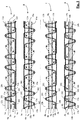
- the face-to-face woven fabric according to the figures is produced on a two rapier face-to-face weaving machine ( Figures 1 and 2 ) or on a three rapier face-to-face weaving machine ( Figures 3 , 4 and 5 ), whereby in each consecutive weft insertion cycle, two weft threads (101, 102), (201,202) or three weft threads (101, 102, 103 or 104) (201, 202, 203 or 204) are inserted above one another at respective weft insertion levels into a shed between warp threads (1a-14a),(1b-14b) of a series of warp thread systems, whereby each warp thread system comprises the following 14 warp threads:
- the weaving machine has a jacquard machine for positioning of the figure warp threads (1a-8a), (1b-8b).
- the other warp threads (9a, 10a), (9b, 10b), (11a, 12a, 13a, 14a), (11b, 12b, 13b, 14b) are positioned in each shed, for example by means of weaving frames.
- each warp thread (1a-14a),(1b-14b) is brought into each shed in such a position relative to the two or three weft insertion levels that the warp threads and the weft threads (101, 102), (201,202) inserted at the levels in the consecutive weft insertion cycles take up the relative positions shown schematically in the figures for the warp threads (la-14a),(1b-14b) of two warp thread systems lying alongside one another.
- these warp threads and weft threads thereby form two fabrics (I, II) above one another.
- the warp threads (la-14a), (lb-14b) of the different warp thread systems are always drawn through the reed openings between two dents of the weaving reed in the same order.
- the 14 warp threads of the different warp thread systems are hereby drawn in each case through a respective reed opening and separated from the warp threads of adjacent warp thread systems by the reed dents.
- the warp threads of each warp thread system can also be spread over two or more reed openings, or warp threads of several warp thread systems can be drawn together through the same reed opening.
- top sides of the fabrics are facing towards one another.
- the other side of each fabric is referred to as the back side.
- the top side of a fabric is also referred to in this patent application as a pattern side.
- weft threads (101, 201) that are brought in at the top insertion level during consecutive weft insertion cycles are bound into each warp thread system by two binding warp threads (11a, 12a), (11b, 12b) so that a top fabric (I) is formed.
- the weft threads (102, 202) that are brought in at the bottom insertion level during consecutive weft insertion cycles (or weaving cycles) are bound in each time under the top fabric by two other binding warp threads (13a, 14a), (13b, 14b) so that a bottom fabric (II) is formed. If three weft threads are inserted above one another in each weaving cycle, there is a top, a middle and a bottom insertion level.
- the one binding warp thread (11a) of each warp thread system runs alternately above two weft threads (201, 101) that are inserted at the top insertion level in a first and a following second weaving cycle (the weft threads furthest left in each cross section of the figures are inserted above one another during a first weaving cycle), and under two weft threads (201, 101) that are inserted at the top insertion level in a following third and a following fourth weaving cycle.
- the other binding warp thread (12a) runs alternately under the two weft threads (101, 201) of the first and second weaving cycle and over the two weft threads (101, 201) of the third and fourth weaving cycle. In the bottom fabric (II), this takes place in a corresponding manner for the two binding warp threads (13a, 14a) relative to the weft threads (102, 202) of the bottom fabric.
- the two binding warp threads (11b, 12b) in the top fabric (I) and the two binding warp threads (13b, 14b) in the bottom fabric (II) have an identical course relative to the respective weft threads (101, 201), (102, 202) in these fabrics.
- a tension warp thread (9a), (9b) in the top fabric is positioned alternately above the top insertion level and between the top insertion level and the insertion level below (the bottom or middle level, depending on whether there are two or three insertion levels), so that two consecutive weft threads (101, 201) in the top fabric (I) each run respectively above and below the taut tension warp thread (9a), (9b).
- another tension warp thread (10a), (10b) in the bottom fabric (II) is positioned alternately below the bottom insertion level and between the bottom insertion level and the insertion level above (the top or middle level, depending on whether there are two or three insertion levels), so that two consecutive weft threads (102, 202) in the bottom fabric (II) each run respectively above and below the taut tension warp thread (10a),(10b).
- weft threads (101, 201), (102, 202) of each fabric are divided over two levels, whereby alternately a weft thread (102), (201) on the top side and a weft thread (101), (202) on the back side runs relative to the tension warp threads (9a),(9b),(10a),(10b) of the fabric.
- the term 'outer weft' is also used for a weft thread running on the back side of the tension warp threads.
- a weft thread running on the top side of the tension warp threads is referred to as an 'inner weft'.
- the two weft threads that are bound into respective openings between two binding warp threads (11a, 12a), (11b, 12b); (13a, 14a), (13b, 14b) are each time bound in at different levels in the respective fabric.
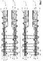
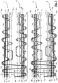
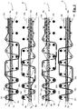
- the pattern is formed in these fabrics according to the different figures by means of figure warp threads that float on the fabric surface ( Figures 1 , 2 and 3 ), form cut pile ( Figures 2 , 3 and 5 ), form pile loops ( Figure 3 ), or form ribs ( Figures 4 and 5 ) or by combining several of these possibilities in the same fabric.
- figure warp threads (la-4a) with mutually differing colours are allocated to the top fabric (I) and four other figure warp threads (5a-8a) with four other mutually differing colours are allocated to the bottom fabric (II) in the first warp thread system (the top system in the figures).
- the figure warp threads allocated to a fabric are incorporated into this fabric when they are non-pattem-determining.
- the pattern in the fabrics in Figure 1 is determined in that on the top side of each fabric in each warp thread system, two figure warp threads (3a),(4a);(5a),(6a); (3b),(4b);(5b),(6b) have several parts that run (float) over a number of weft threads at the fabric surface.
- weft threads shown in the figures vertically above one another are each inserted during the same weaving cycle, and that the weft threads of the consecutive weaving cycles are shown in order from left to right in the figures.
- the figure warp threads are bound over a weft thread (201) on the back side of the fabric (I) immediately before they start to float and immediately after floating.
- figure warp threads are prevented from running parallel at the transition from their incorporated state to their floating state and vice versa.
- the one figure warp thread (3a),(6b) runs on the fabric surface over the weft threads of the third to seventh weaving cycle, while the other figure warp thread (4a), (5b) runs on the fabric surface over the weft threads of the fifth to ninth weaving cycle.
- the figure warp threads intersect one another so that they come to lie better alongside one another and there is less chance that they run over one another and mask one another.
- a pattern is formed on a right portion of the fabrics with two floating figure warp threads (1a), (2a) that run over several weft threads (101) on the fabric surface as described above.
- a figure warp thread (5a) with a first colour that is allocated to the bottom fabric is bound, from the first weaving cycle in consecutive weaving cycles, alternately over an outer weft (102) of the bottom fabric (II) and an outer weft (201) of the top fabric (I), and from the weft thread (102) of the fifth weaving cycle in the bottom fabric (II) is incorporated into this bottom fabric.
- a figure warp thread (4a) with a second colour that is allocated to the top fabric (I) is first incorporated into the top fabric (I) and then runs successively over the outer weft (201) of the sixth weaving cycle in the top fabric (I), the outer weft (102) of the seventh weaving cycle in the bottom fabric (II) and the outer weft (201) of the eighth weaving cycle in the top fabric (I) and is then incorporated back into the top fabric (I).
- a figure warp thread (4b) with the second colour that is now allocated to the bottom fabric (II) is bound, from the first weaving cycle in consecutive weaving cycles, alternately over an outer weft (102) of the bottom fabric and an outer weft (201) of the top fabric (I), and from the weft thread (102) of the fifth weaving cycle in the bottom fabric (II) is incorporated into this bottom fabric (II).
- a figure warp thread (5b) with the first colour that is now allocated to the top fabric (I) is first incorporated into the top fabric (I) and then runs successively over the outer weft (201) of the sixth weaving cycle in the top fabric (I), the outer weft (102) of the seventh weaving cycle in the bottom fabric (II) and the outer weft (201) of the eighth weaving cycle in the top fabric and is then incorporated back into the top fabric (I).
- the cut pile is formed in the warp thread systems lying alongside one another alternately with warp threads of a first colour and a second colour. In this way the appearance of the zone with cut pile is determined by a mixing effect of different colours. By making use of this mixing effect, a sharp demarcation of this zone is also possible.
- the first and also the last pile leg of this zone are indeed each bound over the same weft thread.
- the sawtooth pattern is prevented in that the figure warp threads that form a zone with cut pile are each allocated to the same fabric in the consecutive warp thread systems, and hence bound in at the edges of the pile zone into the same fabric over the same weft thread.
- the pile zone is formed by a combination of two different coloured figure warp threads (5a), (4b) and (4a), (5b).
- the pile zone exhibits a mixing effect determined by the colour combination. This allows a pile zone with a straight demarcation to be produced (without a sawtooth pattern) because the first and the last pile leg of each pile-forming figure warp thread of the warp thread systems are bound over the same weft thread. This last pile leg can have the one or the other colour, depending on the fabric and the warp thread system in question.
- a top lancet (L 1a ), (L 1b ) and a bottom lancet (L 2a ), (L 2b ) is provided in each warp thread system between the two fabrics being created during weaving.
- the face-to-face weaving machine is a three rapier weaving machine with a middle rapier that inserts a loop weft thread (103), (203) into a middle insertion level during the consecutive weaving cycles.
- the top and the bottom rapier each insert weft threads in a top and bottom insertion level, respectively, which together with the binding warp threads and the tension warp threads form a top and a bottom fabric as explained above.
- the pattern is formed in the fabrics from left to right by means of cut pile, pile loops and figure warp threads running on the fabric surface.
- a figure warp thread (4a) with a first colour that is allocated to the top fabric is alternately bound over an outer weft (102) of the bottom fabric (II) and over an outer weft (201) of the following weaving cycle into the top fabric (I). From the outer weft (201) of the fourth weaving cycle in the top fabric, this figure warp thread is incorporated into the top fabric.
- a figure warp thread (4b) with the first colour that is now allocated to the bottom fabric is alternately bound over an outer weft (102) of the bottom fabric (II) and over an outer weft (201) of the following weaving cycle into the top fabric (I). From the outer weft (102) of the fifth weaving cycle in the bottom fabric (II), this figure warp thread (4b) is incorporated into the bottom fabric.
- the figure warp thread (4b) that is allocated to the bottom fabric forms one pile leg more than the figure warp thread (4a) allocated to the top fabric.
- the first figure warp thread (4b) must indeed return from the fourth outer weft (201) in the top fabric (I) to the bottom fabric (II) in order to be incorporated there, and the other figure warp thread (4a) does not. Because the transition between pile formation and non-pile-forming incorporation (and vice versa) does not take place the same in the consecutive warp thread systems, the edges of a pile zone running in the weft direction have a more or less jagged course.
- figure warp threads (2a), (6a); (6b), (2b) are used to create pile loops in both fabrics.
- a figure warp thread (2a) with a first colour allocated to the top fabric is allowed to run immediately after binding over the outer weft (201) of the fourth weaving cycle, first forming a loop over two loop weft threads (103) of consecutive weaving cycles, this figure warp thread (4a) is then allowed to bind over an outer weft (201) of the following weaving cycle and then to run back forming a pile loop over one loop weft thread (103) of the following weaving cycle, to allow it to finally run taut after binding over an outer weft (201) into the top fabric between the weft threads bound on two levels.
- a figure warp thread (6a) with a second colour allocated to the bottom fabric is allowed to run in the bottom fabric, first forming a pile loop over two pile weft threads, and immediately thereafter forming a pile loop over one loop weft thread before being incorporated into the top fabric.
- a zone is formed in which other figure warp threads (1a),(8a); (8b),(1b) are pattern-determining since they float over one or more weft threads (101),(202) at the fabric surface.
- a figure warp thread (1a) with a first colour allocated to the top fabric and a figure warp thread (8a) with a second colour allocated to the bottom fabric are used for this.
- the colours are reversed: in the top and bottom fabric respectively, a figure warp thread (8b) with the second colour allocated to the top fabric and a figure warp thread (1b) with the first colour allocated to the bottom fabric are used.
- a three rapier face-to-face weaving machine is used, whereby the middle rapier inserts an additional weft thread (104), (204) at a middle insertion level in the consecutive weaving cycles.
- the top and the bottom rapier each insert weft threads in a top and bottom insertion level, respectively, that together with the binding warp threads (11a, 12a), (13a,14a), (11b,12b), (13b,14b) and the tension warp threads (9a, 10a), (9b, 10b) form a top (I) and a bottom (II) fabric as explained above.
- the additional weft threads (104),(204) are thicker than the other weft threads and run on the top sides of the fabrics facing towards one another and are not bound into the fabrics by binding warp threads.
- a figure warp thread (4a) with a first colour allocated to the top fabric is allowed to run alternately over an outer weft (101) of the top fabric (I) and a thicker additional weft thread (204) in the first warp thread system.
- this figure warp thread is incorporated from the outer weft of the fifth weaving cycle into the back side of the top fabric (I).
- This figure warp thread is furthermore used again to produce a wider rib over the thicker weft threads (204) that are inserted in the eighth and tenth weaving cycles, after which the figure warp thread (4a) is bound over an outer weft (101), and further is incorporated running taut between the weft threads (101),(201) bound in at two levels.
- a second figure warp thread (1a) with a second colour allocated to the top fabric is allowed to form a wider rib in the top fabric (I) over the thicker weft threads (204) inserted in the sixth and eighth weaving cycles.
- a figure warp thread (5a) with a third colour allocated to the bottom fabric is first allowed to form two ribs in the bottom fabric (II) over the thicker weft threads (104) inserted in the first and third weaving cycle, and to then form a wider rib over the weft threads (104) inserted in the seventh and ninth weaving cycle, and a figure warp thread (8a) with a fourth colour allocated to the bottom fabric is also allowed to form a wider rib over the weft threads (104) inserted in the fifth and seventh weaving cycle.
- the thicker weft threads (104),(204) are not masked by figure warp threads, so that these run clearly visibly on the fabric surface and can create an additional pattern-determining effect in the fabrics with their colour and thickness.
- a three rapier face-to-face weaving machine is also used, whereby the middle rapier inserts an additional thicker weft thread (104), (204) in the consecutive weaving cycles as in the method according to Figure 4 .
- Two pile zones with cut pile are formed in the fabric with an intermediate zone where ribs are formed in the manner described by reference to Figure 4 .
- the ribs are formed in the top fabric using figure warp threads (2a),(1a) with a first and a second colour, respectively, and in the bottom fabric using figure warp threads (7a),(8a) with a third and a fourth colour, respectively. In the second warp thread system, these colours are reversed.
- a figure warp thread (5a) with a certain colour allocated to the top fabric is bound in alternately over an outer weft (102) of the top fabric (I) and over an outer weft of the bottom fabric (II) in the first warp thread system.
- a figure warp thread (5b) with the same colour that now is allocated to the top fabric is alternately bound into the top fabric (I) over an outer weft (102) of the bottom fabric (II) and over an outer weft of the top fabric (I). Because these figure warp threads are incorporated alternately into the top fabric and into the bottom fabric in consecutive warp thread systems, the demarcation of the pile zone is not perfectly straight (sawtooth pattern) as explained above by reference to Figure 3 .
- pile is formed in the same way in the first warp thread system by a figure warp thread (3a) with a certain colour allocated to the top fabric, and in the second warp thread system pile is formed by a pile warp thread with the same colour allocated to the bottom fabric.
- a sawtooth pattern is formed again here.
- the figure warp threads running between the two fabrics are then cut between the two fabrics so that upright pile legs or cut pile are formed on the fabrics.
- Sawtooth forming can be prevented by the use of a method according to Figure 2 or by providing a separate figure warp thread in each warp thread system for the formation of cut pile, whereby the respective separate figure warp threads are always incorporated into the same fabric by the consecutive warp thread systems.
- the additional thicker weft threads (104), (204) are more or less visible between the pile legs of the fabrics and form a background effect in these pile zones.
- fabrics can be woven with a particularly large variation in appearance in relation to the number of figure warp threads per warp thread system, whereby by preference it is not only the appearance (such as the colour) of the figure warp threads themselves that provide the variation, but also the variation in the fabric structure, such as i.a. the presence of floating figure warp threads or a rib structure, pile loops or cut pile produced by means of these figure warp threads, or by a combination of two or more of these possibilities, whether or not in combination with a weft effect.
Claims (11)
- Verfahren zur Herstellung von Geweben (I, II), die zumindest teilweise florfrei sind, wobei bei jedem von aufeinander folgenden Schusseintragszyklen auf einer Doppelwebmaschine ein oder mehrere Schussfäden (101-104), (201-204) in ein Fach zwischen Kettfäden (la-14a, lb-14b) einer Anzahl von Kettfadensystemen, die nebeneinander liegen, eingetragen werden, wobei jedes Kettfadensystem (la-14a), (1b-14b) einen oder mehrere Figurkettfäden (la-8a), (1b-8b) umfasst, wobei jeder Figurkettfaden zu einem der Gewebe (I, II) zugeordnet ist und wobei die Kettfäden (la-14a), (1b-14b) in jedem Fach in einer Weise positioniert sind, dass zwei Gewebe (I, II) übereinander gewebt werden, mit zumindest einer florfreien Zone, in der jeder Figurkettfaden (la-8a), (1b-8b), der einem gewünschten Muster entspricht, entweder musterbestimmend in dem Gewebe ist, zu dem dieser Figurkettfaden zugeordnet ist, oder in dieses Gewebe (I, II) in einer nicht-musterbestimmenden Weise eingebunden ist, dadurch gekennzeichnet, dass in zumindest einem Paar (1a-14a, 1b-14b) von zwei Kettfadensystemen, die nebeneinander liegen, zwei oder mehr Sätze (1a, 1b), (2a, 2b),..., (8a, 8b) von zwei Figurkettfäden mit dem gleichen Erscheinungsbild bereitgestellt sind, wobei das Erscheinungsbild der Figurkettfäden jedes Satzes verschieden von dem Erscheinungsbild der Figurkettfäden jedes anderen Satzes ist, wobei die Figurkettfäden mit dem gleichen Erscheinungsbild jedes Satzes (1a, 1b), (2a, 2b), ..., (8a, 8b) zu einem unterschiedlichen Kettfadensystem (la-14a), (1b-14b) des Paares gehören und, entsprechend, zu einem unterschiedlichen Gewebe (I, II) zugeordnet sind, sodass für jeden Satz (1a, 1b), (2a, 2b), ..., (8a, 8b) aus zwei Figurkettfäden mit dem gleichen Erscheinungsbild, pro Paar von Kettfadensystemen, ein Figurkettfaden mit dem Erscheinungsbild in beiden Geweben (I, II) verfügbar ist, um das Muster in der bzw. den florfreien Zone (n) zu bestimmen.
- Verfahren zur Herstellung von Geweben nach Anspruch 1, dadurch gekennzeichnet, dass in zumindest einem Paar der zwei Kettfadensysteme, die nebeneinander liegen, zumindest einer der Figurkettfäden (1a-8a), (1b-8b) der Sätze alternierend in das eine oder in das andere Gewebe über zumindest einem Schussfaden (102), (201) gebunden ist und dann zwischen den Geweben (I, II) geschnitten wird, sodass zumindest eine Florzone in jedem Gewebe erzeugt wird und/oder dass eine Anzahl von Kettfadensystemen (la-14a), (1b-14b) zumindest einen zusätzlichen Figurkettfaden umfasst, der nicht zu einem Satz (1a, 1b), (2a, 2b), ..., (8a, 8b) von Figurkettfäden gehört und der alternierend in das eine und das andere Gewebe über zumindest einem Schussfaden (102), (201) gebunden ist und dann zwischen den Geweben(I, II) geschnitten wird, sodass zumindest eine Florzone in jedem Gewebe erzeugt wird.
- Verfahren zur Herstellung von Geweben nach einem der obigen Ansprüche, dadurch gekennzeichnet, dass jedes Kettfadensystem n Figurkettfäden mit paarweise unterschiedlichem Erscheinungsbild umfasst, wobei n eine gerade Zahl ist und wobei jeder Figurkettfaden zu einem entsprechenden Satz von Figurkettfäden gehört, und dadurch, dass in jedem Paar aus einem ersten (la-14a) und einem zweiten Kettfadensystem (1b-14b), die nebeneinander liegen,
im ersten Kettfadensystem (la-14a),- n/2 Figurkettfäden (la-4a) zum oberen Gewebe (I) zugeordnet werden, und- n/2 andere Figurkettfäden (5a-8a) zum unteren Gewebe (II) zugeordnet werden, und
im zweiten Kettfadensystem (1b-14b),- n/2 Figurkettfäden (5b-8b) mit dem gleichen Erscheinungsbild wie die Figurkettfäden, die dem unteren Gewebe (II) im ersten Kettfadensystem (la-14a) zugeordnet wurden, dem oberen Gewebe (I) zugeordnet werden, und- n/2 Figurkettfäden (1b-4b) mit dem gleichen Erscheinungsbild wie die Figurkettfäden, die dem oberen Gewebe (I) im ersten Kettfadensystem (la-14a) zugeordnet wurden, dem unteren Gewebe (II) zugeordnet werden. - Verfahren zur Herstellung von Geweben nach Anspruch 3, dadurch gekennzeichnet, dass n = 8 und dass die acht Figurkettfäden (la-8a), (1b-8b) von jedem Paar aus einem ersten (la-14a) und einem zweiten (1b-14b) Kettfadensystem, die nebeneinander liegen, zu den Geweben (I, II) entsprechend einem der folgenden Zuordnungspläne (a-d) zugeordnet werden, wobei die Zuordnung jedes dieser acht Figurkettfäden mit einem ersten, zweiten, dritten, ..., achten Erscheinungsbild immer in jedem Zuordnungsplan für beide Kettfadensysteme in der gleichen Reihenfolge mittels einer Abfolge von acht Buchstaben T oder B angezeigt wird, wobei T das obere Gewebe und B das untere Gewebe anzeigt:
Zuordnungsplan Erstes Kettfadensystem Zweites Kettfadensystem 1 2 3 4 5 6 7 8 1 2 3 4 5 6 7 8 A T B T B B T B T B T B T T B T B B T T T T B B B B B B B B T T T T C T T B B B B T T B B T T T T B B D B T T B B T T B T B B T T B B T - Verfahren zur Herstellung von Geweben nach einem der obigen Ansprüche, dadurch gekennzeichnet, dass die Kettfäden (la-14a), (1b-14b) in jedem Fach in einer Weise positioniert sind, dass zwei Gewebe (I, II) übereinander gewebt sind, mit zumindest einem Figurkettfaden (la-8a),(1b-8b) in der bzw. den genannten Zone(n), der musterbestimmend über zumindest einem Schussfaden (101), (202) des entsprechenden Gewebes an der Gewebeoberfläche läuft.
- Verfahren zur Herstellung von Geweben nach einem der obigen Ansprüche, dadurch gekennzeichnet, dass zumindest ein zusätzlicher Schussfaden (104), (204) in einer Anzahl von Schusseintragszyklen eingetragen wird, und dass die Kettfäden (la-14a), (1b-14b) in jedem Fach in einer Weise positioniert sind, dass zwei Gewebe (I, II) übereinander gewebt werden, mit einem oder mehreren zusätzlichen Schussfäden (104), (204) in der bzw. den Zone (n), die vorwiegend an der Gewebeoberfläche laufen, und mit zumindest einem Figurkettfaden (la-8a), (1b-8b) in der bzw. den Zone (n), der über den zumindest einen zusätzlichen Schussfaden (104), (204) läuft, um eine Rippe zu bilden.
- Verfahren zur Herstellung von Geweben nach einem der obigen Ansprüche, dadurch gekennzeichnet, dass einer ersten Herstellungsphase, in der jeder Figurkettfaden (la-8a, lb-8b) zu einem der Gewebe (I, II) entsprechend einem ersten Zuordnungsplan zugeordnet ist, eine zweite Herstellungsphase folgt, in der jeder Figurkettfaden (la-8a, lb-8b) zu einem der Gewebe (I, II) entsprechend einem zweiten Zuordnungsplan zugeordnet ist, und dass die Figurkettfäden, die entsprechend dem zweiten Zuordnungsplan zu einem unterschiedlichen Gewebe im Vergleich zum ersten Zuordnungsplan zugeordnet sind, florbildend zwischen den zwei Herstellungsphasen zu dem anderen Gewebe gebracht werden, und vorzugsweise Flor in einem Übergangsgewebe bilden, das später entfernt wird.
- Doppelwebmaschine, die Folgendes umfasst:- eine Anzahl von Kettfadensystemen (la-14a), (1b-14b), die nebeneinander liegen, von denen jedes einen oder mehrere Figurkettfäden (la-8a), (1b-8b) umfasst,- Schusseintragsvorrichtungen, bereitgestellt zum Eintragen von einem oder mehreren Schussfäden (101-104), (201-204) in ein Fach zwischen den Kettfäden (la-14a, 1b-14b) in jedem der aufeinander folgenden Schusseintragszyklen, und- fachbildende Vorrichtungen, bereitgestellt zum Positionieren der Kettfäden (la-14a, lb-14b) in jedem Fach, und um so jeden Figurkettfaden zu einem der Gewebe (I, II) zuzuordnen,- sodass zwei zumindest teilweise florfreie Gewebe (I, II) übereinander gewebt werden, mit zumindest einer florfreien Zone, in der jeder Figurkettfaden (la-8a), (1b-8b) entsprechend einem gewünschten Muster entweder musterbestimmend in dem Gewebe ist, zu dem dieser Figurkettfaden zugeordnet ist, oder in dieses Gewebe (I, II) in einer nicht-musterbestimmenden Weise eingebunden ist, dadurch gekennzeichnet, dass in zumindest einem Paar (la-14a, lb-14b) aus zwei Kettfadensystemen, die nebeneinander liegen, zwei oder mehr Sätze (1a, 1b), (2a, 2b), ..., (8a, 8b) aus zwei Figurkettfäden mit dem gleichen Erscheinungsbild bereitgestellt sind, wobei das Erscheinungsbild der Figurkettfäden jedes Satzes verschieden von dem Erscheinungsbild der Figurkettfäden jedes anderen Satzes ist, wobei die Figurkettfäden mit dem gleichen Erscheinungsbild aus jedem Satz (1a, 1b), (2a, 2b), ..., (8a, 8b) zu einem unterschiedlichen Kettfadensystem (la-14a), (1b-14b) des Paares gehören,- und dass die fachbildenden Vorrichtungen bereitgestellt sind, um die zwei Figurkettfäden jedes Satzes zu einem unterschiedlichen Gewebe (I, II) zuzuordnen,sodass für jeden Satz (1a, 1b), (2a, 2b), ..., (8a, 8b) von zwei Figurkettfäden mit dem gleichen Erscheinungsbild, pro Paar von Kettfadensystemen, ein Figurkettfaden mit dem Erscheinungsbild in beiden Geweben (I, II) verfügbar ist, um das Muster in der bzw. den florfreien Zone(n) zu bestimmen.
- Doppelwebmaschine nach Anspruch 8, dadurch gekennzeichnet, dass jedes Kettfadensystem n Figurkettfäden mit paarweise unterschiedlichem Erscheinungsbild umfasst, wobei n eine gerade Zahl ist und wobei jeder Figurkettfaden zu einem entsprechenden Satz von Figurkettfäden gehört, und dadurch, dass in jedem Paar aus einem ersten (la-14a) und einem zweiten Kettfadensystem (1b-14b), die nebeneinander liegen, im ersten Kettfadensystem (la-14a),- n/2 Figurkettfäden (la-4a) zum oberen Gewebe (I) zugeordnet werden, und- n/2 andere Figurkettfäden (5a-8a) zum unteren Gewebe (II) zugeordnet werden, und
im zweiten Kettfadensystem (1b-14b),- n/2 Figurkettfäden (5b-8b) mit dem gleichen Erscheinungsbild wie die Figurkettfäden, die dem unteren Gewebe (II) im ersten Kettfadensystem (la-14a) zugeordnet wurden, dem oberen Gewebe (I) zugeordnet werden, und- n/2 Figurkettfäden (1b-4b) mit dem gleichen Erscheinungsbild wie die Figurkettfäden, die dem oberen Gewebe (I) im ersten Kettfadensystem (la-14a) zugeordnet wurden, dem unteren Gewebe (II) zugeordnet werden. - Doppelwebmaschine nach Anspruch 9, dadurch gekennzeichnet, dass n = 8 und dass die acht Figurkettfäden (la-8a), (1b-8b) von jedem Paar aus einem ersten (la-14a) und einem zweiten (1b-14b) Kettfadensystem, die nebeneinander liegen, zu den Geweben (I, II) entsprechend einem der folgenden Zuordnungspläne (a-d) zugeordnet werden, wobei die Zuordnung jedes dieser acht Figurkettfäden mit einem ersten, zweiten, dritten, ..., achten Erscheinungsbild immer in jedem Zuordnungsplan für beide Kettfadensysteme in der gleichen Reihenfolge mittels einer Abfolge von acht Buchstaben T oder B angezeigt wird, wobei T das obere Gewebe und B das untere Gewebe anzeigt:
Zuordnungsplan Erstes Kettfadensystem Zweites Kettfadensystem 1 2 3 4 5 6 7 8 1 2 3 4 5 6 7 8 A T B T B B T B T B T B T T B T B B T T T T B B B B B B B B T T T T C T T B B B B T T B B T T T T B B D B T T B B T T B T B B T T B B T - Doppelwebmaschine nach einem der Ansprüche 8 bis 10, dadurch gekennzeichnet, dass sie für einen Betrieb mit einem Verfahren nach einem oder mehreren der Ansprüche 1 bis 7 bereitgestellt ist.
Applications Claiming Priority (2)
| Application Number | Priority Date | Filing Date | Title |
|---|---|---|---|
| BE2015/0263A BE1023598B1 (nl) | 2015-11-10 | 2015-11-10 | Werkwijze voor het dubbelstukweven van weefsels met figuurkettingdraden |
| PCT/IB2016/001608 WO2017081530A1 (en) | 2015-11-10 | 2016-11-10 | Method for face-to-face weaving of fabrics with figure warp threads |
Publications (2)
| Publication Number | Publication Date |
|---|---|
| EP3374552A1 EP3374552A1 (de) | 2018-09-19 |
| EP3374552B1 true EP3374552B1 (de) | 2021-08-04 |
Family
ID=55236084
Family Applications (1)
| Application Number | Title | Priority Date | Filing Date |
|---|---|---|---|
| EP16816383.0A Active EP3374552B1 (de) | 2015-11-10 | 2016-11-10 | Verfahren zum doppelweben von stoffen mit figurkettfäden |
Country Status (5)
| Country | Link |
|---|---|
| US (1) | US10724160B2 (de) |
| EP (1) | EP3374552B1 (de) |
| CN (1) | CN108350625B (de) |
| BE (1) | BE1023598B1 (de) |
| WO (1) | WO2017081530A1 (de) |
Families Citing this family (4)
| Publication number | Priority date | Publication date | Assignee | Title |
|---|---|---|---|---|
| EP3702500B1 (de) * | 2019-02-26 | 2022-04-06 | STÄUBLI BAYREUTH GmbH | Verfahren zum weben von florgeweben und nach diesem verfahren gewebtes florgewebe |
| CN110129952B (zh) * | 2019-06-27 | 2020-06-09 | 江苏盛泰克纺织印染有限公司 | 一种双面阴影提花丝绒及其织造方法 |
| CN112210871A (zh) * | 2019-09-17 | 2021-01-12 | 滨州亚光家纺有限公司 | 一种双面异花毛巾 |
| US11339534B2 (en) * | 2019-09-18 | 2022-05-24 | Huyck Licensco Inc. | Multi-layer warp bound papermaker's forming fabrics |
Citations (8)
| Publication number | Priority date | Publication date | Assignee | Title |
|---|---|---|---|---|
| US1795157A (en) | 1928-04-13 | 1931-03-03 | Jr John Zimmermann | Double-pile fabric |
| DE550486C (de) | 1926-05-23 | 1932-05-18 | Christiane Sidonie Rosa Clavie | Verfahren zur Herstellung von gemusterten Jacquard-Doppelplueschgeweben |
| DD286939A7 (de) | 1988-04-28 | 1991-02-14 | Cheminitzer Webmaschinenbau Gmbh,De | Anordnung der polfaeden innerhalb des webblattes |
| BE1003830A5 (fr) | 1989-06-13 | 1992-06-23 | Chemnitzer Webmaschb Gmbh | Procede de preparation de tissus doubles, en particulier de tapis doubles. |
| EP1046734A2 (de) | 1999-04-21 | 2000-10-25 | SCHÖNHERR Textilmaschinenbau GmbH | Verfahren zur Herstellung von Doppelteppichgewebe |
| EP1072705A1 (de) | 1999-07-19 | 2001-01-31 | NV Michel van de Wiele | Verfahren zum Weben von Doppelstück-falsche Plüschgewebe mit geschnittener Flor und nach diesem Verfahren hergestelltes Gewebe |
| EP1666651A2 (de) | 2004-12-02 | 2006-06-07 | NV Michel van de Wiele | Verfahren zum Weben von Geweben und Hochpolgewebe |
| EP1785514A2 (de) | 2005-11-10 | 2007-05-16 | NV Michel van de Wiele | Verfahren zum Weben von Geweben mit Bereichen von Cordsamt mit einer grossen Vielfalt von Farbeffekten |
Family Cites Families (35)
| Publication number | Priority date | Publication date | Assignee | Title |
|---|---|---|---|---|
| US395462A (en) * | 1889-01-01 | taylor | ||
| US698743A (en) * | 1901-10-03 | 1902-04-29 | Joseph S Mac Elroy | Woven figured fabric. |
| US808976A (en) * | 1905-01-12 | 1906-01-02 | Thomas Benton Dornan | Woven fabric. |
| US2060502A (en) * | 1933-04-12 | 1936-11-10 | Collins & Aikman Corp | Method of weaving pile fabrics |
| US2108046A (en) * | 1934-09-01 | 1938-02-15 | Collins & Aikman Corp | Pile fabric and method of making the same |
| US2095382A (en) * | 1935-03-14 | 1937-10-12 | Collins & Aikman Corp | Method of weaving frieze pile fabrics |
| US2182610A (en) * | 1936-11-09 | 1939-12-05 | Calonnier Maurice | Manufacture of velvet woven in double piece |
| FR1401236A (fr) * | 1964-03-04 | 1965-06-04 | Librex Anstalt | Nouveau tapis tissé en double pièce et mode de tissage de ce tapis |
| US3519032A (en) * | 1968-02-09 | 1970-07-07 | Librex Anstalt | Pile fabrics |
| US4197345A (en) * | 1978-09-05 | 1980-04-08 | Engineered Yarns, Inc. | Fabric having multiple solid colored stripes |
| US4848412A (en) * | 1988-02-23 | 1989-07-18 | Milliken Research Corporation | Patterned woven fabric |
| BE1004348A3 (nl) * | 1990-06-05 | 1992-11-03 | Wiele Michel Van De Nv | Werkwijze voor het vervaardigen van een dubbelstuktapijtweefsel, in een 2-schotbinding alsmede aldus verkregen weefsels. |
| BE1004894A4 (nl) * | 1991-05-21 | 1993-02-16 | Wiele Michel Van De Nv | Werkwijze voor het vervaardigen van een dubbelstuktapijtweefsel in een enkelspoelige binding alsmede aldus verkregen weefsels. |
| JP2890175B2 (ja) * | 1995-05-10 | 1999-05-10 | 日清紡績株式会社 | 織成方法 |
| BE1011348A3 (nl) * | 1997-09-02 | 1999-07-06 | Wiele Michel Van De Nv | Werkwijze voor het weven van dubbelstuktapijten en tapijtweefsels met verbeterde eigenschappen. |
| BE1012077A3 (nl) * | 1998-07-22 | 2000-04-04 | Wiele Michel Van De Nv | Onechte en echte boucle-weefsels, en een werkwijze voor de productie van dergelijke weefsels. |
| BE1011362A3 (nl) * | 1998-07-22 | 1999-07-06 | Wiele Michel Van De Nv | Werkwijze voor het vervaardigen van weefsels met aan beide zijden een ribstructuur, en volgens deze werkwijze vervaardigde weefsels. |
| BE1012269A3 (nl) * | 1998-11-06 | 2000-08-01 | Wiele Michel Van De Nv | Werkwijze voor de vervaardiging van een weefsel met ribstructuur, en volgens deze werkwijze vervaardigde weefsels. |
| BE1013266A3 (nl) * | 2000-02-02 | 2001-11-06 | Wiele Michel Van De Nv | Werkwijze voor het vervaardigen van een hoogkorig poolweefsel. |
| DE60124813T2 (de) * | 2000-05-02 | 2007-10-11 | N.V. Michel Van De Wiele, Kortrijk | Verfahren zum Herstellen von Doppelstück Plüschgewebe und nach diesem Verfahren hergestelltes Gewebe |
| BE1015103A3 (nl) * | 2002-09-11 | 2004-10-05 | Wiele Michel Van De Nv | Werkwijze voor het weven van een poolweefsel. |
| BE1016008A4 (nl) * | 2004-05-07 | 2006-01-10 | Wiele Michel Van De Nv | Werkwijze en inrichting voor het weven van dubbelzijdig bruikbare weefsels. |
| BE1016295A3 (nl) * | 2004-11-04 | 2006-07-04 | Wiele Michel Van De Nv | Werkwijze en inrichting voor het weven van weefsels voorzien van zones met vlottende pool over meerdere inslagdraden. |
| BE1016336A5 (nl) * | 2004-12-02 | 2006-08-01 | Wiele Michel Van De Nv | Werkwijze voor het weven van dubbelstukweefsels, weefsel geweven volgens een dergelijke werkwijze en dubbelstukweefmachine voorzien voor het uitvoeren van een dergelijke werkwijze. |
| US7207355B2 (en) * | 2005-05-06 | 2007-04-24 | Astenjohnson, Inc. | Multi-axial seamed papermaking fabric and method |
| US7520303B2 (en) * | 2005-06-24 | 2009-04-21 | N.V. Michel Van De Wiele | Method for weaving a fabric, fabric woven by means of such a method and weaving machine for weaving such a fabric |
| US7644737B2 (en) * | 2005-09-02 | 2010-01-12 | Textilma Ag | Method for production of a velvet ribbon with double-sided nap and ribbon weaving machine for carrying out said method |
| BE1016883A3 (nl) * | 2005-12-06 | 2007-09-04 | Wiele Michel Van De Nv | Werkwijze voor het vervaardigen van poolweefsels met hoge dichtheid. |
| EP1900861B1 (de) * | 2006-09-05 | 2015-07-08 | NV Michel van de Wiele | Verfahren zum Weben eines Gewebes und mit diesem Verfahren gewebtes Gewebe |
| BE1017560A3 (nl) * | 2007-04-18 | 2008-12-02 | Wiele Michel Van De Nv | Geweven kunstgrasmat met fijne poolverdeling. |
| EP2251467B1 (de) * | 2009-05-13 | 2013-08-07 | SCHÖNHERR Textilmaschinenbau GmbH | Verfahren zum gleichzeitigen Weben von zwei Gewebe, Gewebe das mit einem solchen Verfahren gewebt wird und Webmaschine bei der dieses Verfahren anwendbar ist. |
| US7841369B1 (en) * | 2009-11-18 | 2010-11-30 | vParadox LLC | Weaving process for production of a full fashioned woven stretch garment with load carriage capability |
| BE1020430A3 (nl) * | 2011-12-23 | 2013-10-01 | Wiele Michel Van De Nv | Werkwijze voor het weven van een poolweefsel met poolvrije zones. |
| BE1022393B1 (nl) * | 2013-01-10 | 2016-03-21 | Nv Michel Van De Wiele | Werkwijze voor het weven van poolweefsels en werkwijze voor het daarvoor uitrusten van een weefmachine |
| US9534323B1 (en) * | 2016-01-09 | 2017-01-03 | Trident Limited | Terry fabric weave and resulting terry fabric |
-
2015
- 2015-11-10 BE BE2015/0263A patent/BE1023598B1/nl active
-
2016
- 2016-11-10 WO PCT/IB2016/001608 patent/WO2017081530A1/en active Application Filing
- 2016-11-10 CN CN201680065421.XA patent/CN108350625B/zh active Active
- 2016-11-10 US US15/775,380 patent/US10724160B2/en active Active
- 2016-11-10 EP EP16816383.0A patent/EP3374552B1/de active Active
Patent Citations (8)
| Publication number | Priority date | Publication date | Assignee | Title |
|---|---|---|---|---|
| DE550486C (de) | 1926-05-23 | 1932-05-18 | Christiane Sidonie Rosa Clavie | Verfahren zur Herstellung von gemusterten Jacquard-Doppelplueschgeweben |
| US1795157A (en) | 1928-04-13 | 1931-03-03 | Jr John Zimmermann | Double-pile fabric |
| DD286939A7 (de) | 1988-04-28 | 1991-02-14 | Cheminitzer Webmaschinenbau Gmbh,De | Anordnung der polfaeden innerhalb des webblattes |
| BE1003830A5 (fr) | 1989-06-13 | 1992-06-23 | Chemnitzer Webmaschb Gmbh | Procede de preparation de tissus doubles, en particulier de tapis doubles. |
| EP1046734A2 (de) | 1999-04-21 | 2000-10-25 | SCHÖNHERR Textilmaschinenbau GmbH | Verfahren zur Herstellung von Doppelteppichgewebe |
| EP1072705A1 (de) | 1999-07-19 | 2001-01-31 | NV Michel van de Wiele | Verfahren zum Weben von Doppelstück-falsche Plüschgewebe mit geschnittener Flor und nach diesem Verfahren hergestelltes Gewebe |
| EP1666651A2 (de) | 2004-12-02 | 2006-06-07 | NV Michel van de Wiele | Verfahren zum Weben von Geweben und Hochpolgewebe |
| EP1785514A2 (de) | 2005-11-10 | 2007-05-16 | NV Michel van de Wiele | Verfahren zum Weben von Geweben mit Bereichen von Cordsamt mit einer grossen Vielfalt von Farbeffekten |
Also Published As
| Publication number | Publication date |
|---|---|
| US10724160B2 (en) | 2020-07-28 |
| BE1023598A1 (nl) | 2017-05-11 |
| EP3374552A1 (de) | 2018-09-19 |
| CN108350625A (zh) | 2018-07-31 |
| US20180371652A1 (en) | 2018-12-27 |
| WO2017081530A1 (en) | 2017-05-18 |
| BE1023598B1 (nl) | 2017-05-11 |
| CN108350625B (zh) | 2021-10-15 |
Similar Documents
| Publication | Publication Date | Title |
|---|---|---|
| EP3374552B1 (de) | Verfahren zum doppelweben von stoffen mit figurkettfäden | |
| US9080266B2 (en) | Method for weaving a pile fabric | |
| US9816209B2 (en) | Method of weaving of a pile fabric with pile-free zones | |
| US10233573B2 (en) | Carpet having a shadow effect and method for weaving a carpet fabric having a shadow effect | |
| EP2943604B1 (de) | Verfahren zum weben von florstoffen und zum konfigurieren einer webmaschine dafür | |
| US20010050112A1 (en) | Method for face-to-face weaving pile fabrics and pile fabrics woven according to this method | |
| CN109440267B (zh) | 一种高低毛隐纬缎档组织毛巾及其织造工艺 | |
| CN109837639B (zh) | 一种五经花罗的织造方法 | |
| RU2341598C1 (ru) | Интерлочный трикотаж с продольными цветными полосами | |
| CN205741421U (zh) | 一种波浪纹花式组织面料 | |
| CN220619279U (zh) | 一种幻色梭织面料、鞋面及鞋 | |
| CN217351690U (zh) | 一种色织条格底牛仔面料 | |
| CN216765183U (zh) | 机织变化富贵阁组织 | |
| CN216074180U (zh) | 具有立体花型的亲肤双层面料 | |
| CN212375468U (zh) | 一种多彩混合晕色丝绒带 | |
| CN205856734U (zh) | 一种线条定位提花布料 | |
| CN113818119A (zh) | 一种花纹组织、两层或多层布及其织造工艺 | |
| CN117328186A (zh) | 一种双面全异提花织物的设计制造方法 | |
| KR20240047788A (ko) | 신발갑피의 수율 향상을 위한 자카드 직기를 이용한 신발갑피 무늬가 형성된 자카드 직물의 제직방법 | |
| CN204356482U (zh) | 一种双锥体结构的立体织物 | |
| CN116676701A (zh) | 一种幻色梭织面料及其制备工艺、鞋面及鞋 | |
| CN102899774B (zh) | 可控柔刚度的织物 | |
| RU2374366C1 (ru) | Способ получения двухслойных тканей | |
| CN111364145A (zh) | 一种沙发布的织造方法 | |
| CN112501748A (zh) | 一种多工艺丝织面料及织法 |
Legal Events
| Date | Code | Title | Description |
|---|---|---|---|
| STAA | Information on the status of an ep patent application or granted ep patent |
Free format text: STATUS: UNKNOWN |
|
| STAA | Information on the status of an ep patent application or granted ep patent |
Free format text: STATUS: THE INTERNATIONAL PUBLICATION HAS BEEN MADE |
|
| PUAI | Public reference made under article 153(3) epc to a published international application that has entered the european phase |
Free format text: ORIGINAL CODE: 0009012 |
|
| STAA | Information on the status of an ep patent application or granted ep patent |
Free format text: STATUS: REQUEST FOR EXAMINATION WAS MADE |
|
| 17P | Request for examination filed |
Effective date: 20180601 |
|
| AK | Designated contracting states |
Kind code of ref document: A1 Designated state(s): AL AT BE BG CH CY CZ DE DK EE ES FI FR GB GR HR HU IE IS IT LI LT LU LV MC MK MT NL NO PL PT RO RS SE SI SK SM TR |
|
| AX | Request for extension of the european patent |
Extension state: BA ME |
|
| DAV | Request for validation of the european patent (deleted) | ||
| DAX | Request for extension of the european patent (deleted) | ||
| STAA | Information on the status of an ep patent application or granted ep patent |
Free format text: STATUS: EXAMINATION IS IN PROGRESS |
|
| 17Q | First examination report despatched |
Effective date: 20200506 |
|
| STAA | Information on the status of an ep patent application or granted ep patent |
Free format text: STATUS: EXAMINATION IS IN PROGRESS |
|
| GRAP | Despatch of communication of intention to grant a patent |
Free format text: ORIGINAL CODE: EPIDOSNIGR1 |
|
| STAA | Information on the status of an ep patent application or granted ep patent |
Free format text: STATUS: GRANT OF PATENT IS INTENDED |
|
| INTG | Intention to grant announced |
Effective date: 20210309 |
|
| RAP3 | Party data changed (applicant data changed or rights of an application transferred) |
Owner name: VANDEWIELE NV |
|
| GRAS | Grant fee paid |
Free format text: ORIGINAL CODE: EPIDOSNIGR3 |
|
| GRAA | (expected) grant |
Free format text: ORIGINAL CODE: 0009210 |
|
| STAA | Information on the status of an ep patent application or granted ep patent |
Free format text: STATUS: THE PATENT HAS BEEN GRANTED |
|
| AK | Designated contracting states |
Kind code of ref document: B1 Designated state(s): AL AT BE BG CH CY CZ DE DK EE ES FI FR GB GR HR HU IE IS IT LI LT LU LV MC MK MT NL NO PL PT RO RS SE SI SK SM TR |
|
| REG | Reference to a national code |
Ref country code: GB Ref legal event code: FG4D |
|
| REG | Reference to a national code |
Ref country code: AT Ref legal event code: REF Ref document number: 1417084 Country of ref document: AT Kind code of ref document: T Effective date: 20210815 |
|
| REG | Reference to a national code |
Ref country code: CH Ref legal event code: EP |
|
| REG | Reference to a national code |
Ref country code: DE Ref legal event code: R096 Ref document number: 602016061710 Country of ref document: DE |
|
| REG | Reference to a national code |
Ref country code: IE Ref legal event code: FG4D |
|
| REG | Reference to a national code |
Ref country code: LT Ref legal event code: MG9D |
|
| REG | Reference to a national code |
Ref country code: NL Ref legal event code: MP Effective date: 20210804 |
|
| REG | Reference to a national code |
Ref country code: AT Ref legal event code: MK05 Ref document number: 1417084 Country of ref document: AT Kind code of ref document: T Effective date: 20210804 |
|
| PG25 | Lapsed in a contracting state [announced via postgrant information from national office to epo] |
Ref country code: LT Free format text: LAPSE BECAUSE OF FAILURE TO SUBMIT A TRANSLATION OF THE DESCRIPTION OR TO PAY THE FEE WITHIN THE PRESCRIBED TIME-LIMIT Effective date: 20210804 Ref country code: AT Free format text: LAPSE BECAUSE OF FAILURE TO SUBMIT A TRANSLATION OF THE DESCRIPTION OR TO PAY THE FEE WITHIN THE PRESCRIBED TIME-LIMIT Effective date: 20210804 Ref country code: BG Free format text: LAPSE BECAUSE OF FAILURE TO SUBMIT A TRANSLATION OF THE DESCRIPTION OR TO PAY THE FEE WITHIN THE PRESCRIBED TIME-LIMIT Effective date: 20211104 Ref country code: HR Free format text: LAPSE BECAUSE OF FAILURE TO SUBMIT A TRANSLATION OF THE DESCRIPTION OR TO PAY THE FEE WITHIN THE PRESCRIBED TIME-LIMIT Effective date: 20210804 Ref country code: FI Free format text: LAPSE BECAUSE OF FAILURE TO SUBMIT A TRANSLATION OF THE DESCRIPTION OR TO PAY THE FEE WITHIN THE PRESCRIBED TIME-LIMIT Effective date: 20210804 Ref country code: ES Free format text: LAPSE BECAUSE OF FAILURE TO SUBMIT A TRANSLATION OF THE DESCRIPTION OR TO PAY THE FEE WITHIN THE PRESCRIBED TIME-LIMIT Effective date: 20210804 Ref country code: NO Free format text: LAPSE BECAUSE OF FAILURE TO SUBMIT A TRANSLATION OF THE DESCRIPTION OR TO PAY THE FEE WITHIN THE PRESCRIBED TIME-LIMIT Effective date: 20211104 Ref country code: PT Free format text: LAPSE BECAUSE OF FAILURE TO SUBMIT A TRANSLATION OF THE DESCRIPTION OR TO PAY THE FEE WITHIN THE PRESCRIBED TIME-LIMIT Effective date: 20211206 Ref country code: RS Free format text: LAPSE BECAUSE OF FAILURE TO SUBMIT A TRANSLATION OF THE DESCRIPTION OR TO PAY THE FEE WITHIN THE PRESCRIBED TIME-LIMIT Effective date: 20210804 Ref country code: SE Free format text: LAPSE BECAUSE OF FAILURE TO SUBMIT A TRANSLATION OF THE DESCRIPTION OR TO PAY THE FEE WITHIN THE PRESCRIBED TIME-LIMIT Effective date: 20210804 |
|
| PG25 | Lapsed in a contracting state [announced via postgrant information from national office to epo] |
Ref country code: PL Free format text: LAPSE BECAUSE OF FAILURE TO SUBMIT A TRANSLATION OF THE DESCRIPTION OR TO PAY THE FEE WITHIN THE PRESCRIBED TIME-LIMIT Effective date: 20210804 Ref country code: LV Free format text: LAPSE BECAUSE OF FAILURE TO SUBMIT A TRANSLATION OF THE DESCRIPTION OR TO PAY THE FEE WITHIN THE PRESCRIBED TIME-LIMIT Effective date: 20210804 Ref country code: GR Free format text: LAPSE BECAUSE OF FAILURE TO SUBMIT A TRANSLATION OF THE DESCRIPTION OR TO PAY THE FEE WITHIN THE PRESCRIBED TIME-LIMIT Effective date: 20211105 |
|
| PG25 | Lapsed in a contracting state [announced via postgrant information from national office to epo] |
Ref country code: NL Free format text: LAPSE BECAUSE OF FAILURE TO SUBMIT A TRANSLATION OF THE DESCRIPTION OR TO PAY THE FEE WITHIN THE PRESCRIBED TIME-LIMIT Effective date: 20210804 |
|
| PG25 | Lapsed in a contracting state [announced via postgrant information from national office to epo] |
Ref country code: DK Free format text: LAPSE BECAUSE OF FAILURE TO SUBMIT A TRANSLATION OF THE DESCRIPTION OR TO PAY THE FEE WITHIN THE PRESCRIBED TIME-LIMIT Effective date: 20210804 |
|
| REG | Reference to a national code |
Ref country code: DE Ref legal event code: R026 Ref document number: 602016061710 Country of ref document: DE |
|
| PLBI | Opposition filed |
Free format text: ORIGINAL CODE: 0009260 |
|
| PLAX | Notice of opposition and request to file observation + time limit sent |
Free format text: ORIGINAL CODE: EPIDOSNOBS2 |
|
| PG25 | Lapsed in a contracting state [announced via postgrant information from national office to epo] |
Ref country code: SM Free format text: LAPSE BECAUSE OF FAILURE TO SUBMIT A TRANSLATION OF THE DESCRIPTION OR TO PAY THE FEE WITHIN THE PRESCRIBED TIME-LIMIT Effective date: 20210804 Ref country code: SK Free format text: LAPSE BECAUSE OF FAILURE TO SUBMIT A TRANSLATION OF THE DESCRIPTION OR TO PAY THE FEE WITHIN THE PRESCRIBED TIME-LIMIT Effective date: 20210804 Ref country code: RO Free format text: LAPSE BECAUSE OF FAILURE TO SUBMIT A TRANSLATION OF THE DESCRIPTION OR TO PAY THE FEE WITHIN THE PRESCRIBED TIME-LIMIT Effective date: 20210804 Ref country code: EE Free format text: LAPSE BECAUSE OF FAILURE TO SUBMIT A TRANSLATION OF THE DESCRIPTION OR TO PAY THE FEE WITHIN THE PRESCRIBED TIME-LIMIT Effective date: 20210804 Ref country code: CZ Free format text: LAPSE BECAUSE OF FAILURE TO SUBMIT A TRANSLATION OF THE DESCRIPTION OR TO PAY THE FEE WITHIN THE PRESCRIBED TIME-LIMIT Effective date: 20210804 Ref country code: AL Free format text: LAPSE BECAUSE OF FAILURE TO SUBMIT A TRANSLATION OF THE DESCRIPTION OR TO PAY THE FEE WITHIN THE PRESCRIBED TIME-LIMIT Effective date: 20210804 |
|
| 26 | Opposition filed |
Opponent name: STAEUBLI BAYREUTH GMBH Effective date: 20220503 |
|
| PG25 | Lapsed in a contracting state [announced via postgrant information from national office to epo] |
Ref country code: MC Free format text: LAPSE BECAUSE OF FAILURE TO SUBMIT A TRANSLATION OF THE DESCRIPTION OR TO PAY THE FEE WITHIN THE PRESCRIBED TIME-LIMIT Effective date: 20210804 |
|
| REG | Reference to a national code |
Ref country code: CH Ref legal event code: PL |
|
| GBPC | Gb: european patent ceased through non-payment of renewal fee |
Effective date: 20211110 |
|
| PG25 | Lapsed in a contracting state [announced via postgrant information from national office to epo] |
Ref country code: LU Free format text: LAPSE BECAUSE OF NON-PAYMENT OF DUE FEES Effective date: 20211110 Ref country code: IT Free format text: LAPSE BECAUSE OF FAILURE TO SUBMIT A TRANSLATION OF THE DESCRIPTION OR TO PAY THE FEE WITHIN THE PRESCRIBED TIME-LIMIT Effective date: 20210804 Ref country code: BE Free format text: LAPSE BECAUSE OF NON-PAYMENT OF DUE FEES Effective date: 20211130 |
|
| REG | Reference to a national code |
Ref country code: BE Ref legal event code: MM Effective date: 20211130 |
|
| PG25 | Lapsed in a contracting state [announced via postgrant information from national office to epo] |
Ref country code: SI Free format text: LAPSE BECAUSE OF FAILURE TO SUBMIT A TRANSLATION OF THE DESCRIPTION OR TO PAY THE FEE WITHIN THE PRESCRIBED TIME-LIMIT Effective date: 20210804 Ref country code: LI Free format text: LAPSE BECAUSE OF NON-PAYMENT OF DUE FEES Effective date: 20211130 Ref country code: CH Free format text: LAPSE BECAUSE OF NON-PAYMENT OF DUE FEES Effective date: 20211130 |
|
| PLBB | Reply of patent proprietor to notice(s) of opposition received |
Free format text: ORIGINAL CODE: EPIDOSNOBS3 |
|
| PG25 | Lapsed in a contracting state [announced via postgrant information from national office to epo] |
Ref country code: IE Free format text: LAPSE BECAUSE OF NON-PAYMENT OF DUE FEES Effective date: 20211110 Ref country code: GB Free format text: LAPSE BECAUSE OF NON-PAYMENT OF DUE FEES Effective date: 20211110 |
|
| PG25 | Lapsed in a contracting state [announced via postgrant information from national office to epo] |
Ref country code: FR Free format text: LAPSE BECAUSE OF NON-PAYMENT OF DUE FEES Effective date: 20211130 |
|
| PG25 | Lapsed in a contracting state [announced via postgrant information from national office to epo] |
Ref country code: HU Free format text: LAPSE BECAUSE OF FAILURE TO SUBMIT A TRANSLATION OF THE DESCRIPTION OR TO PAY THE FEE WITHIN THE PRESCRIBED TIME-LIMIT; INVALID AB INITIO Effective date: 20161110 |
|
| P01 | Opt-out of the competence of the unified patent court (upc) registered |
Effective date: 20230504 |
|
| PG25 | Lapsed in a contracting state [announced via postgrant information from national office to epo] |
Ref country code: CY Free format text: LAPSE BECAUSE OF FAILURE TO SUBMIT A TRANSLATION OF THE DESCRIPTION OR TO PAY THE FEE WITHIN THE PRESCRIBED TIME-LIMIT Effective date: 20210804 |
|
| PGFP | Annual fee paid to national office [announced via postgrant information from national office to epo] |
Ref country code: TR Payment date: 20231109 Year of fee payment: 8 Ref country code: DE Payment date: 20231121 Year of fee payment: 8 |
|
| PG25 | Lapsed in a contracting state [announced via postgrant information from national office to epo] |
Ref country code: MK Free format text: LAPSE BECAUSE OF FAILURE TO SUBMIT A TRANSLATION OF THE DESCRIPTION OR TO PAY THE FEE WITHIN THE PRESCRIBED TIME-LIMIT Effective date: 20210804 |