EP3374207B1 - Reifenwechselmaschine - Google Patents
Reifenwechselmaschine Download PDFInfo
- Publication number
- EP3374207B1 EP3374207B1 EP16729985.8A EP16729985A EP3374207B1 EP 3374207 B1 EP3374207 B1 EP 3374207B1 EP 16729985 A EP16729985 A EP 16729985A EP 3374207 B1 EP3374207 B1 EP 3374207B1
- Authority
- EP
- European Patent Office
- Prior art keywords
- bead breaking
- drive
- changing machine
- tyre
- arm
- Prior art date
- Legal status (The legal status is an assumption and is not a legal conclusion. Google has not performed a legal analysis and makes no representation as to the accuracy of the status listed.)
- Active
Links
Images

Classifications
-
- B—PERFORMING OPERATIONS; TRANSPORTING
- B60—VEHICLES IN GENERAL
- B60C—VEHICLE TYRES; TYRE INFLATION; TYRE CHANGING; CONNECTING VALVES TO INFLATABLE ELASTIC BODIES IN GENERAL; DEVICES OR ARRANGEMENTS RELATED TO TYRES
- B60C25/00—Apparatus or tools adapted for mounting, removing or inspecting tyres
- B60C25/01—Apparatus or tools adapted for mounting, removing or inspecting tyres for removing tyres from or mounting tyres on wheels
- B60C25/05—Machines
- B60C25/132—Machines for removing and mounting tyres
- B60C25/135—Machines for removing and mounting tyres having a tyre support or a tool, movable along wheel axis
- B60C25/138—Machines for removing and mounting tyres having a tyre support or a tool, movable along wheel axis with rotary motion of tool or tyre support
-
- B—PERFORMING OPERATIONS; TRANSPORTING
- B60—VEHICLES IN GENERAL
- B60C—VEHICLE TYRES; TYRE INFLATION; TYRE CHANGING; CONNECTING VALVES TO INFLATABLE ELASTIC BODIES IN GENERAL; DEVICES OR ARRANGEMENTS RELATED TO TYRES
- B60C25/00—Apparatus or tools adapted for mounting, removing or inspecting tyres
- B60C25/01—Apparatus or tools adapted for mounting, removing or inspecting tyres for removing tyres from or mounting tyres on wheels
- B60C25/05—Machines
- B60C25/0521—Handling of rim or tyre, e.g. lifting and positioning devices
-
- B—PERFORMING OPERATIONS; TRANSPORTING
- B60—VEHICLES IN GENERAL
- B60C—VEHICLE TYRES; TYRE INFLATION; TYRE CHANGING; CONNECTING VALVES TO INFLATABLE ELASTIC BODIES IN GENERAL; DEVICES OR ARRANGEMENTS RELATED TO TYRES
- B60C25/00—Apparatus or tools adapted for mounting, removing or inspecting tyres
- B60C25/01—Apparatus or tools adapted for mounting, removing or inspecting tyres for removing tyres from or mounting tyres on wheels
- B60C25/05—Machines
- B60C25/125—Machines for only breaking the beads
- B60C25/13—Machines for only breaking the beads acting axially on a part of the bead or side wall only at localised regions of the bead or side wall
Definitions
- the present invention relates to a tyre changing machine, i.e. an apparatus for mounting a tyre on a rim or for demounting a tyre from a rim.
- Tyre changing machines generally comprise an electric motor that activates a wheel support assembly for locking and setting in rotation a rim of a wheel from which to demount or on which to mount a respective tyre.
- wheels for motor vehicles generally consist in a metal rim provided, at axial ends thereof, with appropriate containing annular flanges between which a gulley is defined for joint-inserting a tyre, with or without the presence of an inner tube.
- Tyre-changing machines enable, among other things, complete removal of the tyre from the rim.
- the procedure can be performed only after the tyre has been debeaded from the respective rim; in fact, as is known, before being able to completely remove the tyre from the rim it is necessary to detach the beads from the containing flanges.
- the bead breaking operation is therefore carried out by a special bead breaking assembly and is preliminary to the actual demounting, the bead breaking tool normally being present and therefore associated to the tyre changing machine.
- Such bead breaking assemblies can be of various types.
- One of the most widely used has a bead breaking arm having a substantially horizontal longitudinal extension, hinged to the frame of the tyre changing machine and provided with a paddle-shaped bead breaking tool.
- patent publication no. IT-MO-2013-A-110 discloses a tyre changing machine provided with a bead breaking assembly comprising an arm rotatably associated to a machine support structure.
- the paddle-shaped bead breaking tool is rotatably associated to the rotatable arm which is movable between a disengaged position, in which the bead breaking tool is substantially distanced with respect to a tyre of the wheel to be debeaded, and a working position, wherein the bead breaking tool is adapted to engage on the tyre.
- patent publication IT-MO-2013-A-272 illustrates a tyre changing machine provided with a bead breaking assembly having a paddle-shaped tool, and comprising an arm hinged to the frame and activated by an appropriate hydraulic or pneumatic actuator.
- Patent publication IT-MO-2014-A-67 illustrates a tyre changing machine provided with the usual bead breaking assembly comprising a longitudinally-extending arm substantially horizontal and provided with a paddle-shaped bead breaking tool, the arm being hinged to the frame of the machine and moved by an actuator interposed between the frame and said arm.
- the actuator is of the fluid type, i.e. it consists in a pneumatic or hydraulic actuator, such as a piston/cylinder couple, and is connected to a fluid activating circuit.
- Patent publication IT-MO-2014-A-75 illustrates a tyre changing machine provided with the usual bead breaking assembly comprising a substantially horizontal arm and provided with a paddle-shaped bead breaking tool, the arm being hinged to the frame of the machine and moved by an appropriate actuator interposed between the frame and said arm.
- the tyre changing machine also comprises a wheel-raising member for loading the wheel on the locking chuck.
- the activating actuator is configured for being selectively connectable to the bead breaking arm or to the wheel-raising member.
- Patent publication EP-A1-1329342 discloses a further variant of the bead breaker of the traditional type, in which a motor-reducer activates a crank means in rotation, to which a rod element is articulated offset, which rod element has an end freely-slidable internally of a transversally-holed peg and passing in turn through the arm of the tyre-changer.
- the rod element is provided with an abutting nut having anti-unscrewing security function from the peg hole, as well as a helix spring interposed between the security nut and the peg. In this way, a rotation of the crank means generates a traction on the arm of the bead breaker towards the wheel to be debeaded.
- Patent publication EP-A2-0448042 discloses a tyre changing machine provided with a motor that activates a shank having grooves or recesses, within which plugs of an enmeshing head can be inserted, for example activatable by a pedal.
- a chain is hooked to the enmeshing head which transmits the drive, imparted to the shank by the motor, to a lateral bead breaking arm, to which the chain is fixed at an intermediate point thereof so as to pull it towards the base of said machine.
- bead breaking assemblies for example assemblies having bead breaking tools of the roller or rotating disc type.
- patent publication EP-A1-2444260 discloses a tyre changing machine provided with a base having a receiving means for receiving and moving a wheel in a rotating direction, a frame coupled to the base and having an upright with a longitudinal axis that is parallel to a rotation axis of the wheel mounted, a first and a second tool supported by the upright and movable in an axial direction and in a radial direction with respect to the longitudinal axis of the upright, said first and second tools being adapted for example to be constituted by bead breaking discs.
- patent publication EP-A1-2484541 discloses a tyre changing machine comprising a frame having a support element configured for supporting the wheel rotatably about a rotation axis, a bead breaking tool of the disc-configured type and associated to the frame, movable towards and away from the support element along a movement direction that is parallel to the rotation axis of the wheel, by means of an appropriate actuator that can be hydraulic, pneumatic or electric.
- Document US 3 780 785 discloses a bead breaker and tire removal and replacement device wherein the wheel and tire are mounted for selective rotation horizontally and an upper bead breaking component is hydraulically controlled to swing into position and descend to break the top bead.
- a lower plate type bead breaker is hydraulically actuated to move upwardly to move the lower bead.
- Document US 3 493 030 discloses a tyre changing stand which is provided with a motor for operating a bead breaker assembly and for rotating a wheel-gripping assembly and a clutch mechanism for selectively connecting or disconnecting the drive to the wheel-gripping assembly.
- Document DE 27 30 815 discloses a tyre changing machine for pneumatic tyres which has a tyre removing tool driven by a double acting cylinder, through a chain and a rack and pinion mechanism.
- Document US 5 050 659 discloses a machine for the removal and replacement of tires for the wheels of automobiles of the type comprising a self-centering rotating platform which can grip the wheel, above which a vertical toolhead arm is positionable.
- the rotation of said platform and the activation of an unbeading device located and mounted at the side of the machine are obtained by means of a pneumatic cylinder.
- a second pneumatic cylinder commands the opening and closing movements of the jaws for the gripping of the wheel rim which are arranged on the self-centering platform.
- Document EP 0 644 071 discloses a tyre removal machine comprising a frame which contains a rotatable vertical shaft and is provided with a rear column for supporting a tyre mounting/removal tool and a rotatable arm for supporting a bead release tool.
- One flexible element at one end is connected to the rod of a double-acting pneumatic cylinder-piston unit. Its other end forking into two branches, one connected to the shaft and the other to the bead release tool.
- this additional actuator is not present, such as in some, though less common, known solutions, the movement of the bead breaking arm is however only partial, or it necessarily implicates the contemporaneous, as well as undesired, movement of other components of the tyre changing machine.
- An aim of the present invention is therefore to provide a tyre changing machine with a limited number of components, in particular with a small number of actuator devices.
- a further aim of the present invention is to provide a tyre changing machine that is simple to maintain, sturdy and reliable, as well as efficient and showing high-performance.
- a further aim of the present invention is to provide a tyre changing machine that is safe and practical to use, in particular during the bead breaking step.
- a further aim of the present invention is to disclose a tyre changing machine which allows a high degree of control over the bead breaking process by the operator, preventing any possibility of damaging the tyre or the rim of the wheel.
- a tyre changing machine comprising a frame, or bearing structure, restable on a rest surface, a wheel support assembly, mounted on the frame, for locking and setting in rotation a rim of a wheel from which to demount or on which to mount a respective tyre.
- the tyre changing machine comprises at least a bead breaking arm associable to the frame and a bead breaking tool associated to the bead breaking arm and adapted to carry out the bead breaking operation of the tyre of the wheel.
- Said bead breaking arm is movable between a disengaged position, in which the bead breaking tool is substantially distanced with respect to the tyre of the wheel to be debeaded, and a working position, wherein the bead breaking tool can engage on the tyre.
- a motor device having an output drive shaft, moves the bead breaking arm between the disengaged position and the working position and/or vice versa
- the tyre changing machine further comprises means for selectively transmitting drive from the motor device to the bead breaking arm or to the wheel support assembly, said means being adapted to selectively activate said bead breaking arm or said wheel support assembly.
- the same motor device is used for selectively moving, time by time and by the choice of the operator, one of at least two different components necessarily always present internally of a tyre changing machine, i.e. the wheel support assembly and the bead breaking assembly.
- the means for selectively transmitting drive can comprise any drive selector device associated to the motor device of the tyre changing machine.
- the task of the drive selector device is to transmit, by choice of the operator, the drive from the motor device to various components of the tyre changing machine, for example to the bead breaking arm, to the support, locking and rotating assembly of the wheel and possibly to the mounting/demounting tool and the movable support structures thereof, such as an upright or tiltable post, and where present, also to a wheel raising device, associated or associable to the frame of the machine, in order to move the wheel from the rest surface of the tyre changing machine to the wheel support assembly and/or vice versa.
- the means for selectively transmitting drive enable the operator to choose which specific component of the tyre changing machine will be alternatively moved and/or set in function by the motor device.
- the bead breaking arm has a first end directly or indirectly hinged by an intermediate arm to the frame of the tyre changing machine and is provided, at the opposite end thereof, with a bead breaking tool having a paddle, blade, hook, disc, cylindrical or other shape.
- the wheel support assembly is such that the wheel is generally locked and set in rotation about a vertical axis, and the bead breaking arm has a longitudinal direction that is substantially horizontal.
- the wheel support assembly might be able to set the wheel to be operated on in rotation about a non-vertical axis, for example about a horizontal axis.
- the wheel support assembly might be able to tilt between a horizontal position and a vertical position, and/or vice versa.
- the tyre changing machine is provided with a base having a support assembly for receiving and moving a wheel in a rotating direction, a frame coupled to the base and having an upright with a longitudinal axis that is substantially parallel to the rotation axis of the wheel mounted on the support assembly.
- at least a bead breaking arm is associated to the upright and has a longitudinal direction that is substantially perpendicular to said upright.
- the bead breaking arm which is provided with a rotating disc-shaped, roller-shaped or other bead breaking tool, is generally translatable along the longitudinal direction of the upright, so as to towards or away from the rotation plane of the wheel; further, it is also generally translatable in a perpendicular direction to the rotation axis of the wheel so as to move the bead breaking tool towards/away from the bead of the tyre on which to operate.
- the motor device used for setting in rotation the wheel support assembly is also used to move the bead breaking arm of the bead breaker.
- the above-mentioned motor device comprises an electric motor, provided with an appropriate output drive shaft.
- the means for selectively transmitting the drive from the motor device to the bead breaking arm or to the wheel support assembly or to other components of the tyre changing machine comprises a drive selector device associated to the drive shaft, first drive transmission means mounted on the drive shaft and adapted to transmit the drive to the wheel support assembly, and second drive transmission means mounted on the drive shaft and adapted to transmit the drive to the bead breaking arm.
- the means for selectively transmitting drive from the electric motor to the different components of the tyre changing machine can be of various types, for example they can comprise transmission pulleys and members such as belts, cords, cables or chains; they can comprise gearings, for example constituted by two or more cogwheels or cascade-gear transmission systems, or in general any other known type for transmitting drive, including combinations of systems of different types.
- the means for selectively transmitting the drive from the electric motor to the bead breaking arm or to the wheel support assembly or to other components of the tyre changing machine comprise a drive selector device associated to the output drive shaft of the motor device, a first pulley mounted on the drive shaft and adapted to transmit the drive to the wheel support assembly, and a second pulley mounted on the drive shaft and adapted to transmit the drive to the bead breaking arm.
- the means for selectively transmitting the drive from the electric motor to the bead breaking arm or to the wheel support assembly or to other components of the tyre changing machine comprises a drive selector device associated to the output drive shaft of the motor device, a first cogwheel, for example being a part of a first pair of gearings, adapted to transmit the drive to the wheel support assembly, and a second cogwheel, for example being a part of a second pair of gearings, adapted to transmit the drive to the bead breaking arm.
- the drive selector device is generally adapted to be removably coupled to the first or the second drive transmission means, for example to the first or the second pulley or to the first or second cogwheel.
- the coupling or enmeshing of the drive selector device is removable as the operator, by choice, can decouple or remove the selector device from determined drive transmission means and couple or enmesh it to other drive transmission means, which might be pulleys, gearings or the like, so as to transmit the drive to different components of the tyre changing machine, according to needs.
- the coupling and/or the decoupling of the drive selector device can also be done, partially or totally, automatically, on the basis of pre-ordered and/or possibly selectable functioning logics selected by the operator.
- the automatic coupling and/or the decoupling of the drive selector device is realised using actuating devices, activated by an electronic control system appropriately configured and possibly provided with connections with one or more sensors.
- the selector device can also obviously couple removably to these.
- At least a further pulley or gearing is adapted to transmit the drive to the wheel raising device;
- the drive selector device can obviously be removably coupled also to said further pulley or gearing.
- the drive selector device comprises a selector element, preferably having a circular crown shape, mounted radially fixed and axially movable on and with respect to the drive shaft.
- the coupling is for example realisable using grooved channels or the like, for example by means of a woodruff key coupling.
- a control device is also present, preferably fork-shaped, so as to axially translate the selector element along the drive shaft and respectively enmesh the first, the second or further pulleys (or gearings).
- the selector element can be of various types, for example with frontal enmeshings or lateral enmeshings.
- a drive synchroniser, a clutch or another device can be present.
- the enmeshing can be facilitated by use of a selector element having a portion with a truncoconical profile destined to couple with a corresponding cavity afforded in a respective pulley or cogwheel.
- the respective drive selector device can be provided with appropriate elastic means that, acting between the control device and the selector element, facilitates enmeshing or releasing thereof.
- the elastic means can for example be constituted by preloaded springs.
- the drive selector device can comprise appropriate recall means, for example of the elastic type, for recalling, automatically and on command of an operator, the selector device so that said selector element enmeshes on a specific pulley, gearing or the like, so as to enable, for a particular configuration that we might call "default" configuration, the motor device to be operatively always connected, with certainty, to the same component of the machine.
- appropriate recall means for example of the elastic type, for recalling, automatically and on command of an operator, the selector device so that said selector element enmeshes on a specific pulley, gearing or the like, so as to enable, for a particular configuration that we might call "default" configuration, the motor device to be operatively always connected, with certainty, to the same component of the machine.
- Said specific predefined "default" configuration i.e. by choice of the operator, can for example be located at the start or the end of a determined step internally of the bead breaking operation or mounting/demounting procedure of the tyre or at the start or at the end of the use of a particular component of the tyre changing machine.
- the coupling and/or the decoupling of the drive selector device can be done, partially or totally, automatically, on the basis of pre-ordered and/or possibly selectable functioning logics selected by the operator.
- the automatic coupling and/or the decoupling of the drive selector device is realised using actuating devices, activated by an electronic control system appropriately configured and possibly provided with connections with one or more sensors.
- the tyre changing machine comprises a rotating rod element for the movement of the bead breaking arm between the disengaged position and the working position relative to the tyre to be debeaded and/or vice versa; an appropriate pulley for transmitting the drive to the bead breaking arm is associated to the rotating rod element and is connected to the second pulley via drive transmission means, preferably by means of flexible members, for example of the belt, cable or chain type. The rotary movement of this further pulley is then transmitted to the rod element, which in turn rotates.
- a like movement of the rod element is obviously realised also using systems for transmitting the drive different from pulleys, for example using gearings.
- a cursor element operatively associated to the bead breaking arm via appropriate connecting means, is mounted translatably axially on the rotating rod element.
- drive transforming means of the rotary motion of the rotating rod element into linear motion of the translatable cursor element.
- the drive transforming means are constituted by the fact that the rotating rod element comprises control or manoeuvring screw-shaped portion, for example an endless screw, and the translatable cursor element, in fact an endless screw, comprises an internal nut screw-shaped cavity in which the endless-screw shaped portion of the rod element engages.
- the connecting means between the translatable cursor element and the bead breaking arm comprise an arm solidly associated to the translatable cursor element.
- This arm comprises, for example, though not necessarily, a pin associated to a slot afforded on the bead breaking arm at an end of the arm that is opposite the position of the translatable cursor element.
- the slot can have various shapes, according to the type of movement path in which it is desired that the bead breaking arm can be moved.
- the connecting means comprises an arm solidly associated to the translatable cursor element.
- This arm comprises, for example, though not necessarily, a pin associated to a con rod afforded on the bead breaking arm at an end of the arm that is opposite the position of the translatable cursor element.
- the con rod is in turn hinged to the bead breaking arm by means of a further pin, which pin can alternatively be directly fixed on the bead breaking arm or can engage in an appropriate slot.
- the connecting means comprise an arm solidly associated to the translatable cursor element.
- This arm comprises, for example though not necessarily, at an end thereof that is opposite with respect to the position of the translatable cursor element, at least a portion adapted to engage translatably internally of an appropriate seating, for example a through-hole, preferably having a circular section, fashioned in a pin associated to the bead breaking arm.
- Said pin is preferably associated to the bead breaking arm rotatably about a longitudinal axis thereof.
- the tyre changing machine of the present invention comprises means for selectively transmitting drive from the motor device to the bead breaking arm.
- the means comprises threaded means having an external screw-thread and hollow counter-threaded means operatively coupled with the threaded means having an external screw-thread.
- the threaded means with external screw-thread comprise a rod element having at least a first screw-shaped manoeuvring portion, for example but not necessarily, having a trapezoidal threading.
- the hollow counter-threaded means comprises a tubular body, for example but not necessarily having a circular section, having a cavity, for example a through-cavity or in any case having an opening towards the outside, preferably at a longitudinal end thereof, which cavity comprises at least a portion in the shape of a nut screw operatively coupled to the screw-shaped manoeuvring portion of the rod element.
- the coupling between the threaded means with external screw-thread and the hollow counter-threaded means is realised by use of ball screws, i.e. with the use of revolving bodies interposed between the screw and the nut screw.
- the means for transmitting drive from the motor device to the bead breaking arm is adapted to set the tubular body in rotation, internally of which the rod element is free to axially slide in screwing and/or unscrewing direction.
- the means for transmitting drive from the electric motor to the bead breaking arm are adapted to set the rod element in rotation, externally of which the tubular body is free to axially slide in screwing and/or unscrewing direction.
- the tyre changing machine further comprises connecting means for operatively associating the above-described means for selectively transmitting drive described in the foregoing to the bead breaking arm.
- the connecting means are adapted to engage, in a free sliding coupling, the means for transmitting the drive, which further comprise a striker element adapted to engage with the connecting means and/or the bead breaking arm.
- the rod element comprises a second portion, preferably not threaded, still more preferably smooth, destined to engage, in a free sliding coupling, in the connecting means.
- the connecting means comprise a sleeve-shaped element for engaging said second portion of the rod element.
- the rod element preferably has a circular section.
- the sleeve-shaped element will have a cavity appropriately counter-shaped so as to correctly engage the rod element.
- the rod element it is also possible for the rod element to have different sections along the longitudinal extension thereof, for example a circular section in the first screw-shaped manoeuvring portion, and different type of section in the second portion thereof, destined to engage, in a free sliding coupling, in the connecting means.
- the connecting means comprise an element having a grooved profile, preferably but not necessarily of the dove-tail type, for engaging said second portion of the rod element, which has an appropriately shaped section.
- the connecting means is hinged, by at least a pin, to the bead breaking arm.
- the pin can be advantageously arranged along a vertical axis, so as to enable a rotating movement of the bead breaking arm about the pin axis.
- the pins are at least two in number, arranged on opposite sides with respect to the bead breaking arm, in any case along the same vertical axis.
- the at least a pin is adapted to engage in a respective slot fashioned in the bead breaking arm.
- the bead breaking arm will comprise two respective slots.
- the connecting means are hinged, by means of at least a first pin, to an intermediate connecting element, for example an arm or con rod.
- the intermediate connecting element is in turn hinged, by at least a second pin, to the bead breaking arm.
- the means for transmitting the drive from the electric motor to the bead breaking arm further comprises a striker element, which is preferably mounted at the second portion of the rod element, preferably at a distal end thereof with respect to the frame of the tyre changing machine.
- the striker element can either be engaged on the connecting means and/or on the bead breaking arm, which can be provided with respective abutment surfaces and/or appropriate damping means, for example springs or elastic pads.
- the striker element for example a nut, preferably also has a security function preventing the rod element from unscrewing from the connecting means, and/or an end-run function.
- control device in order to axially translate the drive selector element along the drive shaft, can be usefully connected to appropriate control means activatable by an operator.
- control means activatable by an operator can comprise a lever, a pedal, a button, a Bowden cable, or the like, and/or any combination thereof or like known means.
- the means can be of a mechanical, electro-mechanical or electronic type.
- Said control means activatable by an operator can possibly also comprise appropriate actuators and relative control electronics.
- they can comprise a communications and control system of the wireless type.
- control means activatable by the operator in order to control the functioning of the control device of the drive selector element, can comprise a control lever used not only for controlling the drive selector, but also for activating the movement of the bead breaking arm, once the latter has been made operative by a corresponding enmeshing of the selector element.
- control lever is configured as a multi-function device and can comprise various operating positions corresponding to respective controls, i.e. it can comprise one or more buttons.
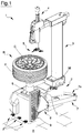
- the tyre changing machine illustrated in the accompanying figures is of the "traditional" type, i.e. provided with a bead breaking arm having a longitudinal direction that is substantially horizontal and provided, at an end thereof, with a paddle-shaped bead breaking tool.
- the present invention is absolutely not limited to said specific "traditional" configuration of a tyre changing machine, and in reality is applicable also to tyre changing machines having different configurations as well as bead breaking assemblies of various types. The description that follows, however, will refer for the sake of simplicity to a tyre changing machine of the "traditional" type, as illustrated in figure 1 .
- the tyre changing machine 1 comprises a support structure or frame 2 restable on a generally horizontal support surface or rest plane A.
- the frame 2 of the tyre changing machine 1 supports an upright or support post 3 having a vertical extension, adapted to support means 4 for mounting/demounting a tyre P to/from a respective rim C of a wheel R.
- the means 4 for mounting/demounting comprise at least a mounting/demounting tool 5, having a lever, hook or the like.
- the mounting/demounting means 4 can further comprise a plurality of accessories, for example a bead presser or the like, not shown in the figures.
- the tyre changing machine 1 illustrated in figure 1 further comprises a wheel support assembly 6, mounted vertically on the frame 2, for locking and rotating a rim of a wheel about a central axis thereof.
- Such assembly 6 can be of various types, for example it can comprise a rotating plate provided with grips for hooking the rim at the annular containing flanges thereof, or, as in the illustrated case in the figures, can be designed to lock the rim at the central hole thereof, using appropriate locking means.
- a bead breaking arm 7 is associated, normally hinged to the frame 2 of the machine 1, about a rotation axis that is substantially vertical, at a first end thereof.
- the associating of the bead breaking arm 7 to the frame can be done directly or indirectly by means of, for example, an intermediate arm 7a, which can be solidly constrained to the frame or associated movably with respect to the frame, for example, but not necessarily, hinged to the frame.
- the bead breaking arm 7 illustrated in figure 1 has a longitudinal extension that is substantially horizontal, though inclined by a few degrees upwards, so as to facilitate the bead breaking operations for wheels having large dimensions.
- bead breaking arms having a longitudinal extension that is substantially horizontal are meant bead breaking arms having a longitudinal horizontal or inclined extension, in general though not necessarily upwards (i.e. on the opposite side with respect to the rest plane of the tyre changing machine), by a few degrees with respect to the horizontal plane, for example inclined by 25° with respect to the horizontal plane, preferably up to 15°. It is however possible, within the scope of the present invention, to have inclinations of the bead breaking arm that are different from those mentioned here purely by way of non-limiting example.
- the bead breaking arm 7 is provided at a second end thereof with a bead breaking tool 8, for example having a blade shape, a paddle shape or another shape.
- the bead breaking tool 8 interacts with the beads of the tyre P to carry out the bead breaking operation, i.e. for detaching said beads from the rim, before the following actual demounting.
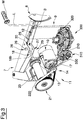
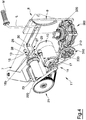
- the bead breaking arm 7 is movable between a disengaged position, in which said bead breaking tool 8, as illustrated in figure 3 , is substantially distanced from the frame 2 and therefore with respect to the tyre of the wheel to be debeaded, and a working position, wherein said bead breaking tool is closer to the frame 2 of the tyre changing machine 1, as illustrated in figure 4 , and therefore can potentially engage on said tyre.
- a substantially vertical opposing surface 9 is mounted on the frame of the bead breaking tool 8 at the area of action of the tyre changing machine, against which opposing surface 9, in use, the wheel R is arranged with the tyre P to be debeaded, also vertically, i.e.
- the opposing surface 9 is adapted to cooperate with the bead breaking tool 8 so as to carry out the bead breaking operation of the tyre P.
- This opposing surface 9, for example made of a plastic material, is knurled so as to increase the coefficient of friction with the wheel R placed against it.
- the tyre changing machine 1 has one or more control pedals F for managing the functions thereof, for example for setting the support assembly 6 in rotation, for locking and/or for freeing the wheel on/from the support assembly 6, so as to activate the bead breaking arm 7, etc.
- the tyre changing machine 1 is provided with a motor device in the form of an electric motor 10, provided with an output drive shaft 10a.
- the electric motor is used for transmitting drive to the support assembly 6, generally for activating at least the rotation.
- the motor device is adapted, as well as setting the support assembly and possibly a rim mounted thereon in rotation, to activate the locking and/or release of the rim on/from the support assembly.
- the bead breaking arm 7 can be provided, in proximity of the bead breaking tool 8, with a control lever L which generally comprises a grip or handle M.
- Said control lever L can advantageously control the electric motor 10 for activating the movement of the bead breaking arm as well as, eventually, for controlling a drive selector device, as illustrated in the following.
- the tyre changing machine 1 of the present invention further includes means 11 for selectively transmitting the drive from the electric motor 10 to the bead breaking arm 7 or to the wheel support assembly 6.
- Said means 11 can be activated by an operator, who can therefore choose, time by time, whether to use the electric motor 10 for activating the wheel support assembly 6 or the bead breaking arm 7.
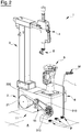
- a lateral casing has been removed from the tyre changing machine 1 in order to make visible the position of the means 11 for selectively transmitting the drive from the electric motor 10, with reference to a preferred embodiment.
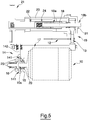
- the electric motor 10 is provided with the drive shaft 10a on which a drive selector device 14 is mounted.
- a first pulley 15 is mounted idle on the drive shaft 10a and is adapted to transmit the drive to the wheel support assembly 6;
- a second pulley 16 is also mounted idle on the drive shaft and is adapted to transmit drive to the bead breaking arm 7.
- both the pulleys are supported on the shaft by appropriate support elements 20, for example bearings, and retained in the seating by retaining means.
- the drive selector device 14 is configured to be removably coupled to the first 15 or the second 16 pulley.
- Said removable coupling is preferably made in the following way.
- the drive selector device 14 comprises a selector element 141 and a control device 142.
- the selector element 141 preferably has a circular crown shape, and is mounted on the drive shaft 10a by a woodruff key coupling, i.e. with the use of grooved profiles. In this way, the selector element 141 cannot move radially with respect to the axis of the drive shaft 10a, however it is free to slide axially thereon.
- the selector element 141 is axially moved by the control device 142, which is preferably fork-shaped, and is coupled to the selector element 141 at a peripheral annular portion thereof.
- the control device 142 is therefore adapted to translate the selector element 141 axially along the drive shaft 10a, in order to enmesh the first or second pulley, according to the direction of the axial translation which is imparted thereon.
- the selector element 141 can be of various types, for example having frontal enmeshing.
- the coupling between the selector element 141 and the pulleys is therefore temporary.
- said selector element 141 can slide axially along the drive shaft 10a in response to a stress received from the fork-shaped control device 142, which in turn is activated by appropriate control means 19 activatable by an operator.
- the control means 19 can be connected to the control lever L associated to the bead breaking arm 7, or can be connected to various control means, for example to a second control lever distinct from the first lever L, or a pedal, a button or the like, also in combination with each other.
- Figure 5 illustrates a case in which the selector element 141 is enmeshed on the first pulley 15. It transmits drive, by means of a first belt 210, to the wheel support assembly 6.
- the first belt 210 is preferably a trapezoidal-profiled belt. With reference to figures 3 and 4 , the belt 210 sets a pulley 310 in rotation. Said pulley 310 is connected to appropriate means 300 for setting the wheel support assembly 6 in rotation.
- the means 300 comprise a shaft 330 set in rotation by the pulley 310 and having a screw-shaped manoeuvring portion, for example an endless screw, which is coupled to a cogwheel and/or to other transmission elements, for example comprising a reducer assembly, adapted to set in rotation the shaft 320 which in turn moves the wheel support assembly 6.
- a screw-shaped manoeuvring portion for example an endless screw
- other transmission elements for example comprising a reducer assembly
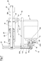
- Figure 6 illustrates the case in which the selector element 141 is enmeshed on the second pulley 16. It transmits drive to the bead breaking arm 7 by means of a second belt 220.
- the second belt 220 is preferably of the Poly-V type or it is a cogged belt, with cogs arranged transversally with respect to the longitudinal extension thereof.
- the second belt 220 engages and sets in rotation a pulley 21 operatively connected to a tubular body 22.
- the rotation of the second pulley 16 then sets in rotation the pulley 21 and therefore also the tubular body 22.
- the means for transmitting drive from the electric motor to the bead breaking arm comprises a pulley 21 mounted solidly to the tubular body 22, which is supported by means of appropriate bearings, for example of a type having conical rollers, by a support tube 23 solidal to the frame 2 of the tyre changing machine.
- the tubular body 22 is internally hollow, and comprises at least a nut screw-shaped portion.
- the nut screw-shaped portion can be made with an endless screw 24 solidly fixed to the tubular body.
- the endless screw 24 is operatively coupled with a screw-shaped manoeuvring portion 18a of a rod element 18.
- the screw-shaped manoeuvring portion 18a is preferably of the trapezoidal screw type, and consequently the endless screw 24 is preferably of the trapezoidal type.
- the rotation of the tubular body 22 and of the endless screw 24 therefore set the rod element 18 in movement, which slides axially, in screwing and/or unscrewing direction, at least partially within the tubular body.
- the rod element 18, while remaining operatively connected to the endless screw 24, will generally be adapted at least partially to exit from the tubular body 22, so as to engage appropriate connecting means 25 associated to the bead breaking arm 7.
- the rod element 18 further comprises a second portion 18b, for example, but not necessarily, having an at least partially circular section, which is preferably smooth, i.e. does not have threads.
- the tube 23 is provided with a flange 31 which interacts with the smooth portion 18b of the rod element 18, thus preventing an eventual rotation thereof and ensuring a movement of a purely translational type.
- the interaction of the flange 31 with the smooth portion 18b of the rod element 18 occurs by virtue of a shoulder (not illustrated in the figures) fashioned on the smooth portion 18b of the rod element 18.
- Said second smooth portion 18b of the rod element 18 is preferably destined to engage in the connecting means 25, which for example comprises a sleeve-shaped element, in which the smooth portion 18b of the rod element 18 can freely slide.
- the sleeve is provided with a first and a second pins 26, 27 destined to engage in respective slots 28, 29 fashioned on the bead breaking arm 7.
- the two pins 26, 27 are preferably arranged along the same vertical axis.
- the two slots 28, 29 are fashioned on respective surfaces solidly constrained to the bead breaking arm, a first surface located in a distal position with respect to the rest plane A, and a second surface located in a proximal position with respect to said rest plane A.
- control means 19 activatable by an operator can comprise a Bowden cable 12 connected to a movable block B, which can also have a cam shape, solidly constrained to the base of the lever L.
- the Bowden cable 12 is pulled, which causes the decoupling of the drive selector device 14 from the first pulley 15 and the coupling thereof with the second pulley 16, so as to transmit drive to the bead breaking arm.
- the movable block B located at the base of the lever L can also be provided with a button device, for example of the microswitch type (not illustrated in the figures) which is activated by the rotation of the block B and which can be configured so as to send a switching-on command to the electric motor 10.
- a button device for example of the microswitch type (not illustrated in the figures) which is activated by the rotation of the block B and which can be configured so as to send a switching-on command to the electric motor 10.
- the electric motor 10 can alternatively be activated by means of a button (not illustrated in the figures), for example located in proximity of the handle M of the lever L.
- the transmission of drive from the first pulley 15 to the wheel support assembly 6 or from the second pulley 16 to the bead breaking arm 7 is lastly realised by use of the first and/or second transmission belts 210, 220.
- the Bowden cable 12 operatively connects the lever L to a control and stop element 13 having a shape of a connecting bracket, which is mounted at a first end of a control rod 17 connected at a second end thereof to the drive selector device 14.
- control and stop element 13 is in turn connected to the means for transmitting drive from the electric motor 10 to the bead breaking arm 7, as illustrated in figure 7 .
- the terminal part of the control and stop element 13 is sleeve-shaped and extends about the rod element 18.
- the control and stop element 13 is configured for automatically assuming, when the bead breaking arm 7 is in the disengaged position i.e. the maximum opening position, a rest position, in which it is ready to be subjected to the pulling action of the Bowden cable, and it is further substantially displaced towards the right, i.e. into the distal position with respect to the tubular body 22, so as to cause the drive selector device 14 to couple with the first pulley 15 and therefore transmit drive only to the wheel support assembly 6.
- control and stop element 13 is configured so as to assume an operating position, in which it is substantially displaced towards the left (for example as illustrated in figure 7 ), so as to cause the drive selector device 14 to couple with the second pulley 16 and therefore transmit the drive only to the bead breaking arm 7.
- control and stop element 13 can be configured so as to act on a control device, for example of the microswitch type, for automatically controlling the switching-off of the motor on conclusion of the translational opening motion of the rod element.
- the microswitch device (not illustrated in the figures) can usefully be mounted solidly to the frame 2 of the tyre changing machine 1.
Landscapes
- Engineering & Computer Science (AREA)
- Mechanical Engineering (AREA)
- Tires In General (AREA)
- Tyre Moulding (AREA)
- Separation, Recovery Or Treatment Of Waste Materials Containing Plastics (AREA)
- Automatic Assembly (AREA)
Claims (15)
- Reifenmontiermaschine (1), umfassend:einen Rahmen (2), der auf einer Auflagefläche (A) aufliegen kann;eine Radträgeranordnung (6) zum Verriegeln und Drehen einer Felge (C) eines Rades (R), von der ein entsprechender Reifen (P) zu demontieren ist oder auf der dieser zu montieren ist, wobei die Radträgeranordnung (6) an dem Rahmen (2) montiert ist;wenigstens einen Abdrückarm (7), der dem Rahmen (2) zugeordnet sein kann;ein Abdrückwerkzeug (8), das dem Abdrückarm (7) zugeordnet ist und geeignet ist, einen Abdrückvorgang des Reifens von dem Rad auszuführen, wobei der Abdrückarm (7) zwischen einer ausgerückten Position, in der das Abdrückwerkzeug (8) in Bezug auf den abzudrückenden Reifen im Wesentlichen beabstandet ist, und einer Arbeitsposition, in der das Abdrückwerkzeug (8) an dem Reifen angreifen kann, bewegbar ist;dadurch gekennzeichnet, dass die Reifenmontiermaschine (1) ferner umfasst:einen Elektromotor (10) mit einer Abtriebswelle (10a) zum Bewegen des Abdrückarms (7) zwischen der ausgerückten Position und der Arbeitsposition und/oder umgekehrt, undMittel (11) zum selektiven Übertragen des Antriebs von dem Elektromotor (10) auf den Abdrückarm (7) oder auf die Radträgeranordnung (6), die geeignet sind, den Abdrückarm (7) oder die Radträgeranordnung (6) selektiv zu aktivieren.
- Reifenmontiermaschine (1) nach Anspruch 1, wobei die Mittel (11) zum selektiven Übertragen des Antriebs von dem Elektromotor (10) auf den Abdrückarm (7) oder auf die Radträgeranordnung (6) umfassen:eine der Abtriebswelle (10a) zugeordnete Antriebsauswahlvorrichtung (14);ein erstes Antriebsübertragungsmittel (15), das auf der Abtriebswelle (10a) montiert ist und geeignet ist, den Antrieb auf die Radträgeranordnung (6) zu übertragen;ein zweites Antriebsübertragungsmittel (16), das auf der Abtriebswelle (10a) montiert ist und geeignet ist, den Antrieb auf den Abdrückarm (7) zu übertragen; und wobeidie Antriebsauswahlvorrichtung (14) geeignet ist, mit dem ersten oder dem zweiten Antriebsübertragungsmittel lösbar gekoppelt zu werden.
- Reifenmontiermaschine nach Anspruch 2, wobeidas erste Antriebsübertragungsmittel eine erste Rolle (15) und entsprechende erste flexible Elemente (210) zur Antriebsübertragung, die der ersten Rolle (15) zugeordnet sind, umfasst; und wobeidas zweite Antriebsübertragungsmittel eine zweite Rolle (16) und entsprechende zweite flexible Elemente (220) zur Antriebsübertragung, die der zweiten Rolle (16) zugeordnet sind, umfasst.
- Reifenmontiermaschine nach Anspruch 2, wobeidas erste Antriebsübertragungsmittel (15) wenigstens ein erstes Zahnrad umfasst; und wobeidas zweite Antriebsübertragungsmittel (16) wenigstens ein zweites Zahnrad umfasst.
- Reifenmontiermaschine nach Anspruch 1 ferner umfassend:eine Radhebevorrichtung, die dem Rahmen (2) zugeordnet sein kann, um das Rad (R) von der Auflagefläche (A) zu der Radträgeranordnung (6) und/oder umgekehrt zu bewegen; und wobeidie Mittel (11) zum selektiven Übertragen des Antriebs von dem Elektromotor (10) geeignet sind, den Abdrückarm (7) oder die Radträgeranordnung (6) oder die Radhebevorrichtung selektiv zu aktivieren.
- Reifenmontiermaschine nach den Ansprüchen 2, 3 oder 4, wobei die Antriebsauswahlvorrichtung (14) umfasstein Wählelement (141), das vorzugsweise eine kreisförmiger Kronenform aufweist und das radial fest und axial beweglich in Bezug auf die Abtriebswelle (10a) auf derselben montiert ist;eine Steuervorrichtung (142), die vorzugsweise eine Gabelform aufweist, um das Wählelement (141) entlang der Abtriebswelle (10a) axial zu verschieben und jeweils mit dem ersten oder dem zweiten Antriebsübertragungsmittel in Eingriff zu gelangen.
- Reifenmontiermaschine nach einem der vorangehenden Ansprüche,wobei die Mittel (11) zum selektiven Übertragen des Antriebs von dem Rahmen (2) gestützt werden und ein Gewindemittel (18) mit einem Außengewinde und ein hohles Gegengewindemittel (24), das mit dem Gewindemittel (18) operativ gekoppelt ist, umfassen;und wobei die Reifenmontiermaschine ferner umfasst:ein Verbindungsmittel (25) zum operativen Zuordnen der Mittel (11) zum selektiven Übertragen des Antriebs auf den Abdrückarm (7);wobei das Verbindungsmittel (25) geeignet ist, mittels einer frei gleitenden Kupplung mit dem Mittel (11) zum selektiven Übertragen des Antriebs auf den Abdrückarm (7) in Eingriff zu gelangen,wobei die Mittel (11) zum selektiven Übertragen des Antriebs ferner ein Schlagelement (30) aufweisen, das geeignet ist, mit dem Verbindungsmittel (25) und/oder dem Abdrückarm (7) in Eingriff zu gelangen.
- Reifenmontiermaschine nach Anspruch 7, wobei das Mittel mit dem Außengewinde ein Stangenelement (18) mit wenigstens einem schraubenförmigen ersten Manövrierabschnitt (18a) aufweist, und wobei das hohle Gegengewindemittel einen rohrförmigen Körper (22) mit einem Durchgangshohlraum aufweist, der wenigstens einen Abschnitt (24) in Mutter-Schraube-Form aufweist, der mit dem schraubenförmigen Manövrierabschnitt (18a) des Stangenelements (18) operativ gekoppelt ist.
- Reifenmontiermaschine nach Anspruch 8, wobei die Mittel (11) zum selektiven Übertragen des Antriebs von dem Elektromotor (10) geeignet sind, den rohrförmigen Körper (22), in dessen Innerem das Stangenelement (18) axial frei gleiten kann, in Festschraub- und/oder Losschraubrichtung in Drehung zu versetzen.
- Reifenmontiermaschine nach den vorangehenden Ansprüchen 8 oder 9, wobei das Verbindungsmittel (25) mit einem zweiten, vorzugsweise glatten Abschnitt (18b) des Stangenelements (18) in Eingriff gelangt.
- Reifenmontiermaschine nach einem der vorangehenden Ansprüche 7 bis 10, wobei das Verbindungsmittel (25) mittels wenigstens eines Stifts (26) an dem Abdrückarm (7) angelenkt ist.
- Reifenmontiermaschine nach Anspruch 11, wobei der wenigstens eine Stift (26) geeignet ist, in einen entsprechenden Schlitz (28) einzugreifen, der in dem Abdrückarm (7) ausgebildet ist.
- Reifenmontiermaschine nach einem der vorangehenden Ansprüche von 7 bis 10, wobei das Verbindungsmittel (25) mittels wenigstens eines ersten Stiftes (26) an einem Zwischenverbindungselement angelenkt ist, und wobei das Zwischenverbindungselement mittels wenigstens eines zweiten Stiftes (27) an dem Abdrückarm (7) angelenkt ist.
- Reifenmontiermaschine nach einem der vorangehenden Ansprüche, wobei das Abdrückwerkzeug (8) schaufelförmig oder scheibenförmig rotierend ist.
- Reifenmontiermaschine nach einem der vorangehenden Ansprüche, die wenigstens zwei Abdrückarme umfasst.
Applications Claiming Priority (3)
| Application Number | Priority Date | Filing Date | Title |
|---|---|---|---|
| ITUB2015A005378A ITUB20155378A1 (it) | 2015-11-10 | 2015-11-10 | Macchina smontagomme |
| ITUB2015A005402A ITUB20155402A1 (it) | 2015-11-10 | 2015-11-10 | Macchina smontagomme |
| PCT/IB2016/052412 WO2017081553A1 (en) | 2015-11-10 | 2016-04-28 | Tyre changing machine |
Publications (2)
| Publication Number | Publication Date |
|---|---|
| EP3374207A1 EP3374207A1 (de) | 2018-09-19 |
| EP3374207B1 true EP3374207B1 (de) | 2020-06-24 |
Family
ID=56117897
Family Applications (2)
| Application Number | Title | Priority Date | Filing Date |
|---|---|---|---|
| EP16728374.6A Active EP3374206B1 (de) | 2015-11-10 | 2016-04-28 | Reifenwechselmaschine |
| EP16729985.8A Active EP3374207B1 (de) | 2015-11-10 | 2016-04-28 | Reifenwechselmaschine |
Family Applications Before (1)
| Application Number | Title | Priority Date | Filing Date |
|---|---|---|---|
| EP16728374.6A Active EP3374206B1 (de) | 2015-11-10 | 2016-04-28 | Reifenwechselmaschine |
Country Status (4)
| Country | Link |
|---|---|
| US (2) | US10828949B2 (de) |
| EP (2) | EP3374206B1 (de) |
| CN (2) | CN108473010B (de) |
| WO (2) | WO2017081554A1 (de) |
Cited By (1)
| Publication number | Priority date | Publication date | Assignee | Title |
|---|---|---|---|---|
| RU239064U1 (ru) * | 2025-07-24 | 2025-11-21 | Инкоу Бойюань Илектроник Текнолоджи Ко., Лтд. | Пневматический шиномонтажный станок |
Families Citing this family (10)
| Publication number | Priority date | Publication date | Assignee | Title |
|---|---|---|---|---|
| IT201800009322A1 (it) * | 2018-10-10 | 2020-04-10 | Butler Eng And Marketing Spa | Macchina di montaggio e/o smontaggio di ruote di veicoli, in particolare ruote da camion |
| CN109455045B (zh) * | 2018-10-23 | 2021-06-08 | 浙江跃岭股份有限公司 | 一种轮胎轮毂的拆卸工装 |
| CN109353167B (zh) * | 2018-11-28 | 2024-02-09 | 安徽省化工设计院 | 一种车轮辅助拆装机器 |
| IT201800020116A1 (it) * | 2018-12-18 | 2020-06-18 | Nexion Spa | Apparato di servizio per la ruota di un veicolo |
| CN111169238A (zh) * | 2020-01-15 | 2020-05-19 | 安徽凤杰金属资源有限公司 | 一种基于立式简易组装的扒胎设备及使用方法 |
| CN112140048B (zh) * | 2020-10-14 | 2021-12-10 | 江苏苏扬包装股份有限公司 | 一种拆卸模具及其使用方法 |
| CN112297724B (zh) * | 2020-11-24 | 2021-08-10 | 中意泰达(营口)汽车保修设备有限公司 | 新型拆装轮胎装置 |
| CN113103832B (zh) * | 2021-04-22 | 2022-02-01 | 南京沃宇机电有限公司 | 一种立式轮胎拆装机器人 |
| IT202200018168A1 (it) * | 2022-09-06 | 2024-03-06 | Nexion Spa | Macchina smontagomme e metodo per utilizzare una macchina smontagomme |
| USD1110380S1 (en) | 2025-01-14 | 2026-01-27 | Haiyu Zhang | Tire changer |
Family Cites Families (33)
| Publication number | Priority date | Publication date | Assignee | Title |
|---|---|---|---|---|
| US3168130A (en) | 1963-08-20 | 1965-02-02 | Eugene W Turpin | Wheel supporting and tire dismounting apparatus |
| US3493030A (en) * | 1967-08-18 | 1970-02-03 | Coats Co Inc The | Tire changing stand with rotatable rim gripping table |
| US3780785A (en) | 1971-09-27 | 1973-12-25 | M Schultz | Bead breaker and tire removal and replacement device |
| FI772081A7 (de) * | 1976-07-07 | 1978-01-08 | Dunlop Ltd | |
| FR2525155B1 (fr) | 1982-04-19 | 1985-07-26 | Wolber | Dispositif de reparation de boyaux et pneumatiques sans chambre |
| IT222810Z2 (it) | 1990-03-23 | 1995-05-08 | Butler Eng & Marketing | Macchina smontagomme |
| US5050659A (en) | 1990-04-27 | 1991-09-24 | G. S. S.R.L. | Machine for the removal and replacement of tires for the wheels of automobiles |
| IT1258032B (it) * | 1992-02-28 | 1996-02-20 | Corghi Spa | Dispositivo stallonatore per macchine smontagomme |
| US5385045A (en) * | 1992-07-15 | 1995-01-31 | Fmc Corporation | Tire changing and balancing machine |
| US5300090A (en) * | 1992-09-03 | 1994-04-05 | Challenge Machinery (Proprietary) Ltd. | Exercise machine |
| RU2088425C1 (ru) | 1993-06-01 | 1997-08-27 | Анатолий Владимирович Молчанов | Шиномонтажная установка |
| IT1262836B (it) * | 1993-09-09 | 1996-07-04 | Giuliano Vignoli | Macchina smontagomme ad azionamento pneumatico. |
| CN2206221Y (zh) * | 1994-09-26 | 1995-08-30 | 吴伟东 | 轮辋轮胎拆装机 |
| CN2332594Y (zh) | 1998-01-12 | 1999-08-11 | 邹呐群 | 一种轮胎拆装机 |
| US6247516B1 (en) * | 2000-04-18 | 2001-06-19 | Rick Sinclair | Tire changing apparatus and method |
| ITMO20020009A1 (it) | 2002-01-17 | 2003-07-17 | Sicam Srl | Gruppo semplificato per l'azionamento del braccio laterale stallonatore per macchine smontagomme |
| CN2767220Y (zh) | 2004-10-29 | 2006-03-29 | 营口新华通发展有限公司 | 轮胎自动拆装机 |
| US7343955B2 (en) | 2005-12-28 | 2008-03-18 | Hennessy Industries, Inc. | Tire changing machine |
| ITMO20060274A1 (it) | 2006-09-08 | 2008-03-09 | Giuliano Spa | Gruppo stallonatore per macchine smontagomme |
| US8613303B1 (en) * | 2008-07-17 | 2013-12-24 | Hunter Engineering Company | Tire changing machine with force detection and control methods |
| US8257226B2 (en) * | 2008-07-14 | 2012-09-04 | Honda Motor Co., Ltd. | Variable speed drivetrain for electronic throttle body |
| IT1394417B1 (it) * | 2009-05-18 | 2012-06-15 | Teco Srl | Utensile per macchine smontagomme |
| IT1396147B1 (it) | 2009-11-05 | 2012-11-16 | Corghi Spa | Apparecchiatura e metodo per il montaggio e lo smontaggio di pneumatici su e da rispettivi cerchioni |
| EP2444260B1 (de) | 2010-10-25 | 2013-03-27 | Snap-on Equipment Srl a unico socio | Synchronisierung von Reifenwulstbrechwerkzeugen |
| IT1403852B1 (it) | 2011-02-08 | 2013-11-08 | Corghi Spa | Apparato e metodo per lo smontaggio di uno pneumatico da un corrispondente cerchione di una ruota. |
| ITMO20110118A1 (it) | 2011-05-20 | 2012-11-21 | Giuliano Group Spa | Gruppo stallonatore per macchine smontagomme |
| CN102963223A (zh) | 2012-11-21 | 2013-03-13 | 英又文 | 一种快捷式手动轮胎拆装装置及其使用方法 |
| ITMO20130110A1 (it) | 2013-04-23 | 2014-10-24 | Giuliano Group Spa | Gruppo stallonatore per macchine smontagomme o simili |
| ITMO20130272A1 (it) | 2013-09-30 | 2015-03-31 | Sicam Srl | Gruppo stallonatore |
| RU2670593C2 (ru) * | 2014-03-14 | 2018-10-23 | СИКАМ С.р.л. | Узел для разбортовки |
| RU2670592C2 (ru) * | 2014-03-25 | 2018-10-23 | СИКАМ С.р.л. | Станок для установки/снятия шин |
| WO2015170273A1 (en) * | 2014-05-07 | 2015-11-12 | Gino Ferrari | A de-beading device for tires changing machines |
| ES2699080T3 (es) * | 2014-09-15 | 2019-02-07 | Nexion Spa | Máquina para ensamblar y retirar un neumático y método para hacer funcionar la máquina |
-
2016
- 2016-04-28 WO PCT/IB2016/052413 patent/WO2017081554A1/en not_active Ceased
- 2016-04-28 US US15/774,955 patent/US10828949B2/en active Active
- 2016-04-28 EP EP16728374.6A patent/EP3374206B1/de active Active
- 2016-04-28 US US15/774,949 patent/US11148482B2/en active Active
- 2016-04-28 EP EP16729985.8A patent/EP3374207B1/de active Active
- 2016-04-28 CN CN201680075040.XA patent/CN108473010B/zh active Active
- 2016-04-28 CN CN201680075051.8A patent/CN108430808B/zh active Active
- 2016-04-28 WO PCT/IB2016/052412 patent/WO2017081553A1/en not_active Ceased
Non-Patent Citations (1)
| Title |
|---|
| None * |
Cited By (1)
| Publication number | Priority date | Publication date | Assignee | Title |
|---|---|---|---|---|
| RU239064U1 (ru) * | 2025-07-24 | 2025-11-21 | Инкоу Бойюань Илектроник Текнолоджи Ко., Лтд. | Пневматический шиномонтажный станок |
Also Published As
| Publication number | Publication date |
|---|---|
| US10828949B2 (en) | 2020-11-10 |
| CN108473010A (zh) | 2018-08-31 |
| US11148482B2 (en) | 2021-10-19 |
| CN108473010B (zh) | 2020-09-04 |
| WO2017081554A1 (en) | 2017-05-18 |
| EP3374206A1 (de) | 2018-09-19 |
| CN108430808A (zh) | 2018-08-21 |
| US20180370302A1 (en) | 2018-12-27 |
| US20180354320A1 (en) | 2018-12-13 |
| EP3374206B1 (de) | 2019-07-17 |
| EP3374207A1 (de) | 2018-09-19 |
| WO2017081553A1 (en) | 2017-05-18 |
| CN108430808B (zh) | 2020-10-16 |
Similar Documents
| Publication | Publication Date | Title |
|---|---|---|
| US10828949B2 (en) | Tyre changing machine | |
| US8646348B2 (en) | Electric push rod and release mechanism combination structure | |
| US20180238426A1 (en) | Release mechanism incorporated linear actuator | |
| US20080203046A1 (en) | Overhead lift storage device | |
| EP2927028B1 (de) | Maschine zur Montage/Demontage eines Reifens | |
| US11148267B2 (en) | Tensioning device for tensioning a helical spring | |
| KR101578371B1 (ko) | 무대장치용 구동부의 비상제동장치 | |
| US20240424550A1 (en) | Hand-held pulling and compression device | |
| CN218907053U (zh) | 预紧力可控的棘轮式张紧器 | |
| CN108908693B (zh) | 一种钢筋预应力张拉机 | |
| EP1262690A2 (de) | Mechanische Vorrichtung zur Umwandlung eines stufenlosen Getriebes in ein sequentielles Getriebe in einem Fahrzeug | |
| US20080105859A1 (en) | Apparatus for the Axial Movement of Piping or the Like | |
| US20040035203A1 (en) | Method and apparatus for centeredly clamping a motor vehicle wheel on a main shaft of a wheel balancing machine | |
| US4355675A (en) | Device for removing a tire from its rim | |
| CN110937531B (zh) | 一种手自一体化吊装驱动机构 | |
| CN105883527A (zh) | 具有速度监控的棘爪自复位单制动压板双向限速器 | |
| CN223279084U (zh) | 一种车辆止退器安全快速放置装置 | |
| CN106541066A (zh) | 用于从铆接设备移除盲铆钉元件的方法 | |
| RU2344917C1 (ru) | Гайковерт | |
| CN223825480U (zh) | 宽带链条换向抽油机双刹车装置及应用其的刹车系统 | |
| CN220311959U (zh) | 一种金属圆锯机机构 | |
| CN216714915U (zh) | 一种手摇式上下棘轮及其伸缩器 | |
| CN218579473U (zh) | 一种门座起重机回转自动锚定装置 | |
| CN110479940B (zh) | 一种液压件铆接机 | |
| SU1110660A1 (ru) | Устройство дл складывани и раскладывани сборочного барабана |
Legal Events
| Date | Code | Title | Description |
|---|---|---|---|
| STAA | Information on the status of an ep patent application or granted ep patent |
Free format text: STATUS: THE INTERNATIONAL PUBLICATION HAS BEEN MADE |
|
| PUAI | Public reference made under article 153(3) epc to a published international application that has entered the european phase |
Free format text: ORIGINAL CODE: 0009012 |
|
| STAA | Information on the status of an ep patent application or granted ep patent |
Free format text: STATUS: REQUEST FOR EXAMINATION WAS MADE |
|
| 17P | Request for examination filed |
Effective date: 20180530 |
|
| AK | Designated contracting states |
Kind code of ref document: A1 Designated state(s): AL AT BE BG CH CY CZ DE DK EE ES FI FR GB GR HR HU IE IS IT LI LT LU LV MC MK MT NL NO PL PT RO RS SE SI SK SM TR |
|
| AX | Request for extension of the european patent |
Extension state: BA ME |
|
| DAV | Request for validation of the european patent (deleted) | ||
| DAX | Request for extension of the european patent (deleted) | ||
| GRAP | Despatch of communication of intention to grant a patent |
Free format text: ORIGINAL CODE: EPIDOSNIGR1 |
|
| STAA | Information on the status of an ep patent application or granted ep patent |
Free format text: STATUS: GRANT OF PATENT IS INTENDED |
|
| INTG | Intention to grant announced |
Effective date: 20191217 |
|
| GRAJ | Information related to disapproval of communication of intention to grant by the applicant or resumption of examination proceedings by the epo deleted |
Free format text: ORIGINAL CODE: EPIDOSDIGR1 |
|
| STAA | Information on the status of an ep patent application or granted ep patent |
Free format text: STATUS: REQUEST FOR EXAMINATION WAS MADE |
|
| INTC | Intention to grant announced (deleted) | ||
| GRAP | Despatch of communication of intention to grant a patent |
Free format text: ORIGINAL CODE: EPIDOSNIGR1 |
|
| GRAJ | Information related to disapproval of communication of intention to grant by the applicant or resumption of examination proceedings by the epo deleted |
Free format text: ORIGINAL CODE: EPIDOSDIGR1 |
|
| GRAR | Information related to intention to grant a patent recorded |
Free format text: ORIGINAL CODE: EPIDOSNIGR71 |
|
| GRAS | Grant fee paid |
Free format text: ORIGINAL CODE: EPIDOSNIGR3 |
|
| STAA | Information on the status of an ep patent application or granted ep patent |
Free format text: STATUS: GRANT OF PATENT IS INTENDED |
|
| GRAJ | Information related to disapproval of communication of intention to grant by the applicant or resumption of examination proceedings by the epo deleted |
Free format text: ORIGINAL CODE: EPIDOSDIGR1 |
|
| GRAR | Information related to intention to grant a patent recorded |
Free format text: ORIGINAL CODE: EPIDOSNIGR71 |
|
| GRAS | Grant fee paid |
Free format text: ORIGINAL CODE: EPIDOSNIGR3 |
|
| GRAJ | Information related to disapproval of communication of intention to grant by the applicant or resumption of examination proceedings by the epo deleted |
Free format text: ORIGINAL CODE: EPIDOSDIGR1 |
|
| GRAR | Information related to intention to grant a patent recorded |
Free format text: ORIGINAL CODE: EPIDOSNIGR71 |
|
| GRAS | Grant fee paid |
Free format text: ORIGINAL CODE: EPIDOSNIGR3 |
|
| GRAA | (expected) grant |
Free format text: ORIGINAL CODE: 0009210 |
|
| STAA | Information on the status of an ep patent application or granted ep patent |
Free format text: STATUS: THE PATENT HAS BEEN GRANTED |
|
| INTG | Intention to grant announced |
Effective date: 20200514 |
|
| AK | Designated contracting states |
Kind code of ref document: B1 Designated state(s): AL AT BE BG CH CY CZ DE DK EE ES FI FR GB GR HR HU IE IS IT LI LT LU LV MC MK MT NL NO PL PT RO RS SE SI SK SM TR |
|
| INTG | Intention to grant announced |
Effective date: 20200518 |
|
| REG | Reference to a national code |
Ref country code: GB Ref legal event code: FG4D |
|
| REG | Reference to a national code |
Ref country code: CH Ref legal event code: EP |
|
| REG | Reference to a national code |
Ref country code: AT Ref legal event code: REF Ref document number: 1283529 Country of ref document: AT Kind code of ref document: T Effective date: 20200715 |
|
| REG | Reference to a national code |
Ref country code: DE Ref legal event code: R096 Ref document number: 602016038703 Country of ref document: DE |
|
| REG | Reference to a national code |
Ref country code: IE Ref legal event code: FG4D |
|
| PG25 | Lapsed in a contracting state [announced via postgrant information from national office to epo] |
Ref country code: LT Free format text: LAPSE BECAUSE OF FAILURE TO SUBMIT A TRANSLATION OF THE DESCRIPTION OR TO PAY THE FEE WITHIN THE PRESCRIBED TIME-LIMIT Effective date: 20200624 Ref country code: FI Free format text: LAPSE BECAUSE OF FAILURE TO SUBMIT A TRANSLATION OF THE DESCRIPTION OR TO PAY THE FEE WITHIN THE PRESCRIBED TIME-LIMIT Effective date: 20200624 Ref country code: SE Free format text: LAPSE BECAUSE OF FAILURE TO SUBMIT A TRANSLATION OF THE DESCRIPTION OR TO PAY THE FEE WITHIN THE PRESCRIBED TIME-LIMIT Effective date: 20200624 Ref country code: NO Free format text: LAPSE BECAUSE OF FAILURE TO SUBMIT A TRANSLATION OF THE DESCRIPTION OR TO PAY THE FEE WITHIN THE PRESCRIBED TIME-LIMIT Effective date: 20200924 Ref country code: GR Free format text: LAPSE BECAUSE OF FAILURE TO SUBMIT A TRANSLATION OF THE DESCRIPTION OR TO PAY THE FEE WITHIN THE PRESCRIBED TIME-LIMIT Effective date: 20200925 |
|
| REG | Reference to a national code |
Ref country code: LT Ref legal event code: MG4D |
|
| PG25 | Lapsed in a contracting state [announced via postgrant information from national office to epo] |
Ref country code: BG Free format text: LAPSE BECAUSE OF FAILURE TO SUBMIT A TRANSLATION OF THE DESCRIPTION OR TO PAY THE FEE WITHIN THE PRESCRIBED TIME-LIMIT Effective date: 20200924 Ref country code: RS Free format text: LAPSE BECAUSE OF FAILURE TO SUBMIT A TRANSLATION OF THE DESCRIPTION OR TO PAY THE FEE WITHIN THE PRESCRIBED TIME-LIMIT Effective date: 20200624 Ref country code: LV Free format text: LAPSE BECAUSE OF FAILURE TO SUBMIT A TRANSLATION OF THE DESCRIPTION OR TO PAY THE FEE WITHIN THE PRESCRIBED TIME-LIMIT Effective date: 20200624 Ref country code: HR Free format text: LAPSE BECAUSE OF FAILURE TO SUBMIT A TRANSLATION OF THE DESCRIPTION OR TO PAY THE FEE WITHIN THE PRESCRIBED TIME-LIMIT Effective date: 20200624 |
|
| REG | Reference to a national code |
Ref country code: NL Ref legal event code: MP Effective date: 20200624 |
|
| REG | Reference to a national code |
Ref country code: AT Ref legal event code: MK05 Ref document number: 1283529 Country of ref document: AT Kind code of ref document: T Effective date: 20200624 |
|
| PG25 | Lapsed in a contracting state [announced via postgrant information from national office to epo] |
Ref country code: AL Free format text: LAPSE BECAUSE OF FAILURE TO SUBMIT A TRANSLATION OF THE DESCRIPTION OR TO PAY THE FEE WITHIN THE PRESCRIBED TIME-LIMIT Effective date: 20200624 Ref country code: NL Free format text: LAPSE BECAUSE OF FAILURE TO SUBMIT A TRANSLATION OF THE DESCRIPTION OR TO PAY THE FEE WITHIN THE PRESCRIBED TIME-LIMIT Effective date: 20200624 |
|
| PG25 | Lapsed in a contracting state [announced via postgrant information from national office to epo] |
Ref country code: EE Free format text: LAPSE BECAUSE OF FAILURE TO SUBMIT A TRANSLATION OF THE DESCRIPTION OR TO PAY THE FEE WITHIN THE PRESCRIBED TIME-LIMIT Effective date: 20200624 Ref country code: SM Free format text: LAPSE BECAUSE OF FAILURE TO SUBMIT A TRANSLATION OF THE DESCRIPTION OR TO PAY THE FEE WITHIN THE PRESCRIBED TIME-LIMIT Effective date: 20200624 Ref country code: RO Free format text: LAPSE BECAUSE OF FAILURE TO SUBMIT A TRANSLATION OF THE DESCRIPTION OR TO PAY THE FEE WITHIN THE PRESCRIBED TIME-LIMIT Effective date: 20200624 Ref country code: AT Free format text: LAPSE BECAUSE OF FAILURE TO SUBMIT A TRANSLATION OF THE DESCRIPTION OR TO PAY THE FEE WITHIN THE PRESCRIBED TIME-LIMIT Effective date: 20200624 Ref country code: CZ Free format text: LAPSE BECAUSE OF FAILURE TO SUBMIT A TRANSLATION OF THE DESCRIPTION OR TO PAY THE FEE WITHIN THE PRESCRIBED TIME-LIMIT Effective date: 20200624 Ref country code: ES Free format text: LAPSE BECAUSE OF FAILURE TO SUBMIT A TRANSLATION OF THE DESCRIPTION OR TO PAY THE FEE WITHIN THE PRESCRIBED TIME-LIMIT Effective date: 20200624 Ref country code: PT Free format text: LAPSE BECAUSE OF FAILURE TO SUBMIT A TRANSLATION OF THE DESCRIPTION OR TO PAY THE FEE WITHIN THE PRESCRIBED TIME-LIMIT Effective date: 20201026 |
|
| PG25 | Lapsed in a contracting state [announced via postgrant information from national office to epo] |
Ref country code: PL Free format text: LAPSE BECAUSE OF FAILURE TO SUBMIT A TRANSLATION OF THE DESCRIPTION OR TO PAY THE FEE WITHIN THE PRESCRIBED TIME-LIMIT Effective date: 20200624 Ref country code: SK Free format text: LAPSE BECAUSE OF FAILURE TO SUBMIT A TRANSLATION OF THE DESCRIPTION OR TO PAY THE FEE WITHIN THE PRESCRIBED TIME-LIMIT Effective date: 20200624 Ref country code: IS Free format text: LAPSE BECAUSE OF FAILURE TO SUBMIT A TRANSLATION OF THE DESCRIPTION OR TO PAY THE FEE WITHIN THE PRESCRIBED TIME-LIMIT Effective date: 20201024 |
|
| REG | Reference to a national code |
Ref country code: DE Ref legal event code: R097 Ref document number: 602016038703 Country of ref document: DE |
|
| PG25 | Lapsed in a contracting state [announced via postgrant information from national office to epo] |
Ref country code: DK Free format text: LAPSE BECAUSE OF FAILURE TO SUBMIT A TRANSLATION OF THE DESCRIPTION OR TO PAY THE FEE WITHIN THE PRESCRIBED TIME-LIMIT Effective date: 20200624 |
|
| PLBE | No opposition filed within time limit |
Free format text: ORIGINAL CODE: 0009261 |
|
| STAA | Information on the status of an ep patent application or granted ep patent |
Free format text: STATUS: NO OPPOSITION FILED WITHIN TIME LIMIT |
|
| 26N | No opposition filed |
Effective date: 20210325 |
|
| PG25 | Lapsed in a contracting state [announced via postgrant information from national office to epo] |
Ref country code: SI Free format text: LAPSE BECAUSE OF FAILURE TO SUBMIT A TRANSLATION OF THE DESCRIPTION OR TO PAY THE FEE WITHIN THE PRESCRIBED TIME-LIMIT Effective date: 20200624 |
|
| PG25 | Lapsed in a contracting state [announced via postgrant information from national office to epo] |
Ref country code: MC Free format text: LAPSE BECAUSE OF FAILURE TO SUBMIT A TRANSLATION OF THE DESCRIPTION OR TO PAY THE FEE WITHIN THE PRESCRIBED TIME-LIMIT Effective date: 20200624 |
|
| GBPC | Gb: european patent ceased through non-payment of renewal fee |
Effective date: 20210428 |
|
| PG25 | Lapsed in a contracting state [announced via postgrant information from national office to epo] |
Ref country code: LU Free format text: LAPSE BECAUSE OF NON-PAYMENT OF DUE FEES Effective date: 20210428 |
|
| REG | Reference to a national code |
Ref country code: BE Ref legal event code: MM Effective date: 20210430 |
|
| PG25 | Lapsed in a contracting state [announced via postgrant information from national office to epo] |
Ref country code: CH Free format text: LAPSE BECAUSE OF NON-PAYMENT OF DUE FEES Effective date: 20210430 Ref country code: LI Free format text: LAPSE BECAUSE OF NON-PAYMENT OF DUE FEES Effective date: 20210430 Ref country code: GB Free format text: LAPSE BECAUSE OF NON-PAYMENT OF DUE FEES Effective date: 20210428 |
|
| PG25 | Lapsed in a contracting state [announced via postgrant information from national office to epo] |
Ref country code: IE Free format text: LAPSE BECAUSE OF NON-PAYMENT OF DUE FEES Effective date: 20210428 |
|
| PG25 | Lapsed in a contracting state [announced via postgrant information from national office to epo] |
Ref country code: IS Free format text: LAPSE BECAUSE OF FAILURE TO SUBMIT A TRANSLATION OF THE DESCRIPTION OR TO PAY THE FEE WITHIN THE PRESCRIBED TIME-LIMIT Effective date: 20201024 |
|
| PG25 | Lapsed in a contracting state [announced via postgrant information from national office to epo] |
Ref country code: BE Free format text: LAPSE BECAUSE OF NON-PAYMENT OF DUE FEES Effective date: 20210430 |
|
| P01 | Opt-out of the competence of the unified patent court (upc) registered |
Effective date: 20230517 |
|
| PG25 | Lapsed in a contracting state [announced via postgrant information from national office to epo] |
Ref country code: CY Free format text: LAPSE BECAUSE OF FAILURE TO SUBMIT A TRANSLATION OF THE DESCRIPTION OR TO PAY THE FEE WITHIN THE PRESCRIBED TIME-LIMIT Effective date: 20200624 |
|
| PG25 | Lapsed in a contracting state [announced via postgrant information from national office to epo] |
Ref country code: HU Free format text: LAPSE BECAUSE OF FAILURE TO SUBMIT A TRANSLATION OF THE DESCRIPTION OR TO PAY THE FEE WITHIN THE PRESCRIBED TIME-LIMIT; INVALID AB INITIO Effective date: 20160428 |
|
| PG25 | Lapsed in a contracting state [announced via postgrant information from national office to epo] |
Ref country code: MK Free format text: LAPSE BECAUSE OF FAILURE TO SUBMIT A TRANSLATION OF THE DESCRIPTION OR TO PAY THE FEE WITHIN THE PRESCRIBED TIME-LIMIT Effective date: 20200624 |
|
| PG25 | Lapsed in a contracting state [announced via postgrant information from national office to epo] |
Ref country code: MT Free format text: LAPSE BECAUSE OF FAILURE TO SUBMIT A TRANSLATION OF THE DESCRIPTION OR TO PAY THE FEE WITHIN THE PRESCRIBED TIME-LIMIT Effective date: 20200624 |
|
| PGFP | Annual fee paid to national office [announced via postgrant information from national office to epo] |
Ref country code: DE Payment date: 20250429 Year of fee payment: 10 |
|
| PGFP | Annual fee paid to national office [announced via postgrant information from national office to epo] |
Ref country code: IT Payment date: 20250422 Year of fee payment: 10 |
|
| PGFP | Annual fee paid to national office [announced via postgrant information from national office to epo] |
Ref country code: FR Payment date: 20250425 Year of fee payment: 10 |
|
| PG25 | Lapsed in a contracting state [announced via postgrant information from national office to epo] |
Ref country code: TR Free format text: LAPSE BECAUSE OF FAILURE TO SUBMIT A TRANSLATION OF THE DESCRIPTION OR TO PAY THE FEE WITHIN THE PRESCRIBED TIME-LIMIT Effective date: 20200624 |