EP3373329B1 - Integrated circuit comprising a laterally diffused mos field effect transistor - Google Patents
Integrated circuit comprising a laterally diffused mos field effect transistor Download PDFInfo
- Publication number
- EP3373329B1 EP3373329B1 EP18159759.2A EP18159759A EP3373329B1 EP 3373329 B1 EP3373329 B1 EP 3373329B1 EP 18159759 A EP18159759 A EP 18159759A EP 3373329 B1 EP3373329 B1 EP 3373329B1
- Authority
- EP
- European Patent Office
- Prior art keywords
- wafer
- backside
- substrate
- frontside
- transistor
- Prior art date
- Legal status (The legal status is an assumption and is not a legal conclusion. Google has not performed a legal analysis and makes no representation as to the accuracy of the status listed.)
- Active
Links
- 230000005669 field effect Effects 0.000 title description 3
- 239000000758 substrate Substances 0.000 claims description 59
- 239000004065 semiconductor Substances 0.000 claims description 45
- 230000004888 barrier function Effects 0.000 claims description 7
- 239000011810 insulating material Substances 0.000 claims description 3
- 235000012431 wafers Nutrition 0.000 description 220
- 229910052751 metal Inorganic materials 0.000 description 57
- 239000002184 metal Substances 0.000 description 57
- XUIMIQQOPSSXEZ-UHFFFAOYSA-N Silicon Chemical compound [Si] XUIMIQQOPSSXEZ-UHFFFAOYSA-N 0.000 description 54
- 229910052710 silicon Inorganic materials 0.000 description 53
- 239000010703 silicon Substances 0.000 description 53
- 238000000034 method Methods 0.000 description 52
- 230000008569 process Effects 0.000 description 39
- 238000002955 isolation Methods 0.000 description 38
- VYPSYNLAJGMNEJ-UHFFFAOYSA-N Silicium dioxide Chemical compound O=[Si]=O VYPSYNLAJGMNEJ-UHFFFAOYSA-N 0.000 description 36
- 238000002513 implantation Methods 0.000 description 24
- 239000000377 silicon dioxide Substances 0.000 description 18
- 235000012239 silicon dioxide Nutrition 0.000 description 18
- 238000004519 manufacturing process Methods 0.000 description 15
- 239000002019 doping agent Substances 0.000 description 11
- 238000000151 deposition Methods 0.000 description 10
- 238000011049 filling Methods 0.000 description 10
- 241000724291 Tobacco streak virus Species 0.000 description 9
- 238000005530 etching Methods 0.000 description 9
- 238000000137 annealing Methods 0.000 description 8
- 230000008021 deposition Effects 0.000 description 8
- 239000003989 dielectric material Substances 0.000 description 8
- 239000000463 material Substances 0.000 description 8
- 238000001465 metallisation Methods 0.000 description 8
- 230000015556 catabolic process Effects 0.000 description 7
- 238000002161 passivation Methods 0.000 description 7
- UMIVXZPTRXBADB-UHFFFAOYSA-N benzocyclobutene Chemical compound C1=CC=C2CCC2=C1 UMIVXZPTRXBADB-UHFFFAOYSA-N 0.000 description 6
- 230000003071 parasitic effect Effects 0.000 description 6
- BOTDANWDWHJENH-UHFFFAOYSA-N Tetraethyl orthosilicate Chemical compound CCO[Si](OCC)(OCC)OCC BOTDANWDWHJENH-UHFFFAOYSA-N 0.000 description 5
- 230000015572 biosynthetic process Effects 0.000 description 5
- 229910052782 aluminium Inorganic materials 0.000 description 4
- XAGFODPZIPBFFR-UHFFFAOYSA-N aluminium Chemical compound [Al] XAGFODPZIPBFFR-UHFFFAOYSA-N 0.000 description 4
- 239000004020 conductor Substances 0.000 description 4
- 238000010586 diagram Methods 0.000 description 4
- 238000000623 plasma-assisted chemical vapour deposition Methods 0.000 description 4
- 238000005498 polishing Methods 0.000 description 4
- RYGMFSIKBFXOCR-UHFFFAOYSA-N Copper Chemical compound [Cu] RYGMFSIKBFXOCR-UHFFFAOYSA-N 0.000 description 3
- CBENFWSGALASAD-UHFFFAOYSA-N Ozone Chemical compound [O-][O+]=O CBENFWSGALASAD-UHFFFAOYSA-N 0.000 description 3
- 229910052802 copper Inorganic materials 0.000 description 3
- 239000010949 copper Substances 0.000 description 3
- 230000005684 electric field Effects 0.000 description 3
- 239000007943 implant Substances 0.000 description 3
- 238000001020 plasma etching Methods 0.000 description 3
- 239000002210 silicon-based material Substances 0.000 description 3
- 229910052581 Si3N4 Inorganic materials 0.000 description 2
- 210000000746 body region Anatomy 0.000 description 2
- 238000001312 dry etching Methods 0.000 description 2
- 238000000227 grinding Methods 0.000 description 2
- 230000017525 heat dissipation Effects 0.000 description 2
- 239000012212 insulator Substances 0.000 description 2
- 230000010354 integration Effects 0.000 description 2
- 229910021420 polycrystalline silicon Inorganic materials 0.000 description 2
- 229920005591 polysilicon Polymers 0.000 description 2
- HQVNEWCFYHHQES-UHFFFAOYSA-N silicon nitride Chemical compound N12[Si]34N5[Si]62N3[Si]51N64 HQVNEWCFYHHQES-UHFFFAOYSA-N 0.000 description 2
- 239000000126 substance Substances 0.000 description 2
- WFKWXMTUELFFGS-UHFFFAOYSA-N tungsten Chemical compound [W] WFKWXMTUELFFGS-UHFFFAOYSA-N 0.000 description 2
- 229910052721 tungsten Inorganic materials 0.000 description 2
- 239000010937 tungsten Substances 0.000 description 2
- VMXJCRHCUWKQCB-UHFFFAOYSA-N NPNP Chemical group NPNP VMXJCRHCUWKQCB-UHFFFAOYSA-N 0.000 description 1
- ATJFFYVFTNAWJD-UHFFFAOYSA-N Tin Chemical compound [Sn] ATJFFYVFTNAWJD-UHFFFAOYSA-N 0.000 description 1
- 238000005411 Van der Waals force Methods 0.000 description 1
- 230000009471 action Effects 0.000 description 1
- 230000004913 activation Effects 0.000 description 1
- 239000000853 adhesive Substances 0.000 description 1
- 238000004026 adhesive bonding Methods 0.000 description 1
- 230000001070 adhesive effect Effects 0.000 description 1
- 230000002411 adverse Effects 0.000 description 1
- 238000003486 chemical etching Methods 0.000 description 1
- 239000002131 composite material Substances 0.000 description 1
- 230000007547 defect Effects 0.000 description 1
- 239000011521 glass Substances 0.000 description 1
- 239000011261 inert gas Substances 0.000 description 1
- 238000009413 insulation Methods 0.000 description 1
- 150000002500 ions Chemical class 0.000 description 1
- 238000013532 laser treatment Methods 0.000 description 1
- 230000000873 masking effect Effects 0.000 description 1
- 150000002739 metals Chemical group 0.000 description 1
- 239000000203 mixture Substances 0.000 description 1
- 238000005457 optimization Methods 0.000 description 1
- 238000004806 packaging method and process Methods 0.000 description 1
- 238000007517 polishing process Methods 0.000 description 1
- 229920000642 polymer Polymers 0.000 description 1
- 230000004044 response Effects 0.000 description 1
- 238000001039 wet etching Methods 0.000 description 1
Images


Classifications
-
- H—ELECTRICITY
- H01—ELECTRIC ELEMENTS
- H01L—SEMICONDUCTOR DEVICES NOT COVERED BY CLASS H10
- H01L21/00—Processes or apparatus adapted for the manufacture or treatment of semiconductor or solid state devices or of parts thereof
- H01L21/67—Apparatus specially adapted for handling semiconductor or electric solid state devices during manufacture or treatment thereof; Apparatus specially adapted for handling wafers during manufacture or treatment of semiconductor or electric solid state devices or components ; Apparatus not specifically provided for elsewhere
- H01L21/683—Apparatus specially adapted for handling semiconductor or electric solid state devices during manufacture or treatment thereof; Apparatus specially adapted for handling wafers during manufacture or treatment of semiconductor or electric solid state devices or components ; Apparatus not specifically provided for elsewhere for supporting or gripping
- H01L21/6835—Apparatus specially adapted for handling semiconductor or electric solid state devices during manufacture or treatment thereof; Apparatus specially adapted for handling wafers during manufacture or treatment of semiconductor or electric solid state devices or components ; Apparatus not specifically provided for elsewhere for supporting or gripping using temporarily an auxiliary support
-
- H—ELECTRICITY
- H01—ELECTRIC ELEMENTS
- H01L—SEMICONDUCTOR DEVICES NOT COVERED BY CLASS H10
- H01L23/00—Details of semiconductor or other solid state devices
- H01L23/562—Protection against mechanical damage
-
- H—ELECTRICITY
- H01—ELECTRIC ELEMENTS
- H01L—SEMICONDUCTOR DEVICES NOT COVERED BY CLASS H10
- H01L21/00—Processes or apparatus adapted for the manufacture or treatment of semiconductor or solid state devices or of parts thereof
- H01L21/70—Manufacture or treatment of devices consisting of a plurality of solid state components formed in or on a common substrate or of parts thereof; Manufacture of integrated circuit devices or of parts thereof
- H01L21/71—Manufacture of specific parts of devices defined in group H01L21/70
- H01L21/74—Making of localized buried regions, e.g. buried collector layers, internal connections substrate contacts
- H01L21/743—Making of internal connections, substrate contacts
-
- H—ELECTRICITY
- H01—ELECTRIC ELEMENTS
- H01L—SEMICONDUCTOR DEVICES NOT COVERED BY CLASS H10
- H01L21/00—Processes or apparatus adapted for the manufacture or treatment of semiconductor or solid state devices or of parts thereof
- H01L21/70—Manufacture or treatment of devices consisting of a plurality of solid state components formed in or on a common substrate or of parts thereof; Manufacture of integrated circuit devices or of parts thereof
- H01L21/71—Manufacture of specific parts of devices defined in group H01L21/70
- H01L21/76—Making of isolation regions between components
- H01L21/762—Dielectric regions, e.g. EPIC dielectric isolation, LOCOS; Trench refilling techniques, SOI technology, use of channel stoppers
- H01L21/76224—Dielectric regions, e.g. EPIC dielectric isolation, LOCOS; Trench refilling techniques, SOI technology, use of channel stoppers using trench refilling with dielectric materials
-
- H—ELECTRICITY
- H01—ELECTRIC ELEMENTS
- H01L—SEMICONDUCTOR DEVICES NOT COVERED BY CLASS H10
- H01L21/00—Processes or apparatus adapted for the manufacture or treatment of semiconductor or solid state devices or of parts thereof
- H01L21/70—Manufacture or treatment of devices consisting of a plurality of solid state components formed in or on a common substrate or of parts thereof; Manufacture of integrated circuit devices or of parts thereof
- H01L21/71—Manufacture of specific parts of devices defined in group H01L21/70
- H01L21/768—Applying interconnections to be used for carrying current between separate components within a device comprising conductors and dielectrics
- H01L21/76898—Applying interconnections to be used for carrying current between separate components within a device comprising conductors and dielectrics formed through a semiconductor substrate
-
- H—ELECTRICITY
- H01—ELECTRIC ELEMENTS
- H01L—SEMICONDUCTOR DEVICES NOT COVERED BY CLASS H10
- H01L23/00—Details of semiconductor or other solid state devices
- H01L23/52—Arrangements for conducting electric current within the device in operation from one component to another, i.e. interconnections, e.g. wires, lead frames
- H01L23/522—Arrangements for conducting electric current within the device in operation from one component to another, i.e. interconnections, e.g. wires, lead frames including external interconnections consisting of a multilayer structure of conductive and insulating layers inseparably formed on the semiconductor body
- H01L23/5226—Via connections in a multilevel interconnection structure
-
- H—ELECTRICITY
- H01—ELECTRIC ELEMENTS
- H01L—SEMICONDUCTOR DEVICES NOT COVERED BY CLASS H10
- H01L23/00—Details of semiconductor or other solid state devices
- H01L23/52—Arrangements for conducting electric current within the device in operation from one component to another, i.e. interconnections, e.g. wires, lead frames
- H01L23/522—Arrangements for conducting electric current within the device in operation from one component to another, i.e. interconnections, e.g. wires, lead frames including external interconnections consisting of a multilayer structure of conductive and insulating layers inseparably formed on the semiconductor body
- H01L23/528—Geometry or layout of the interconnection structure
-
- H—ELECTRICITY
- H01—ELECTRIC ELEMENTS
- H01L—SEMICONDUCTOR DEVICES NOT COVERED BY CLASS H10
- H01L24/00—Arrangements for connecting or disconnecting semiconductor or solid-state bodies; Methods or apparatus related thereto
- H01L24/01—Means for bonding being attached to, or being formed on, the surface to be connected, e.g. chip-to-package, die-attach, "first-level" interconnects; Manufacturing methods related thereto
- H01L24/42—Wire connectors; Manufacturing methods related thereto
- H01L24/43—Manufacturing methods
-
- H—ELECTRICITY
- H01—ELECTRIC ELEMENTS
- H01L—SEMICONDUCTOR DEVICES NOT COVERED BY CLASS H10
- H01L27/00—Devices consisting of a plurality of semiconductor or other solid-state components formed in or on a common substrate
- H01L27/02—Devices consisting of a plurality of semiconductor or other solid-state components formed in or on a common substrate including semiconductor components specially adapted for rectifying, oscillating, amplifying or switching and having at least one potential-jump barrier or surface barrier; including integrated passive circuit elements with at least one potential-jump barrier or surface barrier
- H01L27/04—Devices consisting of a plurality of semiconductor or other solid-state components formed in or on a common substrate including semiconductor components specially adapted for rectifying, oscillating, amplifying or switching and having at least one potential-jump barrier or surface barrier; including integrated passive circuit elements with at least one potential-jump barrier or surface barrier the substrate being a semiconductor body
- H01L27/06—Devices consisting of a plurality of semiconductor or other solid-state components formed in or on a common substrate including semiconductor components specially adapted for rectifying, oscillating, amplifying or switching and having at least one potential-jump barrier or surface barrier; including integrated passive circuit elements with at least one potential-jump barrier or surface barrier the substrate being a semiconductor body including a plurality of individual components in a non-repetitive configuration
- H01L27/0611—Devices consisting of a plurality of semiconductor or other solid-state components formed in or on a common substrate including semiconductor components specially adapted for rectifying, oscillating, amplifying or switching and having at least one potential-jump barrier or surface barrier; including integrated passive circuit elements with at least one potential-jump barrier or surface barrier the substrate being a semiconductor body including a plurality of individual components in a non-repetitive configuration integrated circuits having a two-dimensional layout of components without a common active region
-
- H—ELECTRICITY
- H01—ELECTRIC ELEMENTS
- H01L—SEMICONDUCTOR DEVICES NOT COVERED BY CLASS H10
- H01L27/00—Devices consisting of a plurality of semiconductor or other solid-state components formed in or on a common substrate
- H01L27/02—Devices consisting of a plurality of semiconductor or other solid-state components formed in or on a common substrate including semiconductor components specially adapted for rectifying, oscillating, amplifying or switching and having at least one potential-jump barrier or surface barrier; including integrated passive circuit elements with at least one potential-jump barrier or surface barrier
- H01L27/04—Devices consisting of a plurality of semiconductor or other solid-state components formed in or on a common substrate including semiconductor components specially adapted for rectifying, oscillating, amplifying or switching and having at least one potential-jump barrier or surface barrier; including integrated passive circuit elements with at least one potential-jump barrier or surface barrier the substrate being a semiconductor body
- H01L27/08—Devices consisting of a plurality of semiconductor or other solid-state components formed in or on a common substrate including semiconductor components specially adapted for rectifying, oscillating, amplifying or switching and having at least one potential-jump barrier or surface barrier; including integrated passive circuit elements with at least one potential-jump barrier or surface barrier the substrate being a semiconductor body including only semiconductor components of a single kind
- H01L27/085—Devices consisting of a plurality of semiconductor or other solid-state components formed in or on a common substrate including semiconductor components specially adapted for rectifying, oscillating, amplifying or switching and having at least one potential-jump barrier or surface barrier; including integrated passive circuit elements with at least one potential-jump barrier or surface barrier the substrate being a semiconductor body including only semiconductor components of a single kind including field-effect components only
- H01L27/088—Devices consisting of a plurality of semiconductor or other solid-state components formed in or on a common substrate including semiconductor components specially adapted for rectifying, oscillating, amplifying or switching and having at least one potential-jump barrier or surface barrier; including integrated passive circuit elements with at least one potential-jump barrier or surface barrier the substrate being a semiconductor body including only semiconductor components of a single kind including field-effect components only the components being field-effect transistors with insulated gate
- H01L27/092—Devices consisting of a plurality of semiconductor or other solid-state components formed in or on a common substrate including semiconductor components specially adapted for rectifying, oscillating, amplifying or switching and having at least one potential-jump barrier or surface barrier; including integrated passive circuit elements with at least one potential-jump barrier or surface barrier the substrate being a semiconductor body including only semiconductor components of a single kind including field-effect components only the components being field-effect transistors with insulated gate complementary MIS field-effect transistors
- H01L27/0922—Combination of complementary transistors having a different structure, e.g. stacked CMOS, high-voltage and low-voltage CMOS
-
- H—ELECTRICITY
- H01—ELECTRIC ELEMENTS
- H01L—SEMICONDUCTOR DEVICES NOT COVERED BY CLASS H10
- H01L29/00—Semiconductor devices adapted for rectifying, amplifying, oscillating or switching, or capacitors or resistors with at least one potential-jump barrier or surface barrier, e.g. PN junction depletion layer or carrier concentration layer; Details of semiconductor bodies or of electrodes thereof ; Multistep manufacturing processes therefor
- H01L29/02—Semiconductor bodies ; Multistep manufacturing processes therefor
- H01L29/06—Semiconductor bodies ; Multistep manufacturing processes therefor characterised by their shape; characterised by the shapes, relative sizes, or dispositions of the semiconductor regions ; characterised by the concentration or distribution of impurities within semiconductor regions
- H01L29/0603—Semiconductor bodies ; Multistep manufacturing processes therefor characterised by their shape; characterised by the shapes, relative sizes, or dispositions of the semiconductor regions ; characterised by the concentration or distribution of impurities within semiconductor regions characterised by particular constructional design considerations, e.g. for preventing surface leakage, for controlling electric field concentration or for internal isolations regions
- H01L29/0607—Semiconductor bodies ; Multistep manufacturing processes therefor characterised by their shape; characterised by the shapes, relative sizes, or dispositions of the semiconductor regions ; characterised by the concentration or distribution of impurities within semiconductor regions characterised by particular constructional design considerations, e.g. for preventing surface leakage, for controlling electric field concentration or for internal isolations regions for preventing surface leakage or controlling electric field concentration
- H01L29/0611—Semiconductor bodies ; Multistep manufacturing processes therefor characterised by their shape; characterised by the shapes, relative sizes, or dispositions of the semiconductor regions ; characterised by the concentration or distribution of impurities within semiconductor regions characterised by particular constructional design considerations, e.g. for preventing surface leakage, for controlling electric field concentration or for internal isolations regions for preventing surface leakage or controlling electric field concentration for increasing or controlling the breakdown voltage of reverse biased devices
- H01L29/0615—Semiconductor bodies ; Multistep manufacturing processes therefor characterised by their shape; characterised by the shapes, relative sizes, or dispositions of the semiconductor regions ; characterised by the concentration or distribution of impurities within semiconductor regions characterised by particular constructional design considerations, e.g. for preventing surface leakage, for controlling electric field concentration or for internal isolations regions for preventing surface leakage or controlling electric field concentration for increasing or controlling the breakdown voltage of reverse biased devices by the doping profile or the shape or the arrangement of the PN junction, or with supplementary regions, e.g. junction termination extension [JTE]
- H01L29/063—Reduced surface field [RESURF] pn-junction structures
- H01L29/0634—Multiple reduced surface field (multi-RESURF) structures, e.g. double RESURF, charge compensation, cool, superjunction (SJ), 3D-RESURF, composite buffer (CB) structures
-
- H—ELECTRICITY
- H01—ELECTRIC ELEMENTS
- H01L—SEMICONDUCTOR DEVICES NOT COVERED BY CLASS H10
- H01L29/00—Semiconductor devices adapted for rectifying, amplifying, oscillating or switching, or capacitors or resistors with at least one potential-jump barrier or surface barrier, e.g. PN junction depletion layer or carrier concentration layer; Details of semiconductor bodies or of electrodes thereof ; Multistep manufacturing processes therefor
- H01L29/40—Electrodes ; Multistep manufacturing processes therefor
- H01L29/402—Field plates
-
- H—ELECTRICITY
- H01—ELECTRIC ELEMENTS
- H01L—SEMICONDUCTOR DEVICES NOT COVERED BY CLASS H10
- H01L29/00—Semiconductor devices adapted for rectifying, amplifying, oscillating or switching, or capacitors or resistors with at least one potential-jump barrier or surface barrier, e.g. PN junction depletion layer or carrier concentration layer; Details of semiconductor bodies or of electrodes thereof ; Multistep manufacturing processes therefor
- H01L29/40—Electrodes ; Multistep manufacturing processes therefor
- H01L29/41—Electrodes ; Multistep manufacturing processes therefor characterised by their shape, relative sizes or dispositions
- H01L29/417—Electrodes ; Multistep manufacturing processes therefor characterised by their shape, relative sizes or dispositions carrying the current to be rectified, amplified or switched
- H01L29/41708—Emitter or collector electrodes for bipolar transistors
-
- H—ELECTRICITY
- H01—ELECTRIC ELEMENTS
- H01L—SEMICONDUCTOR DEVICES NOT COVERED BY CLASS H10
- H01L29/00—Semiconductor devices adapted for rectifying, amplifying, oscillating or switching, or capacitors or resistors with at least one potential-jump barrier or surface barrier, e.g. PN junction depletion layer or carrier concentration layer; Details of semiconductor bodies or of electrodes thereof ; Multistep manufacturing processes therefor
- H01L29/66—Types of semiconductor device ; Multistep manufacturing processes therefor
- H01L29/66007—Multistep manufacturing processes
- H01L29/66075—Multistep manufacturing processes of devices having semiconductor bodies comprising group 14 or group 13/15 materials
- H01L29/66227—Multistep manufacturing processes of devices having semiconductor bodies comprising group 14 or group 13/15 materials the devices being controllable only by the electric current supplied or the electric potential applied, to an electrode which does not carry the current to be rectified, amplified or switched, e.g. three-terminal devices
- H01L29/66234—Bipolar junction transistors [BJT]
- H01L29/66272—Silicon vertical transistors
-
- H—ELECTRICITY
- H01—ELECTRIC ELEMENTS
- H01L—SEMICONDUCTOR DEVICES NOT COVERED BY CLASS H10
- H01L29/00—Semiconductor devices adapted for rectifying, amplifying, oscillating or switching, or capacitors or resistors with at least one potential-jump barrier or surface barrier, e.g. PN junction depletion layer or carrier concentration layer; Details of semiconductor bodies or of electrodes thereof ; Multistep manufacturing processes therefor
- H01L29/66—Types of semiconductor device ; Multistep manufacturing processes therefor
- H01L29/66007—Multistep manufacturing processes
- H01L29/66075—Multistep manufacturing processes of devices having semiconductor bodies comprising group 14 or group 13/15 materials
- H01L29/66227—Multistep manufacturing processes of devices having semiconductor bodies comprising group 14 or group 13/15 materials the devices being controllable only by the electric current supplied or the electric potential applied, to an electrode which does not carry the current to be rectified, amplified or switched, e.g. three-terminal devices
- H01L29/66234—Bipolar junction transistors [BJT]
- H01L29/66325—Bipolar junction transistors [BJT] controlled by field-effect, e.g. insulated gate bipolar transistors [IGBT]
- H01L29/66333—Vertical insulated gate bipolar transistors
-
- H—ELECTRICITY
- H01—ELECTRIC ELEMENTS
- H01L—SEMICONDUCTOR DEVICES NOT COVERED BY CLASS H10
- H01L29/00—Semiconductor devices adapted for rectifying, amplifying, oscillating or switching, or capacitors or resistors with at least one potential-jump barrier or surface barrier, e.g. PN junction depletion layer or carrier concentration layer; Details of semiconductor bodies or of electrodes thereof ; Multistep manufacturing processes therefor
- H01L29/66—Types of semiconductor device ; Multistep manufacturing processes therefor
- H01L29/66007—Multistep manufacturing processes
- H01L29/66075—Multistep manufacturing processes of devices having semiconductor bodies comprising group 14 or group 13/15 materials
- H01L29/66227—Multistep manufacturing processes of devices having semiconductor bodies comprising group 14 or group 13/15 materials the devices being controllable only by the electric current supplied or the electric potential applied, to an electrode which does not carry the current to be rectified, amplified or switched, e.g. three-terminal devices
- H01L29/66409—Unipolar field-effect transistors
- H01L29/66477—Unipolar field-effect transistors with an insulated gate, i.e. MISFET
- H01L29/66568—Lateral single gate silicon transistors
- H01L29/66659—Lateral single gate silicon transistors with asymmetry in the channel direction, e.g. lateral high-voltage MISFETs with drain offset region, extended drain MISFETs
-
- H—ELECTRICITY
- H01—ELECTRIC ELEMENTS
- H01L—SEMICONDUCTOR DEVICES NOT COVERED BY CLASS H10
- H01L29/00—Semiconductor devices adapted for rectifying, amplifying, oscillating or switching, or capacitors or resistors with at least one potential-jump barrier or surface barrier, e.g. PN junction depletion layer or carrier concentration layer; Details of semiconductor bodies or of electrodes thereof ; Multistep manufacturing processes therefor
- H01L29/66—Types of semiconductor device ; Multistep manufacturing processes therefor
- H01L29/66007—Multistep manufacturing processes
- H01L29/66075—Multistep manufacturing processes of devices having semiconductor bodies comprising group 14 or group 13/15 materials
- H01L29/66227—Multistep manufacturing processes of devices having semiconductor bodies comprising group 14 or group 13/15 materials the devices being controllable only by the electric current supplied or the electric potential applied, to an electrode which does not carry the current to be rectified, amplified or switched, e.g. three-terminal devices
- H01L29/66409—Unipolar field-effect transistors
- H01L29/66477—Unipolar field-effect transistors with an insulated gate, i.e. MISFET
- H01L29/66674—DMOS transistors, i.e. MISFETs with a channel accommodating body or base region adjoining a drain drift region
- H01L29/66681—Lateral DMOS transistors, i.e. LDMOS transistors
-
- H—ELECTRICITY
- H01—ELECTRIC ELEMENTS
- H01L—SEMICONDUCTOR DEVICES NOT COVERED BY CLASS H10
- H01L29/00—Semiconductor devices adapted for rectifying, amplifying, oscillating or switching, or capacitors or resistors with at least one potential-jump barrier or surface barrier, e.g. PN junction depletion layer or carrier concentration layer; Details of semiconductor bodies or of electrodes thereof ; Multistep manufacturing processes therefor
- H01L29/66—Types of semiconductor device ; Multistep manufacturing processes therefor
- H01L29/66007—Multistep manufacturing processes
- H01L29/66075—Multistep manufacturing processes of devices having semiconductor bodies comprising group 14 or group 13/15 materials
- H01L29/66227—Multistep manufacturing processes of devices having semiconductor bodies comprising group 14 or group 13/15 materials the devices being controllable only by the electric current supplied or the electric potential applied, to an electrode which does not carry the current to be rectified, amplified or switched, e.g. three-terminal devices
- H01L29/66409—Unipolar field-effect transistors
- H01L29/66477—Unipolar field-effect transistors with an insulated gate, i.e. MISFET
- H01L29/66674—DMOS transistors, i.e. MISFETs with a channel accommodating body or base region adjoining a drain drift region
- H01L29/66712—Vertical DMOS transistors, i.e. VDMOS transistors
-
- H—ELECTRICITY
- H01—ELECTRIC ELEMENTS
- H01L—SEMICONDUCTOR DEVICES NOT COVERED BY CLASS H10
- H01L29/00—Semiconductor devices adapted for rectifying, amplifying, oscillating or switching, or capacitors or resistors with at least one potential-jump barrier or surface barrier, e.g. PN junction depletion layer or carrier concentration layer; Details of semiconductor bodies or of electrodes thereof ; Multistep manufacturing processes therefor
- H01L29/66—Types of semiconductor device ; Multistep manufacturing processes therefor
- H01L29/68—Types of semiconductor device ; Multistep manufacturing processes therefor controllable by only the electric current supplied, or only the electric potential applied, to an electrode which does not carry the current to be rectified, amplified or switched
- H01L29/70—Bipolar devices
- H01L29/72—Transistor-type devices, i.e. able to continuously respond to applied control signals
- H01L29/73—Bipolar junction transistors
- H01L29/732—Vertical transistors
-
- H—ELECTRICITY
- H01—ELECTRIC ELEMENTS
- H01L—SEMICONDUCTOR DEVICES NOT COVERED BY CLASS H10
- H01L29/00—Semiconductor devices adapted for rectifying, amplifying, oscillating or switching, or capacitors or resistors with at least one potential-jump barrier or surface barrier, e.g. PN junction depletion layer or carrier concentration layer; Details of semiconductor bodies or of electrodes thereof ; Multistep manufacturing processes therefor
- H01L29/66—Types of semiconductor device ; Multistep manufacturing processes therefor
- H01L29/68—Types of semiconductor device ; Multistep manufacturing processes therefor controllable by only the electric current supplied, or only the electric potential applied, to an electrode which does not carry the current to be rectified, amplified or switched
- H01L29/70—Bipolar devices
- H01L29/72—Transistor-type devices, i.e. able to continuously respond to applied control signals
- H01L29/739—Transistor-type devices, i.e. able to continuously respond to applied control signals controlled by field-effect, e.g. bipolar static induction transistors [BSIT]
- H01L29/7393—Insulated gate bipolar mode transistors, i.e. IGBT; IGT; COMFET
- H01L29/7395—Vertical transistors, e.g. vertical IGBT
-
- H—ELECTRICITY
- H01—ELECTRIC ELEMENTS
- H01L—SEMICONDUCTOR DEVICES NOT COVERED BY CLASS H10
- H01L29/00—Semiconductor devices adapted for rectifying, amplifying, oscillating or switching, or capacitors or resistors with at least one potential-jump barrier or surface barrier, e.g. PN junction depletion layer or carrier concentration layer; Details of semiconductor bodies or of electrodes thereof ; Multistep manufacturing processes therefor
- H01L29/66—Types of semiconductor device ; Multistep manufacturing processes therefor
- H01L29/68—Types of semiconductor device ; Multistep manufacturing processes therefor controllable by only the electric current supplied, or only the electric potential applied, to an electrode which does not carry the current to be rectified, amplified or switched
- H01L29/76—Unipolar devices, e.g. field effect transistors
- H01L29/772—Field effect transistors
- H01L29/78—Field effect transistors with field effect produced by an insulated gate
- H01L29/7801—DMOS transistors, i.e. MISFETs with a channel accommodating body or base region adjoining a drain drift region
- H01L29/7802—Vertical DMOS transistors, i.e. VDMOS transistors
- H01L29/7811—Vertical DMOS transistors, i.e. VDMOS transistors with an edge termination structure
-
- H—ELECTRICITY
- H01—ELECTRIC ELEMENTS
- H01L—SEMICONDUCTOR DEVICES NOT COVERED BY CLASS H10
- H01L29/00—Semiconductor devices adapted for rectifying, amplifying, oscillating or switching, or capacitors or resistors with at least one potential-jump barrier or surface barrier, e.g. PN junction depletion layer or carrier concentration layer; Details of semiconductor bodies or of electrodes thereof ; Multistep manufacturing processes therefor
- H01L29/66—Types of semiconductor device ; Multistep manufacturing processes therefor
- H01L29/68—Types of semiconductor device ; Multistep manufacturing processes therefor controllable by only the electric current supplied, or only the electric potential applied, to an electrode which does not carry the current to be rectified, amplified or switched
- H01L29/76—Unipolar devices, e.g. field effect transistors
- H01L29/772—Field effect transistors
- H01L29/78—Field effect transistors with field effect produced by an insulated gate
- H01L29/7801—DMOS transistors, i.e. MISFETs with a channel accommodating body or base region adjoining a drain drift region
- H01L29/7816—Lateral DMOS transistors, i.e. LDMOS transistors
- H01L29/7823—Lateral DMOS transistors, i.e. LDMOS transistors with an edge termination structure
-
- H—ELECTRICITY
- H01—ELECTRIC ELEMENTS
- H01L—SEMICONDUCTOR DEVICES NOT COVERED BY CLASS H10
- H01L29/00—Semiconductor devices adapted for rectifying, amplifying, oscillating or switching, or capacitors or resistors with at least one potential-jump barrier or surface barrier, e.g. PN junction depletion layer or carrier concentration layer; Details of semiconductor bodies or of electrodes thereof ; Multistep manufacturing processes therefor
- H01L29/66—Types of semiconductor device ; Multistep manufacturing processes therefor
- H01L29/68—Types of semiconductor device ; Multistep manufacturing processes therefor controllable by only the electric current supplied, or only the electric potential applied, to an electrode which does not carry the current to be rectified, amplified or switched
- H01L29/76—Unipolar devices, e.g. field effect transistors
- H01L29/772—Field effect transistors
- H01L29/80—Field effect transistors with field effect produced by a PN or other rectifying junction gate, i.e. potential-jump barrier
- H01L29/808—Field effect transistors with field effect produced by a PN or other rectifying junction gate, i.e. potential-jump barrier with a PN junction gate, e.g. PN homojunction gate
-
- H—ELECTRICITY
- H01—ELECTRIC ELEMENTS
- H01L—SEMICONDUCTOR DEVICES NOT COVERED BY CLASS H10
- H01L21/00—Processes or apparatus adapted for the manufacture or treatment of semiconductor or solid state devices or of parts thereof
- H01L21/70—Manufacture or treatment of devices consisting of a plurality of solid state components formed in or on a common substrate or of parts thereof; Manufacture of integrated circuit devices or of parts thereof
- H01L21/77—Manufacture or treatment of devices consisting of a plurality of solid state components or integrated circuits formed in, or on, a common substrate
- H01L21/78—Manufacture or treatment of devices consisting of a plurality of solid state components or integrated circuits formed in, or on, a common substrate with subsequent division of the substrate into plural individual devices
- H01L21/82—Manufacture or treatment of devices consisting of a plurality of solid state components or integrated circuits formed in, or on, a common substrate with subsequent division of the substrate into plural individual devices to produce devices, e.g. integrated circuits, each consisting of a plurality of components
- H01L21/822—Manufacture or treatment of devices consisting of a plurality of solid state components or integrated circuits formed in, or on, a common substrate with subsequent division of the substrate into plural individual devices to produce devices, e.g. integrated circuits, each consisting of a plurality of components the substrate being a semiconductor, using silicon technology
- H01L21/8232—Field-effect technology
- H01L21/8234—MIS technology, i.e. integration processes of field effect transistors of the conductor-insulator-semiconductor type
- H01L21/823418—MIS technology, i.e. integration processes of field effect transistors of the conductor-insulator-semiconductor type with a particular manufacturing method of the source or drain structures, e.g. specific source or drain implants or silicided source or drain structures or raised source or drain structures
-
- H—ELECTRICITY
- H01—ELECTRIC ELEMENTS
- H01L—SEMICONDUCTOR DEVICES NOT COVERED BY CLASS H10
- H01L21/00—Processes or apparatus adapted for the manufacture or treatment of semiconductor or solid state devices or of parts thereof
- H01L21/70—Manufacture or treatment of devices consisting of a plurality of solid state components formed in or on a common substrate or of parts thereof; Manufacture of integrated circuit devices or of parts thereof
- H01L21/77—Manufacture or treatment of devices consisting of a plurality of solid state components or integrated circuits formed in, or on, a common substrate
- H01L21/78—Manufacture or treatment of devices consisting of a plurality of solid state components or integrated circuits formed in, or on, a common substrate with subsequent division of the substrate into plural individual devices
- H01L21/82—Manufacture or treatment of devices consisting of a plurality of solid state components or integrated circuits formed in, or on, a common substrate with subsequent division of the substrate into plural individual devices to produce devices, e.g. integrated circuits, each consisting of a plurality of components
- H01L21/822—Manufacture or treatment of devices consisting of a plurality of solid state components or integrated circuits formed in, or on, a common substrate with subsequent division of the substrate into plural individual devices to produce devices, e.g. integrated circuits, each consisting of a plurality of components the substrate being a semiconductor, using silicon technology
- H01L21/8232—Field-effect technology
- H01L21/8234—MIS technology, i.e. integration processes of field effect transistors of the conductor-insulator-semiconductor type
- H01L21/8238—Complementary field-effect transistors, e.g. CMOS
- H01L21/823871—Complementary field-effect transistors, e.g. CMOS interconnection or wiring or contact manufacturing related aspects
-
- H—ELECTRICITY
- H01—ELECTRIC ELEMENTS
- H01L—SEMICONDUCTOR DEVICES NOT COVERED BY CLASS H10
- H01L2221/00—Processes or apparatus adapted for the manufacture or treatment of semiconductor or solid state devices or of parts thereof covered by H01L21/00
- H01L2221/67—Apparatus for handling semiconductor or electric solid state devices during manufacture or treatment thereof; Apparatus for handling wafers during manufacture or treatment of semiconductor or electric solid state devices or components; Apparatus not specifically provided for elsewhere
- H01L2221/683—Apparatus for handling semiconductor or electric solid state devices during manufacture or treatment thereof; Apparatus for handling wafers during manufacture or treatment of semiconductor or electric solid state devices or components; Apparatus not specifically provided for elsewhere for supporting or gripping
- H01L2221/68304—Apparatus for handling semiconductor or electric solid state devices during manufacture or treatment thereof; Apparatus for handling wafers during manufacture or treatment of semiconductor or electric solid state devices or components; Apparatus not specifically provided for elsewhere for supporting or gripping using temporarily an auxiliary support
- H01L2221/68327—Apparatus for handling semiconductor or electric solid state devices during manufacture or treatment thereof; Apparatus for handling wafers during manufacture or treatment of semiconductor or electric solid state devices or components; Apparatus not specifically provided for elsewhere for supporting or gripping using temporarily an auxiliary support used during dicing or grinding
-
- H—ELECTRICITY
- H01—ELECTRIC ELEMENTS
- H01L—SEMICONDUCTOR DEVICES NOT COVERED BY CLASS H10
- H01L2221/00—Processes or apparatus adapted for the manufacture or treatment of semiconductor or solid state devices or of parts thereof covered by H01L21/00
- H01L2221/67—Apparatus for handling semiconductor or electric solid state devices during manufacture or treatment thereof; Apparatus for handling wafers during manufacture or treatment of semiconductor or electric solid state devices or components; Apparatus not specifically provided for elsewhere
- H01L2221/683—Apparatus for handling semiconductor or electric solid state devices during manufacture or treatment thereof; Apparatus for handling wafers during manufacture or treatment of semiconductor or electric solid state devices or components; Apparatus not specifically provided for elsewhere for supporting or gripping
- H01L2221/68304—Apparatus for handling semiconductor or electric solid state devices during manufacture or treatment thereof; Apparatus for handling wafers during manufacture or treatment of semiconductor or electric solid state devices or components; Apparatus not specifically provided for elsewhere for supporting or gripping using temporarily an auxiliary support
- H01L2221/6834—Apparatus for handling semiconductor or electric solid state devices during manufacture or treatment thereof; Apparatus for handling wafers during manufacture or treatment of semiconductor or electric solid state devices or components; Apparatus not specifically provided for elsewhere for supporting or gripping using temporarily an auxiliary support used to protect an active side of a device or wafer
-
- H—ELECTRICITY
- H01—ELECTRIC ELEMENTS
- H01L—SEMICONDUCTOR DEVICES NOT COVERED BY CLASS H10
- H01L2224/00—Indexing scheme for arrangements for connecting or disconnecting semiconductor or solid-state bodies and methods related thereto as covered by H01L24/00
- H01L2224/01—Means for bonding being attached to, or being formed on, the surface to be connected, e.g. chip-to-package, die-attach, "first-level" interconnects; Manufacturing methods related thereto
- H01L2224/42—Wire connectors; Manufacturing methods related thereto
- H01L2224/44—Structure, shape, material or disposition of the wire connectors prior to the connecting process
- H01L2224/45—Structure, shape, material or disposition of the wire connectors prior to the connecting process of an individual wire connector
- H01L2224/45001—Core members of the connector
- H01L2224/4502—Disposition
-
- H—ELECTRICITY
- H01—ELECTRIC ELEMENTS
- H01L—SEMICONDUCTOR DEVICES NOT COVERED BY CLASS H10
- H01L29/00—Semiconductor devices adapted for rectifying, amplifying, oscillating or switching, or capacitors or resistors with at least one potential-jump barrier or surface barrier, e.g. PN junction depletion layer or carrier concentration layer; Details of semiconductor bodies or of electrodes thereof ; Multistep manufacturing processes therefor
- H01L29/02—Semiconductor bodies ; Multistep manufacturing processes therefor
- H01L29/06—Semiconductor bodies ; Multistep manufacturing processes therefor characterised by their shape; characterised by the shapes, relative sizes, or dispositions of the semiconductor regions ; characterised by the concentration or distribution of impurities within semiconductor regions
- H01L29/0603—Semiconductor bodies ; Multistep manufacturing processes therefor characterised by their shape; characterised by the shapes, relative sizes, or dispositions of the semiconductor regions ; characterised by the concentration or distribution of impurities within semiconductor regions characterised by particular constructional design considerations, e.g. for preventing surface leakage, for controlling electric field concentration or for internal isolations regions
- H01L29/0642—Isolation within the component, i.e. internal isolation
- H01L29/0649—Dielectric regions, e.g. SiO2 regions, air gaps
-
- H—ELECTRICITY
- H01—ELECTRIC ELEMENTS
- H01L—SEMICONDUCTOR DEVICES NOT COVERED BY CLASS H10
- H01L29/00—Semiconductor devices adapted for rectifying, amplifying, oscillating or switching, or capacitors or resistors with at least one potential-jump barrier or surface barrier, e.g. PN junction depletion layer or carrier concentration layer; Details of semiconductor bodies or of electrodes thereof ; Multistep manufacturing processes therefor
- H01L29/02—Semiconductor bodies ; Multistep manufacturing processes therefor
- H01L29/06—Semiconductor bodies ; Multistep manufacturing processes therefor characterised by their shape; characterised by the shapes, relative sizes, or dispositions of the semiconductor regions ; characterised by the concentration or distribution of impurities within semiconductor regions
- H01L29/08—Semiconductor bodies ; Multistep manufacturing processes therefor characterised by their shape; characterised by the shapes, relative sizes, or dispositions of the semiconductor regions ; characterised by the concentration or distribution of impurities within semiconductor regions with semiconductor regions connected to an electrode carrying current to be rectified, amplified or switched and such electrode being part of a semiconductor device which comprises three or more electrodes
- H01L29/0843—Source or drain regions of field-effect devices
- H01L29/0847—Source or drain regions of field-effect devices of field-effect transistors with insulated gate
- H01L29/0852—Source or drain regions of field-effect devices of field-effect transistors with insulated gate of DMOS transistors
- H01L29/0873—Drain regions
- H01L29/0878—Impurity concentration or distribution
-
- H—ELECTRICITY
- H01—ELECTRIC ELEMENTS
- H01L—SEMICONDUCTOR DEVICES NOT COVERED BY CLASS H10
- H01L29/00—Semiconductor devices adapted for rectifying, amplifying, oscillating or switching, or capacitors or resistors with at least one potential-jump barrier or surface barrier, e.g. PN junction depletion layer or carrier concentration layer; Details of semiconductor bodies or of electrodes thereof ; Multistep manufacturing processes therefor
- H01L29/40—Electrodes ; Multistep manufacturing processes therefor
- H01L29/402—Field plates
- H01L29/407—Recessed field plates, e.g. trench field plates, buried field plates
-
- H—ELECTRICITY
- H01—ELECTRIC ELEMENTS
- H01L—SEMICONDUCTOR DEVICES NOT COVERED BY CLASS H10
- H01L29/00—Semiconductor devices adapted for rectifying, amplifying, oscillating or switching, or capacitors or resistors with at least one potential-jump barrier or surface barrier, e.g. PN junction depletion layer or carrier concentration layer; Details of semiconductor bodies or of electrodes thereof ; Multistep manufacturing processes therefor
- H01L29/40—Electrodes ; Multistep manufacturing processes therefor
- H01L29/41—Electrodes ; Multistep manufacturing processes therefor characterised by their shape, relative sizes or dispositions
- H01L29/417—Electrodes ; Multistep manufacturing processes therefor characterised by their shape, relative sizes or dispositions carrying the current to be rectified, amplified or switched
- H01L29/41725—Source or drain electrodes for field effect devices
- H01L29/4175—Source or drain electrodes for field effect devices for lateral devices where the connection to the source or drain region is done through at least one part of the semiconductor substrate thickness, e.g. with connecting sink or with via-hole
-
- H—ELECTRICITY
- H01—ELECTRIC ELEMENTS
- H01L—SEMICONDUCTOR DEVICES NOT COVERED BY CLASS H10
- H01L29/00—Semiconductor devices adapted for rectifying, amplifying, oscillating or switching, or capacitors or resistors with at least one potential-jump barrier or surface barrier, e.g. PN junction depletion layer or carrier concentration layer; Details of semiconductor bodies or of electrodes thereof ; Multistep manufacturing processes therefor
- H01L29/40—Electrodes ; Multistep manufacturing processes therefor
- H01L29/41—Electrodes ; Multistep manufacturing processes therefor characterised by their shape, relative sizes or dispositions
- H01L29/417—Electrodes ; Multistep manufacturing processes therefor characterised by their shape, relative sizes or dispositions carrying the current to be rectified, amplified or switched
- H01L29/41725—Source or drain electrodes for field effect devices
- H01L29/41766—Source or drain electrodes for field effect devices with at least part of the source or drain electrode having contact below the semiconductor surface, e.g. the source or drain electrode formed at least partially in a groove or with inclusions of conductor inside the semiconductor
-
- H—ELECTRICITY
- H01—ELECTRIC ELEMENTS
- H01L—SEMICONDUCTOR DEVICES NOT COVERED BY CLASS H10
- H01L29/00—Semiconductor devices adapted for rectifying, amplifying, oscillating or switching, or capacitors or resistors with at least one potential-jump barrier or surface barrier, e.g. PN junction depletion layer or carrier concentration layer; Details of semiconductor bodies or of electrodes thereof ; Multistep manufacturing processes therefor
- H01L29/66—Types of semiconductor device ; Multistep manufacturing processes therefor
- H01L29/66007—Multistep manufacturing processes
- H01L29/66075—Multistep manufacturing processes of devices having semiconductor bodies comprising group 14 or group 13/15 materials
- H01L29/66227—Multistep manufacturing processes of devices having semiconductor bodies comprising group 14 or group 13/15 materials the devices being controllable only by the electric current supplied or the electric potential applied, to an electrode which does not carry the current to be rectified, amplified or switched, e.g. three-terminal devices
- H01L29/66409—Unipolar field-effect transistors
- H01L29/66477—Unipolar field-effect transistors with an insulated gate, i.e. MISFET
- H01L29/66674—DMOS transistors, i.e. MISFETs with a channel accommodating body or base region adjoining a drain drift region
- H01L29/66681—Lateral DMOS transistors, i.e. LDMOS transistors
- H01L29/66696—Lateral DMOS transistors, i.e. LDMOS transistors with a step of recessing the source electrode
-
- H—ELECTRICITY
- H01—ELECTRIC ELEMENTS
- H01L—SEMICONDUCTOR DEVICES NOT COVERED BY CLASS H10
- H01L29/00—Semiconductor devices adapted for rectifying, amplifying, oscillating or switching, or capacitors or resistors with at least one potential-jump barrier or surface barrier, e.g. PN junction depletion layer or carrier concentration layer; Details of semiconductor bodies or of electrodes thereof ; Multistep manufacturing processes therefor
- H01L29/66—Types of semiconductor device ; Multistep manufacturing processes therefor
- H01L29/68—Types of semiconductor device ; Multistep manufacturing processes therefor controllable by only the electric current supplied, or only the electric potential applied, to an electrode which does not carry the current to be rectified, amplified or switched
- H01L29/70—Bipolar devices
- H01L29/72—Transistor-type devices, i.e. able to continuously respond to applied control signals
- H01L29/739—Transistor-type devices, i.e. able to continuously respond to applied control signals controlled by field-effect, e.g. bipolar static induction transistors [BSIT]
- H01L29/7393—Insulated gate bipolar mode transistors, i.e. IGBT; IGT; COMFET
- H01L29/7395—Vertical transistors, e.g. vertical IGBT
- H01L29/7398—Vertical transistors, e.g. vertical IGBT with both emitter and collector contacts in the same substrate side
-
- H—ELECTRICITY
- H01—ELECTRIC ELEMENTS
- H01L—SEMICONDUCTOR DEVICES NOT COVERED BY CLASS H10
- H01L29/00—Semiconductor devices adapted for rectifying, amplifying, oscillating or switching, or capacitors or resistors with at least one potential-jump barrier or surface barrier, e.g. PN junction depletion layer or carrier concentration layer; Details of semiconductor bodies or of electrodes thereof ; Multistep manufacturing processes therefor
- H01L29/66—Types of semiconductor device ; Multistep manufacturing processes therefor
- H01L29/68—Types of semiconductor device ; Multistep manufacturing processes therefor controllable by only the electric current supplied, or only the electric potential applied, to an electrode which does not carry the current to be rectified, amplified or switched
- H01L29/70—Bipolar devices
- H01L29/74—Thyristor-type devices, e.g. having four-zone regenerative action
-
- H—ELECTRICITY
- H01—ELECTRIC ELEMENTS
- H01L—SEMICONDUCTOR DEVICES NOT COVERED BY CLASS H10
- H01L29/00—Semiconductor devices adapted for rectifying, amplifying, oscillating or switching, or capacitors or resistors with at least one potential-jump barrier or surface barrier, e.g. PN junction depletion layer or carrier concentration layer; Details of semiconductor bodies or of electrodes thereof ; Multistep manufacturing processes therefor
- H01L29/66—Types of semiconductor device ; Multistep manufacturing processes therefor
- H01L29/68—Types of semiconductor device ; Multistep manufacturing processes therefor controllable by only the electric current supplied, or only the electric potential applied, to an electrode which does not carry the current to be rectified, amplified or switched
- H01L29/76—Unipolar devices, e.g. field effect transistors
- H01L29/772—Field effect transistors
- H01L29/78—Field effect transistors with field effect produced by an insulated gate
- H01L29/7801—DMOS transistors, i.e. MISFETs with a channel accommodating body or base region adjoining a drain drift region
- H01L29/7816—Lateral DMOS transistors, i.e. LDMOS transistors
- H01L29/7824—Lateral DMOS transistors, i.e. LDMOS transistors with a substrate comprising an insulating layer, e.g. SOI-LDMOS transistors
-
- H—ELECTRICITY
- H01—ELECTRIC ELEMENTS
- H01L—SEMICONDUCTOR DEVICES NOT COVERED BY CLASS H10
- H01L29/00—Semiconductor devices adapted for rectifying, amplifying, oscillating or switching, or capacitors or resistors with at least one potential-jump barrier or surface barrier, e.g. PN junction depletion layer or carrier concentration layer; Details of semiconductor bodies or of electrodes thereof ; Multistep manufacturing processes therefor
- H01L29/66—Types of semiconductor device ; Multistep manufacturing processes therefor
- H01L29/68—Types of semiconductor device ; Multistep manufacturing processes therefor controllable by only the electric current supplied, or only the electric potential applied, to an electrode which does not carry the current to be rectified, amplified or switched
- H01L29/76—Unipolar devices, e.g. field effect transistors
- H01L29/772—Field effect transistors
- H01L29/78—Field effect transistors with field effect produced by an insulated gate
- H01L29/7833—Field effect transistors with field effect produced by an insulated gate with lightly doped drain or source extension, e.g. LDD MOSFET's; DDD MOSFET's
- H01L29/7835—Field effect transistors with field effect produced by an insulated gate with lightly doped drain or source extension, e.g. LDD MOSFET's; DDD MOSFET's with asymmetrical source and drain regions, e.g. lateral high-voltage MISFETs with drain offset region, extended drain MISFETs
-
- H—ELECTRICITY
- H01—ELECTRIC ELEMENTS
- H01L—SEMICONDUCTOR DEVICES NOT COVERED BY CLASS H10
- H01L2924/00—Indexing scheme for arrangements or methods for connecting or disconnecting semiconductor or solid-state bodies as covered by H01L24/00
- H01L2924/10—Details of semiconductor or other solid state devices to be connected
- H01L2924/11—Device type
- H01L2924/13—Discrete devices, e.g. 3 terminal devices
- H01L2924/1304—Transistor
- H01L2924/1305—Bipolar Junction Transistor [BJT]
- H01L2924/13055—Insulated gate bipolar transistor [IGBT]
-
- H—ELECTRICITY
- H01—ELECTRIC ELEMENTS
- H01L—SEMICONDUCTOR DEVICES NOT COVERED BY CLASS H10
- H01L2924/00—Indexing scheme for arrangements or methods for connecting or disconnecting semiconductor or solid-state bodies as covered by H01L24/00
- H01L2924/10—Details of semiconductor or other solid state devices to be connected
- H01L2924/11—Device type
- H01L2924/13—Discrete devices, e.g. 3 terminal devices
- H01L2924/1304—Transistor
- H01L2924/1306—Field-effect transistor [FET]
- H01L2924/13091—Metal-Oxide-Semiconductor Field-Effect Transistor [MOSFET]
Definitions
- the invention relates to a semiconductor product that can be fabricated according to a method that processes a semiconductor wafer from a first surface and uses a carrier wafer to which the semiconductor wafer is attached to process the semiconductor wafer from a second surface thereof.
- LDMOS laterally diffused MOS transistor
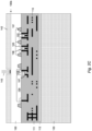
- a semiconductor substrate 90 disposed in a semiconductor wafer 9 which includes a well doping region 86 that forms the channel of the LDMOS transistor 81, a doping area 85 that forms a drift region.
- a gate electrode 88 is disposed on a gate oxide on the semiconductor substrate 90.
- Doping region 78 establishes the source and doping region 79 establishes the drain of the LDMOS transistor.
- One or more dielectric layers 91 are provided to establish pre- and intermetal dielectric layers on the surface 90a of the semiconductor substrate 90.
- the dielectric layers 91 embed one or more layers of metal wirings 89. The wirings contact the doping regions and the gate electrode to carry signals and/or current into and from the drain and source doping regions and carry control signals to the gate electrode.
- the drain electrode is connected to wiring layer portion 885.
- the gate electrode is connected to wiring layer portion 888.
- the signals from both wiring layers are available adjacent the surface 90a of the wafer 9.
- a pad 96 provides a metal connection at the top surface of the dielectric 91 so that a signal or a high voltage output or a drain current is available to the outside of the device so that it can be connected to an external circuit.
- a passivation 92 covers the top side of the device except the pad areas.
- Isolation regions surrounding the LDMOS transistor such as deep trench isolations 99 isolate the transistor from other devices and structures integrated within the wafer.
- the wafer may include other power devices or a CMOS circuit 80 that comprises a p-channel transistor and an n-channel transistor.
- the CMOS circuit can include well doping regions 83, source/drain doping regions 84 and gate electrodes including gate oxides 87.
- the CMOS transistors may be isolated by shallow trenches 82.
- the CMOS circuit is connected to the wiring layers 89 to receive and output signals that may be used to control the operation of the LDMOS device.
- Such a high-voltage LDMOS transistor may be operated at about 0 V (Volt) for the source electrode and about 40 V to 100 V at the drain electrode so that transistors designed for high break down voltages may generate large depletion zones during operation that extend deep into the substrate. Such depletion zones may cause issues with parasitic capacitances and leakage currents that may degrade the performance of the transistor.
- SOI silicon on insulator
- a buried insulation region 98 such as a buried oxide that isolates the active regions of the wafer from the other portions of the wafer beneath the buried oxide.
- the thickness of the substrate of the active area of the transistor becomes limited on a SOI substrate.
- the use of a silicon on insulator substrate is complex to manufacture and expensive in terms of costs.
- the low thermal conductivity of the buried oxide layer makes it difficult to remove heat form the high voltage transistor during operation.
- a semiconductor product comprises the features of claim 1.
- the semiconductor wafer that includes already the structures on the frontside of the semiconductor wafer with the wiring levels and the dielectric layer already disposed on the wafer is mounted to a carrier wafer and is then flipped so that it can be thinned from the rear or backside on the rear or back surface.
- the thin substrate allows a processing from the backside such as generating doping areas so as to further improve the characteristics of the transistor.
- another wiring layer can be generated on the backside of the wafer to contact the substrate and to provide for an electrical path to elements accessible from the backside to the frontside of the wafer by a through silicon via (TSV).
- TSV through silicon via
- a first or semiconductor wafer which includes prefabricated portions of an LDMOS transistor is attached to a second or carrier wafer so that the frontside of the semiconductor wafer including the LDMOS transistor portion faces the carrier wafer.
- the composite wafer arrangement of semiconductor wafer and carrier wafer is then treated from the backside of the semiconductor wafer. Specifically, semiconductor material is removed from the first wafer on the rear or backside so that the wafer is substantially thinned.
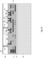
- FIG. 2A shows a first wafer 10 including the semiconductor substrate 100 of, e.g., p-type silicon that includes prefabricated portions of an LDMOS transistor 201.
- An n-type silicon wafer could also be useful.
- An epitaxial layer 100 that is grown on a silicon substrate is also possible.
- the epitaxial layer can be either n- or p-type or of undoped silicon.
- the shown doping areas 104, 105 and shallow trench isolations (STIs) 101 in substrate 100 have been fabricated while accessing the first wafer from the frontside 100a as described in connection with FIG. 1 .
- the first wafer 10 includes also a CMOS circuit 200 comprising a p-channel MOS transistor and an n-channel MOS transistor.
- a dielectric layer 111 is disposed on the frontside 100a of the first wafer, the top of the dielectric layer 111 is covered by passivation layer 112 forming a top surface 112a.
- the wirings 110 are embedded in the dielectric layer 111. While area 201 includes one or more high power and/or high voltage devices such as an LDMOS transistor, the area 200 includes one or more low voltage transistors such as a CMOS circuit.
- the planarized top surface 112a of the first wafer 10 is to be connected to a carrier wafer 120 by a bonding operation depicted at 140. No bonding pads are formed on the top surface of the dielectric layer 111.
- the connection between carrier wafer 600 and first wafer 10 at the surface of the dielectric layer 111 is made in accordance with commonly known process steps available to a skilled person to achieve a permanent bond between wafers 10 and 120.
- the carrier wafer 120 may be a semiconductor wafer as well, however, much less expensive than the device wafer in which the doping areas are included.
- the passivation layer 112 may be a composition of several layers.
- the final top layer of the passivation layer 112 may be silicon nitride and/or silicon oxynitride which may be deposited by PECVD.
- a bond oxide may be deposited on top of the passivation layer 112.
- the bond oxide (not shown in FIG. 2A ) may be deposited as a TEOS silicon dioxide by PECVD on top of the silicon nitride or the silicon oxynitride.
- CMP chemical mechanical polishing
- a sequence of PECVD TEOS depositions and CMP steps could be applied to achieve the required flatness.
- the surface of the bond oxide is activated by a plasma with an inert gas.
- the carrier wafer 120 is attached to the top surface of the device wafer 10 applying a suitable mechanical force or pressure.
- a low temperature bake is performed to strengthen the bonding.
- the baking process may be in the range of lower than 450°C, preferably lower than 400 °C.
- the bonding relies on Van-der-Waals forces between the top silicon dioxide surface of the bond oxide on top of the device wafer 10 and the silicon surface of the carrier wafer 120.
- adhesive bonding using polymer adhesives such as benzocyclobutene (BCB) or others may be used as well to achieve a reliable bonding between the device wafer and the carrier wafer.
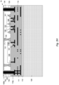
- the first wafer or device wafer 10 is treated from its backside after the first wafer 10 has been mounted to carrier wafer 120.
- the original backside 100c is treated such that material is removed from the backside 100c to substantially reduce the thickness of the first wafer 10 from the original thickness A to a desired thickness B.
- the backside 100c of the first wafer 10 is grinded as depicted with arrows 141.
- the thinning of the wafer 10 can include removal processes such as chemical etching like wet etching or dry etching or chemical-mechanical polishing. Any process that is capable of removing a substantial amount of substrate material from the first wafer 10 may be useful for the thinning process.
- the majority of the backside material can be removed by mechanical grinding followed by a chemical-mechanical polishing process and etchback to obtain a planarized surface 100b at the desired wafer thickness B after the thinning process.
- the backside surface 100b should have such a condition so that additional processing steps such as deep trench etching, via etching, doping, dopant implanting, deposition of metals and dielectrics are possible.
- the bulk of the silicon material is removed by backgrinding.
- the remaining thickness is measured.
- the polishing amount is adjusted according to the measured value of the thickness after backgrinding and the target for the final silicon thickness of the device wafer 10. In this approach a good wafer-to-wafer control of the final silicon thickness can be achieved with an acceptable intra-wafer uniformity of the silicon thickness.
- different dopant densities of the epitaxial layer and the substrate on which the epitaxial layer was grown may be used.
- the bulk of the silicon material is removed by backgrinding.
- a wet etchback is performed which stops selectively on the expitaxial layer owing to the different dopant densities of the substrate and the epitaxial layer and the selectivity of the etch process.
- a CMP process can be performed additionally.
- a good wafer-to-wafer control can be achieved in combination with a good intra-wafer uniformity.
- the final silicon thickness is the same or substantially the same as the thickness of the epitaxial silicon.
- the thickness B established after the thinning process 141 as shown in FIG. 2B is in the range of 2 ⁇ m to 50 ⁇ m.
- the thickness B is taken between the top surface 100a of the silicon material of the wafer 10 and the rear or back surface 100b after thinning from the backside of the wafer 10.
- the thickness may be preferably in the range of 2 ⁇ m to 25 ⁇ m. Most preferably, the thickness may be in the range of 3 ⁇ m to 20 ⁇ m.
- the active areas of high-voltage MOS transistors may have a depth so that the function of the transistor is guaranteed and the parasitic capacitance in the substrate is limited by the reduced, thinned thickness of the wafer.
- the manufacturing costs of a process using backside thinning are less than the manufacturing costs of using a conventional SOI substrate including generating complex buried isolation structures as described in connection with FIG. 1 .
- the thinned device wafer 10 exhibits several advantages that may not or not as easily be achieved with a conventional SOI wafer such as higher heat dissipation, lower parasitic capacitances, higher electrical currents etc. as described hereinbelow.
- the LDMOS transistor is completed with as such standardized processes, although performed from the rear or backside of the wafer.
- a resist mask 142 is applied on the thinned wafer backside 100b to define regions for doping or implantation 143.
- a masked implantation for a body contact of the LDMOS transistor 201 on the wafer backside is shown. After the implantation 143 the resist is masked is removed.
- alignment marks on the wafer are necessary which have been created by a frontside process and which have been made visible on the wafer backside.
- the thinned semiconductor wafer 10 allows a convenient generation of the doping processes from the backside 100b of the thinned wafer 10 that would be almost impossible to generate from its frontside 100a.
- the doping area 131 is annealed to smooth the doping and heal defects that were generated by the implantation 143 as shown in FIG. 2D .
- Annealing may be performed by a laser treatment of the thinned backside 100b as shown at 144 to maintain the available thermal budget of the to be generated LDMOS device and the other devices on the wafer such as the CMOS circuit.
- the laser thermal anneal (LTA) 144 may be performed after all implantations have been made to activate the dopants introduced into the silicon substrate on the backside.
- the wafer is exposed to very short heat pulses so that the heat can penetrate into the silicon only to a limited depth depending on pulse time, energy dose and wavelength.
- dopants can be activated on the wafer backside without ruining a metallization on the frontside which may be based on Aluminum (Al) and also without affecting the thermal budget of the devices.
- the depth of the thermal impact generated by the LTA is limited due to the nature of LTA so that the doping areas on the frontside of the wafer are not adversely affected. Dopants can be activated until a depth of about 2 ⁇ m with state of the art laser thermal annealing equipment.
- the laser thermal anneal may comprise a field that is stepped across the wafer backside surface, wherein several laser pulses may be applied on the wafer while the field stays on a location.
- the field may have rectangle or square size of, for example, 20 mm * 20 mm (millimeters) and the pulses may last for, for example, 200 ns to 300 ns (nanoseconds).
- Mask 145 is deposited and patterned on the backside 100b of wafer 10 to define areas to generate deep trenches into the substrate 100.
- Mask 145 may be a resist mask or may be a hard mask both of which withstand the deep trench reactive ion etching (RIE) process.
- RIE deep trench reactive ion etching
- a resist mask may be used to define the hard mask which is then used for the deep trench etch.
- the hard mask may be silicon dioxide.
- Deep trenches 146a, 146b are etched, for example, by an RIE dry etching process into the substrate 100 to end on the already present shallow trench isolations 101a and 101b, respectively, that have been processed from the frontside 100a of the wafer.
- the mask 145 of the deep trench isolation could be such that deep trench isolation are formed only at those positions where shallow trench isolations 101a, 101b exist on the frontside.
- the deep trench etch stops selectively on the bottom surface of the silicon dioxide that fills the shallow trench isolations 101a, 101b.
- deep trench isolations extend to the pre-metal dielectric 111. Alignment marks are required to position the mask on the backside relative to the shallow trench isolations of other structures on the frontside.
- a dielectric layer is deposited on the backside of the wafer so as to fill up the deep trenches 146a, 146b with dielectric material 132.
- the insulating material may be a silicon dioxide based dielectric.
- the insulating material should be processible at temperatures not above of 400 °C in order not to ruin the Al based metallization 110.
- a sub atmospheric CVD deposition with ozone/TEOS is useful to fill trenches 146a, 146b with oxide material 132.
- a high density plasma (HDP) CVD silicon dioxide deposition could be applied as well.
- a spin-on dielectric material such as a spin-on glass (SOG) or benzocyclobutene (BCB) is also possible that is applied to the wafer backside by a spin-on process.
- SOG spin-on glass
- BCB benzocyclobutene
- Other options for filling the trenches 146a, 146b with dielectric material are known to those skilled in the art.
- the lateral size of the deep trenches may depend on the voltage rating of the LDMOS transistor and the breakdown voltage and leakage of the silicon dioxide based dielectric material.
- the active area 104, 105 of the LDMOS transistor is isolated from other features in the semiconductor wafer 10 by the deep isolation trenches 132 plus the shallow trench isolations 101a, 101b.
- the deep trench isolations formed in deep trenches 146a, 146b form a barrier around the LDMOS transistor and isolate its structures including its doping regions from other structures on the wafer such as the CMOS circuit which comprises other doping regions.
- the horizontal portions of the silicon dioxide which is deposited on the silicon surface during the filling of the deep trenches may remain on the backside. If needed, the thickness of the silicon dioxide may be reduced which can be accomplished, for example, by CMP (chemical mechanical polishing).
- CMP chemical mechanical polishing
- via holes are etched to establish a connection to the metal wiring 110 disposed on the frontside of the wafer in the dielectric layer 111.
- the via holes penetrate the full thickness of the thinned wafer and extend from its front surface to its back surface so that such a via hole is also named through silicon via (TSV).
- TSVs enable an electrical connection from the frontside to the backside of wafer 10 so that an electrical signal or a current or a voltage can be passed from the frontside of the wafer to the backside where it can be further processed.
- the signal, current or voltage can be output from the die on the backside or can be passed again to the frontside through another TSV.
- a resist mask 147 is applied on the wafer backside to define the areas for the through silicon vias. Either the resist mask is used directly as mask for the via etch, as shown in FIG. 2G , or the resist mask is used to define a hard mask which is then used as the mask for the via etch.
- the through silicon via etch process may comprise at least two steps. A first step is the silicon etch which may selectively stop at the frontside 100a of the substrate 100 when the etch process reaches the pre-metal dielectric 111. In a second step the pre-metal dielectric 111 is etched so that the second step stops selectively on the bottom side of metal wiring 110a used in the frontside metallization.
- This metal wiring 110a may comprise a Ti/TiN barrier as the lowermost layer being closest to the silicon surface 100a.
- An Al layer may be disposed on the Ti/TiN barrier layer.
- the Ti/TiN barrier layer may comprise a layer of Ti and a layer of TiN disposed theron.
- the TSV etch process is controlled to stop on the Ti/TiN barrier layer of wiring layer 1 10a.
- the etch chemistry may comprise SF6, O2, HBr so that a via with high aspect ratio, e.g. in the range of about 15:1, is achieved so that the sidewalls of the TSVs have no significant taper and are almost vertical.
- the through silicon via may establish a contact to the lowest interconnect level or first metal layer which is the metal layer 110a closest to the front surface 100a of the wafer. It is also possible that the through silicon via extends to the bottom of a higher metal layer creating a contact to that interconnect level.
- the deep trench etch steps for the deep trenches and for the TSVs are performed with different etch masks, one for the deep trench isolations and another one for the through silicon vias. It is also possible to perform a combined etch step defining both simultaneously, the trenches for the deep trench isolations and the vias for the through silicon vias. In particular, if the silicon thickness after thinning is still high, the latter approach may be preferred. In this case, the etch step will stop on the boundary between silicon 100 and the dielectric, which is the dielectric of the shallow trenches such as 101a, 101b and the dielectric of the pre-/intermetal dielectric 111.
- TSV 148 is positioned next to the CMOS circuit 200
- TSV 149 is positioned next to the LDMOS transistor 201.
- a dielectric insulating liner 133 is deposited on the sidewalls of the TSVs followed by a conductive filling 134 establishing metal stud 134.
- Sub atmospheric CVD with ozone/TEOS may be used for conformal deposition of a dielectric liner in the TSVs.
- the dielectric liner prevents an electrical connection of the via to the silicon.
- the dielectric liner 133 must be opened at the bottom of the TSV before filling with conductive material.
- the conductive filling 134 may be a metal layer such as aluminum, tungsten or copper. The choice of the metal may depend on the lateral size and the aspect ratio of the TSV.
- a barrier layer is usually deposited, for example Ti/TiN. After metal filling the horizontal portions of the deposited conductive material are removed from the backside by etchback or CMP depending on the material used. As a result, the metal area 134 of the TSVs are available on the thinned backside 100b of wafer 10.
- a signal or current or voltage produced on the frontside of the wafer are available on its backside what is enabled by the thinned wafer 10 and would be more complicated to achieve or even impossible with conventional manufacturing processes that do not use a thinning of the device wafer when connected to a carrier wafer, as described above.
- the conductive filling 134 contacts the surface 110a of the wiring layer 110 that has been exposed in the via 149. Accordingly, an electrical contact is established between the wiring layer 110 embedded in the dielectric layer 111 on the frontside of the wafer 10 through the via 149 to the backside of the wafer 10.
- the portion of metal surface 110a is connected to the drain of the LDMOS transistor 201, the current from the drain is available at the conductive filling 134 on the backside of the wafer and can be accessed from externally of the device or can be routed to the backside to other devices (not shown in the drawings) such as other power MOS or bipolar transistors fabricated in the same wafer 10 or to the CMOS circuit 200. Accordingly, the drain connection of the LDMOS transistor is routed to the rear or backside of the wafer so that it can be connected to features accessible from the backside.
- a dielectric layer for example, a silicon dioxide layer 139 is deposited and opened at those positions where the metal fillings 134 disposed in the TSVs are located, where metal contacts are to be formed.
- Metal is deposited on the wafer backside on the silicon dioxide layer 139 and structured.
- An ohmic metal contact 135 is formed on the backside for the body contact of the LDMOS transistor.
- a metal wiring 136 on the silicon dioxide layer is formed as well. Bonding pads 138 are formed so that a current or voltage can be supplied to the external of the device.
- the thickness of the metal layer disposed on the wafer backside forming the bonding pads and backside wirings are sufficiently thick so that they can carry relatively large currents.
- the CMOS circuit may control the operation of the LDMOS device.
- the CMOS circuit may be operatively connected to the LDMOS device to control the switch state of the LDMOS device and switch the LDMOS device on or off depending on the power function to be performed.
- the CMOS circuit may be connected to the gate electrode of the LDMOS transistor to control the switch state of the LDMOS transistor. This connection may be established at the frontside of the wafer through the wiring layer 110.
- the CMOS circuit may as well be connected to a drain signal of the LDMOS transistor to control the switch state of the LDMOS transistor in response to the drain signal of the LDMOS transistor. This requires a connection from the drain to the CMOS circuit, for example, by use of a through silicon via that passes the drain signal available on the backside of the wafer to the CMOS circuit on the frontside.
- a passivation 137 is deposited on the wafer backside with opening of bonding pads. With the boding pads available on the backside, it can be considered to mount the finished wafer on another device wafer to realize a 3D integration.
- a layout of a power chip including the LDMOS and CMOS devices shown in FIGs. 2J comprises deep trench isolations such as 132a, 132b formed from the wafer backside which are used to effectively isolate single high voltage transistors from each other and from the chip area with low voltage transistors and passive devices as the standard CMOS devices.
- the deep trenches 132a, 132b including the shallow trenches 101a, 101b that cooperate with the deep trenches completely surround the high voltage transistors so as to form an edge termination for each of these transistors.
- FIG. 2J shows only a cross-section of the deep trench and shallow trench isolations, a skilled person will understand that such trenches form a continuous and contiguous isolation ring surrounding the LDMOS transistor.
- the logic and control circuit such as the CMOS circuit can be realized outside this isolation ring.
- the CMOS circuit may be part of the control circuit that controls the switch state of the LDMOS transistor.
- surrounding deep trench isolations can help to reduce leakage and parasitic capacitances. With deep trench isolations a denser packaging of low and high voltage transistors can be accomplished resulting in lower silicon area consumed.
- the bonding pads such as 138 are on the wafer backside, through silicon vias are necessary to connect metal pads on the wafer frontside with the bonding pads on the wafer backside. Depending on the size of the through silicon vias multiple vias can be used to establish a contact between the metal pad on the wafer frontside and the bonding pad on the backside.
- Through silicon vias can be used to integrate vertical high voltage transistors in a Power IC. With through silcon vias all terminals of a vertical high voltage transistor can be brought to the wafer backside. Through silicon vias could also be useful for specific lateral or vertical high voltage transistors. For instance, a through silicon via could connect a field plate on the wafer backside to an interconnect line on the frontside.
- a connection from the wiring layer 110 through the via 148 to the external of the wafer may be made with a bond wire (not shown) replacing the corresponding bonding pad 138.
- a bond wire (not shown) replacing the corresponding bonding pad 138.
- the bond wire is bonded to the bottom of the through silicon via which may be the wiring layer 110 and extends through the TSV to a terminal external to the wafer.
- a doped semiconductor substrate is provided such as a semiconductor wafer (step 401).
- the semiconductor wafer is processed from its frontside (step 402) which includes the formation of one or more doping areas that may comprise doping areas at a higher dopant concentration or a lower concentration or doping wells.
- Frontside processing may also comprise the formation of gate oxides and gate electrodes.
- the gate electrodes and gate oxides may be located in trenches within the substrate or on top of the surface of the substrate.
- Frontside processing includes also the deposition of one or more dielectric layers on top of the frontside of the substrate.
- the one or more dielectric layers embed one or more metal layers that provide wirings or interconnections between the doping areas and gate electrodes within one of the devices and also between one device and another device.
- the wafer After having been processed from the frontside the wafer is attached or bonded to a carrier wafer (step 403).
- the frontside of the semiconductor wafer in particular the surface of the dielectric layer that embeds the wirings, is bonded to a surface of the carrier wafer by suitable bonding processes.
- the semiconductor wafer is then thinned from the backside (step 404), which includes the removal of substrate material from the backside of a semiconductor wafer.
- the backside processing includes several steps to complete the device that have already been pre-processed from the frontside and includes steps to make interconnections between frontside and backside of the wafer and between one or more devices on the wafer.
- FIGs. 4A and 4B show a diagram depicting the steps and options for the process flow of the backside processing (step 405) in more detail.
- Multiple implantations are performed with a corresponding photomask followed by a laser thermal anneal (step 501).
- Implantations can have several purposes: contact implants for contacting terminals of the high voltage transistor on the backside, formation of deep doping regions when implantation from wafer frontside is technically not feasible anymore, a collector implant for a vertical IGBT, (not covered by the patent) etc.
- Laser thermal annealing facilitates activation of the introduced dopants without heat exposure to the wafer frontside.
- Deep trench isolations are formed from the backside which extend vertically through all silicon from the wafer backside to the wafer frontside so that they can effectly isolate the high voltage transistors from the standard CMOS area of the die (step 502).
- a deep trench isolation ring surrounding the high voltage transistor can be formed.
- the deep trenches can land on the bottom of shallow trench isolations formed on the wafer frontside which is the preferred way. They can also land on the pre-metal dielectric disposed on the wafer frontside.
- Deep trenches can be etched using standard etching techniques. The filling could be accomplished with sub atmospheric ozone/TEOS CVD, high density plasma (HDP) CVD silicon dioxide deposition, or spin-on dielectrics (e.g. benzocyclobutene) or similar materials.
- HDP high density plasma
- the formation of through silicon vias accomplish contacts to metal plates formed on a frontside interconnect level to make the electrical signals from the wafer frontside available to the wafer backside where the bonding pads are formed (step 503).
- the etching of the via may comprise two steps, a silicon etch which goes through the silicon substrate and an oxide etch which goes through the pre-metal dielectric stopping finally at the bottom the metal plate.
- the etching of the silicon part can be combined with the etching of the deep trenches for isolation.
- a dielectric liner is deposited and opened at the bottom before the via is filled with metal.
- aluminum, tungsten or copper can be used as conductive material.
- a dielectric layer like silicon dioxide deposited on the wafer backside can improve the isolation of the high voltage transistor, reduce leakage currents and avoid to a large extent parasitic capacitance (step 504). Higher breakdown voltages can be obtained for LDMOS transistors.
- the thickness of the silicon dioxide will depend on the device.
- the oxide on the backside also isolates interconnect lines on the wafer backside from the device silicon. Windows in the silicon dioxide layer can be etched to allow heat dissipation if needed.
- a field plate formed below the drift region can improve the tradeoff between on-state resistance and breakdown voltage of a LDMOS transistor (step 506).
- a multilevel metallization can be realized on the wafer backside. Large and thick metal lines made of aluminum or copper can be used to transport large currents with low resistance.
- the dielectrics used in this metallization scheme could be PECVD silicon dioxide or spin-on dielectrics (e.g. benzocyclobutene).
- the metallization includes the formation of bonding pads (step 507).
- a standard final passivation with openings of the bonding pads can be applied on the wafer backside (step 508).
- the doping areas can be interconnected with each other. It is also possible to connect the backside doping regions to features on the frontside of the wafer such as the wiring layer in the dielectric on the frontside of the wafer, wherein one or more metal contacts are formed in through silicon vias that traverse the full depth of the thinned wafer.
- the LMOS devices fabricated on a wafer can be separated by dicing or sawing so that individual integrated circuits are generated. (not part of the claimed invention).
- the carrier wafer is diced at the same time and remains connected to the dies of the device wafer.
- a power on chip system including several of said high-voltage and/or power devices can be achieved.
- the process allows to generate a laterally double diffused MOS transistor (LDMOS), a vertical double diffused MOS transistor (VDMOS), a vertical trench MOS transistor, a lateral gate insulated bipolar transistor, a vertical gate insulated bipolar transistor (IGBT), a vertical bipolar transistor, a junction gate field effect transistor (JFET), a super junction LDMOS transistor and a thyristor according to the above described process which includes the forming of a doping region from the frontside, the bonding of the device wafer to a carrier wafer and the thinning of the wafer backside.
- One or more of said transistors or a combination one or more of said transistors are disposed in and monolithically integrated in the semiconductor wafer.
- the transistors generate signals during operation, wherein such electrical signals are made available at the second surface of the semiconductor wafer to be output or distributed therefrom.
- the electrical signal can be output from the device and supplied to external circuitry.
- the electrical signal is available at an electrode of the device present on the thinned backside of the wafer or is passed through a through silicon via from the frontside to the backside of the wafer.
- MOS transistors such as LDMOS transistors can be economically fabricated together or in parallel to NPN or PNP bipolar transistors using many same process steps in parallel so that a power on chip (POC) system can be monolithically realized.
- POC power on chip
- FIGs. 5 to 10 show several examples of transistors that can be fabricated with the process described Fig. 5 , 7-10 are not covered by the present invention, which remains defined by the appended claims, while Fig. 6 shows a LDMOSFET as in the invention.
- Fig. 6 shows a LDMOSFET as in the invention.
- One or more of such transistors of the same type or a combination of different types can be combined on one die.
- FIG. 5 shows an LDMOS transistor which includes that the wafer is attached to a carrier wafer (not shown in FIG. 5 ) and is thinned to achieve a backside surface.
- the LDMOS transistor has source and drain contacts on the backside of the wafer.
- the LDMOS transistor comprises a source doping region 603, an n-drift doping region 608 beneath a shallow trench isolation 601 and a drain doping region 605.
- a gate polysilicon electrode 606 is disposed above a gate oxide 607.
- P-well 604 is disposed below gate electrode 607 forming the channel of the LDMOS transistor.
- the doping areas of the LDMOS transistor are formed from the frontside 600a of a p-epitaxial substrate 600.
- the backside 600b of the substrate 600 was thinned according to the methods described above.
- the backside 600b of the substrate is covered with a backside oxide 644.
- sinker dopings are implanted into the substrate from its frontside 600a, the sinker dopings are in contact with doping regions and metal filled trenches formed from the backside.
- an n-sinker doping arrangement 656a, 656b, 656c is formed from the frontside 600a of the substrate in and close to the drain region 605.
- the first n-sinker doping region 656a is implanted at a first relatively low depth in the drain area 609.
- a second n-sinker doping region 656b is formed at a depth lower than the first doping region 656a.
- a third and lowest doping area 656c is formed from the frontside of the wafer into the drain area of the LDMOS transistor having a depth greater than the depths of the first and the second n-sinker doping regions.
- the different depths can be controlled by different implantation energies of the ions during the n-sinker doping process.
- a similar process applies to the forming of a backside contact to the source area 603, wherein an n-sinker doping arrangement of three n-sinker doping regions 660a, 660b, 660c having different depths within the substrate are generated from the frontside 600a of the wafer.
- a trench is formed in the backside oxide 644 at a position where the n-sinker dopings are. The trench may optionally extend into the substrate 600.
- a tilted n+ implantation 657 as shown is formed from the backside into the substrate 600. The n+ implantation 657 may be untilted as well.
- Another trench is formed from the backside into the backside oxide 644 and optionally into the substrate 600 to contact the source sinker doping regions.
- n+ doping region 661 is formed to contact the n-sinker doping arrangement 660a, 660b, 660c. Then, a metallization is deposited on the backside that fills the trenches formed in the backside oxide 644. The backside metallization may be patterned to obtain the drain and source contacts 658, 662. The backside contact to the sinker doping arrangement 660a, 660b, 660c can be combined with a p+ doping region 663 which has the function of a body contact. In this case, the metal contact 662 contacts both, the n+ backside doping 661 and the p+ body doping 663.
- the n-sinkers and backside contacts are usually formed in parallel for source and drain at the same time. It is also possible to form only one backside contact for the source or one backside contact for the drain.
- the forming of a backside contact in accordance with FIG. 5 increases the capability to handle higher currents per silicon area for large LDMOS devices. Large metal plates such as metal plate 658 for the drain backside contact and/or metal plate 662 for the source backside contact are able to carry sufficient current for the source and/or the drain of the LDMOS power device, and assist in a dissipation of the heat generated by the large currents.
- an LDMOS transistor is shown fabricated according to the methods described above that exhibits a field plate 650 on the backside of the wafer.
- the frontside of the wafer is connected to a carrier wafer (not shown in FIG. 6 ).
- the substrate 600 has been thinned from its backside, then covered with backside oxide 644.
- the backside oxide 644 is covered with a metal plate 650 which functions as a field plate arranged below the LDMOS doping regions 604, 608.
- the field plate can be connected to the source by a through silicon via (TSV) fabricated as explained above and indicated at 651a, which means that the field plate 650 can be connected through the TSV to the frontside of the wafer where the source doping areas 602, 603 are available in the wiring layer 610.
- TSV through silicon via
- an external voltage or external potential can be applied to field plate 650 on its external connection 651.
- the electric field of the field plate can assist in the depletion of the n-drift region 608 in the off-state which allows higher dopant densities for the n-drift region.
- the electric field can increase the conductivity of the n-drift region in the on-state.
- FIG. 6 shows an n-LDMOS transistor
- a p-LDMOS transistor can be formed in a corresponding way using opposite doping polarities.
- FIG. 7 shows a super junction LDMOS transistor.
- Rdson on-resistance
- breakdown voltage can be achieved with alternating n- and p-pillars arranged in the drift region of an LDMOS transistor.
- the drift region is arranged between source doping region 603 and drain doping region 605.
- a higher dopant density can be used for the n-pillars for a given breakdown voltage which finally results in a lower Rdson.
- the conventional super junction LDMOS transistor suffers from the so-called substrate-assisted depletion (SAD), with which the additional vertical depletion of the n-pillars by the p-substrate destroys the charge balance which is critical to achieve the high breakdown voltage.
- SAD substrate-assisted depletion
- a vertical electrical field increases towards the drain.
- the super junction LDMOS transistor where the wafer is attached to a carrier wafer (not shown in FIG. 7 ) and is thinned to achieve a backside surface 100b of the substrate so that the thinned backside surface reaches and is in contact with the bottom surfaces of the n-and p-pillars is shown in FIG. 7 .
- a silicon dioxide 655 is deposited on the thinned backside 100b of the substrate.
- the substrate-assisted depletion (SAD) is avoided because there is substantially no silicon substrate beneath the p-well 604 and the n- and p-pillars 608, 609 of the drift area of the LDMOS transistor.
- FIG. 7 shows a super junction n-LDMOS transistor, while a super junction p-LDMOS transistor can be formed in a corresponding way with opposite doping polarities.
- FIG. 8 shows a vertical DMOS transistor, where the wafer is attached to a carrier wafer (not shown in FIG. 8 ) and is thinned to achieve a backside surface 100b.
- the vertical DMOS transistor comprises an n-drift region 702 disposed in the substrate.
- P-body doping regions 704 include n+ source doping areas 705.
- a JFET doping region 703 may be formed between the p body regions 704.
- a polysilicon gate electrode 706 is disposed on a gate oxide 707 extending from one n+ source doping region 705 to another n+ source doping region 705.
- a p+ body contact 704a is disposed within the p body region 704 connected to the n+ source region 705.
- a shallow trench isolation 701 is formed from the frontside of the wafer. Then, the frontside of the wafer is connected to a carrier wafer (not shown) so that the backside of the wafer can be thinned up to a surface 100b.
- a deep trench isolation 732 is formed from the thinned backside to land on the bottom surface of the shallow trench isolation 701. Trench isolations 701, 732 surround the vertical DMOS transistor and isolate it from other features or circuits integrated on the same die.
- an n+ drain contact implantation 731 performed from the wafer backside. The implantation of the n+ drain contact 731 can be followed by a laser thermal anneal (LTA).
- An ohmic metal contact 735 is formed on the wafer backside on the n+ drain contact 731 in the region of the vertical DMOS transistor.
- the backside drain contact 735 may be electrically connected by a metal line to other elements on the wafer backside or may be electrically contacted to features on the frontside of the wafer by a through silicon via, the generation of which has been described above.
- a vertical trench MOS transistor can be formed in a similar way, wherein the gate oxide and the gate electrode are formed in a trench extending from the frontside of the wafer into the substrate.
- FIG. 9 shows a vertical isolated gate bipolar transistor (IGBT) which has a structure similar to the vertical DMOS transistor of FIG. 8 , furthermore comprising a p+ collector region 831 formed adjacent to the thinned surface 100b.
- An n+ buffer layer 833 can be formed from the thinned backside 100b within the n drift region 802 before the p+ collector 831 is formed.
- the n+ buffer layer 833 is optional.
- the collector implantation 831 is connected to a metal backside connection 835.
- the electrodes 842 are the emitter electrodes of the vertical IGBT connected to the emitter doping region 805, wherein the p doping regions 804 are the base electrodes.
- the p+ drain collector region 831 is implanted from the wafer backside followed by laser thermal annealing. Often times, the n+ buffer layer 833 is used buried between the p+ collector 831 and the n drift region 802. The respective implantation for the n+ buffer layer 833 is performed from the thinned wafer backside.
- An ohmic metal contact 835 is formed on the wafer backside in the IGBT region.
- the collector plate 835 of the IGBT can be electrically contacted by a through silicon via to the frontside of the wafer or by a metal line to other elements on the wafer backside. Deep trench isolations 832 formed from the wafer backside and shallow trench isolations 801 formed from the wafer frontside that surround the vertical IGBT and that isolates the area of the vertical IGBT from other structures also formed in the same semiconductor die.
- FIG. 10 shows a vertical bipolar transistor, where the wafer is attached to a carrier wafer (not shown in FIG. 10 ) and is thinned to achieve a backside surface. Shown is a vertical NPN bipolar transistor while a vertical PNP bipolar transistor can be formed in a corresponding way with opposite doping polarities.
- the vertical bipolar transistor shown in FIG. 10 comprises a base doping region 904 formed from the frontside of the wafer.
- the base 904 includes p+ base contact implantations 904a and an n-emitter implantation 903 including an n+ emitter contact implantation 903a, all processed from the frontside of the wafer.
- the n-collector 902 is formed between the base area 904 and the wafer backside.
- an n+ collector implant 934 is formed adjacent to the thinned wafer backside.
- the n+ collector contact implantation is performed from the wafer backside followed by laser thermal annealing.
- An ohmic metal contact 935 is formed on the thinned wafer backside in the region of the NPN bipolar transistor.
- the collector plate 935 of the transistor can be electrically contacted by a through silicon via to structures on the frontside of the wafer or by a metal line to elements present on the wafer backside.
- Deep trench isolations 932 formed from the thinned wafer backside and shallow trench isolations 901 formed from the wafer frontside surround the vertical NPN bipolar transistor.
- a vertical thyristor can be fabricated in a similar way. It has a NPNP structure with the cathode and the gate on the frontside of the wafer.
- the anode of a vertical thyristor can be realized on the thinned wafer backside by P+ implantation followed by laser thermal annealing and forming an ohmic metal contact on that surface.
- the backside processing can also be useful to fabricate a junction gate field effect transistor (JFET).
- JFET junction gate field effect transistor
- the current flowing through the channel is modulated by the combined action of two gates which are in contact with doping regions having the opposite polarity as the channel region.
- the second gate of the JFET can be formed on the thinned wafer backside. Both gates are ohmic metal contacts.
- the gates are each in contact with a P doping region.
- the P doping region can be created by implantation and laser thermal annealing on the thinned backside.
- TSV the gate on the wafer backside can be electrically shorted with the gate on the frontside as required for this device.
- a p-channel JFET can be formed in a corresponding way with opposite doping polarities.
Description
- The invention relates to a semiconductor product that can be fabricated according to a method that processes a semiconductor wafer from a first surface and uses a carrier wafer to which the semiconductor wafer is attached to process the semiconductor wafer from a second surface thereof.
- Semiconductor wafers are used to manufacture semiconductor devices including bipolar and MOS transistors designed for high-voltage or power applications. According to a conventional manufacturing process, doping regions and isolation regions are all processed from one side of the semiconductor wafer. A typical example of a high-voltage MOS transistor is a laterally diffused MOS transistor (LDMOS) as shown in
FIG. 1 the constitution of which is briefly described below. - Provided is a
semiconductor substrate 90 disposed in asemiconductor wafer 9 which includes a welldoping region 86 that forms the channel of theLDMOS transistor 81, adoping area 85 that forms a drift region. Agate electrode 88 is disposed on a gate oxide on thesemiconductor substrate 90.Doping region 78 establishes the source anddoping region 79 establishes the drain of the LDMOS transistor. One or moredielectric layers 91 are provided to establish pre- and intermetal dielectric layers on thesurface 90a of thesemiconductor substrate 90. Thedielectric layers 91 embed one or more layers ofmetal wirings 89. The wirings contact the doping regions and the gate electrode to carry signals and/or current into and from the drain and source doping regions and carry control signals to the gate electrode. For example, the drain electrode is connected towiring layer portion 885. The gate electrode is connected towiring layer portion 888. The signals from both wiring layers are available adjacent thesurface 90a of thewafer 9. Apad 96 provides a metal connection at the top surface of the dielectric 91 so that a signal or a high voltage output or a drain current is available to the outside of the device so that it can be connected to an external circuit. Apassivation 92 covers the top side of the device except the pad areas. - Isolation regions surrounding the LDMOS transistor such as
deep trench isolations 99 isolate the transistor from other devices and structures integrated within the wafer. The wafer may include other power devices or aCMOS circuit 80 that comprises a p-channel transistor and an n-channel transistor. The CMOS circuit can include well doping regions 83, source/drain doping regions 84 and gate electrodes includinggate oxides 87. The CMOS transistors may be isolated byshallow trenches 82. The CMOS circuit is connected to thewiring layers 89 to receive and output signals that may be used to control the operation of the LDMOS device. - Such a high-voltage LDMOS transistor may be operated at about 0 V (Volt) for the source electrode and about 40 V to 100 V at the drain electrode so that transistors designed for high break down voltages may generate large depletion zones during operation that extend deep into the substrate. Such depletion zones may cause issues with parasitic capacitances and leakage currents that may degrade the performance of the transistor.
- Conventional manufacturing processes employ a silicon on insulator (SOI) substrate that includes a buried
insulation region 98 such as a buried oxide that isolates the active regions of the wafer from the other portions of the wafer beneath the buried oxide. The thickness of the substrate of the active area of the transistor becomes limited on a SOI substrate. However, the use of a silicon on insulator substrate is complex to manufacture and expensive in terms of costs. Furthermore, the low thermal conductivity of the buried oxide layer makes it difficult to remove heat form the high voltage transistor during operation. - The fabrication of vertical high voltage transistors is difficult with a SOI substrate according to the conventional approach because access to the lower electrodes may be complicated and vertical high voltage transistors are difficult to integrate with lateral transistors.
- For example the documents
US 2009/258472 A1 orUS6310378B1 disclose power devices fabricated on a SOI substrate. - It is therefore desirable to provide a semiconductor product, for example a high-voltage and/or power device that is less complex, having predictable parameters and is less expensive.
- According to an aspect of the present disclosure, a semiconductor product comprises the features of
claim 1. - According to a method of fabricating a semiconductor device, the semiconductor wafer that includes already the structures on the frontside of the semiconductor wafer with the wiring levels and the dielectric layer already disposed on the wafer is mounted to a carrier wafer and is then flipped so that it can be thinned from the rear or backside on the rear or back surface. This allows to generate a relatively thin substrate that avoids overly large parasitic capacitances, even when the transistor is operated at high voltages. Furthermore, the thin substrate allows a processing from the backside such as generating doping areas so as to further improve the characteristics of the transistor. Also, another wiring layer can be generated on the backside of the wafer to contact the substrate and to provide for an electrical path to elements accessible from the backside to the frontside of the wafer by a through silicon via (TSV). The backside metal contact and the TSVs achieve additional flexibility for the wiring of the circuit.
- Both the foregoing general description and the following detailed description are intended to provide an overview or framework for understanding the nature and character of the disclosure. The accompanying drawings are included to provide a further understanding of the process of fabrication of the claimed device. The drawings together with the description serve to explain the principles and operation of the concepts disclosed. Similar, identical or corresponding elements in different figures of the drawings are denoted with the same numerals.
- In the drawings:
- FIG. 1
- shows a conventional LDMOS transistor;
- FIGs. 2A to 2J
- show process steps of the fabrication of an LDMOS transistor;
- FIG. 3
- shows a diagram depicting a process flow of a method to fabricate one or more transistors on a wafer;
- FIGs. 4A to 4B
- show a diagram depicting a more detailed process flow of the method to fabricate one or more transistors;
- FIG. 5
- shows an LDMOS transistor not according to the invention using sinker dopings and backside connections;
- FIG. 6
- shows an LDMOS transistor using a field plate;
- FIG. 7
- shows a super junction laterally diffused MOS transistor not according to the invention;
- FIG. 8
- shows a vertical double diffused MOS transistor not according to the invention;
- FIG. 9
- shows a vertical insulated gate bipolar transistor not according to the invention;
- FIG. 10
- shows a vertical bipolar transistor not according to the invention.
- According to
FIGs. 2A to 2J , a first or semiconductor wafer which includes prefabricated portions of an LDMOS transistor is attached to a second or carrier wafer so that the frontside of the semiconductor wafer including the LDMOS transistor portion faces the carrier wafer. The composite wafer arrangement of semiconductor wafer and carrier wafer is then treated from the backside of the semiconductor wafer. Specifically, semiconductor material is removed from the first wafer on the rear or backside so that the wafer is substantially thinned. Then, several process steps are performed from the backside to complete the transistor devices including doping, implantation, trench etching, depositing of isolation layers to fill the trenches and isolate the transistors, etching through vias and depositing of conductive layers like metal layers to provide contact to the active areas of the backside of the wafer and provide contact to the wiring layers on the frontside. - In detail,
FIG. 2A shows afirst wafer 10 including thesemiconductor substrate 100 of, e.g., p-type silicon that includes prefabricated portions of anLDMOS transistor 201. An n-type silicon wafer could also be useful. Anepitaxial layer 100 that is grown on a silicon substrate is also possible. The epitaxial layer can be either n- or p-type or of undoped silicon. The showndoping areas substrate 100 have been fabricated while accessing the first wafer from the frontside 100a as described in connection withFIG. 1 . Thefirst wafer 10 includes also aCMOS circuit 200 comprising a p-channel MOS transistor and an n-channel MOS transistor. Adielectric layer 111 is disposed on the frontside 100a of the first wafer, the top of thedielectric layer 111 is covered bypassivation layer 112 forming atop surface 112a. Thewirings 110 are embedded in thedielectric layer 111. Whilearea 201 includes one or more high power and/or high voltage devices such as an LDMOS transistor, thearea 200 includes one or more low voltage transistors such as a CMOS circuit. - The planarized
top surface 112a of thefirst wafer 10 is to be connected to acarrier wafer 120 by a bonding operation depicted at 140. No bonding pads are formed on the top surface of thedielectric layer 111. The connection betweencarrier wafer 600 andfirst wafer 10 at the surface of thedielectric layer 111 is made in accordance with commonly known process steps available to a skilled person to achieve a permanent bond betweenwafers carrier wafer 120 may be a semiconductor wafer as well, however, much less expensive than the device wafer in which the doping areas are included. - One example of a bonding process is described below. The
passivation layer 112 may be a composition of several layers. The final top layer of thepassivation layer 112 may be silicon nitride and/or silicon oxynitride which may be deposited by PECVD. Then, a bond oxide may be deposited on top of thepassivation layer 112. The bond oxide (not shown inFIG. 2A ) may be deposited as a TEOS silicon dioxide by PECVD on top of the silicon nitride or the silicon oxynitride. Then, a chemical mechanical polishing (CMP) may be performed to planarize the surface of the bond oxide and ensure sufficient flatness thereof. A sequence of PECVD TEOS depositions and CMP steps could be applied to achieve the required flatness. Then, the surface of the bond oxide is activated by a plasma with an inert gas. Then, thecarrier wafer 120 is attached to the top surface of thedevice wafer 10 applying a suitable mechanical force or pressure. A low temperature bake is performed to strengthen the bonding. The baking process may be in the range of lower than 450°C, preferably lower than 400 °C. In theory, it is believed that the bonding relies on Van-der-Waals forces between the top silicon dioxide surface of the bond oxide on top of thedevice wafer 10 and the silicon surface of thecarrier wafer 120. As an alternative, for example, adhesive bonding using polymer adhesives such as benzocyclobutene (BCB) or others may be used as well to achieve a reliable bonding between the device wafer and the carrier wafer. - As shown in
FIG. 2B , the first wafer ordevice wafer 10 is treated from its backside after thefirst wafer 10 has been mounted tocarrier wafer 120. Theoriginal backside 100c is treated such that material is removed from thebackside 100c to substantially reduce the thickness of thefirst wafer 10 from the original thickness A to a desired thickness B. For example, thebackside 100c of thefirst wafer 10 is grinded as depicted witharrows 141. The thinning of thewafer 10 can include removal processes such as chemical etching like wet etching or dry etching or chemical-mechanical polishing. Any process that is capable of removing a substantial amount of substrate material from thefirst wafer 10 may be useful for the thinning process. For example, the majority of the backside material can be removed by mechanical grinding followed by a chemical-mechanical polishing process and etchback to obtain aplanarized surface 100b at the desired wafer thickness B after the thinning process. Thebackside surface 100b should have such a condition so that additional processing steps such as deep trench etching, via etching, doping, dopant implanting, deposition of metals and dielectrics are possible. - In one approach, the bulk of the silicon material is removed by backgrinding. The remaining thickness is measured. In a subsequent CMP process the polishing amount is adjusted according to the measured value of the thickness after backgrinding and the target for the final silicon thickness of the
device wafer 10. In this approach a good wafer-to-wafer control of the final silicon thickness can be achieved with an acceptable intra-wafer uniformity of the silicon thickness. - In another approach, different dopant densities of the epitaxial layer and the substrate on which the epitaxial layer was grown may be used. The bulk of the silicon material is removed by backgrinding. Then, a wet etchback is performed which stops selectively on the expitaxial layer owing to the different dopant densities of the substrate and the epitaxial layer and the selectivity of the etch process. Then, a CMP process can be performed additionally. With this approach a good wafer-to-wafer control can be achieved in combination with a good intra-wafer uniformity. The final silicon thickness is the same or substantially the same as the thickness of the epitaxial silicon.
- While the thickness A of the original
first wafer 10 is in the range of 700 µm (micrometers) or at least more than 500 µm, the thickness B established after the thinningprocess 141 as shown inFIG. 2B is in the range of 2 µm to 50 µm. The thickness B is taken between thetop surface 100a of the silicon material of thewafer 10 and the rear or backsurface 100b after thinning from the backside of thewafer 10. The thickness may be preferably in the range of 2 µm to 25 µm. Most preferably, the thickness may be in the range of 3 µm to 20 µm. The active areas of high-voltage MOS transistors may have a depth so that the function of the transistor is guaranteed and the parasitic capacitance in the substrate is limited by the reduced, thinned thickness of the wafer. - The handling of carrier wafers and the performance of thinning processes are commonly known and understood operations in the field of semiconductor wafer processing and manufacturing of electronic circuits. Fabrication tools to perform these processes are available of the shelf so that the described processes can be well implemented and achieve predictable and reliable results although they require only moderate expenses.
- Accordingly, the manufacturing costs of a process using backside thinning are less than the manufacturing costs of using a conventional SOI substrate including generating complex buried isolation structures as described in connection with
FIG. 1 . Furthermore, the thinneddevice wafer 10 exhibits several advantages that may not or not as easily be achieved with a conventional SOI wafer such as higher heat dissipation, lower parasitic capacitances, higher electrical currents etc. as described hereinbelow. - As described in connection with
FIGs. 2C to 2J , the LDMOS transistor is completed with as such standardized processes, although performed from the rear or backside of the wafer. As shown inFIG. 2C , a resistmask 142 is applied on the thinnedwafer backside 100b to define regions for doping orimplantation 143. InFIG. 2C , a masked implantation for a body contact of theLDMOS transistor 201 on the wafer backside is shown. After theimplantation 143 the resist is masked is removed. - Several different masked implantations can be applied on the wafer backside for different purposes in connection with the shown LDMOS transistor or with other high voltage transistors on the wafer. Other doping areas such as, for example, buried doping areas can be implanted in the substrate to enhance the transistor characteristics.
- For a proper alignment of the
photo mask 142 in the masking step performed on the wafer backside to the structures on the wafer frontside such as thedoping areas wiring layer 110, alignment marks on the wafer are necessary which have been created by a frontside process and which have been made visible on the wafer backside. There are several techniques available to a skilled person to accomplish such alignment marks. The thinnedsemiconductor wafer 10 allows a convenient generation of the doping processes from thebackside 100b of the thinnedwafer 10 that would be almost impossible to generate from its frontside 100a. - After the implantation of
dopant 143 and after the removal of resistmask 142, thedoping area 131 is annealed to smooth the doping and heal defects that were generated by theimplantation 143 as shown inFIG. 2D . Annealing may be performed by a laser treatment of the thinnedbackside 100b as shown at 144 to maintain the available thermal budget of the to be generated LDMOS device and the other devices on the wafer such as the CMOS circuit. The laser thermal anneal (LTA) 144 may be performed after all implantations have been made to activate the dopants introduced into the silicon substrate on the backside. During laser thermal annealing the wafer is exposed to very short heat pulses so that the heat can penetrate into the silicon only to a limited depth depending on pulse time, energy dose and wavelength. In this way, dopants can be activated on the wafer backside without ruining a metallization on the frontside which may be based on Aluminum (Al) and also without affecting the thermal budget of the devices. The depth of the thermal impact generated by the LTA is limited due to the nature of LTA so that the doping areas on the frontside of the wafer are not adversely affected. Dopants can be activated until a depth of about 2 µm with state of the art laser thermal annealing equipment. - In an embodiment, the laser thermal anneal may comprise a field that is stepped across the wafer backside surface, wherein several laser pulses may be applied on the wafer while the field stays on a location. For example, the field may have rectangle or square size of, for example, 20 mm * 20 mm (millimeters) and the pulses may last for, for example, 200 ns to 300 ns (nanoseconds).
- As shown in
FIG. 2E , anothermask 145 is deposited and patterned on thebackside 100b ofwafer 10 to define areas to generate deep trenches into thesubstrate 100.Mask 145 may be a resist mask or may be a hard mask both of which withstand the deep trench reactive ion etching (RIE) process. In the case of a hard mask, a resist mask may be used to define the hard mask which is then used for the deep trench etch. The hard mask may be silicon dioxide.Deep trenches substrate 100 to end on the already presentshallow trench isolations - As shown in
FIG. 2E , themask 145 of the deep trench isolation could be such that deep trench isolation are formed only at those positions whereshallow trench isolations shallow trench isolations pre-metal dielectric 111. Alignment marks are required to position the mask on the backside relative to the shallow trench isolations of other structures on the frontside. - As next shown in connection with
FIG. 2F , a dielectric layer is deposited on the backside of the wafer so as to fill up thedeep trenches dielectric material 132. The insulating material may be a silicon dioxide based dielectric. The insulating material should be processible at temperatures not above of 400 °C in order not to ruin the Al basedmetallization 110. A sub atmospheric CVD deposition with ozone/TEOS is useful to filltrenches oxide material 132. A high density plasma (HDP) CVD silicon dioxide deposition could be applied as well. As another alternative a spin-on dielectric material such as a spin-on glass (SOG) or benzocyclobutene (BCB) is also possible that is applied to the wafer backside by a spin-on process. Other options for filling thetrenches active area semiconductor wafer 10 by thedeep isolation trenches 132 plus theshallow trench isolations deep trenches - The horizontal portions of the silicon dioxide which is deposited on the silicon surface during the filling of the deep trenches may remain on the backside. If needed, the thickness of the silicon dioxide may be reduced which can be accomplished, for example, by CMP (chemical mechanical polishing).
- Turning now to
FIG. 2G , via holes are etched to establish a connection to themetal wiring 110 disposed on the frontside of the wafer in thedielectric layer 111. The via holes penetrate the full thickness of the thinned wafer and extend from its front surface to its back surface so that such a via hole is also named through silicon via (TSV). The TSVs enable an electrical connection from the frontside to the backside ofwafer 10 so that an electrical signal or a current or a voltage can be passed from the frontside of the wafer to the backside where it can be further processed. The signal, current or voltage can be output from the die on the backside or can be passed again to the frontside through another TSV. - As shown in
FIG. 2G , a resistmask 147 is applied on the wafer backside to define the areas for the through silicon vias. Either the resist mask is used directly as mask for the via etch, as shown inFIG. 2G , or the resist mask is used to define a hard mask which is then used as the mask for the via etch. The through silicon via etch process may comprise at least two steps. A first step is the silicon etch which may selectively stop at the frontside 100a of thesubstrate 100 when the etch process reaches thepre-metal dielectric 111. In a second step thepre-metal dielectric 111 is etched so that the second step stops selectively on the bottom side ofmetal wiring 110a used in the frontside metallization. Thismetal wiring 110a may comprise a Ti/TiN barrier as the lowermost layer being closest to thesilicon surface 100a. An Al layer may be disposed on the Ti/TiN barrier layer. The Ti/TiN barrier layer may comprise a layer of Ti and a layer of TiN disposed theron. The TSV etch process is controlled to stop on the Ti/TiN barrier layer ofwiring layer 1 10a. The etch chemistry may comprise SF6, O2, HBr so that a via with high aspect ratio, e.g. in the range of about 15:1, is achieved so that the sidewalls of the TSVs have no significant taper and are almost vertical. - The through silicon via may establish a contact to the lowest interconnect level or first metal layer which is the
metal layer 110a closest to thefront surface 100a of the wafer. It is also possible that the through silicon via extends to the bottom of a higher metal layer creating a contact to that interconnect level. - In
FIG. 2E and2G , the deep trench etch steps for the deep trenches and for the TSVs are performed with different etch masks, one for the deep trench isolations and another one for the through silicon vias. It is also possible to perform a combined etch step defining both simultaneously, the trenches for the deep trench isolations and the vias for the through silicon vias. In particular, if the silicon thickness after thinning is still high, the latter approach may be preferred. In this case, the etch step will stop on the boundary betweensilicon 100 and the dielectric, which is the dielectric of the shallow trenches such as 101a, 101b and the dielectric of the pre-/intermetal dielectric 111. In this case, an additional mask is necessary for opening the pre-/intermetal dielectric 111 for the through silicon vias to continue the etching until themetal layer 110a is reached. Turning again toFIG. 2G , twoTSVs TSV 148 is positioned next to theCMOS circuit 200,TSV 149 is positioned next to theLDMOS transistor 201. - Turning now to
FIG. 2H , a dielectric insulatingliner 133 is deposited on the sidewalls of the TSVs followed by a conductive filling 134 establishingmetal stud 134. Sub atmospheric CVD with ozone/TEOS may be used for conformal deposition of a dielectric liner in the TSVs. There are other possibilities which are known to those skilled in the art. The dielectric liner prevents an electrical connection of the via to the silicon. Thedielectric liner 133 must be opened at the bottom of the TSV before filling with conductive material. Theconductive filling 134 may be a metal layer such as aluminum, tungsten or copper. The choice of the metal may depend on the lateral size and the aspect ratio of the TSV. Before the deposition of the metal layer, a barrier layer is usually deposited, for example Ti/TiN. After metal filling the horizontal portions of the deposited conductive material are removed from the backside by etchback or CMP depending on the material used. As a result, themetal area 134 of the TSVs are available on the thinnedbackside 100b ofwafer 10. During operation of the devices, a signal or current or voltage produced on the frontside of the wafer are available on its backside what is enabled by the thinnedwafer 10 and would be more complicated to achieve or even impossible with conventional manufacturing processes that do not use a thinning of the device wafer when connected to a carrier wafer, as described above. - Specifically, the conductive filling 134 contacts the
surface 110a of thewiring layer 110 that has been exposed in thevia 149. Accordingly, an electrical contact is established between thewiring layer 110 embedded in thedielectric layer 111 on the frontside of thewafer 10 through the via 149 to the backside of thewafer 10. Provided that the portion ofmetal surface 110a is connected to the drain of theLDMOS transistor 201, the current from the drain is available at the conductive filling 134 on the backside of the wafer and can be accessed from externally of the device or can be routed to the backside to other devices (not shown in the drawings) such as other power MOS or bipolar transistors fabricated in thesame wafer 10 or to theCMOS circuit 200. Accordingly, the drain connection of the LDMOS transistor is routed to the rear or backside of the wafer so that it can be connected to features accessible from the backside. - Turning now to
FIG. 2I , an embodiment for backside processing is shown. A dielectric layer, for example, asilicon dioxide layer 139 is deposited and opened at those positions where themetal fillings 134 disposed in the TSVs are located, where metal contacts are to be formed. Metal is deposited on the wafer backside on thesilicon dioxide layer 139 and structured. Anohmic metal contact 135 is formed on the backside for the body contact of the LDMOS transistor. Ametal wiring 136 on the silicon dioxide layer is formed as well.Bonding pads 138 are formed so that a current or voltage can be supplied to the external of the device. The thickness of the metal layer disposed on the wafer backside forming the bonding pads and backside wirings are sufficiently thick so that they can carry relatively large currents. Because the metal layer on the wafer backside can be made thicker and/or the cross-section of a pad or wiring on the wafer backside can be made larger when compared to the wafer frontside, larger electrical currents can be transported on the wafer backside when compared to the wafer frontside. Furthermore, connections can be created between backside contacts and bonding pads, and field plates can be defined used for the optimization of the device characteristics of certain high voltage transistors (not shown). The CMOS circuit may control the operation of the LDMOS device. The CMOS circuit may be operatively connected to the LDMOS device to control the switch state of the LDMOS device and switch the LDMOS device on or off depending on the power function to be performed. For example, the CMOS circuit may be connected to the gate electrode of the LDMOS transistor to control the switch state of the LDMOS transistor. This connection may be established at the frontside of the wafer through thewiring layer 110. The CMOS circuit may as well be connected to a drain signal of the LDMOS transistor to control the switch state of the LDMOS transistor in response to the drain signal of the LDMOS transistor. This requires a connection from the drain to the CMOS circuit, for example, by use of a through silicon via that passes the drain signal available on the backside of the wafer to the CMOS circuit on the frontside. - Turning now to
FIG. 2J , apassivation 137 is deposited on the wafer backside with opening of bonding pads. With the boding pads available on the backside, it can be considered to mount the finished wafer on another device wafer to realize a 3D integration. - A layout of a power chip including the LDMOS and CMOS devices shown in
FIGs. 2J comprises deep trench isolations such as 132a, 132b formed from the wafer backside which are used to effectively isolate single high voltage transistors from each other and from the chip area with low voltage transistors and passive devices as the standard CMOS devices. In an embodiment, thedeep trenches shallow trenches FIG. 2J shows only a cross-section of the deep trench and shallow trench isolations, a skilled person will understand that such trenches form a continuous and contiguous isolation ring surrounding the LDMOS transistor. The logic and control circuit such as the CMOS circuit can be realized outside this isolation ring. For example, the CMOS circuit may be part of the control circuit that controls the switch state of the LDMOS transistor. For lateral high voltage transistors like the LDMOS, surrounding deep trench isolations can help to reduce leakage and parasitic capacitances. With deep trench isolations a denser packaging of low and high voltage transistors can be accomplished resulting in lower silicon area consumed. As the bonding pads such as 138 are on the wafer backside, through silicon vias are necessary to connect metal pads on the wafer frontside with the bonding pads on the wafer backside. Depending on the size of the through silicon vias multiple vias can be used to establish a contact between the metal pad on the wafer frontside and the bonding pad on the backside. - Through silicon vias can be used to integrate vertical high voltage transistors in a Power IC. With through silcon vias all terminals of a vertical high voltage transistor can be brought to the wafer backside. Through silicon vias could also be useful for specific lateral or vertical high voltage transistors. For instance, a through silicon via could connect a field plate on the wafer backside to an interconnect line on the frontside.
- As an alternative to filling the through silicon vias with a conductive material such as a
metal stud 134, a connection from thewiring layer 110 through the via 148 to the external of the wafer may be made with a bond wire (not shown) replacing thecorresponding bonding pad 138. In this case it is required that the width of thevia 148 is sufficiently large so that a wire can be bonded to the bottom of the via to make electrical contact to thewiring layer 110. The bond wire is bonded to the bottom of the through silicon via which may be thewiring layer 110 and extends through the TSV to a terminal external to the wafer. - With regard to
FIG. 3 , a diagram depicting a process flow of a method to fabricate one or more transistors on a wafer is shown. A doped semiconductor substrate is provided such as a semiconductor wafer (step 401). The semiconductor wafer is processed from its frontside (step 402) which includes the formation of one or more doping areas that may comprise doping areas at a higher dopant concentration or a lower concentration or doping wells. Frontside processing may also comprise the formation of gate oxides and gate electrodes. The gate electrodes and gate oxides may be located in trenches within the substrate or on top of the surface of the substrate. Frontside processing includes also the deposition of one or more dielectric layers on top of the frontside of the substrate. The one or more dielectric layers embed one or more metal layers that provide wirings or interconnections between the doping areas and gate electrodes within one of the devices and also between one device and another device. - After having been processed from the frontside the wafer is attached or bonded to a carrier wafer (step 403). The frontside of the semiconductor wafer, in particular the surface of the dielectric layer that embeds the wirings, is bonded to a surface of the carrier wafer by suitable bonding processes.
- The semiconductor wafer is then thinned from the backside (step 404), which includes the removal of substrate material from the backside of a semiconductor wafer.
- While the frontside of the semiconductor wafer is covered with the bonded carrier wafer, the fabrication of the transistors and interconnections of the transistors to form an electrical circuit is completed by a processing from the backside (step 405). The backside processing includes several steps to complete the device that have already been pre-processed from the frontside and includes steps to make interconnections between frontside and backside of the wafer and between one or more devices on the wafer.
-
FIGs. 4A and4B show a diagram depicting the steps and options for the process flow of the backside processing (step 405) in more detail. Multiple implantations are performed with a corresponding photomask followed by a laser thermal anneal (step 501). Implantations can have several purposes: contact implants for contacting terminals of the high voltage transistor on the backside, formation of deep doping regions when implantation from wafer frontside is technically not feasible anymore, a collector implant for a vertical IGBT, (not covered by the patent) etc. Laser thermal annealing facilitates activation of the introduced dopants without heat exposure to the wafer frontside. - Deep trench isolations are formed from the backside which extend vertically through all silicon from the wafer backside to the wafer frontside so that they can effectly isolate the high voltage transistors from the standard CMOS area of the die (step 502). A deep trench isolation ring surrounding the high voltage transistor can be formed. The deep trenches can land on the bottom of shallow trench isolations formed on the wafer frontside which is the preferred way. They can also land on the pre-metal dielectric disposed on the wafer frontside. Deep trenches can be etched using standard etching techniques. The filling could be accomplished with sub atmospheric ozone/TEOS CVD, high density plasma (HDP) CVD silicon dioxide deposition, or spin-on dielectrics (e.g. benzocyclobutene) or similar materials.
- The formation of through silicon vias accomplish contacts to metal plates formed on a frontside interconnect level to make the electrical signals from the wafer frontside available to the wafer backside where the bonding pads are formed (step 503). The etching of the via may comprise two steps, a silicon etch which goes through the silicon substrate and an oxide etch which goes through the pre-metal dielectric stopping finally at the bottom the metal plate. The etching of the silicon part can be combined with the etching of the deep trenches for isolation. A dielectric liner is deposited and opened at the bottom before the via is filled with metal. Depending on the via sizes and aspect ratio, aluminum, tungsten or copper can be used as conductive material.
- A dielectric layer like silicon dioxide deposited on the wafer backside can improve the isolation of the high voltage transistor, reduce leakage currents and avoid to a large extent parasitic capacitance (step 504). Higher breakdown voltages can be obtained for LDMOS transistors. The thickness of the silicon dioxide will depend on the device. The oxide on the backside also isolates interconnect lines on the wafer backside from the device silicon. Windows in the silicon dioxide layer can be etched to allow heat dissipation if needed.
- Contacting selected terminals of a lateral high voltage transistor on the wafer backside can enable to handle larger current densities. Large and thick metal lines on the backside could provide low-resistance paths for the high currents. Also effective heat sinks are realized in this way. For the integration of vertical high voltage transistors backside contacting enables a contact of the lower or buried electrodes on the backside (step 505).
- The backside processing offers opportunities to optimize electrical properties of specific high voltage transistors. A field plate formed below the drift region can improve the tradeoff between on-state resistance and breakdown voltage of a LDMOS transistor (step 506).
- A multilevel metallization can be realized on the wafer backside. Large and thick metal lines made of aluminum or copper can be used to transport large currents with low resistance. The dielectrics used in this metallization scheme could be PECVD silicon dioxide or spin-on dielectrics (e.g. benzocyclobutene). The metallization includes the formation of bonding pads (step 507).
- A standard final passivation with openings of the bonding pads can be applied on the wafer backside (step 508).
- With the above described process using a backside grinding and thinning step, it is possible to include several distinct high-voltage and/or power devices in the same wafer using substantially the same manufacturing processing steps. With a backside connection to the doping areas associated to the devices, the doping areas can be interconnected with each other. It is also possible to connect the backside doping regions to features on the frontside of the wafer such as the wiring layer in the dielectric on the frontside of the wafer, wherein one or more metal contacts are formed in through silicon vias that traverse the full depth of the thinned wafer.
- Following the process state shown in
FIG. 2J , the LMOS devices fabricated on a wafer can be separated by dicing or sawing so that individual integrated circuits are generated. (not part of the claimed invention). The carrier wafer is diced at the same time and remains connected to the dies of the device wafer. As several high-voltage and/or power devices can be integrated on the same chip and connected with each other, a power on chip system including several of said high-voltage and/or power devices can be achieved. - Although not claimed in this patent, the process allows to generate a laterally double diffused MOS transistor (LDMOS), a vertical double diffused MOS transistor (VDMOS), a vertical trench MOS transistor, a lateral gate insulated bipolar transistor, a vertical gate insulated bipolar transistor (IGBT), a vertical bipolar transistor, a junction gate field effect transistor (JFET), a super junction LDMOS transistor and a thyristor according to the above described process which includes the forming of a doping region from the frontside, the bonding of the device wafer to a carrier wafer and the thinning of the wafer backside. One or more of said transistors or a combination one or more of said transistors are disposed in and monolithically integrated in the semiconductor wafer. The transistors generate signals during operation, wherein such electrical signals are made available at the second surface of the semiconductor wafer to be output or distributed therefrom. The electrical signal can be output from the device and supplied to external circuitry. The electrical signal is available at an electrode of the device present on the thinned backside of the wafer or is passed through a through silicon via from the frontside to the backside of the wafer.
- Specifically, MOS transistors such as LDMOS transistors can be economically fabricated together or in parallel to NPN or PNP bipolar transistors using many same process steps in parallel so that a power on chip (POC) system can be monolithically realized. The disclosed process achieves high-voltage devices with good characteristics at reasonable costs while devices of different operational principles can be generated which leads to enhanced flexibility in the design of the electronic system.
- The
FIGs. 5 to 10 show several examples of transistors that can be fabricated with the process describedFig. 5 ,7-10 are not covered by the present invention, which remains defined by the appended claims, whileFig. 6 shows a LDMOSFET as in the invention. One or more of such transistors of the same type or a combination of different types can be combined on one die. -
FIG. 5 shows an LDMOS transistor which includes that the wafer is attached to a carrier wafer (not shown inFIG. 5 ) and is thinned to achieve a backside surface. The LDMOS transistor has source and drain contacts on the backside of the wafer. The LDMOS transistor comprises asource doping region 603, an n-drift doping region 608 beneath ashallow trench isolation 601 and adrain doping region 605. Agate polysilicon electrode 606 is disposed above agate oxide 607. P-well 604 is disposed belowgate electrode 607 forming the channel of the LDMOS transistor. The doping areas of the LDMOS transistor are formed from the frontside 600a of a p-epitaxial substrate 600. Thebackside 600b of thesubstrate 600 was thinned according to the methods described above. Thebackside 600b of the substrate is covered with abackside oxide 644. - In order to bring the source and drain contacts to the backside of the substrate, sinker dopings are implanted into the substrate from its frontside 600a, the sinker dopings are in contact with doping regions and metal filled trenches formed from the backside. In detail, an n-
sinker doping arrangement drain region 605. The first n-sinker doping region 656a is implanted at a first relatively low depth in thedrain area 609. A second n-sinker doping region 656b is formed at a depth lower than thefirst doping region 656a. A third andlowest doping area 656c is formed from the frontside of the wafer into the drain area of the LDMOS transistor having a depth greater than the depths of the first and the second n-sinker doping regions. The different depths can be controlled by different implantation energies of the ions during the n-sinker doping process. A similar process applies to the forming of a backside contact to thesource area 603, wherein an n-sinker doping arrangement of three n-sinker doping regions - Then, the wafer will be attached to a carrier wafer as described above, not shown in
FIG. 5 , so that the backside of the wafer can be thinned and the subsequent process steps can be performed from the thinned backside of the wafer. A trench is formed in thebackside oxide 644 at a position where the n-sinker dopings are. The trench may optionally extend into thesubstrate 600. A tiltedn+ implantation 657 as shown is formed from the backside into thesubstrate 600. Then+ implantation 657 may be untilted as well. Another trench is formed from the backside into thebackside oxide 644 and optionally into thesubstrate 600 to contact the source sinker doping regions. Ann+ doping region 661 is formed to contact the n-sinker doping arrangement backside oxide 644. The backside metallization may be patterned to obtain the drain andsource contacts sinker doping arrangement p+ doping region 663 which has the function of a body contact. In this case, themetal contact 662 contacts both, then+ backside doping 661 and thep+ body doping 663. - The n-sinkers and backside contacts are usually formed in parallel for source and drain at the same time. It is also possible to form only one backside contact for the source or one backside contact for the drain. The forming of a backside contact in accordance with
FIG. 5 increases the capability to handle higher currents per silicon area for large LDMOS devices. Large metal plates such asmetal plate 658 for the drain backside contact and/ormetal plate 662 for the source backside contact are able to carry sufficient current for the source and/or the drain of the LDMOS power device, and assist in a dissipation of the heat generated by the large currents. - Turning now to
FIG. 6 , an LDMOS transistor is shown fabricated according to the methods described above that exhibits afield plate 650 on the backside of the wafer. During thinning of the substrate from the backside, the frontside of the wafer is connected to a carrier wafer (not shown inFIG. 6 ). Specifically, thesubstrate 600 has been thinned from its backside, then covered withbackside oxide 644. Thebackside oxide 644 is covered with ametal plate 650 which functions as a field plate arranged below theLDMOS doping regions field plate 650 can be connected through the TSV to the frontside of the wafer where thesource doping areas wiring layer 610. Alternatively, an external voltage or external potential can be applied tofield plate 650 on itsexternal connection 651. The electric field of the field plate can assist in the depletion of the n-drift region 608 in the off-state which allows higher dopant densities for the n-drift region. In addition, the electric field can increase the conductivity of the n-drift region in the on-state. As a result, a lower on-resistance Rdson can be achieved for a given breakdown voltage. WhileFIG. 6 shows an n-LDMOS transistor, a p-LDMOS transistor can be formed in a corresponding way using opposite doping polarities. -
FIG. 7 shows a super junction LDMOS transistor. In general, a better tradeoff between on-resistance Rdson and breakdown voltage can be achieved with alternating n- and p-pillars arranged in the drift region of an LDMOS transistor. The drift region is arranged betweensource doping region 603 and draindoping region 605. With the mutual lateral depletion of the n- and p-pillars, a higher dopant density can be used for the n-pillars for a given breakdown voltage which finally results in a lower Rdson. - The conventional super junction LDMOS transistor suffers from the so-called substrate-assisted depletion (SAD), with which the additional vertical depletion of the n-pillars by the p-substrate destroys the charge balance which is critical to achieve the high breakdown voltage. In the conventional super junction LDMOS transistor, a vertical electrical field increases towards the drain.
- The super junction LDMOS transistor, where the wafer is attached to a carrier wafer (not shown in
FIG. 7 ) and is thinned to achieve abackside surface 100b of the substrate so that the thinned backside surface reaches and is in contact with the bottom surfaces of the n-and p-pillars is shown inFIG. 7 . Then, asilicon dioxide 655 is deposited on the thinnedbackside 100b of the substrate. By this measure, the substrate-assisted depletion (SAD) is avoided because there is substantially no silicon substrate beneath the p-well 604 and the n- and p-pillars FIG. 7 shows a super junction n-LDMOS transistor, while a super junction p-LDMOS transistor can be formed in a corresponding way with opposite doping polarities. -
FIG. 8 shows a vertical DMOS transistor, where the wafer is attached to a carrier wafer (not shown inFIG. 8 ) and is thinned to achieve abackside surface 100b. The vertical DMOS transistor comprises an n-drift region 702 disposed in the substrate. P-body doping regions 704 include n+source doping areas 705. AJFET doping region 703 may be formed between thep body regions 704. Apolysilicon gate electrode 706 is disposed on agate oxide 707 extending from one n+source doping region 705 to another n+source doping region 705. Ap+ body contact 704a is disposed within thep body region 704 connected to the n+ source region
705. Ashallow trench isolation 701 is formed from the frontside of the wafer. Then, the frontside of the wafer is connected to a carrier wafer (not shown) so that the backside of the wafer can be thinned up to asurface 100b. Adeep trench isolation 732 is formed from the thinned backside to land on the bottom surface of theshallow trench isolation 701. Trenchisolations drain contact implantation 731 performed from the wafer backside. The implantation of then+ drain contact 731 can be followed by a laser thermal anneal (LTA). Anohmic metal contact 735 is formed on the wafer backside on then+ drain contact 731 in the region of the vertical DMOS transistor. Thebackside drain contact 735 may be electrically connected by a metal line to other elements on the wafer backside or may be electrically contacted to features on the frontside of the wafer by a through silicon via, the generation of which has been described above. - A vertical trench MOS transistor can be formed in a similar way, wherein the gate oxide and the gate electrode are formed in a trench extending from the frontside of the wafer into the substrate.
-
FIG. 9 shows a vertical isolated gate bipolar transistor (IGBT) which has a structure similar to the vertical DMOS transistor ofFIG. 8 , furthermore comprising ap+ collector region 831 formed adjacent to the thinnedsurface 100b. Ann+ buffer layer 833 can be formed from the thinnedbackside 100b within then drift region 802 before thep+ collector 831 is formed. Then+ buffer layer 833 is optional. Thecollector implantation 831 is connected to ametal backside connection 835. Theelectrodes 842 are the emitter electrodes of the vertical IGBT connected to theemitter doping region 805, wherein thep doping regions 804 are the base electrodes. - The p+
drain collector region 831 is implanted from the wafer backside followed by laser thermal annealing. Often times, then+ buffer layer 833 is used buried between thep+ collector 831 and then drift region 802. The respective implantation for then+ buffer layer 833 is performed from the thinned wafer backside. Anohmic metal contact 835 is formed on the wafer backside in the IGBT region. Thecollector plate 835 of the IGBT can be electrically contacted by a through silicon via to the frontside of the wafer or by a metal line to other elements on the wafer backside.Deep trench isolations 832 formed from the wafer backside andshallow trench isolations 801 formed from the wafer frontside that surround the vertical IGBT and that isolates the area of the vertical IGBT from other structures also formed in the same semiconductor die. -
FIG. 10 shows a vertical bipolar transistor, where the wafer is attached to a carrier wafer (not shown inFIG. 10 ) and is thinned to achieve a backside surface. Shown is a vertical NPN bipolar transistor while a vertical PNP bipolar transistor can be formed in a corresponding way with opposite doping polarities. The vertical bipolar transistor shown inFIG. 10 comprises abase doping region 904 formed from the frontside of the wafer. Thebase 904 includes p+base contact implantations 904a and an n-emitter implantation 903 including an n+emitter contact implantation 903a, all processed from the frontside of the wafer. The n-collector 902 is formed between thebase area 904 and the wafer backside. After attaching the device wafer to a carrier wafer (not shown) and thinning the backside of the wafer to the thinnedbackside surface 100b, ann+ collector implant 934 is formed adjacent to the thinned wafer backside. The n+ collector contact implantation is performed from the wafer backside followed by laser thermal annealing. Anohmic metal contact 935 is formed on the thinned wafer backside in the region of the NPN bipolar transistor. Thecollector plate 935 of the transistor can be electrically contacted by a through silicon via to structures on the frontside of the wafer or by a metal line to elements present on the wafer backside. -
Deep trench isolations 932 formed from the thinned wafer backside andshallow trench isolations 901 formed from the wafer frontside surround the vertical NPN bipolar transistor. - A vertical thyristor can be fabricated in a similar way. It has a NPNP structure with the cathode and the gate on the frontside of the wafer. The anode of a vertical thyristor can be realized on the thinned wafer backside by P+ implantation followed by laser thermal annealing and forming an ohmic metal contact on that surface.
- The backside processing can also be useful to fabricate a junction gate field effect transistor (JFET). In this device the current flowing through the channel is modulated by the combined action of two gates which are in contact with doping regions having the opposite polarity as the channel region. With the backside processing the second gate of the JFET can be formed on the thinned wafer backside. Both gates are ohmic metal contacts. For a n-channel JFET the gates are each in contact with a P doping region. For the gate on the wafer backside the P doping region can be created by implantation and laser thermal annealing on the thinned backside. With a TSV the gate on the wafer backside can be electrically shorted with the gate on the frontside as required for this device. A p-channel JFET can be formed in a corresponding way with opposite doping polarities.
Claims (1)
- A semiconductor product, comprising:a semiconductor wafer (10) having a semiconductive substrate (100) and a first surface (100a) and a second surface (100b), the first and second surfaces disposed on opposite sides of the substrate, the semiconductor wafer (10) having a thickness (B) between the first surface (100a) and the second surface (100b) of between 2 to 50 micrometer;a carrier wafer (120) attached to the semiconductor wafer (10), the first surface of the semiconductor wafer facing the carrier wafer;a laterally diffused MOS transistor (201) having at least one doping region disposed in the semiconductive substrate adjacent to the first surface;at least one dielectric layer (111) disposed on the first surface;at least one wiring (110) embedded in the dielectric layer;at least one via hole (149) formed in the substrate extending from the second surface of the semiconductive substrate (100) and through a portion of the dielectric layer (111) to the at least one wiring (110);an electrically conductive path (134) coupled to the wiring and extending through the via hole to the second surface of the semiconductor wafer;a CMOS circuit (200) disposed in the semiconductive substrate (100);at least one deep trench (146a, 146b) filled with dielectric that extends from the second surface of the semiconductor wafer to the bottom of at least one shallow trench, the at least one shallow trench extending from the first surface into the substrate filled with insulating material (101a, 101b), thereby forming a barrier between the at least one doping region of the transistor and the CMOS circuit (200); wherein the laterally diffused MOS transistor has a source doping region, a drain doping region, a drift region (104), and a gate electrode (107) that are disposed at the first surface (100a) of the semiconductor wafer, wherein said drift region (104) extends to said second surface (100b);a second dielectric layer (644) being disposed on and covering the second surface of the semiconductor wafer and a field plate (650) being disposed on and covering the second dielectric layer (644), the field plate (650) being electrically coupled to the source doping region via the at least one via hole (149), or to an external potential via an external connection (651).
Priority Applications (1)
| Application Number | Priority Date | Filing Date | Title |
|---|---|---|---|
| EP18159759.2A EP3373329B1 (en) | 2014-02-28 | 2014-02-28 | Integrated circuit comprising a laterally diffused mos field effect transistor |
Applications Claiming Priority (2)
| Application Number | Priority Date | Filing Date | Title |
|---|---|---|---|
| EP18159759.2A EP3373329B1 (en) | 2014-02-28 | 2014-02-28 | Integrated circuit comprising a laterally diffused mos field effect transistor |
| EP14157287.5A EP2913847B1 (en) | 2014-02-28 | 2014-02-28 | Method of fabricating a semiconductor device and semiconductor product |
Related Parent Applications (2)
| Application Number | Title | Priority Date | Filing Date |
|---|---|---|---|
| EP14157287.5A Division EP2913847B1 (en) | 2014-02-28 | 2014-02-28 | Method of fabricating a semiconductor device and semiconductor product |
| EP14157287.5A Division-Into EP2913847B1 (en) | 2014-02-28 | 2014-02-28 | Method of fabricating a semiconductor device and semiconductor product |
Publications (2)
| Publication Number | Publication Date |
|---|---|
| EP3373329A1 EP3373329A1 (en) | 2018-09-12 |
| EP3373329B1 true EP3373329B1 (en) | 2023-04-05 |
Family
ID=50189571
Family Applications (4)
| Application Number | Title | Priority Date | Filing Date |
|---|---|---|---|
| EP18159764.2A Active EP3422415B1 (en) | 2014-02-28 | 2014-02-28 | Semiconductor device comprising a laterally diffused mos transistor |
| EP18159759.2A Active EP3373329B1 (en) | 2014-02-28 | 2014-02-28 | Integrated circuit comprising a laterally diffused mos field effect transistor |
| EP18159752.7A Active EP3376531B1 (en) | 2014-02-28 | 2014-02-28 | Semiconductor device comprising a laterally diffused transistor |
| EP14157287.5A Active EP2913847B1 (en) | 2014-02-28 | 2014-02-28 | Method of fabricating a semiconductor device and semiconductor product |
Family Applications Before (1)
| Application Number | Title | Priority Date | Filing Date |
|---|---|---|---|
| EP18159764.2A Active EP3422415B1 (en) | 2014-02-28 | 2014-02-28 | Semiconductor device comprising a laterally diffused mos transistor |
Family Applications After (2)
| Application Number | Title | Priority Date | Filing Date |
|---|---|---|---|
| EP18159752.7A Active EP3376531B1 (en) | 2014-02-28 | 2014-02-28 | Semiconductor device comprising a laterally diffused transistor |
| EP14157287.5A Active EP2913847B1 (en) | 2014-02-28 | 2014-02-28 | Method of fabricating a semiconductor device and semiconductor product |
Country Status (6)
| Country | Link |
|---|---|
| US (1) | US10002836B2 (en) |
| EP (4) | EP3422415B1 (en) |
| JP (1) | JP6314242B2 (en) |
| KR (1) | KR101932827B1 (en) |
| CN (1) | CN106170853B (en) |
| WO (1) | WO2015128479A1 (en) |
Families Citing this family (46)
| Publication number | Priority date | Publication date | Assignee | Title |
|---|---|---|---|---|
| US10553633B2 (en) * | 2014-05-30 | 2020-02-04 | Klaus Y.J. Hsu | Phototransistor with body-strapped base |
| CN107924831B (en) * | 2015-09-24 | 2023-10-10 | 英特尔公司 | Techniques for exposing a backside of an integrated circuit device and related configurations |
| WO2017105471A1 (en) * | 2015-12-17 | 2017-06-22 | Intel Corporation | Backside isolation for integrated circuit |
| CN108292626B (en) * | 2015-12-23 | 2024-03-08 | 英特尔公司 | Fabrication and use of through silicon vias on dual sided interconnect devices |
| US10205024B2 (en) * | 2016-02-05 | 2019-02-12 | Taiwan Semiconductor Manufacturing Company Ltd. | Semiconductor structure having field plate and associated fabricating method |
| US10032850B2 (en) * | 2016-05-11 | 2018-07-24 | Texas Instruments Incorporated | Semiconductor die with back-side integrated inductive component |
| EP3324436B1 (en) * | 2016-11-21 | 2020-08-05 | IMEC vzw | An integrated circuit chip with power delivery network on the backside of the chip |
| US10559520B2 (en) * | 2017-09-29 | 2020-02-11 | Qualcomm Incorporated | Bulk layer transfer processing with backside silicidation |
| US10903357B2 (en) * | 2017-10-05 | 2021-01-26 | Qualcomm Incorporated | Laterally diffused metal oxide semiconductor (LDMOS) transistor on a semiconductor on insulator (SOI) layer with a backside device |
| KR102411698B1 (en) | 2017-11-13 | 2022-06-22 | 삼성전자주식회사 | Image sensor and method of forming the same |
| FR3074962A1 (en) * | 2017-12-08 | 2019-06-14 | Stmicroelectronics (Crolles 2) Sas | ELECTRONIC DEVICE IMAGE SENSOR |
| CN108063114B (en) * | 2017-12-15 | 2019-11-22 | 台州第五空间航空科技有限公司 | TSV pinboard based on transverse diode and preparation method thereof |
| CN108054157B (en) * | 2017-12-15 | 2021-01-12 | 浙江清华柔性电子技术研究院 | TSV adapter plate for system-in-package |
| CN108321146A (en) * | 2017-12-15 | 2018-07-24 | 西安科技大学 | Antistatic pinboard of integrated circuit based on BJT and preparation method thereof |
| CN108109996B (en) * | 2017-12-15 | 2021-06-22 | 西安科锐盛创新科技有限公司 | Diode-based antistatic adapter plate for integrated circuit and preparation method thereof |
| CN108122889B (en) * | 2017-12-15 | 2020-10-30 | 西安科锐盛创新科技有限公司 | TSV adapter plate based on transverse diode |
| CN108063113B (en) * | 2017-12-15 | 2021-01-12 | 浙江清华柔性电子技术研究院 | Anti-static device for system-in-package and preparation method thereof |
| CN108109957B (en) * | 2017-12-15 | 2020-12-25 | 浙江清华柔性电子技术研究院 | System-in-package antistatic adapter plate |
| CN108063129B (en) * | 2017-12-15 | 2021-01-12 | 浙江清华柔性电子技术研究院 | Antistatic adapter plate for system-in-package |
| CN108321145A (en) * | 2017-12-15 | 2018-07-24 | 西安科技大学 | Integral circuit keyset and preparation method thereof |
| CN108054134B (en) * | 2017-12-15 | 2021-07-20 | 西安科锐盛创新科技有限公司 | TSV adapter plate for system-in-package and preparation method thereof |
| CN108054156B (en) * | 2017-12-15 | 2021-09-03 | 西安科锐盛创新科技有限公司 | Antistatic device for system-in-package |
| CN107946300B (en) * | 2017-12-15 | 2021-01-12 | 浙江清华柔性电子技术研究院 | Through silicon via adapter plate for system-in-package |
| CN107946241B (en) * | 2017-12-15 | 2021-01-12 | 浙江清华柔性电子技术研究院 | TSV adapter plate for system-in-package and preparation method thereof |
| CN108109988B (en) * | 2017-12-15 | 2020-12-22 | 浙江清华柔性电子技术研究院 | Antistatic device for system-in-package |
| CN108109990B (en) * | 2017-12-15 | 2020-12-18 | 浙江清华柔性电子技术研究院 | Through silicon via adapter plate for system-in-package |
| CN112236878A (en) | 2018-05-18 | 2021-01-15 | 拉芳德利责任有限公司 | Vertical hall element with small offset and method of manufacturing the same |
| US11174157B2 (en) * | 2018-06-27 | 2021-11-16 | Advanced Semiconductor Engineering Inc. | Semiconductor device packages and methods of manufacturing the same |
| CN108878534B (en) * | 2018-06-29 | 2020-11-24 | 上海华虹宏力半导体制造有限公司 | Super junction structure and manufacturing method thereof |
| US10600894B2 (en) | 2018-07-03 | 2020-03-24 | Qualcomm Incorporated | Bipolar junction transistor and method of fabricating the same |
| CN112970105A (en) | 2018-09-07 | 2021-06-15 | 拉芳德利责任有限公司 | Method for manufacturing integrated spiral inductor with low substrate loss |
| CN109216276B (en) * | 2018-09-17 | 2020-10-23 | 上海芯龙半导体技术股份有限公司 | MOS (Metal oxide semiconductor) tube and manufacturing method thereof |
| US20210351304A1 (en) * | 2018-09-21 | 2021-11-11 | Lfoundry S.R.L. | Semiconductor vertical schottky diode and method of manufacturing thereof |
| CN109616472B (en) * | 2018-12-14 | 2022-11-15 | 上海微阱电子科技有限公司 | Semiconductor device structure and forming method |
| JP7232137B2 (en) * | 2019-06-25 | 2023-03-02 | ルネサスエレクトロニクス株式会社 | Semiconductor device and its manufacturing method |
| CN110506334B (en) * | 2019-07-08 | 2021-01-29 | 长江存储科技有限责任公司 | Three-dimensional memory device with deep isolation structure |
| CN110610983A (en) * | 2019-09-06 | 2019-12-24 | 电子科技大学 | Anti-radiation device and preparation method |
| US11195818B2 (en) * | 2019-09-12 | 2021-12-07 | Taiwan Semiconductor Manufacturing Company, Ltd. | Backside contact for thermal displacement in a multi-wafer stacked integrated circuit |
| US11004789B2 (en) * | 2019-09-30 | 2021-05-11 | Taiwan Semiconductor Manufacturing Co., Ltd. | Semiconductor device including back side power supply circuit |
| WO2021072700A1 (en) | 2019-10-17 | 2021-04-22 | Yangtze Memory Technologies Co., Ltd. | Three-dimensional memory devices with backside isolation structures |
| CN110914988A (en) | 2019-10-17 | 2020-03-24 | 长江存储科技有限责任公司 | Backside deep isolation structure for semiconductor device array |
| US20210135311A1 (en) * | 2019-11-04 | 2021-05-06 | Xnrgi, Inc. | Battery package containing porous wafer battery |
| JP7411465B2 (en) * | 2020-03-18 | 2024-01-11 | 日産自動車株式会社 | semiconductor equipment |
| JP2021174955A (en) | 2020-04-30 | 2021-11-01 | ルネサスエレクトロニクス株式会社 | Semiconductor device and manufacturing method for the same |
| CN113488467A (en) * | 2020-07-02 | 2021-10-08 | 长江存储科技有限责任公司 | Semiconductor device and manufacturing method thereof |
| CN111968975A (en) * | 2020-08-07 | 2020-11-20 | 长江存储科技有限责任公司 | Circuit chip, three-dimensional memory and method for preparing three-dimensional memory |
Family Cites Families (31)
| Publication number | Priority date | Publication date | Assignee | Title |
|---|---|---|---|---|
| US6124179A (en) * | 1996-09-05 | 2000-09-26 | Adamic, Jr.; Fred W. | Inverted dielectric isolation process |
| US5841166A (en) * | 1996-09-10 | 1998-11-24 | Spectrian, Inc. | Lateral DMOS transistor for RF/microwave applications |
| US6310378B1 (en) * | 1997-12-24 | 2001-10-30 | Philips Electronics North American Corporation | High voltage thin film transistor with improved on-state characteristics and method for making same |
| JP3382163B2 (en) * | 1998-10-07 | 2003-03-04 | 株式会社東芝 | Power semiconductor device |
| GB9919764D0 (en) * | 1999-08-21 | 1999-10-27 | Koninkl Philips Electronics Nv | Thyristors and their manufacture |
| CA2423028A1 (en) * | 2000-09-21 | 2002-03-28 | Cambridge Semiconductor Limited | Semiconductor device and method of forming a semiconductor device |
| US6468878B1 (en) * | 2001-02-27 | 2002-10-22 | Koninklijke Philips Electronics N.V. | SOI LDMOS structure with improved switching characteristics |
| FR2848724B1 (en) * | 2002-12-13 | 2005-04-15 | St Microelectronics Sa | BONDED CONNECTIONS IN AN INTEGRATED CIRCUIT SUBSTRATE |
| JP4940533B2 (en) * | 2003-12-12 | 2012-05-30 | ソニー株式会社 | Manufacturing method of semiconductor integrated circuit device |
| US7906363B2 (en) | 2004-08-20 | 2011-03-15 | Zycube Co., Ltd. | Method of fabricating semiconductor device having three-dimensional stacked structure |
| DE102005046624B3 (en) * | 2005-09-29 | 2007-03-22 | Atmel Germany Gmbh | Production of semiconductor arrangement with formation of conductive substrate, structural element region (SER) layer for insulating SER from substrate useful in semiconductor technology, e.g. in production of DMOS-field effect transistors |
| FR2895566B1 (en) | 2005-12-23 | 2008-04-18 | Atmel Grenoble Soc Par Actions | AMINOUS IMAGE SENSOR WITH INSULATED CONTACT PLOTS BY TRANCHEE |
| JP4773307B2 (en) * | 2006-09-15 | 2011-09-14 | Okiセミコンダクタ株式会社 | Manufacturing method of semiconductor device |
| JP5217348B2 (en) | 2006-12-06 | 2013-06-19 | 株式会社デンソー | Semiconductor device |
| JP2009105247A (en) | 2007-10-24 | 2009-05-14 | Seiko Epson Corp | Method of manufacturing semiconductor apparatus |
| JP4600563B2 (en) | 2007-10-24 | 2010-12-15 | 株式会社デンソー | Semiconductor device and manufacturing method thereof |
| US7960840B2 (en) * | 2008-05-12 | 2011-06-14 | Texas Instruments Incorporated | Double wafer carrier process for creating integrated circuit die with through-silicon vias and micro-electro-mechanical systems protected by a hermetic cavity created at the wafer level |
| JP2009295616A (en) | 2008-06-02 | 2009-12-17 | Philtech Inc | Silicon substrate, method for manufacturing device, device and testing method |
| JP5308145B2 (en) * | 2008-12-19 | 2013-10-09 | ルネサスエレクトロニクス株式会社 | Semiconductor device |
| US8426233B1 (en) * | 2009-01-09 | 2013-04-23 | Integrated Device Technology, Inc. | Methods of packaging microelectromechanical resonators |
| JP4924685B2 (en) | 2009-09-23 | 2012-04-25 | 株式会社デンソー | Semiconductor device and manufacturing method thereof |
| US8847400B2 (en) * | 2010-09-15 | 2014-09-30 | Ps4 Luxco S.A.R.L. | Semiconductor device, method for manufacturing the same, and data processing device |
| TWI609489B (en) | 2010-10-12 | 2017-12-21 | 高通公司 | Vertical semiconductor device with thinned substrate |
| US8338294B2 (en) * | 2011-03-31 | 2012-12-25 | Soitec | Methods of forming bonded semiconductor structures including two or more processed semiconductor structures carried by a common substrate, and semiconductor structures formed by such methods |
| TWI517226B (en) * | 2011-03-31 | 2016-01-11 | 索泰克公司 | Methods for directly bonding together semiconductor structures, and bonded semiconductor structures formed using such methods |
| JP6019599B2 (en) | 2011-03-31 | 2016-11-02 | ソニー株式会社 | Semiconductor device and manufacturing method thereof |
| US8541833B2 (en) * | 2011-04-08 | 2013-09-24 | Infineon Technologies Austria Ag | Power transistor device vertical integration |
| US8816476B2 (en) * | 2011-04-27 | 2014-08-26 | Alpha & Omega Semiconductor Corporation | Through silicon via processing techniques for lateral double-diffused MOSFETS |
| KR101934864B1 (en) * | 2012-05-30 | 2019-03-18 | 삼성전자주식회사 | Through silicon via structure, methods of forming the same, image sensor including the through silicon via structure and methods of manufacturing the image sensor |
| KR101766561B1 (en) * | 2012-12-03 | 2017-08-08 | 인피니언 테크놀로지스 아게 | Semiconductor device, integrated circuit and method of forming a semiconductor device |
| US20140217577A1 (en) * | 2013-02-04 | 2014-08-07 | Infineon Technologies Ag | Semiconductor Device and Method for Manufacturing a Semiconductor Device |
-
2014
- 2014-02-28 EP EP18159764.2A patent/EP3422415B1/en active Active
- 2014-02-28 EP EP18159759.2A patent/EP3373329B1/en active Active
- 2014-02-28 EP EP18159752.7A patent/EP3376531B1/en active Active
- 2014-02-28 EP EP14157287.5A patent/EP2913847B1/en active Active
-
2015
- 2015-02-27 WO PCT/EP2015/054170 patent/WO2015128479A1/en active Application Filing
- 2015-02-27 CN CN201580010976.XA patent/CN106170853B/en active Active
- 2015-02-27 US US15/121,419 patent/US10002836B2/en active Active
- 2015-02-27 KR KR1020167026464A patent/KR101932827B1/en active IP Right Grant
- 2015-02-27 JP JP2016554608A patent/JP6314242B2/en active Active
Also Published As
| Publication number | Publication date |
|---|---|
| KR20160134700A (en) | 2016-11-23 |
| EP3422415A1 (en) | 2019-01-02 |
| EP3422415C0 (en) | 2023-08-02 |
| EP3373329A1 (en) | 2018-09-12 |
| WO2015128479A1 (en) | 2015-09-03 |
| JP2017507494A (en) | 2017-03-16 |
| EP3422415B1 (en) | 2023-08-02 |
| EP3376531B1 (en) | 2023-04-05 |
| US10002836B2 (en) | 2018-06-19 |
| KR101932827B1 (en) | 2018-12-26 |
| CN106170853B (en) | 2019-09-10 |
| US20160379936A1 (en) | 2016-12-29 |
| EP2913847A1 (en) | 2015-09-02 |
| EP2913847B1 (en) | 2018-04-18 |
| JP6314242B2 (en) | 2018-04-18 |
| EP3376531A1 (en) | 2018-09-19 |
| CN106170853A (en) | 2016-11-30 |
Similar Documents
| Publication | Publication Date | Title |
|---|---|---|
| EP3373329B1 (en) | Integrated circuit comprising a laterally diffused mos field effect transistor | |
| US10079230B2 (en) | Double-sided vertical semiconductor device with thinned substrate | |
| TWI609489B (en) | Vertical semiconductor device with thinned substrate | |
| US9396997B2 (en) | Method for producing a semiconductor component with insulated semiconductor mesas | |
| CN210296387U (en) | Trench diode and power semiconductor device | |
| US10074735B2 (en) | Surface devices within a vertical power device | |
| US9385196B2 (en) | Fast switching IGBT with embedded emitter shorting contacts and method for making same | |
| US20180358258A1 (en) | Single mask level forming both top-side-contact and isolation trenches | |
| US9412736B2 (en) | Embedding semiconductor devices in silicon-on-insulator wafers connected using through silicon vias | |
| US20060172494A1 (en) | Method for the production of a semiconductor component | |
| US20200026517A1 (en) | Surface devices within a vertical power device | |
| US9865718B1 (en) | Power MOSFET with metal filled deep sinker contact for CSP | |
| US20230369485A1 (en) | Configurable low ohmic power circuits | |
| US10644146B1 (en) | Vertical bi-directional switches and method for making same |
Legal Events
| Date | Code | Title | Description |
|---|---|---|---|
| PUAI | Public reference made under article 153(3) epc to a published international application that has entered the european phase |
Free format text: ORIGINAL CODE: 0009012 |
|
| STAA | Information on the status of an ep patent application or granted ep patent |
Free format text: STATUS: REQUEST FOR EXAMINATION WAS MADE |
|
| 17P | Request for examination filed |
Effective date: 20180302 |
|
| AC | Divisional application: reference to earlier application |
Ref document number: 2913847 Country of ref document: EP Kind code of ref document: P |
|
| AK | Designated contracting states |
Kind code of ref document: A1 Designated state(s): AL AT BE BG CH CY CZ DE DK EE ES FI FR GB GR HR HU IE IS IT LI LT LU LV MC MK MT NL NO PL PT RO RS SE SI SK SM TR |
|
| STAA | Information on the status of an ep patent application or granted ep patent |
Free format text: STATUS: EXAMINATION IS IN PROGRESS |
|
| 17Q | First examination report despatched |
Effective date: 20210223 |
|
| STAA | Information on the status of an ep patent application or granted ep patent |
Free format text: STATUS: EXAMINATION IS IN PROGRESS |
|
| GRAP | Despatch of communication of intention to grant a patent |
Free format text: ORIGINAL CODE: EPIDOSNIGR1 |
|
| STAA | Information on the status of an ep patent application or granted ep patent |
Free format text: STATUS: GRANT OF PATENT IS INTENDED |
|
| INTG | Intention to grant announced |
Effective date: 20221018 |
|
| GRAS | Grant fee paid |
Free format text: ORIGINAL CODE: EPIDOSNIGR3 |
|
| GRAA | (expected) grant |
Free format text: ORIGINAL CODE: 0009210 |
|
| STAA | Information on the status of an ep patent application or granted ep patent |
Free format text: STATUS: THE PATENT HAS BEEN GRANTED |
|
| AC | Divisional application: reference to earlier application |
Ref document number: 2913847 Country of ref document: EP Kind code of ref document: P |
|
| AK | Designated contracting states |
Kind code of ref document: B1 Designated state(s): AL AT BE BG CH CY CZ DE DK EE ES FI FR GB GR HR HU IE IS IT LI LT LU LV MC MK MT NL NO PL PT RO RS SE SI SK SM TR |
|
| REG | Reference to a national code |
Ref country code: GB Ref legal event code: FG4D |
|
| REG | Reference to a national code |
Ref country code: DE Ref legal event code: R096 Ref document number: 602014086648 Country of ref document: DE |
|
| REG | Reference to a national code |
Ref country code: CH Ref legal event code: EP |
|
| REG | Reference to a national code |
Ref country code: AT Ref legal event code: REF Ref document number: 1558895 Country of ref document: AT Kind code of ref document: T Effective date: 20230415 |
|
| REG | Reference to a national code |
Ref country code: IE Ref legal event code: FG4D |
|
| REG | Reference to a national code |
Ref country code: LT Ref legal event code: MG9D |
|
| REG | Reference to a national code |
Ref country code: NL Ref legal event code: MP Effective date: 20230405 |
|
| REG | Reference to a national code |
Ref country code: AT Ref legal event code: MK05 Ref document number: 1558895 Country of ref document: AT Kind code of ref document: T Effective date: 20230405 |
|
| PG25 | Lapsed in a contracting state [announced via postgrant information from national office to epo] |
Ref country code: NL Free format text: LAPSE BECAUSE OF FAILURE TO SUBMIT A TRANSLATION OF THE DESCRIPTION OR TO PAY THE FEE WITHIN THE PRESCRIBED TIME-LIMIT Effective date: 20230405 |
|
| PG25 | Lapsed in a contracting state [announced via postgrant information from national office to epo] |
Ref country code: SE Free format text: LAPSE BECAUSE OF FAILURE TO SUBMIT A TRANSLATION OF THE DESCRIPTION OR TO PAY THE FEE WITHIN THE PRESCRIBED TIME-LIMIT Effective date: 20230405 Ref country code: PT Free format text: LAPSE BECAUSE OF FAILURE TO SUBMIT A TRANSLATION OF THE DESCRIPTION OR TO PAY THE FEE WITHIN THE PRESCRIBED TIME-LIMIT Effective date: 20230807 Ref country code: NO Free format text: LAPSE BECAUSE OF FAILURE TO SUBMIT A TRANSLATION OF THE DESCRIPTION OR TO PAY THE FEE WITHIN THE PRESCRIBED TIME-LIMIT Effective date: 20230705 Ref country code: ES Free format text: LAPSE BECAUSE OF FAILURE TO SUBMIT A TRANSLATION OF THE DESCRIPTION OR TO PAY THE FEE WITHIN THE PRESCRIBED TIME-LIMIT Effective date: 20230405 Ref country code: AT Free format text: LAPSE BECAUSE OF FAILURE TO SUBMIT A TRANSLATION OF THE DESCRIPTION OR TO PAY THE FEE WITHIN THE PRESCRIBED TIME-LIMIT Effective date: 20230405 |
|
| PG25 | Lapsed in a contracting state [announced via postgrant information from national office to epo] |
Ref country code: RS Free format text: LAPSE BECAUSE OF FAILURE TO SUBMIT A TRANSLATION OF THE DESCRIPTION OR TO PAY THE FEE WITHIN THE PRESCRIBED TIME-LIMIT Effective date: 20230405 Ref country code: PL Free format text: LAPSE BECAUSE OF FAILURE TO SUBMIT A TRANSLATION OF THE DESCRIPTION OR TO PAY THE FEE WITHIN THE PRESCRIBED TIME-LIMIT Effective date: 20230405 Ref country code: LV Free format text: LAPSE BECAUSE OF FAILURE TO SUBMIT A TRANSLATION OF THE DESCRIPTION OR TO PAY THE FEE WITHIN THE PRESCRIBED TIME-LIMIT Effective date: 20230405 Ref country code: LT Free format text: LAPSE BECAUSE OF FAILURE TO SUBMIT A TRANSLATION OF THE DESCRIPTION OR TO PAY THE FEE WITHIN THE PRESCRIBED TIME-LIMIT Effective date: 20230405 Ref country code: IS Free format text: LAPSE BECAUSE OF FAILURE TO SUBMIT A TRANSLATION OF THE DESCRIPTION OR TO PAY THE FEE WITHIN THE PRESCRIBED TIME-LIMIT Effective date: 20230805 Ref country code: HR Free format text: LAPSE BECAUSE OF FAILURE TO SUBMIT A TRANSLATION OF THE DESCRIPTION OR TO PAY THE FEE WITHIN THE PRESCRIBED TIME-LIMIT Effective date: 20230405 Ref country code: GR Free format text: LAPSE BECAUSE OF FAILURE TO SUBMIT A TRANSLATION OF THE DESCRIPTION OR TO PAY THE FEE WITHIN THE PRESCRIBED TIME-LIMIT Effective date: 20230706 Ref country code: AL Free format text: LAPSE BECAUSE OF FAILURE TO SUBMIT A TRANSLATION OF THE DESCRIPTION OR TO PAY THE FEE WITHIN THE PRESCRIBED TIME-LIMIT Effective date: 20230405 |
|
| PG25 | Lapsed in a contracting state [announced via postgrant information from national office to epo] |
Ref country code: FI Free format text: LAPSE BECAUSE OF FAILURE TO SUBMIT A TRANSLATION OF THE DESCRIPTION OR TO PAY THE FEE WITHIN THE PRESCRIBED TIME-LIMIT Effective date: 20230405 |
|
| REG | Reference to a national code |
Ref country code: DE Ref legal event code: R097 Ref document number: 602014086648 Country of ref document: DE |
|
| PG25 | Lapsed in a contracting state [announced via postgrant information from national office to epo] |
Ref country code: SK Free format text: LAPSE BECAUSE OF FAILURE TO SUBMIT A TRANSLATION OF THE DESCRIPTION OR TO PAY THE FEE WITHIN THE PRESCRIBED TIME-LIMIT Effective date: 20230405 |
|
| PG25 | Lapsed in a contracting state [announced via postgrant information from national office to epo] |
Ref country code: SM Free format text: LAPSE BECAUSE OF FAILURE TO SUBMIT A TRANSLATION OF THE DESCRIPTION OR TO PAY THE FEE WITHIN THE PRESCRIBED TIME-LIMIT Effective date: 20230405 Ref country code: SK Free format text: LAPSE BECAUSE OF FAILURE TO SUBMIT A TRANSLATION OF THE DESCRIPTION OR TO PAY THE FEE WITHIN THE PRESCRIBED TIME-LIMIT Effective date: 20230405 Ref country code: RO Free format text: LAPSE BECAUSE OF FAILURE TO SUBMIT A TRANSLATION OF THE DESCRIPTION OR TO PAY THE FEE WITHIN THE PRESCRIBED TIME-LIMIT Effective date: 20230405 Ref country code: EE Free format text: LAPSE BECAUSE OF FAILURE TO SUBMIT A TRANSLATION OF THE DESCRIPTION OR TO PAY THE FEE WITHIN THE PRESCRIBED TIME-LIMIT Effective date: 20230405 Ref country code: DK Free format text: LAPSE BECAUSE OF FAILURE TO SUBMIT A TRANSLATION OF THE DESCRIPTION OR TO PAY THE FEE WITHIN THE PRESCRIBED TIME-LIMIT Effective date: 20230405 Ref country code: CZ Free format text: LAPSE BECAUSE OF FAILURE TO SUBMIT A TRANSLATION OF THE DESCRIPTION OR TO PAY THE FEE WITHIN THE PRESCRIBED TIME-LIMIT Effective date: 20230405 |
|
| PLBE | No opposition filed within time limit |
Free format text: ORIGINAL CODE: 0009261 |
|
| STAA | Information on the status of an ep patent application or granted ep patent |
Free format text: STATUS: NO OPPOSITION FILED WITHIN TIME LIMIT |
|
| 26N | No opposition filed |
Effective date: 20240108 |