EP3372135A1 - Saugdüse für ein handsauggerät und handsauggerät - Google Patents
Saugdüse für ein handsauggerät und handsauggerät Download PDFInfo
- Publication number
- EP3372135A1 EP3372135A1 EP18159772.5A EP18159772A EP3372135A1 EP 3372135 A1 EP3372135 A1 EP 3372135A1 EP 18159772 A EP18159772 A EP 18159772A EP 3372135 A1 EP3372135 A1 EP 3372135A1
- Authority
- EP
- European Patent Office
- Prior art keywords
- suction
- nozzle
- abziehlippe
- hand
- support
- Prior art date
- Legal status (The legal status is an assumption and is not a legal conclusion. Google has not performed a legal analysis and makes no representation as to the accuracy of the status listed.)
- Granted
Links
Images


Classifications
-
- A—HUMAN NECESSITIES
- A47—FURNITURE; DOMESTIC ARTICLES OR APPLIANCES; COFFEE MILLS; SPICE MILLS; SUCTION CLEANERS IN GENERAL
- A47L—DOMESTIC WASHING OR CLEANING; SUCTION CLEANERS IN GENERAL
- A47L1/00—Cleaning windows
- A47L1/02—Power-driven machines or devices
- A47L1/05—Hand apparatus with built-in electric motors
Definitions
- the invention relates to a puller and suction nozzle for a hand-held suction device according to the preamble of claim 1. Furthermore, the invention relates to a hand suction device with such a pull-off and suction nozzle.
- Generic pull-off and suction nozzles are from the DE 10 2012 104 102 A1 known. They are intended for attachment to a portable, to be held under normal use in the hands of a user Handaug réelle for absorbing liquids or liquid / air mixtures of flat surfaces, especially windows, tables or similar, vertical, oblique or horizontal surfaces.
- the extraction and suction nozzles have a suction port and a nozzle body having at least one Abziehlippe which is movable along the surface for withdrawing liquid in a Abziehhraum, and at least one, arranged in the region of a liquid collection side of the Abziehlippe suction for sucking the before the Abziehlippe accumulated liquid has in a standing with the suction port connection fluidly connected suction chamber.
- the nozzle body is formed in two parts with a suction channel connection having the device-side support body and a Abziehlippe and the suction gap having absorbent body.
- the support body is arranged at a distance from the Abziehlippe and in withdrawal direction before the Abziehlippe and forms with a support surface a support for supporting on the surface.
- the absorbent body is pivotally connected to the connecting body and rotatable via a hinge about an axis of rotation which is parallel to the abutting edge of the Abziehlippe on the surface to be sucked, against the force of a spring means, which adjusts the Abziehlippe to the surface when the support abuts on the surface to be sucked ,
- a puller and suction nozzle for a hand suction device and a Handsaug réelle are also from the US 2011 138 554 A1 known.
- This known pull-off and suction nozzle is part of a mobile suction device, which is designed as a suction device for absorbing liquids.
- a preferred application of such suction devices is the removal of window surfaces after moistening with simultaneous suction of the withdrawn liquid.
- This from the US 2011 138 554 A1 known Handaug réelle has a pivotable mounting of the suction and discharge nozzle to a central position, wherein a return spring, which is first stretched due to the contact pressure of the Abziehlippe against the surface to be sucked and the Abzieh- and suction nozzle after elimination of this pressure back to the starting position, is provided.
- the invention is not limited to liquid aspirators or window pullers, it can be used in conjunction with all forms of hand suction devices, the preferred use being understood by the vacuum hand held device to be battery operated and small enough to be gripped with one hand and can be guided along the surface.
- the abovementioned suction and extraction nozzles and the associated vacuum devices are well suited to collect and absorb liquids, but have the disadvantage that depending on the orientation of the vacuum device, the Abziehlippe is employed with a different pressure and angle to the surface, resulting in different Abziehstedn, in particular streaking or streaking or similar problems.
- a defined contact pressure can be applied via the pivotable removal and suction nozzle, the suction is not always optimal, since the user must set the optimum angle for adjusting the Abziehlippe by attaching the device by appropriate orientation of the Handsaugilless itself. This is particularly disadvantageous when corners or edges of the surface to be deducted are achieved or when the device is used with an extension rod, which makes the handling of the device more complex and difficult.
- a mechanical puller in which liquid can be withdrawn from a surface without suction.
- This puller has a spring-loaded Anolleolle on which it is able to support in addition to the Abziehlippe on the surface to be sucked.
- This locating roller facilitates the guidance of the puller, but has the disadvantage that the surface which lies between the locating roller and the Abziehlippe, then, when the Anrollolle at the bottom of a window abuts against the frame, can be removed only with difficulty.
- the object of the invention is therefore to provide a suction and extraction nozzle for a hands-suction device, in which an optimal cleaning effect by facilitating the employment of the device is made possible on the surface to be sucked. Another object is to provide a and a hand suction device, which is usable with such a pull-off and suction nozzle.
- the removal and suction nozzle is divided into two parts: a support body, which can be connected firmly to the intake manifold and thus to the hand-held vacuum cleaner, and to a suction body which is articulatedly connected thereto.
- the Abziehlippe and the suction are provided for sucking the suction material in the form of liquids or a mixture of liquids with dirt and / or air fractions.
- the support is fixedly positioned relative to the Saugkanalan gleich, so that an over the generally cylindrical suction channel applied pressure force of the user when pressing the Abzieh- and suction nozzle to the surface to be deducted is always directed towards the support surface, so this can absorb the force.
- the new suction and suction nozzle for the hand vacuum device and the new hand vacuum can now easily find the optimum angle for adjusting the Abziehlippe to be sucked surface, as results in a defined position through the support surface.
- This support surface ensures that, together with the Abziehlippe a double line pressure or a combination of line pressure in the region of the Abziehlippe with one or more points on which the support surface is supported on the surface, is present.
- the angle of the Abziehlippe is set relative to the surface to be sucked and the user can easily move the device parallel to the surface to be sucked.
- the Abziehlippe can with the pressure of the spring force to be deducted Create surface. This means that regardless of the pressure force of the user, which is substantially absorbed by the support surface, the Abziehlippe is always pressed with the same force against the surface to be deducted. This achieves a reproducible work result and avoids excessive contact pressure.
- the user has the problem that he can not continuously peel in the corners or edges, as edges of the window frame or the floor hinder the movement of the hand-held suction device.
- the result is that an area between the support surface and the Abziehlippe can not be optimally removed or sucked.
- the user would have to raise the device when reaching the window frame to reach the edge or corner area.
- a special guide surface is provided which automatically raises the device, so that the support surface lifts from the surface to be sucked and is guided over the edge or the corner. The user can thus continue to support the device on the guide surface and does not have to find the optimal angle on its own to be able to get into the corners. This is particularly interesting for overhead work or devices that are operated at the end of a telescopic or extension rod.
- the guide surface is disposed on the side of the support surface opposite to the Abziehlippe. It moves away with increasing distance from the support surface ever further from the plane of the surface to be sucked, so that an inclined plane or a rounded surface is created, which ensures that the device with this surface initially seated on the edge or corner and then is lifted by the sliding of the guide surface on the edge. The user thus does not hit the device against an edge and then has to re-start its suction movement, but is continuously continued, so that the suction of the corner regions or edge regions is facilitated.
- the support surface is preferably formed by a rotatable component, which allows a rolling of the support surface on the surface to be sucked.
- This can be a ball, a roller or even several wheels. It is only important that the support surface or the support surfaces are provided at a distance from the Abziehlippe to allow alignment of the Handsaug Vietnameses.
- the guide surface can be designed largely arbitrary, it may be formed by the housing of the peel and suction nozzle itself or be formed by cams that project, for example, from the bottom of the housing down.
- the guide surface is rounded, so that there is a continuous, shock-free lift-off movement as a result of the guide.
- the pull-off and suction nozzle is movably mounted against a spring means.
- This has the advantage that the storage ensures a defined contact pressure even with smaller pitching movements of the user.
- This movement of the pull-off and suction nozzles can be used to operate the device.
- the contact pressure can be determined via a pressure sensor, so that as a result of this pressure increase the motor is increased in power or even turned on, the angle of the suction and extraction nozzle relative to the Handsaug réelle can be detected and be used as a circuit signal for the control of the motor of the manual suction device.
- the absorbent body of the removal and suction nozzle is connected via a joint pivotally or rotatably connected to the support body, which in turn is attached to the suction duct connection, which usually has the shape of a nozzle, or is inserted into this.
- the suction channel extends from the hand suction device through this suction channel connection into a suction chamber in the housing of the absorbent body through the support body and preferably also through the joint, the suction chamber in the suction body in turn fluidly connected to the suction, which is adjacent to the suction provided.
- the joint may be a ball joint, which is penetrated by the flow channel.
- the flow channel may also be elastic and, for example, have the form of a hose or elastic tube, while the removal and suction nozzle may be mounted on the suction channel connection via a separate joint. It is also possible to mount the complete extraction and suction nozzle on the vacuum device via a joint.
- the joint in turn may be a rocker arm or a bearing block, for example, supports a hollow cylindrical part of the suction chamber on both sides.
- the rotational movement or pivoting movement of the extraction and suction nozzle relative to the stationary part of the hand-held suction device is preferably limited by stops.
- a damper element may be provided that attenuates either via a friction damping of the joint or a shock absorber-like separate embodiment, the pivotal movement of the puller and suction nozzle.
- the spring in turn, which returns the withdrawal and suction nozzle to the starting position, may be a spring provided in the joint or may also be formed by a separate spring.
- the spring action can also be realized via the elastic material properties of the Saugkanalwandung or other areas of the peel and suction nozzle.
- corresponding sensors are provided which, for example, a signal lamp Taxes. It is also possible to emit an acoustic signal that sounds when the engine is running, for example, without contacting the support surface and the Abbehlippe to a surface.
- any indicator means can be used that can signal to the user the contact of the two surfaces to the surface to be suctioned or the absence of this contact.
- a controller that shuts down or shuts off the vacuum unit when pressure sensors on the support surface detect that it is not in contact with the surface to be rejected, can extend the standby time of the device and save energy.
- any other sensor including a load sensor for the engine of the suction unit can be used instead of the pressure sensors, which can directly or indirectly detect a flow resistance in the intake duct or in the region of the suction unit.
- FIG. 1 a pull-off and suction nozzle according to the invention is shown, which has a nozzle body 1 with a Abziehlippe 2 and a right next to it arranged rubber strip, which together with the Abziehlippe 2 the suction 4 limited.
- the nozzle body 1 is composed of a support body, which is fixed relative to the vacuum cleaner with mounted puller and suction nozzle, and a pivotable about pivotable about a 10 pivoting suction body with the Abziehlippe 2 together. Via the suction gap 4 in the suction body, liquid which collects on the right in front of the pull-off lip 2 when the pull-off and suction nozzle moves, can be sucked into the suction channel 6.
- the nozzle body 1 in turn can be connected via a suction channel connection 5 to a hand suction device 7, not shown here.
- a hand suction device 7 not shown here.
- FIGS. 2 and 3 a hand suction device 7 is shown that, in conjunction with the in FIG. 1 shown puller and suction nozzle can be used.
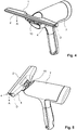
- the suction and suction nozzle mounted on the vacuum cleaner 7 is in FIG. 4 and in FIG. 5 shown. It extends with the intake passage 6 of the suction port 5 into the hand suction device 7, so that the suction gap 4 is in flow communication with the suction unit of the hands suction device 7.
- the pull-off and suction nozzle 2 is pivotally mounted against the force of a return spring, wherein not visible stops limit the pivoting movement.
- the battery that supplies the motor used as the suction unit of the hand suction device 7 is preferably arranged in the handle of the hand suction device 7, since this results in a favorable weight distribution.
- the lower portion of the handle 7 may be formed as a plug-in sleeve for insertion of an extension or telescopic rod.
- the function of the peeling and suction nozzle according to the invention is clear from FIGS. 6 and 7.
- the removal and suction nozzle has a support surface 8, which is formed here in the form of rollers.
- the running surface of the roller thus forms in each case the support surface 8 which, together with the contact surface of the draw-off lip 2, determines the orientation of the removal and suction nozzle relative to the surface 3 to be sucked off. Since the extraction and suction nozzle against the spring force of the spring means 11th is pivotable, regardless of the orientation in which the user presses the device against the surface to be sucked 3, the removal and suction nozzle can take the optimum position.
- the support surface 8 or the roller carrying this surface would abut against the window frame and prevent further driving into the corner by the Abziehlippe 2. This means that the user has to manually pivot the device, which on the one hand can cause it overstretches the Abziehlipp 2 or that the rear boundary of the suction gap 4 lifts from the window surface and on the other hand by the inhomogeneous movement, the suction effect can be affected.
Landscapes
- Nozzles For Electric Vacuum Cleaners (AREA)
- Manipulator (AREA)
Abstract
Description
- Die Erfindung betrifft eine Abzieh- und Saugdüse für ein Handsauggerät nach dem Oberbegriff des Anspruch 1. Ferner betrifft die Erfindung ein Handsauggerät mit einer solchen Abzieh- und Saugdüse.
- Gattungsgemäße Abzieh- und Saugdüsen sind aus der
DE 10 2012 104 102 A1 bekannt. Sie sind zur Befestigung an einem tragbaren, bei bestimmungsgemäßer Benutzung in der Hand eines Benutzers zu haltenden Handsauggerät zum Aufsaugen von Flüssigkeiten oder Flüssigkeits-/Luftgemischen von ebenen Flächen, insbesondere Fensterflächen, Tischen oder ähnlichen, vertikalen, schrägen oder horizontalen Flächen vorgesehen. - Die Abzieh- und Saugdüsen weisen einen Saugkanalanschluss und einen Düsenkörper auf, der zumindest eine Abziehlippe, die entlang der Fläche zum Abziehen von Flüssigkeit in eine Abziehrichtung beweglich ist, und zumindest einen, im Bereich einer Flüssigkeitssammelseite der Abziehlippe angeordneten Ansaugspalt zum Ansaugen der vor der Abziehlippe angesammelten Flüssigkeit in eine mit dem Saugkanalanschluss strömungstechnisch in Verbindung stehende Ansaugkammer aufweist. Der Düsenkörper ist dabei zweiteilig mit einem den Saugkanalanschluss aufweisenden geräteseitigen Stützkörper und einem die Abziehlippe und den Ansaugspalt aufweisenden Saugkörper ausgebildet. Der Stützkörper ist im Abstand zur Abziehlippe und in Abziehrichtung gesehen vor der Abziehlippe angeordnet und bildet mit einer Stützfläche eine Stütze zum Abstützen auf der Fläche. Der Saugkörper ist mit dem Anschlusskörper schwenkbar verbunden und über ein Gelenk um eine Drehachse, die zur Anlagekante der Abziehlippe an der abzusaugenden Fläche parallel verläuft, gegen die Kraft eines Federmittels drehbar, das bei Anliegen der Stütze an der abzusaugenden Fläche die Abziehlippe an die Fläche anstellt.
- Eine Abzieh- und Saugdüse für ein Handsauggerät und ein Handsauggerät sind ferner aus der
US 2011 138 554 A1 bekannt. Diese bekannte Abzieh- und Saugdüse ist Teil eines mobilen Sauggerätes, das als Sauggerät zum Aufsaugen von Flüssigkeiten ausgebildet ist. Eine bevorzugte Anwendung solcher Sauggeräte ist das Abziehen von Fensterflächen nach dem Befeuchten bei gleichzeitigem Aufsaugen der abgezogenen Flüssigkeit. Dieses aus derUS 2011 138 554 A1 bekannte Handsauggerät weist eine schwenkbare Lagerung der Abzieh- und Saugdüse um eine Mittelposition auf, wobei eine Rückstellfeder, die infolge des Anpressdrucks der Abziehlippe gegen die abzusaugende Fläche zunächst gespannt wird und die Abzieh- und Saugdüse nach Wegfall dieses Druckes wieder in die Ausgangsposition zurück stellt, vorgesehen ist. - Grundsätzlich ist die Erfindung allerdings nicht auf Flüssigkeitssauggeräte oder Fensterabzieher beschränkt, sie kann in Verbindung mit allen Formen von Handsauggeräten verwendet werden, wobei bei der bevorzugten Anwendung unter Handsauggerät ein Gerät verstanden wird, das batteriebetrieben ist und so klein ist, dass es mit einer Hand gegriffen und entlang der Fläche geführt werden kann.
- Aus der
WO 2016 029 968 A1 ist eine weitere Abzieh- und Saugdüse bekannt. Auch hier wird die Abzieh- und Saugdüse gegen eine Federkraft verschwenkt, wobei das Gelenk entweder innerhalb der Abzieh- und Saugdüse oder innerhalb des Handsauggerätes angeordnet sein kann. Eine ähnliche Lösung zeigt dieDE 10 2014 001 250 B3 . - Die oben genannten Abzieh- und Saugdüsen und die zugehörigen Handsauggeräte sind zwar gut geeignete, Flüssigkeiten zu sammeln und aufzusaugen, haben aber den Nachteil, dass je nach Orientierung des Handsauggerätes die Abziehlippe mit einem unterschiedlichen Druck und Winkel an die Fläche angestellt wird, was zu unterschiedlichen Abziehergebnissen, insbesondere Streifen- oder Schlierenbildung oder ähnlichen Problemen führen kann. Ferner kann zwar über die schwenkbare Abzieh- und Saugdüse ein definierter Anpressdruck aufgebracht werden, das Absaugen erfolgt allerdings nicht immer optimal, da der Benutzer den optimalen Winkel zum Anstellen der Abziehlippe durch das Ansetzen des Gerätes durch entsprechende Orientierung des Handsauggerätes selbst einstellen muss. Dies ist insbesondere dann nachteilig, wenn Ecken oder Ränder der abzuziehenden Fläche erreicht werden oder wenn das Gerät mit einer Verlängerungsstange benutzt wird, was das Handling des Gerätes aufwändiger und schwieriger macht.
- Aus der
DE 2 143 105 A1 wiederum ist ein mechanisches Abziehgerät bekannt, bei dem ohne Saugfunktion Flüssigkeit von einer Fläche abgezogen werden kann. Dieses Abziehgerät weist eine federbelastete Anlagerolle auf, über die es sich zusätzlich zur Abziehlippe auf der abzusaugenden Fläche abzustützen vermag. Diese Anlagerolle erleichtert die Führung des Abziehgeräts, hat jedoch den Nachteil, dass die Fläche, die zwischen der Anlagerolle und der Abziehlippe liegt, dann, wenn die Anlagerolle am unteren Rand eines Fensters gegen den Rahmen stößt, nur schwierig abgezogen werden kann. - Aufgabe der Erfindung ist es daher, eine Abzieh- und Saugdüse für ein Handsauggerät, bei dem eine optimale Reinigungswirkung durch eine Erleichterung der Anstellung des Gerätes an die abzusaugende Fläche ermöglicht ist. Eine weitere Aufgabe ist es, ein und ein Handsauggerät zu schaffen, dass mit einer solchen Abzieh- und Saugdüse verwendbar ist.
- Diese Aufgabe wird nach der Erfindung hinsichtlich der Abzieh- und Saugdüse durch eine Abzieh- und Saugdüse nach Anspruch 1 gelöst. Hinsichtlich des Handsauggeräts wird diese Aufgabe durch ein Handsauggerät nach Anspruch 11 gelöst.
- Erfindungsgemäß ist die Abzieh- und Saugdüse zweigeteilt: Ein fest mit dem Ansaugstutzen und damit mit dem Handsauggerät verbindbarer Stützkörper und einen hiermit gelenkig verbundenen Saugkörper. An letzterem sind die Abziehlippe und der Ansaugspalt zum Ansaugen des Sauggutes in Form von Flüssigkeiten oder eines Gemisches von Flüssigkeiten mit Schmutz und/oder Luftanteilen vorgesehen. Die Stütze ist dabei relativ zum Saugkanalanschluss fest positioniert, so dass eine über den in der Regel zylindrischen Saugkanal aufgebrachte Druckkraft des Benutzers beim Andrücken der Abzieh- und Saugdüse an die abzuziehende Fläche immer in Richtung Stützfläche gerichtet ist, diese also die Kraft aufnehmen kann. Hierdurch wird der Saukörper von dieser Druckkraft entlastet, wobei der drehbar am Stützkörper gelagerte Saugkörper durch die Federkraft in Richtung der abzuziehenden Fläche angestellt ist, so dass sich die Abziehlippe mit gleichbleibendem Druck - unabhängig von der Druckkraft des Benutzers oder der Orientierung des Geräte relativ zur Fläche, an die Fläche anlegt.
- Durch die neue Abzieh- und Saugdüse für das Handsauggerät und das neue Handsauggerät kann nun der optimale Winkel zum Anstellen der Abziehlippe an die abzusaugende Fläche leicht gefunden werden, da sich eine definierte Lage durch die Stützfläche ergibt. Diese Stützfläche sorgt dafür, dass zusammen mit der Abziehlippe eine doppelte Linienpressung oder eine Kombination einer Linienpressung im Bereich der Abziehlippe mit einer oder mehreren Punkten, an denen sich die Stützfläche auf der Fläche abstützt, vorliegt. Hierdurch wird der Winkel der Abziehlippe relativ zur abzusaugenden Fläche festgelegt und der Benutzer kann das Gerät leicht parallel zur abzusaugenden Fläche verfahren.
- Dadurch, dass nun die Andruckkraft des Benutzers auf das Handsauggerät durch die Stützfläche und bevorzugt auch durch die Drehachse verläuft und gleichzeitig die Abzieh- und Saugdüse um diese Drehachse gegen die Federkraft drehbar gelagert ist, kann sich die Abziehlippe mit dem Druck der Federkraft an die abzuziehende Fläche anlegen. Dies bedeutet, dass unabhängig von der Druckkraft des Benutzers, die im Wesentlichen von der Stützfläche aufgenommen wird, die Abziehlippe immer mit der gleichen Kraft gegen die abzuziehende Fläche gedrückt wird. Damit wird ein reproduzierbares Arbeitsergebnis erreicht und ein zu stark erhöhter Anpressdruck wird vermieden.
- Oft hat der der Benutzer das Problem, dass er in den Ecken oder an Kanten nicht kontinuierlich Abziehen kann, da Ränder des Fensterrahmens oder der Boden die bewegung des Handsauggerätes behindern. Die führt dazu, dass ein Bereich zwischen der Stützfläche und der Abziehlippe nicht mehr optimal abgezogen oder abgesaugt werden kann. Damit dieses Problem vermindert wird, müsste der Benutzer das Gerät bei Erreichen des Fensterrahmens hinten anheben um in den Kanten- oder Eckenbereich hinein zu gelangen. Dies wird nunmehr bei einer bevorzugten Weiterbildung der Erfindung dadurch vereinfacht, dass eine besondere Führungsfläche vorgesehen ist, die automatisch das Gerät anhebt, so dass die Stützfläche von der abzusaugenden Fläche abhebt und über die Kante bzw. die Ecke geführt wird. Der Benutzer kann so das Gerät auf der Führungsfläche weiter abstützen und muss nicht eigenständig den Optimalen Winkel finden, um in die Ecken gelangen zu können. Dies ist insbesondere bei Überkopfarbeit oder bei Geräten interessant, die am Ende einer Teleskop- oder Verlängerungsstange betrieben werden.
- Um die oben genannte Funktion zu realisieren, ist die Führungsfläche auf der, der Abziehlippe gegenüber liegenden Seite der Stützfläche angeordnet. Sie entfernt sich mit zunehmenden Abstand von der Stützfläche immer weiter von der Ebene der abzusaugenden Fläche, so dass eine schiefe Ebene oder eine gerundete Fläche entsteht, die dafür Sorge trägt, dass das Gerät mit dieser Fläche zunächst auf der Kante bzw. Ecke aufsitzt und dann durch das Abgleiten der Führungsfläche auf dem Rand angehoben wird. Der Benutzer stößt also mit dem Gerät nicht gegen eine Kante und muss dann seine Saugbewegung neu ansetzen sondern wird kontinuierlich weitergeführt, so dass das Absaugen der Eckbereiche bzw. Kantenbereiche erleichtert wird.
- Die Stützfläche wird bevorzugt von einem drehbaren Bauteil gebildet, das ein Abrollen der Stützfläche auf der abzusaugenden Fläche ermöglicht. Dies können eine Kugel, eine Walze oder auch mehrere Räder sein. Wichtig ist lediglich, dass die Stützfläche bzw. die Stützflächen im Abstand zur Abziehlippe vorgesehen sind, um eine Ausrichtung des Handsauggerätes zu ermöglichen. Auch die Führungsfläche kann weitgehend beliebig gestaltet werden, sie kann vom Gehäuse der Abzieh- und Saugdüse selbst gebildet sein oder auch von Nocken gebildet sein, die beispielsweise vom unteren Rand des Gehäuses nach unten hervorspringen. Bevorzugt ist die Führungsfläche gerundet, so dass sich eine kontinuierliche, stoßfreie Abhebebewegung infolge der Führung ergibt.
- Nachfolgend werden besonders bevorzugte Ausgestaltungen der Abzieh- und Saugdüse sowie des Handsauggerätes beschrieben, die auch unabhängig von dem Vorsehen der Stützfläche und der Führungsfläche das Gerät vorteilhaft weiterbilden und eine selbstständige Erfindung darstellen können.
- Bevorzugt ist, wie auch schon beim Stand der Technik, die Abzieh- und Saugdüse beweglich gegen ein Federmittel gelagert. Dies hat den Vorteil, dass die Lagerung einen definierten Anpressdruck auch bei kleineren Nickbewegungen des Anwenders sicherstellt. Diese Bewegung der Abzieh- und Saugdüse kann genutzt werden, um das Gerät zu bedienen. Während zum einen der Anpressdruck über einen Drucksensor ermittelt werden kann, so dass infolge dieser Druckerhöhung der Motor in der Leistung erhöht wird oder überhaupt erst eingeschaltet wird, kann auch der Winkel der Abzieh- und Saugdüse relativ zum Handsauggerät erfasst werden und als Schaltungssignal für die Steuerung des Motors des Handsauggerätes genutzt werden.
- Der Saugkörper der Abzieh- und Saugdüse ist über ein Gelenk schwenk- oder drehbar mit dem Stützkörper verbunden, der wiederum seinerseits an dem Saugkanalanschluss, der üblicherweise die Form eines Stutzens aufweist, befestigt iiist bzw. in diesen eingesteckt ist. Der Saugkanal erstreckt sich dabei von dem Handsauggerät durch diesen Saugkanalanschluss in eine Ansaugkammer im Gehäuse des Saugkörpers durch den Stützkörper und bevorzugt auch durch das Gelenk, wobei die Saugkammer im Ansaugkörper wiederum strömungstechnisch mit dem Ansaugspalt, der benachbart zur Ansauglippe vorgesehen ist, verbunden ist.
- Das Gelenk kann ein Kugelgelenk sein, das von dem Strömungskanal durchsetzt ist. Alternativ kann der Strömungskanal auch elastisch ausgebildet sein und zum Beispiel die Form eines Schlauches oder elastischen Rohres aufweisen, während die Abzieh- und Saugdüse über ein separates Gelenk an dem Saugkanalanschluss gelagert sein kann. Auch eine Lagerung der vollständigen Abzieh- und Saugdüse am Handsauggerät über ein Gelenk ist möglich. Das Gelenk wiederum kann eine Kurbelschwinge oder auch ein Lagerbock sein, der zum Beispiel einen hohlzylindrischen Teil der Ansaugkammer beidseitig lagert.
- Die Drehbewegung bzw. Schwenkbewegung der Abzieh- und Saugdüse relativ zum feststehenden Teil des Handsauggerätes ist bevorzugt über Anschläge begrenzt. Ferner kann ein Dämpferelement vorgesehen sein, dass entweder über eine Reibungsdämpfung des Gelenkes oder eine stoßdämpferartige separate Ausgestaltung die Schwenkbewegung der Abzieh- und Saugdüse dämpft. Die Feder wiederum, die die Abzieh- und Saugdüse in die Ausgangsposition zurück stellt, kann eine im Gelenk vorgesehene Feder sein oder auch von einer separaten Feder gebildet sein. Ferner kann die Federwirkung auch über die elastischen Materialeigenschaften der Saugkanalwandung oder sonstiger Bereiche der Abzieh- und Saugdüse realisiert werden.
- Schließlich ist es möglich, dem Benutzer über eine optische Kontrolle anzuzeigen, ob die Stützfläche und die Abziehlippe an der abzusaugenden Fläche anliegen. Hierzu sind entsprechende Sensoren vorgesehen, die zum Beispiel eine Signallampe steuern. Auch ein akustisches Signal, das beispielsweise bei laufendem Motor ohne Kontakt der Stützfläche und der Abziehlippe zu einer Fläche ertönt, ist möglich. Letztlich kann jedes Indikatormittel verwendet werden, dass dem Benutzer den Kontakt der beiden Flächen zur abzusaugenden Fläche bzw. das Fehlen dieses Kontaktes signalisieren kann.
- Eine Steuerung, die das Saugaggregat herunterfährt oder abschaltet, wenn Drucksensoren an der Stützfläche feststellen, dass diese nicht in Anlage an der abzusagenden Fläche ist, kann die Stand-by-Zeit des Gerätes verlängern und Energie sparen. Anstelle der Drucksensoren kann natürlich auch jede andere Sensorik, einschließlich eines Belastungssensors für den Motor des Saugaggregates verwendet werden, der einen Strömungswiderstand im Ansaugkanal oder im Bereich des Saugaggregates unmittelbar oder mittelbar erkennen kann.
- Weitere Merkmale und Vorteile der Erfindung ergeben sich aus der nachfolgenden Beschreibung bevorzugter Ausführungsbeispiele anhand der Zeichnungen.
- In den Zeichnungen zeigen:
- Fig. 1
- ein Ausführungsbeispiel einer erfindungsgemäßen Abzieh- und Saugdüse in einer Seitenansicht,
- Fig. 2
- ein Handsauggerät nach der Erfindung ohne Abzieh- und Saugdüse in einer ersten Ansicht,
- Fig. 3
- das in
Figur 2 dargestellte Handsauggerät aus einer anderen Perspektive, - Fig. 4
- das in den
Figuren 2 und 3 dargestellte Handsauggerät mit montierter Abzieh- und Saugdüse, - Fig. 5
- das Sauggerät aus
Figur 4 aus einer anderen Perspektive, - Fig. 6
- eine schematische Ansicht der Funktionsweise der Abzieh- und Saugdüse nach der Erfindung in einer Schnittansicht und
- Fig. 7
- die Abzieh- und Saugdüse aus
Figur 6 eine schematische Ansicht bei Erreichen des Fensterrahmens. - In
Figur 1 ist eine erfindungsgemäße Abzieh- und Saugdüse dargestellt, die einen Düsenkörper 1 mit einer Abziehlippe 2 und einen rechts daneben angeordneten Gummistreifen aufweist, der zusammen mit der Abziehlippe 2 den Ansaugspalt 4 begrenzt. Der Düsenkörper 1 setzt sich aus einem Stützkörper, der relativ zum Handsauggerät bei montierter Abzieh- und Saugdüse feststehend ist, und einem heran schwenkbar um ein Gelenkt 10 drehbaren Ansaugkörper mit der Abziehlippe 2 zusammen. Über den Ansaugspalt 4 im Absaugkörper kann Flüssigkeit, die sich bei einer Bewegung der Abzieh- und Saugdüse nach rechts vor der Abziehlippe 2 sammelt, in den Ansaugkanal 6 eingesaugt werden. Der Düsenkörper 1 wiederum ist über einen Saugkanalanschluss 5 mit einem hier nicht dargestellten Handsauggerät 7 verbindbar. Bei dieser Ausgestaltung weist das Gehäuse des Düsenkörpers 1 eine innere Ansaugkammer 12 auf, in der der Unterdruck des Saugaggregates des Handsauggerätes 7, das bevorzugt elektromotorisch betrieben ist, bereitgestellt wird. - In den
Figuren 2 und 3 ist ein Handsauggerät 7 dargestellt, dass in Verbindung mit der inFigur 1 dargestellten Abzieh- und Saugdüse verwendet werden kann. Zu erkennen ist der geräteseitige Teil des Gelenkes 10, über den das Handsauggerät 7 gelenkig mit der Abzieh- und Saugdüse verbunden werden kann. Die am Handsauggerät 7 montierte Abzieh- und Saugdüse ist inFigur 4 und inFigur 5 dargestellt. Sie erstreckt sich mit dem Ansaugkanal 6 des Sauganschlusses 5 in das Handsauggerät 7 hinein, so dass der Ansaugspalt 4 in Strömungsverbindung mit dem Saugaggregat des Handsauggerätes 7 steht. - Die Abzieh- und Saugdüse 2 ist schwenkbar gegen die Kraft einer Rückstellfeder gelagert, wobei hier nicht sichtbare Anschläge die Schwenkbewegung begrenzen. Der Akku, der den als Saugaggregat verwendeten Motor des Handsauggerätes 7 versorgt, ist bevorzugt im Handgriff des Handsauggerätes 7 angeordnet, da sich hierdurch eine günstige Gewichtsverteilung ergibt. Der untere Bereich des Handgriffs 7 kann als Steckhülse zum Einstecken einer Verlängerungs- oder Teleskopstange ausgebildet sein.
- Die erfindungsgemäße Funktion der Abzieh- und Saugdüse ergibt sich aus den Figuren 6 und 7 am deutlichsten. Die Abzieh- und Saugdüse weist eine Stützfläche 8 auf, die hier in Form von Rollen ausgebildet ist. Die Lauffläche der Rolle bildet also jeweils die Stützfläche 8, die zusammen mit der Kontaktfläche der Abziehlippe 2 die Orientierung der Abzieh- und Saugdüse relativ zur abzusaugenden Fläche 3 festlegt. Da die Abzieh- und Saugdüse gegen die Federkraft des Federmittels 11 schwenkbar ist, kann unabhängig davon, in welcher Orientierung der Benutzer das Gerät gegen die abzusaugende Fläche 3 drückt, die Abzieh- und Saugdüse die jeweils optimale Position einnehmen.
- Hierdurch ist der Ansaugspalt 4 durch die Abziehlippe 2 und einen darunter angeordneten Gummistreifen geschlossen, so dass sich eine optimale Saugwirkung in die Ansaugkammer 12 der Abzieh- und Saugdüse ergibt. Die Ansaugkammer 12 wiederum ist über den Saugkanalanschluss 5 mit einer hier nicht im Detail dargestellten inneren Ansaugvorrichtung, die mit dem Saugaggregat des Handsauggerätes 7 zusammenwirkt, verbunden.
- Erreicht nun beispielsweise die Abzieh- und Saugdüse beim Fahren entlang eines Fensters den Rand eines Fensterrahmens, so wie es in
Figur 7 dargestellt ist, würde die Stützfläche 8 bzw. die diese Fläche tragende Rolle gegen den Fensterrahmen stoßen und ein weiteres Hineinfahren in die Ecke durch die Abziehlippe 2 verhindern. Dies bedeutet, dass der Benutzer von Hand das Gerät schwenken muss, was einerseits dazu führen kann, dass er die Abziehlippe 2 überdehnt oder dass die hintere Begrenzung des Ansaugspaltes 4 von der Fensterfläche abhebt und zum anderen durch die inhomogene Bewegung die Saugwirkung beeinträchtigt werden kann. - Damit nun im Eckbereich leicht und einfach durch eine homogene Fortsetzung der Bewegung des Handsauggerätes 7 auch dieser Eckbereich ausgesaugt werden kann, ist die Führungsfläche 9 vorgesehen. Diese ist hier in Form eines sich nach unten, glockenartig arbeiteten Randes des Gehäuses des Düsenkörpers 1 ausgebildet. Wie dargestellt, bewirkt dieser nockenartige Bereich, dass sich die Abzieh- und Saugdüse leicht verdreht, so dass die Stützfläche 8 von der abzusaugenden Fläche 3 abhebt und über den Rand des Fensterrahmens geführt wird.
- Dies bewirkt eine effektive Absaugung auch im Eckbereich, so dass der Benutzer mit einer harmonischen Bewegung das Sauggerät bis zum Randbereich des Fensters oder einer sonstigen Fläche führen kann.
-
- 1
- Düsenkörper
- 2
- Abziehlippe
- 3
- Abzusaugende Fläche
- 4
- Ansaugspalt
- 5
- Saugkanalanschluss
- 6
- Ansaugkanal
- 7
- Handsauggerät
- 8
- Stützfläche
- 9
- Führungsfläche
- 10
- Gelenk
- 11
- Federmittel
- 12
- Ansaugkammer
- A
- Abziehrichtung
- D
- Drehachse
Claims (13)
- Abzieh- und Saugdüse zur Befestigung an einem tragbaren, bei bestimmungsgemäßer Benutzung in der Hand eine Benutzers zu haltenden Handsauggerät (7) zum Aufsaugen von Flüssigkeiten oder Flüssigkeits-/Luftgemischen von ebenen Flächen (3), mit einem Saugkanalanschluss (5) und einem einen Düsenkörper (1), der zumindest eine Abziehlippe (2), die entlang der Fläche (3) zum Abziehen von Flüssigkeit in eine Abziehrichtung (A) beweglich ist, und zumindest einen, im Bereich einer Flüssigkeitssammelseite der Abziehlippe (2) angeordneten Ansaugspalt (4) zum Ansaugen der vor der Abziehlippe (2) angesammelten Flüssigkeit in eine mit dem Saugkanalanschluss (5) strömungstechnisch in Verbindung stehende Ansaugkammer (12) aufweist, wobei der Düsenkörper (1) zweiteilig mit einem, den Saugkanalanschluss (5) aufweisenden geräteseitigen Stützkörper und einem, die Abziehlippe (2) und den Ansaugspalt (4) aufweisenden Saugkörper ausgebildet ist und der Stützkörper im Abstand zur Abziehlippe (2) und in Abziehrichtung (A) gesehen vor der Abziehlippe (2) angeordnete Stütze zum Abstützen auf der Fläche (8) aufweist und der Saugkörper über ein Gelenk (10) um eine zur Anlagekante der Abziehlippe (2) an der Fläche (8) parallele Drehachse (D) gegen die Kraft eines, bei Anliegen der Stütze an der Fläche (3) die Abziehlippe (2) an die Fläche (8) anstellenden Federmittels (11) drehbar mit dem Anschlusskörper verbunden ist,
dadurch gekennzeichnet, dass
die Stütze relativ zum Saugkanalanschluss (5) derart ausgebildet ist, dass sie sich bei Andrücken der Abzieh- und Saugdüse an die Fläche (3) mit einer flächigen oder linenartigen Stützfläche (8) im Kontaktbereich an der Fläche (3) abstützt, wobei die Wirkungslinie einer auf den Saugkanalanschluss (5) wirkenden Andruckkraft durch den in der Lage relativ zum Saugkanalanschluss (5) nicht veränderlichen Kontaktbereich der Stütze mit der Fläche (3) verläuft. - Abzieh- und Saugdüse für ein Handsauggerät (7) nach Anspruch 1, dadurch gekennzeichnet, dass die Drehachse (D) derart angeordnet sich, dass die Wirkungslinie durch Drehachse (D) verläuft.
- Abzieh- und Saugdüse für ein Handsauggerät (7) nach Anspruch 1 oder 2,
dadurch gekennzeichnet, dass die Stützfläche (8) von der Lauffläche zumindest einer, drehbar an dem Saugkörper (1) gelagerten, als Rolle oder Walze ausgebildeten Stützrolle gebildet ist. - Abzieh- und Saugdüse für ein Handsauggerät (7) nach Anspruch 1, 2 oder 3, dadurch gekennzeichnet, dass der Saugkörper auf der, der Abziehlippe (2) abgewandten Seite der Stützfläche (8) eine insbesondere von einem gebogenen Führungselement gebildete Führungsfläche (9) aufweist, wobei die Führungsfläche (9) eine in Richtung des Saugkanalanschluss (5) gebogene Fläche ist, die sich mit zunehmenden Abstand von der Stützfläche (8) von der abzusaugenden Fläche (3) entfernt.
- Abzieh- und Saugdüse für ein Handsauggerät (7) nach dem vorhergehenden Anspruch, dadurch gekennzeichnet, dass die Führungsfläche (9) von einem, dem Ansaugspalt (4) abgewandten Bereich des Gehäuses des Düsenkörpers (1) gebildet ist.
- Abzieh- und Saugdüse für ein Handsauggerät (7) nach einem der beiden vorhergehenden Ansprüche, dadurch gekennzeichnet, dass der Düsenkörper (1) wenigstens einen, bevorzugt zwei, im Abstand zueinander angeordnete Führungszapfen aufweist, die zur Bildung der Führungsfläche (9) vom Gehäuse des Düsenkörpers (1) in Abziehrichtung (A) hervorspringen.
- Abzieh- und Saugdüse für ein Handsauggerät (7) nach einem der vorhergehenden Ansprüche, dadurch gekennzeichnet, dass der Saugkanalanschluss (5) von einem, mit dem Handsauggerät (7) verbindbaren an dem Stützkörper fest angeordneten Stutzen gebildet ist, wobei der Stützkörper über das Gelenk (10) mit dem Saugkörper des Düsenkörpers (1) verbunden ist und sich ein Strömungskanal von dem Ansaugspalt (4) durch das Gelenk (10) und den Stutzen erstreckt.
- Abzieh- und Saugdüse für ein Handsauggerät (7) nach einem der vorhergehenden Ansprüche, dadurch gekennzeichnet, dass die Abziehlippe (2) um eine zur abzusaugenden Fläche (3) rechtwinklige Achse mittelbar oder unmittelbar relativ zum Saugkanalanschluss (5) drehbar gelagert ist.
- Abzieh- und Saugdüse für ein Handsauggerät (7) nach einem der vorhergehenden Ansprüche, dadurch gekennzeichnet, dass das Gelenk (10) als Kugelgelenk ausgebildet oder von einem elastischen Gehäusebereich der Abzieh- und Saugdüse gebildet ist.
- Abzieh- und Saugdüse für ein Handsauggerät (7) nach einem der Ansprüche 1 bis 8, dadurch gekennzeichnet, dass das Gelenk (10) als Kurbelschwinge ausgebildet oder von einem Lagerbock gebildet ist, an dem zwei Enden eines hohlzylindrisch ausgebildeten Bereichs einer im Gehäuse ausgebildeten Ansaugkammer (12) drehbar gelagert sind.
- Handsauggerät (7) mit einem Saugaggregat, einem Sauggutbehälter, einem Ansaugkanal (6) und einer Abzieh- und Saugdüse zum Aufsaugen von Sauggut in Form von Flüssigkeiten oder Flüssigkeits-/Luftgemischen in den Sauggutbehälter,
dadurch gekennzeichnet, dass
die Abzieh- und Saugdüse eine Abzieh- und Saugdüse nach einem der Ansprüche 1 bis 10 ist. - Handsauggerät (7) nach dem vorhergehenden Anspruch, dadurch gekennzeichnet, dass die Abzieh- und Saugdüse (1) zumindest einen Leistungsschalter aufweist, wobei das Handsauggerät (7) eine Steuerung aufweist, die mit dem Leistungsschalter zusammenwirkt, so dass über den Leistungsschalter die Steuerung derart schaltbar ist, dass über den Leistungsschalter das Saugaggregat in seiner Leistung herunter- bzw. heraufgefahren werden kann oder aus- bzw. eingeschaltet werden kann, wobei über einen oder mehrere Drucksensoren die Anlage der Stützfläche (8) und/oder der Abziehlippe (2) an der abzusaugenden Fläche (3) erfassbar ist und die Steuerung bei fehlendem Druck auf die Drucksensoren das Saugaggregat selbsttätig heruntergefahren oder abgeschaltet wird.
- Handsauggerät (7) nach dem vorhergehenden Anspruch, dadurch gekennzeichnet, dass das Handsauggerät (7) optische und/oder akustische Indikatormittel aufweist, über die ein Abheben der Stützfläche (8) und/oder der Abziehlippe (2) von der abzusaugenden Fläche (3) dem Benutzer anzeigbar ist, wobei die Steuerung bei entsprechendem Signal der Drucksensoren die Indikatormittel selbstständig zu aktivieren vermag.
Applications Claiming Priority (1)
| Application Number | Priority Date | Filing Date | Title |
|---|---|---|---|
| DE102017105176.7A DE102017105176A1 (de) | 2017-03-10 | 2017-03-10 | Saugdüse für ein Handsauggerät und Handsauggerät |
Publications (2)
| Publication Number | Publication Date |
|---|---|
| EP3372135A1 true EP3372135A1 (de) | 2018-09-12 |
| EP3372135B1 EP3372135B1 (de) | 2021-09-29 |
Family
ID=61563199
Family Applications (1)
| Application Number | Title | Priority Date | Filing Date |
|---|---|---|---|
| EP18159772.5A Active EP3372135B1 (de) | 2017-03-10 | 2018-03-02 | Saugdüse für ein handsauggerät und handsauggerät |
Country Status (2)
| Country | Link |
|---|---|
| EP (1) | EP3372135B1 (de) |
| DE (1) | DE102017105176A1 (de) |
Cited By (2)
| Publication number | Priority date | Publication date | Assignee | Title |
|---|---|---|---|---|
| CN116763196A (zh) * | 2022-03-11 | 2023-09-19 | 追觅创新科技(苏州)有限公司 | 清洁设备、清洁设备的控制方法及存储介质 |
| CN119426287A (zh) * | 2025-01-10 | 2025-02-14 | 石狮市鸿峰环保生物工程有限公司 | 一种多角度调节的手持式声波吹灰器 |
Families Citing this family (1)
| Publication number | Priority date | Publication date | Assignee | Title |
|---|---|---|---|---|
| DE102022102595A1 (de) | 2022-02-03 | 2023-08-03 | Brandivision Gmbh | Körper für einen Abzieher oder Wischer, Abzieher und Wischer sowie Verfahren zum Abziehen oder Wischen |
Citations (5)
| Publication number | Priority date | Publication date | Assignee | Title |
|---|---|---|---|---|
| US20120266923A1 (en) * | 2011-04-21 | 2012-10-25 | Mark John Steinhardt | Device Having a Renewable Blade Surface For Treating a Target Surface |
| DE102012104102A1 (de) * | 2011-11-17 | 2013-05-23 | Vorwerk & Co. Interholding Gmbh | Feuchtreinigungsvorrichtung |
| WO2014009672A1 (fr) * | 2012-07-12 | 2014-01-16 | Ecodrop | Appareil de nettoyage de parois planes |
| WO2016029966A1 (de) * | 2014-08-29 | 2016-03-03 | Alfred Kärcher Gmbh & Co. Kg | Saugdüse und hartflächenabsauggerät |
| EP2992799A1 (de) * | 2014-09-05 | 2016-03-09 | Leifheit Ag | Tragbares Sauggerät mit auswechselbarer Saugdüse |
Family Cites Families (4)
| Publication number | Priority date | Publication date | Assignee | Title |
|---|---|---|---|---|
| DE102011050697A1 (de) | 2011-05-27 | 2012-11-29 | Leifheit Ag | Flüssigkeitssaugvorrichtung zum Abziehen und Aufsaugen von Flüssigkeiten |
| US9126323B2 (en) | 2011-08-22 | 2015-09-08 | The Procter & Gamble Company | Device for treating a target surface and having an ergonomically pivoting handle |
| DE102014001250C5 (de) | 2014-02-03 | 2021-07-29 | Carl Freudenberg Kg | Fensterwischer |
| EP3185743B1 (de) | 2014-08-29 | 2019-11-13 | Alfred Kärcher SE & Co. KG | Saugdüse und hartflächenabsauggerät |
-
2017
- 2017-03-10 DE DE102017105176.7A patent/DE102017105176A1/de not_active Withdrawn
-
2018
- 2018-03-02 EP EP18159772.5A patent/EP3372135B1/de active Active
Patent Citations (5)
| Publication number | Priority date | Publication date | Assignee | Title |
|---|---|---|---|---|
| US20120266923A1 (en) * | 2011-04-21 | 2012-10-25 | Mark John Steinhardt | Device Having a Renewable Blade Surface For Treating a Target Surface |
| DE102012104102A1 (de) * | 2011-11-17 | 2013-05-23 | Vorwerk & Co. Interholding Gmbh | Feuchtreinigungsvorrichtung |
| WO2014009672A1 (fr) * | 2012-07-12 | 2014-01-16 | Ecodrop | Appareil de nettoyage de parois planes |
| WO2016029966A1 (de) * | 2014-08-29 | 2016-03-03 | Alfred Kärcher Gmbh & Co. Kg | Saugdüse und hartflächenabsauggerät |
| EP2992799A1 (de) * | 2014-09-05 | 2016-03-09 | Leifheit Ag | Tragbares Sauggerät mit auswechselbarer Saugdüse |
Cited By (3)
| Publication number | Priority date | Publication date | Assignee | Title |
|---|---|---|---|---|
| CN116763196A (zh) * | 2022-03-11 | 2023-09-19 | 追觅创新科技(苏州)有限公司 | 清洁设备、清洁设备的控制方法及存储介质 |
| CN119426287A (zh) * | 2025-01-10 | 2025-02-14 | 石狮市鸿峰环保生物工程有限公司 | 一种多角度调节的手持式声波吹灰器 |
| CN119426287B (zh) * | 2025-01-10 | 2025-04-22 | 石狮市鸿峰环保生物工程有限公司 | 一种多角度调节的手持式声波吹灰器 |
Also Published As
| Publication number | Publication date |
|---|---|
| EP3372135B1 (de) | 2021-09-29 |
| DE102017105176A1 (de) | 2018-09-13 |
Similar Documents
| Publication | Publication Date | Title |
|---|---|---|
| EP0162358B1 (de) | Muttermilchabsaugvorrichtung | |
| EP3102081B1 (de) | Fensterwischer | |
| EP2362152B1 (de) | Dunstabzugshaube mit einem verschiebbar geführten Wrasenschirm | |
| DE102010043515B4 (de) | Saugdüsenanordnung und Bodenstaubsauger | |
| EP3372135B1 (de) | Saugdüse für ein handsauggerät und handsauggerät | |
| DE202011051495U1 (de) | Düse für Staubsauger mit innenliegendem Ansaugkanal | |
| EP3025626A1 (de) | Bodendüse für ein bodenpflegegerät und verfahren zum herstellen einer bodendüse für ein bodenpflegegerät | |
| EP2587977B1 (de) | Staubsaugerdüse | |
| DE102012104102A1 (de) | Feuchtreinigungsvorrichtung | |
| DE202008010345U1 (de) | Vorrichtung zur Unterwasserreinigung von Oberflächen | |
| EP1595485A1 (de) | Bodendüse für Staubsauger | |
| DE102021119016A1 (de) | Bodenreinigungsvorrichtung | |
| EP2783615B1 (de) | Vorrichtung zur Reinigung glatter Oberflächen | |
| EP3048943B1 (de) | Saugdüsenvorrichtung für ein reinigungsgerät und reinigungsgerät | |
| EP3133972B1 (de) | Saugdüse und hartflächenreinigungsgerät | |
| EP1838198B1 (de) | Feuchtwischer mit einem flächigen halter | |
| DE102007026566B4 (de) | Reinigungswagen | |
| EP2397058A2 (de) | Reinigungsgerät mit Flächenreinigungselement | |
| EP3106566B1 (de) | Saugfussanordnung für eine bodenreinigungsmaschine | |
| EP3185743B1 (de) | Saugdüse und hartflächenabsauggerät | |
| EP3013205A1 (de) | Fahrbare aufsitz-bodenreinigungsmaschine und verfahren zur positionierung eines saugbalkens einer fahrbaren aufsitz-bodenreinigungsmaschine | |
| DE102011055445A1 (de) | Reinigungsvorrichtung mit einem Saugkanal | |
| EP3345523A1 (de) | Bodendüse für staubsauger und staubsauger | |
| WO2017041837A1 (de) | Bodendüse | |
| EP2177144A1 (de) | Staubsauger |
Legal Events
| Date | Code | Title | Description |
|---|---|---|---|
| PUAI | Public reference made under article 153(3) epc to a published international application that has entered the european phase |
Free format text: ORIGINAL CODE: 0009012 |
|
| STAA | Information on the status of an ep patent application or granted ep patent |
Free format text: STATUS: THE APPLICATION HAS BEEN PUBLISHED |
|
| AK | Designated contracting states |
Kind code of ref document: A1 Designated state(s): AL AT BE BG CH CY CZ DE DK EE ES FI FR GB GR HR HU IE IS IT LI LT LU LV MC MK MT NL NO PL PT RO RS SE SI SK SM TR |
|
| AX | Request for extension of the european patent |
Extension state: BA ME |
|
| STAA | Information on the status of an ep patent application or granted ep patent |
Free format text: STATUS: REQUEST FOR EXAMINATION WAS MADE |
|
| 17P | Request for examination filed |
Effective date: 20190308 |
|
| RBV | Designated contracting states (corrected) |
Designated state(s): AL AT BE BG CH CY CZ DE DK EE ES FI FR GB GR HR HU IE IS IT LI LT LU LV MC MK MT NL NO PL PT RO RS SE SI SK SM TR |
|
| GRAP | Despatch of communication of intention to grant a patent |
Free format text: ORIGINAL CODE: EPIDOSNIGR1 |
|
| STAA | Information on the status of an ep patent application or granted ep patent |
Free format text: STATUS: GRANT OF PATENT IS INTENDED |
|
| GRAS | Grant fee paid |
Free format text: ORIGINAL CODE: EPIDOSNIGR3 |
|
| GRAA | (expected) grant |
Free format text: ORIGINAL CODE: 0009210 |
|
| STAA | Information on the status of an ep patent application or granted ep patent |
Free format text: STATUS: THE PATENT HAS BEEN GRANTED |
|
| RIC1 | Information provided on ipc code assigned before grant |
Ipc: A47L 1/05 20060101AFI20210726BHEP |
|
| INTG | Intention to grant announced |
Effective date: 20210813 |
|
| AK | Designated contracting states |
Kind code of ref document: B1 Designated state(s): AL AT BE BG CH CY CZ DE DK EE ES FI FR GB GR HR HU IE IS IT LI LT LU LV MC MK MT NL NO PL PT RO RS SE SI SK SM TR |
|
| REG | Reference to a national code |
Ref country code: GB Ref legal event code: FG4D Free format text: NOT ENGLISH |
|
| REG | Reference to a national code |
Ref country code: CH Ref legal event code: EP Ref country code: AT Ref legal event code: REF Ref document number: 1433488 Country of ref document: AT Kind code of ref document: T Effective date: 20211015 |
|
| REG | Reference to a national code |
Ref country code: DE Ref legal event code: R096 Ref document number: 502018007219 Country of ref document: DE |
|
| REG | Reference to a national code |
Ref country code: IE Ref legal event code: FG4D Free format text: LANGUAGE OF EP DOCUMENT: GERMAN |
|
| REG | Reference to a national code |
Ref country code: LT Ref legal event code: MG9D |
|
| PG25 | Lapsed in a contracting state [announced via postgrant information from national office to epo] |
Ref country code: NO Free format text: LAPSE BECAUSE OF FAILURE TO SUBMIT A TRANSLATION OF THE DESCRIPTION OR TO PAY THE FEE WITHIN THE PRESCRIBED TIME-LIMIT Effective date: 20211229 Ref country code: LT Free format text: LAPSE BECAUSE OF FAILURE TO SUBMIT A TRANSLATION OF THE DESCRIPTION OR TO PAY THE FEE WITHIN THE PRESCRIBED TIME-LIMIT Effective date: 20210929 Ref country code: BG Free format text: LAPSE BECAUSE OF FAILURE TO SUBMIT A TRANSLATION OF THE DESCRIPTION OR TO PAY THE FEE WITHIN THE PRESCRIBED TIME-LIMIT Effective date: 20211229 Ref country code: RS Free format text: LAPSE BECAUSE OF FAILURE TO SUBMIT A TRANSLATION OF THE DESCRIPTION OR TO PAY THE FEE WITHIN THE PRESCRIBED TIME-LIMIT Effective date: 20210929 Ref country code: SE Free format text: LAPSE BECAUSE OF FAILURE TO SUBMIT A TRANSLATION OF THE DESCRIPTION OR TO PAY THE FEE WITHIN THE PRESCRIBED TIME-LIMIT Effective date: 20210929 Ref country code: FI Free format text: LAPSE BECAUSE OF FAILURE TO SUBMIT A TRANSLATION OF THE DESCRIPTION OR TO PAY THE FEE WITHIN THE PRESCRIBED TIME-LIMIT Effective date: 20210929 Ref country code: HR Free format text: LAPSE BECAUSE OF FAILURE TO SUBMIT A TRANSLATION OF THE DESCRIPTION OR TO PAY THE FEE WITHIN THE PRESCRIBED TIME-LIMIT Effective date: 20210929 |
|
| REG | Reference to a national code |
Ref country code: NL Ref legal event code: MP Effective date: 20210929 |
|
| PG25 | Lapsed in a contracting state [announced via postgrant information from national office to epo] |
Ref country code: LV Free format text: LAPSE BECAUSE OF FAILURE TO SUBMIT A TRANSLATION OF THE DESCRIPTION OR TO PAY THE FEE WITHIN THE PRESCRIBED TIME-LIMIT Effective date: 20210929 Ref country code: GR Free format text: LAPSE BECAUSE OF FAILURE TO SUBMIT A TRANSLATION OF THE DESCRIPTION OR TO PAY THE FEE WITHIN THE PRESCRIBED TIME-LIMIT Effective date: 20211230 |
|
| PG25 | Lapsed in a contracting state [announced via postgrant information from national office to epo] |
Ref country code: IS Free format text: LAPSE BECAUSE OF FAILURE TO SUBMIT A TRANSLATION OF THE DESCRIPTION OR TO PAY THE FEE WITHIN THE PRESCRIBED TIME-LIMIT Effective date: 20220129 Ref country code: SK Free format text: LAPSE BECAUSE OF FAILURE TO SUBMIT A TRANSLATION OF THE DESCRIPTION OR TO PAY THE FEE WITHIN THE PRESCRIBED TIME-LIMIT Effective date: 20210929 Ref country code: RO Free format text: LAPSE BECAUSE OF FAILURE TO SUBMIT A TRANSLATION OF THE DESCRIPTION OR TO PAY THE FEE WITHIN THE PRESCRIBED TIME-LIMIT Effective date: 20210929 Ref country code: PT Free format text: LAPSE BECAUSE OF FAILURE TO SUBMIT A TRANSLATION OF THE DESCRIPTION OR TO PAY THE FEE WITHIN THE PRESCRIBED TIME-LIMIT Effective date: 20220131 Ref country code: PL Free format text: LAPSE BECAUSE OF FAILURE TO SUBMIT A TRANSLATION OF THE DESCRIPTION OR TO PAY THE FEE WITHIN THE PRESCRIBED TIME-LIMIT Effective date: 20210929 Ref country code: NL Free format text: LAPSE BECAUSE OF FAILURE TO SUBMIT A TRANSLATION OF THE DESCRIPTION OR TO PAY THE FEE WITHIN THE PRESCRIBED TIME-LIMIT Effective date: 20210929 Ref country code: ES Free format text: LAPSE BECAUSE OF FAILURE TO SUBMIT A TRANSLATION OF THE DESCRIPTION OR TO PAY THE FEE WITHIN THE PRESCRIBED TIME-LIMIT Effective date: 20210929 Ref country code: EE Free format text: LAPSE BECAUSE OF FAILURE TO SUBMIT A TRANSLATION OF THE DESCRIPTION OR TO PAY THE FEE WITHIN THE PRESCRIBED TIME-LIMIT Effective date: 20210929 Ref country code: AL Free format text: LAPSE BECAUSE OF FAILURE TO SUBMIT A TRANSLATION OF THE DESCRIPTION OR TO PAY THE FEE WITHIN THE PRESCRIBED TIME-LIMIT Effective date: 20210929 |
|
| REG | Reference to a national code |
Ref country code: DE Ref legal event code: R097 Ref document number: 502018007219 Country of ref document: DE |
|
| PG25 | Lapsed in a contracting state [announced via postgrant information from national office to epo] |
Ref country code: DK Free format text: LAPSE BECAUSE OF FAILURE TO SUBMIT A TRANSLATION OF THE DESCRIPTION OR TO PAY THE FEE WITHIN THE PRESCRIBED TIME-LIMIT Effective date: 20210929 |
|
| PLBE | No opposition filed within time limit |
Free format text: ORIGINAL CODE: 0009261 |
|
| STAA | Information on the status of an ep patent application or granted ep patent |
Free format text: STATUS: NO OPPOSITION FILED WITHIN TIME LIMIT |
|
| 26N | No opposition filed |
Effective date: 20220630 |
|
| PG25 | Lapsed in a contracting state [announced via postgrant information from national office to epo] |
Ref country code: MC Free format text: LAPSE BECAUSE OF FAILURE TO SUBMIT A TRANSLATION OF THE DESCRIPTION OR TO PAY THE FEE WITHIN THE PRESCRIBED TIME-LIMIT Effective date: 20210929 |
|
| REG | Reference to a national code |
Ref country code: CH Ref legal event code: PL |
|
| GBPC | Gb: european patent ceased through non-payment of renewal fee |
Effective date: 20220302 |
|
| PG25 | Lapsed in a contracting state [announced via postgrant information from national office to epo] |
Ref country code: SI Free format text: LAPSE BECAUSE OF FAILURE TO SUBMIT A TRANSLATION OF THE DESCRIPTION OR TO PAY THE FEE WITHIN THE PRESCRIBED TIME-LIMIT Effective date: 20210929 |
|
| REG | Reference to a national code |
Ref country code: BE Ref legal event code: MM Effective date: 20220331 |
|
| PG25 | Lapsed in a contracting state [announced via postgrant information from national office to epo] |
Ref country code: LU Free format text: LAPSE BECAUSE OF NON-PAYMENT OF DUE FEES Effective date: 20220302 Ref country code: LI Free format text: LAPSE BECAUSE OF NON-PAYMENT OF DUE FEES Effective date: 20220331 Ref country code: IT Free format text: LAPSE BECAUSE OF FAILURE TO SUBMIT A TRANSLATION OF THE DESCRIPTION OR TO PAY THE FEE WITHIN THE PRESCRIBED TIME-LIMIT Effective date: 20210929 Ref country code: IE Free format text: LAPSE BECAUSE OF NON-PAYMENT OF DUE FEES Effective date: 20220302 Ref country code: GB Free format text: LAPSE BECAUSE OF NON-PAYMENT OF DUE FEES Effective date: 20220302 Ref country code: FR Free format text: LAPSE BECAUSE OF NON-PAYMENT OF DUE FEES Effective date: 20220331 Ref country code: CH Free format text: LAPSE BECAUSE OF NON-PAYMENT OF DUE FEES Effective date: 20220331 |
|
| PG25 | Lapsed in a contracting state [announced via postgrant information from national office to epo] |
Ref country code: BE Free format text: LAPSE BECAUSE OF NON-PAYMENT OF DUE FEES Effective date: 20220331 |
|
| PG25 | Lapsed in a contracting state [announced via postgrant information from national office to epo] |
Ref country code: HU Free format text: LAPSE BECAUSE OF FAILURE TO SUBMIT A TRANSLATION OF THE DESCRIPTION OR TO PAY THE FEE WITHIN THE PRESCRIBED TIME-LIMIT; INVALID AB INITIO Effective date: 20180302 |
|
| PG25 | Lapsed in a contracting state [announced via postgrant information from national office to epo] |
Ref country code: SM Free format text: LAPSE BECAUSE OF FAILURE TO SUBMIT A TRANSLATION OF THE DESCRIPTION OR TO PAY THE FEE WITHIN THE PRESCRIBED TIME-LIMIT Effective date: 20210929 Ref country code: MK Free format text: LAPSE BECAUSE OF FAILURE TO SUBMIT A TRANSLATION OF THE DESCRIPTION OR TO PAY THE FEE WITHIN THE PRESCRIBED TIME-LIMIT Effective date: 20210929 Ref country code: CY Free format text: LAPSE BECAUSE OF FAILURE TO SUBMIT A TRANSLATION OF THE DESCRIPTION OR TO PAY THE FEE WITHIN THE PRESCRIBED TIME-LIMIT Effective date: 20210929 |
|
| REG | Reference to a national code |
Ref country code: AT Ref legal event code: MM01 Ref document number: 1433488 Country of ref document: AT Kind code of ref document: T Effective date: 20230302 |
|
| PG25 | Lapsed in a contracting state [announced via postgrant information from national office to epo] |
Ref country code: AT Free format text: LAPSE BECAUSE OF NON-PAYMENT OF DUE FEES Effective date: 20230302 |
|
| PG25 | Lapsed in a contracting state [announced via postgrant information from national office to epo] |
Ref country code: AT Free format text: LAPSE BECAUSE OF NON-PAYMENT OF DUE FEES Effective date: 20230302 |
|
| PG25 | Lapsed in a contracting state [announced via postgrant information from national office to epo] |
Ref country code: MT Free format text: LAPSE BECAUSE OF FAILURE TO SUBMIT A TRANSLATION OF THE DESCRIPTION OR TO PAY THE FEE WITHIN THE PRESCRIBED TIME-LIMIT Effective date: 20210929 |
|
| REG | Reference to a national code |
Ref country code: DE Ref legal event code: R082 Ref document number: 502018007219 Country of ref document: DE Representative=s name: KBN IP PATENTANWAELTE PARTNERSCHAFT MBB, DE |
|
| PG25 | Lapsed in a contracting state [announced via postgrant information from national office to epo] |
Ref country code: TR Free format text: LAPSE BECAUSE OF FAILURE TO SUBMIT A TRANSLATION OF THE DESCRIPTION OR TO PAY THE FEE WITHIN THE PRESCRIBED TIME-LIMIT Effective date: 20210929 |
|
| PGFP | Annual fee paid to national office [announced via postgrant information from national office to epo] |
Ref country code: DE Payment date: 20260120 Year of fee payment: 9 |
|
| PGFP | Annual fee paid to national office [announced via postgrant information from national office to epo] |
Ref country code: AT Payment date: 20260410 Year of fee payment: 5 |
|
| PGFP | Annual fee paid to national office [announced via postgrant information from national office to epo] |
Ref country code: CZ Payment date: 20260213 Year of fee payment: 9 |