EP3371583B1 - Akustische resonatorvorrichtungen und herstellungsverfahren mit bereitstellung von dichtigkeit und oberflächenfunktionalisierung - Google Patents
Akustische resonatorvorrichtungen und herstellungsverfahren mit bereitstellung von dichtigkeit und oberflächenfunktionalisierung Download PDFInfo
- Publication number
- EP3371583B1 EP3371583B1 EP16794124.4A EP16794124A EP3371583B1 EP 3371583 B1 EP3371583 B1 EP 3371583B1 EP 16794124 A EP16794124 A EP 16794124A EP 3371583 B1 EP3371583 B1 EP 3371583B1
- Authority
- EP
- European Patent Office
- Prior art keywords
- layer
- interface layer
- over
- hermeticity
- acoustic wave
- Prior art date
- Legal status (The legal status is an assumption and is not a legal conclusion. Google has not performed a legal analysis and makes no representation as to the accuracy of the status listed.)
- Active
Links
Images


Classifications
-
- G—PHYSICS
- G01—MEASURING; TESTING
- G01N—INVESTIGATING OR ANALYSING MATERIALS BY DETERMINING THEIR CHEMICAL OR PHYSICAL PROPERTIES
- G01N29/00—Investigating or analysing materials by the use of ultrasonic, sonic or infrasonic waves; Visualisation of the interior of objects by transmitting ultrasonic or sonic waves through the object
- G01N29/02—Analysing fluids
- G01N29/022—Fluid sensors based on microsensors, e.g. quartz crystal-microbalance [QCM], surface acoustic wave [SAW] devices, tuning forks, cantilevers, flexural plate wave [FPW] devices
-
- G—PHYSICS
- G01—MEASURING; TESTING
- G01N—INVESTIGATING OR ANALYSING MATERIALS BY DETERMINING THEIR CHEMICAL OR PHYSICAL PROPERTIES
- G01N29/00—Investigating or analysing materials by the use of ultrasonic, sonic or infrasonic waves; Visualisation of the interior of objects by transmitting ultrasonic or sonic waves through the object
- G01N29/22—Details, e.g. general constructional or apparatus details
- G01N29/222—Constructional or flow details for analysing fluids
-
- G—PHYSICS
- G01—MEASURING; TESTING
- G01N—INVESTIGATING OR ANALYSING MATERIALS BY DETERMINING THEIR CHEMICAL OR PHYSICAL PROPERTIES
- G01N29/00—Investigating or analysing materials by the use of ultrasonic, sonic or infrasonic waves; Visualisation of the interior of objects by transmitting ultrasonic or sonic waves through the object
- G01N29/22—Details, e.g. general constructional or apparatus details
- G01N29/24—Probes
- G01N29/2437—Piezoelectric probes
-
- G—PHYSICS
- G01—MEASURING; TESTING
- G01N—INVESTIGATING OR ANALYSING MATERIALS BY DETERMINING THEIR CHEMICAL OR PHYSICAL PROPERTIES
- G01N2291/00—Indexing codes associated with group G01N29/00
- G01N2291/01—Indexing codes associated with the measuring variable
- G01N2291/012—Phase angle
-
- G—PHYSICS
- G01—MEASURING; TESTING
- G01N—INVESTIGATING OR ANALYSING MATERIALS BY DETERMINING THEIR CHEMICAL OR PHYSICAL PROPERTIES
- G01N2291/00—Indexing codes associated with group G01N29/00
- G01N2291/01—Indexing codes associated with the measuring variable
- G01N2291/014—Resonance or resonant frequency
-
- G—PHYSICS
- G01—MEASURING; TESTING
- G01N—INVESTIGATING OR ANALYSING MATERIALS BY DETERMINING THEIR CHEMICAL OR PHYSICAL PROPERTIES
- G01N2291/00—Indexing codes associated with group G01N29/00
- G01N2291/01—Indexing codes associated with the measuring variable
- G01N2291/015—Attenuation, scattering
-
- G—PHYSICS
- G01—MEASURING; TESTING
- G01N—INVESTIGATING OR ANALYSING MATERIALS BY DETERMINING THEIR CHEMICAL OR PHYSICAL PROPERTIES
- G01N2291/00—Indexing codes associated with group G01N29/00
- G01N2291/02—Indexing codes associated with the analysed material
- G01N2291/025—Change of phase or condition
- G01N2291/0255—(Bio)chemical reactions, e.g. on biosensors
-
- G—PHYSICS
- G01—MEASURING; TESTING
- G01N—INVESTIGATING OR ANALYSING MATERIALS BY DETERMINING THEIR CHEMICAL OR PHYSICAL PROPERTIES
- G01N2291/00—Indexing codes associated with group G01N29/00
- G01N2291/02—Indexing codes associated with the analysed material
- G01N2291/025—Change of phase or condition
- G01N2291/0256—Adsorption, desorption, surface mass change, e.g. on biosensors
-
- G—PHYSICS
- G01—MEASURING; TESTING
- G01N—INVESTIGATING OR ANALYSING MATERIALS BY DETERMINING THEIR CHEMICAL OR PHYSICAL PROPERTIES
- G01N2291/00—Indexing codes associated with group G01N29/00
- G01N2291/04—Wave modes and trajectories
- G01N2291/042—Wave modes
- G01N2291/0426—Bulk waves, e.g. quartz crystal microbalance, torsional waves
-
- H—ELECTRICITY
- H03—ELECTRONIC CIRCUITRY
- H03H—IMPEDANCE NETWORKS, e.g. RESONANT CIRCUITS; RESONATORS
- H03H9/00—Networks comprising electromechanical or electro-acoustic elements; Electromechanical resonators
- H03H9/15—Constructional features of resonators consisting of piezoelectric or electrostrictive material
- H03H9/17—Constructional features of resonators consisting of piezoelectric or electrostrictive material having a single resonator
- H03H9/171—Constructional features of resonators consisting of piezoelectric or electrostrictive material having a single resonator implemented with thin-film techniques, i.e. of the film bulk acoustic resonator [FBAR] type
- H03H9/172—Means for mounting on a substrate, i.e. means constituting the material interface confining the waves to a volume
- H03H9/175—Acoustic mirrors
Definitions
- the present disclosure relates to acoustic resonator devices, including acoustic wave sensors and microfluidic devices suitable for biosensing or biochemical sensing applications.
- a biosensor is an analytical device including a biological element and a transducer that converts a biological response into an electrical signal.
- Certain biosensors involve a selective biochemical reaction between a specific binding material (e.g., an antibody, a receptor, a ligand, etc.) and a target species (e.g., molecule, protein, DNA, virus, bacteria, etc.), and the product of this highly specific reaction is converted into a measurable quantity by a transducer.
- Other sensors may utilize a non-specific binding material capable of binding multiple types or classes of molecules or other moieties that may be present in a sample, such as may be useful in chemical sensing applications.
- the term "functionalization material" may be used herein to generally relate to both specific and non-specific binding materials.
- Transduction methods may be based on various principles, such as electrochemical, optical, electrical, acoustic, and so on.
- electrochemical, optical, electrical, acoustic, and so on offers a number of potential advantages, such as being real time, label-free, and low cost, as well as exhibiting high sensitivity.
- An acoustic wave device employs an acoustic wave that propagates through or on the surface of a piezoelectric material, whereby any changes to the characteristics of the propagation path affect the velocity and/or amplitude of the wave.
- Presence of functionalization material embodied in a specific binding material along an active region of an acoustic wave device permits a specific analyte to be bound to the specific binding material, thereby altering the mass being vibrated by the acoustic wave and altering the wave propagation characteristics (e.g., velocity, thereby altering resonance frequency). Changes in velocity can be monitored by measuring the frequency, magnitude, or phase characteristics of the sensor, and can be correlated to a physical quantity being measured.
- an acoustic wave may embody either a bulk acoustic wave (BAW) propagating through the interior of a substrate, or a surface acoustic wave (SAW) propagating on the surface of the substrate.
- BAW bulk acoustic wave
- SAW surface acoustic wave
- SAW devices involve transduction of acoustic waves (commonly including two-dimensional Rayleigh waves) utilizing interdigital transducers along the surface of a piezoelectric material, with the waves being confined to a penetration depth of about one wavelength.
- three wave modes can propagate, namely, one longitudinal mode (embodying longitudinal waves, also called compressional/extensional waves), and two shear modes (embodying shear waves, also called transverse waves), with longitudinal and shear modes respectively identifying vibrations where particle motion is parallel to or perpendicular to the direction of wave propagation.
- the longitudinal mode is characterized by compression and elongation in the direction of the propagation, whereas the shear modes consist of motion perpendicular to the direction of propagation with no local change of volume. Longitudinal and shear modes propagate at different velocities. In practice, these modes are not necessarily pure modes as the particle vibration, or polarization, is neither purely parallel nor purely perpendicular to the propagation direction.
- the propagation characteristics of the respective modes depend on the material properties and propagation direction respective to the crystal axis orientations.
- the ability to create shear displacements is beneficial for operation of acoustic wave devices with fluids (e.g., liquids) because shear waves do not impart significant energy into fluids.
- Certain piezoelectric thin films are capable of exciting both longitudinal and shear mode resonance, such as hexagonal crystal structure piezoelectric materials including (but not limited to) aluminum nitride [AIN] and zinc oxide [ZnO].
- hexagonal crystal structure piezoelectric materials including (but not limited to) aluminum nitride [AIN] and zinc oxide [ZnO].
- AIN aluminum nitride
- ZnO zinc oxide
- a polarization axis in a piezoelectric thin film must generally be non-perpendicular to (e.g., tilted relative to) the film plane.
- the shear component of the resonator is used.
- piezoelectric material may be grown with a c-axis orientation distribution that is non-perpendicular relative to a face of an underlying substrate to enable a BAW resonator structure to exhibit a dominant shear response upon application of an alternating current signal across electrodes thereof.
- BAW devices are fabricated by micro-electro-mechanical systems (MEMS) fabrication techniques owing to the need to provide microscale features suitable for facilitating high frequency operation.
- functionalization materials e.g., specific binding materials; also known as bioactive probes or agents
- microarray spotting also known as microarray printing
- Functionalization materials providing non-specific binding utility e.g., permitting binding of multiple types or species of molecules
- chemical sensing e.g., permitting binding of multiple types or species of molecules
- BAW resonators frequently utilize electrodes composed of reactive metals (e.g., aluminum or aluminum alloy) that are susceptible to corrosion when contacted with liquid. Hypothetical application of material over such electrodes must be carefully considered to avoid excess thickness that could dampen acoustic vibration and result in degraded performance. Surface compatibility of functionalization materials in the vicinity of such electrodes is also a concern, as is cost-effective and repeatable manufacturing.
- reactive metals e.g., aluminum or aluminum alloy
- WO2007123539A1 discloses a coating for harsh environments and sensors using same.
- US6320295B1 discloses a diamond or diamond like carbon coated chemical sensors and a method of making same.
- US2015293060A1 discloses a sensor array chip with piezoelectric transducer including inkjet forming method.
- US2007210349A1 discloses a malfunctional biosensor based on ZnO nanostructures.
- US2005148065A1 discloses a biosensor utilizing a resonator having a functionalized surface.
- WO2006063437A1 discloses prion sensors for diagnosis of transmissible spongiform encephalopathy or for detection of prions, and use thereof.
- the present disclosure provides a micro-electrical-mechanical system (MEMS) resonator device including a passivation structure arranged over a top side electrode of a bulk acoustic wave resonator structure and being suitable for receiving functionalization material (e.g., including but not limited to specific binding material for biological functionalization).
- the passivation structure includes (i) a hermeticity layer including a dielectric material with a low water vapor transmission rate (e.g., no greater than 0.1 (g/m 2 /day) and (ii) an interface layer (e.g., a material having a hydroxylated oxide surface, or including gold or another noble metal).
- the interface layer is configured to receive a self-assembled monolayer (SAM), over which at least one functionalization material is arranged.
- SAM self-assembled monolayer
- An interface layer comprising a hydroxylated oxide surface may receive a SAM comprising an organosilane material, or an interface layer comprising gold or another noble metal may receive a SAM comprising a thiol material, with the SAM being provided between the interface layer and a functionalization material.
- One or more layers of the passivation structure may advantageously be deposited by atomic layer deposition.
- the passivation structure beneficially protects the electrode material from attack in corrosive liquid environments while being suitable for proper chemical binding of the SAM that enables functionalization with specific binding material. Methods for fabricating MEMS resonator devices are also provided.
- a micro-electrical-mechanical system (MEMS) resonator device includes a substrate, a bulk acoustic wave resonator structure arranged over at least a portion of the substrate and including at least one top side electrode, and multiple layers arranged over the at least one top side electrode.
- MEMS micro-electrical-mechanical system
- a hermeticity layer is arranged over at least a portion of the at least one top side electrode; an interface layer is arranged over at least a portion of the hermeticity layer; and at least one functionalization material is arranged over at least a portion of the interface layer, wherein the bulk acoustic wave resonator structure comprises at least one active region below the at least one top side electrode (e.g., corresponding to a portion of a piezoelectric material arranged between overlapping portions of the at least one top side electrode and a corresponding bottom side electrode), and at least a portion of each of the hermeticity layer, the interface layer, and the at least one functionalization material is arranged over the at least one active region.
- the hermeticity layer includes a dielectric material including a water vapor transmission rate of no greater than 0.1 (g/m 2 /day).
- the MEMS resonator device further includes a self-assembled monolayer arranged between the interface layer and the at least one functionalization material.
- the interface layer comprises a hydroxylated oxide surface, and the self-assembled monolayer comprises an organosilane material.
- the interface layer comprises gold or another noble metal, and the self-assembled monolayer comprises a thiol material.
- the hermeticity layer includes an oxide, a nitride, or an oxynitride material (e.g., including but not limited to at least one of Al 2 O 3 or SiN).
- the interface layer comprises at least one of silicon dioxide [SiO 2 ], titanium dioxide [TiO 2 ], tantalum pentoxide [Ta 2 O 5 ], hafnium oxide [HfO 2 ], or aluminum oxide [Al 2 O 3 ].
- the hermeticity layer includes a thickness in a range of from about 5 nm to about 150 nm, from about 5 nm to about 50 nm, or from about 10 nm to about 25 nm
- the interface layer includes a thickness in a range of from about 1 nm to about 50 nm, from about 2 nm to about 20 nm, or from about 5 nm to about 15 nm.
- the at least one top side electrode includes a non-noble metal.
- the bulk acoustic wave resonator structure includes a hexagonal crystal structure piezoelectric material (e.g., aluminum nitride or zinc oxide) that includes a c-axis having an orientation distribution that is predominantly non-parallel to (and may also be non-perpendicular to) normal of a face of the substrate.
- an acoustic reflector structure is arranged between the substrate and the bulk acoustic wave resonator structure, wherein the bulk acoustic wave resonator structure includes a solidly mounted bulk acoustic wave resonator structure.
- the substrate defines a recess
- the MEMS resonator device further comprises a support layer arranged between the bulk acoustic wave resonator structure and the recess, wherein the at least one active region is arranged over at least a portion of the support layer and at least a portion of the recess (e.g., such as to form a film bulk acoustic wave resonator (FBAR) structure).
- FBAR film bulk acoustic wave resonator
- Certain embodiments are directed to a sensor including a MEMS resonator device disclosed herein, and/or to a fluidic (e.g., microfluidic) device including a MEMS resonator device disclosed herein and including a fluidic passage arranged to conduct a liquid to contact at least one functionalization material.
- a fluidic (e.g., microfluidic) device including a MEMS resonator device disclosed herein and including a fluidic passage arranged to conduct a liquid to contact at least one functionalization material.
- a method for biological or chemical sensing includes supplying a fluid containing a target species into the fluidic passage of a fluidic device (e.g., a microfluidic device) as disclosed herein, wherein said supplying is configured to cause at least some of the target species to bind to the at least one functionalization material; inducing a bulk acoustic wave in the at least one active region; and sensing a change in at least one of a frequency property, a magnitude property, or a phase property of the bulk acoustic wave resonator structure to indicate at least one of presence or quantity of target species bound to the at least one functionalization material.
- a fluidic device e.g., a microfluidic device
- a method for fabricating a m icro-electrical-mechanical system (MEMS) resonator device includes multiple steps. Such steps include: forming at least one top side electrode over at least a portion of a piezoelectric material arranged over at least a portion of a substrate; depositing a hermeticity layer over at least a portion of the at least one top side electrode; depositing an interface layer over at least a portion of the hermeticity layer; and depositing at least one functionalization material over at least a portion of the interface layer; wherein the resonator device comprises at least one active region below the at least one top side electrode, and at least a portion of each of the hermeticity layer, the interface layer, and the at least one functionalization material is arranged over the at least one active region.
- the hermeticity layer includes a dielectric material having a water vapor transmission rate of no greater than 0.1 (g/m 2 /day).
- the hermeticity layer is deposited by atomic layer deposition.
- the interface layer is deposited by one or more of chemical vapor deposition, atomic layer deposition, or physical vapor deposition.
- atomic layer deposition may be used to deposit both the hermeticity layer and the interface layer.
- the depositing of the interface layer is sequentially performed in a vacuum environment after the depositing of the hermeticity layer.
- the method further includes forming a self-assembled monolayer over at least a portion of the interface layer prior to deposition of the at least one functionalization material.
- the at least one functionalization material is registered with at least a portion of the at least one top side electrode.
- the method further includes depositing a blocking material over a portion of the self-assembled monolayer that is non-coincident with the at least one functionalization material.
- the method further includes depositing an acoustic reflector structure over the substrate, and depositing the piezoelectric material over the acoustic reflector structure.
- the method further includes forming at least one wall over a portion of the interface layer and defining a fluidic passage.
- the fluidic passage may be covered with a cover or cap layer.
- any of the foregoing aspects, and/or various separate aspects and features as described herein, may be combined for additional advantage. Any of the various features and elements as disclosed herein may be combined with one or more other disclosed features and elements unless indicated to the contrary herein.
- proximate and adjacent as applied to a specified layer or element refer to a state of being close or near to another layer or element, and encompass the possible presence of one or more intervening layers or elements without necessarily requiring the specified layer or element to be directly on or directly in contact with the other layer or element unless specified to the contrary herein.
- the present disclosure relates in one aspect to a micro-electrical-mechanical system (MEMS) resonator device including a passivation structure arranged over a top side electrode of a bulk acoustic wave resonator structure and being suitable for receiving functionalization material (e.g., including but not limited to specific binding material for biological functionalization).
- the passivation structure includes (i) a hermeticity layer including a dielectric material with a low water vapor transmission rate (e.g., no greater than 0.1 (g/m 2 /day), and (ii) an interface layer (e.g., including a material having a hydroxylated oxide surface, or including gold or another noble metal).
- the foregoing hermeticity and interface layers may be considered a bilayer.
- a SAM may be formed over the interface layer, with the SAM preferably including an organosilane material or a thiol material, depending on the composition of the interface layer, with the SAM being provided between the interface layer and a functionalization material.
- the hermeticity layer protects a reactive electrode material (e.g., aluminum or aluminum alloy) from attack in corrosive liquid environments, and the interface layer facilitates proper chemical binding of the SAM.
- a bulk acoustic wave resonator structure arranged over at least a portion of a substrate includes a piezoelectric material, a top side electrode arranged over a portion of the piezoelectric material, and a bottom side electrode arranged between the piezoelectric material and the substrate, wherein a portion of the piezoelectric material is arranged between the top side electrode and the bottom side electrode to form an active region.
- the piezoelectric material comprises a hexagonal crystal structure piezoelectric material (e.g., aluminum nitride or zinc oxide) that comprises a c-axis having an orientation distribution that is predominantly non-parallel to (and may also be non-perpendicular to) normal of a face of the substrate.
- the hermeticity layer and the interface layer may be applied via one or more deposition processes such as atomic layer deposition (ALD), chemical vapor deposition (CVD), or physical vapor deposition (PVD).
- ALD is preferred for deposition of at least the hermeticity layer (and may also be preferable for deposition of the interface layer), due to its ability to provide excellent conformal coating with good step coverage over device features, so as to provide layer structures that are free of pinholes.
- ALD is capable of forming uniformly thin layers that provide relatively little damping of acoustic vibrations that would otherwise result in degraded device performance. Adequacy of coverage is important for the hermeticity layer to avoid corrosion of the underlying electrode.
- a hermeticity layer may include a thickness in a range of from about 5 nm to about 100 nm, from about 5 nm to about 50 nm, or from about 10 nm to about 25 nm. In certain embodiments, the hermeticity layer thickness is about 15 nm, or from about 12 nm to about 18 nm. Conversely, if another process such as CVD is used, then a hermeticity layer may include a thickness in a range of from about 80 nm to about 150 nm or more, or in a range of from about 80 nm to about 120 nm.
- hermeticity layer thicknesses may range from about 5 nm to about 150 nm. If ALD is used for deposition of an interface layer, then an interface layer may include a thickness in a range of from about 5 nm to about 15 nm. In certain embodiments, an interface layer may include a thickness of about 10 nm, or in a range of from about 8 nm to about 12 nm. Other interface layer thickness ranges and/or deposition techniques other than ALD may be used in certain embodiments.
- a hermeticity layer and an interface layer may be sequentially applied in a vacuum environment, thereby promoting a highquality interface between the two layers.
- the hermeticity layer includes an oxide, a nitride, or an oxynitride material serving as a dielectric material and having a low water vapor transmission rate (e.g., no greater than 0.1 (g/m 2 /day)).
- the hermeticity layer includes at least one of Al 2 O 3 or SiN.
- the interface layer includes at least one of SiO 2 , TiO 2 , or Ta 2 O 5 , HfO 2 , or Al 2 O 3 .
- multiple materials may be combined in a single hermeticity layer, and/or a hermeticity layer may include multiple sublayers of different materials.
- a hermeticity layer is further selected to promote compatibility with an underlying reactive metal (e.g., aluminum or aluminum alloy) electrode structure of an acoustic resonator structure.
- an underlying reactive metal e.g., aluminum or aluminum alloy
- aluminum or aluminum alloys are frequently used as electrode materials in bulk acoustic wave resonators, various transition and posttransition metals can be used for such electrodes.
- an interface layer includes a hydroxylated oxide surface suitable for receiving an organosilane-based SAM.
- a preferred interface layer material including a hydroxylated oxide surface is silicon dioxide [SiO 2 ].
- Alternative materials incorporating hydroxylated oxide surfaces include titanium dioxide [TiO 2 ], tantalum pentoxide [Ta 2 O 5 ], hafnium oxide [HfO 2 ], or aluminum oxide [Al 2 O 3 ].
- Other alternative materials incorporating hydroxylated oxide surfaces will be known to those skilled in the art, and these alternatives are considered to be within the scope of the present disclosure.
- an interface layer includes gold or a noble metal suitable for receiving a thiol-based SAM.
- a SAM is preferably formed thereover.
- SAMs are typically formed by exposure of a solid surface to amphiphilic molecules with chemical groups that exhibit strong affinities for the solid surface.
- organosilane SAM layers are particularly preferred for attachment to the hydroxylated oxide surface.
- Organosilane SAMs promote surface bonding through silicon-oxygen (Si-O) bonds. More specifically, organosilane molecules include a hydrolytically sensitive group and an organic group, and are therefore useful for coupling inorganic materials to organic polymers.
- An organosilane SAM may be formed by exposing a hydroxylated surface to an organosilane material in the presence of trace amounts of water to form intermediate silanol groups. These groups then react with free hydroxyl groups on the hydroxylated oxide surface to covalently immobilize the organosilane.
- Examples of possible organosilane-based SAMs that are compatible with interface layers incorporating hydroxylated oxide surfaces include 3-glycidoxypropyltrimethoxysilane (GPTMS), 3-mercaptopropyltrimethoxysilane (MPTMS), 3-aminopropyltrimethoxysilane (APTMS), and octadecyltrimethoxysilane (OTMS), including their ethoxy- and chloro- variants.
- Additional silanes that may be used for SAMs include polyethylene glycol) (PEG) conjugated variants.
- PEG polyethylene glycol
- An exemplary SAM may include a thickness in a range of at least 0.5 nm or more.
- thiol-based SAM layers may be used.
- Alkanethiols are molecules with an alkyl chain as the back bone, a tail group, and a S-H head group.
- Thiols may be used on noble metal interface layers due to the strong affinity of sulfur for these metals. Examples of thiol-based SAMs that may be used include, but are not limited to, 1-dodecanethiol (DDT), 11-mercaptoundecanoic acid (MUA), and hydroxyl-terminated (hexaethylene glycol) undecanethiol (1-UDT).
- DDT 1-dodecanethiol
- UAA 11-mercaptoundecanoic acid
- 1-UDT hydroxyl-terminated (hexaethylene glycol) undecanethiol
- SAMs contain the same backbone, but different end groups - namely, methyl (CH 3 ), carboxyl (COOH), and hydroxyl-terminated hexaethylene glycol (HO-(CH 2 CH 2 O) 6 ) for DDT, MUA, and 1-UDT, respectively.
- SAMs may be formed by incubating gold surfaces in thiol solutions using a suitable solvent, such as anhydrous ethanol.
- functionalization material may be applied thereover.
- functionalization materials may be applied on or over a SAM using a microarray spotting needle or other suitable methods.
- specific binding materials include, but are not limited to, antibodies, receptors, ligands, and the like.
- a specific binding material is preferably configured to receive a predefined target species (e.g., molecule, protein, DNA, virus, bacteria, etc.).
- a functionalization layer including specific binding material may include a thickness in a range of from about 5 nm to 1000 nm, or from about 5 nm to about 500 nm.
- an array of different functionalization materials may be provided over different active areas of a multi-resonator device, optionally in combination with one or more active areas that are devoid of functionalization material to serve as comparison (or "reference") regions.
- a functionalization material may provide non-specific binding utility.
- Certain embodiments are directed to a fluidic device including one or more multiple bulk acoustic wave MEMS resonator structures as disclosed herein and including a fluidic passage (e.g., a channel, a chamber, or the like) arranged to conduct a liquid to contact at least one functionalization (e.g., specific binding) material arranged over at least one active region of the resonator structures.
- a fluidic passage e.g., a channel, a chamber, or the like
- Such a device may be microfluidic in scale, and comprise at least one microfluidic passage (e.g., having at least one dimension, such as height and/or width, of no greater than about 500 microns, or about 250 microns, or about 100 microns).
- a microfluidic device may be fabricated by forming one or more walls defining lateral boundaries of a microfluidic passage over a first bulk acoustic wave MEMS resonator structure with an active region thereof arranged along a bottom surface of the microfluidic passage, and then enclosing the microfluidic passage using a cover or cap layer that may define fluidic ports (e.g., openings) enabling fluid communication with the microfluidic passages.
- fluidic ports e.g., openings
- a SAM and/or functionalization (e.g., specific binding) material may be pre-applied to the active region of a bulk acoustic wave MEMS resonator structure before formation of a microfluidic passage; in other embodiments, a SAM and/or functionalization material may be applied over an active region of a bulk acoustic wave resonator structure following formation of the microfluidic passage.
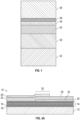
- FIG. 1 is a schematic cross-sectional view of an upper portion of a MEMS resonator device including a piezoelectric material 22 and a top side electrode 28, wherein at least the top side electrode 28 is overlaid with a hermeticity layer 32, an interface layer 34, a self-assembled monolayer 36, and a functionalization layer (e.g., specific binding material) 38.
- a hermeticity layer 32 e.g., an interface layer 34
- a self-assembled monolayer 36 e.g., specific binding material
- the MEMS resonator device includes a bulk acoustic wave resonator device
- the piezoelectric material 22 includes aluminum nitride or zinc oxide material that includes a c-axis having an orientation distribution that is predominantly non-parallel (and may also be non-perpendicular) to normal of a face of the substrate.
- Such an orientation distribution enables creation of shear displacements, which beneficially enable operation of the MEMS resonator device with liquids, such as in a sensor and/or microfluidic device.
- the piezoelectric material includes a c-axis with a longitudinal orientation.
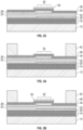
- FIG. 2A A representative bulk acoustic wave MEMS resonator device 10 suitable for receiving a passivation structure, a SAM, and at least one functionalization material (e.g., a specific binding material) is shown in FIG. 2A .
- the device 10 includes a substrate 12 (e.g., typically silicon or another semiconductor material), an acoustic reflector 14 arranged over the substrate 12, a layer of piezoelectric material 22, and bottom and top side electrodes 20, 28.
- the bottom side electrode 20 is arranged along a portion of a lower surface 24 of the piezoelectric material 22 (between the acoustic reflector 14 and the piezoelectric material 22), and the top side electrode 28 is arranged along a portion of an upper surface 26 of the piezoelectric material 22.
- An area in which the piezoelectric material 22 is arranged between overlapping portions of the top side electrode 28 and the bottom side electrode 20 is considered the active region 30 of the resonator device 10. At least a portion of each of the hermeticity layer, the interface layer, and the SAM is arranged over the at least one active region.
- the acoustic reflector 14 serves to reflect acoustic waves and therefore reduce or avoid their dissipation in the substrate 12.
- an acoustic reflector 14 includes alternating thin layers 16, 18 of different materials (e.g., silicon oxicarbide [SiOC], silicon nitride [Si 3 N 4 ], silicon dioxide [SiO 2 ], aluminum nitride [AIN], tungsten [W], and molybdenum [Mo]), optionally embodied in a quarter-wave Bragg mirror, deposited over the substrate 12.
- silicon oxicarbide [SiOC] silicon oxicarbide
- Si 3 N 4 silicon dioxide
- SiO 2 silicon dioxide
- AIN aluminum nitride
- tungsten [W] tungsten
- Mo molybdenum
- Steps for forming the resonator device 10 may include depositing the acoustic reflector 14 over the substrate 12, followed by deposition of the bottom side electrode 20, followed by growth (e.g., via sputtering or other appropriate methods) of the piezoelectric material 22, followed by deposition of the top side electrode 28.
- FIG. 2B is a schematic cross-sectional view of the MEMS resonator device 10 of FIG. 2A following deposition of a hermeticity layer 32 over the top side electrode 28 and portions of the piezoelectric material 22.
- the hermeticity layer 32 preferably includes a dielectric material with a low water vapor transmission rate (e.g., no greater than 0.1 (g/m 2 /day).
- the hermeticity layer 32 includes an oxide, a nitride, or an oxynitride material, such as (but not limited to) one or more of Al 2 O 3 , or SiO 2 .
- FIG. 2C is a schematic cross-sectional view of the coated MEMS resonator device of FIG. 2B following deposition of an interface layer 34 over the hermeticity layer 32.
- the interface layer 34 includes a hydroxylated oxide surface, and in certain embodiments may comprise one or more of silicon dioxide [SiO 2 ], titanium dioxide [TiO 2 ], tantalum pentoxide [Ta 2 O 5 ], hafnium oxide [HfO 2 ], or aluminum oxide [Al 2 O 3 ].
- FIG. 2D is a schematic cross-sectional view of the coated MEMS resonator device of FIG. 2C following formation of a self-assembled monolayer (SAM) 36 over the interface layer 34.
- the SAM includes an organosilane material. Examples of suitable SAM materials include GPTMS, MPTMS, APTMS, OTMS, and PEG organosilanes. Other examples of organosilane SAM materials and methods for their formation are well known to those skilled in the art.
- the SAM includes a thiol material.
- FIG. 2E is a schematic cross-sectional view of the MEMS resonator device of FIG. 2D following application of functionalization material 38 to a portion of the self-assembled monolayer 36 to overlap an active region 30 of the resonator device. As shown, the functionalization material 38 overlaps the active region 30 of the device.
- the device of FIG. 2E may be used as a sensor to detect presence of a target species in an environment. When an acoustic wave is induced in the active region 30, and functionalization material 38 is exposed to a target species that binds to the functionalization material 38, a change in one or more wave propagation properties (e.g., frequency, magnitude, and/or phase characteristics) of the device may be detected to indicate presence and/or quantity of target species in the environment.
- wave propagation properties e.g., frequency, magnitude, and/or phase characteristics
- a blocking layer may be arranged (e.g., patterned) over regions of a SAM in which a functionalization (e.g., specific binding) material is not present or not desired, with a blocking layer being useful to prevent non-specific binding of non-target species to a SAM.
- blocking materials include non-oxide thin films such as silicon nitride [SiN] or silicon carbide [SiC]; organic materials such as SU8, photoresist, polyimide, parylene, or polyethylene glycol) [PEG]; or chemical or biological buffers or proteins (such as bovine serum albumin (BSA)).
- a microfluidic device including a MEMS resonator device disclosed herein and including a fluidic passage arranged to conduct a liquid to contact at least one functionalization material.
- a fluidic device may be fabricated by forming one or more walls defining lateral boundaries of a microfluidic channel preferably containing the active region of at least one acoustic resonator, followed by application of a cover or cap layer to enclose the microfluidic channel.
- functionalization e.g., specific binding
- material may be applied following formation of walls of a microfluidic channel, but prior to application of the cover or cap layer.
- FIGS. 3A-3D illustrate formation of a fluidic device including a bulk acoustic wave MEMS resonator device.
- FIG. 3A is a schematic cross-sectional view of the MEMS resonator device of FIG. 2D following formation of walls 42 to define lateral boundaries of a microfluidic channel containing the active region of the MEMS resonator device.
- the MEMS resonator device includes a substrate 12, an acoustic reflector 14 arranged over the substrate 12, a layer of piezoelectric material 22, and bottom and top side electrodes 20, 28 arranged under and over regions of the piezoelectric material 22, respectively.
- An area in which the piezoelectric material 22 is arranged between overlapping portions of the top side electrode 28 and the bottom side electrode 20 defines an active region 30.
- a hermeticity layer 32 is provided over the top side electrode 28 and the piezoelectric material 22, an interface layer 34 is arranged over the hermeticity layer 32, and a SAM 36 is provided over the interface layer 34.
- Walls 42 that are laterally displaced from the active region 30 extend upward from the SAM 36 to define lateral boundaries of a microfluidic channel containing the active region 30.
- Such walls may be formed of any suitable material, such as SU-8 negative epoxy resist, other photoresist material, or laser-cut "stencil" layers of thin polymeric materials optionally including one or more self-adhesive surfaces (e.g., adhesive tape).
- such walls 42 may be formed prior to deposition of a SAM and functionalization and blocking layers with an SU-8 negative epoxy resist or other photoresist material.
- FIG. 3B is a schematic cross-sectional view of the device of FIG. 3A following application of functionalization (e.g., specific binding) material 38 to a portion of the SAM 36 to overlap the active region 30 of the resonator device.
- the functionalization material 38 may be applied on or over the SAM 36 using a microarray spotting needle or other suitable methods, with the functionalization material 38 preferably overlapping the active region 30.
- FIG. 3C is a schematic cross-sectional view of the device of FIG. 3B following application of a blocking material 40 over portions of the SAM 36 non-coincident with the active region 30.
- a blocking material may include bovine serum albumin (BSA).
- FIG. 3D is a schematic cross-sectional view of the device of FIG. 3C following application of a cover or cap layer 44 over the walls 42 to yield a microfluidic device 50 including an enclosed microfluidic channel 52 containing the active region 30 overlaid with functionalization material 38.
- the cover or cap layer 44 includes ports 46, 48 that may be used to supply fluid (e.g., liquid) into the microfluidic channel 52.
- the cover or cap layer 44 may embody any suitable material compatible with the fluid, and the cover or cap layer 44 may be optically transmissive in certain embodiments.
- cover or cap layer 44 examples include, but are not limited to, polymeric materials such as polypropylene, polyethylene, polycarbonate, and the like, or inorganic, nonmetallic materials such as ceramics or glasses.
- liquid may be supplied through one of the ports 46, 48 into the microfluidic channel 52 to contact the functionalization material 38.
- a change in one or more wave propagation properties e.g., frequency, magnitude, and/or phase characteristics
- the hermeticity layer 32 prevents the liquid from corroding the top side electrode 28, while the interface layer 34 facilitates attachment of the SAM 36 that enables application of the functionalization material 38.
- FIG. 4 is a top plan view photograph of a bulk acoustic wave MEMS resonator device 10 (consistent with the device 10 illustrated in FIG. 2A ) suitable for receiving a hermeticity layer, an interface layer, a self-assembled monolayer, and functionalization (e.g., specific binding) material as disclosed herein.
- the MEMS resonator device 10 includes a piezoelectric material (not shown) arranged over a substrate 12, a bottom side electrode 20 arranged under a portion of the piezoelectric material, and a top side electrode 28 arranged over a portion of the piezoelectric material, including an active region 30 in which the piezoelectric material is arranged between overlapping portions of the top side electrode 28 and the bottom side electrode 20.
- Externally accessible contacts 20A, 28A are in electrical communication with the bottom side electrode 20 and the top side electrode 28, respectively.
- the MEMS resonator device 10 is overlaid with an interface layer, a self-assembled monolayer, and functionalization (e.g., specific binding) material as disclosed herein, the device 10 may be used as a sensor and/or incorporated into a microfluidic device. If desired, multiple MEMS resonator devices 10 may be provided in an array on a single substrate 12.
- FIG. 5 is a perspective assembly view of a microfluidic device 60 incorporating a substrate 62 with multiple bulk acoustic wave MEMS resonator devices, an intermediate layer 80 defining a central microfluidic channel 82 registered with active regions 68A-68N of the MEMS resonator devices, and a cover or cap layer 90 arranged to cover the intermediate layer 80.
- Top central portions of the substrate 62 which includes an acoustic reflector (not shown) and a piezoelectric material (not shown), include a top side electrode 66 and bottom side electrodes 64A-64N. Regions in which the foregoing electrodes overlap one another and encompass the piezoelectric material embody active regions 68A-68N.
- Top peripheral (or top end) portions of the substrate 62 further include reference top side electrodes 76 and reference bottom side electrodes 74 in communication with reference overlap regions 70.
- Such reference overlap regions 70 are not exposed to fluid, and are present to provide a basis for comparing signals obtained from the active regions 68A-68N exposed to fluid within the central microfluidic channel 82.
- the substrate 62 is overlaid with the intermediate layer 80, wherein the central microfluidic channel 82 is intended to receive fluid, and defines peripheral chambers 84 arranged to overlie the reference overlap regions 70 in a sealed fashion.
- the intermediate layer 80 may be formed of any suitable material such as SU-8 negative epoxy resist, other photoresist material, or laser-cut "stencil" layers of thin polymeric materials optionally including one or more self-adhesive surfaces (e.g., adhesive tape), etc.
- the intermediate layer 80 further includes a lateral inset region 86 that enables lateral portions of the top side electrode 66 and bottom side electrodes 64A-64N to be accessed upon assembly of the microfluidic device 60.
- the cover or cap layer 90 includes a lateral inset region 96 registered with the lateral inset region 86 of the intermediate layer 80, and includes microfluidic ports 92, 94 accessible along a top surface 98 and registered with end portions of the central microfluidic channel 82 defined in the intermediate layer 80 to permit fluid (e.g., liquid) to be supplied to the central microfluidic channel 82 over the active regions 68A-68N.
- fluid e.g., liquid
- at least the electrodes 64A-64N, 66 are overlaid with a hermeticity layer, an interface layer, a self-assembled monolayer, and functionalization (e.g., specific binding) material as disclosed herein.
- Microfluidic devices according to other configurations may be provided, as will be recognized by those skilled in the art upon review of the present disclosure.
- FIG. 6 is a schematic cross-sectional view of a film bulk acoustic wave resonator (FBAR) structure 100 including an active region, with at least portions of the FBAR structure 100 subject to being overlaid with an interface layer and a self-assembled monolayer (SAM) suitable for receiving a functionalization material (e.g., specific binding or non-specific binding material), according to one embodiment.
- the FBAR structure 100 includes a substrate 102 (e.g., silicon or another semiconductor material) defining a cavity 106 that is covered by a support layer 108 (e.g., silicon dioxide).
- a bottom side electrode 110 is arranged over a portion of the support layer 108, a piezoelectric material layer 112, preferably embodying inclined c-axis hexagonal crystal structure piezoelectric material (e.g., AIN or ZnO), is arranged over the bottom side electrode 110 and the support layer 108, and a top side electrode 116 is arranged over at least a portion of a top surface 114 of the piezoelectric material layer 112.
- a portion of the piezoelectric material layer 112 arranged between the top side electrode 116 and the bottom side electrode 110 embodies an active region 120 of the FBAR structure 100.
- the active region 120 is arranged over and registered with the cavity 106 disposed below the support layer 108.
- the cavity 106 serves to confine acoustic waves induced in the active region 120 by preventing dissipation of acoustic energy into the substrate 102, since acoustic waves do not efficiently propagate across the cavity 106.
- the cavity 106 provides an alternative to the acoustic reflector 14 illustrated in FIGS. 2A-3D .
- the cavity 106 shown in FIG. 6 is bounded from below by a thinned portion of the substrate 102, in alternative embodiments at least a portion of the cavity 106 may extend through an entire thickness of the substrate 102.
- Steps for forming the FBAR structure 100 may include defining the cavity 106 in the substrate 102, filling the cavity 106 with a sacrificial material (not shown) optionally followed by planarization of the sacrificial material, depositing the support layer 108 over the substrate 102 and the sacrificial material, removing the sacrificial material (e.g., by flowing an etchant through vertical openings defined in the substrate 102 or the support layer 108, or lateral edges of the substrate 102), depositing the bottom side electrode 110 over the support layer 108, growing (e.g., via sputtering or other appropriate methods) the piezoelectric material layer 112, and depositing the top side electrode 116.
- the FBAR structure 100 of FIG. 6 may be substituted for solidly mounted BAW structures as disclosed in FIGS. 2A-3D , with at least portions of the bulk acoustic wave structures being overlaid with an interface layer and a self-assembled monolayer suitable for receiving a functionalization material (e.g., specific binding or non-specific binding material),
- a functionalization material e.g., specific binding or non-specific binding material
Landscapes
- Physics & Mathematics (AREA)
- Health & Medical Sciences (AREA)
- Life Sciences & Earth Sciences (AREA)
- Chemical & Material Sciences (AREA)
- Analytical Chemistry (AREA)
- Biochemistry (AREA)
- General Health & Medical Sciences (AREA)
- General Physics & Mathematics (AREA)
- Immunology (AREA)
- Pathology (AREA)
- Acoustics & Sound (AREA)
- Piezo-Electric Or Mechanical Vibrators, Or Delay Or Filter Circuits (AREA)
- Engineering & Computer Science (AREA)
- Manufacturing & Machinery (AREA)
Claims (15)
- Mikroelektromechanische Systemresonatorvorrichtung, MEMS-Resonatorvorrichtung, (10) für Bioerfassung oder biochemische Erfassungsanwendungen, wobei die Vorrichtung umfasst:ein Substrat (12);eine akustische Volumenwellenresonatorstruktur, die über wenigstens einem Abschnitt des Substrats angeordnet ist, wobei die akustische Volumenwellenresonatorstruktur wenigstens eine oberseitige Elektrode (28) beinhaltet;eine Hermitezitätsschicht (32), die über wenigstens einem Abschnitt der wenigstens einen oberseitigen Elektrode angeordnet ist, wobei die Hermitezitätsschicht ein dielektrisches Material umfasst, das eine Wasserdampfdurchlässigkeitsrate von nicht mehr als 0,1 g/m2/Tag beinhaltet;eine Grenzflächenschicht (34), die über wenigstens einem Abschnitt der Hermitezitätsschicht angeordnet ist;eine selbst zusammengebaute Monoschicht, die über wenigstens einem Abschnitt der Grenzflächenschicht angeordnet ist;wenigstens ein spezifisches Bindematerial (38), das über wenigstens einem Abschnitt der selbst zusammengebauten Monoschicht angeordnet ist; undein Blockiermaterial (40), das über einem Abschnitt der selbst zusammengebauten Monoschicht angeordnet ist, das nicht mit dem wenigstens einen spezifischen Bindungsmaterial zusammenfällt;wobei die akustische Volumenwellenresonatorstruktur wenigstens einen aktiven Bereich (30) unterhalb der wenigstens einen oberseitigen Elektrode umfasst und wenigstens ein Abschnitt von jeder der Hermitezitätsschicht, der Grenzflächenschicht, der selbst zusammengebauten Monoschicht und des wenigstens einen spezifischen Bindematerials oberhalb des wenigstens einen aktiven Bereichs angeordnet ist.
- MEMS-Resonatorvorrichtung nach Anspruch 1, wobei die Grenzflächenschicht eine hydroxylierte Oxidoberfläche umfasst, und die selbst zusammengebaute Monoschicht ein Organosilanmaterial umfasst.
- MEMS-Resonatorvorrichtung nach Anspruch 1, wobei die Grenzflächenschicht Gold oder ein anderes Edelmetall umfasst und die selbst zusammengebaute Monoschicht ein Thiolmaterial umfasst.
- MEMS-Resonatorvorrichtung nach Anspruch 1,wobei die Hermitezitätsschicht ein Oxid, ein Nitrid oder ein Oxynitridmaterial umfasst, oderwobei die Grenzflächenschicht wenigstens eines von SiO2, TiO2, Ta2O5, HfO2 oder Al2O3 umfasst, oderwobei die wenigstens eine oberseitige Elektrode ein Nichtedelmetall umfasst.
- MEMS-Resonatorvorrichtung nach Anspruch 1, wobei die Hermitezitätsschicht eine Dicke in einem Bereich von etwa 5 nm bis etwa 150 nm umfasst, und die Grenzflächenschicht eine Dicke in einem Bereich von etwa 5 nm bis etwa 15 nm umfasst.
- MEMS-Resonatorvorrichtung nach Anspruch 1, wobei die akustische Volumenwellenresonatorstruktur ein piezoelektrisches Material (22) mit hexagonaler Kristallstruktur umfasst, das eine c-Achse mit einer Orientierungsverteilung umfasst, die überwiegend nicht parallel bis senkrecht zu einer Fläche des Substrats ist.
- MEMS-Resonatorvorrichtung nach Anspruch 1, ferner umfassend eine akustische Reflektorstruktur (14), die zwischen dem Substrat und der akustischen Volumenwellenresonatorstruktur angeordnet ist, wobei die akustische Volumenwellenresonatorstruktur eine fest montierte akustische Volumenwellenresonatorstruktur umfasst.
- MEMS-Resonatorvorrichtung nach Anspruch 1, wobei das Substrat eine Vertiefung (106) definiert, eine Trägerschicht (108) zwischen der akustischen Volumenwellenresonatorstruktur und der Vertiefung bereitgestellt wird, und der wenigstens eine aktive Bereich über wenigstens einem Abschnitt der Trägerschicht und wenigstens einem Abschnitt der Vertiefung angeordnet ist.
- Sensor, der die MEMS-Resonatorvorrichtung nach Anspruch 1 umfasst.
- Fluidische Vorrichtung, umfassend die MEMS-Resonatorvorrichtung nach Anspruch 1 und einen fluidischen Kanal, der angeordnet ist, um eine Flüssigkeit zu leiten, um das wenigstens eine spezifische Bindungsmaterial zu berühren.
- Verfahren zum biologischen oder chemischen Erfassen, wobei das Verfahren umfasst:Zuführen eines Fluid, das eine Zielspezies enthält, in den fluidischen Kanal der fluidischen Vorrichtung nach Anspruch 10, wobei das Zuführen dazu konfiguriert ist, zu bewirken, dass wenigstens ein Teil der Zielspezies an das wenigstens eine spezifische Bindematerial bindet;Induzieren einer akustischen Volumenwelle in dem wenigstens einen aktiven Bereich; undErfassen einer Änderung von wenigstens einer einer Frequenzeigenschaft, einer Größeneigenschaft oder einer Phaseneigenschaft der akustischen Volumenwellenresonatorstruktur, um wenigstens eines des Vorhandenseins oder der Menge einer Zielspezies anzuzeigen, die an das wenigstens eine spezifische Bindematerial gebunden ist.
- Verfahren zum Herstellen einer mikroelektromechanischen Systemresonatorvorrichtung, MEMS-Resonatorvorrichtung, (10) für Bioerfassung oder biochemische Erfassungsanwendungen, wobei das Verfahren umfasst:Ausbilden wenigstens einer oberseitigen Elektrode (28) über wenigstens einem Abschnitt eines piezoelektrischen Materials (22), das über wenigstens einem Abschnitt eines Substrats (12) angeordnet ist;Abscheiden einer Hermitezitätsschicht (32) über wenigstens einem Abschnitt der wenigstens einen oberseitigen Elektrode, wobei die Hermitezitätsschicht ein dielektrisches Material umfasst, das eine Wasserdampfdurchlässigkeitsrate von nicht mehr als 0,1 g/m2/Tag umfasst,Abscheiden einer Grenzflächenschicht (34) über wenigstens einem Abschnitt der Hermitezitätsschicht;Ausbilden einer selbst zusammengebauten Monoschicht über wenigstens einem Abschnitt der Grenzfläche;Abscheiden wenigstens eines spezifischen Bindematerials (38) über wenigstens einem Abschnitt der selbst zusammengebauten Monoschicht; undAbscheiden eines Blockiermaterials (40) über einem Abschnitt der selbst zusammengebauten Monoschicht, das nicht mit dem wenigstens einen spezifischen Bindungsmaterial zusammenfällt;wobei die akustische Volumenwellenresonatorstruktur wenigstens einen aktiven Bereich (30) unterhalb der wenigstens einen oberseitigen Elektrode umfasst und wenigstens ein Abschnitt von jeder der Hermitezitätsschicht, der Grenzflächenschicht, der selbst zusammengebauten Monoschicht und des wenigstens einen spezifischen Bindematerials oberhalb des wenigstens einen aktiven Bereichs angeordnet ist.
- Verfahren nach Anspruch 12, wobei das Abscheiden der Hermitezitätsschicht die Atomschichtabscheidung umfasst, und das Abscheiden der Grenzflächenschicht wenigstens eine der chemischen Gasphasenabscheidung, der Atomschichtabscheidung oder des physikalischen Aufdampfens umfasst.
- Verfahren nach Anspruch 12, wobei das Abscheiden der Grenzflächenschicht nach der Abscheidung der Hermitezitätsschicht in einer Vakuumumgebung nacheinander durchgeführt wird.
- Verfahren nach Anspruch 12, das ferner das Ausbilden wenigstens einer Wand (42) über einem Abschnitt der Grenzflächenschicht umfasst und einen fluidischen Kanal definiert.
Applications Claiming Priority (2)
| Application Number | Priority Date | Filing Date | Title |
|---|---|---|---|
| US201562252402P | 2015-11-06 | 2015-11-06 | |
| PCT/US2016/058745 WO2017078992A1 (en) | 2015-11-06 | 2016-10-26 | Acoustic resonator devices and fabrication methods providing hermeticity and surface functionalization |
Publications (2)
| Publication Number | Publication Date |
|---|---|
| EP3371583A1 EP3371583A1 (de) | 2018-09-12 |
| EP3371583B1 true EP3371583B1 (de) | 2024-08-14 |
Family
ID=57256432
Family Applications (1)
| Application Number | Title | Priority Date | Filing Date |
|---|---|---|---|
| EP16794124.4A Active EP3371583B1 (de) | 2015-11-06 | 2016-10-26 | Akustische resonatorvorrichtungen und herstellungsverfahren mit bereitstellung von dichtigkeit und oberflächenfunktionalisierung |
Country Status (5)
| Country | Link |
|---|---|
| US (1) | US10302595B2 (de) |
| EP (1) | EP3371583B1 (de) |
| JP (1) | JP6882280B2 (de) |
| CN (1) | CN108474764B (de) |
| WO (1) | WO2017078992A1 (de) |
Families Citing this family (15)
| Publication number | Priority date | Publication date | Assignee | Title |
|---|---|---|---|---|
| US10352904B2 (en) | 2015-10-26 | 2019-07-16 | Qorvo Us, Inc. | Acoustic resonator devices and methods providing patterned functionalization areas |
| US10371667B2 (en) * | 2015-11-16 | 2019-08-06 | Qorvo Us, Inc. | BAW sensor with passive mixing structures |
| US10267770B2 (en) | 2016-07-27 | 2019-04-23 | Qorvo Us, Inc. | Acoustic resonator devices and methods with noble metal layer for functionalization |
| WO2018031055A1 (en) | 2016-08-11 | 2018-02-15 | Qorvo Us, Inc. | Acoustic resonator device with controlled placement of functionalization material |
| WO2020227396A1 (en) | 2019-05-06 | 2020-11-12 | Qorvo Biotechnologies, Llc | Acoustic resonator device |
| US12445109B2 (en) | 2019-07-31 | 2025-10-14 | QXONIX Inc. | Structures, acoustic wave resonators, layers, devices and systems |
| US12431861B2 (en) | 2019-07-31 | 2025-09-30 | Qxoniix Inc. | Layers, structures, acoustic wave resonators, devices and systems |
| US12451860B2 (en) | 2019-07-31 | 2025-10-21 | QXONIX Inc. | Structures, acoustic wave resonators, devices and systems |
| WO2021021723A1 (en) | 2019-07-31 | 2021-02-04 | QXONIX Inc. | Acoustic device structures, devices and systems |
| US11401601B2 (en) * | 2019-09-13 | 2022-08-02 | Qorvo Us, Inc. | Piezoelectric bulk layers with tilted c-axis orientation and methods for making the same |
| JP7378723B2 (ja) * | 2019-09-30 | 2023-11-14 | 国立大学法人東北大学 | 弾性波デバイス |
| US12031949B2 (en) * | 2019-11-15 | 2024-07-09 | Qorvo Us, Inc. | Preventing epoxy bleed-out for biosensor devices |
| DE112020006201T5 (de) * | 2019-12-19 | 2022-11-17 | Qorvo Us, Inc. | Resonatorstruktur zur Massenerfassung |
| CN111351848B (zh) * | 2020-03-19 | 2020-10-16 | 山东科技大学 | 一种传感器的制备方法、传感器以及传感器的检测方法 |
| CN114900147B (zh) * | 2022-07-08 | 2022-11-01 | 深圳新声半导体有限公司 | 体声波谐振器及其制造方法 |
Family Cites Families (39)
| Publication number | Priority date | Publication date | Assignee | Title |
|---|---|---|---|---|
| SU490006A1 (ru) * | 1974-05-15 | 1975-10-30 | Ленинградский электротехнический институт | Ультразвуковой преобразователь |
| US4640756A (en) | 1983-10-25 | 1987-02-03 | The United States Of America As Represented By The United States Department Of Energy | Method of making a piezoelectric shear wave resonator |
| JPH0617897B2 (ja) * | 1985-05-23 | 1994-03-09 | 住友ベ−クライト株式会社 | ガス濃度測定装置 |
| JPH0946793A (ja) * | 1995-07-31 | 1997-02-14 | Taiyo Yuden Co Ltd | 圧電要素及び圧電音響装置 |
| US6320295B1 (en) * | 1998-11-18 | 2001-11-20 | Mcgill Robert Andrew | Diamond or diamond like carbon coated chemical sensors and a method of making same |
| JP2001251159A (ja) * | 2000-03-08 | 2001-09-14 | Mitsubishi Electric Corp | 薄膜圧電素子及びその製造方法 |
| JP3984441B2 (ja) * | 2001-07-26 | 2007-10-03 | 松下電器産業株式会社 | 圧電薄膜振動子及びフィルタ |
| JP3908512B2 (ja) * | 2001-11-16 | 2007-04-25 | セイコーインスツル株式会社 | 圧電トランスデューサ及び脈波検出装置 |
| US7989851B2 (en) * | 2002-06-06 | 2011-08-02 | Rutgers, The State University Of New Jersey | Multifunctional biosensor based on ZnO nanostructures |
| WO2004017063A2 (de) | 2002-07-19 | 2004-02-26 | Siemens Aktiengesellschaft | Vorrichtung und verfahren zur detektion einer substanz mithilfe eines hochfrequenten piezoakustischen dünnfilmresonators |
| DE10318956A1 (de) * | 2003-04-26 | 2004-11-11 | Kanesho Soil Treatment Bvba | Verfahren und Vorrichtung zum Nachweis von flüchtigen Analyten in Luftproben |
| CN100567972C (zh) * | 2003-10-08 | 2009-12-09 | 皇家飞利浦电子股份有限公司 | 体声波传感器 |
| US20050148065A1 (en) * | 2003-12-30 | 2005-07-07 | Intel Corporation | Biosensor utilizing a resonator having a functionalized surface |
| US7134319B2 (en) * | 2004-08-12 | 2006-11-14 | Honeywell International Inc. | Acoustic wave sensor with reduced condensation and recovery time |
| WO2006063437A1 (en) | 2004-12-15 | 2006-06-22 | University Of Guelph | Prion sensors for diagnosis of transmissible spongiform encephalopathy or for detection of prions, and use thereof |
| CN101133321B (zh) * | 2005-04-06 | 2011-04-13 | 株式会社村田制作所 | 表面波传感器器件 |
| FI118829B (fi) * | 2005-07-08 | 2008-03-31 | Valtion Teknillinen | Mikromekaaninen sensori, sensoriryhmä ja menetelmä sekä pitkittäisten akustisten aaltojen uusi käyttö |
| JP4913863B2 (ja) * | 2006-04-20 | 2012-04-11 | デラウェア キャピタル フォーメーション インク | 過酷な環境用の被膜およびそれを用いたセンサ |
| JP4432990B2 (ja) * | 2007-03-22 | 2010-03-17 | セイコーエプソン株式会社 | センサ及び電子機器 |
| JP2009207075A (ja) * | 2008-02-29 | 2009-09-10 | Tdk Corp | 共振子フィルタの製造方法 |
| CN101246162A (zh) * | 2008-03-12 | 2008-08-20 | 浙江大学 | 利用压电薄膜体声波器件的抗体检测生物芯片 |
| US8448494B2 (en) | 2008-12-30 | 2013-05-28 | Stmicroelectronics S.R.L. | Integrated electronic microbalance plus chemical sensor |
| FI20096201A0 (fi) * | 2009-11-19 | 2009-11-19 | Valtion Teknillinen | Massa-aaltoresonaattori ja menetelmä sen valmistamiseksi |
| US20110121916A1 (en) * | 2009-11-24 | 2011-05-26 | Avago Technologies Wireless Ip (Singapore) Pte. Ltd. | Hybrid bulk acoustic wave resonator |
| CN103403538B (zh) | 2010-10-20 | 2016-06-01 | 快速诊断技术公司 | 利用共振传感器测量结合动力的装置和方法 |
| US8698569B2 (en) * | 2011-02-21 | 2014-04-15 | Panasonic Corporation | MEMS resonator |
| US8896395B2 (en) * | 2011-09-14 | 2014-11-25 | Avago Technologies General Ip (Singapore) Pte. Ltd. | Accoustic resonator having multiple lateral features |
| CN102608172A (zh) * | 2012-03-12 | 2012-07-25 | 山东科技大学 | 具有直流电极的薄膜体声波谐振生化传感器 |
| CN102778509A (zh) * | 2012-08-17 | 2012-11-14 | 天津理工大学 | 一种声表面波气体传感器基片 |
| CN104034798A (zh) * | 2013-03-07 | 2014-09-10 | 浙江工商大学 | 细胞悬液浓度检测系统及其检测方法 |
| CN103454345B (zh) * | 2013-08-20 | 2016-01-13 | 西安交通大学 | 基于cmut的海洋生化物质监测传感器及其制备与测量方法 |
| JP6284076B2 (ja) * | 2013-11-22 | 2018-02-28 | 国立大学法人豊橋技術科学大学 | 物理・化学センサおよび特定物質の測定方法 |
| US9910015B2 (en) * | 2014-04-14 | 2018-03-06 | Texas Instruments Incorporated | Sensor array chip with piezoelectric transducer including inkjet forming method |
| CN104330470B (zh) * | 2014-09-30 | 2018-04-10 | 成都柏森松传感技术有限公司 | 基于saw传感器的检测装置 |
| CN105157935A (zh) * | 2015-08-09 | 2015-12-16 | 安徽普为智能科技有限责任公司 | 一种锂电池气密均匀性的检测方法 |
| US10541663B2 (en) | 2015-10-14 | 2020-01-21 | Qorvo Us, Inc. | Multi-stage deposition system for growth of inclined c-axis piezoelectric material structures |
| US10352904B2 (en) | 2015-10-26 | 2019-07-16 | Qorvo Us, Inc. | Acoustic resonator devices and methods providing patterned functionalization areas |
| US10267770B2 (en) | 2016-07-27 | 2019-04-23 | Qorvo Us, Inc. | Acoustic resonator devices and methods with noble metal layer for functionalization |
| WO2018031055A1 (en) | 2016-08-11 | 2018-02-15 | Qorvo Us, Inc. | Acoustic resonator device with controlled placement of functionalization material |
-
2016
- 2016-10-26 JP JP2018522723A patent/JP6882280B2/ja active Active
- 2016-10-26 WO PCT/US2016/058745 patent/WO2017078992A1/en not_active Ceased
- 2016-10-26 US US15/334,528 patent/US10302595B2/en active Active
- 2016-10-26 EP EP16794124.4A patent/EP3371583B1/de active Active
- 2016-10-26 CN CN201680078230.7A patent/CN108474764B/zh active Active
Non-Patent Citations (2)
| Title |
|---|
| LUNGENSCHMIED CRISTOPH ET AL: "Flexible Encapsulation For Organic Solar Cells", PROCEEDINGS OF SPIE, 1 May 2006 (2006-05-01), pages 619712 - 1, XP055853812, Retrieved from the Internet <URL:https://www.researchgate.net/publication/228548371_Flexible_encapsulation_for_organic_solar_cells> [retrieved on 20211021], DOI: 10.1117/12.662829 * |
| ULTRATECH CNT: "Encapsulation Barrier Layers", PUBLICATION REVIEW ON SAVANNAH & FIJI, 20 July 2015 (2015-07-20), pages 1 - 9, XP055853798, Retrieved from the Internet <URL:https://s3.amazonaws.com/veeco-media-file/wp-content/uploads/2020/04/07074628/cf648f046a9579736b324d1e6330b501.pdf> [retrieved on 20211021] * |
Also Published As
| Publication number | Publication date |
|---|---|
| CN108474764B (zh) | 2021-12-10 |
| JP6882280B2 (ja) | 2021-06-02 |
| CN108474764A (zh) | 2018-08-31 |
| US20170134001A1 (en) | 2017-05-11 |
| EP3371583A1 (de) | 2018-09-12 |
| JP2018533310A (ja) | 2018-11-08 |
| US10302595B2 (en) | 2019-05-28 |
| WO2017078992A1 (en) | 2017-05-11 |
Similar Documents
| Publication | Publication Date | Title |
|---|---|---|
| EP3371583B1 (de) | Akustische resonatorvorrichtungen und herstellungsverfahren mit bereitstellung von dichtigkeit und oberflächenfunktionalisierung | |
| US11695384B2 (en) | Acoustic resonator device with controlled placement of functionalization material | |
| US10618045B2 (en) | Sensor device with BAW resonator and through-substrate fluidic vias | |
| EP3427043B1 (de) | Fluidische vorrichtung eines baw-sensors mit erhöhtem dynamischem messbereich | |
| EP3365669B1 (de) | Resonatorstruktur mit erhöhter reflexion von scher- und longitudinalen moden akustischer schwingungen | |
| US10458982B2 (en) | Fluidic device including BAW resonators along opposing channel surfaces | |
| US10352904B2 (en) | Acoustic resonator devices and methods providing patterned functionalization areas | |
| US10371667B2 (en) | BAW sensor with passive mixing structures | |
| US12498352B2 (en) | Fluidic device with fluid port orthogonal to functionalized active region | |
| US11353428B2 (en) | BAW sensor device with peel-resistant wall structure | |
| US10659000B2 (en) | Fluidic sensor device having UV-blocking cover | |
| WO2017083131A1 (en) | Baw sensor with enhanced surface area active region | |
| HK1260247A1 (en) | Acoustic resonator devices and fabrication methods providing hermeticity and surface functionalization | |
| HK1260247B (zh) | 声学谐振器设备和提供气密性及表面功能化的制造方法 |
Legal Events
| Date | Code | Title | Description |
|---|---|---|---|
| STAA | Information on the status of an ep patent application or granted ep patent |
Free format text: STATUS: UNKNOWN |
|
| STAA | Information on the status of an ep patent application or granted ep patent |
Free format text: STATUS: THE INTERNATIONAL PUBLICATION HAS BEEN MADE |
|
| PUAI | Public reference made under article 153(3) epc to a published international application that has entered the european phase |
Free format text: ORIGINAL CODE: 0009012 |
|
| STAA | Information on the status of an ep patent application or granted ep patent |
Free format text: STATUS: REQUEST FOR EXAMINATION WAS MADE |
|
| 17P | Request for examination filed |
Effective date: 20180416 |
|
| AK | Designated contracting states |
Kind code of ref document: A1 Designated state(s): AL AT BE BG CH CY CZ DE DK EE ES FI FR GB GR HR HU IE IS IT LI LT LU LV MC MK MT NL NO PL PT RO RS SE SI SK SM TR |
|
| AX | Request for extension of the european patent |
Extension state: BA ME |
|
| DAV | Request for validation of the european patent (deleted) | ||
| DAX | Request for extension of the european patent (deleted) | ||
| RIN1 | Information on inventor provided before grant (corrected) |
Inventor name: BELSICK, JOHN Inventor name: MORTON, RICK Inventor name: RYDER, MATTHEW |
|
| STAA | Information on the status of an ep patent application or granted ep patent |
Free format text: STATUS: EXAMINATION IS IN PROGRESS |
|
| 17Q | First examination report despatched |
Effective date: 20211028 |
|
| P01 | Opt-out of the competence of the unified patent court (upc) registered |
Effective date: 20230505 |
|
| RAP1 | Party data changed (applicant data changed or rights of an application transferred) |
Owner name: QORVO BIOTECHNOLOGIES, LLC |
|
| GRAP | Despatch of communication of intention to grant a patent |
Free format text: ORIGINAL CODE: EPIDOSNIGR1 |
|
| STAA | Information on the status of an ep patent application or granted ep patent |
Free format text: STATUS: GRANT OF PATENT IS INTENDED |
|
| RIC1 | Information provided on ipc code assigned before grant |
Ipc: H03H 9/17 20060101ALI20231123BHEP Ipc: G01N 29/22 20060101ALI20231123BHEP Ipc: G01N 29/24 20060101ALI20231123BHEP Ipc: G01N 29/02 20060101AFI20231123BHEP |
|
| INTG | Intention to grant announced |
Effective date: 20231208 |
|
| RAP1 | Party data changed (applicant data changed or rights of an application transferred) |
Owner name: QORVO US, INC. |
|
| GRAJ | Information related to disapproval of communication of intention to grant by the applicant or resumption of examination proceedings by the epo deleted |
Free format text: ORIGINAL CODE: EPIDOSDIGR1 |
|
| STAA | Information on the status of an ep patent application or granted ep patent |
Free format text: STATUS: EXAMINATION IS IN PROGRESS |
|
| GRAP | Despatch of communication of intention to grant a patent |
Free format text: ORIGINAL CODE: EPIDOSNIGR1 |
|
| STAA | Information on the status of an ep patent application or granted ep patent |
Free format text: STATUS: GRANT OF PATENT IS INTENDED |
|
| INTC | Intention to grant announced (deleted) | ||
| INTG | Intention to grant announced |
Effective date: 20240422 |
|
| GRAS | Grant fee paid |
Free format text: ORIGINAL CODE: EPIDOSNIGR3 |
|
| GRAA | (expected) grant |
Free format text: ORIGINAL CODE: 0009210 |
|
| STAA | Information on the status of an ep patent application or granted ep patent |
Free format text: STATUS: THE PATENT HAS BEEN GRANTED |
|
| AK | Designated contracting states |
Kind code of ref document: B1 Designated state(s): AL AT BE BG CH CY CZ DE DK EE ES FI FR GB GR HR HU IE IS IT LI LT LU LV MC MK MT NL NO PL PT RO RS SE SI SK SM TR |
|
| REG | Reference to a national code |
Ref country code: GB Ref legal event code: FG4D |
|
| REG | Reference to a national code |
Ref country code: CH Ref legal event code: EP |
|
| REG | Reference to a national code |
Ref country code: DE Ref legal event code: R096 Ref document number: 602016088902 Country of ref document: DE |
|
| REG | Reference to a national code |
Ref country code: IE Ref legal event code: FG4D |
|
| REG | Reference to a national code |
Ref country code: LT Ref legal event code: MG9D |
|
| REG | Reference to a national code |
Ref country code: NL Ref legal event code: MP Effective date: 20240814 |
|
| PGFP | Annual fee paid to national office [announced via postgrant information from national office to epo] |
Ref country code: DE Payment date: 20240919 Year of fee payment: 9 |
|
| PG25 | Lapsed in a contracting state [announced via postgrant information from national office to epo] |
Ref country code: NO Free format text: LAPSE BECAUSE OF FAILURE TO SUBMIT A TRANSLATION OF THE DESCRIPTION OR TO PAY THE FEE WITHIN THE PRESCRIBED TIME-LIMIT Effective date: 20241114 |
|
| REG | Reference to a national code |
Ref country code: AT Ref legal event code: MK05 Ref document number: 1713724 Country of ref document: AT Kind code of ref document: T Effective date: 20240814 |
|
| PG25 | Lapsed in a contracting state [announced via postgrant information from national office to epo] |
Ref country code: GR Free format text: LAPSE BECAUSE OF FAILURE TO SUBMIT A TRANSLATION OF THE DESCRIPTION OR TO PAY THE FEE WITHIN THE PRESCRIBED TIME-LIMIT Effective date: 20241115 Ref country code: FI Free format text: LAPSE BECAUSE OF FAILURE TO SUBMIT A TRANSLATION OF THE DESCRIPTION OR TO PAY THE FEE WITHIN THE PRESCRIBED TIME-LIMIT Effective date: 20240814 Ref country code: NL Free format text: LAPSE BECAUSE OF FAILURE TO SUBMIT A TRANSLATION OF THE DESCRIPTION OR TO PAY THE FEE WITHIN THE PRESCRIBED TIME-LIMIT Effective date: 20240814 Ref country code: PL Free format text: LAPSE BECAUSE OF FAILURE TO SUBMIT A TRANSLATION OF THE DESCRIPTION OR TO PAY THE FEE WITHIN THE PRESCRIBED TIME-LIMIT Effective date: 20240814 Ref country code: PT Free format text: LAPSE BECAUSE OF FAILURE TO SUBMIT A TRANSLATION OF THE DESCRIPTION OR TO PAY THE FEE WITHIN THE PRESCRIBED TIME-LIMIT Effective date: 20241216 |
|
| PG25 | Lapsed in a contracting state [announced via postgrant information from national office to epo] |
Ref country code: BG Free format text: LAPSE BECAUSE OF FAILURE TO SUBMIT A TRANSLATION OF THE DESCRIPTION OR TO PAY THE FEE WITHIN THE PRESCRIBED TIME-LIMIT Effective date: 20240814 |
|
| PG25 | Lapsed in a contracting state [announced via postgrant information from national office to epo] |
Ref country code: LV Free format text: LAPSE BECAUSE OF FAILURE TO SUBMIT A TRANSLATION OF THE DESCRIPTION OR TO PAY THE FEE WITHIN THE PRESCRIBED TIME-LIMIT Effective date: 20240814 |
|
| PG25 | Lapsed in a contracting state [announced via postgrant information from national office to epo] |
Ref country code: AT Free format text: LAPSE BECAUSE OF FAILURE TO SUBMIT A TRANSLATION OF THE DESCRIPTION OR TO PAY THE FEE WITHIN THE PRESCRIBED TIME-LIMIT Effective date: 20240814 Ref country code: IS Free format text: LAPSE BECAUSE OF FAILURE TO SUBMIT A TRANSLATION OF THE DESCRIPTION OR TO PAY THE FEE WITHIN THE PRESCRIBED TIME-LIMIT Effective date: 20241214 |
|
| PG25 | Lapsed in a contracting state [announced via postgrant information from national office to epo] |
Ref country code: HR Free format text: LAPSE BECAUSE OF FAILURE TO SUBMIT A TRANSLATION OF THE DESCRIPTION OR TO PAY THE FEE WITHIN THE PRESCRIBED TIME-LIMIT Effective date: 20240814 |
|
| PG25 | Lapsed in a contracting state [announced via postgrant information from national office to epo] |
Ref country code: RS Free format text: LAPSE BECAUSE OF FAILURE TO SUBMIT A TRANSLATION OF THE DESCRIPTION OR TO PAY THE FEE WITHIN THE PRESCRIBED TIME-LIMIT Effective date: 20241114 Ref country code: ES Free format text: LAPSE BECAUSE OF FAILURE TO SUBMIT A TRANSLATION OF THE DESCRIPTION OR TO PAY THE FEE WITHIN THE PRESCRIBED TIME-LIMIT Effective date: 20240814 |
|
| PG25 | Lapsed in a contracting state [announced via postgrant information from national office to epo] |
Ref country code: BG Free format text: LAPSE BECAUSE OF FAILURE TO SUBMIT A TRANSLATION OF THE DESCRIPTION OR TO PAY THE FEE WITHIN THE PRESCRIBED TIME-LIMIT Effective date: 20240814 Ref country code: AT Free format text: LAPSE BECAUSE OF FAILURE TO SUBMIT A TRANSLATION OF THE DESCRIPTION OR TO PAY THE FEE WITHIN THE PRESCRIBED TIME-LIMIT Effective date: 20240814 Ref country code: RS Free format text: LAPSE BECAUSE OF FAILURE TO SUBMIT A TRANSLATION OF THE DESCRIPTION OR TO PAY THE FEE WITHIN THE PRESCRIBED TIME-LIMIT Effective date: 20241114 Ref country code: PT Free format text: LAPSE BECAUSE OF FAILURE TO SUBMIT A TRANSLATION OF THE DESCRIPTION OR TO PAY THE FEE WITHIN THE PRESCRIBED TIME-LIMIT Effective date: 20241216 Ref country code: PL Free format text: LAPSE BECAUSE OF FAILURE TO SUBMIT A TRANSLATION OF THE DESCRIPTION OR TO PAY THE FEE WITHIN THE PRESCRIBED TIME-LIMIT Effective date: 20240814 Ref country code: NO Free format text: LAPSE BECAUSE OF FAILURE TO SUBMIT A TRANSLATION OF THE DESCRIPTION OR TO PAY THE FEE WITHIN THE PRESCRIBED TIME-LIMIT Effective date: 20241114 Ref country code: NL Free format text: LAPSE BECAUSE OF FAILURE TO SUBMIT A TRANSLATION OF THE DESCRIPTION OR TO PAY THE FEE WITHIN THE PRESCRIBED TIME-LIMIT Effective date: 20240814 Ref country code: LV Free format text: LAPSE BECAUSE OF FAILURE TO SUBMIT A TRANSLATION OF THE DESCRIPTION OR TO PAY THE FEE WITHIN THE PRESCRIBED TIME-LIMIT Effective date: 20240814 Ref country code: IS Free format text: LAPSE BECAUSE OF FAILURE TO SUBMIT A TRANSLATION OF THE DESCRIPTION OR TO PAY THE FEE WITHIN THE PRESCRIBED TIME-LIMIT Effective date: 20241214 Ref country code: HR Free format text: LAPSE BECAUSE OF FAILURE TO SUBMIT A TRANSLATION OF THE DESCRIPTION OR TO PAY THE FEE WITHIN THE PRESCRIBED TIME-LIMIT Effective date: 20240814 Ref country code: GR Free format text: LAPSE BECAUSE OF FAILURE TO SUBMIT A TRANSLATION OF THE DESCRIPTION OR TO PAY THE FEE WITHIN THE PRESCRIBED TIME-LIMIT Effective date: 20241115 Ref country code: FI Free format text: LAPSE BECAUSE OF FAILURE TO SUBMIT A TRANSLATION OF THE DESCRIPTION OR TO PAY THE FEE WITHIN THE PRESCRIBED TIME-LIMIT Effective date: 20240814 Ref country code: ES Free format text: LAPSE BECAUSE OF FAILURE TO SUBMIT A TRANSLATION OF THE DESCRIPTION OR TO PAY THE FEE WITHIN THE PRESCRIBED TIME-LIMIT Effective date: 20240814 |
|
| PG25 | Lapsed in a contracting state [announced via postgrant information from national office to epo] |
Ref country code: SM Free format text: LAPSE BECAUSE OF FAILURE TO SUBMIT A TRANSLATION OF THE DESCRIPTION OR TO PAY THE FEE WITHIN THE PRESCRIBED TIME-LIMIT Effective date: 20240814 Ref country code: DK Free format text: LAPSE BECAUSE OF FAILURE TO SUBMIT A TRANSLATION OF THE DESCRIPTION OR TO PAY THE FEE WITHIN THE PRESCRIBED TIME-LIMIT Effective date: 20240814 Ref country code: RO Free format text: LAPSE BECAUSE OF FAILURE TO SUBMIT A TRANSLATION OF THE DESCRIPTION OR TO PAY THE FEE WITHIN THE PRESCRIBED TIME-LIMIT Effective date: 20240814 |
|
| PG25 | Lapsed in a contracting state [announced via postgrant information from national office to epo] |
Ref country code: EE Free format text: LAPSE BECAUSE OF FAILURE TO SUBMIT A TRANSLATION OF THE DESCRIPTION OR TO PAY THE FEE WITHIN THE PRESCRIBED TIME-LIMIT Effective date: 20240814 |
|
| PG25 | Lapsed in a contracting state [announced via postgrant information from national office to epo] |
Ref country code: CZ Free format text: LAPSE BECAUSE OF FAILURE TO SUBMIT A TRANSLATION OF THE DESCRIPTION OR TO PAY THE FEE WITHIN THE PRESCRIBED TIME-LIMIT Effective date: 20240814 |
|
| PG25 | Lapsed in a contracting state [announced via postgrant information from national office to epo] |
Ref country code: IT Free format text: LAPSE BECAUSE OF FAILURE TO SUBMIT A TRANSLATION OF THE DESCRIPTION OR TO PAY THE FEE WITHIN THE PRESCRIBED TIME-LIMIT Effective date: 20240814 Ref country code: SK Free format text: LAPSE BECAUSE OF FAILURE TO SUBMIT A TRANSLATION OF THE DESCRIPTION OR TO PAY THE FEE WITHIN THE PRESCRIBED TIME-LIMIT Effective date: 20240814 |
|
| REG | Reference to a national code |
Ref country code: DE Ref legal event code: R097 Ref document number: 602016088902 Country of ref document: DE |
|
| REG | Reference to a national code |
Ref country code: CH Ref legal event code: PL |
|
| PLBE | No opposition filed within time limit |
Free format text: ORIGINAL CODE: 0009261 |
|
| STAA | Information on the status of an ep patent application or granted ep patent |
Free format text: STATUS: NO OPPOSITION FILED WITHIN TIME LIMIT |
|
| PG25 | Lapsed in a contracting state [announced via postgrant information from national office to epo] |
Ref country code: MC Free format text: LAPSE BECAUSE OF FAILURE TO SUBMIT A TRANSLATION OF THE DESCRIPTION OR TO PAY THE FEE WITHIN THE PRESCRIBED TIME-LIMIT Effective date: 20240814 |
|
| PG25 | Lapsed in a contracting state [announced via postgrant information from national office to epo] |
Ref country code: LU Free format text: LAPSE BECAUSE OF NON-PAYMENT OF DUE FEES Effective date: 20241026 Ref country code: BE Free format text: LAPSE BECAUSE OF NON-PAYMENT OF DUE FEES Effective date: 20241031 |
|
| PG25 | Lapsed in a contracting state [announced via postgrant information from national office to epo] |
Ref country code: FR Free format text: LAPSE BECAUSE OF NON-PAYMENT OF DUE FEES Effective date: 20241031 |
|
| 26N | No opposition filed |
Effective date: 20250515 |
|
| GBPC | Gb: european patent ceased through non-payment of renewal fee |
Effective date: 20241114 |
|
| PG25 | Lapsed in a contracting state [announced via postgrant information from national office to epo] |
Ref country code: CH Free format text: LAPSE BECAUSE OF NON-PAYMENT OF DUE FEES Effective date: 20241031 |
|
| REG | Reference to a national code |
Ref country code: BE Ref legal event code: MM Effective date: 20241031 |
|
| PG25 | Lapsed in a contracting state [announced via postgrant information from national office to epo] |
Ref country code: SE Free format text: LAPSE BECAUSE OF FAILURE TO SUBMIT A TRANSLATION OF THE DESCRIPTION OR TO PAY THE FEE WITHIN THE PRESCRIBED TIME-LIMIT Effective date: 20240814 |
|
| PG25 | Lapsed in a contracting state [announced via postgrant information from national office to epo] |
Ref country code: GB Free format text: LAPSE BECAUSE OF NON-PAYMENT OF DUE FEES Effective date: 20241114 |
|
| PG25 | Lapsed in a contracting state [announced via postgrant information from national office to epo] |
Ref country code: IE Free format text: LAPSE BECAUSE OF NON-PAYMENT OF DUE FEES Effective date: 20241026 |