EP3371377B1 - Selbsteinschaltender überschwemmungsschutz - Google Patents
Selbsteinschaltender überschwemmungsschutz Download PDFInfo
- Publication number
- EP3371377B1 EP3371377B1 EP16861686.0A EP16861686A EP3371377B1 EP 3371377 B1 EP3371377 B1 EP 3371377B1 EP 16861686 A EP16861686 A EP 16861686A EP 3371377 B1 EP3371377 B1 EP 3371377B1
- Authority
- EP
- European Patent Office
- Prior art keywords
- flight
- construction
- level
- water
- restraint
- Prior art date
- Legal status (The legal status is an assumption and is not a legal conclusion. Google has not performed a legal analysis and makes no representation as to the accuracy of the status listed.)
- Active
Links
Images
Classifications
-
- E—FIXED CONSTRUCTIONS
- E04—BUILDING
- E04F—FINISHING WORK ON BUILDINGS, e.g. STAIRS, FLOORS
- E04F11/00—Stairways, ramps, or like structures; Balustrades; Handrails
- E04F11/02—Stairways; Layouts thereof
- E04F11/04—Movable stairways, e.g. of loft ladders which may or may not be concealable or extensible
-
- E—FIXED CONSTRUCTIONS
- E04—BUILDING
- E04H—BUILDINGS OR LIKE STRUCTURES FOR PARTICULAR PURPOSES; SWIMMING OR SPLASH BATHS OR POOLS; MASTS; FENCING; TENTS OR CANOPIES, IN GENERAL
- E04H9/00—Buildings, groups of buildings or shelters adapted to withstand or provide protection against abnormal external influences, e.g. war-like action, earthquake or extreme climate
- E04H9/14—Buildings, groups of buildings or shelters adapted to withstand or provide protection against abnormal external influences, e.g. war-like action, earthquake or extreme climate against other dangerous influences, e.g. tornadoes, floods
- E04H9/145—Floods
-
- E—FIXED CONSTRUCTIONS
- E02—HYDRAULIC ENGINEERING; FOUNDATIONS; SOIL SHIFTING
- E02B—HYDRAULIC ENGINEERING
- E02B3/00—Engineering works in connection with control or use of streams, rivers, coasts, or other marine sites; Sealings or joints for engineering works in general
- E02B3/04—Structures or apparatus for, or methods of, protecting banks, coasts, or harbours
- E02B3/10—Dams; Dykes; Sluice ways or other structures for dykes, dams, or the like
- E02B3/102—Permanently installed raisable dykes
- E02B3/104—Permanently installed raisable dykes with self-activating means
-
- Y—GENERAL TAGGING OF NEW TECHNOLOGICAL DEVELOPMENTS; GENERAL TAGGING OF CROSS-SECTIONAL TECHNOLOGIES SPANNING OVER SEVERAL SECTIONS OF THE IPC; TECHNICAL SUBJECTS COVERED BY FORMER USPC CROSS-REFERENCE ART COLLECTIONS [XRACs] AND DIGESTS
- Y02—TECHNOLOGIES OR APPLICATIONS FOR MITIGATION OR ADAPTATION AGAINST CLIMATE CHANGE
- Y02A—TECHNOLOGIES FOR ADAPTATION TO CLIMATE CHANGE
- Y02A50/00—TECHNOLOGIES FOR ADAPTATION TO CLIMATE CHANGE in human health protection, e.g. against extreme weather
Definitions
- This invention relates to barriers for guarding against entry of floodwaters into buildings.
- Doors and other grade level vertical openings can be guarded from entrance of water by gates that are self-actuating by the invention described in U.S. Pat. 6,623,209 .
- a problem is guarding a multi-level construction where vertically separated levels are accessed by stairs leading from one level to another. For example, if a lower floor has steps leading down to it from an entrance at street or ground level (for example, a basement, a lower level of a parking garage, or a storage area below a building mezzanine), and if due to the stairs and the construction of the building, the staired access to the lower level from the higher street or ground level cannot be closed by the solution given by U.S. Pat.
- GB11669 describes a companion stairway for application to openings which are necessary for communication between decks of, for example, ships where the openings may be companion staircases, lifts, ventilators and the like.
- each step, or the steps as a whole may be in the form of an airtight box.
- an additional airtight chamber or float At the back or underside of the steps is provided an additional airtight chamber or float, the lower end of which may normally fit in to a recess in the deck so as to lie flush therewith and serve to steady the steps when in ordinary use.
- a guide is provided on one or on each side of the stairway, the sides of which may be provided with rollers, the arrangement being such that, in the event of the deck being flooded, the stairway which is hinged at the top will generally rise from the bottom and, being guided by the aforesaid guides and rollers, will eventually completely close the opening in the deck above.
- JP-A-2005 351 057 describes a prevention system for protecting urban underground facilities or subways from flood water inflow or submersion.
- a top-level staircase part is rotated upwards using hydraulic means to be used as an inflow water preventive staircase allowing exit from the urban underground facility via this staircase during a flood condition.
- a staircase for refuge is formed by connecting the higher top step of the rotary staircase to the top step of a fixed staircase.
- a seal material is applied to completely prevent water inflow or leak through it.
- the terms “comprises”, “comprising”, “includes”, “including”, “has”, “having” or any other variation thereof, are intended to cover a non-exclusive inclusion.
- apparatus that comprises a list of elements is not necessarily limited to only those elements but may include other elements not expressly listed or inherent to such apparatus.
- the use of the word “a” or “an” when used in conjunction with the term “comprising” (or the synonymous “having” or “including” or variants of the same) in the claims and/or the specification may mean “one", but it is also consistent with the meaning of "one or more", “at least one", and “one or more than one”.
- one level of a construction for example a building, is guarded from flooding water coming from another level of the construction where the levels are reached by connecting stairs.
- a flight of stairs bridging the levels is buoyant and one end of the flight is pivotally connected to the construction adjacent one of the levels such that on occasion of presence of water in one of the levels effective to buoy the flight, the flight rotates upward on the axis of the pivot to block water from flooding at least the part of the other level past the risen flight.
- a lower level of a construction for instance, a basement
- a lower level of a construction for instance, a basement
- 'upper ground or street
- the flight of stairs bridging the levels is buoyant and an lower end of the flight is pivotally connected to the construction adjacent the lower level such that on occasion of water rising in the upper ground or street level, the flight buoyantly rotates upward on the axis of the pivot to block water from flooding the lower level.
- a lower level of a multi-level construction is guarded from flooding by water entering from an upper level of the construction where the lower level is reached from the upper level (or vice versa) by connecting stairs.
- the flight of stairs bridging the levels is buoyant and a lower end of the flight is pivotally connected to the construction adjacent the lower level such that on occasion of water entering the lower level effective to buoy the flight, the flight buoyantly rotates upward on the axis of the pivot to block water from flooding the lower level past the rotated flight and as well can block water from any further flooding of the upper level past the rotated flight.
- an upper level of a multi-level construction is guarded from flooding by water rising from a lower level of the construction where the upper level is reached from the lower level (or vice versa) by connecting stairs.
- the flight of stairs bridging the levels is buoyant and an upper end of the flight is pivotally connected to the construction adjacent the upper level such that on occasion of water rising in the lower level, the flight buoyantly rotates upward on the axis of the pivot to block water from flooding the upper level.
- a self actuating flood guard comprises a buoyant flight of steps.
- the flight has lower and upper ends and bridges at least an upper part of a vertical distance between lower and upper levels of a construction.
- the flight of steps is flanked by vertical walls alongside the flight. The walls alongside the flight prevent water from flowing around the sides of the flight.
- the steps block fluid communication across the flight, that is, from one side of the flight to the other side of the flight.
- a step comprises two members, a tread, which is the horizontal member, and a riser, the vertical member. The vertical member is not an "open" riser because the flight blocks fluid communication from one side of the flight to the other.
- the flood guard includes pivotation members comprising a stationary member connected to the construction adjacent one of its levels and a moveable member moveably joined to the stationary member.
- the moveable member is connected to one of the ends of the flight of stairs and is pivotable about a horizontal axis transverse to the flanking vertical walls, whereby upon presence of water in one of the levels effective to buoy the flight, an end of the flight remote from the axis rotates upwardly away from the lower level.
- At least one restraint is configured to act on the flight and prevent the flight from rotating about the axis more than a predetermined extent when the end of the flight remote from the axis rotates upwardly away from the lower level of the construction.
- the flood guard restraint is connected to the construction a distance above the lower end of the flight. In an embodiment, the restraint is located at least as high as the upper level.
- flexible lip seal gaskets are along lateral sides of the flight of width sufficient to sealingly wipe the flanking walls and prevent significant passage of water between the lateral sides of the flight and the flanking walls.
- the pivotation members of the flood guard are located at an end of the flight adjacent the lower level of the construction.
- the pivotation members of the flood guard are located at an end of the flight adjacent the lower level and the flood guard comprises an inlet on the upper level before the flight to admit water entering the upper level into the lower level under the flight.
- the pivotation members of the flood guard are located at an end of the flight adjacent the lower level and the restraint is connected to the construction a distance above the horizontal axis allowing the flight to rotate to a substantially vertical orientation.
- the pivotation members of the flood guard are located at an end of the flight adjacent the upper level.
- the pivotation members are located at an end of the flight adjacent the upper level and the restraint is connected to the construction a distance above the lower level allowing the flight to rotate at least to a substantially horizontal orientation.
- the pivotation members are located at an end of the flight adjacent the upper level
- the restraint is connected to the construction a distance above the lower level allowing the flight to rotate at least to a substantially horizontal orientation
- the construction comprises a stairwell in which the flight of stars is placed and in which the stairwell includes a wall transverse to the flanking walls. This transverse wall is spaced from the axis by a distance sufficiently equal to a run of the flight plus the tread of the last step that on rotation of the flight to the substantially horizontal orientation, water under the flight is blocked from entering the upper level.
- a "run" of a flight of stairs is the horizontal distance from the first riser to the last riser (it is not the sum of the individual tread lengths if any part of the tread protrudes over the riser beneath, called a nose; if nosing is present, the treads overlap between treads).
- the pivotation members of the flood guard are located at an end of the flight adjacent the upper level and the restraint is connected to the construction a distance above the upper level allowing the flight to rotate to a substantially vertical orientation such that water is blocked from entering the upper level past the rotated flight.
- the pivotation members of the flood guard are located at an end of the buoyant flight adjacent the upper level
- the lower end of the buoyant flight rests on stationary stairs.
- the pivotally upwardly rotatable flight and the stationary stairs span the upper and lower levels.
- an embodiment in which the pivotation members of the flood guard are located at an end of the flight adjacent the upper level and the lower end of the flight rests on stationary stairs, and in which the flight and the stationary stairs span the upper and lower levels, an embodiment has the restraint connected to the construction a distance above said lower level and to the flight, allowing the flight to rotate to a substantially vertical orientation such that water is blocked from entering said upper level past the rotated flight
- an embodiment guards from flooding a portion of an upper level (or floor) and a portion of a lower level (or floor) (e.g., a basement), each such portion being a portion distal to a source of entry of water into the levels.
- the embodiment in one instance, guards such distal portions from flood waters gaining access into the construction in a portion of an upper floor remote from the distal portions. But for the flood guard, the waters from such remote source would flood all of the upper level and cascade down stairs leading from the upper level to the lower level and flood all of the lower level.
- the embodiment guards such distal portions from flood waters gaining access into the construction at a portion of the lower floor remote from the distal portion of the lower floor, and but for such embodiment, the waters would flood the distal portion of the lower level and "climb" the stairs leading from the lower level to the upper level, flooding the distal portion of the upper level.
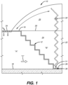
- a self actuating flood guard indicated generally by reference numeral 10 comprises a buoyant flight of steps 12, having a lower end 14 and an upper end 16, that bridges a vertical distance between lower level 18 and upper level 20 of a construction 22.
- the flight of steps 12 is flanked by vertical walls 24, 24' alongside flight 12 below level 20 and vertical walls 25, 25' above level 20.
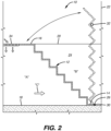
- Fig. 2 is a cross section between walls 24, 24' and 25, 25' so only walls 24 and 25 are seen.
- An inlet 34 on upper level 20 of construction 22 preceding flight 12 admits waters entering upper level 20 into lower level 18 under flight 12.
- the steps of flight 12 block fluid communication across the flight, that is, from one side "A" of the flight to the opposite side "B" of the flight.
- Pivotation members 26 located at lower end 14 of flight 12 adjacent lower level 18 of construction 22 comprise a stationary member connected to construction 22 and a moveable member moveable joined to the stationary member.
- the moveable member is connected to lower end 14 of flight 12 and is pivotable about a horizontal axis 30 transverse to the flanking vertical walls 24, 24', whereby upon presence of water at upper level 20 entering lower level 18 though inlet 34, water present under flight 12 (indicated by arrow "C") effective to buoy flight 12 upwardly, the upper end 16 of flight 12 rotates upwardly away from lower level 18, rising above upper level 20 of the construction.
- the early part of the upward rotation is effected by buoyancy lifting the flight off level 18, and the later part of rotation is driven more by hydrostatic force of water impressed against the underside of flight 12.
- a restraint 32 is affixed to construction 22 situated to act on flight 12 to prevent flight 12 from rotating about axis 30 more than a predetermined extent when upper end 16 of flight 12 rotates upwardly away from lower level 18 of construction 22.
- restraint 32 is connected to construction 22 a distance above lower end 14 of flight 12 allowing the flight to rotate to a substantially vertical orientation.
- restraint 32 is located above upper level 20 substantially in a vertical plane in which axis 30 also resides, but restraint 32 may be located below level 20, and need not reside in such vertical plane.
- a self actuating flood guard indicated generally by reference numeral 10' comprises a buoyant flight of steps 12, having a lower end 14 and an upper end 16, that bridges a vertical distance between lower level 18 and upper level 20 of a multi-level construction 22.
- the flight of steps 12 is flanked by vertical walls 24, 24' alongside flight 12.
- Fig. 2 is a cross section between walls 24, 24' so only one of the walls, wall 24, is seen.
- Vertical walls 24, 24' extend above lower level 18 and upper level 20 in the multi-level construction 22.
- An inlet 34 on upper level 20 of construction 22 preceding flight 12 admits waters entering upper level 20 into lower level 18 under flight 12.
- Pivotation members 26 located at lower end 14 of flight 12 adjacent lower level 18 of construction 22 comprise a stationary member connected to construction 22 and a moveable member moveable joined to the stationary member.
- the moveable member is connected to lower end 14 of flight 12 and is pivotable about a horizontal axis 30 transverse to the flanking vertical walls 24, 24', whereby upon presence of water under flight 12 (indicated by arrow "C") effective to buoy flight 12 upwardly, the upper end 16 of flight 12 rotates upwardly away from lower level 18, rising above upper level 20 of the construction.
- a restraint 32 is affixed to construction 22 situated to act on flight 12 to prevent flight 12 from rotating about axis 30 more than a predetermined extent when upper end 16 of flight 12 rotates upwardly away from lower level 18 of construction 22. Restraint 32 is connected to construction 22 a distance above lower end 14 of flight 12 allowing the flight to rotate to a substantially vertical orientation. As shown in the embodiment of Fig. 2 , restraint 32 is located above upper level 20 substantially in a vertical plane in which axis 30 also resides, but restraint 32 may be located below level 20, and need not reside in such vertical plane.
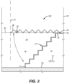
- a self actuating flood guard indicated generally by reference numeral 100 comprises a buoyant flight of steps 12 having a lower end 14 and an upper end 16 and bridges a vertical distance between lower level 18 and upper level 20 of a multi-level construction 22.
- the flight of steps 12 is flanked by vertical walls 24, 24' alongside flight 12. Vertical walls 24, 24' extend at least above lower level 18 to upper level 20.
- Fig. 3 is a cross section between walls 24, 24' so only one of the walls, wall 24, is seen.
- the steps of flight 12 block fluid communication across the flight, that is, from one side "A" of the flight to the opposite side "B" of the flight.
- Pivotation members 26 located at upper end 16 of flight 12 adjacent upper level 20 of construction 22 comprise a stationary member connected to construction 22 and a moveable member moveable joined to the stationary member.
- the moveable member is connected to upper end 16 of flight 12 and is pivotable about a horizontal axis 30 transverse to the flanking vertical walls 24, 24', whereby upon entry of water onto level 18 (indicated by exemplary arrow "C") effective to buoy flight 12, the lower end 14 of flight 12 buoyantly rotates upwardly away from lower level 18 of construction 22.
- a restraint 32 is affixed to construction 22 situated to act on flight 12 to prevent flight 12 from rotating about axis 30 more than a predetermined extent when lower end 14 of flight 12 buoyantly rotates upwardly away from lower level 18 of construction 22.
- restraint 32 is connected to construction 22 a distance above lower end 14 of flight 12 allowing the flight to rotate to a substantially horizontal orientation.
- construction 22 depicted in Fig. 3 comprises a stairwell in which the flight of stars 12 is placed and in which the stairwell includes a wall 27 (indicated by dashed lines) transverse to flanking walls 24, 24', which extend above level 20.
- Wall 27 is spaced from axis 30 by a distance sufficiently equal to the run of flight 12 that on rotation of flight 12 to substantially horizontal orientation, water in lower level 18 is blocked from entering upper level 20.
- restraint 32 is connected to construction 22 a distance above lower level 18 allowing flight 12 to rotate at least to a substantially vertical orientation, as in Fig. 2 , such that water is blocked from entering a portion of upper level 20, for example, a hallway, past the vertically rotated flight 12.
- flexible lip seal gaskets along lateral sides of flight 12 have width sufficient to sealingly wipe flanking walls 24, 24' and prevent significant passage of water between the lateral sides of flight 12 and flanking walls 24, 24'.
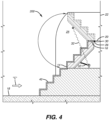
- FIG. 4 another embodiment 200, is depicted. It guards an upper level (or floor) of a construction from flood waters rising from a lower level to the upper level of a construction in which steps lead from the lower level (for example, but not limited to, ground level) to the upper level (which might be the first floor or ground floor of a building) where but for the flood guard the rising waters would flood the upper level.
- the same reference numerals employed in Figs. 1 -3 are used to indicate corresponding members.
- Construction 22 above level 20 may be an entrance of a building.
- Pivotation members 26 are located at an upper end 16 of 12 flight adjacent upper level 20 of construction 22. The lower end 14 of a flight 12 rests on stationary stairs 40.
- Flight 12 and stationary stairs 40 span upper and lower levels 18 and 20 respectively and provide access from lower level 18, which may be at ground level, to upper level 20, suitably into an entrance of a building construction 22 fronted by the stairs.
- end 14 of flight 12 remote from axis 30 rotates upwardly away from stationary stairs 40 on lower level 18.
- a restraint 32 is connected both to construction 22 a distance above lower level 18 and to flight 12, allowing flight 12 to rotate to a substantially vertical orientation wiping walls 25, 25' during rotation such that water is blocked from entering upper level 20 past rotated flight 12 (extended restraint 32 shown in dashed lines).
- Figs. 1-3 Fig.
- FIG. 4 is a cross section between walls 25, 25' so only one of the walls, wall 25, is seen.
- flexible lip seal gaskets (not seen in this schematic cross section) along lateral sides of flight 12 have width sufficient to sealingly wipe flanking walls 25, 25' and prevent significant passage of water between the lateral sides of flight 12 and flanking walls 25, 25'.
- construction 22 for example, a multi-level building, is guarded from flooding from a different level (18 or 20) of construction 22 accessed by stairs, by a method comprising providing a buoyant flight of steps having an lower end 14 and an upper end 16 and bridging at least an upper part of a vertical distance between lower level 18 and upper level 20 of building 22, flight 12 being flanked by vertical walls 24, 24' alongside flight 12, the steps in flight 22 blocking fluid communication across the flight; additionally providing pivotation members 26 comprising a stationary member connected to construction 22 adjacent one of the levels (18 or 20) and a moveable member moveably joined to the stationary member, the moveable member being connected to one of the ends (14 or 16) of flight 12 and pivotable about a horizontal axis 30 transverse to vertical walls 24, 24', whereby upon presence of water in one of the levels 18 or 20, effective to buoy flight 12, an end (14 or 16) of the flight 12 remote from axis 30 rotates upwardly away from lower level 18 of construction 22; and further providing at least one restraint 32 configured
Landscapes
- Engineering & Computer Science (AREA)
- Architecture (AREA)
- Civil Engineering (AREA)
- Structural Engineering (AREA)
- Business, Economics & Management (AREA)
- Emergency Management (AREA)
- Environmental & Geological Engineering (AREA)
- Revetment (AREA)
- Barrages (AREA)
- Buildings Adapted To Withstand Abnormal External Influences (AREA)
Claims (15)
- Ein selbsttätiger Überschwemmungsschutz, umfassend:einen auftriebsfähigen Gang (12) von Stufen, der ein unteres (14) und ein oberes (16) Ende aufweist und mindestens einen oberen Teil von einem vertikalen Abstand zwischen einer unteren und oberen Etage eines Bauwerks überbrückt, wobei der genannte Gang (12) von vertikalen Wänden entlang des Gangs flankiert ist, wobei die genannten Stufen in dem genannten Gang eine Flüssigkeitskommunikation am Gang blockieren,Schwenkglieder (26), umfassend ein stationäres Glied, das mit dem genannten Bauwerk neben einer der genannten Etagen verbunden ist, und ein bewegbares Glied das mit dem genannten stationären Glied bewegbar zusammengefügt ist, wobei das genannte bewegbare Glied mit einem (14 oder 16) der genannten Enden des genannten Gangs (12) verbunden ist und um eine horizontale Achse (30) quer zu den genannten vertikalen Wänden schwenkbar ist, wodurch es in Gegenwart von Wasser an einer der genannten Etagen wirksam ist, um den genannten Gang aufzutreiben, wobei ein von der genannten Achse (30) entferntes Ende (16) des Gangs (12) von der genannten unteren Etage des Bauwerks weg aufwärts rotiert, undmindestens eine Rückhaltung (32), die dazu konfiguriert ist, zu verhindern, dass der Gang (12) um die genannte Achse um mehr als ein vorherbestimmtes Maß rotiert, wenn das von der genannten Achse entfernte genannte Ende des genannten Gangs (12) von der genannten unteren Etage des Bauwerks weg aufwärts rotiert, wobei die mindestens eine Rückhaltung (32) dazu konfiguriert ist, dem Gang (12) zu ermöglichen, um die genannte Achse in eine im Wesentlichen vertikale Orientierung zu rotieren.
- Überschwemmungsschutz nach Anspruch 1, bei dem die genannte Rückhaltung (32) mit dem Bauwerk in einem Abstand über dem genannten unteren Ende des genannten Gangs verbunden ist.
- Überschwemmungsschutz nach Anspruch 1, ferner umfassend flexible Lippenabdichtungen entlang lateraler Seiten des Gangs (12) mit einer Breite, die ausreicht, um die genannten flankierenden Wände abdichtend zu streifen und einen wesentlichen Durchtritt von Wasser zwischen den lateralen Seiten des Gangs zu verhindern und einen wesentlichen Durchtritt von Wasser zwischen den lateralen Seiten des Gangs und den flankierenden Wänden zu verhindern.
- Überschwemmungsschutz nach Anspruch 1, bei dem die genannten Schwenkglieder (26) an dem genannten unteren Ende (14) des genannten Gangs (12) neben der unteren Etage des Bauwerks liegen.
- Überschwemmungsschutz nach Anspruch 4, umfassend einen Eintritt auf der genannten oberen Etage, um in die genannte obere Etage eindringendes Wasser in die genannte untere Etage einzulassen.
- Überschwemmungsschutz nach Anspruch 4, bei dem die genannte Rückhaltung mit dem Bauwerk in einem Abstand über der genannten horizontalen Achse verbunden ist, wodurch dem Gang ermöglicht wird, in eine im Wesentlichen vertikale Orientierung zu rotieren.
- Überschwemmungsschutz nach Anspruch 1, bei dem die genannten Schwenkglieder am genannten oberen Ende des genannten Gangs neben der genannten oberen Etage liegen.
- Überschwemmungsschutz nach Anspruch 7, bei dem die genannte Rückhaltung mit dem Bauwerk in einem Abstand über der genannten unteren Etage verbunden ist, wodurch dem Gang ermöglicht wird, mindestens in eine im Wesentlichen horizontale Orientierung zu rotieren.
- Überschwemmungsschutz nach Anspruch 8, bei dem das genannte Bauwerk ein Treppenhaus umfasst, in dem der genannte Treppengang platziert ist und bei dem das genannte Treppenhaus eine Wand quer zu den genannten flankierenden Wänden und von der genannten Achse in einem Abstand beabstandet beinhaltet, der einem Lauf des Gangs plus der Trittfläche der letzten Stufe des Gangs ausreichend gleicht, sodass bei Rotation des Gangs in die genannte im Wesentlichen horizontale Orientierung ein Eindringen von Wasser unter dem genannten Gang in die genannte obere Etage blockiert wird.
- Überschwemmungsschutz nach Anspruch 7, bei dem die genannte Rückhaltung mit dem Bauwerk in einem Abstand über der genannten oberen Etage verbunden ist, wodurch dem Gang ermöglicht wird, mindestens in eine im Wesentlichen vertikale Orientierung zu rotieren, sodass ein Eindringen von Wasser in die genannte obere Etage an dem genannten rotierten Gang vorbei blockiert wird.
- Überschwemmungsschutz nach Anspruch 7, bei dem das genannte untere Ende des genannten Gangs auf stationären Treppenstufen aufliegt, wobei der genannte Gang und die genannten stationären Treppenstufen die genannte obere und untere Etage überspannen.
- Überschwemmungsschutz nach Anspruch 11, bei dem die genannte Rückhaltung mit dem Bauwerk in einem Abstand über der genannten unteren Etage und mit dem genannten Gang verbunden ist, wodurch dem Gang ermöglicht wird, mindestens in eine im Wesentlichen vertikale Orientierung zu rotieren, sodass ein Eindringen von Wasser in die genannte obere Etage an dem genannten rotierten Gang vorbei blockiert wird.
- Ein Verfahren zum Schützen einer Etage eines Mehretagenbauwerks vor Überschwemmung durch Wasser von einer anderen Etage des Bauwerks, bei dem die Etagen durch Verbindungstreppen erreicht werden, umfassend:Bereitstellen eines auftriebsfähigen Gangs von Stufen, der ein unteres und ein oberes Ende aufweist und mindestens einen oberen Teil von einem vertikalen Abstand zwischen einer unteren und oberen Etage eines genannten Gebäudes überbrückt und von vertikalen Wänden entlang des Gangs flankiert ist, wobei die genannten Stufen in dem genannten Gang eine Flüssigkeitskommunikation am Gang blockieren,Bereitstellen von Schwenkgliedern, umfassend ein stationäres Glied, das mit dem genannten Bauwerk neben einer der genannten Etagen verbunden ist, und ein bewegbares Glied das mit dem genannten stationären Glied bewegbar zusammengefügt ist, wobei das genannte bewegbare Glied mit einem der genannten Enden des genannten Gangs verbunden ist und um eine horizontale Achse quer zu den genannten vertikalen Wänden schwenkbar ist, wodurch es in Gegenwart von Wasser in einer der genannten Etagen wirksam ist, um den genannten Gang aufzutreiben, wobei ein von der genannten Achse entferntes Ende des Gangs von der genannten unteren Etage des Bauwerks weg aufwärts rotiert, undBereitstellen von mindestens einer Rückhaltung, die dazu konfiguriert ist, zu verhindern, dass der Gang um die genannte Achse um mehr als ein vorherbestimmtes Maß rotiert, wenn das von der genannten Achse entfernte genannte Ende des genannten Gangs von der genannten unteren Etage des Bauwerks weg aufwärts rotiert, wobei die mindestens eine Rückhaltung (32) dazu konfiguriert ist, dem Gang (12) zu ermöglichen, um die genannte Achse in eine im Wesentlichen vertikale Orientierung zu rotieren.
- Verfahren nach Anspruch 13, bei dem die genannten Schwenkglieder an dem genannten unteren Ende des genannten Gangs neben der unteren Etage des Bauwerks liegen.
- Verfahren nach Anspruch 13, bei dem die genannten Schwenkglieder an dem genannten oberen Ende des genannten Gangs neben der oberen Etage des Bauwerks liegen.
Applications Claiming Priority (2)
| Application Number | Priority Date | Filing Date | Title |
|---|---|---|---|
| US201562250923P | 2015-11-04 | 2015-11-04 | |
| PCT/IB2016/001754 WO2017077396A1 (en) | 2015-11-04 | 2016-10-29 | Self-actuating flood guard |
Publications (4)
| Publication Number | Publication Date |
|---|---|
| EP3371377A1 EP3371377A1 (de) | 2018-09-12 |
| EP3371377A4 EP3371377A4 (de) | 2019-06-19 |
| EP3371377C0 EP3371377C0 (de) | 2024-09-25 |
| EP3371377B1 true EP3371377B1 (de) | 2024-09-25 |
Family
ID=58661678
Family Applications (1)
| Application Number | Title | Priority Date | Filing Date |
|---|---|---|---|
| EP16861686.0A Active EP3371377B1 (de) | 2015-11-04 | 2016-10-29 | Selbsteinschaltender überschwemmungsschutz |
Country Status (4)
| Country | Link |
|---|---|
| US (1) | US10202772B2 (de) |
| EP (1) | EP3371377B1 (de) |
| JP (1) | JP2018538467A (de) |
| WO (1) | WO2017077396A1 (de) |
Families Citing this family (1)
| Publication number | Priority date | Publication date | Assignee | Title |
|---|---|---|---|---|
| JP6712711B1 (ja) * | 2020-02-02 | 2020-06-24 | 株式会社くまい建築設計 | 階段装置 |
Citations (1)
| Publication number | Priority date | Publication date | Assignee | Title |
|---|---|---|---|---|
| JP2005351057A (ja) * | 2004-06-08 | 2005-12-22 | Fukui Tekko Kk | 都市地下施設もしくは地下鉄への流入水及び浸水の防止装置 |
Family Cites Families (16)
| Publication number | Priority date | Publication date | Assignee | Title |
|---|---|---|---|---|
| GB191211669A (en) | 1912-05-16 | 1913-05-16 | Robert Blake Mcvittie | Improvements in or relating to Ships and similar Structures. |
| US3731761A (en) * | 1971-08-19 | 1973-05-08 | R Glenn | Floating pier with self adjusting stairway assembly |
| ES210608Y (es) | 1975-03-08 | 1976-10-01 | Hernandez Gonzalez | Pasarela-escala para atraque de embarcaciones. |
| US4377352A (en) | 1981-01-02 | 1983-03-22 | Goodstein Charles B | Self-actuating water containment barrier |
| US5657832A (en) * | 1996-02-28 | 1997-08-19 | Stevens; Robert C. | Stairway for connecting a floating member to a stationary member |
| JP3542537B2 (ja) * | 2000-02-02 | 2004-07-14 | 日本エフ・アール・ピー株式会社 | 建造物出入口の流入水遮断用フローゲートのロック装置 |
| JP4558242B2 (ja) * | 2001-07-18 | 2010-10-06 | 株式会社 Fmバルブ製作所 | フロート形防水装置 |
| US6845845B2 (en) * | 2002-03-13 | 2005-01-25 | Jsv Group Inc. | Water recreation dock |
| US6623209B1 (en) | 2002-04-04 | 2003-09-23 | Floodbreak Llc | Automatic flood gate |
| US7159261B2 (en) * | 2004-04-05 | 2007-01-09 | Carrigan Stephen A | Convertible dock ramp |
| JP2007002641A (ja) | 2005-06-23 | 2007-01-11 | Sugawa Actuator Kk | 地下階段入口の洪水流入水防止装置 |
| FR2926095A1 (fr) | 2008-01-03 | 2009-07-10 | Gerard Orriere | Digue comprenant un socle sur lequel est articulee une barriere qui est manoeuvrable en pivotement par un flotteur |
| GB201108312D0 (en) | 2011-05-18 | 2011-06-29 | Brindley Charles S | Self-raising flood protection barrier |
| US20120148346A1 (en) * | 2012-03-01 | 2012-06-14 | Shahriar Eftekharzadeh | Self-deploying floodwall |
| JP5931580B2 (ja) | 2012-05-17 | 2016-06-08 | 開成工業株式会社 | 浮体式陸閘ゲート |
| JP5988319B2 (ja) * | 2015-01-26 | 2016-09-07 | 隆美 角田 | 陸閘 |
-
2016
- 2016-10-29 US US15/771,175 patent/US10202772B2/en active Active
- 2016-10-29 WO PCT/IB2016/001754 patent/WO2017077396A1/en not_active Ceased
- 2016-10-29 EP EP16861686.0A patent/EP3371377B1/de active Active
- 2016-10-29 JP JP2018541584A patent/JP2018538467A/ja active Pending
Patent Citations (1)
| Publication number | Priority date | Publication date | Assignee | Title |
|---|---|---|---|---|
| JP2005351057A (ja) * | 2004-06-08 | 2005-12-22 | Fukui Tekko Kk | 都市地下施設もしくは地下鉄への流入水及び浸水の防止装置 |
Also Published As
| Publication number | Publication date |
|---|---|
| US20180305933A1 (en) | 2018-10-25 |
| JP2018538467A (ja) | 2018-12-27 |
| EP3371377C0 (de) | 2024-09-25 |
| US10202772B2 (en) | 2019-02-12 |
| EP3371377A1 (de) | 2018-09-12 |
| EP3371377A4 (de) | 2019-06-19 |
| WO2017077396A1 (en) | 2017-05-11 |
Similar Documents
| Publication | Publication Date | Title |
|---|---|---|
| KR102282034B1 (ko) | 리프트형 홍수 방어벽 | |
| US10072436B2 (en) | Self-actuating flood guard | |
| EP2601354B1 (de) | Verfahren zur Montage eines selbsteinschaltenden Überschwemmungsschutzes | |
| KR101482726B1 (ko) | 차수문의 개폐시스템 | |
| KR101210580B1 (ko) | 슬라이드식 방조제 방수문 | |
| EP3371377B1 (de) | Selbsteinschaltender überschwemmungsschutz | |
| KR20150119794A (ko) | 육상형 플랩 게이트 | |
| KR101351837B1 (ko) | 지하도 출입구의 물막이 장치 | |
| KR101455186B1 (ko) | 침수방지용 홍수벽 | |
| JP3770554B2 (ja) | 水防用のウオータゲート装置 | |
| CN104074172B (zh) | 水利闸站闸门升降定位止水装置 | |
| GB2323621A (en) | Self-actuating flood barrier | |
| JP2001032621A (ja) | 防水扉 | |
| KR101199472B1 (ko) | 방호벽용 방수문 | |
| JP5988319B2 (ja) | 陸閘 | |
| JP2016029241A (ja) | 溢水防止装置 | |
| KR102756085B1 (ko) | 침수 방지장치와 침수 대피구조를 구비한 지하차도 구조체 | |
| KR20220034999A (ko) | 터널과 지하차도의 침수에 따른 사고 방지 출입통제기 | |
| WO2003042459A1 (fr) | Systeme de controle de marees a commande hydraulique | |
| KR101468533B1 (ko) | 해양작업지원선의 문풀 리세스 도어 | |
| KR102792784B1 (ko) | 침수 예방 지하차도 | |
| KR102883850B1 (ko) | 승강식 차수장치 | |
| KR102808366B1 (ko) | 승강개폐형 차수장치 | |
| JP5661390B2 (ja) | 可動式ゲート装置 | |
| JP6347403B2 (ja) | 横スリットの止水装置及び縦スリットの止水装置 |
Legal Events
| Date | Code | Title | Description |
|---|---|---|---|
| STAA | Information on the status of an ep patent application or granted ep patent |
Free format text: STATUS: THE INTERNATIONAL PUBLICATION HAS BEEN MADE |
|
| PUAI | Public reference made under article 153(3) epc to a published international application that has entered the european phase |
Free format text: ORIGINAL CODE: 0009012 |
|
| STAA | Information on the status of an ep patent application or granted ep patent |
Free format text: STATUS: REQUEST FOR EXAMINATION WAS MADE |
|
| 17P | Request for examination filed |
Effective date: 20180524 |
|
| AK | Designated contracting states |
Kind code of ref document: A1 Designated state(s): AL AT BE BG CH CY CZ DE DK EE ES FI FR GB GR HR HU IE IS IT LI LT LU LV MC MK MT NL NO PL PT RO RS SE SI SK SM TR |
|
| AX | Request for extension of the european patent |
Extension state: BA ME |
|
| DAV | Request for validation of the european patent (deleted) | ||
| DAX | Request for extension of the european patent (deleted) | ||
| A4 | Supplementary search report drawn up and despatched |
Effective date: 20190521 |
|
| RIC1 | Information provided on ipc code assigned before grant |
Ipc: E04F 11/00 20060101ALI20190515BHEP Ipc: E02B 3/10 20060101ALI20190515BHEP Ipc: E02B 7/40 20060101ALI20190515BHEP Ipc: E04H 9/14 20060101ALI20190515BHEP Ipc: E04F 11/02 20060101ALI20190515BHEP Ipc: E02B 7/20 20060101AFI20190515BHEP Ipc: E06B 5/00 20060101ALI20190515BHEP Ipc: E02B 7/50 20060101ALI20190515BHEP |
|
| RAP1 | Party data changed (applicant data changed or rights of an application transferred) |
Owner name: FLOODBREAK, L.L.C. |
|
| RIN1 | Information on inventor provided before grant (corrected) |
Inventor name: WATERS, LOUIS, A., JR. |
|
| RIN1 | Information on inventor provided before grant (corrected) |
Inventor name: WATERS, LOUIS, A., JR. |
|
| STAA | Information on the status of an ep patent application or granted ep patent |
Free format text: STATUS: EXAMINATION IS IN PROGRESS |
|
| 17Q | First examination report despatched |
Effective date: 20220209 |
|
| RIN1 | Information on inventor provided before grant (corrected) |
Inventor name: WATERS, LOUIS A., JR. |
|
| GRAP | Despatch of communication of intention to grant a patent |
Free format text: ORIGINAL CODE: EPIDOSNIGR1 |
|
| STAA | Information on the status of an ep patent application or granted ep patent |
Free format text: STATUS: GRANT OF PATENT IS INTENDED |
|
| INTG | Intention to grant announced |
Effective date: 20240315 |
|
| GRAJ | Information related to disapproval of communication of intention to grant by the applicant or resumption of examination proceedings by the epo deleted |
Free format text: ORIGINAL CODE: EPIDOSDIGR1 |
|
| STAA | Information on the status of an ep patent application or granted ep patent |
Free format text: STATUS: EXAMINATION IS IN PROGRESS |
|
| GRAP | Despatch of communication of intention to grant a patent |
Free format text: ORIGINAL CODE: EPIDOSNIGR1 |
|
| STAA | Information on the status of an ep patent application or granted ep patent |
Free format text: STATUS: GRANT OF PATENT IS INTENDED |
|
| INTC | Intention to grant announced (deleted) | ||
| INTG | Intention to grant announced |
Effective date: 20240610 |
|
| GRAS | Grant fee paid |
Free format text: ORIGINAL CODE: EPIDOSNIGR3 |
|
| GRAA | (expected) grant |
Free format text: ORIGINAL CODE: 0009210 |
|
| STAA | Information on the status of an ep patent application or granted ep patent |
Free format text: STATUS: THE PATENT HAS BEEN GRANTED |
|
| AK | Designated contracting states |
Kind code of ref document: B1 Designated state(s): AL AT BE BG CH CY CZ DE DK EE ES FI FR GB GR HR HU IE IS IT LI LT LU LV MC MK MT NL NO PL PT RO RS SE SI SK SM TR |
|
| REG | Reference to a national code |
Ref country code: GB Ref legal event code: FG4D |
|
| REG | Reference to a national code |
Ref country code: CH Ref legal event code: EP |
|
| REG | Reference to a national code |
Ref country code: DE Ref legal event code: R096 Ref document number: 602016089595 Country of ref document: DE |
|
| REG | Reference to a national code |
Ref country code: IE Ref legal event code: FG4D |
|
| U01 | Request for unitary effect filed |
Effective date: 20241014 |
|
| U07 | Unitary effect registered |
Designated state(s): AT BE BG DE DK EE FI FR IT LT LU LV MT NL PT RO SE SI Effective date: 20241030 |
|
| U20 | Renewal fee for the european patent with unitary effect paid |
Year of fee payment: 9 Effective date: 20241128 |
|
| PG25 | Lapsed in a contracting state [announced via postgrant information from national office to epo] |
Ref country code: NO Free format text: LAPSE BECAUSE OF FAILURE TO SUBMIT A TRANSLATION OF THE DESCRIPTION OR TO PAY THE FEE WITHIN THE PRESCRIBED TIME-LIMIT Effective date: 20241225 |
|
| PG25 | Lapsed in a contracting state [announced via postgrant information from national office to epo] |
Ref country code: GR Free format text: LAPSE BECAUSE OF FAILURE TO SUBMIT A TRANSLATION OF THE DESCRIPTION OR TO PAY THE FEE WITHIN THE PRESCRIBED TIME-LIMIT Effective date: 20241226 |
|
| PG25 | Lapsed in a contracting state [announced via postgrant information from national office to epo] |
Ref country code: RS Free format text: LAPSE BECAUSE OF FAILURE TO SUBMIT A TRANSLATION OF THE DESCRIPTION OR TO PAY THE FEE WITHIN THE PRESCRIBED TIME-LIMIT Effective date: 20241225 |
|
| PG25 | Lapsed in a contracting state [announced via postgrant information from national office to epo] |
Ref country code: RS Free format text: LAPSE BECAUSE OF FAILURE TO SUBMIT A TRANSLATION OF THE DESCRIPTION OR TO PAY THE FEE WITHIN THE PRESCRIBED TIME-LIMIT Effective date: 20241225 Ref country code: NO Free format text: LAPSE BECAUSE OF FAILURE TO SUBMIT A TRANSLATION OF THE DESCRIPTION OR TO PAY THE FEE WITHIN THE PRESCRIBED TIME-LIMIT Effective date: 20241225 Ref country code: GR Free format text: LAPSE BECAUSE OF FAILURE TO SUBMIT A TRANSLATION OF THE DESCRIPTION OR TO PAY THE FEE WITHIN THE PRESCRIBED TIME-LIMIT Effective date: 20241226 |
|
| PG25 | Lapsed in a contracting state [announced via postgrant information from national office to epo] |
Ref country code: IS Free format text: LAPSE BECAUSE OF FAILURE TO SUBMIT A TRANSLATION OF THE DESCRIPTION OR TO PAY THE FEE WITHIN THE PRESCRIBED TIME-LIMIT Effective date: 20250125 |
|
| PG25 | Lapsed in a contracting state [announced via postgrant information from national office to epo] |
Ref country code: SM Free format text: LAPSE BECAUSE OF FAILURE TO SUBMIT A TRANSLATION OF THE DESCRIPTION OR TO PAY THE FEE WITHIN THE PRESCRIBED TIME-LIMIT Effective date: 20240925 |
|
| PG25 | Lapsed in a contracting state [announced via postgrant information from national office to epo] |
Ref country code: ES Free format text: LAPSE BECAUSE OF FAILURE TO SUBMIT A TRANSLATION OF THE DESCRIPTION OR TO PAY THE FEE WITHIN THE PRESCRIBED TIME-LIMIT Effective date: 20240925 |
|
| PG25 | Lapsed in a contracting state [announced via postgrant information from national office to epo] |
Ref country code: CZ Free format text: LAPSE BECAUSE OF FAILURE TO SUBMIT A TRANSLATION OF THE DESCRIPTION OR TO PAY THE FEE WITHIN THE PRESCRIBED TIME-LIMIT Effective date: 20240925 Ref country code: PL Free format text: LAPSE BECAUSE OF FAILURE TO SUBMIT A TRANSLATION OF THE DESCRIPTION OR TO PAY THE FEE WITHIN THE PRESCRIBED TIME-LIMIT Effective date: 20240925 |
|
| PG25 | Lapsed in a contracting state [announced via postgrant information from national office to epo] |
Ref country code: SK Free format text: LAPSE BECAUSE OF FAILURE TO SUBMIT A TRANSLATION OF THE DESCRIPTION OR TO PAY THE FEE WITHIN THE PRESCRIBED TIME-LIMIT Effective date: 20240925 |
|
| REG | Reference to a national code |
Ref country code: CH Ref legal event code: PL |
|
| PG25 | Lapsed in a contracting state [announced via postgrant information from national office to epo] |
Ref country code: MC Free format text: LAPSE BECAUSE OF FAILURE TO SUBMIT A TRANSLATION OF THE DESCRIPTION OR TO PAY THE FEE WITHIN THE PRESCRIBED TIME-LIMIT Effective date: 20240925 |
|
| PG25 | Lapsed in a contracting state [announced via postgrant information from national office to epo] |
Ref country code: CH Free format text: LAPSE BECAUSE OF NON-PAYMENT OF DUE FEES Effective date: 20241031 |
|
| PLBE | No opposition filed within time limit |
Free format text: ORIGINAL CODE: 0009261 |
|
| STAA | Information on the status of an ep patent application or granted ep patent |
Free format text: STATUS: NO OPPOSITION FILED WITHIN TIME LIMIT |
|
| 26N | No opposition filed |
Effective date: 20250626 |
|
| PG25 | Lapsed in a contracting state [announced via postgrant information from national office to epo] |
Ref country code: IE Free format text: LAPSE BECAUSE OF NON-PAYMENT OF DUE FEES Effective date: 20241029 |
|
| U20 | Renewal fee for the european patent with unitary effect paid |
Year of fee payment: 10 Effective date: 20251015 |
|
| PGFP | Annual fee paid to national office [announced via postgrant information from national office to epo] |
Ref country code: GB Payment date: 20251016 Year of fee payment: 10 |
|
| PG25 | Lapsed in a contracting state [announced via postgrant information from national office to epo] |
Ref country code: HR Free format text: LAPSE BECAUSE OF FAILURE TO SUBMIT A TRANSLATION OF THE DESCRIPTION OR TO PAY THE FEE WITHIN THE PRESCRIBED TIME-LIMIT Effective date: 20240925 |
|
| PG25 | Lapsed in a contracting state [announced via postgrant information from national office to epo] |
Ref country code: HU Free format text: LAPSE BECAUSE OF FAILURE TO SUBMIT A TRANSLATION OF THE DESCRIPTION OR TO PAY THE FEE WITHIN THE PRESCRIBED TIME-LIMIT; INVALID AB INITIO Effective date: 20161029 |
|
| PG25 | Lapsed in a contracting state [announced via postgrant information from national office to epo] |
Ref country code: CY Free format text: LAPSE BECAUSE OF FAILURE TO SUBMIT A TRANSLATION OF THE DESCRIPTION OR TO PAY THE FEE WITHIN THE PRESCRIBED TIME-LIMIT; INVALID AB INITIO Effective date: 20161029 |