EP3368708B1 - Spindel mit einer trennvorrichtung - Google Patents
Spindel mit einer trennvorrichtung Download PDFInfo
- Publication number
- EP3368708B1 EP3368708B1 EP16788239.8A EP16788239A EP3368708B1 EP 3368708 B1 EP3368708 B1 EP 3368708B1 EP 16788239 A EP16788239 A EP 16788239A EP 3368708 B1 EP3368708 B1 EP 3368708B1
- Authority
- EP
- European Patent Office
- Prior art keywords
- spindle
- area
- clamping
- severing
- separating device
- Prior art date
- Legal status (The legal status is an assumption and is not a legal conclusion. Google has not performed a legal analysis and makes no representation as to the accuracy of the status listed.)
- Active
Links
Images


Classifications
-
- D—TEXTILES; PAPER
- D01—NATURAL OR MAN-MADE THREADS OR FIBRES; SPINNING
- D01H—SPINNING OR TWISTING
- D01H9/00—Arrangements for replacing or removing bobbins, cores, receptacles, or completed packages at paying-out or take-up stations ; Combination of spinning-winding machine
- D01H9/02—Arrangements for replacing or removing bobbins, cores, receptacles, or completed packages at paying-out or take-up stations ; Combination of spinning-winding machine for removing completed take-up packages and replacing by bobbins, cores, or receptacles at take-up stations; Transferring material between adjacent full and empty take-up elements
- D01H9/16—Yarn-severing arrangements, e.g. for cutting transfer tails; Separating of roving in flyer
Definitions
- the present invention relates to a spindle for a work station of a textile machine, in particular a ring spinning machine, according to the independent claim.
- the invention also relates to a separating device and a ring spinning machine with a plurality of work stations.
- Ring spinning spindles with a separating device for separating a spun yarn when a cop is pulled off are well known, for example from EP 911 434 B1 .
- the separating device is guided with a collar on the upper part of the spindle and fixed on the upper part of the spindle with a lug that falls behind a groove in the upper part of the spindle.
- this form of attachment requires a groove in the spindle upper part, which is known to have only a few special spindles. This separating device cannot be used for all other spindles.
- EP0292856A1 shows a top ring with a split area and a flange. This ring is disadvantageously attached to an upper end of the spindle base of the spindle, making the shank disadvantageously difficult to detach. A simple replacement of the cutting ring is not possible due to the attachment. The risk of injury for the operator is also relatively high due to the protruding teeth.
- DE2215251A1 discloses a ring with teeth and a slot that fits over a lower portion of a spool.
- the disadvantage is that the ring sits on the spool, ie each spool has to be equipped with it, which is a not inconsiderable cost factor.
- there is still a great risk of injury since the bobbins are frequently changed by the operator and the teeth can injure him when touching them.
- EP0458088A1 relates to a thread separating device for a spindle of a spinning or twisting machine with an annular body which sits between a sleeve receptacle of the spindle and a winding point of the spindle used to fix a spun thread and which has an edge protruding from the spindle in the radial direction, which has several acute-angled is provided with inwardly tapering notches, the edges of which are designed as cutting edges.
- the attachment to the shaft is done disadvantageously by a cover that is provided with internal locking lugs. Due to the protruding spikes, the risk of accidents should not be underestimated either.
- the object of the present invention is therefore to create a spindle with an associated separating device, in which case the separating device can be fastened to the shaft as simply as possible.
- the object is achieved by a spindle with a shaft and a separating device, a separating device and a ring spinning machine with a plurality of work stations, each having a spindle with a separating device, with the features of the independent claim.
- a spindle for a work station of a textile machine in particular a ring spinning machine, is proposed.
- the spindle has a shank for receiving a sleeve.
- a thread is wound onto the tube so that the tube becomes a cop.
- the spindle has a separating device. This separates the thread from the spindle when the cop is pulled off, so that the cop can be removed freely and the thread remaining on the textile machine can be wound onto a new tube.
- the separating device has a recess for enclosing the shaft so that it can lie around the shaft. An inner area adjoins this recess. Furthermore, the separating device has a separating area in which the thread is ultimately separated.
- the spindle has a spindle base adjacent to the shaft, the separating device is separate from the spindle base, ie an independent element, and the inner area of the separating device has at least one clamping area.
- the separating device is clamped to the shaft with this clamping area.
- the clamp firmly attaches the cutting device to the shaft of the spindle.
- the spindle does not need to have any special fastening device(s) since it can be clamped to a conventional shank.
- thanks to the clamp it is also easy to replace the separator, for example if it has become blunt.
- the at least one clamping area is circular.
- the diameter of the circular clamping area must be smaller than or equal to a diameter of the shank at a lower end of the shank where the separating device is usually attached. Since a circular clamping area clamps over the entire circumference of the spindle, a particularly strong attachment of the separating device is possible.
- the at least one clamping area that are not according to the invention are also possible. It is then advantageous if the diameter of a circle inscribed in the at least one clamping area, ie the largest circle that fits into the recess, is less than or equal to the diameter of the lower end of the shank. This ensures a strong clamping.
- the separating device has a slot.
- one end of the slot is arranged at the recess.
- the slit allows for greater deformation of the separating device, which in turn enables better clamping.
- a separating device not according to the invention can advantageously have a specially designed inner area which has three separate clamping areas. Clamping with these three clamping areas is also very effective. There is no need to attach a slot or it can be used in addition.
- the separating area has a circular edge, teeth and/or projections.
- the special design of the separating area can be adapted to the other features of the spindle, for example the geometry of a clamping crown, but also to the properties of the thread to be used.
- the separating device can advantageously be designed flat and rest on the spindle base. This is particularly advantageous since it is a space-saving variant.
- the circular edge, the spikes and/or projections are at least partially sharp.
- the thread can be separated even more easily with sharp elements.
- the separating device is designed in one piece. On the one hand, this enables the separating device to be produced cheaply and, on the other hand, it makes it more robust.
- the separating device is made of metal. This can be sanded without any problems, but also provides the elasticity required for clamping.
- the separating area has an outside diameter that is smaller than or equal to a diameter of the spindle base.
- the cutting area is set back behind the spindle base and the risk of injury to operating personnel, for example from cutting on sharp elements, is significantly reduced.
- the spindle base has indentations to better position the thread. It is then advantageous if the outside diameter of the separating area is greater than or equal to an inside diameter formed by the bases of the notches. Thus, the thread can come into contact with the cutting portion and be cut.
- the spindle base is a clamping crown. Shortly before the bobbin is to be removed, a few turns of the thread are wound onto the clamping crown and fixed there. If the cop is then removed from the spindle, the thread runs over the cutting area and is severed. With a corresponding design of the clamping crown, the separating device can also be clamped to this clamping crown.
- a ring spinning machine with a plurality of jobs has a spindle with a separating device for separating a thread when a cop is pulled off the spindle.
- the spindle is designed as described above.
- a separating device assigned to the spindle can be easily attached to the spindle and can also be easily replaced if it is blunt or another separating device tailored to a different thread is to be used.
- figure 1 shows a side view of a spindle 1.
- a cop 3 Adjacent to the shank 2 of the spindle 1 is a clamping crown 4 is hardly visible here, but is designed flat and rests on the clamping crown 4.
- a cutting device, a cutting knife or the like is suitable as the separating device 5, as will be described in the following exemplary embodiments.
- Figure 2a shows the clamping crown 4 in more detail, in the open state, as it is just before the cop 3 is removed from the spindle 1.
- a clamping sleeve 6 was pulled down so that an underwind area 7 is open.
- a few windings of thread are now wound onto the underwind area 7 .
- the thread runs through notches in a clamping collar 8 and also over the separating device 5.
- Figure 3a shows a top view of the flat separating device 5 on the clamping collar 8.
- the diameter of a separating area 10 of the flat separating device 5 is smaller than the outer diameter of the clamping ring 8, which is advantageous for the operating personnel for safety reasons.
- the separating area 10 is a sharp edge or the like existing on the periphery, so that a cutting knife is formed.
- the separating device 5 protrudes beyond the notches 9 of the clamping collar 8, so that a thread located in a notch 9 can be separated.
- Figure 3b shows a top view of the separating device 5.
- the separating area 10 is sharpened here in order to enable better severing of the thread.
- the recess 11, which is delimited by the inner area 12 of the separating device 5, is circular in shape here, with a diameter which is slightly smaller than a diameter of the shank at the lower end of the shank. In this case the inner portion 12 is equal to the clamping portion 13. Due to the slot 14 in the separator 5, the separator 5 flexes slightly when pushed onto the shank and clamps the separator 5 firmly onto the shank.
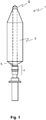
- Figure 4a shows a plan view of a further exemplary embodiment of a separating device 15.
- features which, in comparison to FIG Figure 3b illustrated first embodiment are identical and / or at least comparable in their design and / or mode of operation, the same reference numerals are used. If these are not explained again in detail, their design and/or mode of action corresponds to the design and mode of action of the features already described above.
- This separating device 15 differs in the design of the separating area 16. A large number of sharpened teeth 17 are provided here, which can reliably separate the thread.
- the slot 18 has two corners 19 . Should the thread be drawn into the slot, it will catch at the corners 19 and effectively prevent the thread from advancing to the shaft of the spindle.
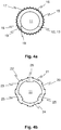
- Figure 4b shows a plan view of a separating device 20 not according to the invention.
- features that are different from those in Figure 3b illustrated first embodiment are identical and / or at least comparable in their design and / or mode of operation, the same reference numerals are used. If these are not explained again in detail, their design and/or mode of action corresponds to the design and mode of action of the features already described above.
- projections 22 are provided for the separating area 21, which are sharpened on their sides 23.
- Such projections 22 are particularly suitable for separating threads when, after the cop has been lifted slightly from the spindle, the spindle is rotated again briefly. Then the thread is pulled past a sharpened side 23 and severed.
- the separating device 20 has a specially designed inner area 24 which has three separate clamping areas 25 . Clamping with these three clamping areas 25 is also very effective and there is no need to attach a slot.
Landscapes
- Engineering & Computer Science (AREA)
- Mechanical Engineering (AREA)
- Textile Engineering (AREA)
- Spinning Or Twisting Of Yarns (AREA)
Description
- Die vorliegende Erfindung betrifft eine Spindel für eine Arbeitsstelle einer Textilmaschine, insbesondere einer Ringspinnmaschine, entsprechend dem unabhängigen Anspruch. Die Erfindung betrifft ferner eine Trennvorrichtung sowie eine Ringspinnmaschine mit einer Mehrzahl von Arbeitsstellen.
- Ringspinnspindeln mit einer Trennvorrichtung zum Trennen eines Abspinnfadens beim Abziehen eines Kopses sind wohlbekannt, beispielsweise aus der
EP 911 434 B1 -
EP0292856A1 zeigt einen oberen Ring mit einem Trennbereich und einem Flansch. Dieser Ring ist nachteilig an einem oberen Ende der Spindelbasis der Spindel befestigt, so dass sich ein Lösen des Schafts unvorteilhaft schwierig gestaltet. Ein einfaches Austauschen des Schneidringes ist durch die Befestigung gar nicht möglich. Durch die hervorstehenden Zähne ist zudem die Verletzungsgefahr für den Bediener relativ gross. -
DE2215251A1 offenbart einen Ring mit Zähnen und einem Schlitz, der über eine untere Partie einer Spule gesetzt wird. Nachteilig ist jedoch, dass der Ring auf der Spule aufsitzt, d.h. das jede Spule damit ausgestattet werden muss, was ein nicht unerheblicher Kostenfaktor ist. Zudem bleibt eine grosse Verletzungsgefahr, da die Spulen durch den Bediener häufig gewechselt werden und die Zähne ihn beim Anfassen verletzen können. -
EP0458088A1 betrifft eine Fadentrenneinrichtung für eine Spindel einer Spinn- oder Zwirnmaschine mit einem ringförmigen Körper, der zwischen einer Hülsenaufnahme der Spindel und einer zum Festlegen eines Abspinnfadens dienenden Aufwickelstelle der Spindel sitzt und der einen von der Spindel in radialer Richtung abragenden Rand aufweist, der mit mehreren spitzwinklig nach innen zulaufenden Kerben versehen ist, deren Kanten als Schneiden ausgebildet sind. Die Befestigung am Schaft geschieht unvorteilhaft durch eine Abdeckung, die mit inneren Rastnasen versehen ist. Durch die abstehenden Zacken ist hier ebenfalls die Unfallgefahr nicht zu unterschätzen. - Aufgabe der vorliegenden Erfindung ist es somit, eine Spindel mit einer dazugehörigen Trennvorrichtung zu schaffen, wobei die Trennvorrichtung möglichst einfach an dem Schaft befestigbar ist.
- Die Aufgabe wird gelöst durch eine Spindel mit einem Schaft und einer Trennvorrichtung, eine Trennvorrichtung sowie eine Ringspinnmaschine mit einer Mehrzahl von Arbeitsstellen, die jeweils eine Spindel mit einer Trennvorrichtung aufweisen, mit den Merkmalen des unabhängigen Anspruchs.
- Vorgeschlagen wird eine Spindel für eine Arbeitsstelle einer Textilmaschine, insbesondere einer Ringspinnmaschine. Dabei weist die Spindel einen Schaft zum Aufnehmen einer Hülse auf. Auf die Hülse wird ein Faden aufgewickelt, so dass die Hülse zu einem Kops wird. Außerdem weist die Spindel eine Trennvorrichtung auf. Diese trennt den Faden beim Abziehen des Kopses von der Spindel, damit der Kops frei abgenommen werden und der an der Textilmaschine verbliebene Faden auf eine neue Hülse aufgewickelt werden kann.
- Die Trennvorrichtung weist eine Aussparung zum Umschließen des Schafts auf, so dass sie um den Schaft herum zum Liegen kommen kann. An diese Aussparung grenzt ein Innenbereich an. Des Weiteren weist die Trennvorrichtung einen Trennbereich auf, an dem der Faden letztlich getrennt wird.
- Erfindungsgemäß weist die Spindel eine an den Schaft angrenzende Spindelbasis auf, die Trennvorrichtung ist von der Spindelbasis getrennt, also ein unabhängiges Element, und der Innenbereich der Trennvorrichtung weist mindestens einen Klemmbereich auf. Mit diesem Klemmbereich wird die Trennvorrichtung am Schaft geklemmt. Durch die Klemmung wird die Trennvorrichtung fest am Schaft der Spindel befestigt. Außerdem muss die Spindel keine spezielle(n) Befestigungsvorrichtung(en) aufweisen, da die Klemmung an einem herkömmlichen Schaft möglich ist. Schließlich ist es dank der Klemmung auch einfach möglich, die Trennvorrichtung auszutauschen, beispielsweise, wenn sie stumpf geworden ist.
- Erfindungsgemäß ist der mindestens eine Klemmbereich kreisförmig. Dabei muss, damit eine Klemmung möglich ist, der Durchmesser des kreisförmigen Klemmbereichs kleiner oder gleich einem Durchmesser des Schafts an einem unteren Ende des Schafts, wo die Trennvorrichtung üblicherweise befestigt wird, sein. Da ein kreisförmiger Klemmbereich auf dem ganzen Umfang der Spindel klemmt, ist so eine besonders starke Befestigung der Trennvorrichtung möglich.
- Es sind aber auch andere, nicht erfindungsgemäße Formen des mindestens einen Klemmbereichs möglich. Dann ist es vorteilhaft, wenn der Durchmesser eines in den mindestens einen Klemmbereich einbeschriebenen Kreises, also des größten Kreises, der in die Aussparung passt, kleiner oder gleich dem Durchmesser des unteren Endes des Schafts ist. Hierdurch kann eine kräftige Klemmung gewährleistet werden.
- In einer vorteilhaften Weiterbildung der Erfindung weist die Trennvorrichtung einen Schlitz auf. Dabei ist das eine Ende des Schlitzes an der Aussparung angeordnet. Durch den Schlitz wird eine größere Verformung der Trennvorrichtung möglich gemacht, die wiederum eine bessere Klemmung ermöglicht.
- Außerdem kann eine nicht erfindungsgemäße Trennvorrichtung vorteilhaft einen besonders gestalteten Innenbereich auf weisen, der drei separate Klemmbereiche hat. Auch die Klemmung mit diesen drei Klemmbereichen ist sehr effektiv. Es kann auf das Anbringen eines Schlitzes verzichtet werden oder zusätzlich eingesetzt werden.
- Ferner ist es von Vorteil, wenn der Trennbereich einen kreisförmigen Rand, Zacken und/oder Vorsprünge aufweist. Die besondere Ausgestaltung des Trennbereichs kann dabei auf die weiteren Merkmale der Spindel, beispielsweise die Geometrie einer Klemmkrone, aber auch auf die Eigenschaften des zu verwendenden Fadens angepasst werden. Des Weiteren kann die Trennvorrichtung vorteilhaft flach ausgestaltet sein und auf der Spindelbasis aufliegen. Dies ist ein besonders vorteilhaft, da es eine platzsparende Ausführungsvariante ist.
- Vorteilhaft ist es, wenn der kreisförmige Rand, die Zacken und/oder Vorsprünge zumindest teilweise scharf sind. Durch scharfe Elemente kann der Faden nämlich noch leichter getrennt werden.
- Es ist auch vorteilhaft, wenn die Trennvorrichtung einteilig ausgebildet ist. Zum einen ermöglicht dies eine günstige Produktion der Trennvorrichtung, zum anderen macht es sie robuster. Vorteilhafterweise ist die Trennvorrichtung dabei aus Metall. Dies lässt sich problemlos schleifen, bringt aber auch die für die Klemmung nötige Elastizität mit.
- In einer vorteilhaften Weiterbildung der Erfindung weist der Trennbereich einen Außendurchmesser auf, der kleiner oder gleich einem Durchmesser der Spindelbasis ist.
- Dadurch steht der Trennbereich hinter der Spindelbasis zurück und die Verletzungsgefahr für Bedienpersonal, zum Beispiel durch Schneiden an scharfen Elementen, ist deutlich reduziert.
- Um den Faden besser zu positionieren, weist die Spindelbasis Einkerbungen auf. Dann ist es von Vorteil, wenn der Außendurchmesser des Trennbereichs größer oder gleich einem von den Gründen der Einkerbungen gebildeten Innendurchmesser ist. Somit kann der Faden in Kontakt mit dem Trennbereich kommen und getrennt werden.
- Des Weiteren ist es vorteilhaft, wenn die Spindelbasis eine Klemmkrone ist. Kurz bevor der Kops abgenommen werden soll werden noch einige Windungen vom Faden auf die Klemmkrone gewickelt und dort fixiert. Wird der Kops dann von der Spindel abgenommen, läuft der Faden über den Trennbereich und wird durchtrennt. Bei einer entsprechenden Ausbildung der Klemmkrone kann die Trennvorrichtung auch an dieser Klemmkrone geklemmt sein.
- Außerdem wird eine Ringspinnmaschine mit einer Mehrzahl von Arbeitsstellen vorgeschlagen. Dabei weist jede Arbeitsstelle eine Spindel mit einer Trennvorrichtung zum Trennen eines Fadens beim Abziehen eines Kopses von der Spindel auf. Erfindungsgemäß ist dabei die Spindel wie oben beschrieben ausgebildet. Eine der Spindel zugeordnete Trennvorrichtung kann dabei einfach auf der Spindel befestigt werden und auch leicht ausgetauscht werden, wenn sie stumpf ist oder eine andere, auf einen anderen Faden abgestimmte, Trennvorrichtung verwendet werden soll.
- Weitere Vorteile der Erfindung sind in den nachfolgenden Ausführungsbeispielen beschrieben, wobei
- Fig. 1
- eine Seitenansicht einer Spindel;
- Fig. 2a
- eine Seitenansicht einer Klemmkrone im offenen Zustand;
- Fig. 2b
- eine Seitenansicht der Klemmkrone aus
Figur 2a im geschlossenen Zustand; - Fig. 3a
- eine Draufsicht auf eine Trennvorrichtung;
- Fig. 3b
- eine Draufsicht auf eine Trennvorrichtung aus
Figur 3a auf dem Klemmkranz; - Fig. 4a
- eine Draufsicht auf eine weitere Ausführungsform einer Trennvorrichtung; und
- Fig. 4b
- eine Draufsicht auf eine nicht erfindungsgemäße Trennvorrichtung.
-
Figur 1 zeigt eine Seitenansicht einer Spindel 1. Auf einem Schaft 2 der Spindel 1 befindet sich ein Kops 3. Angrenzend an den Schaft 2 der Spindel 1 befindet sich eine Klemmkrone 4. Auf der Klemmkrone 4 ist zusätzlich eine von der Klemmkrone separate Trennvorrichtung 5 angeordnet, die hier kaum sichtbar ist, aber flach ausgestaltet ist und auf der Klemmkrone 4 aufliegt. Als Trennvorrichtung 5 eignet sich eine Schneidevorrichtung, ein Schneidmesser oder ähnliches, wie dies in den folgenden Ausführungsbeispielen beschrieben wird. -
Figur 2a zeigt die Klemmkrone 4 detaillierter, im offenen Zustand, wie er kurz vor dem Abnehmen des Kopses 3 von der Spindel 1 vorliegt. Dabei wurde eine Klemmhülse 6 heruntergezogen, so dass ein Unterwindbereich 7 offen ist. Es werden nun einige Wicklungen Faden auf den Unterwindbereich 7 aufgewickelt. Zwischen dem Kops 3 und dem Unterwindbereich 7 läuft der Faden durch Einkerbungen eines Klemmkranzes 8 und dabei auch über die Trennvorrichtung 5. - Es wird dann, wie in
Figur 2b gezeigt, die Klemmhülse 6 wieder in die obere Stellung bewegt, so dass der Faden fest in der Klemmkrone 4 eingeklemmt ist. Wird nun der Kops 3 von der Spindel 1 abgezogen, wird der über die Trennvorrichtung 5 laufende Faden durch die Trennvorrichtung 5 getrennt. -
Figur 3a zeigt eine Draufsicht auf die flache Trennvorrichtung 5 auf dem Klemmkranz 8. Von Einkerbungen 9 des Klemmkranzes 8 wurden der Übersichtlichkeit halber nur zwei mit Bezugszeichen versehen. Der Durchmesser eines Trennbereichs 10 der flach ausgestalteten Trennvorrichtung 5 ist dabei kleiner als der Außendurchmesser des Klemmkranzes 8, was aus Sicherheitsgründen für das Bedienpersonal von Vorteil ist. Der Trennbereich 10 ist eine an Umfang bestehende scharfe Kante oder ähnliches, so dass ein Schneidmesser entsteht. Die Trennvorrichtung 5 ragt aber über die Einkerbungen 9 des Klemmkranzes 8 hinaus, so dass ein sich in einer Einkerbung 9 befindlicher Faden getrennt werden kann. -
Figur 3b zeigt eine Draufsicht der Trennvorrichtung 5. Der Trennbereich 10 ist hier geschärft, um ein besseres Abtrennen des Fadens zu ermöglichen. Die Aussparung 11, die vom Innenbereich 12 der Trennvorrichtung 5 begrenzt wird, ist hier kreisförmig gestaltet, mit einem Durchmesser, der etwas kleiner ist als ein Durchmesser des Schaftes am unteren Ende des Schaftes. In diesem Fall ist der Innenbereich 12 gleich dem Klemmbereich 13. Durch den Schlitz 14 in der Trennvorrichtung 5 biegt sich die Trennvorrichtung 5 leicht auf, wenn sie auf den Schaft geschoben wird, und klemmt die Trennvorrichtung 5 fest auf den Schaft. -
Figur 4a zeigt eine Draufsicht eines weiteren Ausführungsbeispiels einer Trennvorrichtung 15. Bei der nachfolgenden Beschreibung dieses Ausführungsbeispiels werden für Merkmale, die im Vergleich zum inFigur 3b dargestellten ersten Ausführungsbeispiel in ihrer Ausgestaltung und/oder Wirkweise identisch und/oder zumindest vergleichbar sind, gleiche Bezugszeichen verwendet. Sofern diese nicht nochmals detailliert erläutert werden, entspricht deren Ausgestaltung und/oder Wirkweise der Ausgestaltung und Wirkweise der vorstehend bereits beschriebenen Merkmale. - Im Vergleich zu der Trennvorrichtung aus
Figur 3b unterscheidet sich diese Trennvorrichtung 15 in der Ausgestaltung des Trennbereichs 16. Hier ist eine Vielzahl von geschärften Zacken 17 vorgesehen, die den Faden zuverlässig trennen können. - Außerdem weist der Schlitz 18 zwei Ecken 19 auf. Sollte der Faden in den Schlitz hineingezogen werden, so bleibt er an den Ecken 19 hängen und verhindert wirkungsvoll, dass der Faden bis zum Schaft der Spindel vordringt.
-
Figur 4b zeigt eine Draufsicht einer nicht erfindungsgemäßen Trennvorrichtung 20. Bei der nachfolgenden Beschreibung dieses Ausführungsbeispiels werden für Merkmale, die im Vergleich zum inFigur 3b dargestellten ersten Ausführungsbeispiel in ihrer Ausgestaltung und/oder Wirkweise identisch und/oder zumindest vergleichbar sind, gleiche Bezugszeichen verwendet. Sofern diese nicht nochmals detailliert erläutert werden, entspricht deren Ausgestaltung und/oder Wirkweise der Ausgestaltung und Wirkweise der vorstehend bereits beschriebenen Merkmale. - In diesem nicht erfindungsgemäßen Trennvorrichtung sind für den Trennbereich 21 Vorsprünge 22 vorgesehen, die an ihren Seiten 23 geschärft sind. Solche Vorsprünge 22 eignen sich insbesondere zum Trennen von Fäden, wenn, nachdem der Kops etwas von der Spindel abgehoben wurde, die Spindel noch einmal kurz gedreht wird. Dann wird der Faden an einer geschärften Seite 23 vorbeigezogen und durchtrennt.
- Außerdem weist die Trennvorrichtung 20 einen besonders gestalteten Innenbereich 24 auf, der drei separate Klemmbereiche 25 aufweist. Auch die Klemmung mit diesen drei Klemmbereichen 25 ist sehr effektiv und es kann auf das Anbringen eines Schlitzes verzichtet werden.
- Die vorliegende Erfindung ist nicht auf die dargestellten und beschriebenen Ausführungsbeispiele beschränkt. Abwandlungen im Rahmen der Patentansprüche sind ebenso möglich wie eine Kombination der Merkmale, auch wenn diese in unterschiedlichen Ausführungsbeispielen dargestellt und beschrieben sind.
-
- 1
- Spindel
- 2
- Schaft
- 3
- Kops
- 4
- Klemmkrone
- 5
- Trennvorrichtung
- 6
- Klemmhülse
- 7
- Unterwindbereich
- 8
- Klemmkranz
- 9
- Einkerbungen
- 10
- Trennbereich
- 11
- Aussparung
- 12
- Innenbereich
- 13
- Klemmbereich
- 14
- Schlitz
- 15
- Trennvorrichtung
- 16
- Trennbereich
- 17
- Zacken
- 18
- Schlitz
- 19
- Ecken
- 20
- Trennvorrichtung
- 21
- Trennbereich
- 22
- Vorsprünge
- 23
- Seiten
- 24
- Innenbereich
- 25
- Klemmbereiche
Claims (10)
- Spindel (1) für eine Arbeitsstelle einer Textilmaschine, insbesondere einer Ringspinnmaschine,• mit einem Schaft (2) zum Aufnehmen einer Hülse, die durch Aufwickeln eines Fadens zu einem Kops (3) wird;• einer an den Schaft (2) angrenzende Spindelbasis (4); und• einer oberhalb der Spindelbasis (4) angeordneten Trennvorrichtung (5, 15, 20) zum Trennen des Fadens beim Abziehen des Kopses (3) von Schaft (2);• wobei die Trennvorrichtung (5, 15, 20) eine Aussparung (11) zum Umschließen des Schafts (2), einen an die Aussparung (11) angrenzenden Innenbereich (12, 24) und einen Trennbereich (10, 16, 21) aufweist; und• die Trennvorrichtung auf der Spindelbasis (4) aufliegt, und nicht mit dieser verbunden ist, und• der Innenbereich (12, 24) der Trennvorrichtung (5, 15, 20) mindestens einen Klemmbereich (13, 25) zum Klemmen der Trennvorrichtung (5, 15, 20) am Schaft (2) aufweistdadurch gekennzeichnet, dass der mindestens eine Klemmbereich (13, 25) kreisförmig ist und der Durchmesser des kreisförmigen Klemmbereichs (13) kleiner oder gleich einem Durchmesser eines unteren Endes des Schafts (2) ist.
- Spindel (1) nach dem vorherigen Anspruch, dadurch gekennzeichnet, dass die Trennvorrichtung (5, 15, 20) einen Schlitz (14, 18) aufweist, dessen eines Ende an der Aussparung (11) angeordnet ist.
- Spindel (1) nach Anspruch 2, dadurch gekennzeichnet, dass der Schlitz (14, 18) mindestens eine Ecke (19) aufweist.
- Spindel (1) nach einem Ansprüche 1 bis 3, dadurch gekennzeichnet, dass die Trennvorrichtung (20) flach ausgestaltet ist.
- Spindel (1) nach einem Ansprüche 1 bis 4, dadurch gekennzeichnet, dass der Trennbereich (10, 16, 21) einen kreisförmigen Rand, Zacken (17) und/oder Vorsprünge (22) aufweist, der bzw. die vorzugsweise zumindest teilweise scharf sind.
- Spindel (1) nach einem Ansprüche 1 bis 5, dadurch gekennzeichnet, dass die Trennvorrichtung (5, 15, 20) einteilig, vorzugsweise aus Metall, ausgebildet ist.
- Spindel (1) nach einem Ansprüche 1 bis 6, dadurch gekennzeichnet, dass der Trennbereich (10, 16, 21) einen Außendurchmesser aufweist, der kleiner oder gleich einem Durchmesser der Spindelbasis (4) ist.
- Spindel (1) nach Anspruch 7, dadurch gekennzeichnet, dass die Spindelbasis (4) Einkerbungen (9) aufweist und der Außendurchmesser des Trennbereichs (10, 16, 21) größer oder gleich einem von den Gründen der Einkerbungen (9) gebildeten Innendurchmesser ist.
- Spindel (1) nach einem Ansprüche 1 bis 8, dadurch gekennzeichnet, dass die Spindelbasis (4) eine Klemmkrone (4) ist.
- Ringspinnmaschine mit einer Mehrzahl von Arbeitsstellen, wobei jede Arbeitsstelle eine Spindel (1) mit einer Trennvorrichtung (5, 15, 20) zum Trennen eines Fadens beim Abziehen eines Kopses (3) von der Spindel (1) aufweist, dadurch gekennzeichnet, dass die Spindel (1) nach einem oder mehreren der Ansprüche 1 bis 9 ausgebildet ist.
Applications Claiming Priority (2)
| Application Number | Priority Date | Filing Date | Title |
|---|---|---|---|
| CH01571/15A CH711691A1 (de) | 2015-10-28 | 2015-10-28 | Spindel für eine Arbeitsstelle einer Textilmaschine mit einer Trennvorrichtung. |
| PCT/IB2016/056124 WO2017072619A1 (de) | 2015-10-28 | 2016-10-13 | Trennvorrichtung |
Publications (2)
| Publication Number | Publication Date |
|---|---|
| EP3368708A1 EP3368708A1 (de) | 2018-09-05 |
| EP3368708B1 true EP3368708B1 (de) | 2022-01-12 |
Family
ID=57209661
Family Applications (1)
| Application Number | Title | Priority Date | Filing Date |
|---|---|---|---|
| EP16788239.8A Active EP3368708B1 (de) | 2015-10-28 | 2016-10-13 | Spindel mit einer trennvorrichtung |
Country Status (4)
| Country | Link |
|---|---|
| EP (1) | EP3368708B1 (de) |
| CN (1) | CN108138386B (de) |
| CH (1) | CH711691A1 (de) |
| WO (1) | WO2017072619A1 (de) |
Families Citing this family (1)
| Publication number | Priority date | Publication date | Assignee | Title |
|---|---|---|---|---|
| DE102017103754A1 (de) | 2017-02-23 | 2018-08-23 | Maschinenfabrik Rieter Ag | Klemmvorrichtung, Spindel mit einer Klemmvorrichtung und Verfahren zum Herstellen einer Klemmvorrichtung |
Family Cites Families (6)
| Publication number | Priority date | Publication date | Assignee | Title |
|---|---|---|---|---|
| JPS5221782Y2 (de) * | 1971-03-29 | 1977-05-19 | ||
| US4796422A (en) * | 1987-05-26 | 1989-01-10 | Odawara Industry Co., Ltd. | Apparatus for treating tail yarn in textile spindle assembly |
| DE4015707A1 (de) * | 1990-05-16 | 1991-11-21 | Zinser Textilmaschinen Gmbh | Fadentrenneinrichtung fuer eine spindel einer spinn- oder zwirnmaschine |
| DE4117704C2 (de) * | 1991-05-30 | 1995-05-18 | Zinser Textilmaschinen Gmbh | Abreißvorrichtung zum Abreißen von Garnen oder Zwirnen an einer Spinn- oder Zwirnmaschine |
| DE4436790C2 (de) * | 1994-10-14 | 1999-07-29 | Rieter Ag Maschf | Spinnstelle |
| DE19746536C2 (de) | 1997-10-22 | 2002-08-01 | Zinser Textilmaschinen Gmbh | Ringspinnspindel mit einem Trennmesser |
-
2015
- 2015-10-28 CH CH01571/15A patent/CH711691A1/de not_active Application Discontinuation
-
2016
- 2016-10-13 EP EP16788239.8A patent/EP3368708B1/de active Active
- 2016-10-13 WO PCT/IB2016/056124 patent/WO2017072619A1/de not_active Ceased
- 2016-10-13 CN CN201680061737.1A patent/CN108138386B/zh active Active
Non-Patent Citations (1)
| Title |
|---|
| None * |
Also Published As
| Publication number | Publication date |
|---|---|
| EP3368708A1 (de) | 2018-09-05 |
| WO2017072619A1 (de) | 2017-05-04 |
| CN108138386B (zh) | 2022-07-19 |
| CN108138386A (zh) | 2018-06-08 |
| CH711691A1 (de) | 2017-04-28 |
Similar Documents
| Publication | Publication Date | Title |
|---|---|---|
| EP2530041B1 (de) | Fadenklemmeinrichtung für eine Spinn- oder Zwirnspindel | |
| DE2461621A1 (de) | Schneidvorrichtung fuer textilmaschinen | |
| CH188194A (de) | Kötzerspulmaschine mit einer Vorrichtung zum gleichzeitigen Aufstecken der leeren Spulenhülsen und zum Abnehmen der fertigen Kötzerspulen bei einer Mehrzahl von Spindeln. | |
| EP0219738B1 (de) | Spulenhalter | |
| EP2832903B1 (de) | Offenend-Spinnrotor mit einer Rotortasse, einem Rotorschaft sowie einer Kupplungsvorrichtung | |
| EP3368708B1 (de) | Spindel mit einer trennvorrichtung | |
| DE4436790C2 (de) | Spinnstelle | |
| EP3782942B1 (de) | Mehrfachspulenschrank zum aufspulen eines filamentes auf eine transportspule und eine pufferspule hierfür | |
| EP0458088B1 (de) | Fadentrennvorrichtung für eine Spindel einer Spinn- oder Zwirnmaschine | |
| DE1218916B (de) | Greifer zum Abziehen von Spinnkopsen an Ringspinnmaschinen, Zwirnmaschinen u. dgl. | |
| DE2544689A1 (de) | Spindel mit unterwindkrone fuer ringspinn- und ringzwirnmaschinen, insbesondere fuer cordzwirnmaschinen | |
| DE19755972B4 (de) | Spinnvorrichtung | |
| EP3366820A1 (de) | Klemmvorrichtung, spindel mit einer klemmvorrichtung und verfahren zum herstellen einer klemmvorrichtung | |
| DE3015207C1 (de) | Antriebswalze fuer Textilmaschinen | |
| DE2038654C3 (de) | An einer Spinnspindel befestigter Konus für Abfallgarn | |
| EP3257979A1 (de) | Fadenklemmvorrichtung | |
| DE7531710U (de) | Spindel mit unterwindkrone fuer ringspinn- und ringzwirnmaschinen, insbesondere fuer cordzwirnmaschinen | |
| DE102012021231B3 (de) | Spulendorn mit einem Mutterelement für eine Korbspule für Draht | |
| DE202013104755U1 (de) | Spindelbremsenhalterung | |
| DE514228C (de) | Kupplungs-Einrichtung, insbesondere fuer die Streck- bzw. Lieferwalzen von Spinn-, Zwirn- und Spulmaschinen | |
| DE1760458A1 (de) | Verfahren zum Abtrennen von auf Spindeln unterwundenen Faeden und Spindel zur Durchfuehrung des Verfahrens | |
| DE2142637A1 (de) | Abfallgarnspule | |
| DE19820211C1 (de) | Vorrichtung zum Klemmen und Freigeben eines Unterwindefadens an der Spindel einer Ringspinn- und/oder -zwirnmaschine | |
| DE2220355C3 (de) | Spindel für Streckzwirnmaschinen | |
| EP3628759A1 (de) | Doffergreifer mit zweigeteilten gehäuse |
Legal Events
| Date | Code | Title | Description |
|---|---|---|---|
| STAA | Information on the status of an ep patent application or granted ep patent |
Free format text: STATUS: UNKNOWN |
|
| STAA | Information on the status of an ep patent application or granted ep patent |
Free format text: STATUS: THE INTERNATIONAL PUBLICATION HAS BEEN MADE |
|
| PUAI | Public reference made under article 153(3) epc to a published international application that has entered the european phase |
Free format text: ORIGINAL CODE: 0009012 |
|
| STAA | Information on the status of an ep patent application or granted ep patent |
Free format text: STATUS: REQUEST FOR EXAMINATION WAS MADE |
|
| 17P | Request for examination filed |
Effective date: 20180522 |
|
| AK | Designated contracting states |
Kind code of ref document: A1 Designated state(s): AL AT BE BG CH CY CZ DE DK EE ES FI FR GB GR HR HU IE IS IT LI LT LU LV MC MK MT NL NO PL PT RO RS SE SI SK SM TR |
|
| AX | Request for extension of the european patent |
Extension state: BA ME |
|
| DAV | Request for validation of the european patent (deleted) | ||
| DAX | Request for extension of the european patent (deleted) | ||
| STAA | Information on the status of an ep patent application or granted ep patent |
Free format text: STATUS: EXAMINATION IS IN PROGRESS |
|
| 17Q | First examination report despatched |
Effective date: 20191202 |
|
| GRAP | Despatch of communication of intention to grant a patent |
Free format text: ORIGINAL CODE: EPIDOSNIGR1 |
|
| STAA | Information on the status of an ep patent application or granted ep patent |
Free format text: STATUS: GRANT OF PATENT IS INTENDED |
|
| INTG | Intention to grant announced |
Effective date: 20210810 |
|
| GRAS | Grant fee paid |
Free format text: ORIGINAL CODE: EPIDOSNIGR3 |
|
| GRAA | (expected) grant |
Free format text: ORIGINAL CODE: 0009210 |
|
| STAA | Information on the status of an ep patent application or granted ep patent |
Free format text: STATUS: THE PATENT HAS BEEN GRANTED |
|
| AK | Designated contracting states |
Kind code of ref document: B1 Designated state(s): AL AT BE BG CH CY CZ DE DK EE ES FI FR GB GR HR HU IE IS IT LI LT LU LV MC MK MT NL NO PL PT RO RS SE SI SK SM TR |
|
| REG | Reference to a national code |
Ref country code: GB Ref legal event code: FG4D Free format text: NOT ENGLISH |
|
| REG | Reference to a national code |
Ref country code: CH Ref legal event code: EP |
|
| REG | Reference to a national code |
Ref country code: DE Ref legal event code: R096 Ref document number: 502016014404 Country of ref document: DE |
|
| REG | Reference to a national code |
Ref country code: IE Ref legal event code: FG4D Free format text: LANGUAGE OF EP DOCUMENT: GERMAN |
|
| REG | Reference to a national code |
Ref country code: AT Ref legal event code: REF Ref document number: 1462449 Country of ref document: AT Kind code of ref document: T Effective date: 20220215 |
|
| REG | Reference to a national code |
Ref country code: LT Ref legal event code: MG9D |
|
| REG | Reference to a national code |
Ref country code: NL Ref legal event code: MP Effective date: 20220112 |
|
| PG25 | Lapsed in a contracting state [announced via postgrant information from national office to epo] |
Ref country code: NL Free format text: LAPSE BECAUSE OF FAILURE TO SUBMIT A TRANSLATION OF THE DESCRIPTION OR TO PAY THE FEE WITHIN THE PRESCRIBED TIME-LIMIT Effective date: 20220112 |
|
| PG25 | Lapsed in a contracting state [announced via postgrant information from national office to epo] |
Ref country code: SE Free format text: LAPSE BECAUSE OF FAILURE TO SUBMIT A TRANSLATION OF THE DESCRIPTION OR TO PAY THE FEE WITHIN THE PRESCRIBED TIME-LIMIT Effective date: 20220112 Ref country code: RS Free format text: LAPSE BECAUSE OF FAILURE TO SUBMIT A TRANSLATION OF THE DESCRIPTION OR TO PAY THE FEE WITHIN THE PRESCRIBED TIME-LIMIT Effective date: 20220112 Ref country code: PT Free format text: LAPSE BECAUSE OF FAILURE TO SUBMIT A TRANSLATION OF THE DESCRIPTION OR TO PAY THE FEE WITHIN THE PRESCRIBED TIME-LIMIT Effective date: 20220512 Ref country code: NO Free format text: LAPSE BECAUSE OF FAILURE TO SUBMIT A TRANSLATION OF THE DESCRIPTION OR TO PAY THE FEE WITHIN THE PRESCRIBED TIME-LIMIT Effective date: 20220412 Ref country code: LT Free format text: LAPSE BECAUSE OF FAILURE TO SUBMIT A TRANSLATION OF THE DESCRIPTION OR TO PAY THE FEE WITHIN THE PRESCRIBED TIME-LIMIT Effective date: 20220112 Ref country code: HR Free format text: LAPSE BECAUSE OF FAILURE TO SUBMIT A TRANSLATION OF THE DESCRIPTION OR TO PAY THE FEE WITHIN THE PRESCRIBED TIME-LIMIT Effective date: 20220112 Ref country code: ES Free format text: LAPSE BECAUSE OF FAILURE TO SUBMIT A TRANSLATION OF THE DESCRIPTION OR TO PAY THE FEE WITHIN THE PRESCRIBED TIME-LIMIT Effective date: 20220112 Ref country code: BG Free format text: LAPSE BECAUSE OF FAILURE TO SUBMIT A TRANSLATION OF THE DESCRIPTION OR TO PAY THE FEE WITHIN THE PRESCRIBED TIME-LIMIT Effective date: 20220412 |
|
| PG25 | Lapsed in a contracting state [announced via postgrant information from national office to epo] |
Ref country code: PL Free format text: LAPSE BECAUSE OF FAILURE TO SUBMIT A TRANSLATION OF THE DESCRIPTION OR TO PAY THE FEE WITHIN THE PRESCRIBED TIME-LIMIT Effective date: 20220112 Ref country code: LV Free format text: LAPSE BECAUSE OF FAILURE TO SUBMIT A TRANSLATION OF THE DESCRIPTION OR TO PAY THE FEE WITHIN THE PRESCRIBED TIME-LIMIT Effective date: 20220112 Ref country code: GR Free format text: LAPSE BECAUSE OF FAILURE TO SUBMIT A TRANSLATION OF THE DESCRIPTION OR TO PAY THE FEE WITHIN THE PRESCRIBED TIME-LIMIT Effective date: 20220413 Ref country code: FI Free format text: LAPSE BECAUSE OF FAILURE TO SUBMIT A TRANSLATION OF THE DESCRIPTION OR TO PAY THE FEE WITHIN THE PRESCRIBED TIME-LIMIT Effective date: 20220112 |
|
| PG25 | Lapsed in a contracting state [announced via postgrant information from national office to epo] |
Ref country code: IS Free format text: LAPSE BECAUSE OF FAILURE TO SUBMIT A TRANSLATION OF THE DESCRIPTION OR TO PAY THE FEE WITHIN THE PRESCRIBED TIME-LIMIT Effective date: 20220512 |
|
| REG | Reference to a national code |
Ref country code: DE Ref legal event code: R097 Ref document number: 502016014404 Country of ref document: DE |
|
| PG25 | Lapsed in a contracting state [announced via postgrant information from national office to epo] |
Ref country code: SM Free format text: LAPSE BECAUSE OF FAILURE TO SUBMIT A TRANSLATION OF THE DESCRIPTION OR TO PAY THE FEE WITHIN THE PRESCRIBED TIME-LIMIT Effective date: 20220112 Ref country code: SK Free format text: LAPSE BECAUSE OF FAILURE TO SUBMIT A TRANSLATION OF THE DESCRIPTION OR TO PAY THE FEE WITHIN THE PRESCRIBED TIME-LIMIT Effective date: 20220112 Ref country code: RO Free format text: LAPSE BECAUSE OF FAILURE TO SUBMIT A TRANSLATION OF THE DESCRIPTION OR TO PAY THE FEE WITHIN THE PRESCRIBED TIME-LIMIT Effective date: 20220112 Ref country code: EE Free format text: LAPSE BECAUSE OF FAILURE TO SUBMIT A TRANSLATION OF THE DESCRIPTION OR TO PAY THE FEE WITHIN THE PRESCRIBED TIME-LIMIT Effective date: 20220112 Ref country code: DK Free format text: LAPSE BECAUSE OF FAILURE TO SUBMIT A TRANSLATION OF THE DESCRIPTION OR TO PAY THE FEE WITHIN THE PRESCRIBED TIME-LIMIT Effective date: 20220112 Ref country code: CZ Free format text: LAPSE BECAUSE OF FAILURE TO SUBMIT A TRANSLATION OF THE DESCRIPTION OR TO PAY THE FEE WITHIN THE PRESCRIBED TIME-LIMIT Effective date: 20220112 |
|
| PLBE | No opposition filed within time limit |
Free format text: ORIGINAL CODE: 0009261 |
|
| STAA | Information on the status of an ep patent application or granted ep patent |
Free format text: STATUS: NO OPPOSITION FILED WITHIN TIME LIMIT |
|
| PG25 | Lapsed in a contracting state [announced via postgrant information from national office to epo] |
Ref country code: AL Free format text: LAPSE BECAUSE OF FAILURE TO SUBMIT A TRANSLATION OF THE DESCRIPTION OR TO PAY THE FEE WITHIN THE PRESCRIBED TIME-LIMIT Effective date: 20220112 |
|
| 26N | No opposition filed |
Effective date: 20221013 |
|
| PG25 | Lapsed in a contracting state [announced via postgrant information from national office to epo] |
Ref country code: SI Free format text: LAPSE BECAUSE OF FAILURE TO SUBMIT A TRANSLATION OF THE DESCRIPTION OR TO PAY THE FEE WITHIN THE PRESCRIBED TIME-LIMIT Effective date: 20220112 |
|
| PG25 | Lapsed in a contracting state [announced via postgrant information from national office to epo] |
Ref country code: MC Free format text: LAPSE BECAUSE OF FAILURE TO SUBMIT A TRANSLATION OF THE DESCRIPTION OR TO PAY THE FEE WITHIN THE PRESCRIBED TIME-LIMIT Effective date: 20220112 |
|
| REG | Reference to a national code |
Ref country code: CH Ref legal event code: PL |
|
| REG | Reference to a national code |
Ref country code: BE Ref legal event code: MM Effective date: 20221031 |
|
| GBPC | Gb: european patent ceased through non-payment of renewal fee |
Effective date: 20221013 |
|
| P01 | Opt-out of the competence of the unified patent court (upc) registered |
Effective date: 20230519 |
|
| PG25 | Lapsed in a contracting state [announced via postgrant information from national office to epo] |
Ref country code: LU Free format text: LAPSE BECAUSE OF NON-PAYMENT OF DUE FEES Effective date: 20221013 |
|
| PG25 | Lapsed in a contracting state [announced via postgrant information from national office to epo] |
Ref country code: LI Free format text: LAPSE BECAUSE OF NON-PAYMENT OF DUE FEES Effective date: 20221031 Ref country code: IT Free format text: LAPSE BECAUSE OF FAILURE TO SUBMIT A TRANSLATION OF THE DESCRIPTION OR TO PAY THE FEE WITHIN THE PRESCRIBED TIME-LIMIT Effective date: 20220112 Ref country code: FR Free format text: LAPSE BECAUSE OF NON-PAYMENT OF DUE FEES Effective date: 20221031 Ref country code: CH Free format text: LAPSE BECAUSE OF NON-PAYMENT OF DUE FEES Effective date: 20221031 |
|
| PG25 | Lapsed in a contracting state [announced via postgrant information from national office to epo] |
Ref country code: BE Free format text: LAPSE BECAUSE OF NON-PAYMENT OF DUE FEES Effective date: 20221031 |
|
| PG25 | Lapsed in a contracting state [announced via postgrant information from national office to epo] |
Ref country code: IE Free format text: LAPSE BECAUSE OF NON-PAYMENT OF DUE FEES Effective date: 20221013 Ref country code: GB Free format text: LAPSE BECAUSE OF NON-PAYMENT OF DUE FEES Effective date: 20221013 |
|
| REG | Reference to a national code |
Ref country code: AT Ref legal event code: MM01 Ref document number: 1462449 Country of ref document: AT Kind code of ref document: T Effective date: 20221013 |
|
| PG25 | Lapsed in a contracting state [announced via postgrant information from national office to epo] |
Ref country code: AT Free format text: LAPSE BECAUSE OF NON-PAYMENT OF DUE FEES Effective date: 20221013 |
|
| PG25 | Lapsed in a contracting state [announced via postgrant information from national office to epo] |
Ref country code: HU Free format text: LAPSE BECAUSE OF FAILURE TO SUBMIT A TRANSLATION OF THE DESCRIPTION OR TO PAY THE FEE WITHIN THE PRESCRIBED TIME-LIMIT; INVALID AB INITIO Effective date: 20161013 |
|
| PG25 | Lapsed in a contracting state [announced via postgrant information from national office to epo] |
Ref country code: CY Free format text: LAPSE BECAUSE OF FAILURE TO SUBMIT A TRANSLATION OF THE DESCRIPTION OR TO PAY THE FEE WITHIN THE PRESCRIBED TIME-LIMIT Effective date: 20220112 |
|
| PG25 | Lapsed in a contracting state [announced via postgrant information from national office to epo] |
Ref country code: MK Free format text: LAPSE BECAUSE OF FAILURE TO SUBMIT A TRANSLATION OF THE DESCRIPTION OR TO PAY THE FEE WITHIN THE PRESCRIBED TIME-LIMIT Effective date: 20220112 |
|
| PG25 | Lapsed in a contracting state [announced via postgrant information from national office to epo] |
Ref country code: MT Free format text: LAPSE BECAUSE OF FAILURE TO SUBMIT A TRANSLATION OF THE DESCRIPTION OR TO PAY THE FEE WITHIN THE PRESCRIBED TIME-LIMIT Effective date: 20220112 |
|
| PGFP | Annual fee paid to national office [announced via postgrant information from national office to epo] |
Ref country code: DE Payment date: 20251020 Year of fee payment: 10 |
|
| PGFP | Annual fee paid to national office [announced via postgrant information from national office to epo] |
Ref country code: TR Payment date: 20251006 Year of fee payment: 10 |