EP3366865B1 - Entnahmewerkzeug und methode zur entnahme von konischen abstandshaltern aus betonwänden oder säulen - Google Patents
Entnahmewerkzeug und methode zur entnahme von konischen abstandshaltern aus betonwänden oder säulen Download PDFInfo
- Publication number
- EP3366865B1 EP3366865B1 EP15801884.6A EP15801884A EP3366865B1 EP 3366865 B1 EP3366865 B1 EP 3366865B1 EP 15801884 A EP15801884 A EP 15801884A EP 3366865 B1 EP3366865 B1 EP 3366865B1
- Authority
- EP
- European Patent Office
- Prior art keywords
- mobile element
- extractor
- stem
- conical
- engagement area
- Prior art date
- Legal status (The legal status is an assumption and is not a legal conclusion. Google has not performed a legal analysis and makes no representation as to the accuracy of the status listed.)
- Active
Links
Images



Classifications
-
- E—FIXED CONSTRUCTIONS
- E04—BUILDING
- E04G—SCAFFOLDING; FORMS; SHUTTERING; BUILDING IMPLEMENTS OR AIDS, OR THEIR USE; HANDLING BUILDING MATERIALS ON THE SITE; REPAIRING, BREAKING-UP OR OTHER WORK ON EXISTING BUILDINGS
- E04G17/00—Connecting or other auxiliary members for forms, falsework structures, or shutterings
- E04G17/06—Tying means; Spacers ; Devices for extracting or inserting wall ties
- E04G17/0642—Devices for extracting or inserting wall ties or parts thereof
Definitions
- the present invention relates to conical spacers used in concrete formworks for building concrete walls or pillars, and more specifically to tools extracting said spacers from the concrete once it is set.
- Concrete walls or pillars are usually made on site providing a gap between two formwork panels that are arranged such that they are facing one another. Said panels are secured to one another by means of transverse tie bolts which traverse said panels. The ends of the bolts project from the panels and are threaded to allow placing the corresponding nuts.
- the extraction of the tube is optional and largely depends on the application of the wall.
- the wall For example, in concrete walls intended for containing a fluid, where correct sealing of the wall is very important, such as for example water tanks, swimming pools, lubricant tanks, etc., it is suitable to extract said tube for assuring the leaktightness of the wall.
- tie rods When the tie rods are disassembled they provide through holes in the concrete wall that must be closed and sealed to prevent water seepage in the wall.
- the formwork process for the wall of a building, a retaining wall of a dam or that of a pillar is similar.
- US5813185A discloses a cylindrical tube internally housing a transverse tie rod that is used to secure two formwork panels arranged parallel facing one to another.
- a conical spacer is detachably coupled at each end of the tube.
- the ends of the transverse tie rods are threaded, each end being attached to a conical spacer by the inner face thereof.
- An additional bolt is screwed to each conical spacer such that it projects from the corresponding formwork panel. Once the concrete sets, the additional bolts are extracted and the corresponding formwork panels are disassembled.
- a hex key is used to extract the conical spacers, such that when the hex key is turned, it causes the spacer to turn, thereby unscrewing it from the transverse tie rod.
- the conical spacers described in US5813185A comprise a hexagonal recess which makes it easier to insert the hex key.
- DE2633037A1 discloses an extractor for extracting conical spacers in concrete walls according to the preamble of claim 1, comprising a stem having an engagement area at one end. Said engagement area cooperates with the conical spacer to extract it.
- the extractor also comprises a handle arranged at the other end of the stem and a mobile element which is movable along the stem.
- the stem comprises a stop arranged at the end closest to the handle comprising a stop surface cooperating in the retracted position with a first stop surface comprised in the mobile element.
- An object of the invention is to provide an extractor which extracts conical spacers in concrete walls and pillars, as described in the claims.
- Another object of the invention is to provide a method for extracting said conical spacers in concrete walls and pillars, as described in the claims.
- the extractor for extracting conical spacers of the invention comprises a stem, a handle arranged at one end of the stem and a mobile element.
- the stem comprises an engagement area cooperating with the conical spacer for extracting said conical spacer.
- the mobile element is displaceable by the user along the stem between a retracted position to which said mobile element is moved in order to contribute to the extraction of the conical spacer of the concrete wall or pillar, and an advanced position.
- the stem comprises a stop arranged at the end closest to the handle comprising a stop surface cooperating in the retracted position with a first stop surface comprised in the mobile element.
- the stem also comprises another stop arranged at the end closest to the engagement area comprising a stop surface cooperating in the advance position with a second stop surface comprised in the mobile element.
- Said second stop surface is arranged at the bottom of an internal recess disposed at one end of the mobile element so that when the mobile element is moved into the advance position the mobile element at least partially covers the engagement area in order to push the conical spacer for releasing it from the engagement area of the stem.
- the engagement area is fixed to the conical spacer, then in an extraction step the mobile element is moved, preferably manually, to the retracted position, the corresponding conical spacer being extracted, and finally the mobile element is moved again, preferably manually, in an expulsion step to the advanced position, releasing the conical spacer from the engagement area.
- conical spacers are extracted from a concrete wall or pillar in a simple, quick and effective manner, without damaging the concrete wall, which entails a significant time savings in building the concrete wall.
- the conical spacers extracted with the tool and the method of the invention can be used again because they deteriorate very little during the extraction process, and are released from the extractor in a simple, quick and effective manner.
- a plurality of formwork panels 103 is usually required and a plurality of tie rods 105 and conical spacers 101 (the tube 102 is optional) is required for each pair of formwork panels 103 to keep said formwork panels 103 attached to one another. Therefore, the extraction of the conical spacers 101 can delay execution of the work if it is not done quickly enough.
- Figure 1 shows an example of the assembly required for placing said formwork panels 103
- Figure 2 shows schematically a portion of the obtained concrete wall 201 where neither the protective tube 102 nor the conical spacers 101 have been extracted yet.
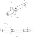
- FIG. 3 shows an extractor 1 for extracting conical spacers 101 according to an embodiment of the invention.
- Said extractor 1 comprises a stem 2 and a handle 4 arranged at one end of the stem 2.
- the stem 2 comprises an engagement area 3A cooperating with the conical spacer 101 for extracting said conical spacer 101.
- the extractor 1 also comprises a mobile element 5 which is displaceable by the user along the stem 2 between a retracted position to which said mobile element 5 is moved in order to contribute to the extraction of the conical spacer 101 from the concrete wall or pillar 201, and an advanced position to which the mobile element 5 is moved in order to push the conical spacer 101 for releasing it from the engagement area 3A of the stem 2.
- the extractor 1 of the invention significantly reduces the time required for extracting conical spacers 101, making the extraction of said conical spacers 101 a simple, effective and quick operation to perform.
- the concrete wall 201 is not damaged with the extractor 1, and therefore the subsequent sealing of the corresponding holes, required in some applications, such as in a retaining wall of a dam, etc., is more effective.
- the conical spacers 101 extracted with the extractor 1 of the invention can be reused because they deteriorate very little during the extraction process, such it contributes to obtain considerable savings in construction material.
- the stem 2 of the preferred embodiment of the invention is cylindrical and internally comprises an at least partially threaded through hole.
- said inner hole is threaded along the entire length thereof, as shown in Figure 5 , although it is also possible for only the ends to be threaded. These threaded means allow easily fixing the handle 4 at one end of the stem 2.
- the extractor 1 comprises a stop 2' arranged at the end of the stem 2 closest to the handle 4, adjacent to same, comprising a stop surface 2A cooperating in the retracted position with a first stop surface 5a comprised in the mobile element 5, as for example shown in Figure 5A .
- Said stop 2' is cylindrical and projects radially from the stem 2.
- the stop 2' is an integral part of the stem 2, as seen in the drawings, but optionally it could be a separate part fixed to the stem 2 by pressure fitting, through threaded means, or by similar processes.
- the stop 2' could comprise at least two protuberances projecting radially from the stem 2, said protuberances being arranged equidistantly around the outer circumference of the stem 2.
- the mobile element 5 of the preferred embodiment of the invention is cylindrical and internally comprises a through hole which is traversed by the stem 2, as shown in Figure 5 , such that the mobile element 5 is allowed to slide along the stem 2.
- the first stop surface 5a of the mobile element 5 is arranged at one end of the mobile element 5, logically at the end arranged closest to the stop 2'.
- said first stop surface 5a is arranged at the bottom of a recess 5e, as shown in the detail of Figure 5A , such that the mobile element 5, being in the retracted position, covers at least part of the stop 2'.
- the extractor 1 comprises another stop 3' arranged at the end of the stem 2 next to the engagement area 3A.
- Said stop 3' comprises a stop surface 3B cooperating in the advanced position with a second stop surface 5b comprised in the mobile element 5, as for example shown in Figure 5B .
- said stop 3' is cylindrical and projects radially from the stem 2, being arranged adjacent to the engagement area 3A.
- the stop 3' and the engagement area 3A form a detachable active end 3 that is fixed to the free end of the stem 2 by non-permanent attachment means, for example threaded means.
- non-permanent attachment means for example threaded means.
- said active end 3 comprises a threaded protuberance 3C at the end opposite the engagement area 3A, as seen in Figure 5B .
- said non-permanent attachment means can comprise a pin.
- the active end 3 To assemble the mobile element 5 on the stem 2, the active end 3 must first be disassembled and once the mobile element 5 is assembled, the active end 3 is fixed to the stem 2 again. The mobile element 5 is thereby trapped between the two stops 2' and 3', the engagement area 3A being arranged outside the area delimited by both stops 2' and 3'. The distance “d" between these two stops 2' and 3' is greater than the length "L" of the mobile element 5, therefore the mobile element 5 can move between these two stops 2' and 3'.
- the active end 3 is not detachable and can be fixed to the end of the stem 2 by other means, such as welding, or it can be configured such that it is an integral part of the stem 2.
- the handle 4 and the stop 2' will be detachable to allow the insertion, and extraction when required, of the mobile element 5, by proceeding in a manner similar to that described in the preceding paragraph.
- the stop 3' could comprise at least two protuberances that project radially from the stem 2, said protuberances being arranged equidistantly around the outer circumference of the stem 2.
- the second stop surface 5b of the mobile element 5 is arranged at the other end of the mobile element 5, i.e., at the end arranged closest to the stop 3'. According to the invention said second stop surface 5b is arranged at the bottom of an internal recess 5c, as for example shown in the detail of Figure 5B , such that the mobile element 5 covers the stop 3' and at least part of the engagement area 3A in the advanced position.
- conical spacers 101 of the state of the art are made of plastic, preferably PVC, and comprise an inner hole to allow the passage of the transverse tie rod. Said inner hole is threaded in some cases and in others it is not.
- both the stem 2 and the mobile element 5 and the active end 3 are metallic, preferably made of steel, and the length "L" of the mobile element 5 is greater than its diameter, as seen in Figure 5 , although other configurations are not ruled out.
- the engagement area 3A of the extractor 1 is conical, as shown in the drawings, which favors the insertion of said engagement area 3A into the inner hole of the corresponding conical spacer 101. Furthermore, said conical configuration enables the engagement area 3A to adapt to different diameters, which favors being able to use the extractor 1 of the invention in different types of conical spacers, it being unnecessary to adapt the conical spacers of the state of the art to use the extractor 1 of the invention.
- the engagement area 3A comprises a threaded area, not depicted in the drawings.
- the threaded area of the engagement area 3A is turned inside the conical spacer 101, the metallic threading generates a small indent inside the corresponding conical spacer 101, both elements being attached to one another.
- the extractor 1 does not have to penetrate far into the conical spacer 101 in order to cause said attachment.
- the user fixes the extractor 1 of the invention to the conical spacer 101 as indicated in the preceding paragraph, i.e., the extractor 1 is turned manually in the inner hole of the conical spacer 101 while the user keeps the extractor 1 upright by the handle 4 in order to make the small indent in the conical spacer 101 if the latter is not previously threaded.
- the user moves the mobile element 5 manually to the retracted position of the extractor 1 such that the mobile element 5 hits against the first stop 2'. Due to the action and reaction forces that are generated, the extractor 1 pulls on the conical spacer 101, extracting it from the concrete wall 201 in a simple, quick and almost effortlessly manner.
- the extraction of the conical spacer 101 is clean, i.e., no cracks are formed in the concrete 201 around the corresponding conical spacer 101, as may occur in the case of using a hammer and chisel.
- the mobile element 5 follows a linear path.
- the mobile element 5 of the extractor 1 is moved manually to the advanced position of the extractor 1, or to a position close to it, where the mobile element 5 pushes the conical spacer 101, quickly and effortlessly releasing it from the engagement area 3A of the extractor 1.
- the mobile element 5 comprises a pushing surface 5d that pushes the corresponding conical spacer 101 out of the engagement area 3A.
- the small indent caused by the engagement area 3A scarcely damages the conical spacer 101, so said conical spacers 101 can be used again, once more contributing to obtaining significant savings in construction material.
- the outer surface of the mobile element 5 is knurled to make handling thereof easier.
Landscapes
- Engineering & Computer Science (AREA)
- Architecture (AREA)
- Mechanical Engineering (AREA)
- Civil Engineering (AREA)
- Structural Engineering (AREA)
- Forms Removed On Construction Sites Or Auxiliary Members Thereof (AREA)
- Piles And Underground Anchors (AREA)
Claims (10)
- Entnahmewerkzeug zur Entnahme von konischen Abstandshaltern (101) in Betonwänden oder -säulen (201), umfassend einen Schaft (2), umfassend an einem seiner Enden einen Eingriffsbereich (3A), der mit dem konischen Abstandshalter (101) zur Entnahme des genannten konischen Abstandshalters (101) zusammenwirkt, einen am anderen Ende des Schafts (2) angeordneten Griff (4) und ein bewegliches Element (5), das vom Benutzer entlang des Schafts (2) zwischen einer eingefahrenen Position, in die das genannte bewegliche Element (5) bewegt wird, um zur Entnahme des konischen Abstandshalters (101) aus der Betonwand oder -säule (201) beizutragen, und einer vorgeschobenen Position verschiebbar ist, wobei der Schaft (2) einen Anschlag (2') umfasst, der an dem Griff (4) nächstgelegenen Ende angeordnet ist und eine Anschlagfläche (2A) umfasst, die in der eingefahrene Position mit einer ersten, in dem beweglichen Element (5) enthaltenen Anschlagfläche (5a) zusammenwirkt, wobei der Schaft (2) einen weiteren Anschlag (3') umfasst, der an dem Eingriffsbereich (3A) nächstgelegenen Ende angeordnet ist, und eine Anschlagfläche (3B) umfasst, die in der Vorschubposition mit einer zweiten, in dem beweglichen Element (5) enthaltenen Anschlagfläche (5b) zusammenwirkt, dadurch gekennzeichnet, dass die genannte zweite Anschlagfläche (5b) unten in einer an einem Ende des beweglichen Elements (5) angeordneten Innenaussparung (5c) angeordnet ist, sodass das bewegliche Element (5), wenn das bewegliche Element (5) in die Vorschubposition bewegt wird, den Eingriffsbereich (3A) zumindest teilweise abdeckt, um den konischen Abstandshalter (101) zum Lösen aus dem Eingriffsbereich des Schafts (2) zu drücken.
- Entnahmewerkzeug nach Anspruch 1, wobei der Eingriffsbereich (3A) angrenzend an den genannten Anschlag (3') so angeordnet ist, dass diese ein aktives Ende (3) bilden, wobei das genannte aktive Ende (3) vorzugsweise abnehmbar ist.
- Entnahmewerkzeug nach Anspruch 2, wobei der Schaft (2) zylindrisch ist und innen ein Loch aufweist, das zumindest teilweise mit einem Gewinde versehen ist, um eine Befestigung am Griff (4) und am aktiven Ende (3) zu ermöglichen.
- Entnahmewerkzeug nach einem der Ansprüche 1 bis 3, wobei die Anschläge (2', 3') des Schafts (2) zylindrisch sind und radial vom Schaft (2) ausragen.
- Entnahmewerkzeug nach einem der Ansprüche 1 bis 4, wobei das bewegliche Element (5) zylindrisch ist und innen ein Durchgangsloch aufweist, das vom Schaft (2) durchquert wird.
- Entnahmewerkzeug nach Anspruch 5, wobei die Länge (L) des beweglichen Elements (5) größer als sein Durchmesser ist.
- Entnahmewerkzeug nach einem der vorstehenden Ansprüche, wobei das bewegliche Element (5) eine weitere Innenaussparung (5e) am gegenüberliegenden Ende aufweist, wobei die erste Anschlagfläche (5a) unten in der genannten Aussparung (5e) angeordnet ist.
- Entnahmewerkzeug nach einem der vorstehenden Ansprüche, wobei der Eingriffsbereich (3A) einen konischen Gewindebereich umfasst.
- Entnahmewerkzeug nach einem der vorstehenden Ansprüche, wobei die Außenfläche des beweglichen Elements (5) gerändelt ist.
- Verfahren zur Entnahme von konischen Abstandshaltern (101) in Betonwänden oder -säulen (201), dadurch gekennzeichnet, dass es Folgendes umfasst: einen Koppelschritt, in dem der Eingriffsbereich (3A) eines Entnahmewerkzeugs (1) nach einem der vorstehenden Ansprüche an dem konischen Abstandshalter (101) fixiert wird, einen Entnahmeschritt, in dem das bewegliche Element (5) des Entnahmewerkzeugs (1) auf einem Linearpfad manuell in die eingefahrene Position des Entnahmewerkzeugs (1) bewegt wird und die Entnahme des entsprechenden konischen Abstandshalters (101) aus der Betonwand oder -säule bewirkt, und einen Ausstoßschritt, in dem das bewegliche Element (5) des Entnahmewerkzeugs (1) manuell in die vorgeschobene Position des Entnahmewerkzeugs (1) oder eine Position in der Nähe desselben bewegt wird, in der das bewegliche Element (5) den konischen Abstandshalter (101) zum Lösen aus dem Eingriffsbereich (3A) des Entnahmewerkzeugs (1) drückt.
Priority Applications (2)
| Application Number | Priority Date | Filing Date | Title |
|---|---|---|---|
| PT15801884T PT3366865T (pt) | 2015-10-20 | 2015-10-20 | Extrator e método para extração de espaçadores cónicos de paredes ou pilares de betão |
| PL15801884T PL3366865T3 (pl) | 2015-10-20 | 2015-10-20 | Wyciągacz i sposób wydobywania stożkowych rozpórek z betonowych ścian lub filarów |
Applications Claiming Priority (1)
| Application Number | Priority Date | Filing Date | Title |
|---|---|---|---|
| PCT/ES2015/070757 WO2017068204A1 (es) | 2015-10-20 | 2015-10-20 | Extractor y método para extraer separadores cónicos en muros o pilares de hormigón |
Publications (2)
| Publication Number | Publication Date |
|---|---|
| EP3366865A1 EP3366865A1 (de) | 2018-08-29 |
| EP3366865B1 true EP3366865B1 (de) | 2019-06-05 |
Family
ID=54707805
Family Applications (1)
| Application Number | Title | Priority Date | Filing Date |
|---|---|---|---|
| EP15801884.6A Active EP3366865B1 (de) | 2015-10-20 | 2015-10-20 | Entnahmewerkzeug und methode zur entnahme von konischen abstandshaltern aus betonwänden oder säulen |
Country Status (11)
| Country | Link |
|---|---|
| US (1) | US10934726B2 (de) |
| EP (1) | EP3366865B1 (de) |
| CN (1) | CN108138504B (de) |
| CA (1) | CA3002721C (de) |
| DK (1) | DK3366865T3 (de) |
| ES (1) | ES2744535T3 (de) |
| IL (1) | IL258407B (de) |
| MX (1) | MX366861B (de) |
| PL (1) | PL3366865T3 (de) |
| PT (1) | PT3366865T (de) |
| WO (1) | WO2017068204A1 (de) |
Families Citing this family (3)
| Publication number | Priority date | Publication date | Assignee | Title |
|---|---|---|---|---|
| EP3366865B1 (de) * | 2015-10-20 | 2019-06-05 | 20Emma20 S.L. | Entnahmewerkzeug und methode zur entnahme von konischen abstandshaltern aus betonwänden oder säulen |
| KR102568018B1 (ko) * | 2021-11-29 | 2023-08-18 | 임태형 | 거푸집 세퍼레이터용 고정 및 회수 망치 |
| US12318901B2 (en) * | 2021-12-07 | 2025-06-03 | Melvin Douglas Law | Nail pulling or removing device for use with a palm nailer |
Family Cites Families (20)
| Publication number | Priority date | Publication date | Assignee | Title |
|---|---|---|---|---|
| US3750500A (en) * | 1971-04-29 | 1973-08-07 | A Peterson | Dowel pin extractor tool |
| US3835489A (en) * | 1973-07-25 | 1974-09-17 | N Sherman | Universal cone extractor |
| US4109893A (en) | 1975-07-22 | 1978-08-29 | Laroche Jean Pierre | Form panel spacing device |
| FR2333917A1 (fr) * | 1975-12-04 | 1977-07-01 | Laroche Jean Pierre | Dispositif pour assurer l'ecartement des banches lors du coffrage de parois en beton et outil pour extraire ce dispositif |
| DE2944710A1 (de) * | 1979-11-06 | 1981-05-07 | Christos Dr. Dimakos | Vorrichtung zum entfernen einer knochenzementroehre bei einer reimplantation eines kuenstlichen oberschenkelhalskopfes |
| USD272712S (en) * | 1981-12-30 | 1984-02-21 | Allen Steven R | Combined slide hammer nail puller and building wrecking tool |
| US5813185A (en) | 1996-04-29 | 1998-09-29 | Jackson; George W. | Spacer reciever for a wall form tie rod |
| JP2000345705A (ja) | 1999-06-08 | 2000-12-12 | Yoshitaka Hirukotani | コンクリート壁突出ボルト除去装置 |
| WO2006107401A2 (en) * | 2005-02-09 | 2006-10-12 | Arthrocare Corporation | Lockable slide hammer and gripping apparatus |
| CN201133080Y (zh) * | 2007-12-05 | 2008-10-15 | 中国水利水电第五工程局 | 可方便拆卸的对拉螺栓配套装置 |
| US8166624B2 (en) * | 2008-01-17 | 2012-05-01 | Jon Andreasen | Linearly extendible impact anchor driving pole and anchor system |
| CN201474301U (zh) * | 2009-08-28 | 2010-05-19 | 新疆建工(集团)有限责任公司 | 模板拉筋组件 |
| JP2012046973A (ja) | 2010-08-27 | 2012-03-08 | Shuwa Co Ltd | コンクリート型枠の間隔保持具 |
| US8407874B2 (en) * | 2010-09-24 | 2013-04-02 | Las Vegas Tool Llc | Pulling pliers method and apparatus |
| JP3182061U (ja) | 2012-12-21 | 2013-03-07 | 幸三郎 高木 | 型枠保持用コーン、およびその型枠保持用コーンを取外すために使用するスクリュードライバー |
| JP3184037U (ja) | 2013-01-17 | 2013-06-13 | 株式会社京都スペーサー | 型枠受具引き抜きレンチ |
| CN203471673U (zh) * | 2013-08-07 | 2014-03-12 | 杭州诺邦无纺股份有限公司 | 一种传动轴内置轴承拆卸工具 |
| JP5748167B1 (ja) | 2015-02-21 | 2015-07-15 | Rtb株式会社 | 型枠間隔保持用コーン |
| CN104723255A (zh) * | 2015-04-02 | 2015-06-24 | 中航飞机股份有限公司西安飞机分公司 | 一种螺栓拔出器及其使用方法 |
| EP3366865B1 (de) * | 2015-10-20 | 2019-06-05 | 20Emma20 S.L. | Entnahmewerkzeug und methode zur entnahme von konischen abstandshaltern aus betonwänden oder säulen |
-
2015
- 2015-10-20 EP EP15801884.6A patent/EP3366865B1/de active Active
- 2015-10-20 PT PT15801884T patent/PT3366865T/pt unknown
- 2015-10-20 CN CN201580083934.9A patent/CN108138504B/zh active Active
- 2015-10-20 CA CA3002721A patent/CA3002721C/en active Active
- 2015-10-20 DK DK15801884.6T patent/DK3366865T3/da active
- 2015-10-20 ES ES15801884T patent/ES2744535T3/es active Active
- 2015-10-20 PL PL15801884T patent/PL3366865T3/pl unknown
- 2015-10-20 WO PCT/ES2015/070757 patent/WO2017068204A1/es not_active Ceased
- 2015-10-20 MX MX2018004500A patent/MX366861B/es active IP Right Grant
-
2018
- 2018-03-27 IL IL25840718A patent/IL258407B/en active IP Right Grant
- 2018-04-13 US US15/952,763 patent/US10934726B2/en active Active
Non-Patent Citations (1)
| Title |
|---|
| None * |
Also Published As
| Publication number | Publication date |
|---|---|
| CA3002721A1 (en) | 2017-04-27 |
| ES2744535T3 (es) | 2020-02-25 |
| US10934726B2 (en) | 2021-03-02 |
| CN108138504A (zh) | 2018-06-08 |
| DK3366865T3 (da) | 2019-09-02 |
| MX2018004500A (es) | 2018-08-01 |
| US20180230702A1 (en) | 2018-08-16 |
| CN108138504B (zh) | 2020-06-02 |
| PT3366865T (pt) | 2019-09-17 |
| CA3002721C (en) | 2023-02-14 |
| IL258407B (en) | 2019-11-28 |
| WO2017068204A1 (es) | 2017-04-27 |
| PL3366865T3 (pl) | 2019-11-29 |
| EP3366865A1 (de) | 2018-08-29 |
| IL258407A (en) | 2018-05-31 |
| MX366861B (es) | 2019-07-25 |
Similar Documents
| Publication | Publication Date | Title |
|---|---|---|
| EP3146122B1 (de) | Kappe für die verankerung eines verankerungssystems nach spannung | |
| CA2970893C (en) | Sealing plug for closing holes in walls and the like | |
| EP3366865B1 (de) | Entnahmewerkzeug und methode zur entnahme von konischen abstandshaltern aus betonwänden oder säulen | |
| KR100907088B1 (ko) | 거푸집 지지 웨일러 | |
| CA2984051C (en) | Formwork tube | |
| EP2886745B1 (de) | Abstandsspannungselement zur Bereitstellung von Schalungen für wasserdichte Betonwände | |
| US2002526A (en) | Concrete form holding means | |
| DE19951359C1 (de) | Verschließbarer Distanzhalter für Betonschalungswände | |
| CN204370699U (zh) | 用于封堵钢筋连接套筒的开口的钢筋连接套筒防护头 | |
| CN203821869U (zh) | 建筑施工洞口安全防护装置 | |
| EP3556944B1 (de) | Schachtabdeckungsrahmen, schachtabdeckungsanordnung, schachtanordnung und installationsverfahren | |
| JP6166522B2 (ja) | ねじ節鉄筋回転用治具 | |
| EP1550781A2 (de) | Endstück für ein Distanzrohr zum Führen von Spannstäben | |
| EP1835091A2 (de) | Distanzrohr für Spannstäbe | |
| CN206768568U (zh) | 一种可重复利用的快速安拆附壁式栈桥 | |
| NL7908737A (nl) | Afstandhoudersamenstel. | |
| EP3631269B1 (de) | Kupplung zur herstellung einer pressverbindung zwischen zwei rohren | |
| CN120401651A (zh) | 预制梁或者预制柱的手孔连接装置、制备方法与连接方法 | |
| EP2594837A1 (de) | Verschlusselement für Rohre |
Legal Events
| Date | Code | Title | Description |
|---|---|---|---|
| STAA | Information on the status of an ep patent application or granted ep patent |
Free format text: STATUS: THE INTERNATIONAL PUBLICATION HAS BEEN MADE |
|
| PUAI | Public reference made under article 153(3) epc to a published international application that has entered the european phase |
Free format text: ORIGINAL CODE: 0009012 |
|
| STAA | Information on the status of an ep patent application or granted ep patent |
Free format text: STATUS: REQUEST FOR EXAMINATION WAS MADE |
|
| 17P | Request for examination filed |
Effective date: 20180522 |
|
| AK | Designated contracting states |
Kind code of ref document: A1 Designated state(s): AL AT BE BG CH CY CZ DE DK EE ES FI FR GB GR HR HU IE IS IT LI LT LU LV MC MK MT NL NO PL PT RO RS SE SI SK SM TR |
|
| AX | Request for extension of the european patent |
Extension state: BA ME |
|
| DAV | Request for validation of the european patent (deleted) | ||
| DAX | Request for extension of the european patent (deleted) | ||
| GRAP | Despatch of communication of intention to grant a patent |
Free format text: ORIGINAL CODE: EPIDOSNIGR1 |
|
| STAA | Information on the status of an ep patent application or granted ep patent |
Free format text: STATUS: GRANT OF PATENT IS INTENDED |
|
| INTG | Intention to grant announced |
Effective date: 20190327 |
|
| GRAS | Grant fee paid |
Free format text: ORIGINAL CODE: EPIDOSNIGR3 |
|
| GRAA | (expected) grant |
Free format text: ORIGINAL CODE: 0009210 |
|
| STAA | Information on the status of an ep patent application or granted ep patent |
Free format text: STATUS: THE PATENT HAS BEEN GRANTED |
|
| AK | Designated contracting states |
Kind code of ref document: B1 Designated state(s): AL AT BE BG CH CY CZ DE DK EE ES FI FR GB GR HR HU IE IS IT LI LT LU LV MC MK MT NL NO PL PT RO RS SE SI SK SM TR |
|
| REG | Reference to a national code |
Ref country code: GB Ref legal event code: FG4D |
|
| REG | Reference to a national code |
Ref country code: CH Ref legal event code: EP |
|
| REG | Reference to a national code |
Ref country code: AT Ref legal event code: REF Ref document number: 1140118 Country of ref document: AT Kind code of ref document: T Effective date: 20190615 |
|
| REG | Reference to a national code |
Ref country code: IE Ref legal event code: FG4D |
|
| REG | Reference to a national code |
Ref country code: DE Ref legal event code: R096 Ref document number: 602015031501 Country of ref document: DE |
|
| REG | Reference to a national code |
Ref country code: NL Ref legal event code: FP |
|
| REG | Reference to a national code |
Ref country code: CH Ref legal event code: NV Representative=s name: DENNEMEYER AG, CH |
|
| REG | Reference to a national code |
Ref country code: DK Ref legal event code: T3 Effective date: 20190827 |
|
| REG | Reference to a national code |
Ref country code: NO Ref legal event code: T2 Effective date: 20190605 |
|
| REG | Reference to a national code |
Ref country code: SE Ref legal event code: TRGR |
|
| REG | Reference to a national code |
Ref country code: PT Ref legal event code: SC4A Ref document number: 3366865 Country of ref document: PT Date of ref document: 20190917 Kind code of ref document: T Free format text: AVAILABILITY OF NATIONAL TRANSLATION Effective date: 20190828 |
|
| REG | Reference to a national code |
Ref country code: LT Ref legal event code: MG4D |
|
| PG25 | Lapsed in a contracting state [announced via postgrant information from national office to epo] |
Ref country code: LT Free format text: LAPSE BECAUSE OF FAILURE TO SUBMIT A TRANSLATION OF THE DESCRIPTION OR TO PAY THE FEE WITHIN THE PRESCRIBED TIME-LIMIT Effective date: 20190605 Ref country code: HR Free format text: LAPSE BECAUSE OF FAILURE TO SUBMIT A TRANSLATION OF THE DESCRIPTION OR TO PAY THE FEE WITHIN THE PRESCRIBED TIME-LIMIT Effective date: 20190605 Ref country code: FI Free format text: LAPSE BECAUSE OF FAILURE TO SUBMIT A TRANSLATION OF THE DESCRIPTION OR TO PAY THE FEE WITHIN THE PRESCRIBED TIME-LIMIT Effective date: 20190605 Ref country code: AL Free format text: LAPSE BECAUSE OF FAILURE TO SUBMIT A TRANSLATION OF THE DESCRIPTION OR TO PAY THE FEE WITHIN THE PRESCRIBED TIME-LIMIT Effective date: 20190605 |
|
| PG25 | Lapsed in a contracting state [announced via postgrant information from national office to epo] |
Ref country code: BG Free format text: LAPSE BECAUSE OF FAILURE TO SUBMIT A TRANSLATION OF THE DESCRIPTION OR TO PAY THE FEE WITHIN THE PRESCRIBED TIME-LIMIT Effective date: 20190905 Ref country code: RS Free format text: LAPSE BECAUSE OF FAILURE TO SUBMIT A TRANSLATION OF THE DESCRIPTION OR TO PAY THE FEE WITHIN THE PRESCRIBED TIME-LIMIT Effective date: 20190605 Ref country code: GR Free format text: LAPSE BECAUSE OF FAILURE TO SUBMIT A TRANSLATION OF THE DESCRIPTION OR TO PAY THE FEE WITHIN THE PRESCRIBED TIME-LIMIT Effective date: 20190906 Ref country code: LV Free format text: LAPSE BECAUSE OF FAILURE TO SUBMIT A TRANSLATION OF THE DESCRIPTION OR TO PAY THE FEE WITHIN THE PRESCRIBED TIME-LIMIT Effective date: 20190605 |
|
| PG25 | Lapsed in a contracting state [announced via postgrant information from national office to epo] |
Ref country code: RO Free format text: LAPSE BECAUSE OF FAILURE TO SUBMIT A TRANSLATION OF THE DESCRIPTION OR TO PAY THE FEE WITHIN THE PRESCRIBED TIME-LIMIT Effective date: 20190605 Ref country code: EE Free format text: LAPSE BECAUSE OF FAILURE TO SUBMIT A TRANSLATION OF THE DESCRIPTION OR TO PAY THE FEE WITHIN THE PRESCRIBED TIME-LIMIT Effective date: 20190605 Ref country code: SK Free format text: LAPSE BECAUSE OF FAILURE TO SUBMIT A TRANSLATION OF THE DESCRIPTION OR TO PAY THE FEE WITHIN THE PRESCRIBED TIME-LIMIT Effective date: 20190605 |
|
| REG | Reference to a national code |
Ref country code: ES Ref legal event code: FG2A Ref document number: 2744535 Country of ref document: ES Kind code of ref document: T3 Effective date: 20200225 |
|
| PG25 | Lapsed in a contracting state [announced via postgrant information from national office to epo] |
Ref country code: SM Free format text: LAPSE BECAUSE OF FAILURE TO SUBMIT A TRANSLATION OF THE DESCRIPTION OR TO PAY THE FEE WITHIN THE PRESCRIBED TIME-LIMIT Effective date: 20190605 Ref country code: IS Free format text: LAPSE BECAUSE OF FAILURE TO SUBMIT A TRANSLATION OF THE DESCRIPTION OR TO PAY THE FEE WITHIN THE PRESCRIBED TIME-LIMIT Effective date: 20191005 |
|
| REG | Reference to a national code |
Ref country code: DE Ref legal event code: R097 Ref document number: 602015031501 Country of ref document: DE |
|
| PG25 | Lapsed in a contracting state [announced via postgrant information from national office to epo] |
Ref country code: TR Free format text: LAPSE BECAUSE OF FAILURE TO SUBMIT A TRANSLATION OF THE DESCRIPTION OR TO PAY THE FEE WITHIN THE PRESCRIBED TIME-LIMIT Effective date: 20190605 |
|
| PLBE | No opposition filed within time limit |
Free format text: ORIGINAL CODE: 0009261 |
|
| STAA | Information on the status of an ep patent application or granted ep patent |
Free format text: STATUS: NO OPPOSITION FILED WITHIN TIME LIMIT |
|
| 26N | No opposition filed |
Effective date: 20200306 |
|
| PG25 | Lapsed in a contracting state [announced via postgrant information from national office to epo] |
Ref country code: MC Free format text: LAPSE BECAUSE OF FAILURE TO SUBMIT A TRANSLATION OF THE DESCRIPTION OR TO PAY THE FEE WITHIN THE PRESCRIBED TIME-LIMIT Effective date: 20190605 |
|
| PG25 | Lapsed in a contracting state [announced via postgrant information from national office to epo] |
Ref country code: LU Free format text: LAPSE BECAUSE OF NON-PAYMENT OF DUE FEES Effective date: 20191020 |
|
| PG25 | Lapsed in a contracting state [announced via postgrant information from national office to epo] |
Ref country code: CY Free format text: LAPSE BECAUSE OF FAILURE TO SUBMIT A TRANSLATION OF THE DESCRIPTION OR TO PAY THE FEE WITHIN THE PRESCRIBED TIME-LIMIT Effective date: 20190605 |
|
| PG25 | Lapsed in a contracting state [announced via postgrant information from national office to epo] |
Ref country code: MT Free format text: LAPSE BECAUSE OF FAILURE TO SUBMIT A TRANSLATION OF THE DESCRIPTION OR TO PAY THE FEE WITHIN THE PRESCRIBED TIME-LIMIT Effective date: 20190605 Ref country code: HU Free format text: LAPSE BECAUSE OF FAILURE TO SUBMIT A TRANSLATION OF THE DESCRIPTION OR TO PAY THE FEE WITHIN THE PRESCRIBED TIME-LIMIT; INVALID AB INITIO Effective date: 20151020 |
|
| PG25 | Lapsed in a contracting state [announced via postgrant information from national office to epo] |
Ref country code: SI Free format text: LAPSE BECAUSE OF FAILURE TO SUBMIT A TRANSLATION OF THE DESCRIPTION OR TO PAY THE FEE WITHIN THE PRESCRIBED TIME-LIMIT Effective date: 20190605 |
|
| REG | Reference to a national code |
Ref country code: AT Ref legal event code: UEP Ref document number: 1140118 Country of ref document: AT Kind code of ref document: T Effective date: 20190605 |
|
| PG25 | Lapsed in a contracting state [announced via postgrant information from national office to epo] |
Ref country code: MK Free format text: LAPSE BECAUSE OF FAILURE TO SUBMIT A TRANSLATION OF THE DESCRIPTION OR TO PAY THE FEE WITHIN THE PRESCRIBED TIME-LIMIT Effective date: 20190605 |
|
| P01 | Opt-out of the competence of the unified patent court (upc) registered |
Effective date: 20230404 |
|
| REG | Reference to a national code |
Ref country code: CH Ref legal event code: U11 Free format text: ST27 STATUS EVENT CODE: U-0-0-U10-U11 (AS PROVIDED BY THE NATIONAL OFFICE) Effective date: 20251101 |
|
| PGFP | Annual fee paid to national office [announced via postgrant information from national office to epo] |
Ref country code: NL Payment date: 20251026 Year of fee payment: 11 |
|
| PGFP | Annual fee paid to national office [announced via postgrant information from national office to epo] |
Ref country code: PT Payment date: 20251002 Year of fee payment: 11 |
|
| PGFP | Annual fee paid to national office [announced via postgrant information from national office to epo] |
Ref country code: DE Payment date: 20251029 Year of fee payment: 11 |
|
| PGFP | Annual fee paid to national office [announced via postgrant information from national office to epo] |
Ref country code: GB Payment date: 20251027 Year of fee payment: 11 |
|
| PGFP | Annual fee paid to national office [announced via postgrant information from national office to epo] |
Ref country code: NO Payment date: 20251029 Year of fee payment: 11 |
|
| PGFP | Annual fee paid to national office [announced via postgrant information from national office to epo] |
Ref country code: AT Payment date: 20251029 Year of fee payment: 11 |
|
| PGFP | Annual fee paid to national office [announced via postgrant information from national office to epo] |
Ref country code: IT Payment date: 20251021 Year of fee payment: 11 Ref country code: DK Payment date: 20251027 Year of fee payment: 11 |
|
| PGFP | Annual fee paid to national office [announced via postgrant information from national office to epo] |
Ref country code: FR Payment date: 20251027 Year of fee payment: 11 |
|
| PGFP | Annual fee paid to national office [announced via postgrant information from national office to epo] |
Ref country code: BE Payment date: 20251027 Year of fee payment: 11 |
|
| PGFP | Annual fee paid to national office [announced via postgrant information from national office to epo] |
Ref country code: SE Payment date: 20251027 Year of fee payment: 11 Ref country code: CH Payment date: 20251101 Year of fee payment: 11 |
|
| PGFP | Annual fee paid to national office [announced via postgrant information from national office to epo] |
Ref country code: IE Payment date: 20251027 Year of fee payment: 11 Ref country code: CZ Payment date: 20251007 Year of fee payment: 11 |
|
| PGFP | Annual fee paid to national office [announced via postgrant information from national office to epo] |
Ref country code: PL Payment date: 20251003 Year of fee payment: 11 |
|
| PGFP | Annual fee paid to national office [announced via postgrant information from national office to epo] |
Ref country code: ES Payment date: 20251107 Year of fee payment: 11 |