EP3556944B1 - Schachtabdeckungsrahmen, schachtabdeckungsanordnung, schachtanordnung und installationsverfahren - Google Patents
Schachtabdeckungsrahmen, schachtabdeckungsanordnung, schachtanordnung und installationsverfahren Download PDFInfo
- Publication number
- EP3556944B1 EP3556944B1 EP19164383.2A EP19164383A EP3556944B1 EP 3556944 B1 EP3556944 B1 EP 3556944B1 EP 19164383 A EP19164383 A EP 19164383A EP 3556944 B1 EP3556944 B1 EP 3556944B1
- Authority
- EP
- European Patent Office
- Prior art keywords
- frame
- shaft
- predetermined breaking
- apron
- breaking point
- Prior art date
- Legal status (The legal status is an assumption and is not a legal conclusion. Google has not performed a legal analysis and makes no representation as to the accuracy of the status listed.)
- Active
Links
Images


Classifications
-
- E—FIXED CONSTRUCTIONS
- E02—HYDRAULIC ENGINEERING; FOUNDATIONS; SOIL SHIFTING
- E02D—FOUNDATIONS; EXCAVATIONS; EMBANKMENTS; UNDERGROUND OR UNDERWATER STRUCTURES
- E02D29/00—Independent underground or underwater structures; Retaining walls
- E02D29/12—Manhole shafts; Other inspection or access chambers; Accessories therefor
- E02D29/121—Manhole shafts; Other inspection or access chambers; Accessories therefor characterised by the connection between shaft elements, e.g. of rings forming said shaft
Definitions
- the invention relates to a manhole cover frame according to the preamble of claim 1, a manhole cover arrangement herewith according to claim 10, a manhole arrangement with such a manhole cover arrangement according to claim 11 and a method for installing the manhole cover frame according to claim 12.
- Manhole cover arrangements are used to cover manholes and usually have a manhole cover frame and a closure element with which a passage opening in the manhole cover frame can be closed.
- Such manhole cover frames are installed in particular at the upper end of a manhole structure.
- a floor-level installation of the manhole cover frame and the closure element in the traffic area is necessary.
- the problem with the current state of the art is that the distance between the shaft structure and the traffic area is variable. If the building contractor knows about this in advance, distance, he can order a manhole cover arrangement that is a suitable length. Even with advance planning, but especially during renovations, it often turns out on the construction site that the height of the manhole cover arrangement brought with it is too great and would protrude beyond the traffic area if installed. In practice, construction work is then interrupted until a shorter manhole cover arrangement arrives. This results in additional costs due to repeated trips, ordering processes and securing the construction site. In addition, traffic on the traffic area is impeded for a longer period of time.
- a manhole cover frame for a manhole cover arrangement for use in new road construction and in rehabilitation processes. This has a frame apron through which a manhole passage runs. The manhole cover frame also has a locking element holder.
- EP 2 317 197 A1 indicates a dimensionally stable water pipe that has a sleeve with a metal layer and a plastic layer. This sleeve has predetermined breaking points for cutting to length.
- EN 10 2006 056 146 A1 specifies an installation body for floor slabs of buildings, which forms a service opening to a pipeline under the floor slab, as described by way of example to a backflow flap.
- This installation body has a vertically aligned passage into which an elongated, rectangular attachment element with a connection piece is inserted.
- This attachment element is cast into the floor slab with the connection piece (together with the installation body) in such a way that its upper side is flush with the surface of the floor slab.
- the insertion section Due to different thicknesses of the floor slabs and distances of the pipeline lying under the floor line, the insertion section is designed to be shortened.
- the connection piece has cutting markings at which the piece can be cut according to EN 10 2006 056 146 A1 can be sawn off.
- the connection piece according to EN 10 2006 056 146 A1 there is a single cutting mark designed as a predetermined breaking point.
- the object of the invention is to provide a manhole cover arrangement, individual parts thereof or method instructions with which the aforementioned disadvantages are overcome so that the installation of the manhole cover arrangement can be continued without having to interrupt the construction site activity.
- the invention relates to a manhole cover frame for a manhole cover arrangement for use in new road construction and in renovation processes, which forms a manhole passage running in a longitudinal direction, with a closure element receptacle, in particular for receiving a closure element of a manhole cover arrangement with which the manhole passage can be closed, and with a frame apron with an inner side, an outer side and a length in the longitudinal direction, wherein the manhole passage runs through the frame apron, wherein the frame apron has a first predetermined breaking point that runs transversely to the longitudinal direction, and the frame apron is divided into a first section that borders the closure element receptacle and a second section that can be broken off specifically along the first predetermined breaking point, namely in such a way that the length of the frame apron can be shortened, in particular irreversibly by breaking or breaking off, wherein the first predetermined breaking point runs along the circumference of the frame apron.
- the manhole cover frame is made of cast iron and the first predetermined breaking point is designed as a predetermined breaking groove at least in sections, wherein the frame apron has a wall thickness and the predetermined breaking groove has a groove depth which is at least 25% of the wall thickness of the frame apron in the region of the predetermined breaking groove.
- the building contractor now has the option of using this manhole cover frame according to the invention to adjust the length of the manhole cover frame by shortening the frame apron in order to adapt it to the existing road structure without having to leave the construction site. Due to the predetermined breaking point, this can be achieved in particular with inexpensive and almost always available tools, e.g. a hammer, a spade or a pickaxe. The breaking off is also much faster, more precise and less dangerous than, for example, cutting off with a grinder.
- the targeted breaking off leads to an irreversible division of the entire component and is based on a targeted mechanical Initiation of crack formation in the area of the predetermined breaking point, whereby the first section of the manhole cover frame alone remains usable, in particular because this first section is not damaged.
- the first predetermined breaking point runs along the circumference of the frame apron, an even shortening of the frame apron over the circumference can be achieved.
- the first predetermined breaking point is designed as a predetermined breaking groove at least in sections, with the predetermined breaking groove preferably running along the entire circumference of the frame apron.
- a predetermined breaking groove contributes to a clean break-off edge and is easy to produce. This also prevents damage to the first section in particular. If it runs over the entire circumference, the break-off edge is also cleanly defined over the entire circumference.
- the predetermined breaking groove is arranged on the outside of the frame apron. On the one hand, this contributes to a smooth surface on the inside of the frame apron. On the other hand, a blow with a tool to trigger a predetermined breaking point on the outside can be carried out easily and precisely.
- the frame apron has a wall thickness and the predetermined breaking groove has a groove depth that is at least 25%, and preferably at least 30%, of the wall thickness of the frame apron in the area of the predetermined breaking groove.
- the frame apron is thus weakened in this area compared to the adjacent wall thickness of the frame apron to such an extent that the predetermined breaking point can be produced cleanly along the predetermined breaking groove.
- the groove depth is a maximum of 60%, and preferably a maximum of 50%, of the wall thickness of the frame apron in the area of the predetermined breaking groove.
- the second section is thus still comparatively stable connected to the first section of the frame apron and can bear traffic loads even when not shortened.
- the predetermined breaking groove has a rounded groove cross-section. Due to the lack of corners in the cross-sectional profile, larger traffic loads can be transferred between the first and second sections without spontaneous material fractures occurring at the predetermined breaking point. In addition, a minimum wall thickness is achieved in the area of the groove base along a tangent line along which the predetermined breaking point can be achieved.
- the frame apron has at least one second predetermined breaking point, which runs transversely to the longitudinal direction and divides the breakable second section of the frame apron into a a first section that can be broken off in a targeted manner and a further section that can be broken off in a targeted manner, in particular in such a way that the length of the frame apron can be shortened to two different values, in particular irreversibly by breaking or breaking off.
- the at least one second predetermined breaking point should be arranged between the first predetermined breaking point and an end of the frame apron facing away from the closure element holder.
- the second predetermined breaking point In a design with at least one such second predetermined breaking point, it is advantageous to dimension the second predetermined breaking point so that it is weaker than the first predetermined breaking point. This allows the predetermined breaking point to be achieved at the second predetermined breaking point with a low risk of triggering a predetermined breaking point at the first predetermined breaking point.
- the second predetermined breaking point can optionally have the individual optional features of the first predetermined breaking point.
- the second predetermined breaking point can optionally run along the circumference of the frame apron.
- the second predetermined breaking point can also be designed as a predetermined breaking groove, at least in sections. It is advantageous if the predetermined breaking groove of the second predetermined breaking point is arranged on the outside of the frame apron.
- the frame apron has a wall thickness and the predetermined breaking groove of the second predetermined breaking point has a groove depth that is at least 25%, and preferably at least 30%, of the wall thickness of the frame apron in the area of the predetermined breaking groove.
- the groove depth of the predetermined breaking groove of the second predetermined breaking point is a maximum of 60%, and preferably a maximum of 50%, of the wall thickness of the frame apron in the area of the predetermined breaking groove.
- the predetermined breaking groove of the second predetermined breaking point has a rounded groove cross-section.
- the breakable second section of the frame apron has at least one segmentation predetermined breaking point that runs in the longitudinal direction and divides the second section or at least one of its subsections in the circumferential direction of the frame apron, in particular such that the second section can be broken off as an open ring or in circumferential segments, in particular irreversibly by breaking or breaking off. If only a single segmentation predetermined breaking point is provided, this serves as the beginning of the predetermined breaking point. Depending on how brittle the ring apron is, the entire open ring then comes loose or segments are broken off piece by piece.
- the at least one segmentation predetermined breaking point extends between the first predetermined breaking point and an end of the frame skirt facing away from the closure element holder.
- the at least one segmentation predetermined breaking point can either extend over the entire length of the second section in the longitudinal direction or extend over the entire length of a partial section of the second section in the longitudinal direction. As a result, the adjacent parts of the second section do not remain attached to one another when knocked off.
- Breaking or breaking is particularly easy if at least two segmentation break points are distributed over the circumference of the second section, preferably evenly distributed. This means that the segments can be easily broken off or broken off individually. Furthermore, the entire second section can be separated from the first section particularly quickly if the segmentation break points are aligned across the boundaries of the sections when the second section is divided into at least two sections.
- the segmentation breaking points run in a common plane with the longitudinal direction. This means that the longitudinally aligned breaking edges are short when breaking off.
- the segmentation predetermined breaking points can optionally have the individual optional features of the first predetermined breaking point.
- the segmentation predetermined breaking points can each be designed as a predetermined breaking groove, at least in sections. It is advantageous if the predetermined breaking groove of the segmentation predetermined breaking points is arranged on the outside of the frame apron. With regard to the dimensioning, it is preferable that the frame apron has a wall thickness and the predetermined breaking groove of the segmentation predetermined breaking points each have a groove depth that is at least 25%, and preferably at least 30%, of the wall thickness of the frame apron in the area of the predetermined breaking groove.
- the groove depth of the predetermined breaking groove of the segmentation predetermined breaking points is a maximum of 60%, and preferably a maximum of 50%, of the wall thickness of the frame apron in the area of the predetermined breaking groove.
- the predetermined breaking groove of the segmentation predetermined breaking points each have a rounded groove cross-section.
- the segmentation breaking points are stronger than the first and/or second breaking points.
- the groove depth of the Segmentation breaking points should be less deep than the adjacent breaking grooves of the first and/or second breaking point. This means that a crack caused by breaking or fracture separation will preferably continue along the first and/or second breaking point. This creates a straight breaking edge.
- the closure element holder is formed in one piece with the frame apron. This is inexpensive to manufacture and a high level of stability is achieved.
- the manhole cover frame as such is preferably formed in one piece. This can also include a frame collar. This can protrude radially beyond the frame apron. It can also form a traffic area.
- a variant in which the frame apron or the manhole cover frame is made of cast iron is particularly stable and at the same time brittle enough to produce a predetermined breaking point.
- the invention further relates to a manhole cover arrangement for use in new road construction and in renovation processes, with a manhole cover frame as described above and below and a closure element, wherein the manhole passage can be closed by positioning the closure element on the closure element holder.
- a manhole cover frame as described above and below and a closure element, wherein the manhole passage can be closed by positioning the closure element on the closure element holder.
- the invention also relates to a shaft arrangement with a shaft cover arrangement as described above and below and a shaft structure, wherein the shaft cover frame with the frame apron extends into the shaft structure.
- This shaft arrangement it is possible to adapt the length of the shaft cover frame or its frame apron to the relative position of the shaft structure to the traffic area.
- the frame apron can be inserted into a centering ring of the shaft structure.
- the centering ring preferably forms a guide for the frame apron.
- the frame apron is preferably mounted in the centering ring so that it can be moved longitudinally. This allows the shaft cover frame to be rolled into the road surface and levels itself in the process.
- Such centering rings are used in particular when the frame apron has a larger outer diameter than the inner diameter of the shaft structure at its upper end. With such diameter ratios, a collision between the shaft structure and the frame apron can be prevented by breaking off the second section.
- breaking off the second section is also useful in designs where the The outer diameter of the frame apron is approximately as large as the inner diameter of the shaft structure. If the frame apron is immersed deeply in the shaft structure, it can become jammed, particularly in traffic areas that are at an angle to the shaft structure, which in the worst case can lead to damage to the shaft structure. This can be avoided by shortening the frame apron.
- the shaft structure can in particular form a circular opening for the frame apron. Accordingly, the frame apron should also have a substantially cylindrical outer surface. Furthermore, the shaft structure according to the invention preferably consists essentially of concrete. However, the optional centering ring can consist of concrete or of metal, e.g. cast iron.
- the invention also relates to a method for installing a manhole cover frame, as described above and below, on a manhole structure, which comprises the following steps. First, an available installation height for the manhole cover frame between an upper end of the manhole structure and the desired installation height of the closure element holder is determined. The manhole cover frame is then installed either without shortening the frame apron if the available installation height is greater than a defined limit value, or only after shortening the frame apron in the longitudinal direction by at least partially breaking off the second section at a predetermined breaking point if the available installation height is less than the defined limit value. This allows the length of the manhole cover arrangement to be adjusted quickly and inexpensively on site.
- the break-off is carried out by hitting the second section with an impact tool, especially a hammer (e.g. a sledgehammer).
- an impact tool especially a hammer (e.g. a sledgehammer).
- a hammer e.g. a sledgehammer
- Construction workers are also very familiar with how to use hammers and a hammer is almost always carried with them.
- a hammer can be obtained quickly.
- the predetermined breaking points should therefore be designed for breaking off with an impact tool.
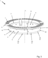
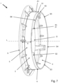
- the Fig. 1 to 3 each show in a perspective view a manhole cover frame 1 for a manhole cover arrangement (80, cf. Fig. 17 ) for use in new road construction and in renovation processes.
- This forms a manhole passage D running in a longitudinal direction L.
- the manhole cover frame 1 On the upper side, the manhole cover frame 1 has a closure element holder 2 for holding a closure element (81, cf. Fig. 17 ) of a manhole cover arrangement (80, cf. Fig. 17 ) with which the shaft passage D can be closed.
- the closure element holder 2 is radially enclosed by a frame collar 6, which forms an upper traffic area 7.
- a tubular frame apron 3 with an inner side 4, an outer side 5 and a length X in the longitudinal direction L is connected to the closure element holder 2 in the longitudinal direction L.
- the frame collar 6 projects radially beyond the frame apron 3.
- the shaft passage D runs through this frame apron 3 as well as the closure element holder 2 and the frame collar 6.
- the manhole cover frame 1 is made of cast iron in one piece, in particular including the locking element holder 2, the frame collar 6 and the frame apron 3.
- the frame apron 3 has a first predetermined breaking point 10 which runs transversely to the longitudinal direction L, and the frame apron 3 is divided into a first section A1 which borders on the closure element holder 2, and a breakable second section A2.
- the first predetermined breaking point 10 is designed as a predetermined breaking groove 11 on the outside 5 of the frame apron 3, which runs along the entire circumference of the frame apron 3.
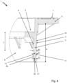
- the frame apron 3 has a wall thickness W and the predetermined breaking groove 11 has a groove depth T1 which is at least 25%, and preferably at least 30%, of the wall thickness W of the frame apron 3 in the area of the predetermined breaking groove 11.
- this groove depth T1 should be a maximum of 60%, and preferably a maximum of 50%, of the wall thickness W of the frame apron 3 in the area of the predetermined breaking groove 11.
- the predetermined breaking groove 11 has a rounded groove cross-section.
- the longitudinal section according to Fig.4 shows in particular a section through a manhole cover frame 1 according to the Fig.2 or 3 , which is why reference is made to their description regarding the further construction of the manhole cover frame 1.
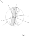
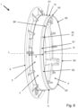
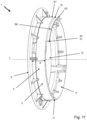
- Fig.2 deviates from the execution according to Fig.1 that the breakable second section A2 of the frame apron 3 has a single segmentation predetermined breaking point 30 which runs in the longitudinal direction L and divides the second section A2 in the circumferential direction of the frame apron 3, in particular such that the second section A2 is designed as an open ring or in circumferential segments (S1, S2, S3, S4, S5, S6, cf. Fig. 6 to 12 ) can be broken off, in particular irreversibly by breaking or breaking off.
- several segmentation predetermined breaking points 30 are evenly distributed over the circumference of the second section A2.
- the segmentation breaking points 30 each extend over the entire length between the first predetermined breaking point 10 and the end of the frame apron 3 which faces away from the closure element receptacle 2.
- the segmentation predetermined breaking points 30 each lie in a common plane with the longitudinal direction L or perpendicular to the first predetermined breaking point 10.
- the segmentation predetermined breaking points 30 are also each designed as a predetermined breaking groove 31 on the outside 5 of the frame apron 3.
- the predetermined breaking groove 31 of the segmentation predetermined breaking points 30 has a groove depth T3 which is at least 25%, and preferably at least 30%, of the wall thickness W of the frame apron 3 in the area of the predetermined breaking groove 31.
- this groove depth T3 of the predetermined breaking groove 31 of the segmentation predetermined breaking points 30 should be a maximum of 60%, and preferably a maximum of 50%, of the wall thickness W of the frame apron 3 in the area of the predetermined breaking groove 31.
- the predetermined breaking groove 31 of the segmentation predetermined breaking points 30 also has a rounded groove cross-section.
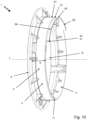
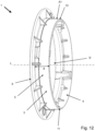
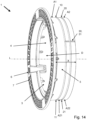
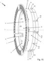
- the chess cover frames according to the Fig. 13 , 14 and 15 In this order, they essentially correspond to those in the Fig.1 , 2 and 3 are shown, which is why reference is first made to their description.
- the main difference in each case is that the frame apron 3 has a second predetermined breaking point 20 which runs transversely to the longitudinal direction L and divides the breakable second section A2 of the frame apron 3 into a breakable first partial section A21 and a breakable further partial section A22.
- the length X of the frame apron 3 can be shortened to two different values, in particular irreversibly by breaking off one or both partial sections A21, A22.
- the second predetermined breaking point 20 is located between the first predetermined breaking point 10 and the end of the frame apron 3 which faces away from the closure element holder 2.
- the second predetermined breaking point 20 is weaker than the first predetermined breaking point 10.
- the second predetermined breaking point 20 therefore breaks more easily than the first predetermined breaking point 10.
- the second predetermined breaking point 20 is designed as a predetermined breaking groove 21, which runs on the outside 5 of the frame apron 3 along the entire circumference of the frame apron 3.
- the predetermined breaking groove 21 of the second predetermined breaking point 20 also has a rounded groove cross-section.
- the predetermined breaking groove 21 of the second predetermined breaking point 20 has a groove depth T2 which is at least 25%, and preferably at least 30%, of the wall thickness W of the Frame apron 3 in the area of the predetermined breaking groove 21. It is clear that the wall thickness W decreases with increasing distance from the closure element holder 2. However, the groove depth T2 of the predetermined breaking groove 21 of the second predetermined breaking point 20 should be a maximum of 60%, and preferably a maximum of 50%, of the wall thickness W of the frame apron 3 in the area of this predetermined breaking groove 11. Furthermore, it can be seen that the first predetermined breaking point 10 is slightly weaker than the segmentation predetermined breaking point 30 in the adjacent area. Likewise, the second predetermined breaking point 20 is slightly weaker than the segmentation predetermined breaking point 30 in the adjacent area. This promotes straight crack formation along the first and/or second predetermined breaking point 10, 20.
- the Fig. 13 , 14 , 15 and 16 in each case that the at least one segmentation predetermined breaking point 30 extends over the entire length of the second section A2, thus flush over the first and the second partial section A21, A22, in the longitudinal direction L.
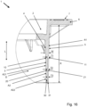
- Fig. 17 a longitudinal section through a shaft arrangement 90 with a shaft cover arrangement 80 on a shaft structure 91 is shown.
- the manhole cover arrangement 80 has a manhole cover frame 1, which, for example, as shown in the Fig. 1 to 16 A closure element 81 of the manhole cover arrangement 80 is inserted into the closure element receptacle 2 of the manhole cover frame 1 and thereby closes the manhole passage D.
- the manhole cover frame 1 is opposite the manhole structure 91 with the frame apron 3 and, if it were completely lowered, would sit on the manhole structure 91 and be supported on it. This is particularly the case because the frame apron 3 is longitudinally displaceable in a guide of a centering ring 92 of the manhole structure 91, the diameter of which is larger than the actual diameter of the manhole structure 91 at its upper end. The outer diameter of the frame apron 3 is therefore larger than the diameter of the manhole structure 91 below the centering ring 92.
- the manhole cover frame 1 To install the manhole cover frame 1, it is now first necessary to determine how high the available installation height for the manhole cover frame 1 is between the upper end of the manhole structure 91 and the desired installation height of the closure element holder 2 or the traffic area 7. The manhole cover frame 1 is then installed either without shortening the frame apron 3 if the available installation height is greater than a defined limit value. Alternatively, installation is only carried out after shortening the frame apron 3 in the longitudinal direction L by at least partially breaking off the second section A2 at a predetermined breaking point 10, 20 if the available Installation height is smaller than the defined limit. This can be done by hitting the outside 5 of the second section A2 with a hammer (see Fig. 1 to 16 ).
- Manhole cover frame A1 first section 2 Locking element holder A2 second part 3 Frame apron A21 first section 4 inside A22 further section 5 Outside D Shaft passage 6 Frame collar L Longitudinal direction 7 traffic area S1 Circumference segment S2 Circumference segment 10 first breaking point S3 Circumference segment 11 Breaking groove S4 Circumference segment S5 Circumference segment 20 second breaking point S6 Circumference segment 21 Breaking groove T1 Groove depth T2 Groove depth 30 Segmentation breaking point T3 Groove depth 31 Breaking groove W Wall thickness X length 80 Manhole cover arrangement 81 Locking element 90 Shaft arrangement 91 Shaft construction 92 Centering ring
Landscapes
- Engineering & Computer Science (AREA)
- Environmental & Geological Engineering (AREA)
- Life Sciences & Earth Sciences (AREA)
- General Life Sciences & Earth Sciences (AREA)
- Mining & Mineral Resources (AREA)
- Paleontology (AREA)
- Civil Engineering (AREA)
- General Engineering & Computer Science (AREA)
- Structural Engineering (AREA)
- Underground Structures, Protecting, Testing And Restoring Foundations (AREA)
Description
- Die Erfindung betrifft einen Schachtabdeckungsrahmen gemäß dem Oberbegriff von Anspruch 1, eine Schachtabdeckungsanordnung hiermit nach Anspruch 10, eine Schachtanordnung mit einer solchen Schachtabdeckungsanordnung nach Anspruch 11 und ein Verfahren zur Installation des Schachtabdeckungsrahmens nach Anspruch 12.
- Schachtabdeckungsanordnungen dienen der Abdeckung von Schächten und weisen meistens einen Schachtabdeckungsrahmen und ein Verschlusselement auf, mit dem eine Durchgangsöffnung in dem Schachtabdeckungsrahmen verschließbar ist. Solche Schachtabdeckungsrahmen werden insbesondere am oberen Ende eines Schachtaufbaus installiert. Insbesondere bei Schächten in Verkehrsflächen ist dabei eine bodengleiche Installation des Schachtabdeckungsrahmens und des Verschlusselements in der Verkehrsfläche notwendig.
- Problematisch ist im Stand der Technik, dass der Abstand zwischen dem Schachtaufbau und der Verkehrsfläche variabel ist. Soweit der Bauunternehmer im Voraus Kenntnis von diesem Abstand hat, kann er eine Schachtabdeckungsanordnung bestellen, die eine geeignete Länge aufweist. Selbst bei einer Vorplanung, insbesondere jedoch auch bei Sanierungen stellt sich auf der Baustelle jedoch oftmals heraus, dass die Aufbauhöhe der mitgeführten Schachtabdeckungsanordnung zu groß ist und bei einer Installation über die Verkehrsfläche hinausstehen würde. In der Praxis wird die Baustellentätigkeit dann bis zum Eintreffen einer kürzeren Schachtabdeckungsanordnung unterbrochen. Hierdurch entstehen Mehrkosten durch wiederholte Anfahrten, Bestellvorgänge und die Baustellenabsicherung. Außerdem wird der Verkehr auf der Verkehrsfläche für einen längeren Zeitraum behindert.
- Aus
DE 10 2015 106 750 A1 ist ein Schachtabdeckungsrahmen für eine Schachtabdeckungsanordnung zur Verwendung im Straßenneubau und in Sanierungsverfahren bekannt. Diese weist eine Rahmenschürze auf, durch die ein Schachtdurchgang verläuft. Außerdem verfügt der Schachtabdeckungsrahmen über eine Verschlusselementaufnahme. - In
US 6,311,433 B1 ist eine Schachtabdeckung bekannt, deren Rahmenschürze zweiteilig ausgebildet ist. Ein oberer Abschnitt der Rahmenschürze weist ein Innengewinde auf, mit dem er auf einen unteren Abschnitt mit einem Außengewinde aufgeschraubt ist. - Von
EP 0 953 687 A2 ist eine Vorrichtung zum Höhenausgleich zwischen Schachtabdeckung und Fahrbahnoberfläche beschrieben. -
EP 2 317 197 A1 gibt ein formstabiles Wasserrohr an, das eine Hülse mit einer Metallschicht und einer Kunststoffschicht aufweist. Diese Hülse weist Sollbruchstellen zum Ablängen auf. -
DE 9215759 U1 gibt eine Schachtabdeckung mit einem Schachtrahmen und einem aufklappbaren Schachtdeckel an. -
DE 10 2006 056 146 A1 gibt einen Einbaukörper für Bodenplatten von Gebäuden an, der eine Serviceöffnung zu einer Rohrleitung unter der Bodenplatte ausbildet, wie beispielhaft beschrieben zu einer Rückstauklappe. Dieser Einbaukörper weist einen vertikal ausgerichteten Durchgang auf, in den ein längliches, rechteckiges Aufsatzelement mit einem Anschlussstutzen eingesteckt ist. Dieses Aufsatzelement wird mit dem Anschlussstutzen (zusammen mit dem Einbaukörper) so in die Bodenplatte eingegossen, dass dessen Oberseite oberflächenbündig mit der Bodenplatte abschließt. Aufgrund unterschiedlicher Dicken der Bodenplatten und Abständen der unter der Bodenleitung liegenden Rohrleitung ist der Einsteckabschnitt kürzbar ausgestaltet. Dazu weist der Anschlussstutzen Ablängmarkierungen auf, an denen der Stutzen gemäßDE 10 2006 056 146 A1 abgesägt werden kann. Optional weist der Anschlussstutzen gemäßDE 10 2006 056 146 A1 zusätzlich eine einzige als Sollbruchstelle ausgebildete Ablängmarkierung auf. - Aufgabe der Erfindung ist es, eine Schachtabdeckungsanordnung, Einzelteile hiervon oder Verfahrensanweisungen bereitzustellen, mit denen die vorgenannten Nachteile überwunden werden, sodass mit der Installation der Schachtabdeckungsanordnung fortgefahren werden kann, ohne die Baustellentätigkeit unterbrechen zu müssen.
- Hauptmerkmale der Erfindung sind im kennzeichnenden Teil von Anspruch 1 sowie den Ansprüchen 10, 11 und 12 angegeben. Ausgestaltungen sind Gegenstand der Ansprüche 2 bis 8 sowie der Beschreibung.
- Die Erfindung betrifft einen Schachtabdeckungsrahmen für eine Schachtabdeckungsanordnung zur Verwendung im Straßenneubau und in Sanierungsverfahren, der einen in einer Längsrichtung verlaufenden Schachtdurchgang ausbildet, mit einer Verschlusselementaufnahme, insbesondere zur Aufnahme eines Verschlusselements einer Schachtabdeckungsanordnung mit dem der Schachtdurchgang verschließbar ist, und mit einer Rahmenschürze mit einer Innenseite, einer Außenseite und einer Länge in Längsrichtung, wobei der Schachtdurchgang durch die Rahmenschürze verläuft, wobei die Rahmenschürze eine erste Sollbruchstelle aufweist, die quer zur Längsrichtung verläuft, und die Rahmenschürze in einen ersten Abschnitt, der an die Verschlusselementaufnahme angrenzt, und einen gezielt entlang der ersten Sollbruchstelle abbrechbaren zweiten Abschnitt unterteilt, nämlich derart, dass die Länge der Rahmenschürze kürzbar ist, insbesondere irreversibel durch Bruchtrennen bzw. Abbrechen, wobei die erste Sollbruchstelle entlang des Umfangs der Rahmenschürze verläuft. Außerdem besteht der Schachtabdeckungsrahmen aus Gusseisen und die erste Sollbruchstelle ist zumindest abschnittsweise als Sollbruchnut ausgebildet, wobei die Rahmenschürze eine Wandstärke aufweist und die Sollbruchnut eine Nuttiefe hat, die wenigstens 25 % von der Wandstärke der Rahmenschürze im Bereich der Sollbruchnut beträgt.
- Vor Ort auf der Baustelle hat der Bauunternehmer mit diesem erfindungsgemäßen Schachtabdeckungsrahmen nunmehr die Möglichkeit, eine Anpassung der Länge des Schachtabdeckungsrahmens durch Kürzen der Rahmenschürze vorzunehmen, um diesen an den vorgefundenen Straßenaufbau anzupassen, ohne dass er hierzu die Baustelle verlassen müsste. Dies gelingt aufgrund der Sollbruchstelle insbesondere auch mit kostengünstigem und fast immer verfügbarem Werkzeug, z.B. einem Hammer, einem Spaten oder einer Spitzhacke. Dabei ist das Abschlagen auch sehr viel schneller, präziser und ungefährlicher als beispielsweise ein Abtrennen mit einem Trennschleifer. Das gezielte Abbrechen führt zu einer irreversiblen Teilung des Gesamtbauteils und basiert auf einem gezielten mechanischen Auslösen einer Rissbildung im Bereich der Sollbruchstelle, wobei der erste Abschnitt der Schachtabdeckungsrahmen alleine weiterverwendbar bleibt, insbesondere weil dieser erste Abschnitt nicht beschädigt wird.
- Dadurch, dass die erste Sollbruchstelle entlang des Umfangs der Rahmenschürze verläuft, lässt sich eine gleichmäßige Kürzung der Rahmenschürze über dem Umfang erzielen.
- Bei der erfindungsgemäßen Ausführungsform ist die erste Sollbruchstelle zumindest abschnittsweise als Sollbruchnut ausgebildet, wobei die Sollbruchnut vorzugsweise entlang des gesamten Umfangs der Rahmenschürze verläuft. Eine Sollbruchnut trägt zu einer sauberen Abbruchkante bei und ist einfach herstellbar. Damit wird insbesondere auch eine Beschädigung des ersten Abschnitts vermieden. Bei einem Verlauf über den gesamten Umfang ist auch die Abbruchkante über dem gesamten Umfang sauber definiert.
- Optional ist die Sollbruchnut auf der Außenseite der Rahmenschürze angeordnet. Dies trägt einerseits zu einer glatten Fläche auf der Innenseite der Rahmenschürze bei. Andererseits ist ein Schlag mit einem Werkzeug zur Auslösung eines Sollbruchs an der Sollbruchstelle auf der Außenseite leicht und präzise ausführbar.
- Gemäß der erfindungsgemäßen Ausführungsform weist die Rahmenschürze eine Wandstärke auf und die Sollbruchnut hat eine Nuttiefe, die wenigstens 25 %, und bevorzugt wenigstens 30 %, von der Wandstärke der Rahmenschürze im Bereich der Sollbruchnut beträgt. Damit ist die Rahmenschürze in diesem Bereich soweit gegenüber der angrenzenden Wandstärke der Rahmenschürze geschwächt, dass der Sollbruch sauber entlang der Sollbruchnut herstellbar ist. Dabei ist es von Vorteil, wenn die Nuttiefe maximal 60 %, und bevorzugt maximal 50 %, von der Wandstärke der Rahmenschürze im Bereich der Sollbruchnut beträgt. Damit ist der zweite Abschnitt noch vergleichsweise stabil mit dem ersten Abschnitt der Rahmenschürze verbunden und kann auch im ungekürzten Zustand Verkehrslasten abtragen.
- In einer speziellen Ausführungsform weist die Sollbruchnut einen rundlichen Nutquerschnitt auf. Durch das Fehlen von Ecken im Querschnittsprofil sind größere Verkehrslasten zwischen dem ersten und zweiten Abschnitt übertragbar, ohne dass es zu spontanen Materialbrüchen an der Sollbruchstelle kommt. Außerdem wird im Bereich des Nutbodens entlang einer Tangentenlinie eine minimale Wandstärke erreicht, entlang der sich der Sollbruch vollziehen lässt.
- Des Weiteren ist in einer optionalen Variante des Schachtabdeckungsrahmens vorgesehen, dass die Rahmenschürze wenigstens eine zweite Sollbruchstelle aufweist, die quer zur Längsrichtung verläuft und den abbrechbaren zweiten Abschnitt der Rahmenschürze in einen gezielt abbrechbaren ersten Teilabschnitt und einen gezielt abbrechbaren weiteren Teilabschnitt unterteilt, insbesondere derart, dass die Länge der Rahmenschürze gezielt auf zwei unterschiedliche Werte kürzbar ist, dies insbesondere irreversibel durch Bruchtrennen bzw. Abbrechen. Hierdurch entsteht für den Bauunternehmer eine besonders hohe Anpassungsfreiheit hinsichtlich der Länge der Rahmenschürze. Dabei sollte die wenigstens eine zweite Sollbruchstelle zwischen der ersten Sollbruchstelle und einem von der Verschlusselementaufnahme abgewandten Ende der Rahmenschürze angeordnet sein.
- Bei einer Ausführung mit wenigstens einer solchen zweiten Sollbruchstelle, ist eine Dimensionierung von Vorteil, gemäß der die zweite Sollbruchstelle schwächer ausgebildet ist als die erste Sollbruchstelle. Hierdurch lässt sich der Sollbruch an der zweiten Sollbruchstelle mit geringem Risiko der Auslösung eines Sollbruchs an der ersten Sollbruchstelle erzielen.
- Die zweite Sollbruchstelle kann optional die einzelnen optionalen Merkmale der ersten Sollbruchstelle aufweisen. Unter anderem kann die zweite Sollbruchstelle also optional entlang des Umfangs der Rahmenschürze verlaufen. Auch ist die zweite Sollbruchstelle zumindest abschnittsweise als Sollbruchnut ausbildbar. Dabei ist es vorteilhaft, wenn die Sollbruchnut der zweiten Sollbruchstelle auf der Außenseite der Rahmenschürze angeordnet ist. Hinsichtlich der Dimensionierung ist es zu bevorzugen, dass die Rahmenschürze eine Wandstärke aufweist und die Sollbruchnut der zweiten Sollbruchstelle eine Nuttiefe hat, die wenigstens 25 %, und bevorzugt wenigstens 30 %, der Wandstärke der Rahmenschürze im Bereich der Sollbruchnut beträgt. Als Obergrenze der Nuttiefe ist es günstig, wenn die Nuttiefe der Sollbruchnut der zweiten Sollbruchstelle maximal 60 %, und bevorzugt maximal 50 %, von der Wandstärke der Rahmenschürze im Bereich der Sollbruchnut beträgt. Schließlich kann optional vorgesehen sein, dass die Sollbruchnut der zweiten Sollbruchstelle einen rundlichen Nutquerschnitt aufweist. Hinsichtlich der Vorteile dieser optionalen Ausgestaltungen wird auf die vorhergehenden Abschnitte verwiesen, wo diese sinngemäß im Zusammenhang mit der ersten Sollbruchstelle dargestellt werden.
- Fernerhin ist in einer besonderen Ausgestaltung des Schachtabdeckungsrahmens vorgesehen, dass der abbrechbare zweite Abschnitt der Rahmenschürze wenigstens eine Segmentierungssollbruchstelle aufweist, die in Längsrichtung verläuft, und den zweiten Abschnitt bzw. zumindest einen von dessen Teilabschnitten in Umfangsrichtung der Rahmenschürze unterteilt, insbesondere derart, dass der zweite Abschnitt als offener Ring oder in Umfangssegmenten abbrechbar ist, insbesondere irreversibel durch Bruchtrennen bzw. Abbrechen. Wenn nur eine einzige Segmentierungssollbruchstelle vorgesehen ist, dient diese als Anfang des Sollbruches. Je nachdem wie spröde die Ringschürze ist, löst sich dann der gesamte offene Ring oder aber es werden Stück für Stück Segmente abgebrochen.
- Es ist vorteilhaft, wenn sich die wenigstens eine Segmentierungssollbruchstelle zwischen der ersten Sollbruchstelle und einem von der Verschlusselementaufnahme abgewandten Ende der Rahmenschürze erstreckt. Dabei kann sich die wenigstens eine Segmentierungssollbruchstelle entweder über die gesamte Länge des zweiten Abschnitts in Längsrichtung erstrecken oder aber über die gesamte Länge eines Teilabschnitts des zweiten Abschnitts in Längsrichtung erstrecken. Hierdurch bleiben die aneinandergrenzenden Teile des zweiten Abschnitts beim Abschlagen nicht aneinanderhängen.
- Besonders einfach ist das Abbrechen bzw. Bruchtrennen, wenn wenigstens zwei Segmentierungssollbruchstellen über den Umfang des zweiten Abschnitts verteilt angeordnet sind, vorzugsweise gleichverteilt. Hierdurch lassen sich die Segmente nämlich einfach einzeln abbrechen bzw. bruchtrennen. Weiterhin lässt sich der gesamte zweite Abschnitt besonders schnell vom ersten Abschnitt abtrennen, wenn die Segmentierungssollbruchstellen bei einer Unterteilung des zweiten Abschnitts in wenigstens zwei Teilabschnitte über die Grenzen der Teilabschnitte hinweg fluchtend angeordnet sind.
- Bevorzugt verlaufen die Segmentierungssollbruchstellen jeweils in einer gemeinsamen Ebene mit der Längsrichtung. Damit sind die längs ausgerichteten Bruchkanten beim Abrechen kurz.
- Die Segmentierungssollbruchstellen können optional die einzelnen optionalen Merkmale der ersten Sollbruchstelle aufweisen. Unter anderem können die Segmentierungssollbruchstellen also jeweils zumindest abschnittsweise als Sollbruchnut ausgebildet sein. Dabei ist es vorteilhaft, wenn die Sollbruchnut der Segmentierungssollbruchstellen jeweils auf der Außenseite der Rahmenschürze angeordnet ist. Hinsichtlich der Dimensionierung ist es zu bevorzugen, dass die Rahmenschürze eine Wandstärke aufweist und die Sollbruchnut der Segmentierungssollbruchstellen jeweils eine Nuttiefe haben, die wenigstens 25 %, und bevorzugt wenigstens 30 %, der Wandstärke der Rahmenschürze im Bereich der Sollbruchnut beträgt. Als Obergrenze der Nuttiefe, ist es günstig, wenn die Nuttiefe der Sollbruchnut der Segmentierungssollbruchstellen jeweils maximal 60 %, und bevorzugt maximal 50 %, von der Wandstärke der Rahmenschürze im Bereich der Sollbruchnut beträgt. Schließlich kann optional vorgesehen sein, dass die Sollbruchnut der Segmentierungssollbruchstellen jeweils einen rundlichen Nutquerschnitt aufweisen. Hinsichtlich der Vorteile dieser optionalen Ausgestaltungen wird auf die vorhergehenden Abschnitte verwiesen, wo diese sinngemäß im Zusammenhang mit der ersten Sollbruchstelle dargestellt werden.
- Weiterhin ist es zu bevorzugen, dass die Segmentierungssollbruchstellen stärker ausgebildet sind als die erste und/oder zweite Sollbruchstelle. Insbesondere sollte die Nuttiefe der Segmentierungssollbruchstellen weniger tief sein als die angrenzenden Sollbruchnuten der ersten und/oder zweiten Sollbruchstelle. Damit wird sich ein durch Abbrechen bzw. Bruchtrennen verursachter Riss bevorzugt entlang der ersten und/oder zweiten Sollbruchstelle fortsetzen. Eine gerade Abbruchkante wird hierdurch erzielt.
- Bei einer näheren Ausgestaltung des Schachtabdeckungsrahmens ist weiter vorgesehen, dass die Verschlusselementaufnahme einteilig mit der Rahmenschürze ausgebildet ist. Dies ist preiswert in der Herstellung und es wird eine hohe Stabilität erzielt. Bevorzugt ist der Schachtabdeckungsrahmen als solches einteilig ausgebildet. Hierzu kann auch ein Rahmenkragen gehören. Dieser kann radial über die Rahmenschürze hinausstehen. Außerdem kann er eine Verkehrsfläche ausbilden.
- Besonders stabil und gleichzeitig spröde genug zur Herstellung eines Sollbruches ist eine Variante, gemäß welcher die Rahmenschürze oder der Schachtabdeckungsrahmen aus Gusseisen besteht.
- Des Weiteren betrifft die Erfindung eine Schachtabdeckungsanordnung zur Verwendung im Straßenneubau und in Sanierungsverfahren, mit einem Schachtabdeckungsrahmen, wie er vor- und nachstehend beschrieben ist, und einem Verschlusselement, wobei der Schachtdurchgang durch die Positionierung des Verschlusselements an der Verschlusselementaufnahme verschließbar ist. Mithin lässt sich durch das Abbrechen bzw. Bruchtrennen nicht nur der Schachtabdeckungsrahmen nivellieren, sondern auch das Verschlusselement.
- Außerdem betrifft die Erfindung auch eine Schachtanordnung mit einer Schachtabdeckungsanordnung, wie sie vor- und nachstehend beschrieben ist, und einem Schachtaufbau, wobei der Schachtabdeckungsrahmen mit der Rahmenschürze in den Schachtaufbau hineinragt. Bei dieser Schachtanordnung ist es möglich, die Länge des Schachtabdeckungsrahmens, bzw. dessen Rahmenschürze, an die relative Position des Schachtaufbaus zur Verkehrsfläche anzupassen. Dabei kann die Rahmenschürze in einen Zentrierring des Schachtaufbaus eintauchen. Der Zentrierring bildet bevorzugt eine Führung für die Rahmenschürze aus. Vorzugsweise ist die Rahmenschürze längsverschieblich in dem Zentrierring gelagert. Hierdurch kann der Schachtabdeckungsrahmen in die Fahrbahndecke eingewalzt werden und nivelliert sich hierbei ein. Vor allem wenn die Rahmenschürze einen größeren Außendurchmesser hat als der Innendurchmesser des Schachtaufbaus an dessen oberen Ende beträgt, werden derartige Zentrierringe eingesetzt. Bei derartigen Durchmesserverhältnissen kann durch das Abbrechen des zweiten Abschnitts eine Kollision zwischen dem Schachtaufbau und der Rahmenschürze verhindert werden. Das Abbrechen des zweiten Abschnitts ist jedoch auch bei Ausgestaltungen sinnvoll, bei denen der Außendurchmesser der Rahmenschürze annähernd so groß ist wie der Innendurchmesser des Schachtaufbaus. Bei einem tiefen Eintauchen der Rahmenschürze in den Schachtaufbau kann es nämlich insbesondere bei schräg zum Schachtaufbau ausgerichteten Verkehrsflächen zu einem Verklemmen kommen, was schlimmstenfalls zu einer Beschädigung des Schachtaufbaus führt. Dies lässt sich durch Kürzen der Rahmenschürze vermeiden.
- Der Schachtaufbau kann insbesondere eine kreisförmige Öffnung für die Rahmenschürze ausbilden. Entsprechend sollte auch die Rahmenschürze eine im Wesentlichen zylindrische Außenfläche haben. Des Weiteren besteht der erfindungsgemäße Schachtaufbau vorzugsweise im Wesentlichen aus Beton. Dabei kann der optionale Zentrierring jedoch aus Beton oder auch aus Metall, z.B. Gusseisen bestehen.
- Schließlich betrifft die Erfindung auch noch ein Verfahren zur Installation eines Schachtabdeckungsrahmens, wie er vor- und nachstehend beschrieben ist, auf einem Schachtaufbau, das die folgenden Schritte umfasst. Zunächst wird eine verfügbare Aufbauhöhe für den Schachtabdeckungsrahmen zwischen einem oberen Ende des Schachtaufbaus und der gewünschten Einbauhöhe der Verschlusselementaufnahme bestimmt. Anschließend wird der Schachtabdeckungsrahmen entweder ohne Kürzen der Rahmenschürze eingebaut, wenn die verfügbare Aufbauhöhe größer ist als ein definierter Grenzwert, oder erst nach dem Kürzen der Rahmenschürze in Längsrichtung durch zumindest teilweises Abbrechen des zweiten Abschnitts an einer Sollbruchstelle eingebaut, wenn die verfügbare Aufbauhöhe kleiner ist als der definierte Grenzwert. Damit lässt sich die Länge der Schachtabdeckungsanordnung schnell und kostengünstig auf der Baustelle anpassen.
- Besonders vorteilhaft ist es, wenn das Abbrechen durch Schlagen auf den zweiten Abschnitt mit einem Schlagwerkzeug erfolgt, insbesondere mit einem Hammer (z.B. ein Fäustel). Solche sind fast immer verfügbar. Mit der Handhabung von Hämmern sind Bauarbeiter außerdem bestens vertraut und ein Hammer wird auch fast immer mitgeführt. Hilfsweise lässt sich schnell ein Hammer besorgen. Die Sollbruchstellen sollten also für das Abbrechen mit einem Schlagwerkzeug ausgelegt sein.
- Weitere Merkmale, Einzelheiten und Vorteile der Erfindung ergeben sich aus dem Wortlaut der Ansprüche sowie aus der folgenden Beschreibung von Ausführungsbeispielen anhand der Zeichnungen. Es zeigen:
- Fig. 1
- eine perspektivische Ansicht eines Schachtabdeckungsrahmens mit einer ersten Sollbruchstelle;
- Fig. 2
- eine perspektivische Ansicht eines Schachtabdeckungsrahmens mit einer ersten Sollbruchstelle und einer einzigen Segmentierungssollbruchstelle;
- Fig. 3
- eine perspektivische Ansicht eines Schachtabdeckungsrahmens mit einer ersten Sollbruchstelle und mehreren Segmentierungssollbruchstellen;
- Fig. 4
- einen Längsschnitt durch einen Schachtabdeckungsrahmen, in dem eine erste Sollbruchstelle und eine einzige Segmentierungssollbruchstelle erkennbar sind;
- Fig. 5
- einen Querschnitt durch einen Schachtabdeckungsrahmen, in dem eine einzige Segmentierungssollbruchstelle erkennbar ist;
- Fig. 6 bis 12
- eine perspektivische Ansicht des Schachtabdeckungsrahmens nach
Fig. 1 , wobei ein zweiter Abschnitt der Rahmenschürze in der Figurenreihenfolge schrittweise weiter abgebrochen ist; - Fig. 13
- eine perspektivische Ansicht eines Schachtabdeckungsrahmens mit einer ersten und einer zweiten Sollbruchstelle;
- Fig. 14
- eine perspektivische Ansicht eines Schachtabdeckungsrahmens mit einer ersten und einer zweiten Sollbruchstelle sowie einer einzigen Segmentierungssollbruchstelle;
- Fig. 15
- eine perspektivische Ansicht eines Schachtabdeckungsrahmens mit einer ersten und einer zweiten Sollbruchstelle sowie mehreren Segmentierungssollbruchstellen;
- Fig. 16
- einen Längsschnitt durch einen Schachtabdeckungsrahmen, in dem eine erste und eine zweite Sollbruchstelle sowie eine Segmentierungssollbruchstelle erkennbar sind; und
- Fig. 17
- einen Längsschnitt durch einen Schachtaufbau mit einem Schachtabdeckungsrahmen.
- Die
Fig. 1 bis 3 zeigen jeweils in einer perspektivischen Ansicht einen Schachtabdeckungsrahmen 1 für eine Schachtabdeckungsanordnung (80, vgl.Fig. 17 ) zur Verwendung im Straßenneubau und in Sanierungsverfahren. Dieser bildet einen in einer Längsrichtung L verlaufenden Schachtdurchgang D aus. Oberseitig verfügt der Schachtabdeckungsrahmen 1 über eine Verschlusselementaufnahme 2 zur Aufnahme eines Verschlusselements (81, vgl.Fig. 17 ) einer Schachtabdeckungsanordnung (80, vgl.Fig. 17 ) mit dem der Schachtdurchgang D verschließbar ist. Die Verschlusselementaufnahme 2 ist radial von einem Rahmenkragen 6 eingefasst, der eine oberseitige Verkehrsfläche 7 ausbildet. - An die Verschlusselementaufnahme 2 schließt sich in Längsrichtung L eine rohrförmige Rahmenschürze 3 mit einer Innenseite 4, einer Außenseite 5 und einer Länge X in Längsrichtung L an. Der Rahmenkragen 6 steht radial über die Rahmenschürze 3 hinaus. Der Schachtdurchgang D verläuft sowohl durch diese Rahmenschürze 3 als auch die Verschlusselementaufnahme 2 und den Rahmenkragen 6.
- Der Schachtabdeckungsrahmen 1 ist einteilig aus Gusseisen ausgebildet, insbesondere inklusive der Verschlusselementaufnahme 2, dem Rahmenkragen 6 und der Rahmenschürze 3.
- Weiterhin erkennt man in den
Fig. 1 bis 3 jeweils, dass die Rahmenschürze 3 eine erste Sollbruchstelle 10 aufweist, die quer zur Längsrichtung L verläuft, und die Rahmenschürze 3 in einen ersten Abschnitt A1, der an die Verschlusselementaufnahme 2 angrenzt, und einen abbrechbaren zweiten Abschnitt A2 unterteilt. Hierdurch ist die Länge X der Rahmenschürze 3 kürzbar, insbesondere irreversibel durch Bruchtrennen bzw. Abbrechen. Die erste Sollbruchstelle 10 ist als Sollbruchnut 11 auf der Außenseite 5 der Rahmenschürze 3 ausgebildet, die entlang des gesamten Umfangs der Rahmenschürze 3 verläuft. - Im Längsschnitt durch den Schachtabdeckungsrahmen 1 nach
Fig. 4 erkennt man, dass die Rahmenschürze 3 eine Wandstärke W aufweist und die Sollbruchnut 11 eine Nuttiefe T1 hat, die wenigstens 25 %, und bevorzugt wenigstens 30 %, von der Wandstärke W der Rahmenschürze 3 im Bereich der Sollbruchnut 11 beträgt. Diese Nuttiefe T1 sollte jedoch maximal 60 %, und bevorzugt maximal 50 %, von der Wandstärke W der Rahmenschürze 3 im Bereich der Sollbruchnut 11 betragen. Wie man außerdem sieht, weist die Sollbruchnut 11 einen rundlichen Nutquerschnitt auf. Der Längsschnitt nachFig. 4 zeigt insbesondere einen Schnitt durch einen Schachtabdeckungsrahmen 1 nach denFig. 2 oder3 , weswegen bezüglich des weiteren Aufbaus des Schachtabdeckungsrahmen 1 auf deren Beschreibung verwiesen wird. -
Fig. 2 weicht insofern von der Ausführung nachFig. 1 ab, dass der abbrechbare zweite Abschnitt A2 der Rahmenschürze 3 eine einzige Segmentierungssollbruchstelle 30 aufweist, die in Längsrichtung L verläuft, und den zweiten Abschnitt A2 in Umfangsrichtung der Rahmenschürze 3 unterteilt, insbesondere derart, dass der zweite Abschnitt A2 als offener Ring oder in Umfangssegmenten (S1, S2, S3, S4, S5, S6, vgl.Fig. 6 bis 12 ) abbrechbar ist, insbesondere irreversibel durch Bruchtrennen bzw. Abbrechen . Abweichend hierzu sind in der Ausführung nachFig. 3 mehrere Segmentierungssollbruchstellen 30 gleichverteilt über den Umfang des zweiten Abschnitts A2 verteilt angeordnet. - Die Segmentierungssollbruchstellen 30 nach den
Fig. 2 und3 erstrecken sich jeweils über die gesamte Länge zwischen der ersten Sollbruchstelle 10 und dem Ende der Rahmenschürze 3, das von der Verschlusselementaufnahme 2 abgewandt ist. Die Segmentierungssollbruchstellen 30 liegen jeweils in einer gemeinsamen Ebene mit der Längsrichtung L bzw. senkrecht zur ersten Sollbruchstelle 10. Auch die Segmentierungssollbruchstellen 30 sind jeweils als Sollbruchnut 31 auf der Außenseite 5 der Rahmenschürze 3 ausgebildet. - Im Querschnitt gemäß
Fig. 5 weist die Sollbruchnut 31 der Segmentierungssollbruchstellen 30 eine Nuttiefe T3 auf, die wenigstens 25 %, und bevorzugt wenigstens 30 %, der Wandstärke W der Rahmenschürze 3 im Bereich der Sollbruchnut 31 beträgt. Diese Nuttiefe T3 der Sollbruchnut 31 der Segmentierungssollbruchstellen 30 sollte allerdings maximal 60 %, und bevorzugt maximal 50 %, von der Wandstärke W der Rahmenschürze 3 im Bereich der Sollbruchnut 31 betragen. Erkennbar verfügt auch die Sollbruchnut 31 der Segmentierungssollbruchstellen 30 jeweils über einen rundlichen Nutquerschnitt. Im Weiteren wird bezüglich der gekennzeichneten technischen Merkmale auf die Beschreibung derFig. 2 ,3 und4 verwiesen. - In den
Fig. 6 bis 12 ist nunmehr in der Bildreihenfolge gezeigt, wie der ringförmige zweite Abschnitt A2 gemäßFig. 2 ausgehend von der ersten Sollbruchnut 31 segmentweise durch Abbrechen von sechs Umfangssegmenten S1, S2, S3, S4, S5, S6 abgebrochen wird. Die Anzahl und Länge der Segmente ist dabei von der Abbruchausführung abhängig, denn ausgehend von der ersten Sollbruchnut 31 bricht der offene Ring des zweiten Abschnitts A2 beim Abrechen spontan in Segmente. Bei einer Ausführung nachFig. 3 würde es tendenziell direkt an der benachbarten Sollbruchnut 31 zu einem Abrechen kommen, sodass die Umfangssegmente definierte Längen hätten. - Die Schachabdeckungsrahmen gemäß den
Fig. 13 ,14 und15 entsprechen in dieser Reihenfolge im Wesentlichen denjenigen, die in denFig. 1 ,2 und3 gezeigt sind, weswegen zunächst auf deren Beschreibung verwiesen wird. Hauptunterschied ist jeweils, dass die Rahmenschürze 3 eine zweite Sollbruchstelle 20 aufweist, die quer zur Längsrichtung L verläuft und den abbrechbaren zweiten Abschnitt A2 der Rahmenschürze 3 in einen abbrechbaren ersten Teilabschnitt A21 und einen abbrechbaren weiteren Teilabschnitt A22 unterteilt. Dadurch ist die Länge X der Rahmenschürze 3 auf zwei unterschiedliche Werte kürzbar, insbesondere irreversibel durch Abbrechen eines oder beider Teilabschnitte A21, A22. Die zweite Sollbruchstelle 20 liegt zwischen der ersten Sollbruchstelle 10 und dem Ende der Rahmenschürze 3, das von der Verschlusselementaufnahme 2 abgewandt ist. - Wie man insbesondere in der Längsschnittdarstellung der Ausführung nach den
Fig. 14 oder15 inFig. 16 sieht, ist die zweite Sollbruchstelle 20 schwächer ausgebildet als die erste Sollbruchstelle 10. Damit bricht die zweite Sollbruchstelle 20 leichter als die erste Sollbruchstelle 10. Hierzu ist die zweite Sollbruchstelle 20 als Sollbruchnut 21 ausgebildet, die auf der Außenseite 5 der Rahmenschürze 3 entlang des gesamten Umfangs der Rahmenschürze 3 verläuft. Auch die Sollbruchnut 21 der zweiten Sollbruchstelle 20 hat einen rundlichen Nutquerschnitt. Die Sollbruchnut 21 der zweiten Sollbruchstelle 20 hat eine Nuttiefe T2, die wenigstens 25 %, und bevorzugt wenigstens 30 %, der Wandstärke W der Rahmenschürze 3 im Bereich der Sollbruchnut 21 beträgt. Erkennbar nimmt die Wandstärke W mit zunehmendem Abstand von der Verschlusselementaufnahme 2 ab. Die Nuttiefe T2 der Sollbruchnut 21 der zweiten Sollbruchstelle 20 sollte jedoch maximal 60 %, und bevorzugt maximal 50 %, von der Wandstärke W der Rahmenschürze 3 im Bereich dieser Sollbruchnut 11 betragen. Des Weiteren erkennt man, dass die erste Sollbruchstelle 10 geringfügig schwächer ist als die Segmentierungssollbruchstelle 30 im angrenzenden Bereich. Gleichermaßen ist die zweite Sollbruchstelle 20 geringfügig schwächer als die Segmentierungssollbruchstelle 30 im angrenzenden Bereich. Dies begünstigt eine gerade Rissbildung entlang der ersten und/oder zweiten Sollbruchstelle 10, 20. - Weiterhin geht aus den
Fig. 13 ,14 ,15 und16 jeweils hervor, dass sich die wenigstes eine Segmentierungssollbruchstelle 30 über die gesamte Länge des zweiten Abschnitts A2, mithin fluchtend über den ersten und den zweiten Teilabschnitt A21, A22, in Längsrichtung L erstreckt. - In
Fig. 17 ist ein Längsschnitt durch eine Schachtanordnung 90 mit einer Schachtabdeckungsanordnung 80 auf einem Schachtaufbau 91 gezeigt. - Die Schachtabdeckungsanordnung 80 weist einen Schachtabdeckungsrahmen 1 auf, der beispielsweise wie in den
Fig. 1 bis 16 ausgestaltet sein kann. Ein Verschlusselement 81 der Schachtabdeckungsanordnung 80 ist in die Verschlusselementaufnahme 2 des Schachtabdeckungsrahmens 1 eingelegt und verschließt hierdurch den Schachtdurchgang D. - Der Schachtabdeckungsrahmen 1 steht dem Schachtaufbau 91 mit der Rahmenschürze 3 gegenüber, und würde, wenn er komplett abgesenkt würde auf dem Schachtaufbau 91 sitzen und sich auf diesem abstützen. Dies ist insbesondere der Fall, weil die Rahmenschürze 3 längsverschiebbar in einer Führung eines Zentrierrings 92 des Schachtaufbaus 91 sitzt, dessen Durchmesser größer ist als der eigentliche Durchmesser des Schachtaufbaus 91 an seinem oberen Ende. Der Außendurchmesser der Rahmenschürze 3 ist also größer als der Durchmesser des Schachtaufbaus 91 unterhalb des Zentrierrings 92.
- Zur Installation des Schachtabdeckungsrahmens 1 kann nunmehr zunächst bestimmt werden, wie hoch die verfügbare Aufbauhöhe für den Schachtabdeckungsrahmen 1 zwischen dem oberen Ende des Schachtaufbaus 91 und der gewünschten Einbauhöhe der Verschlusselementaufnahme 2 bzw. der Verkehrsfläche 7 ist. Anschließend wird der Schachtabdeckungsrahmens 1 entweder ohne Kürzen der Rahmenschürze 3 eingebaut, wenn die verfügbare Aufbauhöhe größer ist als ein definierter Grenzwert. Alternativ erfolgt der Einbau erst nach einem Kürzen der Rahmenschürze 3 in Längsrichtung L durch zumindest teilweises Abbrechen des zweiten Abschnitts A2 an einer Sollbruchstelle 10, 20, wenn die verfügbare Aufbauhöhe kleiner ist als der definierte Grenzwert. Hierzu kann beispielsweise mit einem Hammer auf die Außenseite 5 des zweiten Abschnitts A2 geschlagen werden (siehe
Fig. 1 bis 16 ). -
1 Schachtabdeckungsrahmen A1 erster Abschnitt 2 Verschlusselementaufnahme A2 zweiter Abschnitt 3 Rahmenschürze A21 erster Teilabschnitt 4 Innenseite A22 weiterer Teilabschnitt 5 Außenseite D Schachtdurchgang 6 Rahmenkragen L Längsrichtung 7 Verkehrsfläche S1 Umfangssegment S2 Umfangssegment 10 erste Sollbruchstelle S3 Umfangssegment 11 Sollbruchnut S4 Umfangssegment S5 Umfangssegment 20 zweite Sollbruchstelle S6 Umfangssegment 21 Sollbruchnut T1 Nuttiefe T2 Nuttiefe 30 Segmentierungssollbruchstelle T3 Nuttiefe 31 Sollbruchnut W Wandstärke X Länge 80 Schachtabdeckungsanordnung 81 Verschlusselement 90 Schachtanordnung 91 Schachtaufbau 92 Zentrierring
Claims (12)
- Schachtabdeckungsrahmen (1) für eine Schachtabdeckungsanordnung (80) zur Verwendung im Straßenneubau und in Sanierungsverfahren, der einen in einer Längsrichtung (L) verlaufenden Schachtdurchgang (D) ausbildet,- mit einer Verschlusselementaufnahme (2), und- mit einer Rahmenschürze (3) mit einer Innenseite (4), einer Außenseite (5) und einer Länge (X) in Längsrichtung (L), wobei der Schachtdurchgang (D) durch die Rahmenschürze (3) verläuft,- wobei der Schachtabdeckungsrahmen (1) aus Gusseisen besteht, dadurch gekennzeichnet, dassdie Rahmenschürze (3) eine erste Sollbruchstelle (10) aufweist, die quer zur Längsrichtung (L) verläuft, und die Rahmenschürze (3) in einen ersten Abschnitt (A1), der an die Verschlusselementaufnahme (2) angrenzt, und einen gezielt entlang der ersten Sollbruchstelle (10) abbrechbaren zweiten Abschnitt (A2) derart unterteilt, dass die Länge der Rahmenschürze kürzbar ist, wobei die erste Sollbruchstelle (10) entlang des Umfangs der Rahmenschürze (3) verläuft, und die erste Sollbruchstelle (10) zumindest abschnittsweise als Sollbruchnut (11) ausgebildet ist, wobei die Rahmenschürze (3) eine Wandstärke (W) aufweist und die Sollbruchnut (11) eine Nuttiefe (T1) hat, die wenigstens 25 % von der Wandstärke (W) der Rahmenschürze (3) im Bereich der Sollbruchnut (11) beträgt.
- Schachtabdeckungsrahmen (1) nach Anspruch 1, dadurch gekennzeichnet, dass die Rahmenschürze (3) wenigstens eine zweite Sollbruchstelle (20) aufweist, die quer zur Längsrichtung (L) verläuft und den abbrechbaren zweiten Abschnitt (A2) der Rahmenschürze (3) in einen gezielt abbrechbaren ersten Teilabschnitt (A21) und einen gezielt abbrechbaren weiteren Teilabschnitt (A22) unterteilt.
- Schachtabdeckungsrahmen (1) nach Anspruch 2, dadurch gekennzeichnet, dass die zweite Sollbruchstelle (20) schwächer ausgebildet ist als die erste Sollbruchstelle (10).
- Schachtabdeckungsrahmen (1) nach einem der vorhergehenden Ansprüche, dadurch gekennzeichnet, dass der abbrechbare zweite Abschnitt (A2) der Rahmenschürze (3) wenigstens eine Segmentierungssollbruchstelle (30) aufweist, die in Längsrichtung (L) verläuft, und den zweiten Abschnitt (A2) in Umfangsrichtung der Rahmenschürze (3) unterteilt.
- Schachtabdeckungsrahmen (1) nach einem der vorhergehenden Ansprüche, dadurch gekennzeichnet, dass die Sollbruchnut (11) auf der Außenseite (5) der Rahmenschürze (3) angeordnet ist.
- Schachtabdeckungsrahmen (1) nach einem der vorhergehenden Ansprüche, dadurch gekennzeichnet, dass die Sollbruchnut (11) einen rundlichen Nutquerschnitt aufweist.
- Schachtabdeckungsrahmen (1) nach einem der vorhergehenden Ansprüche, dadurch gekennzeichnet, dass die Verschlusselementaufnahme (2) einteilig mit der Rahmenschürze (3) ausgebildet ist.
- Schachtabdeckungsrahmen (1) nach einem der vorhergehenden Ansprüche, dadurch gekennzeichnet, dass dieser einteilig ausgebildet ist.
- Schachtabdeckungsrahmen (1) nach einem der vorhergehenden Ansprüche, dadurch gekennzeichnet, dass die Sollbruchstelle (10) für das Abbrechen mit einem Schlagwerkzeug ausgelegt ist.
- Schachtabdeckungsanordnung (80) zur Verwendung im Straßenneubau und in Sanierungsverfahren, mit einem Schachtabdeckungsrahmen (1) nach einem der vorhergehenden Ansprüche und einem Verschlusselement (81), wobei der Schachtdurchgang (D) durch die Positionierung des Verschlusselements (81) an der Verschlusselementaufnahme (2) verschließbar ist.
- Schachtanordnung (90) mit einer Schachtabdeckungsanordnung (80) nach Anspruch 10 und einem Schachtaufbau (91), wobei der Schachtabdeckungsrahmen (1) mit der Rahmenschürze (3) in den Schachtaufbau (91) hineinragt.
- Verfahren zur Installation eines Schachtabdeckungsrahmens (1) nach einem der Ansprüche 1 bis 9 auf einem Schachtaufbau (91), umfassend die folgenden Schritte:a) Bestimmen einer verfügbaren Aufbauhöhe für den Schachtabdeckungsrahmen (1) zwischen einem oberen Ende des Schachtaufbaus (91) und der gewünschten Einbauhöhe der Verschlusselementaufnahme (2);b) Einbau des Schachtabdeckungsrahmens (1) ohne Kürzen der Rahmenschürze (3), wenn die verfügbare Aufbauhöhe größer ist als ein definierter Grenzwert;c) Einbau des Schachtabdeckungsrahmens (1) nach Kürzen der Rahmenschürze (3) in Längsrichtung (L) durch zumindest teilweises Abbrechen des zweiten Abschnitts (A2) an einer der Sollbruchstellen (10, 20), wenn die verfügbare Aufbauhöhe kleiner ist als der definierte Grenzwert.
Applications Claiming Priority (1)
| Application Number | Priority Date | Filing Date | Title |
|---|---|---|---|
| DE102018109220.2A DE102018109220A1 (de) | 2018-04-18 | 2018-04-18 | Schachtabdeckungsrahmen, Schachtabdeckungsanordnung, Schachtanordnung und Installationsverfahren |
Publications (2)
| Publication Number | Publication Date |
|---|---|
| EP3556944A1 EP3556944A1 (de) | 2019-10-23 |
| EP3556944B1 true EP3556944B1 (de) | 2024-05-01 |
Family
ID=65904196
Family Applications (1)
| Application Number | Title | Priority Date | Filing Date |
|---|---|---|---|
| EP19164383.2A Active EP3556944B1 (de) | 2018-04-18 | 2019-03-21 | Schachtabdeckungsrahmen, schachtabdeckungsanordnung, schachtanordnung und installationsverfahren |
Country Status (3)
| Country | Link |
|---|---|
| EP (1) | EP3556944B1 (de) |
| DE (2) | DE102018109220A1 (de) |
| PL (1) | PL3556944T3 (de) |
Families Citing this family (1)
| Publication number | Priority date | Publication date | Assignee | Title |
|---|---|---|---|---|
| CN115110911B (zh) * | 2022-07-14 | 2024-05-14 | 东营大明石油工程科技开发有限责任公司 | 一种井口对接装置及其对接方法 |
Citations (2)
| Publication number | Priority date | Publication date | Assignee | Title |
|---|---|---|---|---|
| US6311433B1 (en) * | 2000-09-05 | 2001-11-06 | David J. Zdroik | Adjustable manhole/catch basin structure |
| DE102006056146A1 (de) * | 2006-11-28 | 2008-06-05 | Aco Severin Ahlmann Gmbh & Co. Kg | Vorrichtung zum Einbau in eine Rohrleitung |
Family Cites Families (4)
| Publication number | Priority date | Publication date | Assignee | Title |
|---|---|---|---|---|
| DE9215759U1 (de) | 1992-11-20 | 1993-03-04 | Passavant-Werke AG, 6209 Aarbergen | Aus Rahmen und klappbarem Deckel oder Rost bestehender Kanalisationsartikel |
| EP0953687B1 (de) | 1998-04-30 | 2006-08-16 | Gerhard Schone | Vorrichtung zum Höhenausgleich zwischen Schachthals und Fahrbahnoberfläche und Anordnung der Vorrichtung in einer Fahrbahnkonstruktion |
| EP2317197B1 (de) | 2009-11-02 | 2012-06-06 | R. Nussbaum AG | Formstabiles Rohr zum Führen von Wasser |
| DE102015106750A1 (de) | 2015-04-30 | 2016-11-03 | ACO Severin Ahlmann GmbH & Co Kommanditgesellschaft | Schachtabdeckung |
-
2018
- 2018-04-18 DE DE102018109220.2A patent/DE102018109220A1/de not_active Withdrawn
-
2019
- 2019-03-21 DE DE202019005915.6U patent/DE202019005915U1/de active Active
- 2019-03-21 PL PL19164383.2T patent/PL3556944T3/pl unknown
- 2019-03-21 EP EP19164383.2A patent/EP3556944B1/de active Active
Patent Citations (2)
| Publication number | Priority date | Publication date | Assignee | Title |
|---|---|---|---|---|
| US6311433B1 (en) * | 2000-09-05 | 2001-11-06 | David J. Zdroik | Adjustable manhole/catch basin structure |
| DE102006056146A1 (de) * | 2006-11-28 | 2008-06-05 | Aco Severin Ahlmann Gmbh & Co. Kg | Vorrichtung zum Einbau in eine Rohrleitung |
Also Published As
| Publication number | Publication date |
|---|---|
| PL3556944T3 (pl) | 2024-10-28 |
| DE102018109220A1 (de) | 2019-10-24 |
| DE202019005915U1 (de) | 2023-04-05 |
| EP3556944A1 (de) | 2019-10-23 |
Similar Documents
| Publication | Publication Date | Title |
|---|---|---|
| EP2839083B1 (de) | Rammspitze für pfahl | |
| EP0173227A2 (de) | Verankerungselement für die Befestigung von Steigvorrichtungen in Wandflächen | |
| EP3556944B1 (de) | Schachtabdeckungsrahmen, schachtabdeckungsanordnung, schachtanordnung und installationsverfahren | |
| EP3115511A1 (de) | Verfahren zur herstellung einer überschnittenen bohrpfahlwand | |
| EP2631370B1 (de) | Unterflur-Schacht | |
| DE202010004381U1 (de) | Druckrohr sowie daraus hergestellter Erdanker | |
| EP2902645B1 (de) | Schraube zum Einschrauben in ein Bohrloch und Vorspann-Anordnung mit einer derartigen in das Bohrloch eingeschraubten Schraube | |
| WO2013026510A1 (de) | Pfahl | |
| EP1460277B1 (de) | Verankerungshülse für Schutzgeländer | |
| DE202021003948U1 (de) | Baugruppe zur Ausbildung einer Sollbruchstelle am Pfahlkopf eines Ortbetonpfahls | |
| EP0262444A1 (de) | Verankerungselement, insbesondere Dübel | |
| DE202014100247U1 (de) | Brunnenrohr zur Verbindung mit Grundwasser führenden Erdschichten, insbesondere zum Einsatz bei Wärmepumpensystemen | |
| DE102013015502B4 (de) | Verfahren zum baulich lntegrieren eines Aufsetzstücks gemeinsam mit einer Leitung in ein Wand- oder Bodenelement | |
| CH711156B1 (de) | Anschlagelement, Positioniervorrichtung mit mindestens einem solchen Anschlagelement und Verfahren zur Positionierung von Wandschalungen. | |
| EP0315277A1 (de) | Verfahren und Vorrichtung zur Prüfung von erdverlegten Kanalisationsrohren aus Beton | |
| EP3107166B1 (de) | Durchführung zum hindurchführen einer leitung durch ein wand- oder bodenelement | |
| EP3228750B1 (de) | Verfahren und bodendübelsystem zur pfostenbefestigung | |
| DE202015004654U1 (de) | Durchführung zum Hindurchführen einer Leitung durch ein Wand- oder Bodenelement | |
| EP3296045A1 (de) | Bohrer | |
| AT516176B1 (de) | Seitenwandung für eine Überlaufrinne | |
| DE10124171A1 (de) | Schutzwand für Straßen | |
| DE2730019A1 (de) | Revisions- und/oder kontrollschacht fuer kanalsysteme | |
| DE9307284U1 (de) | Verschlußteil für Betonwand oder Betondecke | |
| EP3784835B1 (de) | Anschlussvorrichtung, ablaufsystem und verfahren | |
| DE29611837U1 (de) | Vorrichtung zum Versetzen von Kellerfenstergewänden |
Legal Events
| Date | Code | Title | Description |
|---|---|---|---|
| PUAI | Public reference made under article 153(3) epc to a published international application that has entered the european phase |
Free format text: ORIGINAL CODE: 0009012 |
|
| STAA | Information on the status of an ep patent application or granted ep patent |
Free format text: STATUS: THE APPLICATION HAS BEEN PUBLISHED |
|
| AK | Designated contracting states |
Kind code of ref document: A1 Designated state(s): AL AT BE BG CH CY CZ DE DK EE ES FI FR GB GR HR HU IE IS IT LI LT LU LV MC MK MT NL NO PL PT RO RS SE SI SK SM TR |
|
| AX | Request for extension of the european patent |
Extension state: BA ME |
|
| STAA | Information on the status of an ep patent application or granted ep patent |
Free format text: STATUS: REQUEST FOR EXAMINATION WAS MADE |
|
| 17P | Request for examination filed |
Effective date: 20200410 |
|
| RBV | Designated contracting states (corrected) |
Designated state(s): AL AT BE BG CH CY CZ DE DK EE ES FI FR GB GR HR HU IE IS IT LI LT LU LV MC MK MT NL NO PL PT RO RS SE SI SK SM TR |
|
| STAA | Information on the status of an ep patent application or granted ep patent |
Free format text: STATUS: EXAMINATION IS IN PROGRESS |
|
| 17Q | First examination report despatched |
Effective date: 20211012 |
|
| GRAP | Despatch of communication of intention to grant a patent |
Free format text: ORIGINAL CODE: EPIDOSNIGR1 |
|
| STAA | Information on the status of an ep patent application or granted ep patent |
Free format text: STATUS: GRANT OF PATENT IS INTENDED |
|
| INTG | Intention to grant announced |
Effective date: 20240112 |
|
| GRAS | Grant fee paid |
Free format text: ORIGINAL CODE: EPIDOSNIGR3 |
|
| GRAA | (expected) grant |
Free format text: ORIGINAL CODE: 0009210 |
|
| STAA | Information on the status of an ep patent application or granted ep patent |
Free format text: STATUS: THE PATENT HAS BEEN GRANTED |
|
| AK | Designated contracting states |
Kind code of ref document: B1 Designated state(s): AL AT BE BG CH CY CZ DE DK EE ES FI FR GB GR HR HU IE IS IT LI LT LU LV MC MK MT NL NO PL PT RO RS SE SI SK SM TR |
|
| REG | Reference to a national code |
Ref country code: GB Ref legal event code: FG4D Free format text: NOT ENGLISH |
|
| REG | Reference to a national code |
Ref country code: CH Ref legal event code: EP |
|
| REG | Reference to a national code |
Ref country code: DE Ref legal event code: R096 Ref document number: 502019011155 Country of ref document: DE |
|
| REG | Reference to a national code |
Ref country code: IE Ref legal event code: FG4D Free format text: LANGUAGE OF EP DOCUMENT: GERMAN |
|
| REG | Reference to a national code |
Ref country code: NL Ref legal event code: FP |
|
| REG | Reference to a national code |
Ref country code: LT Ref legal event code: MG9D |
|
| PG25 | Lapsed in a contracting state [announced via postgrant information from national office to epo] |
Ref country code: IS Free format text: LAPSE BECAUSE OF FAILURE TO SUBMIT A TRANSLATION OF THE DESCRIPTION OR TO PAY THE FEE WITHIN THE PRESCRIBED TIME-LIMIT Effective date: 20240901 |
|
| PG25 | Lapsed in a contracting state [announced via postgrant information from national office to epo] |
Ref country code: BG Free format text: LAPSE BECAUSE OF FAILURE TO SUBMIT A TRANSLATION OF THE DESCRIPTION OR TO PAY THE FEE WITHIN THE PRESCRIBED TIME-LIMIT Effective date: 20240501 |
|
| PG25 | Lapsed in a contracting state [announced via postgrant information from national office to epo] |
Ref country code: HR Free format text: LAPSE BECAUSE OF FAILURE TO SUBMIT A TRANSLATION OF THE DESCRIPTION OR TO PAY THE FEE WITHIN THE PRESCRIBED TIME-LIMIT Effective date: 20240501 Ref country code: FI Free format text: LAPSE BECAUSE OF FAILURE TO SUBMIT A TRANSLATION OF THE DESCRIPTION OR TO PAY THE FEE WITHIN THE PRESCRIBED TIME-LIMIT Effective date: 20240501 |
|
| PG25 | Lapsed in a contracting state [announced via postgrant information from national office to epo] |
Ref country code: GR Free format text: LAPSE BECAUSE OF FAILURE TO SUBMIT A TRANSLATION OF THE DESCRIPTION OR TO PAY THE FEE WITHIN THE PRESCRIBED TIME-LIMIT Effective date: 20240802 |
|
| PG25 | Lapsed in a contracting state [announced via postgrant information from national office to epo] |
Ref country code: PT Free format text: LAPSE BECAUSE OF FAILURE TO SUBMIT A TRANSLATION OF THE DESCRIPTION OR TO PAY THE FEE WITHIN THE PRESCRIBED TIME-LIMIT Effective date: 20240902 |
|
| PG25 | Lapsed in a contracting state [announced via postgrant information from national office to epo] |
Ref country code: ES Free format text: LAPSE BECAUSE OF FAILURE TO SUBMIT A TRANSLATION OF THE DESCRIPTION OR TO PAY THE FEE WITHIN THE PRESCRIBED TIME-LIMIT Effective date: 20240501 |
|
| PG25 | Lapsed in a contracting state [announced via postgrant information from national office to epo] |
Ref country code: PT Free format text: LAPSE BECAUSE OF FAILURE TO SUBMIT A TRANSLATION OF THE DESCRIPTION OR TO PAY THE FEE WITHIN THE PRESCRIBED TIME-LIMIT Effective date: 20240902 Ref country code: NO Free format text: LAPSE BECAUSE OF FAILURE TO SUBMIT A TRANSLATION OF THE DESCRIPTION OR TO PAY THE FEE WITHIN THE PRESCRIBED TIME-LIMIT Effective date: 20240801 Ref country code: IS Free format text: LAPSE BECAUSE OF FAILURE TO SUBMIT A TRANSLATION OF THE DESCRIPTION OR TO PAY THE FEE WITHIN THE PRESCRIBED TIME-LIMIT Effective date: 20240901 Ref country code: HR Free format text: LAPSE BECAUSE OF FAILURE TO SUBMIT A TRANSLATION OF THE DESCRIPTION OR TO PAY THE FEE WITHIN THE PRESCRIBED TIME-LIMIT Effective date: 20240501 Ref country code: GR Free format text: LAPSE BECAUSE OF FAILURE TO SUBMIT A TRANSLATION OF THE DESCRIPTION OR TO PAY THE FEE WITHIN THE PRESCRIBED TIME-LIMIT Effective date: 20240802 Ref country code: FI Free format text: LAPSE BECAUSE OF FAILURE TO SUBMIT A TRANSLATION OF THE DESCRIPTION OR TO PAY THE FEE WITHIN THE PRESCRIBED TIME-LIMIT Effective date: 20240501 Ref country code: ES Free format text: LAPSE BECAUSE OF FAILURE TO SUBMIT A TRANSLATION OF THE DESCRIPTION OR TO PAY THE FEE WITHIN THE PRESCRIBED TIME-LIMIT Effective date: 20240501 Ref country code: BG Free format text: LAPSE BECAUSE OF FAILURE TO SUBMIT A TRANSLATION OF THE DESCRIPTION OR TO PAY THE FEE WITHIN THE PRESCRIBED TIME-LIMIT Effective date: 20240501 Ref country code: RS Free format text: LAPSE BECAUSE OF FAILURE TO SUBMIT A TRANSLATION OF THE DESCRIPTION OR TO PAY THE FEE WITHIN THE PRESCRIBED TIME-LIMIT Effective date: 20240801 |
|
| PG25 | Lapsed in a contracting state [announced via postgrant information from national office to epo] |
Ref country code: DK Free format text: LAPSE BECAUSE OF FAILURE TO SUBMIT A TRANSLATION OF THE DESCRIPTION OR TO PAY THE FEE WITHIN THE PRESCRIBED TIME-LIMIT Effective date: 20240501 |
|
| PG25 | Lapsed in a contracting state [announced via postgrant information from national office to epo] |
Ref country code: EE Free format text: LAPSE BECAUSE OF FAILURE TO SUBMIT A TRANSLATION OF THE DESCRIPTION OR TO PAY THE FEE WITHIN THE PRESCRIBED TIME-LIMIT Effective date: 20240501 |
|
| PG25 | Lapsed in a contracting state [announced via postgrant information from national office to epo] |
Ref country code: RO Free format text: LAPSE BECAUSE OF FAILURE TO SUBMIT A TRANSLATION OF THE DESCRIPTION OR TO PAY THE FEE WITHIN THE PRESCRIBED TIME-LIMIT Effective date: 20240501 Ref country code: SK Free format text: LAPSE BECAUSE OF FAILURE TO SUBMIT A TRANSLATION OF THE DESCRIPTION OR TO PAY THE FEE WITHIN THE PRESCRIBED TIME-LIMIT Effective date: 20240501 |
|
| PG25 | Lapsed in a contracting state [announced via postgrant information from national office to epo] |
Ref country code: SM Free format text: LAPSE BECAUSE OF FAILURE TO SUBMIT A TRANSLATION OF THE DESCRIPTION OR TO PAY THE FEE WITHIN THE PRESCRIBED TIME-LIMIT Effective date: 20240501 |
|
| PG25 | Lapsed in a contracting state [announced via postgrant information from national office to epo] |
Ref country code: SM Free format text: LAPSE BECAUSE OF FAILURE TO SUBMIT A TRANSLATION OF THE DESCRIPTION OR TO PAY THE FEE WITHIN THE PRESCRIBED TIME-LIMIT Effective date: 20240501 Ref country code: SK Free format text: LAPSE BECAUSE OF FAILURE TO SUBMIT A TRANSLATION OF THE DESCRIPTION OR TO PAY THE FEE WITHIN THE PRESCRIBED TIME-LIMIT Effective date: 20240501 Ref country code: RO Free format text: LAPSE BECAUSE OF FAILURE TO SUBMIT A TRANSLATION OF THE DESCRIPTION OR TO PAY THE FEE WITHIN THE PRESCRIBED TIME-LIMIT Effective date: 20240501 Ref country code: EE Free format text: LAPSE BECAUSE OF FAILURE TO SUBMIT A TRANSLATION OF THE DESCRIPTION OR TO PAY THE FEE WITHIN THE PRESCRIBED TIME-LIMIT Effective date: 20240501 Ref country code: DK Free format text: LAPSE BECAUSE OF FAILURE TO SUBMIT A TRANSLATION OF THE DESCRIPTION OR TO PAY THE FEE WITHIN THE PRESCRIBED TIME-LIMIT Effective date: 20240501 |
|
| REG | Reference to a national code |
Ref country code: DE Ref legal event code: R097 Ref document number: 502019011155 Country of ref document: DE |
|
| PG25 | Lapsed in a contracting state [announced via postgrant information from national office to epo] |
Ref country code: IT Free format text: LAPSE BECAUSE OF FAILURE TO SUBMIT A TRANSLATION OF THE DESCRIPTION OR TO PAY THE FEE WITHIN THE PRESCRIBED TIME-LIMIT Effective date: 20240501 |
|
| PLBE | No opposition filed within time limit |
Free format text: ORIGINAL CODE: 0009261 |
|
| STAA | Information on the status of an ep patent application or granted ep patent |
Free format text: STATUS: NO OPPOSITION FILED WITHIN TIME LIMIT |
|
| 26N | No opposition filed |
Effective date: 20250204 |
|
| PG25 | Lapsed in a contracting state [announced via postgrant information from national office to epo] |
Ref country code: SI Free format text: LAPSE BECAUSE OF FAILURE TO SUBMIT A TRANSLATION OF THE DESCRIPTION OR TO PAY THE FEE WITHIN THE PRESCRIBED TIME-LIMIT Effective date: 20240501 |
|
| PGFP | Annual fee paid to national office [announced via postgrant information from national office to epo] |
Ref country code: CH Payment date: 20250401 Year of fee payment: 7 |
|
| PG25 | Lapsed in a contracting state [announced via postgrant information from national office to epo] |
Ref country code: SE Free format text: LAPSE BECAUSE OF FAILURE TO SUBMIT A TRANSLATION OF THE DESCRIPTION OR TO PAY THE FEE WITHIN THE PRESCRIBED TIME-LIMIT Effective date: 20240501 |
|
| PG25 | Lapsed in a contracting state [announced via postgrant information from national office to epo] |
Ref country code: MC Free format text: LAPSE BECAUSE OF FAILURE TO SUBMIT A TRANSLATION OF THE DESCRIPTION OR TO PAY THE FEE WITHIN THE PRESCRIBED TIME-LIMIT Effective date: 20240501 |
|
| GBPC | Gb: european patent ceased through non-payment of renewal fee |
Effective date: 20250321 |
|
| REG | Reference to a national code |
Ref country code: BE Ref legal event code: MM Effective date: 20250331 |
|
| PG25 | Lapsed in a contracting state [announced via postgrant information from national office to epo] |
Ref country code: GB Free format text: LAPSE BECAUSE OF NON-PAYMENT OF DUE FEES Effective date: 20250321 |
|
| PG25 | Lapsed in a contracting state [announced via postgrant information from national office to epo] |
Ref country code: FR Free format text: LAPSE BECAUSE OF NON-PAYMENT OF DUE FEES Effective date: 20250331 |
|
| PG25 | Lapsed in a contracting state [announced via postgrant information from national office to epo] |
Ref country code: BE Free format text: LAPSE BECAUSE OF NON-PAYMENT OF DUE FEES Effective date: 20250331 |
|
| PG25 | Lapsed in a contracting state [announced via postgrant information from national office to epo] |
Ref country code: IE Free format text: LAPSE BECAUSE OF NON-PAYMENT OF DUE FEES Effective date: 20250321 |
|
| REG | Reference to a national code |
Ref country code: CH Ref legal event code: U11 Free format text: ST27 STATUS EVENT CODE: U-0-0-U10-U11 (AS PROVIDED BY THE NATIONAL OFFICE) Effective date: 20260401 |
|
| PGFP | Annual fee paid to national office [announced via postgrant information from national office to epo] |
Ref country code: DE Payment date: 20260331 Year of fee payment: 8 |
|
| PGFP | Annual fee paid to national office [announced via postgrant information from national office to epo] |
Ref country code: AT Payment date: 20260320 Year of fee payment: 8 |
|
| PGFP | Annual fee paid to national office [announced via postgrant information from national office to epo] |
Ref country code: LU Payment date: 20260319 Year of fee payment: 8 |
|
| PGFP | Annual fee paid to national office [announced via postgrant information from national office to epo] |
Ref country code: NL Payment date: 20260319 Year of fee payment: 8 |
|
| PGFP | Annual fee paid to national office [announced via postgrant information from national office to epo] |
Ref country code: CZ Payment date: 20260317 Year of fee payment: 8 |
|
| PGFP | Annual fee paid to national office [announced via postgrant information from national office to epo] |
Ref country code: PL Payment date: 20260313 Year of fee payment: 8 |
|
| PGFP | Annual fee paid to national office [announced via postgrant information from national office to epo] |
Ref country code: LV Payment date: 20260319 Year of fee payment: 8 |