EP3365503B1 - Valve device - Google Patents
Valve device Download PDFInfo
- Publication number
- EP3365503B1 EP3365503B1 EP16857883.9A EP16857883A EP3365503B1 EP 3365503 B1 EP3365503 B1 EP 3365503B1 EP 16857883 A EP16857883 A EP 16857883A EP 3365503 B1 EP3365503 B1 EP 3365503B1
- Authority
- EP
- European Patent Office
- Prior art keywords
- valve
- valve device
- pipe
- piping system
- chamber
- Prior art date
- Legal status (The legal status is an assumption and is not a legal conclusion. Google has not performed a legal analysis and makes no representation as to the accuracy of the status listed.)
- Active
Links
Images


Classifications
-
- E—FIXED CONSTRUCTIONS
- E03—WATER SUPPLY; SEWERAGE
- E03C—DOMESTIC PLUMBING INSTALLATIONS FOR FRESH WATER OR WASTE WATER; SINKS
- E03C1/00—Domestic plumbing installations for fresh water or waste water; Sinks
- E03C1/12—Plumbing installations for waste water; Basins or fountains connected thereto; Sinks
- E03C1/122—Pipe-line systems for waste water in building
- E03C1/1222—Arrangements of devices in domestic waste water pipe-line systems
- E03C1/1225—Arrangements of devices in domestic waste water pipe-line systems of air admittance valves
-
- E—FIXED CONSTRUCTIONS
- E03—WATER SUPPLY; SEWERAGE
- E03F—SEWERS; CESSPOOLS
- E03F5/00—Sewerage structures
- E03F5/08—Ventilation of sewers
-
- F—MECHANICAL ENGINEERING; LIGHTING; HEATING; WEAPONS; BLASTING
- F16—ENGINEERING ELEMENTS AND UNITS; GENERAL MEASURES FOR PRODUCING AND MAINTAINING EFFECTIVE FUNCTIONING OF MACHINES OR INSTALLATIONS; THERMAL INSULATION IN GENERAL
- F16K—VALVES; TAPS; COCKS; ACTUATING-FLOATS; DEVICES FOR VENTING OR AERATING
- F16K33/00—Floats for actuation of valves or other apparatus
-
- F—MECHANICAL ENGINEERING; LIGHTING; HEATING; WEAPONS; BLASTING
- F16—ENGINEERING ELEMENTS AND UNITS; GENERAL MEASURES FOR PRODUCING AND MAINTAINING EFFECTIVE FUNCTIONING OF MACHINES OR INSTALLATIONS; THERMAL INSULATION IN GENERAL
- F16K—VALVES; TAPS; COCKS; ACTUATING-FLOATS; DEVICES FOR VENTING OR AERATING
- F16K24/00—Devices, e.g. valves, for venting or aerating enclosures
- F16K24/04—Devices, e.g. valves, for venting or aerating enclosures for venting only
- F16K24/042—Devices, e.g. valves, for venting or aerating enclosures for venting only actuated by a float
-
- F—MECHANICAL ENGINEERING; LIGHTING; HEATING; WEAPONS; BLASTING
- F16—ENGINEERING ELEMENTS AND UNITS; GENERAL MEASURES FOR PRODUCING AND MAINTAINING EFFECTIVE FUNCTIONING OF MACHINES OR INSTALLATIONS; THERMAL INSULATION IN GENERAL
- F16K—VALVES; TAPS; COCKS; ACTUATING-FLOATS; DEVICES FOR VENTING OR AERATING
- F16K24/00—Devices, e.g. valves, for venting or aerating enclosures
- F16K24/06—Devices, e.g. valves, for venting or aerating enclosures for aerating only
Definitions
- the present invention relates to a valve device for pressure equalization of the pressure within said device and the surrounding atmosphere. Specifically, the present invention relates to a valve device comprising a chamber with a check valve for said pressure equalization.
- a piping system such as a drainage system to function optimally it has to be correctly designed and ventilated. Pressure changes that arise in the system during use could otherwise for example empty water traps and cause bad odours and dampness. Venting has traditionally been done by a ventilation pipe through the roof.
- air admittance valves are a natural part of any drainage system.
- the valve is installed straight on to the waste pipe, thus avoiding a hole in the roof that costs time and money, and which could begin to leak and cause damp and other damage to the building.
- the air admittance valve lets air into the drainage system when the pressure within the chamber is lower than the pressure of the atmosphere surrounding the outside of the valve device, which equalizes the pressure and stops the water being drained out of the water traps. At normal or overpressure the air admittance valve is closed and tight, preventing foul air from leaking out into the building.
- air admittance valves are well known and can be fitted to a waste pipe, or soil pipe, to which water closets, baths, wash basins, kitchen sinks, etc. can be connected via a so-called water seals.
- the air admittance valve is normally closed when the pressure in the pipe to which the valve is connected is the equal to or higher than the pressure in the surrounding atmosphere.
- the air admittance valve shall also seal the pipe channel effectively when the pressure in the pipe is higher than the pressure of the atmosphere surrounding the air admittance valve.
- the air admittance valve will open and allow ambient air to enter so as to equalize the pressure of the valve device and the pipe system connected to the valve device. This prevents liquid in the water trap being sucked away therefrom.
- the liquid was removed from the water trap provided e.g. a water closet, then air and waste gases would be allowed to pass freely into the rooms and spaces in which the water-seal was installed.
- the air admittance valve When fitted to a waste pipe, the air admittance valve will also prevent odours and warm and moist air from flowing out from the waste pipe, which enables installation of the sewerage system to be terminated indoors.
- EP 0 867 569 discloses an air valve including a vertically movable valve plate which carries on its underside an annular sealing washer whose radially inner and outer edges are able to seal onto, upwardly facing, valve-seat rings, wherewith the washer seals the annular gap between said ring seats.
- the valve washer normally rests on the seats under the influence of the combined weight of the sealing washer and the guided plate carrying the washer. The valve opens in response to pressure differences between the interior of the valve device and the surrounding atmosphere.
- JP2004124356A discloses a further valve device with an additional float valve having a puck-shaped valve member which prevents liquid from rising to the air admittance valve.
- the object of the present invention is to provide a valve device which decreases or eliminates the drawbacks of prior art. More specifically the object of the invention is to provide a valve device which provides pressure equalization within the device, and any piping system connected to the device, and the surrounding atmosphere whilst also providing fluid communication between said valve device and said surrounding atmosphere with low flow resistance and/or turbulence within the valve device. An even further object of the invention is to provide a valve device which prevents liquid from a piping system to which it is connected to enter the chamber of the valve device. Another object is to provide an efficient waste water piping system arranged in a building with at least one floor with at least one waste water source, which waste water piping system comprises at least one corresponding valve device.
- the invention provides a valve device for equalization of the pressure within said device and the surrounding atmosphere.
- the device comprises a chamber and a pipe.
- the chamber is connected at an upper end of the pipe.
- the chamber is in selective fluid communication with the pipe.
- the chamber comprises a check valve arranged to allow fluid communication between the chamber and the surrounding atmosphere when the pressure difference between the surrounding atmosphere and the pressure within the chamber reaches a predetermined value. Fluid communication between the chamber and the surrounding atmosphere may be allowed when the pressure within the chamber is lower than the pressure of the atmosphere surrounding the outside of the valve device.
- the fluid communication between the chamber and the surrounding atmosphere is characteristically one-way communication from the surrounding atmosphere to the chamber.
- the valve device is characterized in that it further comprises a float valve.
- the float valve comprises a movable valve member and a valve seat situated within the pipe.
- the float valve is arranged to allow fluid communication within the valve device in an inactive state, and, when a liquid enters the pipe through a lower end of the pipe, engage the valve seat to stop fluid communication and prevent said liquid to reach the chamber, and thus also preventing said liquid to reach the surrounding atmosphere.
- the movable valve member comprises a substantially convex top surface and a flat bottom surface corresponding to an area defined by the perimeter of a lowest portion of the convex top surface.
- a single valve device provides the utility of both a check valve and a float valve, which in turns provides a device which can equalize pressure within the chamber of the valve device in regards to the atmospheric pressure surrounding the valve device.
- the valve device when the valve device is connected to a waste water piping system, or similar, of a building or facility, the valve device in turn equalizes the pressure in said pipe system while at the same time prevents waste water from reaching the chamber of the valve device and the atmosphere surrounding the valve device.
- the valve device alleviates said pressure fluctuations and stabilizes the flow of waste water within said piping system. This equalizes negative pressure in relation to the surrounding atmosphere. Thereby, it is among other things prevented that water traps accommodated in the piping system are drained due to low pressure within the pipes, as low pressure within said pipes will be equalized by the check valve.
- Another advantage with the substantially convex top surface of the movable valve member of the float valve assists in guiding the fluid, preferably air, from the chamber of the valve device towards the pipe, in a way which gives rise to less turbulence than compared to a flat top surface.
- valve device with low turbulence An advantage with a valve device with low turbulence is that said valve device will direct a flow of fluid without causing unnecessary sound and noise and that low turbulence creates a more effective flow of fluid and hence a more efficient pressure equalization with lesser resistance within the system.
- valve device When connected to a piping system, the valve device provides equalization of the pressure between the piping system to which the valve device is connected and the surrounding atmosphere.
- an angle between a tangential plane, parallel to the lowest portion of the convex top surface and the flat bottom surface of the movable valve member is a right angle.
- the angle between a tangential plane, parallel to a lowest portion of the convex top surface and the flat bottom surface of the movable valve member is a sharp angle.
- the flat bottom surface is the area defined by the perimeter of the lowest portion of the convex top surface.
- movable valve member of the valve device has a shape which provides low flow resistance and turbulence in the valve device while at the same time provides a movable valve member with a compact shape which allows for making the valve device smaller and therefore possible to install in tight spaces.
- the movable valve member comprises an intermediate substantially cylindrical section, the cylindrical section extending between the convex top surface and the flat bottom surface.
- the movable valve member will provide a float valve with low flow resistance and turbulence while at the same time provide a stable movable valve member which has a lower risk of being subjected to wobbling and/or vibrations due to the flow of fluid surrounding it. This provides for an increased flow capacity and less noise.
- a side wall of the intermediate substantially cylindrical section has a length of at least 5% of the diameter of the cylindrical section and preferably above 10% times the diameter of the cylindrical section.
- a side wall of the intermediate substantially cylindrical section has a length of maximum 50% of the diameter of the cylindrical section.
- a cylindrical section having a longer extension would provide limited or no improvement to the flow capacity.
- the movable valve member having a short extension allows for a design of a valve device having a short extension, which leads to more flexible installation requirements and a lower cost.
- the substantially convex top surface has the shape of a section of a sphere.
- the convex top surface has the shape of a section of an oblate spheroid, which section is defined by the outer surface of said oblate spheroid and a plane of the oblate spheroid perpendicular to the smallest possible axis within the spheroid.
- the pipe comprises a flared portion, flaring out in a direction towards a lower end of the pipe.
- a further advantage with a flared pipe portion is that the angle of a tangential plane, parallel to the lowest portion of the convex top surface, and an angle of the flaring can be adjusted in relation to each other to optimize the flow of fluid and lower the turbulence within the valve device as much as possible.
- An even further advantage with a flared pipe portion is that the fitting between a valve device corresponding piping systems with various sizes is made easier as the same size of the chamber can be used while the size of the pipe can be adjusted by modifying the length of the flared pipe portion.
- the flared portion is in the shape of a truncated cone.
- valve seat is arranged within the flared out portion of the pipe.
- the device comprises a cage which is arranged to accommodate the moving valve member.
- valve seat is arranged in an upper section of the cage.
- valve device can be made easier to manage as the individual parts can be manufactured and fitted together separately which can increase the manufacturing process efficiency.
- the invention provides a waste water piping system arranged in a building with at least one floor.
- the waste water piping system comprises at least one waste water source connected to the waste water piping system on said at least one floor.
- the waste water piping system further comprises at least one valve device for equalization of the pressure within said device, and any piping system connected to said device, and the surrounding atmosphere.
- the device comprises: a chamber and a pipe, the chamber being connected at an upper end of the pipe, and wherein the chamber is in selectively fluid communication with the pipe.
- the chamber comprises a check valve arranged to allow fluid communication between the chamber and the surrounding atmosphere when the pressure difference between the surrounding atmosphere and the pressure within the chamber reaches a predetermined value.
- the valve device further comprises a float valve, wherein the float valve comprises a movable valve member and a valve seat situated within the pipe.
- the float valve is arranged to allow fluid communication within the valve device in an inactive state, and, when a liquid enters the pipe through a lower end of the pipe, engage the valve seat which stops fluid communication and prevents said liquid to reach the chamber and the surrounding atmosphere.
- the valve device is characterized in that the movable valve member comprises a substantially convex top surface and a flat bottom surface corresponding to an area defined by the perimeter of a lowest portion of the convex top surface.
- the single valve device provides the utility of both a check valve and a float valve, which in turns provides a device which can equalize pressure within the chamber of the valve device, and any pipe system being connected to it, in regards to the atmospheric pressure surrounding the valve device when connected to a waste water piping system of a building or facility, while at the same time prevent waste water from reaching the chamber and/or the atmosphere surrounding the valve device.
- the valve device alleviates said pressure fluctuations and stabilizes the flow of waste water within said piping system. This for example prevents water traps accommodated in the piping system to be drained due to low pressure within the pipes as low pressure within said pipes will be equalized by the check valve.
- Another advantage with the substantially convex top surface of the movable valve member of the float valve assists in guiding the fluid, preferably air, from the chamber of the valve device towards the pipe, in a way which gives rise to less turbulence than compared to a flat top surface.
- the flat bottom surface corresponding to an area defined by the perimeter of a lowest portion of the convex top surface causes the flow of fluid to be guided to move in a direction substantially parallel to the interior of the pipe, which lowers the turbulence within the valve device and prevents wobbling and/or vibrations of the movable valve member.
- the wobbling and/or vibrations may otherwise occur in both a horizontal and a vertical direction. The avoidance of vertical vibrations minimizes the risk that the movable valve member is lifted in a direction towards the float valve seat.
- valve device with low turbulence is that said valve device will direct a flow of fluid without causing unnecessary sound and noise and creates a more effective flow of fluid and hence a more efficient pressure equalization with lesser resistance within the system.
- the at least one valve device of the piping system is located at a level below said at least one waste water generator.
- valve device can be more flexible and the valve device can be mounted in a less visible location. Further, costs can be reduced. For example, less material in the form of shortened pipes is required. In accordance with this option with an increased risk that liquid raises from the piping system, the incorporation of the float valve in the valve device is even more beneficial.
- At least one valve device of the piping system is located under said at least one floor.
- valve device can be made outside the rooms of the building. Further, costs can be reduced. For example, less material in the form of shortened pipes is required. In accordance with this option with an increased risk that liquid raises from the piping system, the incorporation of the float valve in the valve device is even more beneficial.
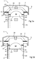
- FIG. 1a shows a cross sectional view of a first example of a valve device 1 in a closed state.
- the valve device 1 comprises a housing 3 connected to a pipe 5.
- the housing forms a chamber 7.
- the chamber 7 comprises a check valve 9 accommodated within the interior of said chamber 7.
- the valve device 1 further comprises a float valve 11 situated in the pipe 5.
- the float valve 11 comprises a movable valve member 13 and a float valve seat 15.
- the pipe 5 has in the illustrated example a uniformly straight cylindrical shape.
- the pipe 5 is adapted to be able to be connected to a piping system (not shown) containing some sort of liquid, preferably waste water.
- the waste water of the piping system is generated from sources separated from the valve device 1.
- the valve device 1 is arranged on the piping system to let in ambient fluids such as air to achieve pressure equalization.
- Piping systems generally are subjected to fluctuations in pressure and volume of the fluid, in this case a liquid in the form of waste water, which it is arranged to accommodate.
- both the check valve 9 and the float valve 11 are in a closed state.
- the check valve 9 is closed towards a check valve seat 17.
- the float valve 11 is closed towards the float valve seat 15. This prevents fluid communication between the piping system and the atmosphere surrounding the outside of the chamber 3 of the valve device 1.
- the float valve 11 is arranged to close when a liquid from the piping system to which it is connected rises up in the pipe 5 of the valve device 1. This further prevents fluid communication between the chamber and the pipe 5. This has the effect that waste water is prevented to reach the chamber 7 of the valve device 1. This helps to keep the chamber 7 and the individual parts of the check valve 9 from being contaminated by the waste water from the piping system. Such contamination could potentially affect the functionality of the check valve, and in worst case lead to a non-complete seal of said valve 9 which could lead to leakage from the check valve 9 into the surrounding atmosphere.
- the check valve 9 is arranged to be in the closed state when a pressure difference between the pressure in the surrounding atmosphere and the pressure within the chamber is below a predetermined value.
- the only forces acting on the check valve 9 are the differences in said pressures and the weight of the check valve 9, affected by gravity.
- the check valve 9 is closed when pressure within the chamber 7 is close to equal or higher than the pressure of the atmosphere surrounding the outside of the valve device 1.
- the check valve 9 seals an opening through which fluid communication is established between said within and outside the chamber 7.
- a difference in pressure between inside the chamber 7 and the surrounding atmosphere can occur, either by the pressure within the chamber 7 or any system connected thereto dropping or by the pressure of the surrounding atmosphere increasing. If such a difference in pressure reaches the pre-determined value, said check valve will open.
- the predetermined value is set such that the check valve opens when a force overcoming the weight of the check valve 9 is exceeded.
- the check valve 9 will then open to equalize the pressure difference by allowing a flow of air to enter the chamber 7 from the surrounding atmosphere.
- This required force can be varied by use of springs and/or weights.
- the springs can for example be arranged to either lower or increasing the required force, and consequently the pre-determined value, depending on the placement of said springs in relation to the movable parts of the check valve 9.
- a spring placed between a supporting structure 19 of the check valve and an interior top surface 21 of the chamber 7 would act against the opening of the check valve 9 and hence increase the pre-determined value required to open the check valve 9.
- the check valve 9 prevents equalization in pressure if the pressure is higher inside the chamber 7 than of the surrounding atmosphere, as a higher pressure within the chamber 7 would only press the check valve 9 further against its valve seat 17.
- Figure 1b shows a cross sectional view of said first example of a valve device 1 in an open state.
- the check valve 9 is arranged to allow fluid communication from the surrounding atmosphere to the chamber 7 in the open state.
- the check valve 9 is normally in the closed state and switches to the open state when the pressure difference between the pressure in the surrounding atmosphere and the pressure within the chamber 7 is equal to or higher than the predetermined value.
- figure 1a and 1b The only difference between figure 1a and 1b is that the state of the valve device 1, in that both the check valve 9 and the float valve 11 in figure 1b are open for fluid communication.
- the check valve 9 being open means that fluid communication is open between the surrounding atmosphere and the inside of the chamber 7, and as the float valve 11 also is open fluid communication is hence allowed throughout the valve device 1 so that a flow of air is able to flow from the outside surrounding atmosphere, through the valve device 1 and into the connected piping system.
- pressure equalization is initiated.
- Such pressure equalization can be needed in a piping system due to various reasons.
- a waste water piping system which system comprises at least one waste water generator, such as a toilet or a sink
- pressure equalization may be needed to avoid emptying the water traps arranged in the waste water generators. If the water traps of a waste water piping system are emptied, foul odours can reach the interior of a house or building in which the waste water piping system is arranged.
- These types of systems are almost always equipped with said water traps to prevent the gases and odours from the piping system to rise up through the pipes and enter the rooms in which the waste water generators such as toilets or sinks are provided.
- the flow of said waste water can cause a negative pressure change within the pipe, which in turn can cause a suction effect.
- the suction effect may drain the water from any water trap into the waste water piping. If the waste water trap is empty the barrier it is arranged to create is removed which leads to waste gases and odours to be able to escape the piping system and enter the room in which the waste water generator is located.
- the valve device 1 disclosed herein eliminates this problem as the negative pressure change within the piping system is equalized by means of the opening of the check valve 9 arranged in the valve device 1. As described above, the open check valve 9 lets fluid such as air from the surrounding atmosphere into the interior of the waste water piping system.
- the float valve 11 according to embodiments disclosed in relation to figure 1a and 1b comprises a movable valve member 13 and a float valve seat 15.
- the valve seat 15 is situated on an interior wall surface 25 of the pipe.
- the movable valve member 13 further comprises a substantially convex top surface 27 and a flat bottom surface 23 corresponding to an area defined by the perimeter of a lowest portion 29 of the convex top surface 27.
- the convex top surface 27 has the shape of a section of a sphere.
- the sphere has been cut in a plane going through the centre of said sphere. This in turn means that an angle ⁇ between a tangential plane 31 parallel to the lowest portion 29 of the convex top surface 27 and the flat bottom surface 23 is a right angle ⁇ '.
- the flow of air passing the movable valve member 13 is guided such that when the air passes the edge of the flat bottom surface 23, turbulence in the air flow, as for example would occur with float valves 11 comprising round movable valve members 13, is alleviated. Turbulence in the air flow can cause vibrations of the movable valve member 13. This may be the cause of unwanted sounds. This may also be the cause of a decreased air flow around the movable valve member 13.
- the movable valve member 13 according to the disclosure therefore provides a valve device 1 with an improved air flow and with less turbulence and accompanied noise, which can be a nuisance for people using waste water generators associated with the piping system.
- the illustrated shape of the substantially convex top surface 27 is just an example.
- the convex top surface 27 may have any shape as long as it is convex.
- the convex top surface 27 may have the shape of a section of an oblate spheroid.
- the angle ⁇ between the tangential plane 31, parallel to the lowest portion 29 of the convex top surface 27 and the flat bottom surface 23 of the movable valve member 13 may have a sharp angle ⁇ ".
- FIG 2a shows a cross sectional view of a second example of a valve device 1 in a closed state.
- the valve device 1 comprises a housing 3 connected to a pipe 5.
- the housing 3 forms a chamber 7.
- the chamber 7 comprises a check valve 9 accommodated within the interior of said chamber 7 and a float valve 11 situated in the pipe 5, wherein the float valve 11 comprises a movable valve member 13 and a float valve seat 15.
- the pipe 5 is adapted to be able to be connected to a piping system containing some sort of liquid, preferably waste water. The waste water of the piping system is generated from sources separated from the valve device.
- the valve device 1 is arranged on the piping system to let in ambient fluids such as air to obtain pressure equalization.
- Piping systems generally are subjected to fluctuations in pressure and volume of the fluid, in this case a liquid in the form of waste water, which it is arranged to accommodate.
- the pipe 5 comprises a flared portion 33, flaring out in a direction towards a lower end 35 of the pipe 5.
- the flared portion 33 is in the shape of a truncated cone.
- other flared shapes are also possible, such as a rounded flared shape or other, without deviating from the scope of the disclosure.
- the convex top surface 27 of the illustrated movable valve member 13, depicted in figure 2a has the shape of a section of a sphere.
- the sphere is cut by a plane above the centre of the sphere.
- the illustrated shape of the substantially convex surface 27 is just an example.
- the convex top surface 27 may have any shape as long as it is convex.
- the convex top surface may have the shape of a section of an oblate spheroid.
- the angle ⁇ between the tangential plane 31, parallel to the lowest portion 29 of the convex top surface 27 and the flat bottom surface 23 of the movable valve member 13 may have a right angle ⁇ '.
- Figure 2b depicts the same valve device as figure 2a but in an open state in regards to the check valve 9 and the float valve 11.
- the open space between the movable valve member 13 and the interior wall surface 25 of the pipe 5 is larger than for the example depicted in 1b.
- the speed of air being lower further lowers the risk of turbulence which can cause the movable valve member to wobble or vibrate which was described with reference to figure 1a and 1b .
- the substantially convex top surface 27 of the movable valve member 13 of the float valve 11 can be designed in different ways,.
- the flat bottom surface 23 is in these illustrated examples the area defined by the perimeter of the lowest portion 29 of the convex top surface 27.
- the shape of the movable valve member 13 can be modified to further comprise an intermediate substantially cylindrical section 37, the cylindrical section 37 extending between the perimeter of the lowest portion 29 of the convex top surface 27 and the flat bottom surface 23.
- the various shapes of the movable valve member 13 possible will be described in more detail with reference to figures 3a-3h .
- the various shapes and designs of the movable valve member 13 can change the characteristics of the air flow and the overall features of the valve device 1, which various characteristics may be of equal importance depending on the type of piping system the valve device 1 is connected to. Space available for installation in said systems may also affect the demands on the valve, which can affect the choice of design for the valve device 1 and its components. For example, if a valve device 1 is to be installed in a very restricted space, a movable valve member 13 which is as flat/thin as possible might be required for the valve device 1 to fit. As a contrary example, if space is a non-issue, the valve device 1 may be designed to achieve the best possible flow with the lowest amount of turbulence as the design parameters are more lenient in this case.
- An intermediate cylindrical section 37 situated between the convex top surface 27 and the flat bottom surface 23 further increases the stability of the movable valve member 13 as the passage wherein the air flow is guided to a more stable or efficient air flow is increased.
- a more stable movable valve member 13 is also desirable as it leads to less turbulence and lesser risk that the movable valve member tilts or tips or even gets stuck. This would negatively affect the sealing function of the float valve so that it does not seal properly which may affect the flow within the valve device 1 in a negative way.
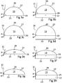
- Figure 3a-3h shows side views of different variations of the shape of a movable valve member 13 of the float valve 11 according to different examples. These various examples are variations of certain preferred features of the invention, and combinations thereof.
- the shape of the convex top surface 27 can be any convex shape, but preferably a section of a sphere or the shape of an oblate spheroid, are used. Said shapes can thereafter be coupled to, directly or in-directly, with the flat bottom surface 23. In the case of a sphere, the flat bottom surface 23 can be seen as a plane cutting the sphere, either through the centre of the sphere, or between the centre and an upper edge 39.
- the plane going through said spheroid can in a corresponding way go through its centre or above said centre.
- Both above described shapes of the movable valve member 13 may also comprise an intermediate substantially cylindrical section 37.
- the cylindrical section 37 extends between the perimeter of the lowest portion 29 of the convex top surface 27 and the flat bottom surface 23. Such an intermediate section 37 is, as described earlier, advantageous from a perspective regarding air flow within the valve device 1.
- Figure 3a shows a sphere with the flat bottom surface 23 going through above the centre of said sphere. Further, in the illustrated example of figure 3a , a tangential plane 31 parallel to the lowest portion 29 of the convex top surface 27 and the flat bottom surface forms a sharp angle ⁇ ".
- Figure 3b shows a shape similar to that of figure 3a , but further comprising an intermediate cylindrical section 37.
- Figure 3c shows a sphere with the flat bottom surface 23 going through the centre of said sphere. Further, in the illustrated example of Fig 3c , a tangential plane 31 parallel to the lowest portion 29 of the convex top surface 27 and the flat bottom surface forms a right angle ⁇ '.
- Figure 3d shows a shape similar to that of figure 3c , but further comprising an intermediate cylindrical section 37.
- Figure 3e shows an oblate spheroid with the flat bottom surface 23 going through above the centre of said oblate spheroid. Further, in the illustrated example of figure 3e , a tangential plane 31 parallel to the lowest portion 29 of the convex top surface 27 and the flat bottom surface forms a sharp angle ⁇ ".
- Figure 3f shows a shape similar to that of figure 3e , but further comprising an intermediate cylindrical section 37.
- Figure 3g shows an oblate spheroid with the flat bottom surface 23 going through the centre of said oblate spheroid. Further, in the illustrated example of figure 3g , a tangential plane 31 parallel to the lowest portion 29 of the convex top surface 27 and the flat bottom surface forms a right angle ⁇ '.
- Figure 3h shows a shape similar to that of figure 3g , but further comprising an intermediate cylindrical section 37.
- FIG 4a shows a schematically side view of an example of a cage 41 comprising a float valve 11 in an open state.
- the float valve 11 is arranged within a cage 41, or a cage-like structure.
- the float valve 11 may therefore be assembled within said cage 41 outside the valve device 1. This can aid in making manufacturing of the device 1 as a whole easier. It can also make maintenance more lenient to perform as the device 1 may be adapted to remove the cage 41 without disrupting the check valve 9 or other sensitive parts.
- the float valve 11 according to the examples of figures 4a and 4b has the float valve seat 15 arranged in the cage 41, at an upper section 43 of the cage 41.
- valve seat arranged in a cage 41 can make an installation and/or maintenance procedure much easier as the cage 41 can be removed and worked on outside the otherwise hard to reach inside of the pipe 5 of the valve device 1.
- Figure 4b shows a schematically side view of the cage 41 in figure 4a comprising a float valve 11 in a closed state.
- This float valve 11 and the cage 41 of figure 4b can be seen as the same example as that of figure 4a , with the only difference being that the float valve 11 is closed in figure 4b .
- the float valve 11 seals against the valve seat 15 arranged at the upper section 43 of the cage 41.
- the movable valve member 13 will not need any other type of support projection within the pipe 5 to not fall down into a connecting piping system, as a lower section 45 of the cage 41 can act as a stop for the movable valve member 13 when it is not subjected to any liquid from said piping system.
- FIG. 5 shows a schematically cross sectional view of an example of a cage 41 comprising an open float valve 11 arranged in a pipe 5.
- This example can be seen as the same example as in figure 4a and 4b , wherein the cage 41 has been arranged within a pipe 5, which pipe 5 is a pipe 5 of the valve device 1 according to the invention.
- the cage 41 is fastened to the interior wall surface 25 of the pipe 5 by means of any type of fastening means according to known technology.
- said valve seat 15 may be changed in height placement within the pipe 5 if so desired, compared to having a fixed valve seat 15 within a pipe 5 of a valve device 1.
- Figure 6 shows a cross sectional view of an alternative example of a valve device 1 according to the present invention.
- the valve device 1 of figure 6 has a check valve 9 being subjected to the pressure differences between the interior of the chamber 7 and the surrounding atmosphere as well as the gravity affecting the mass of the check valve itself 9, as in previously described examples.
- the movable valve member 13 of this example is a sphere with the flat bottom surface 23 going through the centre of said sphere, further comprising an intermediate cylindrical section 37.
- the valve device 1 according to the scope of the claims and the description may be altered in various ways to be adapted to different scenarios and environments, with figure 6 merely depicting one example of said variations.
- Figure 7 shows a schematically view of a piping system 47 with three height levels and comprising a plurality of water inlets 49.
- the piping system 47 depicted herein illustrates how a piping system 47, such as a waste water piping system 47 can be installed in different floors 51 of a building or facility.
- Individual inlets 49 are connected to pipe sections 53 arranged within each separate floor 51 of the building or facility, and the separate pipe sections 53 are then connected to a common waste pipeline 55.
- the common pipeline 55 then leads all accumulated waste water to a sewer and/or a waste management system.
- FIG 8a shows a schematically cross sectional view of a waste water piping system 47 with a plurality of waste water generators 57 and comprising a valve device 1.
- the waste water piping system can comprise a plurality of valve devices 1.
- the valve device 1 in this example is connected to a pipe 59 which is arranged within a bathroom situated on a floor 51 of a building.
- each waste water generator 57 is provided with a water trap 61 which leads to the piping system 47 not being in direct contact with the air within the rooms of the building.
- a float valve of the valve device is arranged to close when a liquid from the piping system to which it is connected rises up in the pipe of the valve device 1. This further prevents fluid communication between a chamber of the valve device and the pipe. This has the effect that waste water is prevented to reach the chamber of the valve device. This helps to keep the chamber and the individual parts of the valve device from being contaminated by the waste water from the piping system. Such contamination could potentially affect the functionality of the valve device, and in worst case lead to a non-complete seal of said valve device, which could lead to leakage from the valve device 1 into the surrounding atmosphere.
- the valve device 1 is located at a level below all the waste water generators 57 at a same floor 51 of a building. In one example, the valve device 1 is located at a level below nearby waste water generators 57 such as waste water generators 57 in the same room as the valve device 1. In an environment where the valve device 1 is at a low level in relation to the waste water generators 57 the risk is increased that a liquid from the piping system 47 to which the valve device 1 is connected rises up in the pipe of the valve device 1. In this environment with an increased risk that liquid raises from the piping system 47, the incorporation of the herein described float valve in the valve device 1 is even more beneficial.
- Figure 8b shows a schematically cross sectional view of a waste water piping system 47 with a plurality of waste water generators 57 and comprising a valve device 1.
- the valve device 1 in this example is connected to a pipe 59 which is arranged under the floor under a bathroom situated on the floor 51 of a building.
- the functionally of the piping system 47 of this example is the same as the functionality of the piping system 47 described with reference to figure 8a , with the exception of the valve device 1 being arranged under the floor of the bathroom instead of directly within the interior of said bathroom.
- This in an alternative placement which works as well, as long as the pressure of internal structure of the floor exhibits substantially the same pressure as inside the rooms of the building.
Landscapes
- Engineering & Computer Science (AREA)
- Structural Engineering (AREA)
- Life Sciences & Earth Sciences (AREA)
- Hydrology & Water Resources (AREA)
- Public Health (AREA)
- Water Supply & Treatment (AREA)
- Health & Medical Sciences (AREA)
- General Engineering & Computer Science (AREA)
- Environmental & Geological Engineering (AREA)
- Mechanical Engineering (AREA)
- Self-Closing Valves And Venting Or Aerating Valves (AREA)
- Float Valves (AREA)
- Sink And Installation For Waste Water (AREA)
Applications Claiming Priority (2)
| Application Number | Priority Date | Filing Date | Title |
|---|---|---|---|
| SE1551364A SE539278C2 (en) | 2015-10-21 | 2015-10-21 | Valve device |
| PCT/SE2016/051006 WO2017069685A1 (en) | 2015-10-21 | 2016-10-18 | Valve device |
Publications (3)
| Publication Number | Publication Date |
|---|---|
| EP3365503A1 EP3365503A1 (en) | 2018-08-29 |
| EP3365503A4 EP3365503A4 (en) | 2019-07-03 |
| EP3365503B1 true EP3365503B1 (en) | 2021-03-24 |
Family
ID=58629585
Family Applications (1)
| Application Number | Title | Priority Date | Filing Date |
|---|---|---|---|
| EP16857883.9A Active EP3365503B1 (en) | 2015-10-21 | 2016-10-18 | Valve device |
Country Status (5)
| Country | Link |
|---|---|
| EP (1) | EP3365503B1 (enExample) |
| JP (1) | JP7039466B2 (enExample) |
| SE (1) | SE539278C2 (enExample) |
| TW (1) | TWI751117B (enExample) |
| WO (1) | WO2017069685A1 (enExample) |
Families Citing this family (4)
| Publication number | Priority date | Publication date | Assignee | Title |
|---|---|---|---|---|
| TWI635232B (zh) * | 2017-09-19 | 2018-09-11 | 生特興業有限公司 | Pressure balance valve |
| CN108252394B (zh) * | 2018-01-10 | 2019-12-10 | 河海大学 | 一种用于深层调蓄隧道排气的驼峰型通气系统 |
| JP2020023997A (ja) * | 2018-08-07 | 2020-02-13 | 丸一株式会社 | 吸気弁 |
| CN115126044A (zh) * | 2022-07-30 | 2022-09-30 | 无锡汇田水务科技有限公司 | 一种浮球自找正密封的负压抑制装置和密闭储水容器 |
Family Cites Families (16)
| Publication number | Priority date | Publication date | Assignee | Title |
|---|---|---|---|---|
| GB405385A (en) * | 1932-09-17 | 1934-02-08 | Glenfield & Kennedy Ltd | Improvements in air release and ventilating valves for water mains and the like |
| GB1274843A (en) * | 1968-05-14 | 1972-05-17 | Glenfield & Kennedy Ltd | Improvements in air release and ventilating valves |
| DE7636915U1 (de) * | 1976-11-24 | 1977-08-18 | Bosch-Siemens Hausgeraete Gmbh, 7000 Stuttgart | Rueckschlagventil fuer wasserfuehrende geraete, insbesondere geschirrspuel- oder waschmaschinen |
| JPH05332203A (ja) * | 1992-06-02 | 1993-12-14 | Fuji Oozx Inc | 内燃機関用排気ガス還流制御弁装置 |
| JPH08284227A (ja) * | 1995-04-18 | 1996-10-29 | Kubota Corp | 排水配管の集合管 |
| JP2001271952A (ja) | 2000-03-24 | 2001-10-05 | Shin Meiwa Ind Co Ltd | 排気用バルブ |
| JP2004124356A (ja) | 2001-09-06 | 2004-04-22 | Morinaga Eng Kk | 排水管システム及び排水用通気弁装置 |
| JP2004019131A (ja) * | 2002-06-12 | 2004-01-22 | Kubota Corp | 排気弁及び排水管システム |
| EP2224066A1 (en) * | 2009-02-25 | 2010-09-01 | Studor S.A. | Air admittance valve |
| JP5199182B2 (ja) | 2009-05-26 | 2013-05-15 | 栗本商事株式会社 | 逆止弁およびこれに使用される逆止弁用弁体 |
| JP2012013097A (ja) * | 2010-06-29 | 2012-01-19 | Maezawa Kasei Ind Co Ltd | 吸気弁 |
| JP5649128B2 (ja) | 2011-07-11 | 2015-01-07 | 千代田工業株式会社 | 水道用空気弁及びそれを備えた消火栓 |
| CN104471157B (zh) * | 2012-05-28 | 2017-03-29 | 麦卡尔平有限公司 | 用于污水管道的阀装置 |
| JP5971853B2 (ja) | 2012-10-05 | 2016-08-17 | 前澤化成工業株式会社 | 吸気弁装置 |
| US9200718B2 (en) | 2013-01-29 | 2015-12-01 | Mueller International, Llc | Air valve seat |
| KR200478332Y1 (ko) * | 2015-02-25 | 2015-09-18 | 주식회사 에스엠지 | 양흡입 에어 벤트 밸브 |
-
2015
- 2015-10-21 SE SE1551364A patent/SE539278C2/en unknown
-
2016
- 2016-10-18 EP EP16857883.9A patent/EP3365503B1/en active Active
- 2016-10-18 WO PCT/SE2016/051006 patent/WO2017069685A1/en not_active Ceased
- 2016-10-18 JP JP2018521273A patent/JP7039466B2/ja active Active
- 2016-10-20 TW TW105133868A patent/TWI751117B/zh active
Non-Patent Citations (1)
| Title |
|---|
| None * |
Also Published As
| Publication number | Publication date |
|---|---|
| SE539278C2 (en) | 2017-06-13 |
| SE1551364A1 (en) | 2017-04-22 |
| JP2018532916A (ja) | 2018-11-08 |
| EP3365503A4 (en) | 2019-07-03 |
| TW201720996A (zh) | 2017-06-16 |
| TWI751117B (zh) | 2022-01-01 |
| WO2017069685A1 (en) | 2017-04-27 |
| JP7039466B2 (ja) | 2022-03-22 |
| EP3365503A1 (en) | 2018-08-29 |
Similar Documents
| Publication | Publication Date | Title |
|---|---|---|
| EP3365503B1 (en) | Valve device | |
| CA2378909C (en) | Ventilation apparatus | |
| CN105386507B (zh) | 浮力式自动密封防臭地漏 | |
| KR101264017B1 (ko) | 악취 및 역류 방지 기능을 갖는 배수구 개폐 조절 장치 | |
| KR102356646B1 (ko) | 건축물의 오배수관용 통기밸브 | |
| AU2008217536C1 (en) | Sewer overflow relief device | |
| JP5101963B2 (ja) | 通気弁機構付き継手 | |
| KR20100033034A (ko) | 욕실의 배수시스템 | |
| JPH0853910A (ja) | 床排水用のトラップ | |
| KR20230001827U (ko) | 이중봉수구조를 가지는 배수트랩 | |
| EP2241686B1 (en) | High capacity air admittance valve for sanitary waste pipe system | |
| KR101273417B1 (ko) | 아파트 베란다를 관통하는 역류 방지형 하수관 | |
| JP2003286735A (ja) | 浴室ユニットの排水トラップ | |
| JP2007225146A (ja) | 排水トラップおよび排水装置 | |
| JP2003119859A (ja) | 排水システムと排水マス | |
| JP2017203359A (ja) | 排水装置 | |
| JP7278556B2 (ja) | 排水装置 | |
| JP7040879B2 (ja) | 廃水配管システムおよび空気弁 | |
| JP2004124356A (ja) | 排水管システム及び排水用通気弁装置 | |
| KR102698368B1 (ko) | 배수트랩 | |
| KR102835233B1 (ko) | 오/배수와 공기통기 통합용 체크밸브 및 이를 이용한 듀얼시스템 | |
| JP7544500B2 (ja) | 通気弁 | |
| JP2014119111A (ja) | 排水用低位通気弁 | |
| CN108018937A (zh) | 漂浮式地漏 | |
| KR20230001982U (ko) | 건축물의 오배수관용 와류형 통기밸브 |
Legal Events
| Date | Code | Title | Description |
|---|---|---|---|
| STAA | Information on the status of an ep patent application or granted ep patent |
Free format text: STATUS: THE INTERNATIONAL PUBLICATION HAS BEEN MADE |
|
| PUAI | Public reference made under article 153(3) epc to a published international application that has entered the european phase |
Free format text: ORIGINAL CODE: 0009012 |
|
| STAA | Information on the status of an ep patent application or granted ep patent |
Free format text: STATUS: REQUEST FOR EXAMINATION WAS MADE |
|
| 17P | Request for examination filed |
Effective date: 20180316 |
|
| AK | Designated contracting states |
Kind code of ref document: A1 Designated state(s): AL AT BE BG CH CY CZ DE DK EE ES FI FR GB GR HR HU IE IS IT LI LT LU LV MC MK MT NL NO PL PT RO RS SE SI SK SM TR |
|
| AX | Request for extension of the european patent |
Extension state: BA ME |
|
| DAV | Request for validation of the european patent (deleted) | ||
| DAX | Request for extension of the european patent (deleted) | ||
| A4 | Supplementary search report drawn up and despatched |
Effective date: 20190531 |
|
| RIC1 | Information provided on ipc code assigned before grant |
Ipc: F16K 24/06 20060101ALI20190524BHEP Ipc: F16K 33/00 20060101ALI20190524BHEP Ipc: E03C 1/00 20060101AFI20190524BHEP Ipc: E03F 5/08 20060101ALI20190524BHEP |
|
| GRAP | Despatch of communication of intention to grant a patent |
Free format text: ORIGINAL CODE: EPIDOSNIGR1 |
|
| STAA | Information on the status of an ep patent application or granted ep patent |
Free format text: STATUS: GRANT OF PATENT IS INTENDED |
|
| INTG | Intention to grant announced |
Effective date: 20200515 |
|
| GRAS | Grant fee paid |
Free format text: ORIGINAL CODE: EPIDOSNIGR3 |
|
| GRAJ | Information related to disapproval of communication of intention to grant by the applicant or resumption of examination proceedings by the epo deleted |
Free format text: ORIGINAL CODE: EPIDOSDIGR1 |
|
| GRAL | Information related to payment of fee for publishing/printing deleted |
Free format text: ORIGINAL CODE: EPIDOSDIGR3 |
|
| STAA | Information on the status of an ep patent application or granted ep patent |
Free format text: STATUS: REQUEST FOR EXAMINATION WAS MADE |
|
| GRAP | Despatch of communication of intention to grant a patent |
Free format text: ORIGINAL CODE: EPIDOSNIGR1 |
|
| INTC | Intention to grant announced (deleted) | ||
| STAA | Information on the status of an ep patent application or granted ep patent |
Free format text: STATUS: GRANT OF PATENT IS INTENDED |
|
| INTG | Intention to grant announced |
Effective date: 20201015 |
|
| GRAA | (expected) grant |
Free format text: ORIGINAL CODE: 0009210 |
|
| STAA | Information on the status of an ep patent application or granted ep patent |
Free format text: STATUS: THE PATENT HAS BEEN GRANTED |
|
| AK | Designated contracting states |
Kind code of ref document: B1 Designated state(s): AL AT BE BG CH CY CZ DE DK EE ES FI FR GB GR HR HU IE IS IT LI LT LU LV MC MK MT NL NO PL PT RO RS SE SI SK SM TR |
|
| REG | Reference to a national code |
Ref country code: GB Ref legal event code: FG4D |
|
| REG | Reference to a national code |
Ref country code: CH Ref legal event code: EP |
|
| REG | Reference to a national code |
Ref country code: IE Ref legal event code: FG4D |
|
| REG | Reference to a national code |
Ref country code: AT Ref legal event code: REF Ref document number: 1374645 Country of ref document: AT Kind code of ref document: T Effective date: 20210415 Ref country code: DE Ref legal event code: R096 Ref document number: 602016055001 Country of ref document: DE |
|
| REG | Reference to a national code |
Ref country code: SE Ref legal event code: TRGR |
|
| REG | Reference to a national code |
Ref country code: LT Ref legal event code: MG9D |
|
| PG25 | Lapsed in a contracting state [announced via postgrant information from national office to epo] |
Ref country code: HR Free format text: LAPSE BECAUSE OF FAILURE TO SUBMIT A TRANSLATION OF THE DESCRIPTION OR TO PAY THE FEE WITHIN THE PRESCRIBED TIME-LIMIT Effective date: 20210324 Ref country code: FI Free format text: LAPSE BECAUSE OF FAILURE TO SUBMIT A TRANSLATION OF THE DESCRIPTION OR TO PAY THE FEE WITHIN THE PRESCRIBED TIME-LIMIT Effective date: 20210324 Ref country code: GR Free format text: LAPSE BECAUSE OF FAILURE TO SUBMIT A TRANSLATION OF THE DESCRIPTION OR TO PAY THE FEE WITHIN THE PRESCRIBED TIME-LIMIT Effective date: 20210625 Ref country code: NO Free format text: LAPSE BECAUSE OF FAILURE TO SUBMIT A TRANSLATION OF THE DESCRIPTION OR TO PAY THE FEE WITHIN THE PRESCRIBED TIME-LIMIT Effective date: 20210624 Ref country code: BG Free format text: LAPSE BECAUSE OF FAILURE TO SUBMIT A TRANSLATION OF THE DESCRIPTION OR TO PAY THE FEE WITHIN THE PRESCRIBED TIME-LIMIT Effective date: 20210624 |
|
| PG25 | Lapsed in a contracting state [announced via postgrant information from national office to epo] |
Ref country code: RS Free format text: LAPSE BECAUSE OF FAILURE TO SUBMIT A TRANSLATION OF THE DESCRIPTION OR TO PAY THE FEE WITHIN THE PRESCRIBED TIME-LIMIT Effective date: 20210324 Ref country code: LV Free format text: LAPSE BECAUSE OF FAILURE TO SUBMIT A TRANSLATION OF THE DESCRIPTION OR TO PAY THE FEE WITHIN THE PRESCRIBED TIME-LIMIT Effective date: 20210324 |
|
| REG | Reference to a national code |
Ref country code: NL Ref legal event code: MP Effective date: 20210324 |
|
| REG | Reference to a national code |
Ref country code: AT Ref legal event code: MK05 Ref document number: 1374645 Country of ref document: AT Kind code of ref document: T Effective date: 20210324 |
|
| PG25 | Lapsed in a contracting state [announced via postgrant information from national office to epo] |
Ref country code: NL Free format text: LAPSE BECAUSE OF FAILURE TO SUBMIT A TRANSLATION OF THE DESCRIPTION OR TO PAY THE FEE WITHIN THE PRESCRIBED TIME-LIMIT Effective date: 20210324 |
|
| PG25 | Lapsed in a contracting state [announced via postgrant information from national office to epo] |
Ref country code: CZ Free format text: LAPSE BECAUSE OF FAILURE TO SUBMIT A TRANSLATION OF THE DESCRIPTION OR TO PAY THE FEE WITHIN THE PRESCRIBED TIME-LIMIT Effective date: 20210324 Ref country code: EE Free format text: LAPSE BECAUSE OF FAILURE TO SUBMIT A TRANSLATION OF THE DESCRIPTION OR TO PAY THE FEE WITHIN THE PRESCRIBED TIME-LIMIT Effective date: 20210324 Ref country code: LT Free format text: LAPSE BECAUSE OF FAILURE TO SUBMIT A TRANSLATION OF THE DESCRIPTION OR TO PAY THE FEE WITHIN THE PRESCRIBED TIME-LIMIT Effective date: 20210324 Ref country code: AT Free format text: LAPSE BECAUSE OF FAILURE TO SUBMIT A TRANSLATION OF THE DESCRIPTION OR TO PAY THE FEE WITHIN THE PRESCRIBED TIME-LIMIT Effective date: 20210324 Ref country code: SM Free format text: LAPSE BECAUSE OF FAILURE TO SUBMIT A TRANSLATION OF THE DESCRIPTION OR TO PAY THE FEE WITHIN THE PRESCRIBED TIME-LIMIT Effective date: 20210324 |
|
| PG25 | Lapsed in a contracting state [announced via postgrant information from national office to epo] |
Ref country code: IS Free format text: LAPSE BECAUSE OF FAILURE TO SUBMIT A TRANSLATION OF THE DESCRIPTION OR TO PAY THE FEE WITHIN THE PRESCRIBED TIME-LIMIT Effective date: 20210724 Ref country code: PT Free format text: LAPSE BECAUSE OF FAILURE TO SUBMIT A TRANSLATION OF THE DESCRIPTION OR TO PAY THE FEE WITHIN THE PRESCRIBED TIME-LIMIT Effective date: 20210726 Ref country code: PL Free format text: LAPSE BECAUSE OF FAILURE TO SUBMIT A TRANSLATION OF THE DESCRIPTION OR TO PAY THE FEE WITHIN THE PRESCRIBED TIME-LIMIT Effective date: 20210324 Ref country code: RO Free format text: LAPSE BECAUSE OF FAILURE TO SUBMIT A TRANSLATION OF THE DESCRIPTION OR TO PAY THE FEE WITHIN THE PRESCRIBED TIME-LIMIT Effective date: 20210324 Ref country code: SK Free format text: LAPSE BECAUSE OF FAILURE TO SUBMIT A TRANSLATION OF THE DESCRIPTION OR TO PAY THE FEE WITHIN THE PRESCRIBED TIME-LIMIT Effective date: 20210324 |
|
| REG | Reference to a national code |
Ref country code: DE Ref legal event code: R097 Ref document number: 602016055001 Country of ref document: DE |
|
| PG25 | Lapsed in a contracting state [announced via postgrant information from national office to epo] |
Ref country code: DK Free format text: LAPSE BECAUSE OF FAILURE TO SUBMIT A TRANSLATION OF THE DESCRIPTION OR TO PAY THE FEE WITHIN THE PRESCRIBED TIME-LIMIT Effective date: 20210324 Ref country code: AL Free format text: LAPSE BECAUSE OF FAILURE TO SUBMIT A TRANSLATION OF THE DESCRIPTION OR TO PAY THE FEE WITHIN THE PRESCRIBED TIME-LIMIT Effective date: 20210324 Ref country code: ES Free format text: LAPSE BECAUSE OF FAILURE TO SUBMIT A TRANSLATION OF THE DESCRIPTION OR TO PAY THE FEE WITHIN THE PRESCRIBED TIME-LIMIT Effective date: 20210324 |
|
| PLBE | No opposition filed within time limit |
Free format text: ORIGINAL CODE: 0009261 |
|
| STAA | Information on the status of an ep patent application or granted ep patent |
Free format text: STATUS: NO OPPOSITION FILED WITHIN TIME LIMIT |
|
| PG25 | Lapsed in a contracting state [announced via postgrant information from national office to epo] |
Ref country code: SI Free format text: LAPSE BECAUSE OF FAILURE TO SUBMIT A TRANSLATION OF THE DESCRIPTION OR TO PAY THE FEE WITHIN THE PRESCRIBED TIME-LIMIT Effective date: 20210324 |
|
| 26N | No opposition filed |
Effective date: 20220104 |
|
| REG | Reference to a national code |
Ref country code: CH Ref legal event code: PL |
|
| PG25 | Lapsed in a contracting state [announced via postgrant information from national office to epo] |
Ref country code: IS Free format text: LAPSE BECAUSE OF FAILURE TO SUBMIT A TRANSLATION OF THE DESCRIPTION OR TO PAY THE FEE WITHIN THE PRESCRIBED TIME-LIMIT Effective date: 20210724 |
|
| REG | Reference to a national code |
Ref country code: BE Ref legal event code: MM Effective date: 20211031 |
|
| PG25 | Lapsed in a contracting state [announced via postgrant information from national office to epo] |
Ref country code: MC Free format text: LAPSE BECAUSE OF FAILURE TO SUBMIT A TRANSLATION OF THE DESCRIPTION OR TO PAY THE FEE WITHIN THE PRESCRIBED TIME-LIMIT Effective date: 20210324 |
|
| PG25 | Lapsed in a contracting state [announced via postgrant information from national office to epo] |
Ref country code: LU Free format text: LAPSE BECAUSE OF NON-PAYMENT OF DUE FEES Effective date: 20211018 Ref country code: BE Free format text: LAPSE BECAUSE OF NON-PAYMENT OF DUE FEES Effective date: 20211031 |
|
| PG25 | Lapsed in a contracting state [announced via postgrant information from national office to epo] |
Ref country code: LI Free format text: LAPSE BECAUSE OF NON-PAYMENT OF DUE FEES Effective date: 20211031 Ref country code: CH Free format text: LAPSE BECAUSE OF NON-PAYMENT OF DUE FEES Effective date: 20211031 |
|
| PG25 | Lapsed in a contracting state [announced via postgrant information from national office to epo] |
Ref country code: IE Free format text: LAPSE BECAUSE OF NON-PAYMENT OF DUE FEES Effective date: 20211018 |
|
| PG25 | Lapsed in a contracting state [announced via postgrant information from national office to epo] |
Ref country code: IT Free format text: LAPSE BECAUSE OF FAILURE TO SUBMIT A TRANSLATION OF THE DESCRIPTION OR TO PAY THE FEE WITHIN THE PRESCRIBED TIME-LIMIT Effective date: 20210324 |
|
| PG25 | Lapsed in a contracting state [announced via postgrant information from national office to epo] |
Ref country code: HU Free format text: LAPSE BECAUSE OF FAILURE TO SUBMIT A TRANSLATION OF THE DESCRIPTION OR TO PAY THE FEE WITHIN THE PRESCRIBED TIME-LIMIT; INVALID AB INITIO Effective date: 20161018 |
|
| PG25 | Lapsed in a contracting state [announced via postgrant information from national office to epo] |
Ref country code: CY Free format text: LAPSE BECAUSE OF FAILURE TO SUBMIT A TRANSLATION OF THE DESCRIPTION OR TO PAY THE FEE WITHIN THE PRESCRIBED TIME-LIMIT Effective date: 20210324 |
|
| P01 | Opt-out of the competence of the unified patent court (upc) registered |
Effective date: 20230530 |
|
| PG25 | Lapsed in a contracting state [announced via postgrant information from national office to epo] |
Ref country code: MK Free format text: LAPSE BECAUSE OF FAILURE TO SUBMIT A TRANSLATION OF THE DESCRIPTION OR TO PAY THE FEE WITHIN THE PRESCRIBED TIME-LIMIT Effective date: 20210324 |
|
| PG25 | Lapsed in a contracting state [announced via postgrant information from national office to epo] |
Ref country code: MT Free format text: LAPSE BECAUSE OF FAILURE TO SUBMIT A TRANSLATION OF THE DESCRIPTION OR TO PAY THE FEE WITHIN THE PRESCRIBED TIME-LIMIT Effective date: 20210324 |
|
| PGFP | Annual fee paid to national office [announced via postgrant information from national office to epo] |
Ref country code: DE Payment date: 20240917 Year of fee payment: 9 |
|
| PGFP | Annual fee paid to national office [announced via postgrant information from national office to epo] |
Ref country code: GB Payment date: 20250822 Year of fee payment: 10 |
|
| PGFP | Annual fee paid to national office [announced via postgrant information from national office to epo] |
Ref country code: FR Payment date: 20250820 Year of fee payment: 10 |
|
| PGFP | Annual fee paid to national office [announced via postgrant information from national office to epo] |
Ref country code: SE Payment date: 20250821 Year of fee payment: 10 |
|
| PG25 | Lapsed in a contracting state [announced via postgrant information from national office to epo] |
Ref country code: TR Free format text: LAPSE BECAUSE OF FAILURE TO SUBMIT A TRANSLATION OF THE DESCRIPTION OR TO PAY THE FEE WITHIN THE PRESCRIBED TIME-LIMIT Effective date: 20210324 |