EP3363752B1 - Entstapelvorrichtung mit rotierender schalenentlastung - Google Patents
Entstapelvorrichtung mit rotierender schalenentlastung Download PDFInfo
- Publication number
- EP3363752B1 EP3363752B1 EP17156414.9A EP17156414A EP3363752B1 EP 3363752 B1 EP3363752 B1 EP 3363752B1 EP 17156414 A EP17156414 A EP 17156414A EP 3363752 B1 EP3363752 B1 EP 3363752B1
- Authority
- EP
- European Patent Office
- Prior art keywords
- immersing
- protrusions
- stack
- dispensing device
- immersion
- Prior art date
- Legal status (The legal status is an assumption and is not a legal conclusion. Google has not performed a legal analysis and makes no representation as to the accuracy of the status listed.)
- Active
Links
Images


Classifications
-
- B—PERFORMING OPERATIONS; TRANSPORTING
- B65—CONVEYING; PACKING; STORING; HANDLING THIN OR FILAMENTARY MATERIAL
- B65G—TRANSPORT OR STORAGE DEVICES, e.g. CONVEYORS FOR LOADING OR TIPPING, SHOP CONVEYOR SYSTEMS OR PNEUMATIC TUBE CONVEYORS
- B65G59/00—De-stacking of articles
- B65G59/06—De-stacking from the bottom of the stack
- B65G59/061—De-stacking from the bottom of the stack articles being separated substantially along the axis of the stack
- B65G59/062—De-stacking from the bottom of the stack articles being separated substantially along the axis of the stack by means of reciprocating or oscillating escapement-like mechanisms
- B65G59/063—De-stacking from the bottom of the stack articles being separated substantially along the axis of the stack by means of reciprocating or oscillating escapement-like mechanisms comprising lifting means
-
- B—PERFORMING OPERATIONS; TRANSPORTING
- B65—CONVEYING; PACKING; STORING; HANDLING THIN OR FILAMENTARY MATERIAL
- B65G—TRANSPORT OR STORAGE DEVICES, e.g. CONVEYORS FOR LOADING OR TIPPING, SHOP CONVEYOR SYSTEMS OR PNEUMATIC TUBE CONVEYORS
- B65G59/00—De-stacking of articles
- B65G59/10—De-stacking nested articles
- B65G59/107—De-stacking nested articles by means of rotary devices or endless elements
- B65G59/108—De-stacking nested articles by means of rotary devices or endless elements the axis of rotation being substantially parallel to the axis of the stack
-
- A—HUMAN NECESSITIES
- A47—FURNITURE; DOMESTIC ARTICLES OR APPLIANCES; COFFEE MILLS; SPICE MILLS; SUCTION CLEANERS IN GENERAL
- A47F—SPECIAL FURNITURE, FITTINGS, OR ACCESSORIES FOR SHOPS, STOREHOUSES, BARS, RESTAURANTS OR THE LIKE; PAYING COUNTERS
- A47F1/00—Racks for dispensing merchandise; Containers for dispensing merchandise
- A47F1/04—Racks or containers with arrangements for dispensing articles, e.g. by means of gravity or springs
- A47F1/08—Racks or containers with arrangements for dispensing articles, e.g. by means of gravity or springs dispensing from bottom
- A47F1/10—Racks or containers with arrangements for dispensing articles, e.g. by means of gravity or springs dispensing from bottom having mechanical dispensing means, e.g. with buttons or handles
- A47F1/106—Racks or containers with arrangements for dispensing articles, e.g. by means of gravity or springs dispensing from bottom having mechanical dispensing means, e.g. with buttons or handles for nested articles, e.g. cups, cones
-
- B—PERFORMING OPERATIONS; TRANSPORTING
- B65—CONVEYING; PACKING; STORING; HANDLING THIN OR FILAMENTARY MATERIAL
- B65B—MACHINES, APPARATUS OR DEVICES FOR, OR METHODS OF, PACKAGING ARTICLES OR MATERIALS; UNPACKING
- B65B43/00—Forming, feeding, opening or setting-up containers or receptacles in association with packaging
- B65B43/42—Feeding or positioning bags, boxes, or cartons in the distended, opened, or set-up state; Feeding preformed rigid containers, e.g. tins, capsules, glass tubes, glasses, to the packaging position; Locating containers or receptacles at the filling position; Supporting containers or receptacles during the filling operation
- B65B43/44—Feeding or positioning bags, boxes, or cartons in the distended, opened, or set-up state; Feeding preformed rigid containers, e.g. tins, capsules, glass tubes, glasses, to the packaging position; Locating containers or receptacles at the filling position; Supporting containers or receptacles during the filling operation from supply magazines
-
- G—PHYSICS
- G07—CHECKING-DEVICES
- G07F—COIN-FREED OR LIKE APPARATUS
- G07F13/00—Coin-freed apparatus for controlling dispensing or fluids, semiliquids or granular material from reservoirs
- G07F13/10—Coin-freed apparatus for controlling dispensing or fluids, semiliquids or granular material from reservoirs with associated dispensing of containers, e.g. cups or other articles
-
- B—PERFORMING OPERATIONS; TRANSPORTING
- B65—CONVEYING; PACKING; STORING; HANDLING THIN OR FILAMENTARY MATERIAL
- B65G—TRANSPORT OR STORAGE DEVICES, e.g. CONVEYORS FOR LOADING OR TIPPING, SHOP CONVEYOR SYSTEMS OR PNEUMATIC TUBE CONVEYORS
- B65G2201/00—Indexing codes relating to handling devices, e.g. conveyors, characterised by the type of product or load being conveyed or handled
- B65G2201/02—Articles
- B65G2201/0235—Containers
- B65G2201/0258—Trays, totes or bins
Definitions
- the invention relates to an unstacking device for unstacking individual trays with a rotating tray relief according to claim 1.
- a destacking device according to the preamble of claim 1 is known, in which a swash plate is arranged in such a way and together with a destacking screw on a rotating axis that with a rotation of 360° the swash plate is placed in a stack of trays above the destacking screw between two adjacent trays, also Called trays, or whose shell edges are immersed and the shell resting on the top of the swash plate is lifted together with the stack of shells located above it. In this way, the load on the bottom tray to be destacked is reduced to a constant minimum.
- the object of the invention is to provide an improved embodiment of a tray relief.
- the unstacking device according to the invention for unstacking shells comprises vertical guides for receiving a stack with a large number of shells, a separating device for unstacking individual shells downwards and a shell relief device which has a number of rotating lifting elements.
- the unstacking device according to the invention is characterized in that the lifting elements are essentially cylindrical and have a comb structure with at least two essentially in the circumferential direction of the lifting elements have immersion projections running parallel to one another. This has the advantage, e.g to also be able to process menu trays that are stacked one inside the other in such a way that the trays can only be lifted at the outermost edge and the immersion depth in the stack can be less than 2 mm.
- Such meal trays can also have a low level of stability at the edge of the tray, so that buckling and thus slipping through on the lifting element cannot be ruled out.
- the stack is prevented from slipping through despite the very small immersion depth, since the load of the stack is distributed over several immersion projections of the comb structure.
- the comb structures of the lifting elements preferably have at least four immersion projections running parallel to one another in order to better distribute the weight distribution of the stack.
- Two adjacent immersion projections are preferably at a distance of 2 mm to 4 mm in order to be able to process or lift a stack of shells lying one inside the other, the shell edges of which overlap the upper side of a shell located below.
- the immersion projections are at the same distance from one another; this enables both a weight distribution over at least two immersion projections and the processing of standard shells with larger distances between the shells and deeper immersion projections.
- the immersion projections have a helically rising and a horizontally running and optionally a falling area in order to both gently lift the stack and gently lower it into the original position, with which a particularly smooth work process can be ensured.
- the immersion projections preferably extend in a circumferential direction over an area of less than 315°, preferably less than 270°, in order to guide the immersion projection out of the stack so that the stack can be guided downwards.
- the invention provides that the stack is temporarily lifted by at least 3 mm when the lifting element rotates through 360°.
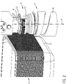
- FIG 1 shows an unstacking device 1 according to the invention, which is configured to drop trays individually onto a transport unit 2 in order to subsequently feed the trays, also referred to as trays, to a filling station or insertion station of a packaging machine.
- the unstacking device 1 has vertical guides 3 in order to 2 Stack 4 of shells 5 shown in more detail.
- Four destacking screws 6 are driven by a common motor 7, preferably a servo motor.
- Two destacking screws 6 are attached to a common transmission shaft, not described in detail, by means of a gear 8 for each destacking screw 6 and can be displaced along this transmission shaft in order to be adaptable to different shell sizes.
- a shell relief device 10 see 2 , provided in order to hold or raise the stack 4 and thus reduce the force of the stack 4 on the destacking screws 6 or the bottom shell 5 .
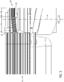
- FIG 2 shows an enlarged view of a separating device 11 for unstacking individual shells 5 from the stack 4.
- the separating device 11 has the destacking screw 6 with axis of rotation A for this purpose.
- the shell relief device 10 is provided on the common axis A above the separating device 11 .
- the shell relief device 10 has a lifting element 12 which rotates about the axis A and together or synchronously with the destacking screw 6 .
- the lifting element 12 has a substantially cylindrical shape.
- a comb structure K with five immersion projections 13 running parallel to one another is provided on its outside, which extend over an area of approximately 270° along the circumference of the lifting element 12 .
- the immersion projections 13 gradually rise in a helical manner in a region 14 in the axial direction and then run horizontally in a region 16 .
- rising area 14 is used to lift the stack 4 and the optional falling area is used to gently lower the stack 4 onto the uppermost immersion projection 13 of the destacking screws 6.
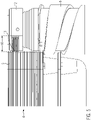
- FIG 3 shows a side view of the shell relief device 10 in a first phase, in which the lifting element 12 begins to rotate in the direction of the arrow or clockwise.
- the immersion projections 13 of the comb structure K are still radially away from the shell edges 15, preferably by 0.1 to 1.0 mm.
- the immersion projections 13 themselves each have a preferred vertical spacing of 2 to 4 mm from one another in order to be able to individually accommodate shells 15 lying close to one another and one inside the other at their shell edges 15 .
- figure 4 shows a second phase in which the rotating immersion projections 13 immerse themselves in the stack 4 in that the height of the immersion projections 13, ie their radial distances D from the axis A, increase and the shells 5 or their shell edges 15 are at least partially pushed apart or else just raise.
- the destacking screw 6 is conveyed downwards.
- At least two shells 5 should be grasped by immersion projections 13 and cause the stack 4 to be lifted in order to distribute the load on the shells 5 to the immersion projections 13 in order to prevent the stack 4 from slipping, especially at a low immersion depth of 1 to 3 mm
- the region 16 of the immersion projections 13 which follows in the opposite direction to the direction of rotation is formed horizontally with the axis A aligned vertically in order to hold the stack 4 in the raised position.
- the immersion projections 13 again reduce their radial distance to the axis A and emerge from the stack 4, so that the lifted stack 4 slides down onto the shells 5 below, before the process described above begins again.
- the horizontal area 16 see figure 5 , followed by a sloping area not shown in detail. The horizontal area 16 is thereby shortened.
- the unstacking screws 6 with the lifting elements 12 arranged on the common axis A can be provided in the vicinity of the four corners of the stack 4, respectively. They can be distributed on four sides or on two opposite sides of a rectangular stack 4, for example.
Landscapes
- Engineering & Computer Science (AREA)
- Mechanical Engineering (AREA)
- Physics & Mathematics (AREA)
- General Physics & Mathematics (AREA)
- De-Stacking Of Articles (AREA)
- Centrifugal Separators (AREA)
Description
- Die Erfindung bezieht sich auf eine Entstapelvorrichtung zum Entstapeln von einzelnen Schalen mit einer rotierenden Trayentlastung gemäß dem Anspruch 1.
- Aus der
WO 2015/028022 A1 ist eine Entstapelvorrichtung nach dem Oberbegriff des Anspruchs 1 bekannt, bei der eine Taumelscheibe derart und zusammen mit einer Entstaplerschraube auf einer rotierenden Achse angeordnet ist, dass bei einer Drehung von 360° die Taumelscheibe in einen Traystapel oberhalb der Entstaplerschraube zwischen zwei übereinander benachbarten Schalen, auch Trays genannt, bzw. deren Schalenränder eintaucht und die an der Oberseite der Taumelscheibe aufliegende Schale zusammen mit dem darüber befindlichen Stapel von Schalen anhebt. So wird die Belastung auf die unterste, zu entstapelnde Schale auf ein konstantes Minimum reduziert. Aufgrund von unterschiedlichen Stapelhöhen entstehen auf die im Bereich der Taumelscheibe befindlichen Schalen unterschiedliche Belastungen, welche zu unterschiedlichen vertikalen Abständen zwischen zwei benachbarten und ineinander liegenden Schalen führen können. Da kann es vorkommen, dass die im Stand der Technik offenbarten Taumelscheiben, die jeweils an den Ecken oder an gegenüberliegenden Seiten der Schalen vorgesehen sind, nicht eine einzige gemeinsame Schale anheben, sondern zwei übereinander befindliche Schalen einseitig oder zumindest nicht allseitig anheben und somit nicht die gesamte Last des Traystapels aufgenommen wird. - Die
US 3,454,987 A ,WO 2009/150755 A1 ,CN 105460626 A undEP 3 023 370 A1 offenbaren jeweils Entstapelvorrichtungen zum Entstapeln von in einem Stapel zusammengefügter Behälter, beispielsweise in Form von Schalen oder Bechern. - Aufgabe der Erfindung ist es, eine verbesserte Ausführungsform einer Trayentlastung bereitzustellen.
- Diese Aufgabe wird gelöst durch eine Entstapelvorrichtung mit den Merkmalen des Anspruchs 1. Vorteilhafte Weiterbildungen der Erfindung sind in den Unteransprüchen angegeben.
- Die erfindungsgemäße Entstapelvorrichtung zum Entstapeln von Schalen umfasst Vertikalführungen zum Aufnehmen eines Stapels mit einer Vielzahl von Schalen, eine Trennvorrichtung zum Abstapeln von einzelnen Schalen nach unten und eine Schalenentlastungsvorrichtung, die mehrere rotierende Anhebeelemente aufweist. Die erfindungsgemäße Entstapelvorrichtung zeichnet sich dadurch aus, dass die Anhebeelemente im Wesentlichen zylindrisch ausgebildet sind und eine Kammstruktur mit wenigstens zwei im Wesentlichen in Umfangsrichtung der Anhebeelemente zueinander parallel verlaufenden Eintauchvorsprünge aufweisen. Dies bringt den Vorteil mit sich, z.B. auch Menüschalen verarbeiten zu können, die derart ineinander gestapelt sind, dass die Schalen lediglich an der äußersten Kante angehoben werden können und die Eintauchtiefe in den Stapel weniger als 2 mm betragen kann. Solche Menüschalen können auch eine geringe Stabilität am Schalenrand aufweisen, so dass ein Umknicken und damit ein Durchrutschen am Anhebeelement nicht ausgeschlossen werden kann. Durch das gleichzeitige Aufnehmen mehrerer Schalen des Stapels mittels mehrerer Eintauchvorsprünge wird ein Durchrutschen des Stapels trotz der sehr geringen Eintauchtiefe verhindert, da eine Lastverteilung des Stapels auf mehrere Eintauchvorsprünge der Kammstruktur vorliegt.
- Bevorzugt weisen die Kammstrukturen der Anhebeelemente wenigstens vier zueinander parallel verlaufende Eintauchvorsprünge auf, um die Gewichtsverteilung des Stapels verbessert zu verteilen.
- Vorzugsweise weisen zwei benachbarte Eintauchvorsprünge einen Abstand von 2 mm bis 4 mm auf, um auch einen Stapel mit ineinander liegenden Schalen, deren Schalenränder die Oberseite einer unterhalb befindlichen Schale überlappen, verarbeiten bzw. anheben zu können.
- Dabei weisen die Eintauchvorsprünge in einer besonders vorteilhaften Ausführung einen gleichen Abstand zueinander auf; so ist sowohl eine Gewichtsverteilung auf wenigstens zwei Eintauchvorsprünge als auch eine Verarbeitung von Standardschalen mit größeren Abständen der Schalen zueinander und tiefer eintauchenden Eintauchvorsprüngen ermöglicht.
- In einer besonders vorteilhaften Ausführung weisen die Eintauchvorsprünge einen schraubenförmig ansteigenden und einen horizontal verlaufenden sowie optional einen abfallenden Bereich auf, um sowohl den Stapel sanft anzuheben als auch sanft in die Ursprungslage abzusenken, womit ein besonders ruhiger Arbeitsablauf gewährleistet werden kann.
- Die Eintauchvorsprünge erstrecken sich in umlaufender Richtung vorzugsweise über einen Bereich von weniger als 315°, bevorzugt weniger als 270°, um den Eintauchvorsprung aus dem Stapel herauszuführen, damit der Stapel nach unten nachgeführt werden kann.
- Die Erfindung sieht vor, dass der Stapel bei einer Drehung des Anhebeelements um 360° temporär um wenigstens 3 mm angehoben wird.
- Im Folgenden wird ein vorteilhaftes Ausführungsbeispiel der Erfindung anhand von Zeichnungen näher dargestellt. Im Einzelnen zeigen:
-
Fig. 1 eine Entstapelvorrichtung und eine Transporteinheit, -
Fig. 2 eine vergrößerte Ansicht einer Schalenentlastungsvorrichtung, -
Fig. 3 eine Seitenansicht der Schalenentlastungsvorrichtung in einer ersten Phase, -
Fig. 4 eine Seitenansicht der Schalenentlastungsvorrichtung in einer zweiten Phase, -
Fig. 5 eine Seitenansicht der Schalenentlastungsvorrichtung in einer dritten Phase und -
Fig. 6 eine Seitenansicht der Schalenentlastungsvorrichtung in einer vierten Phase. - Gleiche Komponenten sind in den Figuren durchgängig mit gleichen Bezugszeichen versehen worden.
-
Figur 1 zeigt eine erfindungsgemäße Entstapelvorrichtung 1, die konfiguriert ist, um Schalen einzeln auf eine Transporteinheit 2 fallen zu lassen, um die Schalen, auch als Trays bezeichnet, anschließend einer Füllstation oder Einlegestation einer Verpackungsmaschine zuzuführen. Die Entstapelvorrichtung 1 weist Vertikalführungen 3 auf, um einen inFig. 2 näher gezeigten Stapel 4 von Schalen 5 aufzunehmen. Vier Entstaplerschrauben 6 werden von einem gemeinsamen Motor 7, vorzugsweise von einem Servomotor, angetrieben. Jeweils zwei Entstaplerschrauben 6 sind mittels jeweils eines Getriebes 8 für jede Entstaplerschraube 6 auf einer gemeinsamen, nicht näher beschriebenen Getriebewelle angebracht und entlang dieser Getriebewelle verschiebbar, um an unterschiedliche Schalengrößen anpassbar zu sein. Auf jeder der vier Achsen der Entstaplerschrauben 6 ist eine Schalenentlastungsvorrichtung 10, sieheFig. 2 , vorgesehen, um den Stapel 4 zu halten bzw. anzuheben und somit die Kraft des Stapels 4 auf die Entstaplerschrauben 6 bzw. die unterste Schale 5 zu reduzieren. -
Figur 2 zeigt eine vergrößerte Ansicht einer Trennvorrichtung 11 zum Abstapeln einzelner Schalen 5 vom Stapel 4. Die Trennvorrichtung 11 weist hierfür die Entstaplerschraube 6 mit Drehachse A auf. Oberhalb der Trennvorrichtung 11 ist die Schalenentlastungsvorrichtung 10 auf der gemeinsamen Achse A vorgesehen. Die Schalenentlastungsvorrichtung 10 weist ein um die Achse A und gemeinsam bzw. synchron mit der Entstaplerschraube 6 rotierendes Anhebeelement 12 auf. Das Anhebeelement 12 weist eine im Wesentlichen zylindrische Form auf. An seiner Außenseite ist eine Kammstruktur K mit fünf parallel zueinander verlaufenden Eintauchvorsprüngen 13 vorgesehen, die sich über einen Bereich von ca. 270° entlang des Umgangs des Anhebeelements 12 erstrecken. Dabei verlaufen die Eintauchvorsprünge 13 in einem Bereich 14 in axialer Richtung allmählich schraubenförmig ansteigend und anschließend in einem Bereich 16 horizontal. Denkbar ist auch ein ansteigender Bereich 14 und ein später folgender abfallender Bereich. Der ansteigende Bereich 14 dient zum Anheben des Stapels 4 und der optionale abfallende Bereich zum sanften Absetzen des Stapels 4 auf den obersten Eintauchvorsprung 13 der Entstaplerschrauben 6. In den folgenden Figuren werden verschiedene Phasen, die innerhalb einer Drehung des Anhebeelements 12 auftreten, näher erläutert. -
Figur 3 zeigt eine Seitenansicht der Schalenentlastungsvorrichtung 10 in einer ersten Phase, bei der das Anhebelement 12 sich in Pfeilrichtung bzw. im Uhrzeigersinn zu drehen beginnt. Die Eintauchvorsprünge 13 der Kammstruktur K sind zu Beginn des ansteigenden Bereichs 14 radial noch von den Schalenrändern 15 vorzugsweise um 0,1 bis 1,0 mm entfernt. Die Eintauchvorsprünge 13 selbst weisen jeweils einen bevorzugten vertikalen Abstand von 2 bis 4 mm zueinander auf, um auch eng aufeinander- und ineinander liegende Schalen 15 an deren Schalenrändern 15 einzeln aufnehmen zu können. -
Figur 4 zeigt eine zweite Phase, bei der die rotierenden Eintauchvorsprünge 13 derart in den Stapel 4 eintauchen, indem die Höhe der Eintauchvorsprünge 13, d. h. ihre radialen Abstände D von der Achse A zunehmen und dabei die Schalen 5 bzw. deren Schalenränder 15 wenigstens teilweise auseinanderdrücken oder auch nur anheben. Eine bereits zuvor durch die Entstaplerschraube 6 vom Stapel 4 abgelöste, unterste Schale 5 wird hingegen nach unten gefördert. - In der weiteren rotativen Bewegung des Anhebeelements 12 werden, wie in
Figur 5 in einer dritten Phase gezeigt, der Stapel 4 bzw. die von den Eintauchvorsprüngen 13 erfassten Schalen 5 weiter angehoben und somit die Last des Stapels 4 von den zwischen der Schalenentlastungsvorrichtung 10 und der Entstaplerschraube 6 befindlichen Anzahl von Schalen 5 reduziert bzw. komplett abgenommen. Dies minimiert bzw. begrenzt die Last bzw. Gewichtskraft auf die unterste Schale 5 vor oder beim Entstapeln durch die Entstaplerschraube 6. Je nach Abstand der Schalen 5 im Stapel 4 zueinander tragen alle Eintauchvorsprünge 13 je eine Schale 5 oder es kann auch eine Lücke entstehen und nicht alle Eintauchvorsprünge 13 heben eine Schale 5 an. Wenigstens zwei Schalen 5 sollten von Eintauchvorsprüngen 13 erfasst werden und das Anheben des Stapels 4 bewirken, um die Belastung der Schalen 5 auf die Eintauchvorsprünge 13 zu verteilen, um so ein Durchrutschen des Stapels 4 vor allem bei einer geringen Eintauchtiefe von 1 bis 3 mm der Eintauchvorsprünge 13 in den Stapel 4 bzw. unter die Schalenränder 15 zu verhindern. Der entgegen der Drehrichtung folgende Bereich 16 der Eintauchvorsprünge 13 ist horizontal ausgebildet bei vertikal ausgerichteter Achse A, um den Stapel 4 in der angehobenen Position zu halten. - In der
Figur 6 ist gezeigt, wie in der vierten und letzten Phase vor Beendigung einer kompletten 360° Drehung die Eintauchvorsprünge 13 wiederum ihren radialen Abstand zur Achse A verringern und aus dem Stapel 4 austauchen, so dass der angehobene Stapel 4 nach unten auf die darunterliegenden Schalen 5 nachrutscht, bevor der zuvor beschriebene Ablauf wieder von neuem beginnt. Um das Absetzen möglichst sanft gestalten zu können, kann auf den horizontalen Bereich 16, sieheFigur 5 , ein nicht näher gezeigter abfallender Bereich folgen. Dabei wird der horizontale Bereich 16 verkürzt. - Die Entstaplerschrauben 6 mit den auf der gemeinsamen Achse A angeordneten Anhebelementen 12 können jeweils in der Nähe der vier Ecken des Stapels 4 vorgesehen sein. Dabei können sie beispielsweise verteilt auf vier Seiten oder an zwei gegenüberliegenden Seiten eines rechteckigen Stapels 4 angeordnet sein.
Claims (8)
- Entstapelvorrichtung (1) zum Entstapeln von Schalen (5), umfassend Vertikalführungen (3) zum Aufnehmen eines Stapels (4) mit einer Vielzahl von Schalen (5), eine Trennvorrichtung (11) zum Abstapeln von einzelnen Schalen (5) nach unten und eine Schalenentlastungsvorrichtung (10), dadurch gekennziechnet, dass die Schalenentlastungsvorrichtung (10) mehrere jeweils um eine Achse (A) rotierende Anhebeelemente (12) aufweist, die im Wesentlichen zylindrisch ausgebildet sind und jeweils auf ihrer Außenseite eine Kammstruktur (K) mit wenigstens zwei zueinander parallel verlaufenden Eintauchvorsprüngen (13) aufweisen.
- Entstapelvorrichtung nach Anspruch 1, dadurch gekennzeichnet, dass die Anhebeelemente (12) wenigstens vier oder fünf zueinander parallel verlaufende Eintauchvorsprünge (13) aufweisen.
- Entstapelvorrichtung nach einem der vorangehenden Ansprüche, dadurch gekennzeichnet, dass zwei benachbarte Eintauchvorsprünge (13) einen Abstand von 2 bis 4 mm aufweisen.
- Entstapelvorrichtung nach einem der vorangehenden Ansprüche, dadurch gekennzeichnet, dass die Eintauchvorsprünge (13) einen gleichen Abstand zueinander aufweisen.
- Entstapelvorrichtung nach einem der vorangehenden Ansprüche, dadurch gekennzeichnet, dass sich die Eintauchvorsprünge (13) in umlaufender Richtung über einen Bereich von weniger als 270° der Anhebeelemente (12) erstrecken.
- Entstapelvorrichtung nach einem der vorangehenden Ansprüche, dadurch gekennzeichnet, dass die Eintauchvorsprünge (13) einen schraubenförmig ansteigenden Bereich (14) und einen horizontalen Bereich (16) aufweisen, optional gefolgt von einem abfallenden Bereich.
- Entstapelvorrichtung nach einem der vorangehenden Ansprüche, dadurch gekennzeichnet, dass die Eintauchvorsprünge (13) über ihren Verlauf einen variierenden radialen Abstand (D) von der Achse (A) aufweisen.
- Entstapelvorrichtung nach wenigstens den Ansprüchen 6 und 7, dadurch gekennzeichnet, dass der radiale Abstand (D) eines Eintauchvorsprungs (13) von der Achse (A) im Verlauf seines ansteigenden Bereichs (14) zunimmt und im Verlauf seines horizontalen Bereichs (16) zumindest weitgehend konstant bleibt.
Priority Applications (4)
| Application Number | Priority Date | Filing Date | Title |
|---|---|---|---|
| DK17156414.9T DK3363752T3 (da) | 2017-02-16 | 2017-02-16 | Afstablerindretning med roterende bakkeaflastning |
| ES17156414T ES2928003T3 (es) | 2017-02-16 | 2017-02-16 | Dispositivo de desapilado con descargador de bandejas giratorio |
| EP17156414.9A EP3363752B1 (de) | 2017-02-16 | 2017-02-16 | Entstapelvorrichtung mit rotierender schalenentlastung |
| US15/895,947 US10549933B2 (en) | 2017-02-16 | 2018-02-13 | Dispensing device with rotating tray discharge with stack weight relief |
Applications Claiming Priority (1)
| Application Number | Priority Date | Filing Date | Title |
|---|---|---|---|
| EP17156414.9A EP3363752B1 (de) | 2017-02-16 | 2017-02-16 | Entstapelvorrichtung mit rotierender schalenentlastung |
Publications (2)
| Publication Number | Publication Date |
|---|---|
| EP3363752A1 EP3363752A1 (de) | 2018-08-22 |
| EP3363752B1 true EP3363752B1 (de) | 2022-08-17 |
Family
ID=58094224
Family Applications (1)
| Application Number | Title | Priority Date | Filing Date |
|---|---|---|---|
| EP17156414.9A Active EP3363752B1 (de) | 2017-02-16 | 2017-02-16 | Entstapelvorrichtung mit rotierender schalenentlastung |
Country Status (4)
| Country | Link |
|---|---|
| US (1) | US10549933B2 (de) |
| EP (1) | EP3363752B1 (de) |
| DK (1) | DK3363752T3 (de) |
| ES (1) | ES2928003T3 (de) |
Families Citing this family (10)
| Publication number | Priority date | Publication date | Assignee | Title |
|---|---|---|---|---|
| JP6588513B2 (ja) * | 2017-09-05 | 2019-10-09 | ファナック株式会社 | ワーク取り出し装置 |
| CN109132577A (zh) * | 2018-08-20 | 2019-01-04 | 南通通机股份有限公司 | 一种新型塑料托盒自动分离系统 |
| CN110498241A (zh) * | 2019-08-03 | 2019-11-26 | 广东智源机器人科技有限公司 | 出餐输送系统、出盘装置及分盘机构 |
| EP3936467A1 (de) * | 2020-07-09 | 2022-01-12 | Selfcair UK Ltd | Tablettrückführungsmodul für eine inspektionseinrichtung und inspektionseinrichtung mit mindestens einem solchen modul |
| WO2022096581A1 (en) | 2020-11-04 | 2022-05-12 | Js Stål Aps | Destacker unit and system for destacking of objects |
| CN112499203B (zh) * | 2020-12-04 | 2024-12-10 | 苏州领裕电子科技有限公司 | 皮带线料仓自动进出料设备 |
| KR102531178B1 (ko) * | 2021-03-29 | 2023-05-10 | (주)크레템 | 블리스터 팩용 블리스터 시트 공급 유닛 및 이를 구비한 약제의 블리스터 팩킹 장치 |
| US11884197B2 (en) * | 2021-07-19 | 2024-01-30 | Nicholas P. Carter | Systems and methods of automated deployment of mounting devices for photovoltaic modules for solar plant installation |
| US12440045B2 (en) * | 2021-09-14 | 2025-10-14 | Cfs Brands, Llc | Disposable lid dispenser assembly |
| CN118025556A (zh) * | 2024-04-01 | 2024-05-14 | 九江市永信制罐设备有限公司 | 一种罐体封盖过程中同步连续落盖供应装置 |
Family Cites Families (16)
| Publication number | Priority date | Publication date | Assignee | Title |
|---|---|---|---|---|
| US3454987A (en) * | 1966-09-27 | 1969-07-15 | Illinois Tool Works | Apparatus for separating rim nested containers |
| US3741410A (en) * | 1971-03-24 | 1973-06-26 | Ekco Prod Inc | Separator |
| US4108319A (en) * | 1977-02-22 | 1978-08-22 | Ppg Industries, Inc. | Glass accumulator |
| US4180180A (en) * | 1978-01-16 | 1979-12-25 | International Paper Company | Apparatus and method for automatically dispensing flexible containers |
| US4884795A (en) * | 1988-05-26 | 1989-12-05 | Bell & Howell Company | Document feeder apparatus |
| IT1285438B1 (it) * | 1996-01-09 | 1998-06-08 | Azionaria Costruzioni Acma Spa | Metodo ed unita' per la formazione di pile di articoli |
| IT1292842B1 (it) * | 1997-04-08 | 1999-02-11 | Azionaria Costruzioni Acma Spa | Impianto per il confezionamento di prodotti. |
| US20020017447A1 (en) * | 2000-03-16 | 2002-02-14 | Emigh Jonathan D. | Apparatus and method for stacking flat articles on-edge in a horizontal row |
| DE102007034391A1 (de) * | 2007-07-24 | 2009-02-05 | Siemens Ag | Vorrichtung zum Ausrichten flacher Gegenstände mittels eines Spindelgewindes |
| WO2009150755A1 (ja) * | 2008-06-13 | 2009-12-17 | 株式会社高井製作所 | 積載パックからのパック取り出し装置及びこの装置を使用した豆腐類のパック詰め方法 |
| FI121268B (fi) * | 2008-11-13 | 2010-09-15 | Antti Lindfors Oy | Purkuelin ja purkulaite rasiapinon purkamiseksi |
| GB2468667A (en) * | 2009-03-17 | 2010-09-22 | Herbert R J Eng Ltd | Tray lift comprising elevator screws |
| DK177779B1 (da) | 2013-08-28 | 2014-06-30 | Intech Internat A S | Dispenseringsapparat samt anvendelse |
| DK178264B1 (da) * | 2014-09-04 | 2015-10-19 | Intech Internat A S | Dispenseringsapparat samt anvendelse |
| EP3023370B1 (de) * | 2014-11-18 | 2017-08-09 | MULTIVAC Sepp Haggenmüller SE & Co. KG | Denester mit verstellbarem Schrägmagazin |
| CN105460626B (zh) * | 2015-12-25 | 2018-01-16 | 江苏大学 | 一种设施园艺花盆自动卸放装置和方法 |
-
2017
- 2017-02-16 EP EP17156414.9A patent/EP3363752B1/de active Active
- 2017-02-16 DK DK17156414.9T patent/DK3363752T3/da active
- 2017-02-16 ES ES17156414T patent/ES2928003T3/es active Active
-
2018
- 2018-02-13 US US15/895,947 patent/US10549933B2/en active Active
Also Published As
| Publication number | Publication date |
|---|---|
| EP3363752A1 (de) | 2018-08-22 |
| ES2928003T3 (es) | 2022-11-14 |
| US10549933B2 (en) | 2020-02-04 |
| US20180229949A1 (en) | 2018-08-16 |
| DK3363752T3 (da) | 2022-11-07 |
Similar Documents
| Publication | Publication Date | Title |
|---|---|---|
| EP3363752B1 (de) | Entstapelvorrichtung mit rotierender schalenentlastung | |
| EP3246277B1 (de) | Abstapelvorrichtung für schalen | |
| EP3511273B1 (de) | Abstapelvorrichtung für schalen | |
| EP4121373A1 (de) | Sortiervorrichtung | |
| EP3889079B1 (de) | Verfahren und anlage zum bilden von stapeln aus stabförmigen gegenständen | |
| EP3023370B1 (de) | Denester mit verstellbarem Schrägmagazin | |
| EP3187442A1 (de) | Denester | |
| EP2637808A1 (de) | Fördereinrichtung zum fördern von werkstücken | |
| EP3292753B1 (de) | Entladesystem und verfahren zum entladen von transporteinheiten für lebendige geflügeltiere | |
| DE3403550C2 (de) | Transport- und Lagergestell | |
| DE102021131446B4 (de) | Stapelentpacker und Verfahren zu dessen Betrieb | |
| DE69204797T2 (de) | Verbesserung in einer Behälterpositioniermaschine. | |
| WO2000034165A1 (de) | Vorrichtung und verfahren zum bilden und portionieren eines stapels | |
| DE3444093C2 (de) | ||
| EP3024767A1 (de) | Adapterpalette für stapelvorrichtung | |
| DE19711464C2 (de) | Verfahren zum Stapeln von Transportkisten und Transportkistenstapellager | |
| EP2253565A2 (de) | Stapelvorrichtung zum Stapeln von Werkstücken aus Holz, Kunststoff oder dergleichen sowie Verfahren hierfür | |
| DE3633602C1 (en) | Pick up device for thin, flexible strips | |
| DE19540992A1 (de) | Vorrichtung zum ausgerichteten Zuführen und Auflockern von Stapeln flacher Gegenstände | |
| EP1440923B1 (de) | Anordnung und Verfahren zum sortierten Abstapeln von in Form und/oder Grösse unterschiedlicher Lagen aus blattförmigen Materialien | |
| DE2318721A1 (de) | Auswerfervorrichtung fuer konische becher | |
| DE2210383A1 (de) | Vorrichtung zum kreuzweisen stapeln und entstapeln von stapelgut, insbesondere lattenscharen | |
| DE3137236A1 (de) | Vorrichtung zum flexiblen vereinzeln platinenaehnlicher werkstuecke | |
| DE102009026188A1 (de) | Magazin zum Speichern von flächigen Elementen, Verpackungseinrichtung, Verfahren zum Betreiben von Magazinen | |
| DE2519183A1 (de) | Abstapel- und vereinzelungseinrichtung fuer stapelfaehige dosendeckel |
Legal Events
| Date | Code | Title | Description |
|---|---|---|---|
| PUAI | Public reference made under article 153(3) epc to a published international application that has entered the european phase |
Free format text: ORIGINAL CODE: 0009012 |
|
| STAA | Information on the status of an ep patent application or granted ep patent |
Free format text: STATUS: THE APPLICATION HAS BEEN PUBLISHED |
|
| AK | Designated contracting states |
Kind code of ref document: A1 Designated state(s): AL AT BE BG CH CY CZ DE DK EE ES FI FR GB GR HR HU IE IS IT LI LT LU LV MC MK MT NL NO PL PT RO RS SE SI SK SM TR |
|
| AX | Request for extension of the european patent |
Extension state: BA ME |
|
| STAA | Information on the status of an ep patent application or granted ep patent |
Free format text: STATUS: REQUEST FOR EXAMINATION WAS MADE |
|
| 17P | Request for examination filed |
Effective date: 20190213 |
|
| RBV | Designated contracting states (corrected) |
Designated state(s): AL AT BE BG CH CY CZ DE DK EE ES FI FR GB GR HR HU IE IS IT LI LT LU LV MC MK MT NL NO PL PT RO RS SE SI SK SM TR |
|
| RIC1 | Information provided on ipc code assigned before grant |
Ipc: B65B 43/44 20060101ALN20220117BHEP Ipc: B65G 59/10 20060101AFI20220117BHEP |
|
| GRAP | Despatch of communication of intention to grant a patent |
Free format text: ORIGINAL CODE: EPIDOSNIGR1 |
|
| STAA | Information on the status of an ep patent application or granted ep patent |
Free format text: STATUS: GRANT OF PATENT IS INTENDED |
|
| INTG | Intention to grant announced |
Effective date: 20220322 |
|
| GRAS | Grant fee paid |
Free format text: ORIGINAL CODE: EPIDOSNIGR3 |
|
| GRAA | (expected) grant |
Free format text: ORIGINAL CODE: 0009210 |
|
| STAA | Information on the status of an ep patent application or granted ep patent |
Free format text: STATUS: THE PATENT HAS BEEN GRANTED |
|
| AK | Designated contracting states |
Kind code of ref document: B1 Designated state(s): AL AT BE BG CH CY CZ DE DK EE ES FI FR GB GR HR HU IE IS IT LI LT LU LV MC MK MT NL NO PL PT RO RS SE SI SK SM TR |
|
| REG | Reference to a national code |
Ref country code: CH Ref legal event code: EP |
|
| REG | Reference to a national code |
Ref country code: DE Ref legal event code: R096 Ref document number: 502017013617 Country of ref document: DE |
|
| REG | Reference to a national code |
Ref country code: IE Ref legal event code: FG4D Free format text: LANGUAGE OF EP DOCUMENT: GERMAN |
|
| REG | Reference to a national code |
Ref country code: AT Ref legal event code: REF Ref document number: 1512056 Country of ref document: AT Kind code of ref document: T Effective date: 20220915 |
|
| REG | Reference to a national code |
Ref country code: NL Ref legal event code: FP |
|
| REG | Reference to a national code |
Ref country code: DK Ref legal event code: T3 Effective date: 20221103 |
|
| REG | Reference to a national code |
Ref country code: ES Ref legal event code: FG2A Ref document number: 2928003 Country of ref document: ES Kind code of ref document: T3 Effective date: 20221114 |
|
| REG | Reference to a national code |
Ref country code: LT Ref legal event code: MG9D |
|
| PG25 | Lapsed in a contracting state [announced via postgrant information from national office to epo] |
Ref country code: SE Free format text: LAPSE BECAUSE OF FAILURE TO SUBMIT A TRANSLATION OF THE DESCRIPTION OR TO PAY THE FEE WITHIN THE PRESCRIBED TIME-LIMIT Effective date: 20220817 Ref country code: RS Free format text: LAPSE BECAUSE OF FAILURE TO SUBMIT A TRANSLATION OF THE DESCRIPTION OR TO PAY THE FEE WITHIN THE PRESCRIBED TIME-LIMIT Effective date: 20220817 Ref country code: PT Free format text: LAPSE BECAUSE OF FAILURE TO SUBMIT A TRANSLATION OF THE DESCRIPTION OR TO PAY THE FEE WITHIN THE PRESCRIBED TIME-LIMIT Effective date: 20221219 Ref country code: NO Free format text: LAPSE BECAUSE OF FAILURE TO SUBMIT A TRANSLATION OF THE DESCRIPTION OR TO PAY THE FEE WITHIN THE PRESCRIBED TIME-LIMIT Effective date: 20221117 Ref country code: LV Free format text: LAPSE BECAUSE OF FAILURE TO SUBMIT A TRANSLATION OF THE DESCRIPTION OR TO PAY THE FEE WITHIN THE PRESCRIBED TIME-LIMIT Effective date: 20220817 Ref country code: LT Free format text: LAPSE BECAUSE OF FAILURE TO SUBMIT A TRANSLATION OF THE DESCRIPTION OR TO PAY THE FEE WITHIN THE PRESCRIBED TIME-LIMIT Effective date: 20220817 Ref country code: FI Free format text: LAPSE BECAUSE OF FAILURE TO SUBMIT A TRANSLATION OF THE DESCRIPTION OR TO PAY THE FEE WITHIN THE PRESCRIBED TIME-LIMIT Effective date: 20220817 |
|
| PG25 | Lapsed in a contracting state [announced via postgrant information from national office to epo] |
Ref country code: PL Free format text: LAPSE BECAUSE OF FAILURE TO SUBMIT A TRANSLATION OF THE DESCRIPTION OR TO PAY THE FEE WITHIN THE PRESCRIBED TIME-LIMIT Effective date: 20220817 Ref country code: IS Free format text: LAPSE BECAUSE OF FAILURE TO SUBMIT A TRANSLATION OF THE DESCRIPTION OR TO PAY THE FEE WITHIN THE PRESCRIBED TIME-LIMIT Effective date: 20221217 Ref country code: HR Free format text: LAPSE BECAUSE OF FAILURE TO SUBMIT A TRANSLATION OF THE DESCRIPTION OR TO PAY THE FEE WITHIN THE PRESCRIBED TIME-LIMIT Effective date: 20220817 Ref country code: GR Free format text: LAPSE BECAUSE OF FAILURE TO SUBMIT A TRANSLATION OF THE DESCRIPTION OR TO PAY THE FEE WITHIN THE PRESCRIBED TIME-LIMIT Effective date: 20221118 |
|
| PG25 | Lapsed in a contracting state [announced via postgrant information from national office to epo] |
Ref country code: SM Free format text: LAPSE BECAUSE OF FAILURE TO SUBMIT A TRANSLATION OF THE DESCRIPTION OR TO PAY THE FEE WITHIN THE PRESCRIBED TIME-LIMIT Effective date: 20220817 Ref country code: RO Free format text: LAPSE BECAUSE OF FAILURE TO SUBMIT A TRANSLATION OF THE DESCRIPTION OR TO PAY THE FEE WITHIN THE PRESCRIBED TIME-LIMIT Effective date: 20220817 Ref country code: CZ Free format text: LAPSE BECAUSE OF FAILURE TO SUBMIT A TRANSLATION OF THE DESCRIPTION OR TO PAY THE FEE WITHIN THE PRESCRIBED TIME-LIMIT Effective date: 20220817 |
|
| REG | Reference to a national code |
Ref country code: DE Ref legal event code: R097 Ref document number: 502017013617 Country of ref document: DE |
|
| PG25 | Lapsed in a contracting state [announced via postgrant information from national office to epo] |
Ref country code: SK Free format text: LAPSE BECAUSE OF FAILURE TO SUBMIT A TRANSLATION OF THE DESCRIPTION OR TO PAY THE FEE WITHIN THE PRESCRIBED TIME-LIMIT Effective date: 20220817 Ref country code: EE Free format text: LAPSE BECAUSE OF FAILURE TO SUBMIT A TRANSLATION OF THE DESCRIPTION OR TO PAY THE FEE WITHIN THE PRESCRIBED TIME-LIMIT Effective date: 20220817 |
|
| PLBE | No opposition filed within time limit |
Free format text: ORIGINAL CODE: 0009261 |
|
| STAA | Information on the status of an ep patent application or granted ep patent |
Free format text: STATUS: NO OPPOSITION FILED WITHIN TIME LIMIT |
|
| PG25 | Lapsed in a contracting state [announced via postgrant information from national office to epo] |
Ref country code: AL Free format text: LAPSE BECAUSE OF FAILURE TO SUBMIT A TRANSLATION OF THE DESCRIPTION OR TO PAY THE FEE WITHIN THE PRESCRIBED TIME-LIMIT Effective date: 20220817 |
|
| 26N | No opposition filed |
Effective date: 20230519 |
|
| PG25 | Lapsed in a contracting state [announced via postgrant information from national office to epo] |
Ref country code: SI Free format text: LAPSE BECAUSE OF FAILURE TO SUBMIT A TRANSLATION OF THE DESCRIPTION OR TO PAY THE FEE WITHIN THE PRESCRIBED TIME-LIMIT Effective date: 20220817 |
|
| P01 | Opt-out of the competence of the unified patent court (upc) registered |
Effective date: 20230801 |
|
| PG25 | Lapsed in a contracting state [announced via postgrant information from national office to epo] |
Ref country code: MC Free format text: LAPSE BECAUSE OF FAILURE TO SUBMIT A TRANSLATION OF THE DESCRIPTION OR TO PAY THE FEE WITHIN THE PRESCRIBED TIME-LIMIT Effective date: 20220817 |
|
| REG | Reference to a national code |
Ref country code: CH Ref legal event code: PL |
|
| REG | Reference to a national code |
Ref country code: BE Ref legal event code: MM Effective date: 20230228 |
|
| PG25 | Lapsed in a contracting state [announced via postgrant information from national office to epo] |
Ref country code: LU Free format text: LAPSE BECAUSE OF NON-PAYMENT OF DUE FEES Effective date: 20230216 Ref country code: LI Free format text: LAPSE BECAUSE OF NON-PAYMENT OF DUE FEES Effective date: 20230228 Ref country code: CH Free format text: LAPSE BECAUSE OF NON-PAYMENT OF DUE FEES Effective date: 20230228 |
|
| REG | Reference to a national code |
Ref country code: IE Ref legal event code: MM4A |
|
| PG25 | Lapsed in a contracting state [announced via postgrant information from national office to epo] |
Ref country code: IE Free format text: LAPSE BECAUSE OF NON-PAYMENT OF DUE FEES Effective date: 20230216 |
|
| PG25 | Lapsed in a contracting state [announced via postgrant information from national office to epo] |
Ref country code: BE Free format text: LAPSE BECAUSE OF NON-PAYMENT OF DUE FEES Effective date: 20230228 |
|
| REG | Reference to a national code |
Ref country code: AT Ref legal event code: MM01 Ref document number: 1512056 Country of ref document: AT Kind code of ref document: T Effective date: 20230216 |
|
| PG25 | Lapsed in a contracting state [announced via postgrant information from national office to epo] |
Ref country code: AT Free format text: LAPSE BECAUSE OF NON-PAYMENT OF DUE FEES Effective date: 20230216 |
|
| PG25 | Lapsed in a contracting state [announced via postgrant information from national office to epo] |
Ref country code: AT Free format text: LAPSE BECAUSE OF NON-PAYMENT OF DUE FEES Effective date: 20230216 |
|
| PG25 | Lapsed in a contracting state [announced via postgrant information from national office to epo] |
Ref country code: BG Free format text: LAPSE BECAUSE OF FAILURE TO SUBMIT A TRANSLATION OF THE DESCRIPTION OR TO PAY THE FEE WITHIN THE PRESCRIBED TIME-LIMIT Effective date: 20220817 |
|
| PG25 | Lapsed in a contracting state [announced via postgrant information from national office to epo] |
Ref country code: BG Free format text: LAPSE BECAUSE OF FAILURE TO SUBMIT A TRANSLATION OF THE DESCRIPTION OR TO PAY THE FEE WITHIN THE PRESCRIBED TIME-LIMIT Effective date: 20220817 |
|
| PGFP | Annual fee paid to national office [announced via postgrant information from national office to epo] |
Ref country code: NL Payment date: 20250220 Year of fee payment: 9 |
|
| PGFP | Annual fee paid to national office [announced via postgrant information from national office to epo] |
Ref country code: DE Payment date: 20250218 Year of fee payment: 9 |
|
| PGFP | Annual fee paid to national office [announced via postgrant information from national office to epo] |
Ref country code: DK Payment date: 20250219 Year of fee payment: 9 |
|
| PGFP | Annual fee paid to national office [announced via postgrant information from national office to epo] |
Ref country code: ES Payment date: 20250318 Year of fee payment: 9 |
|
| PGFP | Annual fee paid to national office [announced via postgrant information from national office to epo] |
Ref country code: FR Payment date: 20250219 Year of fee payment: 9 |
|
| PGFP | Annual fee paid to national office [announced via postgrant information from national office to epo] |
Ref country code: IT Payment date: 20250228 Year of fee payment: 9 Ref country code: GB Payment date: 20250220 Year of fee payment: 9 |
|
| PG25 | Lapsed in a contracting state [announced via postgrant information from national office to epo] |
Ref country code: CY Free format text: LAPSE BECAUSE OF FAILURE TO SUBMIT A TRANSLATION OF THE DESCRIPTION OR TO PAY THE FEE WITHIN THE PRESCRIBED TIME-LIMIT; INVALID AB INITIO Effective date: 20170216 |
|
| PG25 | Lapsed in a contracting state [announced via postgrant information from national office to epo] |
Ref country code: HU Free format text: LAPSE BECAUSE OF FAILURE TO SUBMIT A TRANSLATION OF THE DESCRIPTION OR TO PAY THE FEE WITHIN THE PRESCRIBED TIME-LIMIT; INVALID AB INITIO Effective date: 20170216 |
|
| PG25 | Lapsed in a contracting state [announced via postgrant information from national office to epo] |
Ref country code: TR Free format text: LAPSE BECAUSE OF FAILURE TO SUBMIT A TRANSLATION OF THE DESCRIPTION OR TO PAY THE FEE WITHIN THE PRESCRIBED TIME-LIMIT Effective date: 20220817 |