EP3362010B1 - Medizinische vorrichtung mit einem öffnungssystem - Google Patents
Medizinische vorrichtung mit einem öffnungssystem Download PDFInfo
- Publication number
- EP3362010B1 EP3362010B1 EP16856364.1A EP16856364A EP3362010B1 EP 3362010 B1 EP3362010 B1 EP 3362010B1 EP 16856364 A EP16856364 A EP 16856364A EP 3362010 B1 EP3362010 B1 EP 3362010B1
- Authority
- EP
- European Patent Office
- Prior art keywords
- reinforcing member
- opening
- outlet
- fastener
- deformable
- Prior art date
- Legal status (The legal status is an assumption and is not a legal conclusion. Google has not performed a legal analysis and makes no representation as to the accuracy of the status listed.)
- Active
Links
Images


Classifications
-
- A—HUMAN NECESSITIES
- A61—MEDICAL OR VETERINARY SCIENCE; HYGIENE
- A61F—FILTERS IMPLANTABLE INTO BLOOD VESSELS; PROSTHESES; DEVICES PROVIDING PATENCY TO, OR PREVENTING COLLAPSING OF, TUBULAR STRUCTURES OF THE BODY, e.g. STENTS; ORTHOPAEDIC, NURSING OR CONTRACEPTIVE DEVICES; FOMENTATION; TREATMENT OR PROTECTION OF EYES OR EARS; BANDAGES, DRESSINGS OR ABSORBENT PADS; FIRST-AID KITS
- A61F5/00—Orthopaedic methods or devices for non-surgical treatment of bones or joints; Nursing devices ; Anti-rape devices
- A61F5/44—Devices worn by the patient for reception of urine, faeces, catamenial or other discharge; Colostomy devices
- A61F5/445—Colostomy, ileostomy or urethrostomy devices
-
- A—HUMAN NECESSITIES
- A61—MEDICAL OR VETERINARY SCIENCE; HYGIENE
- A61F—FILTERS IMPLANTABLE INTO BLOOD VESSELS; PROSTHESES; DEVICES PROVIDING PATENCY TO, OR PREVENTING COLLAPSING OF, TUBULAR STRUCTURES OF THE BODY, e.g. STENTS; ORTHOPAEDIC, NURSING OR CONTRACEPTIVE DEVICES; FOMENTATION; TREATMENT OR PROTECTION OF EYES OR EARS; BANDAGES, DRESSINGS OR ABSORBENT PADS; FIRST-AID KITS
- A61F5/00—Orthopaedic methods or devices for non-surgical treatment of bones or joints; Nursing devices ; Anti-rape devices
- A61F5/44—Devices worn by the patient for reception of urine, faeces, catamenial or other discharge; Colostomy devices
- A61F5/4404—Details or parts
- A61F5/4407—Closure means other than valves
-
- A—HUMAN NECESSITIES
- A61—MEDICAL OR VETERINARY SCIENCE; HYGIENE
- A61F—FILTERS IMPLANTABLE INTO BLOOD VESSELS; PROSTHESES; DEVICES PROVIDING PATENCY TO, OR PREVENTING COLLAPSING OF, TUBULAR STRUCTURES OF THE BODY, e.g. STENTS; ORTHOPAEDIC, NURSING OR CONTRACEPTIVE DEVICES; FOMENTATION; TREATMENT OR PROTECTION OF EYES OR EARS; BANDAGES, DRESSINGS OR ABSORBENT PADS; FIRST-AID KITS
- A61F5/00—Orthopaedic methods or devices for non-surgical treatment of bones or joints; Nursing devices ; Anti-rape devices
- A61F5/44—Devices worn by the patient for reception of urine, faeces, catamenial or other discharge; Colostomy devices
- A61F5/441—Devices worn by the patient for reception of urine, faeces, catamenial or other discharge; Colostomy devices having venting or deodorant means, e.g. filters ; having antiseptic means, e.g. bacterial barriers
-
- A—HUMAN NECESSITIES
- A61—MEDICAL OR VETERINARY SCIENCE; HYGIENE
- A61F—FILTERS IMPLANTABLE INTO BLOOD VESSELS; PROSTHESES; DEVICES PROVIDING PATENCY TO, OR PREVENTING COLLAPSING OF, TUBULAR STRUCTURES OF THE BODY, e.g. STENTS; ORTHOPAEDIC, NURSING OR CONTRACEPTIVE DEVICES; FOMENTATION; TREATMENT OR PROTECTION OF EYES OR EARS; BANDAGES, DRESSINGS OR ABSORBENT PADS; FIRST-AID KITS
- A61F5/00—Orthopaedic methods or devices for non-surgical treatment of bones or joints; Nursing devices ; Anti-rape devices
- A61F5/44—Devices worn by the patient for reception of urine, faeces, catamenial or other discharge; Colostomy devices
- A61F5/442—Devices worn by the patient for reception of urine, faeces, catamenial or other discharge; Colostomy devices having irrigation ports or means
-
- A—HUMAN NECESSITIES
- A61—MEDICAL OR VETERINARY SCIENCE; HYGIENE
- A61F—FILTERS IMPLANTABLE INTO BLOOD VESSELS; PROSTHESES; DEVICES PROVIDING PATENCY TO, OR PREVENTING COLLAPSING OF, TUBULAR STRUCTURES OF THE BODY, e.g. STENTS; ORTHOPAEDIC, NURSING OR CONTRACEPTIVE DEVICES; FOMENTATION; TREATMENT OR PROTECTION OF EYES OR EARS; BANDAGES, DRESSINGS OR ABSORBENT PADS; FIRST-AID KITS
- A61F5/00—Orthopaedic methods or devices for non-surgical treatment of bones or joints; Nursing devices ; Anti-rape devices
- A61F5/44—Devices worn by the patient for reception of urine, faeces, catamenial or other discharge; Colostomy devices
- A61F5/443—Devices worn by the patient for reception of urine, faeces, catamenial or other discharge; Colostomy devices having adhesive seals for securing to the body, e.g. of hydrocolloid type seals, e.g. gels, starches, karaya gums
-
- A—HUMAN NECESSITIES
- A61—MEDICAL OR VETERINARY SCIENCE; HYGIENE
- A61F—FILTERS IMPLANTABLE INTO BLOOD VESSELS; PROSTHESES; DEVICES PROVIDING PATENCY TO, OR PREVENTING COLLAPSING OF, TUBULAR STRUCTURES OF THE BODY, e.g. STENTS; ORTHOPAEDIC, NURSING OR CONTRACEPTIVE DEVICES; FOMENTATION; TREATMENT OR PROTECTION OF EYES OR EARS; BANDAGES, DRESSINGS OR ABSORBENT PADS; FIRST-AID KITS
- A61F5/00—Orthopaedic methods or devices for non-surgical treatment of bones or joints; Nursing devices ; Anti-rape devices
- A61F5/44—Devices worn by the patient for reception of urine, faeces, catamenial or other discharge; Colostomy devices
- A61F2005/4415—Devices worn by the patient for reception of urine, faeces, catamenial or other discharge; Colostomy devices venting by manual operation
-
- A—HUMAN NECESSITIES
- A61—MEDICAL OR VETERINARY SCIENCE; HYGIENE
- A61F—FILTERS IMPLANTABLE INTO BLOOD VESSELS; PROSTHESES; DEVICES PROVIDING PATENCY TO, OR PREVENTING COLLAPSING OF, TUBULAR STRUCTURES OF THE BODY, e.g. STENTS; ORTHOPAEDIC, NURSING OR CONTRACEPTIVE DEVICES; FOMENTATION; TREATMENT OR PROTECTION OF EYES OR EARS; BANDAGES, DRESSINGS OR ABSORBENT PADS; FIRST-AID KITS
- A61F5/00—Orthopaedic methods or devices for non-surgical treatment of bones or joints; Nursing devices ; Anti-rape devices
- A61F5/44—Devices worn by the patient for reception of urine, faeces, catamenial or other discharge; Colostomy devices
- A61F5/445—Colostomy, ileostomy or urethrostomy devices
- A61F2005/4486—Colostomy, ileostomy or urethrostomy devices with operable locking ring
Definitions
- the medical device is for collecting, storing and/or disposing of bodily fluids or waste.
- the medical device is an ostomy bag or pouch.
- ostomy pouches for the removal and storage of bodily fluids are used by many patients every day.
- Various drainable ostomy pouches having a range of closure mechanisms are disclosed for example in US 2004/0068243 A1 , US 2012/0022478 A1 , WO 2007/115575 A1 , WO 2006/031275 A2 and US 2007/0265588 A1 .
- Conditions that affect the bladder and digestive system can lead to the necessity of an ostomy, which is a temporary, or permanent, surgical creation of an opening, or stoma, from a part of the body such as the bladder or intestines to the outside of the body.
- ostomy such as colostomy, ileostomy or urostomy.
- the present invention provides an ostomy pouch comprising (a) opposing walls having a cavity therebetween, the walls joined along their peripheries, and tapering to an outlet opening at the proximal end of the device; (b) first and second deformable reinforcing members attached to opposing exterior surfaces of said opposing walls, wherein each reinforcing member has two lateral edges deformable by manual application of pressure to said lateral edges, so as to radially distend the outlet opening, wherein the first and second deformable reinforcing members are offset from each other along a longitudinal axis, and wherein the lateral edges of the first and second reinforcing members have material removed to create corners with void space; and (c) first and second fasteners; wherein the outlet is flexible and foldable from an open condition to a closed condition by one or more folds. Also disclosed are improved methods to easily and reliably drain bodily waste from a reusable and drainable medical device such as an ostomy pouch. The features disclosed herein may permit users with limited de
- a medical device comprising a closable opening for the storage, removal and sanitary disposal of waste and bodily fluids.
- the medical device is an ostomy pouch.
- a medical device with an opening system comprising (a) opposing walls having a cavity therebetween, the walls joined along their peripheries, and tapering to an outlet opening; (b) first and second deformable reinforcing members attached to opposing exterior surfaces of said opposing walls, wherein each reinforcing member has two lateral edges deformable by manual application of pressure to said lateral edges, so as to radially distend the outlet opening, wherein the first and second deformable reinforcing members are offset from each other along a longitudinal axis; and (c) first and second fasteners; wherein the outlet is flexible and foldable from an open condition to a closed condition by one or more folds.
- the medical device with an opening system further comprises (d) a system for securing the device in the closed condition, the system comprising: a security flap, wherein said flap is attached to the same exterior surface of one of said opposing walls as the second reinforcing member, distal to the opening of the outlet with respect to the second reinforcing member, wherein a portion of the flap extends freely from the exterior surface of the opposing wall on which the flap is attached; and wherein the first fastener is attached to the same exterior surface of one of said opposing walls as said first reinforcing member, distal to the opening with respect to said first reinforcing member, the second fastener is attached to the freely opened portion of said security flap, and wherein the first fastener and the second fastener are capable of forming a linkage when the outlet is in the closed condition.
- a security flap wherein said flap is attached to the same exterior surface of one of said opposing walls as the second reinforcing member, distal to the opening of the outlet with respect to the second reinforc
- At least one of the first and second fasteners is a hook and loop fastener.
- the first deformable reinforcing member is near the outlet opening, and the second deformable reinforcing member is distal to the outlet opening with respect to the first deformable reinforcing member.
- the second deformable reinforcing member is near the outlet opening, and the first deformable reinforcing member is distal to the outlet opening with respect to the second deformable reinforcing member.
- the first and second deformable reinforcing members differ in size. In some embodiments, the first and second deformable reinforcing members differ in shape.
- the lateral edges of the first and second reinforcing members are notched. In some embodiments, the lateral edges of the first and second reinforcing members are grooved, cut-to-shape or the like. In some embodiments, at least one of the first and second deformable reinforcing members extend the entire width of the outlet opening. In some embodiments, at least one of the first and second fasteners extends the entire width of the outlet opening. In some embodiments, the first and second fasteners differ in size and shape. In some embodiments, the first and second fastener form a linkage after at least two folds of the outlet from the open towards the closed position. In some embodiments, the first and second fastener form a linkage after two lateral folds of the outlet.
- a medical device with an opening system comprising: (a) opposing walls having a cavity therebetween, the walls joined along their peripheries, and tapering to an outlet opening at the proximal end of the device; (b) a deformable reinforcing member on one exterior surface of said opposing walls, near the outlet opening, said reinforcing member having two lateral edges deformable by manual application of pressure to said lateral edges, so as to radially distend the outlet opening, wherein the lateral edge of the reinforcing member is notched, grooved, cut-to-shape or the like; and (c) a first fastener and a second fastener attached to opposing exterior surfaces of said opposing walls, wherein one of said first and second fastener is near the outlet opening; wherein the outlet is flexible and foldable from an opened condition to a closed condition by one or more folds, and wherein the first and second fastener are capable of forming a linkage when said outlet is in the closed condition.
- the medical device further comprises a system for securing the device in the closed condition, the system comprising (d) a security flap, wherein said flap is attached to one exterior surface of said opposing walls, distal to the opening of the outlet with respect to said deformable reinforcing member, wherein a portion of the flap extends freely from said one exterior surface of said opposing wall to which the flap is attached; (e) a third fastener attached to one exterior surface of said opposing pouch walls, and (f) a fourth fastener attached to the freely opened portion of the security flap, wherein said third and fourth fastener can form a linkage when said outlet is in the closed condition.
- a security flap wherein said flap is attached to one exterior surface of said opposing walls, distal to the opening of the outlet with respect to said deformable reinforcing member, wherein a portion of the flap extends freely from said one exterior surface of said opposing wall to which the flap is attached
- a third fastener attached to one exterior surface of said opposing pouch walls
- At least one of the first, second, third and fourth fasteners is a hook and loop fastener.
- the first fastener is attached to the deformable reinforcing member having two lateral edges and is deformable by manual application of pressure to said lateral edges, so as to controllably distend the outlet opening.
- the second fastener is attached to the deformable reinforcing member having two lateral edges and is deformable by manual application of pressure to said lateral edges, so as to controllably distend the outlet opening.
- at least one of the first, second, third, and fourth fasteners differs in shape with respect to any other fastener.
- At least one of the first, second, third, and fourth fasteners differs in size with respect to any other fastener.
- the first and second fasteners form a linkage after at least two folds of the outlet.
- the third and fourth fasteners form a linkage after at least two folds of the outlet.
- an ostomy pouch comprising: (a) opposing walls having a cavity therebetween, the walls joined along their peripheries, and tapering to an outlet opening at the proximal end of the device; (b) first and second deformable reinforcing members attached to opposing exterior surfaces of said opposing walls, wherein each reinforcing member has two lateral edges deformable by manual application of pressure to said lateral edges, so as to radially distend the outlet opening, wherein the first and second deformable reinforcing members are offset from each other along a longitudinal axis; and (c) first and second fasteners; wherein the outlet is flexible and foldable from an open condition to a closed condition by one or more folds.
- the ostomy pouch further comprises a system for securing the device in the closed condition, the system comprising: (d) a security flap, wherein said flap is attached to the same exterior surface of one of said opposing walls as the second reinforcing member, distal to the opening of the outlet with respect to the second reinforcing member, wherein a portion of the flap extends freely from the exterior surface of the opposing wall on which the flap is attached; and wherein the first fastener is attached to the same exterior surface of one of said opposing walls as said first reinforcing member, distal to the opening with respect to said first reinforcing membrane, and the second fastener attached to the freely opened portion of said security flap, wherein the first fastener and the second fastener are capable of forming linkage when the outlet is in the closed condition.
- At least one of the first and second fasteners is a hook and loop fastener.
- the first deformable reinforcing member is near the outlet opening, and the second deformable reinforcing member is distal to the outlet opening with respect to the first deformable reinforcing member.
- the second deformable reinforcing member is near the outlet opening, and the first deformable reinforcing member is distal to the outlet opening with respect to the second deformable reinforcing member.
- the first and second deformable reinforcing members differ in size. In some embodiments, the first and second deformable reinforcing members differ in shape.
- the lateral edges of the first and second reinforcing members have material removed to create corners with void space.
- at least one of the first and second deformable reinforcing members extends the entire width of the outlet opening.
- at least one of the first and second fasteners extends the entire width of the outlet opening.
- the first and second fasteners differ in size.
- the first and second fasteners differ in shape.
- the first and second fastener form a linkage after two lateral folds of the outlet.
- an ostomy pouch comprising: (a) opposing walls having a cavity therebetween, the walls joined along their peripheries and tapering to an outlet opening at the proximal end of the device; (b) a deformable reinforcing member on one exterior surface of said opposing walls, near the outlet, said reinforcing member having two lateral edges deformable by manual application of pressure to said lateral edges, so as to radially distend the outlet opening, wherein the lateral edge of the reinforcing member is notched, grooved, cut-to-shape or the like; and; (c) a first fastener and a second fastener attached to opposing exterior surfaces of said opposing walls, wherein one of said first and second fastener is near the outlet opening; wherein the outlet being flexible and foldable from an opened condition to a closed condition, and wherein the first and second fastener are capable of forming a linkage when said outlet is in the closed condition.
- the ostomy pouch further comprises a system for securing the device in the closed condition, the system comprising: (d) a security flap, wherein said flap is attached to one exterior surface of said opposing walls, distal to the opening of the outlet with respect to said deformable reinforcing member, wherein a portion of the flap extends freely from said one exterior surface of said opposing wall to which the flap is attached; (e) a third fastener attached to one exterior surface of said opposing pouch walls, and (f) a fourth fastener attached to the freely opened portion of the security flap, wherein said third and fourth fastener can form a linkage when said outlet is in the closed condition.
- At least one of the first, second, third and fourth fasteners is a hook and loop fastener.
- the first fastener is attached to the deformable reinforcing member having two lateral edges and is deformable by manual application of pressure to said lateral edges, so as to controllably distend the outlet opening.
- the second fastener is attached to the deformable reinforcing member having two lateral edges and is deformable by manual application of pressure to said lateral edges, so as to controllably distend the outlet opening.
- at least one of the first, second, third, and fourth fasteners differ in shape with respect to the other fasteners.
- At least one of the first, second, third, and fourth fasteners differ in size with respect to the other fasteners.
- the first and second fasteners form a linkage after two lateral folds of the outlet.
- the third and fourth fasteners form a linkage after two lateral folds of the outlet.
- a medical device with an opening system comprising: (a) opposing walls having a cavity therebetween, the walls joined along their peripheries, and tapering to an outlet opening at the proximal end of the device; (b) first and second deformable reinforcing members attached to opposing exterior surfaces of said opposing walls, wherein each reinforcing member has two lateral edges deformable by manual application of pressure to said lateral edges, so as to radially distend the outlet opening, wherein the first and second deformable reinforcing members are offset from each other along a longitudinal axis; (c) a security flap, wherein said flap is attached to the same exterior surface of one of said opposing walls as the second reinforcing member, distal to the opening of the outlet with respect to the second reinforcing member, wherein a portion of the flap extends freely from the exterior surface of the opposing wall on which the flap is attached; (d) first and second fasteners; and (e) a pocket; wherein the outlet is flexible and
- a further embodiment provides an ostomy pouch comprising: (a) opposing walls having a cavity therebetween, the walls joined along their peripheries, and tapering to an outlet opening at the proximal end of the device; (b) first and second deformable reinforcing members attached to opposing exterior surfaces of said opposing walls, wherein each reinforcing member has two lateral edges deformable by manual application of pressure to said lateral edges, so as to radially distend the outlet opening, wherein the first and second deformable reinforcing members are offset from each other along a longitudinal axis; (c) a security flap, wherein said flap is attached to the same exterior surface of one of said opposing walls as the second reinforcing member, distal to the opening of the outlet with respect to the second reinforcing member, wherein a portion of the flap extends freely from the exterior surface of the opposing wall on which the flap is attached; (d) first and second fasteners; and (e) a pocket; wherein the outlet is flexible and fold
- the medical devices of pouches disclosed herein contain opposing walls having a cavity therebetween, the walls tapering to an outlet having an opening at the distal end; at least one deformable reinforcing member positioned laterally across the tapered end for radially distending and opening the outlet; the outlet being flexible, foldable and securable from an open condition to a closed condition.
- the securing means consists of at least two opposable fasteners capable of forming a linkage to seal the device after at least one lateral fold of the outlet.
- the securing means may provide structural support for radially distending and opening the outlet.
- at least one of the opposable fasteners of the securing means consists of a security flap for securing the outlet in a closed position after at least one lateral fold of the outlet.
- the device is a medical device with an opening system comprising; opposing walls having a cavity therebetween, the walls tapering to an outlet having an opening; first and second deformable reinforcing members attached to opposing exterior surfaces of said opposing walls, wherein each reinforcing member has two lateral edges deformable by manual application of pressure to said lateral edges, so as to radially distend the outlet opening; and the outlet being flexible and foldable from an open condition to a closed condition.
- the medical device with an opening system further comprises a system for securing the device in the closed condition, the system comprising; a first fastener, wherein the first fastener is attached to the same exterior surface of one of said opposing walls as said first reinforcing member, distal to the opening with respect to said first reinforcing member; a security flap, wherein said flap is attached to the same exterior surface of one of said opposing walls as the second reinforcing member, distal to the opening of the outlet with respect to the second reinforcing member, wherein a portion of the flap extends freely from the exterior surface of the opposing wall on which the flap is attached; and a second fastener attached to the freely opened portion of said security flap, wherein the first fastener and the second fastener are capable of forming a linkage when the outlet is in the closed condition.
- At least one of the first and second fasteners is a hook and loop fastener.
- the first deformable reinforcing member is near the outlet opening, and the second deformable reinforcing member is distal to the outlet opening with respect to the first deformable reinforcing member.
- the second deformable reinforcing member is near the outlet opening, and the first deformable reinforcing member is distal to the outlet opening with respect to the second deformable reinforcing member.
- the first and second deformable reinforcing members differ in size. In certain embodiments, the first and second deformable reinforcing members differ in shape.
- the horizontal and/or vertical centerlines of the first and second deformable reinforcing members are offset relative to each other.
- the lateral edges of the first and second reinforcing members have material removed to create corners with void space.
- at least one of the first and second deformable reinforcing members extend the entire width of the outlet opening.
- at least one of the first and second fasteners extend the entire width of the outlet opening.
- the first and second fasteners differ in size.
- the first and second fasteners differ in shape.
- the first and second fastener form a linkage after two lateral folds of the outlet.
- the device is a medical device with an opening system comprising; opposing walls having a cavity therebetween, the walls tapering to an outlet having an opening; a deformable reinforcing member on one exterior surface of said opposing walls, near the outlet, said reinforcing member having two lateral edges deformable by manual application of pressure to said lateral edges, so as to radially distend the outlet opening; a first fastener and a second fastener attached to opposing exterior surfaces of said opposing walls, wherein one of said first and second fastener is near the outlet opening; the outlet being flexible and foldable from an opened condition to a closed condition, and wherein the first and second fastener are capable of forming a linkage when said outlet is in the closed condition.
- the device further comprises a system for securing the device in the closed condition, the system comprising; a security flap, wherein said flap is attached to one exterior surface of said opposing walls, distal to the opening of the outlet with respect to said deformable reinforcing member, wherein a portion of the flap extends freely from said one exterior surface of said opposing wall to which the flap is attached; a third fastener attached to one exterior surface of said opposing pouch walls, and a fourth fastener attached to the freely opened portion of the security flap, wherein said third and fourth fastener can form a linkage when said outlet is in the closed condition.
- at least one of the first, second, third and fourth fasteners is a hook and loop fastener.
- the first fastener is attached to the deformable reinforcing member having two lateral edges and is deformable by manual application of pressure to said lateral edges, so as to controllably distend the outlet opening.
- the second fastener is attached to the deformable reinforcing member having two lateral edges, and is deformable by manual application of pressure to said lateral edges, so as to controllably distend the outlet opening.
- the lateral edges of the deformable reinforcing member have material removed to create corners with void space.
- at least one of the first, second, third, and fourth fasteners differs in shape with respect to any other fastener.
- At least one of the first, second, third, and fourth fasteners differs in size with respect to any other fastener.
- the first and second fasteners form a linkage after two lateral folds of the outlet.
- the third and fourth fasteners form a linkage after two lateral folds of the outlet.
- the medical device is an ostomy pouch with an opening system comprising; opposing walls having a cavity therebetween, the walls tapering to an outlet having an opening; first and second deformable reinforcing members attached to opposing exterior surfaces of said opposing walls, wherein each reinforcing member has two lateral edges deformable by manual application of pressure to said lateral edges, so as to radially distend the outlet opening; and the outlet being flexible and foldable from an open condition to a closed condition.
- the ostomy pouch with an opening system further comprises a system for securing the ostomy pouch in the closed condition, the system comprising; a first fastener, wherein the first fastener is attached to the same exterior surface of one of said opposing walls as said first reinforcing member, distal to the opening with respect to said first reinforcing member; a security flap, wherein said flap is attached to the same exterior surface of one of said opposing walls as the second reinforcing member, distal to the opening of the outlet with respect to the second reinforcing member, wherein a portion of the flap extends freely from the exterior surface of the opposing wall on which the flap is attached; and a second fastener attached to the freely opened portion of said security flap, wherein the first fastener and the second fastener are capable of forming a linkage when the outlet is in the closed condition.
- At least one of the first and second fasteners is a hook and loop fastener.
- the first deformable reinforcing member is near the outlet opening, and the second deformable reinforcing member is distal to the outlet opening with respect to the first deformable reinforcing member.
- the second deformable reinforcing member is near the outlet opening, and the first deformable reinforcing member is distal to the outlet opening with respect to the second deformable reinforcing member.
- the first and second deformable reinforcing members differ in size. In certain embodiments, the first and second deformable reinforcing members differ in shape.
- the horizontal and/or vertical centerlines of the first and second deformable reinforcing members are offset relative to each other.
- the lateral edges of the first and second reinforcing members have material removed to create corners with void space.
- at least one of the first and second deformable reinforcing members extends the entire width of the outlet opening.
- at least one of the first and second fasteners extends the entire width of the outlet opening.
- the first and second fasteners differ in size.
- the first and second fasteners differ in shape.
- the first and second fasteners form a linkage after two lateral folds of the outlet.
- the medical device is an ostomy pouch with an opening system comprising; opposing walls having a cavity therebetween, the walls tapering to an outlet having an opening; a deformable reinforcing member on one exterior surface of said opposing walls, near the outlet, said reinforcing member having two lateral edges deformable by manual application of pressure to said lateral edges, so as to radially distend the outlet opening; a first fastener and a second fastener attached to opposing exterior surfaces of said opposing walls, wherein one of said first and second fastener is near the outlet opening; the outlet being flexible and foldable from an opened condition to a closed condition, and wherein the first and second fastener are capable of forming a linkage when said outlet is in the closed condition.
- the ostomy pouch further comprises a system for securing the ostomy pouch in the closed condition, the system comprising; a security flap, wherein said flap is attached to one exterior surface of said opposing walls, distal to the opening of the outlet with respect to said deformable reinforcing member, wherein a portion of the flap extends freely from said one exterior surface of said opposing wall to which the flap is attached; a third fastener attached to one exterior surface of said opposing pouch walls, and a fourth fastener attached to the freely opened portion of the security flap, wherein said third and fourth fastener can form a linkage when said outlet is in the closed condition.
- At least one of the first, second, third and fourth fasteners is a hook and loop fastener.
- the first fastener is attached to the deformable reinforcing member having two lateral edges and is deformable by manual application of pressure to said lateral edges, so as to controllably distend the outlet opening.
- the second fastener is attached to the deformable reinforcing member having two lateral edges, and is deformable by manual application of pressure to said lateral edges, so as to controllably distend the outlet opening.
- the lateral edges of the deformable reinforcing member have material removed to create corners with void space.
- At least one of the first, second, third, and fourth fasteners differs in shape with respect to any other fastener. In certain embodiments, at least one of the first, second, third, and fourth fasteners differs in size with respect to any other fastener. In certain embodiments, the first and second fasteners form a linkage after two lateral folds of the outlet. In certain embodiments, the third and fourth fasteners form a linkage after two lateral folds of the outlet.
- the medical device comprises an ostomy pouch with two opposing walls tapering to an outlet opening such that the pouch may be configured to a closed condition by folding of the outlet and to an open condition by unfolding of the outlet.
- the shape, size, and position of the various elements included in the medical device as described below in detail, provide improved closure of the ostomy pouch as well as easy opening/closing of the outlet without requiring difficult manipulation.
- the present disclosure includes features that allow a user, even with limited dexterity, to easily manipulate the pouch from an open to a closed condition and vice versa.
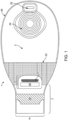
- the medical device or pouch 1 is formed from a front wall 2 and a rear wall 3.
- the front wall of the medical device generally faces away from the body, while the rear wall of the medical device or pouch generally faces towards the body.
- the front and rear wall may comprise at least two separate pieces of material joined together at the edges by adhesive or welding, or may be a single contiguous piece of material.
- the walls may be constructed of a suitable moisture impermeable material.
- the walls may be made of transparent or translucent material.
- the transparent or translucent walls may further comprise at least one flap that partially or fully covers the front wall.
- the flap can be manipulated to view the contents of the medical device or pouch and/or to assist a user or patient in attaching the device.
- the flap is opened or closed by a user or patient to view the contents of the medical device or pouch, or to assist in manipulation of the device or pouch onto, for example, the stoma of a patient.
- the flap material consists of the same water impermeable material as the front and rear walls.
- the flap material consists of a soft, breathable fabric that reduces irritation or chafing to the skin of a patient.
- the flap material may further be secured in a closed position to mask the contents within the pouch or medical device
- the front wall is made of transparent or translucent material and the rear wall is made of opaque material.
- the front and rear wall may be made of opaque material.
- the walls may be made of opaque material with a transparent window 24 for monitoring the contents of the medical device or pouch, or to assist in attaching the medical device or pouch directly or indirectly onto the patient.
- the transparent window may further comprise a flap that can be opened and closed to view the contents of the device and/or to assist the user or patient in attachment of the medical device or pouch.
- the material comprising the front and rear walls as well as the flap may be a plastic, thermoplastic, polymer or a natural substance.
- the material may be a laminate consisting of a plurality of layers or a single layer.
- Suitable materials include but are not limited to ethylene vinyl acetate (EVA), polyvinylidene chloride (PVDC), or ethylene vinyl alcohol (EVOH).
- the front and rear wall material further comprises an anti-microbial substance or coating, or the material itself has anti-microbial properties.
- Exemplary materials for a coating include, but are not limited to, metals or metal alloys of silver, gold, gallium , titanium, titanium dioxide or copper; organosilanes; and quaternary ammonium compounds such as 3-(Trimethoxysilyl) -propyldimethyloctadecyl ammonium chloride (Si-QAC).
- the front and rear wall material for the construction of the device walls provides controls for unpleasant odor.
- the medical device or pouch further comprises a deodorizing filter and vent 22 for deodorizing and venting flatus.
- the filter is a strip filter or an axial filter.
- the strip filter or axial flow filter is wrapped with an odor barrier film around its perimeter.
- the filter has a low profile.
- an open cell foam is added as a pre-filter to prevent solid components from entering into and fouling the filter.
- the filter contains activated carbon.
- the medical device or pouch includes a first comfort layer covering at least part of the rear wall 3 and a second comfort layer covering at least part of the front wall 2.
- the front wall 2 is made of a transparent material
- a comfort layer does not cover the front wall 2.
- the rear wall 3 is made of an opaque material, it is covered, at least partially, by a comfort layer.
- the comfort layer is partially sealed to the front or rear wall that it covers so as to leave an access opening between the comfort layer(s) and the wall it is covering.
- the access opening is perpendicular to the longitudinal axis 27 of the medical device or pouch and proximate to where the walls taper to the outlet 7.
- Exemplary materials for the comfort layer include, but are not limited to, film, foam, woven or non-woven fabric.
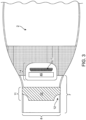
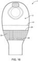
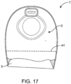
- the device contains a pocket 23 ( Fig. 16 ).
- the outlet 7, in the closed condition can be further folded and tucked into pocket 23 to allow for further security in the closure.
- the pocket 23 is attached to the front wall 2 of the device.
- the pocket 23 is attached to front wall 2 along the periphery of the pouch and has a top edge 25 and a bottom edge 26.
- the top edge 25 of pocket 23 is positioned below the horizontal centerline 41 of pouch 1.
- the top edge 25 of pocket 23 is positioned at the horizontal centerline 41 of pouch 1.
- the top edge 25 of pocket 23 is positioned above the horizontal centerline 41 of pouch 1.
- pocket 23 is made of the same material as that of at least one of the walls. In some embodiments, pocket 23 is made of a different material than that of the walls. Exemplary materials for the pocket include, but are not limited to, film, foam, woven or non-woven fabric.
- the rear wall 3 of the medical device or pouch ( Fig. 2 ) contains an opening comprising a stomal aperture 4 to allow connection to a stoma or peristomal area.
- the stomal aperture further connects to an adhesive wafer or gasket 5, which is attached to or around the stoma or peristomal area.
- the adhesive wafer contains a skin compatible adhesive or sealant for attaching the device to the peristomal skin.
- the adhesive or sealant is moldable.
- the adhesive wafer is removable from the device so that it might be positioned by the user around a stoma before the medical device or pouch is attached. In other embodiments, the adhesive wafer is attached to the medical device or pouch.
- the adhesive wafer 5 and/or stomal aperture 4 further comprise exemplary marks or indications 6 that allow the user to adjust the size of the aperture.
- the rear wall 3 may additionally comprise a coating or additional layer of material to enhance the comfort or breathability of the medical device or pouch when worn by a patient.
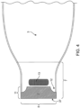
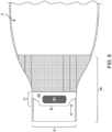
- the medical device or pouch further tapers to an outlet 7 ( Figs. 1 and 2 ) with an outlet opening 8.
- the outlet opening 8 is at the proximal end of the device.
- the outlet opening 8 may extend the entire width of the outlet.
- the opening may extend only partially the width of the outlet.
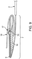
- the outlet is foldable from an open ( Figs. 3 and 4 ) to a closed condition ( Figs. 7 and 9 ).
- the outlet requires a single lateral fold.
- the outlet requires at least two lateral folds to be in a closed condition.
- the outlet requires two lateral folds to be in a closed condition.
- the outlet requires three lateral folds to be in a closed condition.
- the outlet requires four lateral folds to be in a closed condition. In certain embodiments, the outlet requires five lateral folds to be in a closed condition. In some embodiments, the lateral fold results in folding of the outlet in an upward direction away from the opening.
- the first reinforcing member is positioned above the second reinforcing member by a single lateral fold of the outlet. In some embodiments, the first reinforcing member is stacked on top of the second reinforcing member and the first fastener is stacked on top of the first reinforcing member by two lateral folds of the outlet. In some embodiments, the first fastener forms a linkage with the second fastener by three lateral folds of the outlet.
- the outlet has an opening system with at least a first reinforcing member 9 ( Fig. 4 ) and a second ( Fig. 3 ) reinforcing member 10, each of which is attached to an exterior surface of the device on the outlet 7.
- the first reinforcing member and the second reinforcing member are made of the same material. In some embodiments, the first reinforcing member and the second reinforcing member are made of different materials. In some embodiments, the first reinforcing member and the second reinforcing member are each independently made of a resiliently flexible, easily distensible plastic material. In some embodiments, the resiliently flexible easily distensible plastic material is not compressible. Non-limiting examples of resiliently flexible, easily distensible plastic material include polystyrene, polyethylene, polyurethane, polyester, polycarbonate. In preferred embodiments, the first and second reinforcing members are each made of polystyrene. In some embodiments, the first reinforcing member and the second reinforcing member are each independently made of a resiliently flexible metal sheet.
- the first and second reinforcing members are attached to opposing exterior surfaces on the walls.
- the horizontal centerlines of the first and second reinforcing members may be offset with respect to each other as shown in Figs. 8 and 18 .
- the offset of the first and second reinforcing members may enable easy folding and handling of the medical device, for draining and closing. For example, users with poor dexterity may also benefit from the easy folding allowed by the offset of the first and second reinforcing members.
- the first and second reinforcing members may be vertically offset relative to each other, i.e., the vertical centerlines of the first and second reinforcing members may be offset relative to each other.
- the vertical centerline may be a line running along the axis 27 which extends from the proximal end to the distal end of the device.
- the horizontal centerline may be a line running along the axis 28 which runs perpendicular to the axis 27.
- the horizontal and vertical centerlines of the first and second reinforcing members may be offset relative to each other.
- the horizontal centerlines of the first and second reinforcing members may be offset relative to each other by about 0, 1, 2, 3, 4, 5, 6, 7, 8, 9, 10, 11, 12, 13, 14, 15, 16, 17, 18, 19, 20, 21, 22, 23, 24, 25, 26, 27, 28, 29, 30 mm or more.
- the vertical centerlines of the first and second reinforcing members may preferably be offset relative to each other by about 0, 1, 2, 3, 4, 5, 6, 7, 8, 9 or 10 mm or more. More preferably, the horizontal and/or vertical centerlines of the first and second reinforcing members may be offset relative to each other by about 0, 1, 2, 3, 4, 5, 6, 7, 8, 9, 10 mm or more. Most preferably, the horizontal and/or vertical centerlines of the first and second reinforcing members may be offset relative to each other by about 0, 1, 2, 3, 4, 5 mm or more. In some embodiments, the horizontal centerlines of the first and second reinforcing members are offset relative to each other by about 1-5 mm.
- the horizontal centerlines of the first and second reinforcing members are offset relative to each other by about 1-10 mm. In some embodiments, the horizontal centerlines of the first and second reinforcing members are offset relative to each other by about 1-20 mm. In some embodiments, the horizontal centerlines of the first and second reinforcing members are offset relative to each other by about 1-30 mm. In some embodiments, the horizontal centerlines of the first and second reinforcing members are offset relative to each other by about 5-10 mm. In some embodiments, the horizontal centerlines of the first and second reinforcing members are offset relative to each other by about 5-20 mm. In some embodiments, the horizontal centerlines of the first and second reinforcing members are offset relative to each other by about 5-30 mm.
- the horizontal centerlines of the first and second reinforcing members are offset relative to each other by about 10-20 mm. In some embodiments, the horizontal centerlines of the first and second reinforcing members are offset relative to each other by about 10-30 mm. In some embodiments, the horizontal centerlines of the first and second reinforcing members are offset relative to each other by about 20-30 mm. The horizontal centerlines of the first and second reinforcing members may not be offset with respect to each other, but positioned at equal distances from the edge of the outlet opening.
- the first and second reinforcing members may be offset relative to each other, along a longitudinal axis by about 0, 1, 2, 3, 4, 5, 6, 7, 8, 9, 10, 11, 12, 13, 14, 15, 16, 17, 18, 19, 20, 21, 22, 23, 24, 25, 26, 27, 28, 29, 30 mm or more. In some embodiments, the first and second reinforcing members may be offset relative to each other, along a longitudinal axis by about 1-5 mm. In some embodiments, the first and second reinforcing members may be offset relative to each other, along a longitudinal axis by about 1-10 mm. In some embodiments, the first and second reinforcing members may be offset relative to each other, along a longitudinal axis by about 1-20 mm.
- the first and second reinforcing members may be offset relative to each other, along a longitudinal axis by about 1-30 mm. In some embodiments, the first and second reinforcing members may be offset relative to each other, along a longitudinal axis by about 5-10 mm. In some embodiments, the first and second reinforcing members may be offset relative to each other, along a longitudinal axis by about 5-20 mm. In some embodiments, the first and second reinforcing members may be offset relative to each other, along a longitudinal axis by about 5-30 mm. In some embodiments, the first and second reinforcing members may be offset relative to each other, along a longitudinal axis by about 10-20 mm.
- first and second reinforcing members may be offset relative to each other, along a longitudinal axis by about 10-30 mm. In some embodiments, the first and second reinforcing members may be offset relative to each other, along a longitudinal axis by about 20-30 mm.
- the vertical centerlines of the first and second reinforcing members are offset relative to each other by about 1-5 mm. In some embodiments, the vertical centerlines of the first and second reinforcing members are offset relative to each other by about 1-10 mm. In some embodiments, the vertical centerlines of the first and second reinforcing members are offset relative to each other by about 1-20 mm. In some embodiments, the vertical centerlines of the first and second reinforcing members are offset relative to each other by about 1-30 mm. In some embodiments, the vertical centerlines of the first and second reinforcing members are offset relative to each other by about 5-10 mm. In some embodiments, the vertical centerlines of the first and second reinforcing members are offset relative to each other by about 5-20 mm.
- the vertical centerlines of the first and second reinforcing members are offset relative to each other by about 5-30 mm. In some embodiments, the vertical centerlines of the first and second reinforcing members are offset relative to each other by about 10-20 mm. In some embodiments, the vertical centerlines of the first and second reinforcing members are offset relative to each other by about 10-30 mm. In some embodiments, the vertical centerlines of the first and second reinforcing members are offset relative to each other by about 20-30 mm.
- a second reinforcing member 10 is distal to the opening 8 with respect to the first reinforcing member 9.
- the first reinforcing member 9 is immediately adjacent to the opening or its bottom edge 37 is offset from the opening by about 1, 2, 3, 4, 5, 6, 7, 8, 9, 10, 11, 12, 13, 14, 15, 16, 17, 18, 19, 20 mm or more.
- the bottom edge 37 of the first reinforcing member 9 is offset from the opening by about 1 mm. In some embodiments, the bottom edge 37 of the first reinforcing member 9 is offset from the opening by about 2 mm.
- the bottom edge 37 of the first reinforcing member 9 is offset from the opening by about 3 mm. In some embodiments, the bottom edge 37 of the first reinforcing member 9 is offset from the opening by about 4 mm. In some embodiments, the bottom edge 37 of the first reinforcing member 9 is offset from the opening by about 5 mm. In some embodiments, the bottom edge 37 of the first reinforcing member 9 is offset from the opening by about 6 mm. In some embodiments, the bottom edge 37 of the first reinforcing member 9 is offset from the opening by about 7 mm. In some embodiments, the bottom edge 37 of the first reinforcing member 9 is offset from the opening by about 8 mm.
- the bottom edge 37 of the first reinforcing member 9 is offset from the opening by about 9 mm. In some embodiments, the bottom edge 37 of the first reinforcing member 9 is offset from the opening by about 10 mm. In some embodiments, the bottom edge 37 of the first reinforcing member 9 is offset from the opening by more than about 10 mm. In some embodiments, the bottom edge 37 of the first reinforcing member 9 is offset from the opening by about 1-5 mm. In some embodiments, the bottom edge 37 of the first reinforcing member 9 is offset from the opening by about 1-10 mm. In some embodiments, the bottom edge 37 of the first reinforcing member 9 is offset from the opening by about 1-15 mm.
- the bottom edge 37 of the first reinforcing member 9 is offset from the opening by about 1-20 mm. In some embodiments, the bottom edge 37 of the first reinforcing member 9 is offset from the opening by about 3-10 mm. In some embodiments, the bottom edge 37 of the first reinforcing member 9 is offset from the opening by about 3-15 mm. In some embodiments, the bottom edge 37 of the first reinforcing member 9 is offset from the opening by about 3-20 mm. In some embodiments, the bottom edge 37 of the first reinforcing member 9 is offset from the opening by about 5-10 mm. In some embodiments, the bottom edge 37 of the first reinforcing member 9 is offset from the opening by about 5-15 mm.
- the bottom edge 37 of the first reinforcing member 9 is offset from the opening by about 5-20 mm. In some embodiments, the bottom edge 37 of the first reinforcing member 9 is offset from the opening by about 10-15 mm. In some embodiments, the bottom edge 37 of the first reinforcing member 9 is offset from the opening by about 10-20 mm.
- the length of the first reinforcing member 9 extends essentially the entire width of the opening 8. In some embodiments, the length of the second reinforcing member 10 extends essentially the entire width of the opening 8. In some embodiments, lengths of both the first reinforcing member 9 and the second reinforcing member 10 extend essentially the entire width of the opening 8. In some embodiments, the length of the first reinforcing member 9 extends essentially across the entire width of the opening 8 and the length of the second reinforcing member 10 extends essentially only partially across the width of the opening 8. In preferred embodiments, the length of the first reinforcing member 9 extends essentially the entire width of the opening 8. In preferred embodiments, the length of the second reinforcing member 10 extends essentially only partially across the width of the opening 8.
- both the first reinforcing member 9 and the second reinforcing member 10 are about of the same length.
- the first reinforcing member 9 is about 5, 10, 15, 20, 25, 30, 35, 40, 45, 50, 55 mm, 60 mm, 65 mm, 70 mm, 75 mm, 80 mm, 85 mm, or any increment thereof, long.
- the first reinforcing member 9 is about 5-85 mm long.
- the first reinforcing member 9 is about 5-80 mm long.
- the first reinforcing member 9 is about 5-40 mm long.
- the first reinforcing member 9 is about 5-70 mm long.
- the first reinforcing member 9 is about 5-60 mm long. In some embodiments, the first reinforcing member 9 is about 5-55 mm long. In some embodiments, the first reinforcing member 9 is about 5-50 mm long. In some embodiments, the first reinforcing member 9 is about 5-40 mm long. In some embodiments, the first reinforcing member 9 is about 5-30 mm long. In some embodiments, the first reinforcing member 9 is about 5-20 mm long. In some embodiments, the first reinforcing member 9 is about 5-10 mm long. In some embodiments, the first reinforcing member 9 is about 75-80 mm long.
- the second reinforcing member 10 is about 5, 10, 15, 20, 25, 30, 35, 40, 45, 50, 55 mm, 60 mm, 65 mm, 70 mm, 75 mm, 80 mm, 85 mm, or any increment thereof, long. In some embodiments, the second reinforcing member 10 is about 5-85 mm long. In some embodiments, the second reinforcing member 10 is about 5-80 mm long. In some embodiments, the second reinforcing member 10 is about 5-40 mm long. In some embodiments, the second reinforcing member 10 is about 5-70 mm long. In some embodiments, the second reinforcing member 10 is about 5-60 mm long. In some embodiments, the second reinforcing member 10 is about 5-50 mm long.
- the second reinforcing member 10 is about 5-40 mm long. In some embodiments, the second reinforcing member 10 is about 5-40 mm long. In some embodiments, the second reinforcing member 10 is about 5-30 mm long. In some embodiments, the second reinforcing member 9 is about 5-20 mm long. In some embodiments, the second reinforcing member 10 is about 5-10 mm long. In some embodiments, the second reinforcing member 10 is about 75-80 mm long.
- the lengths of the first (9) and second (10) reinforcing members are correlated with preventing incidences of leak from the medical device disclosed herein when it is in a closed condition.
- the probability of an incidence of leak is about 10% to about 25% less in a medical device where first (9) and second (10) reinforcing members are 80 mm long than in a medical device where the first (9) and second (10) reinforcing members are 50 mm long.
- the first reinforcing member 9 is about 2, 3, 4, 5, 6, 7, 8, 9, 10, 11, 12, 13, 14, 15, 16, 17, 18, 19, or 20 mm wide. In some embodiments, the first reinforcing member 9 is about 2-20 mm wide. In some embodiments, the first reinforcing member 9 is about 5-20 mm wide. In some embodiments, the first reinforcing member 9 is about 10-20 mm wide. In some embodiments, the second reinforcing member 10 is about 2, 3, 4, 5, 6, 7, 8, 9, 10, 11, 12, 13, 14, 15, 16, 17, 18, 19, or 20 mm wide. In some embodiments, the second reinforcing member 10 is about 2-20 mm wide. In some embodiments, the second reinforcing member 10 is about 5-20 mm wide.
- the second reinforcing member 10 is about 10-20 mm wide. In some embodiments, the first reinforcing member 9 and the second reinforcing member 10 are offset from each other, along the vertical axis 28, by about 1 mm to about 5 mm. In some embodiments, the widths of the first 9 and second 10 reinforcing members are dependent on the type of material used for the reinforcing members. In some embodiments, the widths of the first 9 and second 10 reinforcing members are proportional to their flexibility. In some embodiments, the first reinforcing member 9 and the second reinforcing member 10 are made of polystyrene and are about 20 mm wide.
- first reinforcing member 9 and the second reinforcing member 10 are made of polyethylene and are about 15 mm wide. In preferred embodiments, the first reinforcing member 9 and the second reinforcing member 10 are made of polystyrene.
- the first reinforcing member 9 and the second reinforcing member 10 have lateral edges 11 .
- the lateral edges are deformable by application of pressure.
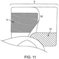
- Fig. 11 is a sideview of the outlet in use illustrating the application of pressure to the first reinforcing member 9 and the second reinforcing member 10, of the first embodiment, as the opening 8 is radially distended and opened for drainage. A user squeezes together the lateral edges of reinforcing member 9 and reinforcing 10 at the peripheral edge of the outlet 33.
- the reinforcing member While reinforcing member 9 is placed away from edge of the opening 8 in this view, the reinforcing member may be at or near the opening edge 8, for example, at a distance of about 0, 1, 2, 3, 4, 5, 6, 7, 8, 9, 10, 11, 12, 13, 14, 15, 16, 17, 18, 19, 20 mm or more from the opening edge 8.
- pressure may be applied to the lateral edges of the first reinforcing member 9 and the second reinforcing member 10 to push the edges from its flat un-deformed state to a curved deformed state inward towards the midline of the opening 8, thereby radially distending the opening 8. Such deformation is reversible when the pressure is removed.
- the first reinforcing member 9 and the second reinforcing member 10 have corners that are notched, grooved, cut-to-shape or the like.
- the first reinforcing member 9 and the second reinforcing member 10 may have corners that are square, rounded, flared, or have material removed, creating a void 12 ( Figs. 3 and 4 ) to facilitate finger positioning by a user.
- the material can be removed from either a single lateral edge or from both lateral edges.
- the shape of the first and second reinforcing members may enable easy handling of the medical device, for draining and closing.
- a user may have his/her fingers fit the notched or voided region of the first and second reinforcing member, to open or close the outlet with ease. Further, users with poor dexterity may also benefit from the notched or voided design of the first and second reinforcing members.
- the reinforcing member may have corners that are grooved, cut-to-shape or the like to allow finger positioning by a user.
- the first reinforcing member 9 may be positioned above to the second reinforcing member 10 by a single lateral fold of the outlet. In some embodiments, the first reinforcing member 9 may be stacked on top of the second reinforcing member 10 and the first fastener 13 may be stacked on top of the first reinforcing member by two lateral folds of the outlet. In some embodiments, the first fastener 13 may form a linkage with the second fastener 17 by three lateral folds of the outlet, as seen in Fig. 9 .
- the bottom edge 38 of the first reinforcing member 29 is distal to the opening 8, with respect to the second reinforcing member 30.
- the bottom edge 38 of the second reinforcing member 30 is immediately adjacent to the opening or its bottom edge 38 is offset from the opening by about 1, 2, 3, 4, 5, 6, 7, 8, 9, 10 mm or more.
- the bottom edge 38 of the second reinforcing member 30 is offset from the opening by about 1, 2, 3, 4, 5, 6, 7, 8, 9, 10, 11, 12, 13, 14, 15, 16, 17, 18, 19, 20 mm or more.
- the bottom edge 38 of the second reinforcing member 30 is offset from the opening by about 1 mm. In some embodiments, the bottom edge 38 of the second reinforcing member 30 is offset from the opening by about 2 mm. In some embodiments, the bottom edge 38 of the second reinforcing member 30 is offset from the opening by about 3 mm. In some embodiments, the bottom edge 38 of the second reinforcing member 30 is offset from the opening by about 4 mm. In some embodiments, the bottom edge 38 of the second reinforcing member 30 is offset from the opening by about 5 mm. In some embodiments, the bottom edge 38 of the second reinforcing member 30 is offset from the opening by about 6 mm.
- the bottom edge 38 of the second reinforcing member 30 is offset from the opening by about 7 mm. In some embodiments, the bottom edge 38 of the second reinforcing member 30 is offset from the opening by about 8 mm. In some embodiments, the bottom edge 38 of the second reinforcing member 30 is offset from the opening by about 9 mm. In some embodiments, the bottom edge 38 of the second reinforcing member 30 is offset from the opening by about 10 mm. In some embodiments, the bottom edge 38 of the second reinforcing member 30 is offset from the opening by more than about 10 mm. In some embodiments, the bottom edge 38 of the second reinforcing member 30 is offset from the opening by about 1-5 mm.
- the bottom edge 38 of the second reinforcing member 30 is offset from the opening by about 1-10 mm. In some embodiments, the bottom edge 38 of the second reinforcing member 30 is offset from the opening by about 1-15 mm. In some embodiments, the bottom edge 38 of the second reinforcing member 30 is offset from the opening by about 1-20 mm. In some embodiments, the bottom edge 38 of the second reinforcing member 30 is offset from the opening by about 3-10 mm. In some embodiments, the bottom edge 38 of the second reinforcing member 30 is offset from the opening by about 3-15 mm. In some embodiments, the bottom edge 38 of the second reinforcing member 30 is offset from the opening by about 3-20 mm.
- the bottom edge 38 of the second reinforcing member 30 is offset from the opening by about 5-10 mm. In some embodiments, the bottom edge 38 of the second reinforcing member 30 is offset from the opening by about 5-15 mm. In some embodiments, the bottom edge 38 of the second reinforcing member 30 is offset from the opening by about 5-20 mm. In some embodiments, the bottom edge 38 of the second reinforcing member 30 is offset from the opening by about 10-15 mm. In some embodiments, the bottom edge 38 of the second reinforcing member 30 is offset from the opening by about 10-20 mm.
- the length of the first reinforcing member 29 essentially extends the entire width of the opening 8. In some embodiments, the length of the second reinforcing member 30 essentially extends the entire width of the opening 8. In some embodiments, lengths of both the first reinforcing member 29 and the second reinforcing member 30 essentially extend the entire width of the opening 8. In some embodiments, the length of the first reinforcing member 29 essentially extends across the entire width of the opening 8 and the length of the second reinforcing member 30 essentially extends only partially across the width of the opening 8. In preferred embodiments, the length of the first reinforcing member 29 essentially extends the entire width of the opening 8. In preferred embodiments, the length of the second reinforcing member 30 essentially extends only partially across the width of the opening 8.
- both the first reinforcing member 29 and the second reinforcing member 30 are the same length.
- the first reinforcing member 29 is about 5, 10, 15, 20, 25, 30, 35, 40, 45, 50, 55 mm, 60 mm, 65 mm, 70 mm, 75 mm, 80 mm, 85 mm, or any increment thereof, long.
- the first reinforcing member 29 is about 5-55 mm long.
- the first reinforcing member 29 is about 5-85 mm long.
- the first reinforcing member 29 is about 5-80mm long.
- the first reinforcing member 29 is about 5-70 mm long.
- the first reinforcing member 29 is about 5-60 mm long. In some embodiments, the first reinforcing member 29 is about 5-50 mm long. In some embodiments, the first reinforcing member 29 is about 5-40 mm long. In some embodiments, the first reinforcing member 29 is about 5-40 mm long. In some embodiments, the first reinforcing member 29 is about 5-30 mm long. In some embodiments, the first reinforcing member 29 is about 5-20 mm long. In some embodiments, the first reinforcing member 29 is about 5-10 mm long. In some embodiments, the first reinforcing member 29 is about 75-80 mm long.
- the second reinforcing member 30 is about 5, 10, 15, 20, 25, 30, 35, 40, 45, 50, 55 mm, 60 mm, 65 mm, 70 mm, 75 mm, 80 mm, 85 mm, or any increment thereof, long. In some embodiments, the second reinforcing member 30 is about 5-85 mm long. In some embodiments, the second reinforcing member 30 is about 5-80 mm long. In some embodiments, the second reinforcing member 30 is about 5-70 mm long. In some embodiments, the second reinforcing member 30 is about 5-60 mm long. In some embodiments, the second reinforcing member 30 is about 5-50 mm long. In some embodiments, the second reinforcing member 30 is about 5-40 mm long.
- the second reinforcing member 30 is about 5-40 mm long. In some embodiments, the second reinforcing member 30 is about 5-30 mm long. In some embodiments, the second reinforcing member 30 is about 5-20 mm long. In some embodiments, the second reinforcing member 30 is about 5-10 mm long. In some embodiments, the second reinforcing member 30 is about 75-80 mm long.
- the lengths of the first (29) and second (30) reinforcing members are correlated with preventing incidences of leak from the medical device disclosed herein when it is in a closed condition.
- the probability of an incidence of leak is about 10% to about 25% less in a medical device where first (29) and second (30) reinforcing members are 80 mm long than in a medical device where the first (29) and second (30) reinforcing members are 50 mm long.
- the first reinforcing member 29 is about 2, 3, 4, 5, 6, 7, 8, 9, 10, 11, 12, 13, 14, 15, 16, 17, 18, 19, or 20 mm wide. In some embodiments, the first reinforcing member 29 is about 2-20 mm wide. In some embodiments, the first reinforcing member 29 is about 5-20 mm wide. In some embodiments, the first reinforcing member 29 is about 10-20 mm wide. In some embodiments, the second reinforcing member 30 is about 2, 3, 4, 5, 6, 7, 8, 9, 10, 11, 12, 13, 14, 15, 16, 17, 18, 19, or 20 mm wide. In some embodiments, the second reinforcing member 30 is about 2-20 mm wide. In some embodiments, the second reinforcing member 30 is about 5-20 mm wide. In some embodiments, the second reinforcing member 10 is about 10-20 mm wide.
- the widths of the first 29 and second 30 reinforcing members are dependent on the type of material used for the reinforcing members. In some embodiments, the widths of the first 29 and second 30 reinforcing members are proportional to their flexibility. In some embodiments, the first reinforcing member 29 and the second reinforcing member 30 are made of polystyrene and are about 20 mm wide. In some embodiments, the first reinforcing member 29 and the second reinforcing member 30 are made of polyethylene and are about 15 mm wide. In preferred embodiments, the first reinforcing member 29 and the second reinforcing member 30 are made of polystyrene.
- the first reinforcing member 29 and the second reinforcing member 30 have lateral edges 11.
- the lateral edges are deformable by application of pressure.
- the first reinforcing member 29 and the second reinforcing member 30 have corners that are notched, square, rounded, flared, or have material removed, creating a void 12 ( Figs. 5 and 6 ), to facilitate finger positioning by a user.
- the material removed can be wedge shaped 12 ( Figs. 5 and 6 ) or triangular 32 ( Fig. 10 ).
- the material can be removed from either a single lateral edge or from both lateral edges.
- the reinforcing member may have corners that are grooved, cut-to-shape or the like to allow finger positioning by a user.
- the first or second embodiment of the medical device with an opening system may further comprise a securing system for securing the opening in the closed condition.
- the securing system has a first fastener 13, attached to an exterior wall of the medical device or pouch; and a security flap 14.
- the first fastener 13 and the security flap 14 may be attached to opposing walls of the medical device or pouch 1.
- the security flap 14 is attached to the front wall 2 and the first fastener 13 is directly attached to the rear wall 3, as shown in Figs. 3 and 4 , respectively.
- the bottom edge of the first fastener 13 is immediately adjacent to or offset relative to the top edge of the first reinforcing member 9.
- the bottom edge of the first fastener 13 is immediately adjacent to the top edge of the first reinforcing member 9. In these embodiments, the bottom edge of the first fastener 13 is offset relative to the top edge of the first reinforcing member 9 by about 1, 2, 3, 4, 5, 6, 7, 8, 9, 10, 11, 12, 13, 14, 15, 16, 17, 18, 19, 20, 25, 30, 35, 40, 45, 50 mm or more, or any increment thereof. In these embodiments, the bottom edge of the first fastener 13 is offset relative to the top edge of the first reinforcing member 9 by about 1-100 mm. In these embodiments, the bottom edge of the first fastener 13 is offset relative to the top edge of the first reinforcing member 9 by about 1-50 mm.
- the bottom edge of the first fastener 13 is offset relative to the top edge of the first reinforcing member 9 by about 1-20 mm. In these embodiments, the bottom edge of the first fastener 13 is offset relative to the top edge of the first reinforcing member 9 by about 1-10 mm.
- the security flap 14 is attached to the front wall 2 and the first fastener 13 is attached to the first reinforcing member 29 located on the rear wall 3, as shown in Figs. 5 and 6 , respectively. As illustrated in the first embodiment shown in Fig.
- the security flap 14 comprises a first portion 15 attached to one of the opposing walls of the medical device or pouch, on the outlet 7, and a second portion 16 freely extended outward from the same opposing wall of the medical device or pouch 1, on the outlet 7.
- the security flap 14 may be provided on the front wall 2 of the medical device or pouch 1, as shown in Figs. 3 , 5 and 8 .
- the security flap 14 may be fastened to the front wall 2, for example by welding or by adhesive, or it may be an extension of a layer or portion forming the front wall 2.
- the freely extended portion 16 of security flap 14 is configured to be folded over the outlet 7 when the outlet is in the closed condition.
- the securing system may further comprise a second fastener 17, wherein the second fastener is attached to the freely extended portion 16 of the security flap, as shown in Fig. 8 .
- the freely extended portion 16 of the security flap 14 is folded over the outlet 7 when the outlet is in the closed condition, and secured by the formation of a linkage between the first fastener 13 and second fastener 17.
- the first fastener 13 and the second fastener 17 are able to form a linkage after at least two lateral folds as shown in Figs. 7 and 9 .
- the freely extended portion 16 of the security flap 14 is folded over the outlet 7 when the outlet is in the closed condition, by forming a linkage between the first fastener 13 and second fastener 17 (not shown).
- the first fastener 13 on the rear wall 3 may be approximately in register with the second reinforcing member 10 on the front wall 2.
- the security flap 14 prevents the outlet 7 from dropping down to its draining position (i.e ., opened condition) while the security flap 14 is in its fastened condition.
- the security flap comprises a semi-rigid or elasticized material capable of maintaining its shape after repeated closure.
- the security flap comprises a memory foam-like material.
- the security flap comprises film.
- the security flap comprises a fabric.
- the fabric is a woven fabric or a non-woven fabric.
- the first and second fasteners may be hook-and-loop fasteners, hook-and-pile fasteners, touch fasteners, adhesive couplings, molded couplings, formed couplings, snap closures, or hook and hook fasteners.
- Velcro TM is an exemplary hook and loop fastener.
- the first and second fasteners are hook-and-loop fasteners.
- the first and second fasteners are hook-and-pile fasteners.
- the first and second fasteners are touch fasteners.
- the first and second fasteners are adhesive couplings.
- the first and second fasteners are molded couplings.
- the first and second fasteners are formed couplings. In some embodiments, the first and second fasteners are snap closures. In some embodiments, the first and second fasteners are hook and hook fasteners. In certain embodiments, any of the fasteners re fixed directly to the pouch. In certain embodiments, any of the fasteners are fixed to one of the reinforcing members. In certain embodiments, the any of the fasteners itself serves as a reinforcing member.
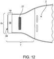
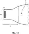
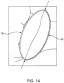
- Figs. 12 , 13 and 14 are exemplary of a third embodiment of a medical device with an opening system not in accordance with the present invention.
- This embodiment has a single reinforcing member 18 attached to an exterior surface of the device near the opening 8.
- the single reinforcing member 18 may be immediately adjacent to the opening, as shown in Fig. 12 .
- the bottom edge 39 of the single reinforcing member 18 may be offset from the opening by about 1, 2, 3, 4, 5, 6, 7, 8, 9, 10, 11, 12, 13, 14, 15, 16, 17, 18, 19, 20 mm or more.
- the bottom edge 39 of the single reinforcing member 18 is offset from the opening by about 1 mm.
- the bottom edge 39 of the single reinforcing member 18 is offset from the opening by about 2 mm. In some embodiments, the bottom edge 39 of the single reinforcing member 18 is offset from the opening by about 3 mm. In some embodiments, the bottom edge 39 of the single reinforcing member 18 is offset from the opening by about 4 mm. In some embodiments, the bottom edge 39 of the single reinforcing member 18 is offset from the opening by about 5 mm. In some embodiments, the bottom edge 39 of the single reinforcing member 18 is offset from the opening by about 6 mm. In some embodiments, the bottom edge 39 of the single reinforcing member 18 is offset from the opening by about 7 mm.
- the bottom edge 39 of the single reinforcing member 18 is offset from the opening by about 8 mm. In some embodiments, the bottom edge 39 of the single reinforcing member 18 is offset from the opening by about 9 mm. In some embodiments, the bottom edge 39 of the single reinforcing member 18 is offset from the opening by about 10 mm. In some embodiments, the bottom edge 39 of the single reinforcing member 18 is offset from the opening by more than about 10 mm. In some embodiments, the bottom edge 39 of the single reinforcing member 18 is offset from the opening by about 1-5 mm. In some embodiments, the bottom edge 39 of the single reinforcing member 18 is offset from the opening by about 1-10 mm.
- the bottom edge 39 of the single reinforcing member 18 is offset from the opening by about 1-15 mm. In some embodiments, the bottom edge 39 of the single reinforcing member 18 is offset from the opening by about 1-20 mm. In some embodiments, the bottom edge 39 of the single reinforcing member 18 is offset from the opening by about 3-10 mm. In some embodiments, the bottom edge 39 of the single reinforcing member 18 is offset from the opening by about 3-15 mm. In some embodiments, the bottom edge 39 of the single reinforcing member 18 is offset from the opening by about 3-20 mm. In some embodiments, the bottom edge 39 of the single reinforcing member 18 is offset from the opening by about 5-10 mm.
- the bottom edge 39 of the single reinforcing member 18 is offset from the opening by about 5-15 mm. In some embodiments, the bottom edge 39 of the single reinforcing member 18 is offset from the opening by about 5-20 mm. In some embodiments, the bottom edge 39 of the single reinforcing member 18 is offset from the opening by about 10-15 mm. In some embodiments, the bottom edge 39 of the single reinforcing member 18 is offset from the opening by about 10-20 mm.
- the single reinforcing member 18 essentially extends the entire width of the opening 8. In other embodiments, the single reinforcing member 18 essentially extends only partially across the width of the opening 8. In some embodiments, the single reinforcing member 18 is about 5, 10, 15, 20, 25, 30, 35, 40, 45, 50, 55 mm, 60 mm, 65 mm, 70 mm, 75 mm, 80 mm, or 85 mm, or any increment thereof, long. In some embodiments, the single reinforcing member 18 is about 5-85 mm long. In some embodiments, the single reinforcing member 18 is about 5-80 mm long. In some embodiments, the single reinforcing member 18 is about 5-60 mm long.
- the single reinforcing member 18 is about 5-70 mm long. In some embodiments, the single reinforcing member 18 is about 5-50 mm long. In some embodiments, the single reinforcing member 18 is about 5-40 mm long. In some embodiments, the single reinforcing member 18 is about 5-25 mm long. In some embodiments, the single reinforcing member 18 is about 5-30 mm long. In some embodiments, the single reinforcing member 18 is about 5-20 mm long. In some embodiments, the single reinforcing member 18 is about 5-10 mm long. In some embodiments, the single reinforcing member 18 is about 75-80 mm long.
- the single reinforcing member 18 has lateral edges 19.
- the reinforcing member 18 is deformable by the application of manual pressure to its lateral edges, optionally in the direction of the arrows from its flat un-deformed state to a curved deformed state as shown in Fig. 14 .
- the outlet opening distends radially under the pressure. Such deformation is reversible when the pressure is removed.
- the reinforcing member has corners that are notched, square, rounded, flared or have material removed, creating a void, to facilitate finger positioning by a user.
- the material removed can be wedge shaped or triangular.
- the reinforcing member may have corners that are grooved, cut-to-shape or the like to allow finger positioning by a user.
- the third embodiment of the medical device with an opening system may further comprise a first fastener 20 and a second fastener 21, attached to opposing exterior surfaces on the walls, as shown in Figs. 12 and 13 .
- the first fastener 20 may be opposite the single reinforcing member 18.
- the horizontal and/or vertical centerlines of both the single reinforcing member 18 and the first fastener 20 are aligned with one another.
- the horizontal and/or vertical centerlines of the single reinforcing member 18 and the first fastener 20 are offset relative to one another by about 0, 1, 2, 3, 4, 5, 6, 7, 8, 9, 10, 11, 12, 13, 14, 15, 16, 17, 18, 19, 20, 21, 22, 23, 24, 25, 26, 27, 28, 29, 30 mm or more.
- the horizontal and/or vertical centerlines of the single reinforcing member 18 and the first fastener 20 may be offset relative to each other by about 0, 1, 2, 3, 4, 5, 6, 7, 8, 9, 10 mm or more.
- the single reinforcing member 18 and the first fastener 20 may be vertically and/or horizontally offset relative to each other by about 0, 1, 2, 3, 4, 5 mm or more.
- the second fastener 21 is opposite the first fastener 20 and distal to the opening 8 with respect to the single reinforcing member 18.
- the horizontal centerline of second fastener 21 is offset relative to the horizontal centerline of the single reinforcing member 18 by about 20, 25, 30, 35, 40, 45, 50, 55, 60, 65, 70, 75, 80, 85, 90, 95, or 100 mm, or increments thereof.
- the horizontal centerline of second fastener 21 is offset relative to the horizontal centerline of the single reinforcing member 18 by about 20-100 mm.
- the horizontal centerline of second fastener 21 is offset relative to the horizontal centerline of the single reinforcing member 18 by about 20-90 mm. In some embodiments, the horizontal centerline of second fastener 21 is offset relative to the horizontal centerline of the single reinforcing member 18 by about 20-80 mm. In some embodiments, the horizontal centerline of second fastener 21 is offset relative to the horizontal centerline of the single reinforcing member 18 by about 20-70 mm. In some embodiments, the horizontal centerline of second fastener 21 is offset relative to the horizontal centerline of the single reinforcing member 18 by about 20-60 mm. In some embodiments, the horizontal centerline of second fastener 21 is offset relative to the horizontal centerline of the single reinforcing member 18 by about 20-50 mm.
- first fastener 20 and the second fastener 21 are hook-and-loop fasteners, hook-and-pile fasteners, or touch fasteners, adhesive coupling, molded couplings, formed couplings, snap closures, or hook and hook fasteners.
- Velcro TM is an exemplary hook and loop fastener.
- the first fastener 20 and the second fastener 21 are hook-and-loop fasteners.
- the first fastener 20 and the second fastener 21 are hook-and-pile fasteners.
- the first fastener 20 and the second fastener 21 are touch fasteners.
- first fastener 20 and the second fastener 21 are adhesive couplings. In some embodiments, the first fastener 20 and the second fastener 21 are molded couplings. In some embodiments, the first fastener 20 and the second fastener 21 are formed couplings. In some embodiments, the first fastener 20 and the second fastener 21 are snap closures. In some embodiments, the first fastener 20 and the second fastener 21 are hook and hook fasteners.
- the first fastener 20 may lie directly on top of, and be attached to, a second reinforcing member (not shown). In this third embodiment, the first fastener 20 and second fastener 21 can form a linkage after at least two lateral folds of the outlet 7.
- the aforementioned third embodiment may also have a securing system
- the securing system consists of a third fastener (not shown) attached to one exterior wall, and a security flap (not shown) attached to an exterior surface of the outlet with one end extending freely, having a fourth fastener.
- the fourth fastener may be able to form a linkage with the third fastener after at least two lateral folds of the outlet.
- the outlet requires a single lateral fold.
- the outlet requires two lateral folds to be in a closed condition.
- the outlet requires three lateral folds to be in a closed condition.
- the outlet requires four lateral folds to be in a closed condition.
- the outlet requires five lateral folds to be in a closed condition.
- the lateral folds are carried out in an upward direction with respect to the opening 8 such that the outlet 7 is folded from an open to a closed condition.
- the third and the fourth fastener form a linkage after three lateral folds of the outlet.
- the third and the fourth fastener form a linkage after four lateral folds of the outlet.
- the third and the fourth fastener form a linkage after five lateral folds of the outlet.
- the medical device with an opening system further comprises one or more support members (not shown), distinct from the reinforcing members in that they do not essentially extend for the entire width of the opening. These supports can aid in the radial distension of the opening (not shown).
- the support members are made of the same material as the reinforcing member.
- the support members are made of a different material than the reinforcing member.
- the support members are about 5, 10, 15, 20, 25, 30, 35, 40, 45, 50, 55 mm, 60 mm, 65 mm, or 70 mm, or any increment thereof, long. In some embodiments, the support members are about 5-70 mm long.
- the support members are about 5-65 mm long. In some embodiments, the support members are about 5-60 mm long. In some embodiments, the support members are about 5-55 mm long. In some embodiments, the support members are about 5-50 mm long. In some embodiments, the support members are about 5-50 mm long. In some embodiments, the support members are about 5-40 mm long. In some embodiments, the support members are about 5-30 mm long. In some embodiments, the support members are about 5-20 mm long. In some embodiments, the support members are about 5-10 mm long.
- the length of the support members is 5-20% less than the length of the reinforcing members. In some embodiments, the length of the support members is about 5% less than the length of the reinforcing members. In some embodiments, the length of the support members is about 10% less than the length of the reinforcing members. In some embodiments, the length of the support members is about 15% less than the length of the reinforcing members. In some embodiments, the length of the support members is about 20% less than the length of the reinforcing members.
- the one or more support members are attached to the front wall 2. In some embodiments, the one or more support members, are positioned between the second reinforcing member 10 and the security flap 14. In some embodiments, the one or more support members are attached to the front wall 2. In some embodiments, the one or more support members, are positioned within the outlet, above the first reinforcing member 9.
- the medical device with an opening system further includes a flap 31 present between the front wall 2 and the rear wall 3, as illustrated in Fig. 15 .
- the flap 31 is welded to the front wall 2.
- the flap 31 has a partially free edge portion that is attached intermittently 34 to the inner surface of the front wall 2 and has openings 35 that permit odorous gas to reach the filter assembly 22 for deodorization while deterring a ballooning of the pouch 1 due to captured gas within the pouch.
- the flap 31 essentially extends partially down from the top edge 36 of the medical device or pouch 1 so as to at least partially and preferably totally cover and protect the filter assembly 22 from any body waste material entering the medical device or pouch 1 through the stomal aperture 4.
- the top edge of the flap 31 is about 5 mm, about 10 mm, about 15 mm, about 20 mm, or about 25 mm, or any increments thereof, below the top edge 36 of the medical device or pouch 1.
- the top edge of the flap 31 is about 5- 25 mm below the top edge 36 of the medical device or pouch 1.
- the top edge of the flap 31 is about 5- 20 mm below the top edge 36 of the medical device or pouch 1.
- the top edge of the flap 31 is about 5-15 mm below the top edge 36 of the medical device or pouch 1. In some embodiments, the top edge of the flap 31 is about 5-10 mm below the top edge 36 of the medical device or pouch 1. In some embodiments, the top edge of the flap 31 is about 15- 20 mm below the top edge 36 of the medical device or pouch 1.
- the partially free edge portion 32 of the flap is welded to the inner wall of the front wall 2 by one or more spot welds. In some embodiments, the partially free edge portion of the flap is welded to the inner wall of the front wall 2 by four spot welds.
- This disclosure also provides for methods of manufacture of the medical device or pouch with an opening system.
- Components can be positioned onto a substrate by hand in a sequential process using fixtures.
- a manual or automated web process can be used in conjunction with automatic dispensing, pick and place or other automatic transport to position the components onto a substrate.
- the components can be attached to the substrate by bonding, sealing or adhesive attachment.
Landscapes
- Health & Medical Sciences (AREA)
- Life Sciences & Earth Sciences (AREA)
- General Health & Medical Sciences (AREA)
- Orthopedic Medicine & Surgery (AREA)
- Engineering & Computer Science (AREA)
- Biomedical Technology (AREA)
- Heart & Thoracic Surgery (AREA)
- Nursing (AREA)
- Vascular Medicine (AREA)
- Animal Behavior & Ethology (AREA)
- Epidemiology (AREA)
- Public Health (AREA)
- Veterinary Medicine (AREA)
- Chemical & Material Sciences (AREA)
- Dispersion Chemistry (AREA)
- Orthopedics, Nursing, And Contraception (AREA)
- Infusion, Injection, And Reservoir Apparatuses (AREA)
Claims (14)
- Ein Stomabeutel (1), aufweisend:a. gegenüberliegende Wände (2, 3) mit einem Hohlraum dazwischen, wobei die Wände entlang ihrer Ränder verbunden sind und sich zu einer Auslassöffnung (8) am proximalen Ende der Vorrichtung verjüngen;b. ein erstes und ein zweites verformbares Verstärkungselement (9, 10, 29, 30), die an gegenüberliegenden Außenflächen der gegenüberliegenden Wände (2, 3) angebracht sind, wobei jedes Verstärkungselement zwei Seitenkanten (11) aufweist, die durch manuelle Anwendung von Druck auf die Seitenkanten verformbar sind, um die Auslassöffnung (8) radial zu erweitern, wobei das erste und das zweite verformbare Verstärkungselement entlang einer Längsachse (27) gegeneinander versetzt angeordnet sind, undc. einen ersten und einen zweiten Verschluss (13, 17); wobei der Auslass (7) flexibel und durch eine oder mehrere Faltungen von einem offenen Zustand in einen geschlossenen Zustand faltbar ist, dadurch gekennzeichnet, dass an den Seitenkanten des ersten und des zweiten Verstärkungselements Material entfernt wurde, um Ecken mit Leerraum (12) zu bilden.
- Stomabeutel nach Anspruch 1, wobei der Leerraum (12) der Seitenkanten der ersten und zweiten verformbaren Verstärkungselemente (9, 10, 29, 30) eine Kerbe bildet.
- Stomabeutel nach Anspruch 1 oder 2, der ferner ein System zur Sicherung der Vorrichtung in dem geschlossenen Zustand aufweist, wobei das System aufweist:
d. eine Sicherheitsklappe (14), wobei die Klappe an der gleichen Außenfläche einer der gegenüberliegenden Wände (2) wie das zweite Verstärkungselement (10, 30) distal zur Öffnung (8) des Auslasses (7) in Bezug auf das zweite Verstärkungselement angebracht ist, wobei sich ein Teil der Klappe (14) frei von der Außenfläche der gegenüberliegenden Wand (2) erstreckt, an der die Klappe angebracht ist; und
wobei der erste Verschluss (13) an der gleichen Außenfläche einer der gegenüberliegenden Wände (3) wie das erste Verstärkungselement (9, 29), distal zur Öffnung (8) in Bezug auf das erste Verstärkungselement, angebracht ist und der zweite Verschluss (17) an dem frei geöffneten Abschnitt der Sicherheitsklappe (14) angebracht ist, wobei der erste Verschluss (13) und der zweite Verschluss (17) in der Lage sind, eine Verbindung zu bilden, wenn sich der Auslass (7) in dem geschlossenen Zustand befindet. - Stomabeutel nach einem der Ansprüche 1 bis 3, wobei wenigstens einer der ersten und zweiten Verschlüsse (13, 17) ein Klettverschluss ist.
- Stomabeutel nach einem der Ansprüche 1 bis 4, wobei sich das erste verformbare Verstärkungselement (9) in der Nähe der Auslassöffnung (8) befindet und das zweite verformbare Verstärkungselement (10) in Bezug auf das erste verformbare Verstärkungselement (9) distal zur Auslassöffnung (8) angeordnet ist.
- Stomabeutel nach einem der Ansprüche 1 bis 4, wobei sich das zweite verformbare Verstärkungselement (30) in der Nähe der Auslassöffnung (8) befindet und das erste verformbare Verstärkungselement (29) in Bezug auf das zweite verformbare Verstärkungselement (30) distal zur Auslassöffnung (8) angeordnet ist.
- Stomabeutel nach einem der Ansprüche 1 bis 6, wobei sich das erste und zweite verformbare Verstärkungselement (9, 10, 29, 30) in ihrer Größe unterscheiden.
- Stomabeutel nach einem der Ansprüche 1 bis 7, wobei sich das erste und zweite verformbare Verstärkungselement (9, 10, 29, 30) in ihrer Form unterscheiden.
- Stomabeutel nach einem der Ansprüche 1 bis 8, wobei sich wenigstens eines der ersten und zweiten verformbaren Verstärkungselemente (9, 10, 29, 30) über die gesamte Breite der Auslassöffnung (8) erstreckt.
- Stomabeutel nach einem der Ansprüche 1 bis 9, wobei sich wenigstens einer der ersten und zweiten Verschlüsse (13, 17) über die gesamte Breite der Auslassöffnung (8) erstreckt.
- Stomabeutel nach einem der Ansprüche 1 bis 10, wobei sich der erste und der zweite Verschluss (13, 17) in ihrer Größe unterscheiden.
- Stomabeutel nach einem der Ansprüche 1 bis 11, wobei sich der erste und der zweite Verschluss (13, 17) in ihrer Form unterscheiden.
- Stomabeutel nach einem der Ansprüche 1 bis 12, wobei der erste und der zweite Verschluss (13, 17) nach zwei lateralen Faltungen des Auslasses (7) eine Verbindung bilden.
- Stomabeutel nach einem der Ansprüche 1 bis 13, der ferner eine Tasche (23) aufweist, wobei der Auslass (7) in dem geschlossenen Zustand ferner faltbar ist, um in der Tasche verstaut zu werden.
Priority Applications (1)
| Application Number | Priority Date | Filing Date | Title |
|---|---|---|---|
| EP23191423.5A EP4248921A3 (de) | 2015-10-14 | 2016-10-14 | Medizinische vorrichtung mit einem öffnungssystem |
Applications Claiming Priority (2)
| Application Number | Priority Date | Filing Date | Title |
|---|---|---|---|
| US201562241716P | 2015-10-14 | 2015-10-14 | |
| PCT/US2016/057214 WO2017066701A1 (en) | 2015-10-14 | 2016-10-14 | A medical device with an opening system |
Related Child Applications (2)
| Application Number | Title | Priority Date | Filing Date |
|---|---|---|---|
| EP23191423.5A Division EP4248921A3 (de) | 2015-10-14 | 2016-10-14 | Medizinische vorrichtung mit einem öffnungssystem |
| EP23191423.5A Division-Into EP4248921A3 (de) | 2015-10-14 | 2016-10-14 | Medizinische vorrichtung mit einem öffnungssystem |
Publications (4)
| Publication Number | Publication Date |
|---|---|
| EP3362010A1 EP3362010A1 (de) | 2018-08-22 |
| EP3362010A4 EP3362010A4 (de) | 2019-05-08 |
| EP3362010B1 true EP3362010B1 (de) | 2023-09-20 |
| EP3362010C0 EP3362010C0 (de) | 2023-09-20 |
Family
ID=58518092
Family Applications (2)
| Application Number | Title | Priority Date | Filing Date |
|---|---|---|---|
| EP16856364.1A Active EP3362010B1 (de) | 2015-10-14 | 2016-10-14 | Medizinische vorrichtung mit einem öffnungssystem |
| EP23191423.5A Pending EP4248921A3 (de) | 2015-10-14 | 2016-10-14 | Medizinische vorrichtung mit einem öffnungssystem |
Family Applications After (1)
| Application Number | Title | Priority Date | Filing Date |
|---|---|---|---|
| EP23191423.5A Pending EP4248921A3 (de) | 2015-10-14 | 2016-10-14 | Medizinische vorrichtung mit einem öffnungssystem |
Country Status (14)
| Country | Link |
|---|---|
| US (2) | US11039950B2 (de) |
| EP (2) | EP3362010B1 (de) |
| JP (1) | JP6929838B2 (de) |
| KR (1) | KR20180069024A (de) |
| CN (1) | CN108366870B (de) |
| AU (1) | AU2016340143B2 (de) |
| BR (1) | BR112018007554A2 (de) |
| CA (1) | CA3002013C (de) |
| ES (1) | ES2961109T3 (de) |
| HU (1) | HUE063257T2 (de) |
| MX (1) | MX2018004607A (de) |
| PL (1) | PL3362010T3 (de) |
| TW (1) | TW201720390A (de) |
| WO (1) | WO2017066701A1 (de) |
Families Citing this family (30)
| Publication number | Priority date | Publication date | Assignee | Title |
|---|---|---|---|---|
| CN108366870B (zh) | 2015-10-14 | 2022-06-28 | 康沃特克科技公司 | 具有开孔系统的医疗设备 |
| CA3013462C (en) * | 2016-02-05 | 2021-10-05 | Hollister Incorporated | Retractable outlet for ostomy pouch |
| GB201609954D0 (en) * | 2016-06-07 | 2016-07-20 | Monty Stephanie | A dressing |
| GB2566724B (en) * | 2017-09-22 | 2022-02-23 | Salts Healthcare Ltd | A drainable ostomy appliance |
| GB2566723B (en) * | 2017-09-22 | 2022-02-23 | Salts Healthcare Ltd | A drainable ostomy appliance |
| GB2566719B (en) * | 2017-09-22 | 2022-03-16 | Salts Healthcare Ltd | A drainable ostomy appliance |
| GB2566722B (en) * | 2017-09-22 | 2022-02-23 | Salts Healthcare Ltd | A drainable ostomy appliance |
| MX2020004744A (es) | 2017-11-09 | 2020-08-13 | 11 Health And Tech Limited | Sistema y metodo de monitoreo de ostomia. |
| WO2019198012A1 (en) | 2018-04-10 | 2019-10-17 | Association For The Advancement Of Tissue Engineering And Cell Based Technologies & Therapies A4Tec - Associação | Medical device for controlling the release of waste content from a subject, uses and method thereof |
| USD893514S1 (en) | 2018-11-08 | 2020-08-18 | 11 Health And Technologies Limited | Display screen or portion thereof with graphical user interface |
| EP3692956A1 (de) * | 2019-02-07 | 2020-08-12 | ConvaTec Technologies Inc. | Einstellbare konvexe stomavorrichtung |
| CN114007558B (zh) | 2019-04-25 | 2024-08-02 | 康沃特克科技公司 | 结合有粘合物和泡沫层的造口术薄片、包括该造口术薄片的造口术装置以及施加方法 |
| AU2020268166B2 (en) * | 2019-05-03 | 2024-02-29 | Hollister Incorporated | Drainable ostomy pouch including closure members and method of making the same |
| AU2020361075A1 (en) * | 2019-10-04 | 2022-03-31 | Convatec Limited | Ostomy appliance |
| GB202002396D0 (en) * | 2020-02-20 | 2020-04-08 | Eakin R&D Ltd | A collecting device |
| GB202002407D0 (en) * | 2020-02-20 | 2020-04-08 | Eakin R&D Ltd | A collecting device |
| BR112022024676A2 (pt) * | 2020-06-02 | 2022-12-27 | Convatec Ltd | Bolsa de ostomia |
| GB202008256D0 (en) * | 2020-06-02 | 2020-07-15 | Convatec Ltd | An ostomy pouch |
| AU2021361238A1 (en) | 2020-10-15 | 2023-05-25 | Convatec Technologies Inc. | Ostomy systems and methods |
| GB202107773D0 (en) * | 2021-06-01 | 2021-07-14 | Convatec Ltd | An ostomy pouch |
| JP2023008944A (ja) * | 2021-07-06 | 2023-01-19 | アルケア株式会社 | ストーマ装具 |
| GB202111173D0 (en) * | 2021-08-03 | 2021-09-15 | Convatec Ltd | Coloured ostomy pouch |
| JP7642928B2 (ja) * | 2022-01-31 | 2025-03-10 | ホリスター・インコーポレイテッド | 排水可能パウチ用の出口閉鎖および安全システム |
| GB2615827A (en) * | 2022-02-22 | 2023-08-23 | Salts Healthcare Ltd | An ostomy appliance |
| AU2023332379A1 (en) * | 2022-09-01 | 2025-01-02 | Convatec Limited | Ostomy pouch |
| AU2023219842B1 (en) * | 2022-09-01 | 2023-10-05 | Hollister Incorporated | Ostomy appliance for providing customized and localized convex support |
| EP4536157B1 (de) * | 2023-01-12 | 2025-07-16 | ConvaTec Technologies Inc. | Ostomievorrichtung |
| EP4410251A1 (de) * | 2023-01-31 | 2024-08-07 | ConvaTec Limited | Ostomiebeutel |
| WO2024206576A1 (en) * | 2023-03-30 | 2024-10-03 | Convatec Limited | An ostomy body fitment |
| GB2637986A (en) * | 2024-02-09 | 2025-08-13 | Salts Healthcare Ltd | An ostomy appliance |
Citations (8)
| Publication number | Priority date | Publication date | Assignee | Title |
|---|---|---|---|---|
| US3825005A (en) | 1973-02-26 | 1974-07-23 | Marlen Mfg And Dev Co | Resealable closure for ileostomy bag |
| GB2439287A (en) | 2006-06-23 | 2007-12-27 | Salts Healthcare Ltd | Drainable ostomy appliance |
| US20090192479A1 (en) | 2006-04-11 | 2009-07-30 | Coloplast As | Collecting Bag Having Closure Provided with a Chamfer |
| WO2010106039A1 (en) | 2009-03-17 | 2010-09-23 | Hollister Incorporated | An ostomy appliance and an adhesive wafer for such appliance |
| US20110028923A1 (en) | 2008-04-04 | 2011-02-03 | Conva Tec Technologies In.c | Drainable ostomy pouch |
| US20120022478A1 (en) | 2010-07-26 | 2012-01-26 | Hollister Incorporated | Drainable ostomy pouch |
| US20130253456A1 (en) | 2012-03-23 | 2013-09-26 | Hollister Incorporated | Drainable ostomy pouch |
| WO2016008495A1 (en) | 2014-07-16 | 2016-01-21 | Coloplast A/S | A drainable collection bag |
Family Cites Families (231)
| Publication number | Priority date | Publication date | Assignee | Title |
|---|---|---|---|---|
| US2520831A (en) * | 1949-07-11 | 1950-08-29 | Edwin R Chincholl | Abdominal appliance |
| US2875451A (en) | 1955-07-11 | 1959-03-03 | Stegeman Wilson | Flexible urinal |
| US3507282A (en) | 1968-01-10 | 1970-04-21 | Judy S Burding | Colostomy bag |
| US3655118A (en) * | 1970-06-15 | 1972-04-11 | American Velcro Inc | Flexible mouth container |
| US3724461A (en) | 1971-10-20 | 1973-04-03 | M Eisenberg | Container with self-closing one-way valve |
| US3941133A (en) | 1974-10-04 | 1976-03-02 | E. R. Squibb & Sons, Inc. | Stomal devices having controlled release |
| US4061820A (en) | 1976-04-07 | 1977-12-06 | Oxford Chemicals, Incorporated | Self-adhering material |
| US4233977A (en) * | 1978-12-28 | 1980-11-18 | Howmedica, Inc. | Closure means for collection appliances |
| US4314558A (en) | 1980-04-28 | 1982-02-09 | Permacel | Surgical drainage bags |
| US4519797A (en) | 1983-04-01 | 1985-05-28 | Hall Lorna B | Medical appliance pouch with cover |
| US4676851A (en) | 1984-04-25 | 1987-06-30 | First Brands Corporation | Process and apparatus for forming integral interlocking closure film stock |
| US4691371A (en) | 1985-12-26 | 1987-09-01 | Super Sack Manufacturing Corporation | Receptacle having improved discharge spout |
| US5074852A (en) | 1989-08-16 | 1991-12-24 | E. R. Squibb & Sons, Inc. | Occlusive attaching device for ostomy appliance |
| US5030013A (en) | 1989-12-22 | 1991-07-09 | Kramer Robert M | Waterproof container and method of using the same |
| US5174659A (en) | 1991-06-21 | 1992-12-29 | Vonco Products, Inc. | Reclosable flexible bag |
| US5248308A (en) | 1992-06-29 | 1993-09-28 | Von Emster Edward E | Ostomy pouch cover |
| US5676466A (en) | 1994-11-14 | 1997-10-14 | Lindenbeck; Heinrich | Multiple-use shipping bag |
| DK172802B1 (da) | 1994-12-22 | 1999-07-26 | Coloplast As | Opsamlingspose for menneskelige legemssekreter, navnlig ostomipose, og lukkeclips til lukning af en pose |
| US5545154A (en) * | 1994-12-28 | 1996-08-13 | E. R. Squibb & Sons, Inc. | Ostomy device |
| FR2735360B1 (fr) | 1995-06-14 | 1997-12-19 | Cailleteau Benoit | Poche de securite, notamment hygienique |
| AU7228296A (en) | 1995-10-11 | 1997-04-30 | Nakamura Seitai Co., Ltd. | Bag |
| US5662758A (en) | 1996-01-10 | 1997-09-02 | The Procter & Gamble Company | Composite material releasably sealable to a target surface when pressed thereagainst and method of making |
| US5672163A (en) * | 1996-04-26 | 1997-09-30 | Bristol-Myers Squibb Company | Ostomy pouch with intervening membrane and superabsorbent |
| US5730736A (en) | 1996-04-30 | 1998-03-24 | Dansac A/S | Ostomy appliance and contoured adhesive wafer therefor |
| US5965235A (en) | 1996-11-08 | 1999-10-12 | The Procter & Gamble Co. | Three-dimensional, amorphous-patterned, nesting-resistant sheet materials and method and apparatus for making same |
| US5843054A (en) | 1997-01-10 | 1998-12-01 | Honig; Judith A. | Ostomy bag cover |
| CN2281642Y (zh) * | 1997-01-24 | 1998-05-20 | 吴永亭 | 改进的果实保护袋 |
| WO1999025278A1 (en) * | 1997-11-19 | 1999-05-27 | Coloplast A/S | A collecting bag for human body wastes |
| US5968024A (en) | 1998-02-24 | 1999-10-19 | E. R. Squibb & Sons, Inc. | Ostomy appliance and wound drainage device with self adhering drain system |
| DK173411B2 (da) | 1998-06-19 | 2007-04-16 | Coloplast As | Opsamlingspose til menneskelige legemssekreter |
| GB2388322B (en) * | 1999-02-04 | 2003-12-17 | E R Squibb & Sons Llc | Drainable ostomy pouch |
| US6267506B1 (en) * | 1999-02-26 | 2001-07-31 | Chris Campion | Fold-top closure and method therefor |
| US6421052B1 (en) | 1999-04-09 | 2002-07-16 | The Procter & Gamble Company | Method of seaming and expanding amorphous patterns |
| US6193918B1 (en) | 1999-04-09 | 2001-02-27 | The Procter & Gamble Company | High speed embossing and adhesive printing process and apparatus |
| US6455161B1 (en) | 1999-06-30 | 2002-09-24 | Dow Global Technologies Inc. | Essentially amorphous, non-chlorinated polymeric barrier films and method of using such films |
| US6419664B1 (en) * | 1999-10-20 | 2002-07-16 | Coloplast A/S | Drainable collection bag for human body wastes |
| GB2364245A (en) | 2000-07-07 | 2002-01-23 | Salt & Son Ltd | Ostomy bag with integral closure |
| DE60119938T2 (de) * | 2000-08-15 | 2007-01-25 | Coloplast A/S | Wiederverwendbarer beutel zum sammeln von menschlichen körperausscheidungen |
| DK174796B1 (da) | 2001-05-10 | 2003-11-24 | Coloplast As | Opsamlingspose med en udluftningsåbning |
| DK174693B1 (da) * | 2001-06-15 | 2003-09-15 | Coloplast As | Stormiindretning |
| WO2002102288A1 (en) * | 2001-06-15 | 2002-12-27 | Hollister Incorporated | Drainable ostomy pouch and closure means therefor |
| DK2050419T3 (da) | 2002-02-08 | 2013-06-17 | Hollister Inc | Stomipose med fjedrende dele og lukkemidler |
| US6964654B2 (en) * | 2002-04-09 | 2005-11-15 | Roy Fanti | Disposable cover for drainable stoma pouch |
| DK174983B1 (da) * | 2002-04-10 | 2004-04-05 | Hollister Inc | Tømbar stomipose med integreret lukke |
| FR2839883B1 (fr) * | 2002-05-21 | 2005-02-25 | Braun Medical | Poche de recueil de fluides corporels munie d'un dispositif d'ouverture et de fermeture d'un canal d'evacuation |
| GB2391175B (en) * | 2002-07-04 | 2005-12-28 | Bristol Myers Squibb Co | Pouch for collecting human waste |
| DK176289B1 (da) * | 2002-10-02 | 2007-06-11 | Coloplast As | Opsamlingspose med forbedret lukke |
| US7422577B2 (en) | 2003-06-27 | 2008-09-09 | Hollister Incorporated | Lubricating deodorant for ostomy pouches |
| US20060111682A1 (en) * | 2004-06-24 | 2006-05-25 | Schena Kenneth R | Colostomy bag cleaning system |
| US7842018B2 (en) * | 2004-06-21 | 2010-11-30 | Schena Blaine M | Colostomy bag cleaning system |
| CA2576025C (en) * | 2004-09-08 | 2010-02-23 | Coloplast A/S | Activity ostomy bag |
| WO2006031275A2 (en) * | 2004-09-10 | 2006-03-23 | Hollister Incorporated | Drainable pouch |
| US7258661B2 (en) | 2004-09-13 | 2007-08-21 | Bristol-Myers Squibb Company | Stoma plug |
| US7947025B2 (en) * | 2005-08-04 | 2011-05-24 | Convatec Technologies Inc. | Pouch for collecting human body waste and drainage adapter therefor |
| US8398603B2 (en) | 2006-02-28 | 2013-03-19 | Coloplast A/S | Leak sensor |
| HUE034813T2 (en) * | 2006-04-11 | 2018-02-28 | Coloplast As | Collector bag with improved closure and a method for producing such a collecting bag |
| US20080033379A1 (en) * | 2006-04-29 | 2008-02-07 | Pedersen Jes L | Drainable ostomy pouch with bias members and closure means |
| US20070265588A1 (en) * | 2006-05-15 | 2007-11-15 | Pedersen Jes L | Drainable ostomy pouch with integrated closure |
| DK2073861T3 (da) | 2006-10-17 | 2015-04-13 | Bard Inc C R | Affaldshåndteringssystem |
| IES20060949A2 (en) | 2006-12-21 | 2008-09-17 | Anne Houston | A collecting system suitable for collecting and disposing of bodliy waste materials |
| US7915186B2 (en) | 2007-03-13 | 2011-03-29 | Hollister Incorporated | Skin contacting product and method of making same |
| CA2683868A1 (en) | 2007-04-24 | 2008-11-06 | Bristol-Myers Squibb Company | Closure system for a drainable pouch |
| CA2689582C (en) | 2007-06-12 | 2016-08-09 | Convatec Technologies Inc. | Ostomy appliance |
| TWM331316U (en) | 2007-07-31 | 2008-05-01 | cai-tong Chi | Wearable anti-robbery and anti-stealing handbag |
| US8979811B2 (en) | 2008-04-01 | 2015-03-17 | Donaldson Company, Inc. | Enclosure ventilation filter and assembly method |
| US10646370B2 (en) | 2008-04-01 | 2020-05-12 | Donaldson Company, Inc. | Enclosure ventilation filter and assembly method |
| AU2009231556B8 (en) * | 2008-04-04 | 2014-09-04 | Convatec Technologies Inc. | Drainable ostomy pouch |
| WO2010045042A2 (en) | 2008-10-17 | 2010-04-22 | Sterigear LLC | Bodily fluid drainage assembly |
| EP2974702B2 (de) | 2008-11-12 | 2022-03-23 | Coloplast A/S | Kontrolle von biegung in einer hautplatte zur verwendung in einer ostomievorrichtung |
| WO2010060115A1 (en) | 2008-11-19 | 2010-05-27 | Convatec Technologies Inc. | Ostomy pouch appliance |
| CN201410028Y (zh) * | 2009-05-22 | 2010-02-24 | 李子琦 | 易揭型药贴 |
| JP5593040B2 (ja) | 2009-05-29 | 2014-09-17 | 出光興産株式会社 | ポリカーボネート樹脂組成物、および前記樹脂組成物からなる成形品 |
| CN201423018Y (zh) * | 2009-06-29 | 2010-03-17 | 上海现代药物制剂工程研究中心有限公司 | 膜剂包装袋 |
| US9314365B2 (en) | 2009-07-14 | 2016-04-19 | B. Braun Medical Sas | Ostomy port gas release mechanism |
| HUE045768T2 (hu) | 2009-07-14 | 2020-01-28 | Braun Medical | Sztómafedél |
| WO2011008166A1 (en) | 2009-07-17 | 2011-01-20 | Milux Holding S.A. | Absorbing sealing device for an intestinal stoma |
| CA2772527C (en) | 2009-09-11 | 2017-12-12 | Convatec Technologies Inc. | Controlled discharge ostomy appliance and shield therefor |
| CA2795975C (en) | 2010-04-12 | 2018-04-24 | Milux Holding S.A. | System for treating a patient having an intestinal disorder |
| CN105147440B (zh) | 2010-06-04 | 2017-07-07 | 科洛普拉斯特公司 | 一种带有过滤器构造的造口术器具 |
| US8460259B2 (en) | 2010-11-02 | 2013-06-11 | Convatec Technologies, Inc. | Controlled discharge ostomy appliance and moldable adhesive wafer |
| EP3998052A1 (de) | 2010-12-17 | 2022-05-18 | Coloplast A/S | Konvexe stützvorrichtung für ein stoma |
| US8449513B2 (en) | 2010-12-27 | 2013-05-28 | Benson Turtleneck Barrier, Llc | Ostomy barrier seal |
| JP6224460B2 (ja) | 2011-03-17 | 2017-11-01 | コンバテック・テクノロジーズ・インコーポレイテッドConvatec Technologies Inc | 高バリアエラストマーの糞便カテーテルまたはオストミーパウチ |
| JP2013086808A (ja) * | 2011-10-14 | 2013-05-13 | Polymer Systems:Kk | 包装袋 |
| WO2013130566A2 (en) | 2012-02-29 | 2013-09-06 | Hollister Incorporated | Buffered adhesive compositions for skin-adhering medical products |
| US10470936B2 (en) | 2012-02-29 | 2019-11-12 | Hollister Incorporated | Buffered adhesive compositions for skin-adhering medical products |
| JP2015515905A (ja) | 2012-05-10 | 2015-06-04 | スティマティックス ジーアイ リミテッド | 造瘻術器具 |
| US9265648B2 (en) | 2012-05-15 | 2016-02-23 | Hollister Incorporated | Odor barrier film |
| WO2013174382A1 (en) | 2012-05-25 | 2013-11-28 | Coloplast A/S | Comfort layer for a collecting bag |
| EP2668935A1 (de) | 2012-05-31 | 2013-12-04 | Hollister Incorporated | Ostomiebeutel |
| CA2892770C (en) | 2012-12-06 | 2020-10-06 | Coloplast A/S | An adaptable ostomy base plate |
| US10322024B2 (en) | 2013-01-23 | 2019-06-18 | Hollister Incorporated | Multilayer film including foam layer and ostomy products made therefrom |
| RU2648225C2 (ru) | 2013-01-29 | 2018-03-22 | Колопласт А/С | Приспособление для стомического использования |
| US9050387B2 (en) | 2013-02-07 | 2015-06-09 | Hollister Incorporated | Sound absorbing ostomy pouch |
| GB2512655B (en) | 2013-04-05 | 2017-10-25 | Salts Healthcare Ltd | Ostomy appliance |
| US10617554B2 (en) | 2013-04-30 | 2020-04-14 | Donna E. Luce | Adapter insert for an ostomy guard |
| CN105848613A (zh) | 2013-05-09 | 2016-08-10 | 贝朗医疗公司 | 用于造口术器具的气体过滤器以及释放 |
| AU2014265904B2 (en) | 2013-05-17 | 2018-11-22 | Hollister Incorporated | Biodegradable odor barrier film |
| CN203524988U (zh) * | 2013-06-03 | 2014-04-09 | 北京星昊医药股份有限公司 | 一种便于服药的药板 |
| FR3007964A1 (fr) | 2013-07-02 | 2015-01-09 | Braun B Med Sas | Poche destinee a recueillir des urines |
| US10736769B2 (en) | 2013-07-18 | 2020-08-11 | Coloplast A/S | Touch mapping |
| GB2516470B (en) | 2013-07-23 | 2020-03-18 | Welland Medical Ltd | Expandable ostomy bag |
| WO2015012953A1 (en) | 2013-07-23 | 2015-01-29 | Convatec Technologies Inc. | Moldable adhesive wafers |
| JP6941442B2 (ja) | 2013-08-01 | 2021-09-29 | コンバテック・テクノロジーズ・インコーポレイテッドConvatec Technologies Inc | 流体格納容器とバッグコネクタシステムとを備えた排泄物管理システム |
| AU2014374351B2 (en) | 2013-12-30 | 2018-11-29 | Hollister Incorporated | Package for ostomy barrier ring |
| GB2549060B (en) | 2014-01-22 | 2020-09-23 | Welland Medical Ltd | Ostomy bag filter with adhesive webbing |
| GB2522416B (en) | 2014-01-22 | 2020-07-22 | Welland Medical Ltd | Flange extender comprising honey |
| WO2015116651A1 (en) | 2014-01-28 | 2015-08-06 | Hollister Incorporated | Ostomy faceplate including invertible stoma collar |
| DK177977B1 (da) | 2014-03-04 | 2015-02-09 | Jørgen-Ulrik Brandt | Lyd reducerende stomipose |
| JP6546191B2 (ja) | 2014-03-11 | 2019-07-17 | ホリスター・インコーポレイテッドHollister Incorporated | オストミー用途用の非対称多層フィルム |
| WO2015148035A1 (en) | 2014-03-26 | 2015-10-01 | Hollister Incorporated | Multilayer film including foam layer and gas barrier layer |
| US10531977B2 (en) | 2014-04-17 | 2020-01-14 | Coloplast A/S | Thermoresponsive skin barrier appliances |
| KR20160147898A (ko) | 2014-04-24 | 2016-12-23 | 컨바텍 테크놀러지스 인크 | 인공항문 주머니 필터 시스템 |
| EP3148485B1 (de) | 2014-05-28 | 2021-05-26 | Coloplast A/S | Stomawafer |
| DK3157477T3 (da) | 2014-06-23 | 2020-09-07 | Entrenous Llc | Indretninger til stomigasstyring |
| EP3160732B1 (de) | 2014-06-24 | 2020-05-13 | Hollister Incorporated | Mehrschichtige folie mit geruchsbarrierelage mit schalldämpfungseigenschaften |
| EP3219647A1 (de) | 2014-07-02 | 2017-09-20 | Kiefel GmbH | Anlage zum herstellen eines medizinprodukts sowie verfahren zum betreiben einer solchen anlage |
| GB2528302B (en) | 2014-07-17 | 2020-08-19 | Welland Medical Ltd | Ostomy bag |
| FR3024439B1 (fr) | 2014-07-29 | 2017-07-21 | M3At Sa | Poche comportant un clapet de securite |
| WO2016021271A1 (ja) | 2014-08-08 | 2016-02-11 | アルケア株式会社 | 成形性皮膚用組成物 |
| CN112755237B (zh) | 2014-10-09 | 2023-08-01 | 科洛普拉斯特公司 | 包含聚合物和转换引发剂的组合物 |
| NL2013602B1 (nl) | 2014-10-09 | 2016-09-01 | Stomydo B V | Inrichting voor het reinigen van een stoma in een menselijk of dierlijk lichaam. |
| CA2964473A1 (en) | 2014-11-03 | 2016-05-12 | Fistula Solution Corporation | Containment devices for treatment of intestinal fistulas and complex wounds |
| GB201419881D0 (en) | 2014-11-07 | 2014-12-24 | Salts Healthcare Ltd | Ostomy appliance |
| US10813787B2 (en) | 2014-12-12 | 2020-10-27 | Secretary, Department Of Biotechnology | Ostomy management device |
| CN204466032U (zh) * | 2015-02-09 | 2015-07-08 | 苏州福莱科斯电子科技有限公司 | 一种用于背胶的保护结构 |
| GB2536001B (en) | 2015-03-02 | 2019-11-13 | Salts Healthcare Ltd | Urostomy appliance |
| DK178391B1 (da) | 2015-03-18 | 2016-10-17 | Multi-Lock Aps | Stomianordning |
| WO2016160515A1 (en) | 2015-04-02 | 2016-10-06 | Boston Scientific Scimed, Inc. | Continent ostomy valve and method of use |
| BR112017023116A2 (pt) | 2015-04-30 | 2018-07-10 | Coloplast As | composição adesiva, métodos para preparar uma composição adesiva curável por umidade e para fixar liberável ou adesivamente um dispositivo médico a uma superfície da pele, e, produto embalado |
| CN107921175B (zh) | 2015-08-24 | 2021-05-28 | 科洛普拉斯特公司 | 粘合剂组合物 |
| JP6880002B2 (ja) | 2015-09-11 | 2021-06-02 | コロプラスト アクティーゼルスカブ | オストミーデバイス |
| GB201517205D0 (en) | 2015-09-29 | 2015-11-11 | Optimum Medical Soutions Ltd | Cover means and method of use thereof |
| CN108366870B (zh) * | 2015-10-14 | 2022-06-28 | 康沃特克科技公司 | 具有开孔系统的医疗设备 |
| CN108135726B (zh) | 2015-10-20 | 2020-11-20 | 科洛普拉斯特公司 | 造口术器具 |
| CN108135727B (zh) | 2015-10-20 | 2021-03-30 | 科洛普拉斯特公司 | 造口术器具的体侧构件、造口术器具及其应用方法 |
| CN108430566A (zh) | 2015-10-30 | 2018-08-21 | C·R·巴德公司 | 通气适配器组件、其制造方法、其使用方法以及使用其的泌尿引流袋系统 |
| US10537462B1 (en) | 2015-11-06 | 2020-01-21 | Wildhatch, LLC | Colostomy appliance with flushable insert |
| MX2018005393A (es) | 2015-11-06 | 2018-08-01 | Avent Inc | Dispositivo, aparato y sistema para ostomia. |
| US20200046542A1 (en) | 2015-12-07 | 2020-02-13 | Theresa Johnson | Ostomy Pouch Replacement Device |
| US10478328B2 (en) | 2015-12-07 | 2019-11-19 | Liney Guidry | Ostomy pouch replacement device |
| DK3389741T3 (da) | 2015-12-17 | 2020-07-13 | Coloplast As | Nødstop til et system og fremgangsmåde til anal og/eller stomal udskylning |
| ES2991137T3 (es) | 2015-12-24 | 2024-12-02 | Tan Jason Jit Sun | Pieza de inserción para estoma personalizable |
| US10463527B2 (en) | 2016-01-19 | 2019-11-05 | Velcro BVBA | Configuring elastic supports |
| AU2017211534A1 (en) | 2016-01-29 | 2018-06-28 | ÁLVAREZ PONCE, Carlos Eduardo | Sphincter-type intestinal valve |
| CA3013462C (en) | 2016-02-05 | 2021-10-05 | Hollister Incorporated | Retractable outlet for ostomy pouch |
| JP6862037B2 (ja) * | 2016-02-05 | 2021-04-28 | ホリスター・インコーポレイテッドHollister Incorporated | 夜間排水アダプタを備えたオストミーパウチ |
| US10617555B2 (en) | 2016-02-18 | 2020-04-14 | Aaron James | Ostomy pouch vent and method of venting an ostomy pouch |
| WO2017152921A1 (en) | 2016-03-11 | 2017-09-14 | Coloplast A/S | Adhesive wafer with release liner |
| GB2548673B (en) | 2016-03-21 | 2019-11-27 | Pelican Healthcare Ltd | An adhesive securing member for an ostomy product |
| GB2548892A (en) | 2016-03-31 | 2017-10-04 | Univ Limerick | An ostomy attachment for use in reducing the incidence of chemical dermatitis |
| US10874540B2 (en) | 2016-04-07 | 2020-12-29 | Technische Universiteit Eindhoven | Plasma-assisted odour-free regulation of gas pressure inside stoma bag |
| JP6981995B2 (ja) | 2016-04-13 | 2021-12-17 | コロプラスト アクティーゼルスカブ | 接着剤の適用方法 |
| HUE067425T2 (hu) | 2016-05-03 | 2024-10-28 | Hollister Inc | Perforált sztómagát-kiegészítõelem |
| USD862691S1 (en) | 2016-05-12 | 2019-10-08 | Marlen Manufacturing And Development Co. | Ostomy pouch |
| GB2550936B (en) | 2016-06-01 | 2020-03-04 | Trio Healthcare Ltd | Discharge solidifier and malodour control |
| GB201610527D0 (en) | 2016-06-16 | 2016-08-03 | Ostomycure As | Lid |
| EP3471669A1 (de) | 2016-06-20 | 2019-04-24 | Hollister Incorporated | Peristomstützgurt |
| BR112019004228A2 (pt) | 2016-09-02 | 2019-05-28 | Coloplast As | filme em camadas, manga e pacote de invólucro para um cateter urinário, bolsa para coletar fluidos corporais residuais, componente de suporte para um curativo, e, placa-base para um aparelho de estomia |
| CN109640897B (zh) | 2016-09-21 | 2021-10-22 | 科洛普拉斯特公司 | 造口术装置 |
| US10758398B2 (en) | 2016-11-01 | 2020-09-01 | Covidien Lp | Apparatus and associated methodologies for creating a stoma |
| EP3541332B1 (de) | 2016-11-21 | 2024-03-06 | Hollister Incorporated | Ostomiebarriere |
| US20200046543A1 (en) | 2016-11-22 | 2020-02-13 | Hollister Incorporated | Drainage system for ostomy pouch |
| WO2018106871A1 (en) | 2016-12-07 | 2018-06-14 | Emory University | Deodorizing compositions, ostomy devices, and uses thereof |
| JP7069157B2 (ja) | 2016-12-16 | 2022-05-17 | アヴェント インコーポレイテッド | 医療用プラグシステム及び装置 |
| JP6226409B1 (ja) | 2017-01-17 | 2017-11-08 | 株式会社エクセルシア | コロストミー用排泄物処理剤 |
| CA3049266A1 (en) | 2017-01-20 | 2018-07-26 | Hollister Incorporated | Drainable ostomy pouch |
| US10449081B2 (en) | 2017-02-18 | 2019-10-22 | Choon Kee Lee | Ostomy apparatus |
| US10792472B2 (en) | 2017-02-22 | 2020-10-06 | Covidien Lp | Apparatus and associated methodologies for creating a stoma |
| GB2560497A (en) | 2017-02-24 | 2018-09-19 | Welland Medical Ltd | Flange for ostomy bag |
| US10660785B2 (en) | 2017-03-31 | 2020-05-26 | Hamilton Sundstrand Corporation | Long duration waste management system |
| EP3606480B1 (de) | 2017-04-05 | 2021-01-27 | Hollister Incorporated | Entleerbarer ostomiebeutel |
| EP3609445B1 (de) | 2017-04-10 | 2021-06-09 | Coloplast A/S | Körperseitiges element eines ostomiegeräts |
| EP4454622A3 (de) | 2017-04-10 | 2024-12-25 | Coloplast A/S | Körperseitiges element eines ostomiegeräts |
| RU2019135088A (ru) | 2017-04-10 | 2021-05-11 | Колопласт А/С | Система для промывания с механическим регулированием давления текучей среды |
| US11534326B2 (en) | 2017-04-10 | 2022-12-27 | Coloplast A/S | Body side member of an ostomy appliance |
| EP3609443B1 (de) | 2017-04-10 | 2023-10-25 | Coloplast A/S | Körperseitiges element eines ostomiegeräts |
| US20200146944A1 (en) | 2017-04-25 | 2020-05-14 | The Regents Of The University Of Colorado, A Body Corporate | Dressing for enteral and vesical access devices and related methods |
| US20200078206A1 (en) | 2017-05-05 | 2020-03-12 | Zoni Llc | Protection Device for Ostomy Pouch |
| GB2564377A (en) | 2017-05-25 | 2019-01-16 | Welland Medical Ltd | Film |
| DK179423B1 (da) | 2017-05-31 | 2018-06-18 | Multi Lock Aps | Stomianordning |
| US12251331B2 (en) | 2017-06-08 | 2025-03-18 | Hollister Incorporated | Skin barrier including skin friendly ingredients |
| TWI666008B (zh) | 2017-07-17 | 2019-07-21 | 林志豪 | 造口接合儲存裝置 |
| GB201715394D0 (en) | 2017-09-22 | 2017-11-08 | Salts Healthcare Ltd | An ostomy appliance |
| GB2566723B (en) | 2017-09-22 | 2022-02-23 | Salts Healthcare Ltd | A drainable ostomy appliance |
| GB2566724B (en) | 2017-09-22 | 2022-02-23 | Salts Healthcare Ltd | A drainable ostomy appliance |
| GB2566721B (en) | 2017-09-22 | 2020-07-15 | Salts Healthcare Ltd | An ostomy appliance |
| GB2566722B (en) | 2017-09-22 | 2022-02-23 | Salts Healthcare Ltd | A drainable ostomy appliance |
| GB2566719B (en) | 2017-09-22 | 2022-03-16 | Salts Healthcare Ltd | A drainable ostomy appliance |
| GB2566725B (en) | 2017-09-22 | 2022-02-23 | Salts Healthcare Ltd | A drainable ostomy appliance |
| GB201715388D0 (en) | 2017-09-22 | 2017-11-08 | Salts Healthcare Ltd | An ostomy appliance |
| WO2019082193A1 (en) | 2017-10-29 | 2019-05-02 | Technion Research And Development Foundation Limited | Temporary stoma evacuation device |
| US10610402B1 (en) | 2017-11-03 | 2020-04-07 | Olajire Idowu | Stoma prolapse prosthesis |
| JP7362603B2 (ja) | 2017-11-08 | 2023-10-17 | コロプラスト アクティーゼルスカブ | オストミー器具のための相補材料要素 |
| WO2019091529A1 (en) | 2017-11-08 | 2019-05-16 | Coloplast A/S | Complementary material dispenser in a body waste collecting appliance and an ostomy appliance system |
| EP3706675B1 (de) | 2017-11-08 | 2023-07-12 | Coloplast A/S | Klebescheibe mit neutralisierungsmatrix |
| CN111295163B (zh) | 2017-11-08 | 2022-12-27 | 科洛普拉斯特公司 | 成套部件和用于造口术器具的补充材料元件 |
| RU2020117768A (ru) | 2017-11-08 | 2021-12-08 | Колопласт А/С | Клейкая пластина с матрицей с нейтрализатором |
| MX2020004744A (es) | 2017-11-09 | 2020-08-13 | 11 Health And Tech Limited | Sistema y metodo de monitoreo de ostomia. |
| CN111629700B (zh) | 2017-11-15 | 2023-03-24 | 霍利斯特公司 | 用于皮肤粘合医疗产品的缓冲粘合剂组合物 |
| DK4032510T3 (da) | 2017-12-22 | 2025-09-29 | Coloplast As | Bundplade med selektive sensorpunkter og fremgangsmåde til fremstilling af samme |
| US11865029B2 (en) | 2017-12-22 | 2024-01-09 | Coloplast A/S | Monitor device of a medical system having a connector for coupling to both a base plate and an accessory device |
| WO2019120431A1 (en) | 2017-12-22 | 2019-06-27 | Coloplast A/S | Tools and methods for cutting holes in an ostomy appliance |
| WO2019120424A1 (en) | 2017-12-22 | 2019-06-27 | Coloplast A/S | Moisture detecting base plate for an ostomy appliance and a system for determining moisture propagation in a base plate and/or a sensor assembly part |
| US11559423B2 (en) | 2017-12-22 | 2023-01-24 | Coloplast A/S | Medical appliance system, monitor device, and method of monitoring a medical appliance |
| WO2019120441A1 (en) | 2017-12-22 | 2019-06-27 | Coloplast A/S | Sensor assembly part and a base plate for an ostomy appliance and a method for manufacturing a sensor assembly part and a base plate |
| WO2019120429A1 (en) | 2017-12-22 | 2019-06-27 | Coloplast A/S | Data collection schemes for an ostomy appliance and related methods |
| AU2018386864A1 (en) | 2017-12-22 | 2020-06-25 | Coloplast A/S | System including a skin-engageable element of an ostomy appliance |
| JP7348184B2 (ja) | 2017-12-22 | 2023-09-20 | コロプラスト アクティーゼルスカブ | オストミーベースプレート及びセンサ組立体部分のためのヒンジを有する結合部 |
| WO2019120443A1 (en) | 2017-12-22 | 2019-06-27 | Coloplast A/S | Sensor assembly part and a base plate for an ostomy appliance and a method for manufacturing a base plate or a sensor assembly part |
| US10799385B2 (en) | 2017-12-22 | 2020-10-13 | Coloplast A/S | Ostomy appliance with layered base plate |
| US11627891B2 (en) | 2017-12-22 | 2023-04-18 | Coloplast A/S | Calibration methods for medical appliance tools |
| EP3727226B1 (de) | 2017-12-22 | 2024-08-21 | Coloplast A/S | Stomavorrichtung und überwachungsvorrichtung mit winkelleckdetektion |
| EP3727237B1 (de) | 2017-12-22 | 2024-08-21 | Coloplast A/S | Grundplatte für eine stomavorrichtung und vorrichtung zur verbindung mit einer grundplatte |
| EP4074291A1 (de) | 2017-12-22 | 2022-10-19 | Coloplast A/S | Grundplatte für eine stomavorrichtung |
| EP4042985B1 (de) | 2017-12-22 | 2025-10-29 | Coloplast A/S | Verarbeitungsschemata für ein stomasystem, überwachungsvorrichtung für eine stomavorrichtung und zugehörige verfahren |
| LT3727240T (lt) | 2017-12-22 | 2022-03-10 | Coloplast A/S | Ostomijos sistemos papildomi įrenginiai ir susiję būdai veikimo būsenai perduoti |
| CN111447896B (zh) | 2017-12-22 | 2023-03-28 | 科洛普拉斯特公司 | 用于造口术器具的底板、用于造口术器具的监测装置和系统 |
| EP3727224B1 (de) | 2017-12-22 | 2022-11-02 | Coloplast A/S | Grundplatte und sensorbauteil eines stomasystems mit feuchtigkeitssensor |
| AU2018386861B2 (en) | 2017-12-22 | 2024-03-14 | Coloplast A/S | Ostomy appliance with angular leakage detection |
| US11612508B2 (en) | 2017-12-22 | 2023-03-28 | Coloplast A/S | Sensor assembly part for a medical appliance and a method for manufacturing a sensor assembly part |
| EP4241744A3 (de) | 2017-12-22 | 2023-11-22 | Coloplast A/S | Grundplatte für eine stomavorrichtung und sensorbauteil für eine grundplatte und verfahren zur herstellung einer grundplatte und eines sensorbauteil |
| WO2019120428A1 (en) | 2017-12-22 | 2019-06-27 | Coloplast A/S | Ostomy appliance with electrode multiplexing and related methods |
| EP3727228B1 (de) | 2017-12-22 | 2022-06-15 | Coloplast A/S | Grundplatte und sensorbauteil für eine stomavorrichtung und verfahren zur herstellung einer grundplatte und eines sensorbauteils |
| DK3727245T3 (da) | 2017-12-22 | 2025-08-18 | Coloplast As | Datatransmissionsskemaer for et stomisystem, overvågningsanordning til et stomiapparat og tilhørende fremgangsmåder |
| US11622719B2 (en) | 2017-12-22 | 2023-04-11 | Coloplast A/S | Sensor assembly part, base plate and monitor device of a medical system and associated method |
| US10500084B2 (en) | 2017-12-22 | 2019-12-10 | Coloplast A/S | Accessory devices of an ostomy system, and related methods for communicating leakage state |
| CN111432756B (zh) | 2017-12-22 | 2022-07-29 | 科洛普拉斯特公司 | 具有泄漏传感器的造口术系统的底板和传感器组件部 |
| JP2021521430A (ja) | 2018-04-09 | 2021-08-26 | スイス セイフ コレクト エスエー | 安全弁と取り外し可能なサンプルホルダとを備えるパウチ |
| WO2019198012A1 (en) | 2018-04-10 | 2019-10-17 | Association For The Advancement Of Tissue Engineering And Cell Based Technologies & Therapies A4Tec - Associação | Medical device for controlling the release of waste content from a subject, uses and method thereof |
| GB201806045D0 (en) | 2018-04-12 | 2018-05-30 | Ostomycure As | Lid |
-
2016
- 2016-10-14 CN CN201680073366.9A patent/CN108366870B/zh active Active
- 2016-10-14 TW TW105133352A patent/TW201720390A/zh unknown
- 2016-10-14 JP JP2018519416A patent/JP6929838B2/ja active Active
- 2016-10-14 PL PL16856364.1T patent/PL3362010T3/pl unknown
- 2016-10-14 ES ES16856364T patent/ES2961109T3/es active Active
- 2016-10-14 BR BR112018007554A patent/BR112018007554A2/pt not_active Application Discontinuation
- 2016-10-14 EP EP16856364.1A patent/EP3362010B1/de active Active
- 2016-10-14 WO PCT/US2016/057214 patent/WO2017066701A1/en not_active Ceased
- 2016-10-14 CA CA3002013A patent/CA3002013C/en active Active
- 2016-10-14 US US15/768,433 patent/US11039950B2/en active Active
- 2016-10-14 EP EP23191423.5A patent/EP4248921A3/de active Pending
- 2016-10-14 AU AU2016340143A patent/AU2016340143B2/en active Active
- 2016-10-14 HU HUE16856364A patent/HUE063257T2/hu unknown
- 2016-10-14 KR KR1020187013473A patent/KR20180069024A/ko not_active Abandoned
- 2016-10-14 MX MX2018004607A patent/MX2018004607A/es unknown
-
2021
- 2021-04-26 US US17/240,274 patent/US11717434B2/en active Active
Patent Citations (8)
| Publication number | Priority date | Publication date | Assignee | Title |
|---|---|---|---|---|
| US3825005A (en) | 1973-02-26 | 1974-07-23 | Marlen Mfg And Dev Co | Resealable closure for ileostomy bag |
| US20090192479A1 (en) | 2006-04-11 | 2009-07-30 | Coloplast As | Collecting Bag Having Closure Provided with a Chamfer |
| GB2439287A (en) | 2006-06-23 | 2007-12-27 | Salts Healthcare Ltd | Drainable ostomy appliance |
| US20110028923A1 (en) | 2008-04-04 | 2011-02-03 | Conva Tec Technologies In.c | Drainable ostomy pouch |
| WO2010106039A1 (en) | 2009-03-17 | 2010-09-23 | Hollister Incorporated | An ostomy appliance and an adhesive wafer for such appliance |
| US20120022478A1 (en) | 2010-07-26 | 2012-01-26 | Hollister Incorporated | Drainable ostomy pouch |
| US20130253456A1 (en) | 2012-03-23 | 2013-09-26 | Hollister Incorporated | Drainable ostomy pouch |
| WO2016008495A1 (en) | 2014-07-16 | 2016-01-21 | Coloplast A/S | A drainable collection bag |
Also Published As
| Publication number | Publication date |
|---|---|
| US20210244564A1 (en) | 2021-08-12 |
| EP4248921A3 (de) | 2023-10-04 |
| HUE063257T2 (hu) | 2024-01-28 |
| CA3002013C (en) | 2024-02-27 |
| JP6929838B2 (ja) | 2021-09-01 |
| US11717434B2 (en) | 2023-08-08 |
| AU2016340143B2 (en) | 2020-10-29 |
| CN108366870A (zh) | 2018-08-03 |
| EP3362010A1 (de) | 2018-08-22 |
| CN108366870B (zh) | 2022-06-28 |
| ES2961109T3 (es) | 2024-03-08 |
| US11039950B2 (en) | 2021-06-22 |
| WO2017066701A1 (en) | 2017-04-20 |
| MX2018004607A (es) | 2018-08-16 |
| EP3362010C0 (de) | 2023-09-20 |
| PL3362010T3 (pl) | 2023-12-04 |
| EP3362010A4 (de) | 2019-05-08 |
| CA3002013A1 (en) | 2017-04-20 |
| KR20180069024A (ko) | 2018-06-22 |
| EP4248921A2 (de) | 2023-09-27 |
| TW201720390A (zh) | 2017-06-16 |
| US20180333290A1 (en) | 2018-11-22 |
| JP2018530399A (ja) | 2018-10-18 |
| AU2016340143A1 (en) | 2018-05-10 |
| BR112018007554A2 (pt) | 2018-10-23 |
Similar Documents
| Publication | Publication Date | Title |
|---|---|---|
| US11717434B2 (en) | Medical device with an opening system | |
| US20210353448A1 (en) | One piece ostomy pouch enhancements | |
| US7261706B2 (en) | Package for an ostomy appliance | |
| US12303423B2 (en) | Ostomy appliance | |
| US12508150B2 (en) | Ostomy pouch | |
| US12558253B2 (en) | Ostomy pouch | |
| US11793662B2 (en) | Ostomy appliance | |
| WO2021245394A1 (en) | An ostomy pouch | |
| US7704240B2 (en) | Package for an ostomy appliance | |
| WO2013038132A1 (en) | Urostomy pouch with integral closure tap system | |
| AU2020357918B2 (en) | Ostomy appliance | |
| GB2439287A (en) | Drainable ostomy appliance | |
| WO2021064407A1 (en) | Ostomy appliance |
Legal Events
| Date | Code | Title | Description |
|---|---|---|---|
| STAA | Information on the status of an ep patent application or granted ep patent |
Free format text: STATUS: THE INTERNATIONAL PUBLICATION HAS BEEN MADE |
|
| PUAI | Public reference made under article 153(3) epc to a published international application that has entered the european phase |
Free format text: ORIGINAL CODE: 0009012 |
|
| STAA | Information on the status of an ep patent application or granted ep patent |
Free format text: STATUS: REQUEST FOR EXAMINATION WAS MADE |
|
| 17P | Request for examination filed |
Effective date: 20180413 |
|
| AK | Designated contracting states |
Kind code of ref document: A1 Designated state(s): AL AT BE BG CH CY CZ DE DK EE ES FI FR GB GR HR HU IE IS IT LI LT LU LV MC MK MT NL NO PL PT RO RS SE SI SK SM TR |
|
| AX | Request for extension of the european patent |
Extension state: BA ME |
|
| RIN1 | Information on inventor provided before grant (corrected) |
Inventor name: JONES, JAMES DONALD Inventor name: OBERHOLTZER, GARY |
|
| DAV | Request for validation of the european patent (deleted) | ||
| DAX | Request for extension of the european patent (deleted) | ||
| A4 | Supplementary search report drawn up and despatched |
Effective date: 20190405 |
|
| RIC1 | Information provided on ipc code assigned before grant |
Ipc: A61F 5/442 20060101ALI20190401BHEP Ipc: A61F 5/441 20060101ALI20190401BHEP Ipc: A61F 5/445 20060101ALI20190401BHEP Ipc: A61F 5/448 20060101ALI20190401BHEP Ipc: A61F 5/443 20060101ALI20190401BHEP Ipc: A61F 5/44 20060101AFI20190401BHEP |
|
| GRAJ | Information related to disapproval of communication of intention to grant by the applicant or resumption of examination proceedings by the epo deleted |
Free format text: ORIGINAL CODE: EPIDOSDIGR1 |
|
| STAA | Information on the status of an ep patent application or granted ep patent |
Free format text: STATUS: GRANT OF PATENT IS INTENDED |
|
| GRAP | Despatch of communication of intention to grant a patent |
Free format text: ORIGINAL CODE: EPIDOSNIGR1 |
|
| INTG | Intention to grant announced |
Effective date: 20230411 |
|
| RIN1 | Information on inventor provided before grant (corrected) |
Inventor name: OBERHOLTZER, GARY Inventor name: JONES, JAMES DONALD |
|
| GRAS | Grant fee paid |
Free format text: ORIGINAL CODE: EPIDOSNIGR3 |
|
| GRAA | (expected) grant |
Free format text: ORIGINAL CODE: 0009210 |
|
| STAA | Information on the status of an ep patent application or granted ep patent |
Free format text: STATUS: THE PATENT HAS BEEN GRANTED |
|
| AK | Designated contracting states |
Kind code of ref document: B1 Designated state(s): AL AT BE BG CH CY CZ DE DK EE ES FI FR GB GR HR HU IE IS IT LI LT LU LV MC MK MT NL NO PL PT RO RS SE SI SK SM TR |
|
| REG | Reference to a national code |
Ref country code: GB Ref legal event code: FG4D |
|
| REG | Reference to a national code |
Ref country code: CH Ref legal event code: EP |
|
| REG | Reference to a national code |
Ref country code: DE Ref legal event code: R096 Ref document number: 602016082931 Country of ref document: DE |
|
| REG | Reference to a national code |
Ref country code: IE Ref legal event code: FG4D |
|
| U01 | Request for unitary effect filed |
Effective date: 20230920 |
|
| U07 | Unitary effect registered |
Designated state(s): AT BE BG DE DK EE FI FR IT LT LU LV MT NL PT SE SI Effective date: 20230925 |
|
| U20 | Renewal fee for the european patent with unitary effect paid |
Year of fee payment: 8 Effective date: 20231004 |
|
| PG25 | Lapsed in a contracting state [announced via postgrant information from national office to epo] |
Ref country code: GR Free format text: LAPSE BECAUSE OF FAILURE TO SUBMIT A TRANSLATION OF THE DESCRIPTION OR TO PAY THE FEE WITHIN THE PRESCRIBED TIME-LIMIT Effective date: 20231221 |
|
| REG | Reference to a national code |
Ref country code: HU Ref legal event code: AG4A Ref document number: E063257 Country of ref document: HU |
|
| PG25 | Lapsed in a contracting state [announced via postgrant information from national office to epo] |
Ref country code: RS Free format text: LAPSE BECAUSE OF FAILURE TO SUBMIT A TRANSLATION OF THE DESCRIPTION OR TO PAY THE FEE WITHIN THE PRESCRIBED TIME-LIMIT Effective date: 20230920 Ref country code: NO Free format text: LAPSE BECAUSE OF FAILURE TO SUBMIT A TRANSLATION OF THE DESCRIPTION OR TO PAY THE FEE WITHIN THE PRESCRIBED TIME-LIMIT Effective date: 20231220 Ref country code: HR Free format text: LAPSE BECAUSE OF FAILURE TO SUBMIT A TRANSLATION OF THE DESCRIPTION OR TO PAY THE FEE WITHIN THE PRESCRIBED TIME-LIMIT Effective date: 20230920 Ref country code: GR Free format text: LAPSE BECAUSE OF FAILURE TO SUBMIT A TRANSLATION OF THE DESCRIPTION OR TO PAY THE FEE WITHIN THE PRESCRIBED TIME-LIMIT Effective date: 20231221 |
|
| REG | Reference to a national code |
Ref country code: ES Ref legal event code: FG2A Ref document number: 2961109 Country of ref document: ES Kind code of ref document: T3 Effective date: 20240308 |
|
| PG25 | Lapsed in a contracting state [announced via postgrant information from national office to epo] |
Ref country code: IS Free format text: LAPSE BECAUSE OF FAILURE TO SUBMIT A TRANSLATION OF THE DESCRIPTION OR TO PAY THE FEE WITHIN THE PRESCRIBED TIME-LIMIT Effective date: 20240120 |
|
| PG25 | Lapsed in a contracting state [announced via postgrant information from national office to epo] |
Ref country code: SM Free format text: LAPSE BECAUSE OF FAILURE TO SUBMIT A TRANSLATION OF THE DESCRIPTION OR TO PAY THE FEE WITHIN THE PRESCRIBED TIME-LIMIT Effective date: 20230920 Ref country code: RO Free format text: LAPSE BECAUSE OF FAILURE TO SUBMIT A TRANSLATION OF THE DESCRIPTION OR TO PAY THE FEE WITHIN THE PRESCRIBED TIME-LIMIT Effective date: 20230920 Ref country code: IS Free format text: LAPSE BECAUSE OF FAILURE TO SUBMIT A TRANSLATION OF THE DESCRIPTION OR TO PAY THE FEE WITHIN THE PRESCRIBED TIME-LIMIT Effective date: 20240120 Ref country code: CZ Free format text: LAPSE BECAUSE OF FAILURE TO SUBMIT A TRANSLATION OF THE DESCRIPTION OR TO PAY THE FEE WITHIN THE PRESCRIBED TIME-LIMIT Effective date: 20230920 Ref country code: SK Free format text: LAPSE BECAUSE OF FAILURE TO SUBMIT A TRANSLATION OF THE DESCRIPTION OR TO PAY THE FEE WITHIN THE PRESCRIBED TIME-LIMIT Effective date: 20230920 |
|
| REG | Reference to a national code |
Ref country code: CH Ref legal event code: PL |
|
| REG | Reference to a national code |
Ref country code: DE Ref legal event code: R026 Ref document number: 602016082931 Country of ref document: DE |
|
| PLBI | Opposition filed |
Free format text: ORIGINAL CODE: 0009260 |
|
| PLAX | Notice of opposition and request to file observation + time limit sent |
Free format text: ORIGINAL CODE: EPIDOSNOBS2 |
|
| PG25 | Lapsed in a contracting state [announced via postgrant information from national office to epo] |
Ref country code: MC Free format text: LAPSE BECAUSE OF FAILURE TO SUBMIT A TRANSLATION OF THE DESCRIPTION OR TO PAY THE FEE WITHIN THE PRESCRIBED TIME-LIMIT Effective date: 20230920 |
|
| PG25 | Lapsed in a contracting state [announced via postgrant information from national office to epo] |
Ref country code: CH Free format text: LAPSE BECAUSE OF NON-PAYMENT OF DUE FEES Effective date: 20231031 |
|
| 26 | Opposition filed |
Opponent name: SALTS HEALTHCARE LIMITED Effective date: 20240620 |
|
| PG25 | Lapsed in a contracting state [announced via postgrant information from national office to epo] |
Ref country code: MC Free format text: LAPSE BECAUSE OF FAILURE TO SUBMIT A TRANSLATION OF THE DESCRIPTION OR TO PAY THE FEE WITHIN THE PRESCRIBED TIME-LIMIT Effective date: 20230920 Ref country code: CH Free format text: LAPSE BECAUSE OF NON-PAYMENT OF DUE FEES Effective date: 20231031 |
|
| U1N | Appointed representative for the unitary patent procedure changed after the registration of the unitary effect |
Representative=s name: D YOUNG & CO LLP; GB |
|
| U1N | Appointed representative for the unitary patent procedure changed after the registration of the unitary effect |
Representative=s name: WILSON GUNN; GB |
|
| PG25 | Lapsed in a contracting state [announced via postgrant information from national office to epo] |
Ref country code: IE Free format text: LAPSE BECAUSE OF NON-PAYMENT OF DUE FEES Effective date: 20231014 |
|
| U20 | Renewal fee for the european patent with unitary effect paid |
Year of fee payment: 9 Effective date: 20240919 |
|
| PG25 | Lapsed in a contracting state [announced via postgrant information from national office to epo] |
Ref country code: IE Free format text: LAPSE BECAUSE OF NON-PAYMENT OF DUE FEES Effective date: 20231014 |
|
| PLBB | Reply of patent proprietor to notice(s) of opposition received |
Free format text: ORIGINAL CODE: EPIDOSNOBS3 |
|
| PG25 | Lapsed in a contracting state [announced via postgrant information from national office to epo] |
Ref country code: CY Free format text: LAPSE BECAUSE OF FAILURE TO SUBMIT A TRANSLATION OF THE DESCRIPTION OR TO PAY THE FEE WITHIN THE PRESCRIBED TIME-LIMIT; INVALID AB INITIO Effective date: 20161014 |
|
| PGFP | Annual fee paid to national office [announced via postgrant information from national office to epo] |
Ref country code: GB Payment date: 20250923 Year of fee payment: 10 |
|
| U20 | Renewal fee for the european patent with unitary effect paid |
Year of fee payment: 10 Effective date: 20250923 |
|
| PLCK | Communication despatched that opposition was rejected |
Free format text: ORIGINAL CODE: EPIDOSNREJ1 |
|
| PGFP | Annual fee paid to national office [announced via postgrant information from national office to epo] |
Ref country code: HU Payment date: 20251029 Year of fee payment: 10 |
|
| PG25 | Lapsed in a contracting state [announced via postgrant information from national office to epo] |
Ref country code: TR Free format text: LAPSE BECAUSE OF FAILURE TO SUBMIT A TRANSLATION OF THE DESCRIPTION OR TO PAY THE FEE WITHIN THE PRESCRIBED TIME-LIMIT Effective date: 20230920 |
|
| PGFP | Annual fee paid to national office [announced via postgrant information from national office to epo] |
Ref country code: PL Payment date: 20251002 Year of fee payment: 10 |
|
| PGFP | Annual fee paid to national office [announced via postgrant information from national office to epo] |
Ref country code: ES Payment date: 20251103 Year of fee payment: 10 |
|
| PLBN | Opposition rejected |
Free format text: ORIGINAL CODE: 0009273 |
|
| STAA | Information on the status of an ep patent application or granted ep patent |
Free format text: STATUS: OPPOSITION REJECTED |
|
| REG | Reference to a national code |
Ref country code: CH Ref legal event code: L18 Free format text: ST27 STATUS EVENT CODE: U-0-0-L10-L18 (AS PROVIDED BY THE NATIONAL OFFICE) Effective date: 20260218 |
|
| 27O | Opposition rejected |
Effective date: 20251106 |