EP3362010B1 - A medical device with an opening system - Google Patents
A medical device with an opening system Download PDFInfo
- Publication number
- EP3362010B1 EP3362010B1 EP16856364.1A EP16856364A EP3362010B1 EP 3362010 B1 EP3362010 B1 EP 3362010B1 EP 16856364 A EP16856364 A EP 16856364A EP 3362010 B1 EP3362010 B1 EP 3362010B1
- Authority
- EP
- European Patent Office
- Prior art keywords
- reinforcing member
- opening
- outlet
- fastener
- deformable
- Prior art date
- Legal status (The legal status is an assumption and is not a legal conclusion. Google has not performed a legal analysis and makes no representation as to the accuracy of the status listed.)
- Active
Links
- 230000003014 reinforcing effect Effects 0.000 claims description 464
- 239000000463 material Substances 0.000 claims description 50
- 239000011800 void material Substances 0.000 claims description 10
- 239000000853 adhesive Substances 0.000 description 14
- 230000001070 adhesive effect Effects 0.000 description 14
- 230000008878 coupling Effects 0.000 description 12
- 238000010168 coupling process Methods 0.000 description 12
- 238000005859 coupling reaction Methods 0.000 description 12
- 239000010410 layer Substances 0.000 description 10
- 239000004793 Polystyrene Substances 0.000 description 6
- 229920002223 polystyrene Polymers 0.000 description 6
- 239000002699 waste material Substances 0.000 description 5
- 238000000034 method Methods 0.000 description 4
- 229920003023 plastic Polymers 0.000 description 4
- 239000004033 plastic Substances 0.000 description 4
- 239000004698 Polyethylene Substances 0.000 description 3
- 210000001124 body fluid Anatomy 0.000 description 3
- 239000011248 coating agent Substances 0.000 description 3
- 238000000576 coating method Methods 0.000 description 3
- 239000004744 fabric Substances 0.000 description 3
- 239000006260 foam Substances 0.000 description 3
- 239000004745 nonwoven fabric Substances 0.000 description 3
- -1 polyethylene Polymers 0.000 description 3
- 229920000573 polyethylene Polymers 0.000 description 3
- 239000000758 substrate Substances 0.000 description 3
- 239000002759 woven fabric Substances 0.000 description 3
- OKTJSMMVPCPJKN-UHFFFAOYSA-N Carbon Chemical compound [C] OKTJSMMVPCPJKN-UHFFFAOYSA-N 0.000 description 2
- GWEVSGVZZGPLCZ-UHFFFAOYSA-N Titan oxide Chemical compound O=[Ti]=O GWEVSGVZZGPLCZ-UHFFFAOYSA-N 0.000 description 2
- 230000000845 anti-microbial effect Effects 0.000 description 2
- 230000008901 benefit Effects 0.000 description 2
- 230000002596 correlated effect Effects 0.000 description 2
- 230000001877 deodorizing effect Effects 0.000 description 2
- 230000001419 dependent effect Effects 0.000 description 2
- 239000010408 film Substances 0.000 description 2
- 229910052751 metal Inorganic materials 0.000 description 2
- 239000002184 metal Substances 0.000 description 2
- 230000008569 process Effects 0.000 description 2
- 230000002441 reversible effect Effects 0.000 description 2
- 239000000565 sealant Substances 0.000 description 2
- 238000003860 storage Methods 0.000 description 2
- 238000003466 welding Methods 0.000 description 2
- RYGMFSIKBFXOCR-UHFFFAOYSA-N Copper Chemical compound [Cu] RYGMFSIKBFXOCR-UHFFFAOYSA-N 0.000 description 1
- GYHNNYVSQQEPJS-UHFFFAOYSA-N Gallium Chemical compound [Ga] GYHNNYVSQQEPJS-UHFFFAOYSA-N 0.000 description 1
- BQCADISMDOOEFD-UHFFFAOYSA-N Silver Chemical compound [Ag] BQCADISMDOOEFD-UHFFFAOYSA-N 0.000 description 1
- RTAQQCXQSZGOHL-UHFFFAOYSA-N Titanium Chemical compound [Ti] RTAQQCXQSZGOHL-UHFFFAOYSA-N 0.000 description 1
- 239000004599 antimicrobial Substances 0.000 description 1
- 230000004888 barrier function Effects 0.000 description 1
- 230000015572 biosynthetic process Effects 0.000 description 1
- 238000010276 construction Methods 0.000 description 1
- 229910052802 copper Inorganic materials 0.000 description 1
- 239000010949 copper Substances 0.000 description 1
- 238000004332 deodorization Methods 0.000 description 1
- 210000002249 digestive system Anatomy 0.000 description 1
- WSFMFXQNYPNYGG-UHFFFAOYSA-M dimethyl-octadecyl-(3-trimethoxysilylpropyl)azanium;chloride Chemical compound [Cl-].CCCCCCCCCCCCCCCCCC[N+](C)(C)CCC[Si](OC)(OC)OC WSFMFXQNYPNYGG-UHFFFAOYSA-M 0.000 description 1
- 239000005038 ethylene vinyl acetate Substances 0.000 description 1
- 239000004715 ethylene vinyl alcohol Substances 0.000 description 1
- 230000003203 everyday effect Effects 0.000 description 1
- 206010016766 flatulence Diseases 0.000 description 1
- 229910052733 gallium Inorganic materials 0.000 description 1
- PCHJSUWPFVWCPO-UHFFFAOYSA-N gold Chemical compound [Au] PCHJSUWPFVWCPO-UHFFFAOYSA-N 0.000 description 1
- 229910052737 gold Inorganic materials 0.000 description 1
- 239000010931 gold Substances 0.000 description 1
- 238000007455 ileostomy Methods 0.000 description 1
- 210000000936 intestine Anatomy 0.000 description 1
- 230000007794 irritation Effects 0.000 description 1
- 238000004519 manufacturing process Methods 0.000 description 1
- 230000007246 mechanism Effects 0.000 description 1
- 239000012528 membrane Substances 0.000 description 1
- 229910001092 metal group alloy Inorganic materials 0.000 description 1
- 150000002739 metals Chemical class 0.000 description 1
- 238000012544 monitoring process Methods 0.000 description 1
- 239000005445 natural material Substances 0.000 description 1
- 150000001282 organosilanes Chemical class 0.000 description 1
- 230000002093 peripheral effect Effects 0.000 description 1
- 239000004417 polycarbonate Substances 0.000 description 1
- 229920000515 polycarbonate Polymers 0.000 description 1
- 229920000728 polyester Polymers 0.000 description 1
- 229920000642 polymer Polymers 0.000 description 1
- 239000004814 polyurethane Substances 0.000 description 1
- 229920002635 polyurethane Polymers 0.000 description 1
- 239000005033 polyvinylidene chloride Substances 0.000 description 1
- 238000011045 prefiltration Methods 0.000 description 1
- 150000003856 quaternary ammonium compounds Chemical class 0.000 description 1
- 238000007789 sealing Methods 0.000 description 1
- 229910052709 silver Inorganic materials 0.000 description 1
- 239000004332 silver Substances 0.000 description 1
- 239000002356 single layer Substances 0.000 description 1
- 239000007787 solid Substances 0.000 description 1
- 239000000126 substance Substances 0.000 description 1
- 229920001169 thermoplastic Polymers 0.000 description 1
- 239000004416 thermosoftening plastic Substances 0.000 description 1
- 229910052719 titanium Inorganic materials 0.000 description 1
- 239000010936 titanium Substances 0.000 description 1
- 239000004408 titanium dioxide Substances 0.000 description 1
- 239000012780 transparent material Substances 0.000 description 1
- 238000013022 venting Methods 0.000 description 1
- XLYOFNOQVPJJNP-UHFFFAOYSA-N water Substances O XLYOFNOQVPJJNP-UHFFFAOYSA-N 0.000 description 1
Images


Classifications
-
- A—HUMAN NECESSITIES
- A61—MEDICAL OR VETERINARY SCIENCE; HYGIENE
- A61F—FILTERS IMPLANTABLE INTO BLOOD VESSELS; PROSTHESES; DEVICES PROVIDING PATENCY TO, OR PREVENTING COLLAPSING OF, TUBULAR STRUCTURES OF THE BODY, e.g. STENTS; ORTHOPAEDIC, NURSING OR CONTRACEPTIVE DEVICES; FOMENTATION; TREATMENT OR PROTECTION OF EYES OR EARS; BANDAGES, DRESSINGS OR ABSORBENT PADS; FIRST-AID KITS
- A61F5/00—Orthopaedic methods or devices for non-surgical treatment of bones or joints; Nursing devices; Anti-rape devices
- A61F5/44—Devices worn by the patient for reception of urine, faeces, catamenial or other discharge; Portable urination aids; Colostomy devices
- A61F5/445—Colostomy, ileostomy or urethrostomy devices
-
- A—HUMAN NECESSITIES
- A61—MEDICAL OR VETERINARY SCIENCE; HYGIENE
- A61F—FILTERS IMPLANTABLE INTO BLOOD VESSELS; PROSTHESES; DEVICES PROVIDING PATENCY TO, OR PREVENTING COLLAPSING OF, TUBULAR STRUCTURES OF THE BODY, e.g. STENTS; ORTHOPAEDIC, NURSING OR CONTRACEPTIVE DEVICES; FOMENTATION; TREATMENT OR PROTECTION OF EYES OR EARS; BANDAGES, DRESSINGS OR ABSORBENT PADS; FIRST-AID KITS
- A61F5/00—Orthopaedic methods or devices for non-surgical treatment of bones or joints; Nursing devices; Anti-rape devices
- A61F5/44—Devices worn by the patient for reception of urine, faeces, catamenial or other discharge; Portable urination aids; Colostomy devices
- A61F5/4404—Details or parts
- A61F5/4407—Closure means other than valves
-
- A—HUMAN NECESSITIES
- A61—MEDICAL OR VETERINARY SCIENCE; HYGIENE
- A61F—FILTERS IMPLANTABLE INTO BLOOD VESSELS; PROSTHESES; DEVICES PROVIDING PATENCY TO, OR PREVENTING COLLAPSING OF, TUBULAR STRUCTURES OF THE BODY, e.g. STENTS; ORTHOPAEDIC, NURSING OR CONTRACEPTIVE DEVICES; FOMENTATION; TREATMENT OR PROTECTION OF EYES OR EARS; BANDAGES, DRESSINGS OR ABSORBENT PADS; FIRST-AID KITS
- A61F5/00—Orthopaedic methods or devices for non-surgical treatment of bones or joints; Nursing devices; Anti-rape devices
- A61F5/44—Devices worn by the patient for reception of urine, faeces, catamenial or other discharge; Portable urination aids; Colostomy devices
- A61F5/441—Devices worn by the patient for reception of urine, faeces, catamenial or other discharge; Portable urination aids; Colostomy devices having venting or deodorant means, e.g. filters ; having antiseptic means, e.g. bacterial barriers
-
- A—HUMAN NECESSITIES
- A61—MEDICAL OR VETERINARY SCIENCE; HYGIENE
- A61F—FILTERS IMPLANTABLE INTO BLOOD VESSELS; PROSTHESES; DEVICES PROVIDING PATENCY TO, OR PREVENTING COLLAPSING OF, TUBULAR STRUCTURES OF THE BODY, e.g. STENTS; ORTHOPAEDIC, NURSING OR CONTRACEPTIVE DEVICES; FOMENTATION; TREATMENT OR PROTECTION OF EYES OR EARS; BANDAGES, DRESSINGS OR ABSORBENT PADS; FIRST-AID KITS
- A61F5/00—Orthopaedic methods or devices for non-surgical treatment of bones or joints; Nursing devices; Anti-rape devices
- A61F5/44—Devices worn by the patient for reception of urine, faeces, catamenial or other discharge; Portable urination aids; Colostomy devices
- A61F5/442—Devices worn by the patient for reception of urine, faeces, catamenial or other discharge; Portable urination aids; Colostomy devices having irrigation ports or means
-
- A—HUMAN NECESSITIES
- A61—MEDICAL OR VETERINARY SCIENCE; HYGIENE
- A61F—FILTERS IMPLANTABLE INTO BLOOD VESSELS; PROSTHESES; DEVICES PROVIDING PATENCY TO, OR PREVENTING COLLAPSING OF, TUBULAR STRUCTURES OF THE BODY, e.g. STENTS; ORTHOPAEDIC, NURSING OR CONTRACEPTIVE DEVICES; FOMENTATION; TREATMENT OR PROTECTION OF EYES OR EARS; BANDAGES, DRESSINGS OR ABSORBENT PADS; FIRST-AID KITS
- A61F5/00—Orthopaedic methods or devices for non-surgical treatment of bones or joints; Nursing devices; Anti-rape devices
- A61F5/44—Devices worn by the patient for reception of urine, faeces, catamenial or other discharge; Portable urination aids; Colostomy devices
- A61F5/443—Devices worn by the patient for reception of urine, faeces, catamenial or other discharge; Portable urination aids; Colostomy devices having adhesive seals for securing to the body, e.g. of hydrocolloid type, e.g. gels, starches, karaya gums
-
- A—HUMAN NECESSITIES
- A61—MEDICAL OR VETERINARY SCIENCE; HYGIENE
- A61F—FILTERS IMPLANTABLE INTO BLOOD VESSELS; PROSTHESES; DEVICES PROVIDING PATENCY TO, OR PREVENTING COLLAPSING OF, TUBULAR STRUCTURES OF THE BODY, e.g. STENTS; ORTHOPAEDIC, NURSING OR CONTRACEPTIVE DEVICES; FOMENTATION; TREATMENT OR PROTECTION OF EYES OR EARS; BANDAGES, DRESSINGS OR ABSORBENT PADS; FIRST-AID KITS
- A61F5/00—Orthopaedic methods or devices for non-surgical treatment of bones or joints; Nursing devices; Anti-rape devices
- A61F5/44—Devices worn by the patient for reception of urine, faeces, catamenial or other discharge; Portable urination aids; Colostomy devices
- A61F2005/4415—Devices worn by the patient for reception of urine, faeces, catamenial or other discharge; Portable urination aids; Colostomy devices venting by manual operation
-
- A—HUMAN NECESSITIES
- A61—MEDICAL OR VETERINARY SCIENCE; HYGIENE
- A61F—FILTERS IMPLANTABLE INTO BLOOD VESSELS; PROSTHESES; DEVICES PROVIDING PATENCY TO, OR PREVENTING COLLAPSING OF, TUBULAR STRUCTURES OF THE BODY, e.g. STENTS; ORTHOPAEDIC, NURSING OR CONTRACEPTIVE DEVICES; FOMENTATION; TREATMENT OR PROTECTION OF EYES OR EARS; BANDAGES, DRESSINGS OR ABSORBENT PADS; FIRST-AID KITS
- A61F5/00—Orthopaedic methods or devices for non-surgical treatment of bones or joints; Nursing devices; Anti-rape devices
- A61F5/44—Devices worn by the patient for reception of urine, faeces, catamenial or other discharge; Portable urination aids; Colostomy devices
- A61F5/445—Colostomy, ileostomy or urethrostomy devices
- A61F2005/4486—Colostomy, ileostomy or urethrostomy devices with operable locking ring
Definitions
- the medical device is for collecting, storing and/or disposing of bodily fluids or waste.
- the medical device is an ostomy bag or pouch.
- ostomy pouches for the removal and storage of bodily fluids are used by many patients every day.
- Various drainable ostomy pouches having a range of closure mechanisms are disclosed for example in US 2004/0068243 A1 , US 2012/0022478 A1 , WO 2007/115575 A1 , WO 2006/031275 A2 and US 2007/0265588 A1 .
- Conditions that affect the bladder and digestive system can lead to the necessity of an ostomy, which is a temporary, or permanent, surgical creation of an opening, or stoma, from a part of the body such as the bladder or intestines to the outside of the body.
- ostomy such as colostomy, ileostomy or urostomy.
- the present invention provides an ostomy pouch comprising (a) opposing walls having a cavity therebetween, the walls joined along their peripheries, and tapering to an outlet opening at the proximal end of the device; (b) first and second deformable reinforcing members attached to opposing exterior surfaces of said opposing walls, wherein each reinforcing member has two lateral edges deformable by manual application of pressure to said lateral edges, so as to radially distend the outlet opening, wherein the first and second deformable reinforcing members are offset from each other along a longitudinal axis, and wherein the lateral edges of the first and second reinforcing members have material removed to create corners with void space; and (c) first and second fasteners; wherein the outlet is flexible and foldable from an open condition to a closed condition by one or more folds. Also disclosed are improved methods to easily and reliably drain bodily waste from a reusable and drainable medical device such as an ostomy pouch. The features disclosed herein may permit users with limited de
- a medical device comprising a closable opening for the storage, removal and sanitary disposal of waste and bodily fluids.
- the medical device is an ostomy pouch.
- a medical device with an opening system comprising (a) opposing walls having a cavity therebetween, the walls joined along their peripheries, and tapering to an outlet opening; (b) first and second deformable reinforcing members attached to opposing exterior surfaces of said opposing walls, wherein each reinforcing member has two lateral edges deformable by manual application of pressure to said lateral edges, so as to radially distend the outlet opening, wherein the first and second deformable reinforcing members are offset from each other along a longitudinal axis; and (c) first and second fasteners; wherein the outlet is flexible and foldable from an open condition to a closed condition by one or more folds.
- the medical device with an opening system further comprises (d) a system for securing the device in the closed condition, the system comprising: a security flap, wherein said flap is attached to the same exterior surface of one of said opposing walls as the second reinforcing member, distal to the opening of the outlet with respect to the second reinforcing member, wherein a portion of the flap extends freely from the exterior surface of the opposing wall on which the flap is attached; and wherein the first fastener is attached to the same exterior surface of one of said opposing walls as said first reinforcing member, distal to the opening with respect to said first reinforcing member, the second fastener is attached to the freely opened portion of said security flap, and wherein the first fastener and the second fastener are capable of forming a linkage when the outlet is in the closed condition.
- a security flap wherein said flap is attached to the same exterior surface of one of said opposing walls as the second reinforcing member, distal to the opening of the outlet with respect to the second reinforc
- At least one of the first and second fasteners is a hook and loop fastener.
- the first deformable reinforcing member is near the outlet opening, and the second deformable reinforcing member is distal to the outlet opening with respect to the first deformable reinforcing member.
- the second deformable reinforcing member is near the outlet opening, and the first deformable reinforcing member is distal to the outlet opening with respect to the second deformable reinforcing member.
- the first and second deformable reinforcing members differ in size. In some embodiments, the first and second deformable reinforcing members differ in shape.
- the lateral edges of the first and second reinforcing members are notched. In some embodiments, the lateral edges of the first and second reinforcing members are grooved, cut-to-shape or the like. In some embodiments, at least one of the first and second deformable reinforcing members extend the entire width of the outlet opening. In some embodiments, at least one of the first and second fasteners extends the entire width of the outlet opening. In some embodiments, the first and second fasteners differ in size and shape. In some embodiments, the first and second fastener form a linkage after at least two folds of the outlet from the open towards the closed position. In some embodiments, the first and second fastener form a linkage after two lateral folds of the outlet.
- a medical device with an opening system comprising: (a) opposing walls having a cavity therebetween, the walls joined along their peripheries, and tapering to an outlet opening at the proximal end of the device; (b) a deformable reinforcing member on one exterior surface of said opposing walls, near the outlet opening, said reinforcing member having two lateral edges deformable by manual application of pressure to said lateral edges, so as to radially distend the outlet opening, wherein the lateral edge of the reinforcing member is notched, grooved, cut-to-shape or the like; and (c) a first fastener and a second fastener attached to opposing exterior surfaces of said opposing walls, wherein one of said first and second fastener is near the outlet opening; wherein the outlet is flexible and foldable from an opened condition to a closed condition by one or more folds, and wherein the first and second fastener are capable of forming a linkage when said outlet is in the closed condition.
- the medical device further comprises a system for securing the device in the closed condition, the system comprising (d) a security flap, wherein said flap is attached to one exterior surface of said opposing walls, distal to the opening of the outlet with respect to said deformable reinforcing member, wherein a portion of the flap extends freely from said one exterior surface of said opposing wall to which the flap is attached; (e) a third fastener attached to one exterior surface of said opposing pouch walls, and (f) a fourth fastener attached to the freely opened portion of the security flap, wherein said third and fourth fastener can form a linkage when said outlet is in the closed condition.
- a security flap wherein said flap is attached to one exterior surface of said opposing walls, distal to the opening of the outlet with respect to said deformable reinforcing member, wherein a portion of the flap extends freely from said one exterior surface of said opposing wall to which the flap is attached
- a third fastener attached to one exterior surface of said opposing pouch walls
- At least one of the first, second, third and fourth fasteners is a hook and loop fastener.
- the first fastener is attached to the deformable reinforcing member having two lateral edges and is deformable by manual application of pressure to said lateral edges, so as to controllably distend the outlet opening.
- the second fastener is attached to the deformable reinforcing member having two lateral edges and is deformable by manual application of pressure to said lateral edges, so as to controllably distend the outlet opening.
- at least one of the first, second, third, and fourth fasteners differs in shape with respect to any other fastener.
- At least one of the first, second, third, and fourth fasteners differs in size with respect to any other fastener.
- the first and second fasteners form a linkage after at least two folds of the outlet.
- the third and fourth fasteners form a linkage after at least two folds of the outlet.
- an ostomy pouch comprising: (a) opposing walls having a cavity therebetween, the walls joined along their peripheries, and tapering to an outlet opening at the proximal end of the device; (b) first and second deformable reinforcing members attached to opposing exterior surfaces of said opposing walls, wherein each reinforcing member has two lateral edges deformable by manual application of pressure to said lateral edges, so as to radially distend the outlet opening, wherein the first and second deformable reinforcing members are offset from each other along a longitudinal axis; and (c) first and second fasteners; wherein the outlet is flexible and foldable from an open condition to a closed condition by one or more folds.
- the ostomy pouch further comprises a system for securing the device in the closed condition, the system comprising: (d) a security flap, wherein said flap is attached to the same exterior surface of one of said opposing walls as the second reinforcing member, distal to the opening of the outlet with respect to the second reinforcing member, wherein a portion of the flap extends freely from the exterior surface of the opposing wall on which the flap is attached; and wherein the first fastener is attached to the same exterior surface of one of said opposing walls as said first reinforcing member, distal to the opening with respect to said first reinforcing membrane, and the second fastener attached to the freely opened portion of said security flap, wherein the first fastener and the second fastener are capable of forming linkage when the outlet is in the closed condition.
- At least one of the first and second fasteners is a hook and loop fastener.
- the first deformable reinforcing member is near the outlet opening, and the second deformable reinforcing member is distal to the outlet opening with respect to the first deformable reinforcing member.
- the second deformable reinforcing member is near the outlet opening, and the first deformable reinforcing member is distal to the outlet opening with respect to the second deformable reinforcing member.
- the first and second deformable reinforcing members differ in size. In some embodiments, the first and second deformable reinforcing members differ in shape.
- the lateral edges of the first and second reinforcing members have material removed to create corners with void space.
- at least one of the first and second deformable reinforcing members extends the entire width of the outlet opening.
- at least one of the first and second fasteners extends the entire width of the outlet opening.
- the first and second fasteners differ in size.
- the first and second fasteners differ in shape.
- the first and second fastener form a linkage after two lateral folds of the outlet.
- an ostomy pouch comprising: (a) opposing walls having a cavity therebetween, the walls joined along their peripheries and tapering to an outlet opening at the proximal end of the device; (b) a deformable reinforcing member on one exterior surface of said opposing walls, near the outlet, said reinforcing member having two lateral edges deformable by manual application of pressure to said lateral edges, so as to radially distend the outlet opening, wherein the lateral edge of the reinforcing member is notched, grooved, cut-to-shape or the like; and; (c) a first fastener and a second fastener attached to opposing exterior surfaces of said opposing walls, wherein one of said first and second fastener is near the outlet opening; wherein the outlet being flexible and foldable from an opened condition to a closed condition, and wherein the first and second fastener are capable of forming a linkage when said outlet is in the closed condition.
- the ostomy pouch further comprises a system for securing the device in the closed condition, the system comprising: (d) a security flap, wherein said flap is attached to one exterior surface of said opposing walls, distal to the opening of the outlet with respect to said deformable reinforcing member, wherein a portion of the flap extends freely from said one exterior surface of said opposing wall to which the flap is attached; (e) a third fastener attached to one exterior surface of said opposing pouch walls, and (f) a fourth fastener attached to the freely opened portion of the security flap, wherein said third and fourth fastener can form a linkage when said outlet is in the closed condition.
- At least one of the first, second, third and fourth fasteners is a hook and loop fastener.
- the first fastener is attached to the deformable reinforcing member having two lateral edges and is deformable by manual application of pressure to said lateral edges, so as to controllably distend the outlet opening.
- the second fastener is attached to the deformable reinforcing member having two lateral edges and is deformable by manual application of pressure to said lateral edges, so as to controllably distend the outlet opening.
- at least one of the first, second, third, and fourth fasteners differ in shape with respect to the other fasteners.
- At least one of the first, second, third, and fourth fasteners differ in size with respect to the other fasteners.
- the first and second fasteners form a linkage after two lateral folds of the outlet.
- the third and fourth fasteners form a linkage after two lateral folds of the outlet.
- a medical device with an opening system comprising: (a) opposing walls having a cavity therebetween, the walls joined along their peripheries, and tapering to an outlet opening at the proximal end of the device; (b) first and second deformable reinforcing members attached to opposing exterior surfaces of said opposing walls, wherein each reinforcing member has two lateral edges deformable by manual application of pressure to said lateral edges, so as to radially distend the outlet opening, wherein the first and second deformable reinforcing members are offset from each other along a longitudinal axis; (c) a security flap, wherein said flap is attached to the same exterior surface of one of said opposing walls as the second reinforcing member, distal to the opening of the outlet with respect to the second reinforcing member, wherein a portion of the flap extends freely from the exterior surface of the opposing wall on which the flap is attached; (d) first and second fasteners; and (e) a pocket; wherein the outlet is flexible and
- a further embodiment provides an ostomy pouch comprising: (a) opposing walls having a cavity therebetween, the walls joined along their peripheries, and tapering to an outlet opening at the proximal end of the device; (b) first and second deformable reinforcing members attached to opposing exterior surfaces of said opposing walls, wherein each reinforcing member has two lateral edges deformable by manual application of pressure to said lateral edges, so as to radially distend the outlet opening, wherein the first and second deformable reinforcing members are offset from each other along a longitudinal axis; (c) a security flap, wherein said flap is attached to the same exterior surface of one of said opposing walls as the second reinforcing member, distal to the opening of the outlet with respect to the second reinforcing member, wherein a portion of the flap extends freely from the exterior surface of the opposing wall on which the flap is attached; (d) first and second fasteners; and (e) a pocket; wherein the outlet is flexible and fold
- the medical devices of pouches disclosed herein contain opposing walls having a cavity therebetween, the walls tapering to an outlet having an opening at the distal end; at least one deformable reinforcing member positioned laterally across the tapered end for radially distending and opening the outlet; the outlet being flexible, foldable and securable from an open condition to a closed condition.
- the securing means consists of at least two opposable fasteners capable of forming a linkage to seal the device after at least one lateral fold of the outlet.
- the securing means may provide structural support for radially distending and opening the outlet.
- at least one of the opposable fasteners of the securing means consists of a security flap for securing the outlet in a closed position after at least one lateral fold of the outlet.
- the device is a medical device with an opening system comprising; opposing walls having a cavity therebetween, the walls tapering to an outlet having an opening; first and second deformable reinforcing members attached to opposing exterior surfaces of said opposing walls, wherein each reinforcing member has two lateral edges deformable by manual application of pressure to said lateral edges, so as to radially distend the outlet opening; and the outlet being flexible and foldable from an open condition to a closed condition.
- the medical device with an opening system further comprises a system for securing the device in the closed condition, the system comprising; a first fastener, wherein the first fastener is attached to the same exterior surface of one of said opposing walls as said first reinforcing member, distal to the opening with respect to said first reinforcing member; a security flap, wherein said flap is attached to the same exterior surface of one of said opposing walls as the second reinforcing member, distal to the opening of the outlet with respect to the second reinforcing member, wherein a portion of the flap extends freely from the exterior surface of the opposing wall on which the flap is attached; and a second fastener attached to the freely opened portion of said security flap, wherein the first fastener and the second fastener are capable of forming a linkage when the outlet is in the closed condition.
- At least one of the first and second fasteners is a hook and loop fastener.
- the first deformable reinforcing member is near the outlet opening, and the second deformable reinforcing member is distal to the outlet opening with respect to the first deformable reinforcing member.
- the second deformable reinforcing member is near the outlet opening, and the first deformable reinforcing member is distal to the outlet opening with respect to the second deformable reinforcing member.
- the first and second deformable reinforcing members differ in size. In certain embodiments, the first and second deformable reinforcing members differ in shape.
- the horizontal and/or vertical centerlines of the first and second deformable reinforcing members are offset relative to each other.
- the lateral edges of the first and second reinforcing members have material removed to create corners with void space.
- at least one of the first and second deformable reinforcing members extend the entire width of the outlet opening.
- at least one of the first and second fasteners extend the entire width of the outlet opening.
- the first and second fasteners differ in size.
- the first and second fasteners differ in shape.
- the first and second fastener form a linkage after two lateral folds of the outlet.
- the device is a medical device with an opening system comprising; opposing walls having a cavity therebetween, the walls tapering to an outlet having an opening; a deformable reinforcing member on one exterior surface of said opposing walls, near the outlet, said reinforcing member having two lateral edges deformable by manual application of pressure to said lateral edges, so as to radially distend the outlet opening; a first fastener and a second fastener attached to opposing exterior surfaces of said opposing walls, wherein one of said first and second fastener is near the outlet opening; the outlet being flexible and foldable from an opened condition to a closed condition, and wherein the first and second fastener are capable of forming a linkage when said outlet is in the closed condition.
- the device further comprises a system for securing the device in the closed condition, the system comprising; a security flap, wherein said flap is attached to one exterior surface of said opposing walls, distal to the opening of the outlet with respect to said deformable reinforcing member, wherein a portion of the flap extends freely from said one exterior surface of said opposing wall to which the flap is attached; a third fastener attached to one exterior surface of said opposing pouch walls, and a fourth fastener attached to the freely opened portion of the security flap, wherein said third and fourth fastener can form a linkage when said outlet is in the closed condition.
- at least one of the first, second, third and fourth fasteners is a hook and loop fastener.
- the first fastener is attached to the deformable reinforcing member having two lateral edges and is deformable by manual application of pressure to said lateral edges, so as to controllably distend the outlet opening.
- the second fastener is attached to the deformable reinforcing member having two lateral edges, and is deformable by manual application of pressure to said lateral edges, so as to controllably distend the outlet opening.
- the lateral edges of the deformable reinforcing member have material removed to create corners with void space.
- at least one of the first, second, third, and fourth fasteners differs in shape with respect to any other fastener.
- At least one of the first, second, third, and fourth fasteners differs in size with respect to any other fastener.
- the first and second fasteners form a linkage after two lateral folds of the outlet.
- the third and fourth fasteners form a linkage after two lateral folds of the outlet.
- the medical device is an ostomy pouch with an opening system comprising; opposing walls having a cavity therebetween, the walls tapering to an outlet having an opening; first and second deformable reinforcing members attached to opposing exterior surfaces of said opposing walls, wherein each reinforcing member has two lateral edges deformable by manual application of pressure to said lateral edges, so as to radially distend the outlet opening; and the outlet being flexible and foldable from an open condition to a closed condition.
- the ostomy pouch with an opening system further comprises a system for securing the ostomy pouch in the closed condition, the system comprising; a first fastener, wherein the first fastener is attached to the same exterior surface of one of said opposing walls as said first reinforcing member, distal to the opening with respect to said first reinforcing member; a security flap, wherein said flap is attached to the same exterior surface of one of said opposing walls as the second reinforcing member, distal to the opening of the outlet with respect to the second reinforcing member, wherein a portion of the flap extends freely from the exterior surface of the opposing wall on which the flap is attached; and a second fastener attached to the freely opened portion of said security flap, wherein the first fastener and the second fastener are capable of forming a linkage when the outlet is in the closed condition.
- At least one of the first and second fasteners is a hook and loop fastener.
- the first deformable reinforcing member is near the outlet opening, and the second deformable reinforcing member is distal to the outlet opening with respect to the first deformable reinforcing member.
- the second deformable reinforcing member is near the outlet opening, and the first deformable reinforcing member is distal to the outlet opening with respect to the second deformable reinforcing member.
- the first and second deformable reinforcing members differ in size. In certain embodiments, the first and second deformable reinforcing members differ in shape.
- the horizontal and/or vertical centerlines of the first and second deformable reinforcing members are offset relative to each other.
- the lateral edges of the first and second reinforcing members have material removed to create corners with void space.
- at least one of the first and second deformable reinforcing members extends the entire width of the outlet opening.
- at least one of the first and second fasteners extends the entire width of the outlet opening.
- the first and second fasteners differ in size.
- the first and second fasteners differ in shape.
- the first and second fasteners form a linkage after two lateral folds of the outlet.
- the medical device is an ostomy pouch with an opening system comprising; opposing walls having a cavity therebetween, the walls tapering to an outlet having an opening; a deformable reinforcing member on one exterior surface of said opposing walls, near the outlet, said reinforcing member having two lateral edges deformable by manual application of pressure to said lateral edges, so as to radially distend the outlet opening; a first fastener and a second fastener attached to opposing exterior surfaces of said opposing walls, wherein one of said first and second fastener is near the outlet opening; the outlet being flexible and foldable from an opened condition to a closed condition, and wherein the first and second fastener are capable of forming a linkage when said outlet is in the closed condition.
- the ostomy pouch further comprises a system for securing the ostomy pouch in the closed condition, the system comprising; a security flap, wherein said flap is attached to one exterior surface of said opposing walls, distal to the opening of the outlet with respect to said deformable reinforcing member, wherein a portion of the flap extends freely from said one exterior surface of said opposing wall to which the flap is attached; a third fastener attached to one exterior surface of said opposing pouch walls, and a fourth fastener attached to the freely opened portion of the security flap, wherein said third and fourth fastener can form a linkage when said outlet is in the closed condition.
- At least one of the first, second, third and fourth fasteners is a hook and loop fastener.
- the first fastener is attached to the deformable reinforcing member having two lateral edges and is deformable by manual application of pressure to said lateral edges, so as to controllably distend the outlet opening.
- the second fastener is attached to the deformable reinforcing member having two lateral edges, and is deformable by manual application of pressure to said lateral edges, so as to controllably distend the outlet opening.
- the lateral edges of the deformable reinforcing member have material removed to create corners with void space.
- At least one of the first, second, third, and fourth fasteners differs in shape with respect to any other fastener. In certain embodiments, at least one of the first, second, third, and fourth fasteners differs in size with respect to any other fastener. In certain embodiments, the first and second fasteners form a linkage after two lateral folds of the outlet. In certain embodiments, the third and fourth fasteners form a linkage after two lateral folds of the outlet.
- the medical device comprises an ostomy pouch with two opposing walls tapering to an outlet opening such that the pouch may be configured to a closed condition by folding of the outlet and to an open condition by unfolding of the outlet.
- the shape, size, and position of the various elements included in the medical device as described below in detail, provide improved closure of the ostomy pouch as well as easy opening/closing of the outlet without requiring difficult manipulation.
- the present disclosure includes features that allow a user, even with limited dexterity, to easily manipulate the pouch from an open to a closed condition and vice versa.
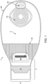
- the medical device or pouch 1 is formed from a front wall 2 and a rear wall 3.
- the front wall of the medical device generally faces away from the body, while the rear wall of the medical device or pouch generally faces towards the body.
- the front and rear wall may comprise at least two separate pieces of material joined together at the edges by adhesive or welding, or may be a single contiguous piece of material.
- the walls may be constructed of a suitable moisture impermeable material.
- the walls may be made of transparent or translucent material.
- the transparent or translucent walls may further comprise at least one flap that partially or fully covers the front wall.
- the flap can be manipulated to view the contents of the medical device or pouch and/or to assist a user or patient in attaching the device.
- the flap is opened or closed by a user or patient to view the contents of the medical device or pouch, or to assist in manipulation of the device or pouch onto, for example, the stoma of a patient.
- the flap material consists of the same water impermeable material as the front and rear walls.
- the flap material consists of a soft, breathable fabric that reduces irritation or chafing to the skin of a patient.
- the flap material may further be secured in a closed position to mask the contents within the pouch or medical device
- the front wall is made of transparent or translucent material and the rear wall is made of opaque material.
- the front and rear wall may be made of opaque material.
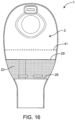
- the walls may be made of opaque material with a transparent window 24 for monitoring the contents of the medical device or pouch, or to assist in attaching the medical device or pouch directly or indirectly onto the patient.
- the transparent window may further comprise a flap that can be opened and closed to view the contents of the device and/or to assist the user or patient in attachment of the medical device or pouch.
- the material comprising the front and rear walls as well as the flap may be a plastic, thermoplastic, polymer or a natural substance.
- the material may be a laminate consisting of a plurality of layers or a single layer.
- Suitable materials include but are not limited to ethylene vinyl acetate (EVA), polyvinylidene chloride (PVDC), or ethylene vinyl alcohol (EVOH).
- the front and rear wall material further comprises an anti-microbial substance or coating, or the material itself has anti-microbial properties.
- Exemplary materials for a coating include, but are not limited to, metals or metal alloys of silver, gold, gallium , titanium, titanium dioxide or copper; organosilanes; and quaternary ammonium compounds such as 3-(Trimethoxysilyl) -propyldimethyloctadecyl ammonium chloride (Si-QAC).
- the front and rear wall material for the construction of the device walls provides controls for unpleasant odor.
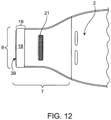
- the medical device or pouch further comprises a deodorizing filter and vent 22 for deodorizing and venting flatus.
- the filter is a strip filter or an axial filter.
- the strip filter or axial flow filter is wrapped with an odor barrier film around its perimeter.
- the filter has a low profile.
- an open cell foam is added as a pre-filter to prevent solid components from entering into and fouling the filter.
- the filter contains activated carbon.
- the medical device or pouch includes a first comfort layer covering at least part of the rear wall 3 and a second comfort layer covering at least part of the front wall 2.
- the front wall 2 is made of a transparent material
- a comfort layer does not cover the front wall 2.
- the rear wall 3 is made of an opaque material, it is covered, at least partially, by a comfort layer.
- the comfort layer is partially sealed to the front or rear wall that it covers so as to leave an access opening between the comfort layer(s) and the wall it is covering.
- the access opening is perpendicular to the longitudinal axis 27 of the medical device or pouch and proximate to where the walls taper to the outlet 7.
- Exemplary materials for the comfort layer include, but are not limited to, film, foam, woven or non-woven fabric.
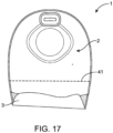
- the device contains a pocket 23 ( Fig. 16 ).
- the outlet 7, in the closed condition can be further folded and tucked into pocket 23 to allow for further security in the closure.
- the pocket 23 is attached to the front wall 2 of the device.
- the pocket 23 is attached to front wall 2 along the periphery of the pouch and has a top edge 25 and a bottom edge 26.
- the top edge 25 of pocket 23 is positioned below the horizontal centerline 41 of pouch 1.
- the top edge 25 of pocket 23 is positioned at the horizontal centerline 41 of pouch 1.
- the top edge 25 of pocket 23 is positioned above the horizontal centerline 41 of pouch 1.
- pocket 23 is made of the same material as that of at least one of the walls. In some embodiments, pocket 23 is made of a different material than that of the walls. Exemplary materials for the pocket include, but are not limited to, film, foam, woven or non-woven fabric.
- the rear wall 3 of the medical device or pouch ( Fig. 2 ) contains an opening comprising a stomal aperture 4 to allow connection to a stoma or peristomal area.
- the stomal aperture further connects to an adhesive wafer or gasket 5, which is attached to or around the stoma or peristomal area.
- the adhesive wafer contains a skin compatible adhesive or sealant for attaching the device to the peristomal skin.
- the adhesive or sealant is moldable.
- the adhesive wafer is removable from the device so that it might be positioned by the user around a stoma before the medical device or pouch is attached. In other embodiments, the adhesive wafer is attached to the medical device or pouch.
- the adhesive wafer 5 and/or stomal aperture 4 further comprise exemplary marks or indications 6 that allow the user to adjust the size of the aperture.
- the rear wall 3 may additionally comprise a coating or additional layer of material to enhance the comfort or breathability of the medical device or pouch when worn by a patient.
- the medical device or pouch further tapers to an outlet 7 ( Figs. 1 and 2 ) with an outlet opening 8.
- the outlet opening 8 is at the proximal end of the device.
- the outlet opening 8 may extend the entire width of the outlet.
- the opening may extend only partially the width of the outlet.
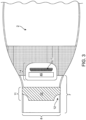
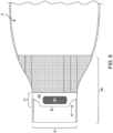
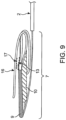
- the outlet is foldable from an open ( Figs. 3 and 4 ) to a closed condition ( Figs. 7 and 9 ).
- the outlet requires a single lateral fold.
- the outlet requires at least two lateral folds to be in a closed condition.
- the outlet requires two lateral folds to be in a closed condition.
- the outlet requires three lateral folds to be in a closed condition.
- the outlet requires four lateral folds to be in a closed condition. In certain embodiments, the outlet requires five lateral folds to be in a closed condition. In some embodiments, the lateral fold results in folding of the outlet in an upward direction away from the opening.
- the first reinforcing member is positioned above the second reinforcing member by a single lateral fold of the outlet. In some embodiments, the first reinforcing member is stacked on top of the second reinforcing member and the first fastener is stacked on top of the first reinforcing member by two lateral folds of the outlet. In some embodiments, the first fastener forms a linkage with the second fastener by three lateral folds of the outlet.
- the outlet has an opening system with at least a first reinforcing member 9 ( Fig. 4 ) and a second ( Fig. 3 ) reinforcing member 10, each of which is attached to an exterior surface of the device on the outlet 7.
- the first reinforcing member and the second reinforcing member are made of the same material. In some embodiments, the first reinforcing member and the second reinforcing member are made of different materials. In some embodiments, the first reinforcing member and the second reinforcing member are each independently made of a resiliently flexible, easily distensible plastic material. In some embodiments, the resiliently flexible easily distensible plastic material is not compressible. Non-limiting examples of resiliently flexible, easily distensible plastic material include polystyrene, polyethylene, polyurethane, polyester, polycarbonate. In preferred embodiments, the first and second reinforcing members are each made of polystyrene. In some embodiments, the first reinforcing member and the second reinforcing member are each independently made of a resiliently flexible metal sheet.
- the first and second reinforcing members are attached to opposing exterior surfaces on the walls.
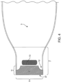
- the horizontal centerlines of the first and second reinforcing members may be offset with respect to each other as shown in Figs. 8 and 18 .
- the offset of the first and second reinforcing members may enable easy folding and handling of the medical device, for draining and closing. For example, users with poor dexterity may also benefit from the easy folding allowed by the offset of the first and second reinforcing members.
- the first and second reinforcing members may be vertically offset relative to each other, i.e., the vertical centerlines of the first and second reinforcing members may be offset relative to each other.
- the vertical centerline may be a line running along the axis 27 which extends from the proximal end to the distal end of the device.
- the horizontal centerline may be a line running along the axis 28 which runs perpendicular to the axis 27.
- the horizontal and vertical centerlines of the first and second reinforcing members may be offset relative to each other.
- the horizontal centerlines of the first and second reinforcing members may be offset relative to each other by about 0, 1, 2, 3, 4, 5, 6, 7, 8, 9, 10, 11, 12, 13, 14, 15, 16, 17, 18, 19, 20, 21, 22, 23, 24, 25, 26, 27, 28, 29, 30 mm or more.
- the vertical centerlines of the first and second reinforcing members may preferably be offset relative to each other by about 0, 1, 2, 3, 4, 5, 6, 7, 8, 9 or 10 mm or more. More preferably, the horizontal and/or vertical centerlines of the first and second reinforcing members may be offset relative to each other by about 0, 1, 2, 3, 4, 5, 6, 7, 8, 9, 10 mm or more. Most preferably, the horizontal and/or vertical centerlines of the first and second reinforcing members may be offset relative to each other by about 0, 1, 2, 3, 4, 5 mm or more. In some embodiments, the horizontal centerlines of the first and second reinforcing members are offset relative to each other by about 1-5 mm.
- the horizontal centerlines of the first and second reinforcing members are offset relative to each other by about 1-10 mm. In some embodiments, the horizontal centerlines of the first and second reinforcing members are offset relative to each other by about 1-20 mm. In some embodiments, the horizontal centerlines of the first and second reinforcing members are offset relative to each other by about 1-30 mm. In some embodiments, the horizontal centerlines of the first and second reinforcing members are offset relative to each other by about 5-10 mm. In some embodiments, the horizontal centerlines of the first and second reinforcing members are offset relative to each other by about 5-20 mm. In some embodiments, the horizontal centerlines of the first and second reinforcing members are offset relative to each other by about 5-30 mm.
- the horizontal centerlines of the first and second reinforcing members are offset relative to each other by about 10-20 mm. In some embodiments, the horizontal centerlines of the first and second reinforcing members are offset relative to each other by about 10-30 mm. In some embodiments, the horizontal centerlines of the first and second reinforcing members are offset relative to each other by about 20-30 mm. The horizontal centerlines of the first and second reinforcing members may not be offset with respect to each other, but positioned at equal distances from the edge of the outlet opening.
- the first and second reinforcing members may be offset relative to each other, along a longitudinal axis by about 0, 1, 2, 3, 4, 5, 6, 7, 8, 9, 10, 11, 12, 13, 14, 15, 16, 17, 18, 19, 20, 21, 22, 23, 24, 25, 26, 27, 28, 29, 30 mm or more. In some embodiments, the first and second reinforcing members may be offset relative to each other, along a longitudinal axis by about 1-5 mm. In some embodiments, the first and second reinforcing members may be offset relative to each other, along a longitudinal axis by about 1-10 mm. In some embodiments, the first and second reinforcing members may be offset relative to each other, along a longitudinal axis by about 1-20 mm.
- the first and second reinforcing members may be offset relative to each other, along a longitudinal axis by about 1-30 mm. In some embodiments, the first and second reinforcing members may be offset relative to each other, along a longitudinal axis by about 5-10 mm. In some embodiments, the first and second reinforcing members may be offset relative to each other, along a longitudinal axis by about 5-20 mm. In some embodiments, the first and second reinforcing members may be offset relative to each other, along a longitudinal axis by about 5-30 mm. In some embodiments, the first and second reinforcing members may be offset relative to each other, along a longitudinal axis by about 10-20 mm.
- first and second reinforcing members may be offset relative to each other, along a longitudinal axis by about 10-30 mm. In some embodiments, the first and second reinforcing members may be offset relative to each other, along a longitudinal axis by about 20-30 mm.
- the vertical centerlines of the first and second reinforcing members are offset relative to each other by about 1-5 mm. In some embodiments, the vertical centerlines of the first and second reinforcing members are offset relative to each other by about 1-10 mm. In some embodiments, the vertical centerlines of the first and second reinforcing members are offset relative to each other by about 1-20 mm. In some embodiments, the vertical centerlines of the first and second reinforcing members are offset relative to each other by about 1-30 mm. In some embodiments, the vertical centerlines of the first and second reinforcing members are offset relative to each other by about 5-10 mm. In some embodiments, the vertical centerlines of the first and second reinforcing members are offset relative to each other by about 5-20 mm.
- the vertical centerlines of the first and second reinforcing members are offset relative to each other by about 5-30 mm. In some embodiments, the vertical centerlines of the first and second reinforcing members are offset relative to each other by about 10-20 mm. In some embodiments, the vertical centerlines of the first and second reinforcing members are offset relative to each other by about 10-30 mm. In some embodiments, the vertical centerlines of the first and second reinforcing members are offset relative to each other by about 20-30 mm.
- a second reinforcing member 10 is distal to the opening 8 with respect to the first reinforcing member 9.
- the first reinforcing member 9 is immediately adjacent to the opening or its bottom edge 37 is offset from the opening by about 1, 2, 3, 4, 5, 6, 7, 8, 9, 10, 11, 12, 13, 14, 15, 16, 17, 18, 19, 20 mm or more.
- the bottom edge 37 of the first reinforcing member 9 is offset from the opening by about 1 mm. In some embodiments, the bottom edge 37 of the first reinforcing member 9 is offset from the opening by about 2 mm.
- the bottom edge 37 of the first reinforcing member 9 is offset from the opening by about 3 mm. In some embodiments, the bottom edge 37 of the first reinforcing member 9 is offset from the opening by about 4 mm. In some embodiments, the bottom edge 37 of the first reinforcing member 9 is offset from the opening by about 5 mm. In some embodiments, the bottom edge 37 of the first reinforcing member 9 is offset from the opening by about 6 mm. In some embodiments, the bottom edge 37 of the first reinforcing member 9 is offset from the opening by about 7 mm. In some embodiments, the bottom edge 37 of the first reinforcing member 9 is offset from the opening by about 8 mm.
- the bottom edge 37 of the first reinforcing member 9 is offset from the opening by about 9 mm. In some embodiments, the bottom edge 37 of the first reinforcing member 9 is offset from the opening by about 10 mm. In some embodiments, the bottom edge 37 of the first reinforcing member 9 is offset from the opening by more than about 10 mm. In some embodiments, the bottom edge 37 of the first reinforcing member 9 is offset from the opening by about 1-5 mm. In some embodiments, the bottom edge 37 of the first reinforcing member 9 is offset from the opening by about 1-10 mm. In some embodiments, the bottom edge 37 of the first reinforcing member 9 is offset from the opening by about 1-15 mm.
- the bottom edge 37 of the first reinforcing member 9 is offset from the opening by about 1-20 mm. In some embodiments, the bottom edge 37 of the first reinforcing member 9 is offset from the opening by about 3-10 mm. In some embodiments, the bottom edge 37 of the first reinforcing member 9 is offset from the opening by about 3-15 mm. In some embodiments, the bottom edge 37 of the first reinforcing member 9 is offset from the opening by about 3-20 mm. In some embodiments, the bottom edge 37 of the first reinforcing member 9 is offset from the opening by about 5-10 mm. In some embodiments, the bottom edge 37 of the first reinforcing member 9 is offset from the opening by about 5-15 mm.
- the bottom edge 37 of the first reinforcing member 9 is offset from the opening by about 5-20 mm. In some embodiments, the bottom edge 37 of the first reinforcing member 9 is offset from the opening by about 10-15 mm. In some embodiments, the bottom edge 37 of the first reinforcing member 9 is offset from the opening by about 10-20 mm.
- the length of the first reinforcing member 9 extends essentially the entire width of the opening 8. In some embodiments, the length of the second reinforcing member 10 extends essentially the entire width of the opening 8. In some embodiments, lengths of both the first reinforcing member 9 and the second reinforcing member 10 extend essentially the entire width of the opening 8. In some embodiments, the length of the first reinforcing member 9 extends essentially across the entire width of the opening 8 and the length of the second reinforcing member 10 extends essentially only partially across the width of the opening 8. In preferred embodiments, the length of the first reinforcing member 9 extends essentially the entire width of the opening 8. In preferred embodiments, the length of the second reinforcing member 10 extends essentially only partially across the width of the opening 8.
- both the first reinforcing member 9 and the second reinforcing member 10 are about of the same length.
- the first reinforcing member 9 is about 5, 10, 15, 20, 25, 30, 35, 40, 45, 50, 55 mm, 60 mm, 65 mm, 70 mm, 75 mm, 80 mm, 85 mm, or any increment thereof, long.
- the first reinforcing member 9 is about 5-85 mm long.
- the first reinforcing member 9 is about 5-80 mm long.
- the first reinforcing member 9 is about 5-40 mm long.
- the first reinforcing member 9 is about 5-70 mm long.
- the first reinforcing member 9 is about 5-60 mm long. In some embodiments, the first reinforcing member 9 is about 5-55 mm long. In some embodiments, the first reinforcing member 9 is about 5-50 mm long. In some embodiments, the first reinforcing member 9 is about 5-40 mm long. In some embodiments, the first reinforcing member 9 is about 5-30 mm long. In some embodiments, the first reinforcing member 9 is about 5-20 mm long. In some embodiments, the first reinforcing member 9 is about 5-10 mm long. In some embodiments, the first reinforcing member 9 is about 75-80 mm long.
- the second reinforcing member 10 is about 5, 10, 15, 20, 25, 30, 35, 40, 45, 50, 55 mm, 60 mm, 65 mm, 70 mm, 75 mm, 80 mm, 85 mm, or any increment thereof, long. In some embodiments, the second reinforcing member 10 is about 5-85 mm long. In some embodiments, the second reinforcing member 10 is about 5-80 mm long. In some embodiments, the second reinforcing member 10 is about 5-40 mm long. In some embodiments, the second reinforcing member 10 is about 5-70 mm long. In some embodiments, the second reinforcing member 10 is about 5-60 mm long. In some embodiments, the second reinforcing member 10 is about 5-50 mm long.
- the second reinforcing member 10 is about 5-40 mm long. In some embodiments, the second reinforcing member 10 is about 5-40 mm long. In some embodiments, the second reinforcing member 10 is about 5-30 mm long. In some embodiments, the second reinforcing member 9 is about 5-20 mm long. In some embodiments, the second reinforcing member 10 is about 5-10 mm long. In some embodiments, the second reinforcing member 10 is about 75-80 mm long.
- the lengths of the first (9) and second (10) reinforcing members are correlated with preventing incidences of leak from the medical device disclosed herein when it is in a closed condition.
- the probability of an incidence of leak is about 10% to about 25% less in a medical device where first (9) and second (10) reinforcing members are 80 mm long than in a medical device where the first (9) and second (10) reinforcing members are 50 mm long.
- the first reinforcing member 9 is about 2, 3, 4, 5, 6, 7, 8, 9, 10, 11, 12, 13, 14, 15, 16, 17, 18, 19, or 20 mm wide. In some embodiments, the first reinforcing member 9 is about 2-20 mm wide. In some embodiments, the first reinforcing member 9 is about 5-20 mm wide. In some embodiments, the first reinforcing member 9 is about 10-20 mm wide. In some embodiments, the second reinforcing member 10 is about 2, 3, 4, 5, 6, 7, 8, 9, 10, 11, 12, 13, 14, 15, 16, 17, 18, 19, or 20 mm wide. In some embodiments, the second reinforcing member 10 is about 2-20 mm wide. In some embodiments, the second reinforcing member 10 is about 5-20 mm wide.
- the second reinforcing member 10 is about 10-20 mm wide. In some embodiments, the first reinforcing member 9 and the second reinforcing member 10 are offset from each other, along the vertical axis 28, by about 1 mm to about 5 mm. In some embodiments, the widths of the first 9 and second 10 reinforcing members are dependent on the type of material used for the reinforcing members. In some embodiments, the widths of the first 9 and second 10 reinforcing members are proportional to their flexibility. In some embodiments, the first reinforcing member 9 and the second reinforcing member 10 are made of polystyrene and are about 20 mm wide.
- first reinforcing member 9 and the second reinforcing member 10 are made of polyethylene and are about 15 mm wide. In preferred embodiments, the first reinforcing member 9 and the second reinforcing member 10 are made of polystyrene.
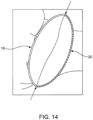
- the first reinforcing member 9 and the second reinforcing member 10 have lateral edges 11 .
- the lateral edges are deformable by application of pressure.
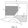
- Fig. 11 is a sideview of the outlet in use illustrating the application of pressure to the first reinforcing member 9 and the second reinforcing member 10, of the first embodiment, as the opening 8 is radially distended and opened for drainage. A user squeezes together the lateral edges of reinforcing member 9 and reinforcing 10 at the peripheral edge of the outlet 33.
- the reinforcing member While reinforcing member 9 is placed away from edge of the opening 8 in this view, the reinforcing member may be at or near the opening edge 8, for example, at a distance of about 0, 1, 2, 3, 4, 5, 6, 7, 8, 9, 10, 11, 12, 13, 14, 15, 16, 17, 18, 19, 20 mm or more from the opening edge 8.
- pressure may be applied to the lateral edges of the first reinforcing member 9 and the second reinforcing member 10 to push the edges from its flat un-deformed state to a curved deformed state inward towards the midline of the opening 8, thereby radially distending the opening 8. Such deformation is reversible when the pressure is removed.
- the first reinforcing member 9 and the second reinforcing member 10 have corners that are notched, grooved, cut-to-shape or the like.
- the first reinforcing member 9 and the second reinforcing member 10 may have corners that are square, rounded, flared, or have material removed, creating a void 12 ( Figs. 3 and 4 ) to facilitate finger positioning by a user.
- the material can be removed from either a single lateral edge or from both lateral edges.
- the shape of the first and second reinforcing members may enable easy handling of the medical device, for draining and closing.
- a user may have his/her fingers fit the notched or voided region of the first and second reinforcing member, to open or close the outlet with ease. Further, users with poor dexterity may also benefit from the notched or voided design of the first and second reinforcing members.
- the reinforcing member may have corners that are grooved, cut-to-shape or the like to allow finger positioning by a user.
- the first reinforcing member 9 may be positioned above to the second reinforcing member 10 by a single lateral fold of the outlet. In some embodiments, the first reinforcing member 9 may be stacked on top of the second reinforcing member 10 and the first fastener 13 may be stacked on top of the first reinforcing member by two lateral folds of the outlet. In some embodiments, the first fastener 13 may form a linkage with the second fastener 17 by three lateral folds of the outlet, as seen in Fig. 9 .
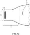
- the bottom edge 38 of the first reinforcing member 29 is distal to the opening 8, with respect to the second reinforcing member 30.
- the bottom edge 38 of the second reinforcing member 30 is immediately adjacent to the opening or its bottom edge 38 is offset from the opening by about 1, 2, 3, 4, 5, 6, 7, 8, 9, 10 mm or more.
- the bottom edge 38 of the second reinforcing member 30 is offset from the opening by about 1, 2, 3, 4, 5, 6, 7, 8, 9, 10, 11, 12, 13, 14, 15, 16, 17, 18, 19, 20 mm or more.
- the bottom edge 38 of the second reinforcing member 30 is offset from the opening by about 1 mm. In some embodiments, the bottom edge 38 of the second reinforcing member 30 is offset from the opening by about 2 mm. In some embodiments, the bottom edge 38 of the second reinforcing member 30 is offset from the opening by about 3 mm. In some embodiments, the bottom edge 38 of the second reinforcing member 30 is offset from the opening by about 4 mm. In some embodiments, the bottom edge 38 of the second reinforcing member 30 is offset from the opening by about 5 mm. In some embodiments, the bottom edge 38 of the second reinforcing member 30 is offset from the opening by about 6 mm.
- the bottom edge 38 of the second reinforcing member 30 is offset from the opening by about 7 mm. In some embodiments, the bottom edge 38 of the second reinforcing member 30 is offset from the opening by about 8 mm. In some embodiments, the bottom edge 38 of the second reinforcing member 30 is offset from the opening by about 9 mm. In some embodiments, the bottom edge 38 of the second reinforcing member 30 is offset from the opening by about 10 mm. In some embodiments, the bottom edge 38 of the second reinforcing member 30 is offset from the opening by more than about 10 mm. In some embodiments, the bottom edge 38 of the second reinforcing member 30 is offset from the opening by about 1-5 mm.
- the bottom edge 38 of the second reinforcing member 30 is offset from the opening by about 1-10 mm. In some embodiments, the bottom edge 38 of the second reinforcing member 30 is offset from the opening by about 1-15 mm. In some embodiments, the bottom edge 38 of the second reinforcing member 30 is offset from the opening by about 1-20 mm. In some embodiments, the bottom edge 38 of the second reinforcing member 30 is offset from the opening by about 3-10 mm. In some embodiments, the bottom edge 38 of the second reinforcing member 30 is offset from the opening by about 3-15 mm. In some embodiments, the bottom edge 38 of the second reinforcing member 30 is offset from the opening by about 3-20 mm.
- the bottom edge 38 of the second reinforcing member 30 is offset from the opening by about 5-10 mm. In some embodiments, the bottom edge 38 of the second reinforcing member 30 is offset from the opening by about 5-15 mm. In some embodiments, the bottom edge 38 of the second reinforcing member 30 is offset from the opening by about 5-20 mm. In some embodiments, the bottom edge 38 of the second reinforcing member 30 is offset from the opening by about 10-15 mm. In some embodiments, the bottom edge 38 of the second reinforcing member 30 is offset from the opening by about 10-20 mm.
- the length of the first reinforcing member 29 essentially extends the entire width of the opening 8. In some embodiments, the length of the second reinforcing member 30 essentially extends the entire width of the opening 8. In some embodiments, lengths of both the first reinforcing member 29 and the second reinforcing member 30 essentially extend the entire width of the opening 8. In some embodiments, the length of the first reinforcing member 29 essentially extends across the entire width of the opening 8 and the length of the second reinforcing member 30 essentially extends only partially across the width of the opening 8. In preferred embodiments, the length of the first reinforcing member 29 essentially extends the entire width of the opening 8. In preferred embodiments, the length of the second reinforcing member 30 essentially extends only partially across the width of the opening 8.
- both the first reinforcing member 29 and the second reinforcing member 30 are the same length.
- the first reinforcing member 29 is about 5, 10, 15, 20, 25, 30, 35, 40, 45, 50, 55 mm, 60 mm, 65 mm, 70 mm, 75 mm, 80 mm, 85 mm, or any increment thereof, long.
- the first reinforcing member 29 is about 5-55 mm long.
- the first reinforcing member 29 is about 5-85 mm long.
- the first reinforcing member 29 is about 5-80mm long.
- the first reinforcing member 29 is about 5-70 mm long.
- the first reinforcing member 29 is about 5-60 mm long. In some embodiments, the first reinforcing member 29 is about 5-50 mm long. In some embodiments, the first reinforcing member 29 is about 5-40 mm long. In some embodiments, the first reinforcing member 29 is about 5-40 mm long. In some embodiments, the first reinforcing member 29 is about 5-30 mm long. In some embodiments, the first reinforcing member 29 is about 5-20 mm long. In some embodiments, the first reinforcing member 29 is about 5-10 mm long. In some embodiments, the first reinforcing member 29 is about 75-80 mm long.
- the second reinforcing member 30 is about 5, 10, 15, 20, 25, 30, 35, 40, 45, 50, 55 mm, 60 mm, 65 mm, 70 mm, 75 mm, 80 mm, 85 mm, or any increment thereof, long. In some embodiments, the second reinforcing member 30 is about 5-85 mm long. In some embodiments, the second reinforcing member 30 is about 5-80 mm long. In some embodiments, the second reinforcing member 30 is about 5-70 mm long. In some embodiments, the second reinforcing member 30 is about 5-60 mm long. In some embodiments, the second reinforcing member 30 is about 5-50 mm long. In some embodiments, the second reinforcing member 30 is about 5-40 mm long.
- the second reinforcing member 30 is about 5-40 mm long. In some embodiments, the second reinforcing member 30 is about 5-30 mm long. In some embodiments, the second reinforcing member 30 is about 5-20 mm long. In some embodiments, the second reinforcing member 30 is about 5-10 mm long. In some embodiments, the second reinforcing member 30 is about 75-80 mm long.
- the lengths of the first (29) and second (30) reinforcing members are correlated with preventing incidences of leak from the medical device disclosed herein when it is in a closed condition.
- the probability of an incidence of leak is about 10% to about 25% less in a medical device where first (29) and second (30) reinforcing members are 80 mm long than in a medical device where the first (29) and second (30) reinforcing members are 50 mm long.
- the first reinforcing member 29 is about 2, 3, 4, 5, 6, 7, 8, 9, 10, 11, 12, 13, 14, 15, 16, 17, 18, 19, or 20 mm wide. In some embodiments, the first reinforcing member 29 is about 2-20 mm wide. In some embodiments, the first reinforcing member 29 is about 5-20 mm wide. In some embodiments, the first reinforcing member 29 is about 10-20 mm wide. In some embodiments, the second reinforcing member 30 is about 2, 3, 4, 5, 6, 7, 8, 9, 10, 11, 12, 13, 14, 15, 16, 17, 18, 19, or 20 mm wide. In some embodiments, the second reinforcing member 30 is about 2-20 mm wide. In some embodiments, the second reinforcing member 30 is about 5-20 mm wide. In some embodiments, the second reinforcing member 10 is about 10-20 mm wide.
- the widths of the first 29 and second 30 reinforcing members are dependent on the type of material used for the reinforcing members. In some embodiments, the widths of the first 29 and second 30 reinforcing members are proportional to their flexibility. In some embodiments, the first reinforcing member 29 and the second reinforcing member 30 are made of polystyrene and are about 20 mm wide. In some embodiments, the first reinforcing member 29 and the second reinforcing member 30 are made of polyethylene and are about 15 mm wide. In preferred embodiments, the first reinforcing member 29 and the second reinforcing member 30 are made of polystyrene.
- the first reinforcing member 29 and the second reinforcing member 30 have lateral edges 11.
- the lateral edges are deformable by application of pressure.
- the first reinforcing member 29 and the second reinforcing member 30 have corners that are notched, square, rounded, flared, or have material removed, creating a void 12 ( Figs. 5 and 6 ), to facilitate finger positioning by a user.
- the material removed can be wedge shaped 12 ( Figs. 5 and 6 ) or triangular 32 ( Fig. 10 ).
- the material can be removed from either a single lateral edge or from both lateral edges.
- the reinforcing member may have corners that are grooved, cut-to-shape or the like to allow finger positioning by a user.
- the first or second embodiment of the medical device with an opening system may further comprise a securing system for securing the opening in the closed condition.
- the securing system has a first fastener 13, attached to an exterior wall of the medical device or pouch; and a security flap 14.
- the first fastener 13 and the security flap 14 may be attached to opposing walls of the medical device or pouch 1.
- the security flap 14 is attached to the front wall 2 and the first fastener 13 is directly attached to the rear wall 3, as shown in Figs. 3 and 4 , respectively.
- the bottom edge of the first fastener 13 is immediately adjacent to or offset relative to the top edge of the first reinforcing member 9.
- the bottom edge of the first fastener 13 is immediately adjacent to the top edge of the first reinforcing member 9. In these embodiments, the bottom edge of the first fastener 13 is offset relative to the top edge of the first reinforcing member 9 by about 1, 2, 3, 4, 5, 6, 7, 8, 9, 10, 11, 12, 13, 14, 15, 16, 17, 18, 19, 20, 25, 30, 35, 40, 45, 50 mm or more, or any increment thereof. In these embodiments, the bottom edge of the first fastener 13 is offset relative to the top edge of the first reinforcing member 9 by about 1-100 mm. In these embodiments, the bottom edge of the first fastener 13 is offset relative to the top edge of the first reinforcing member 9 by about 1-50 mm.
- the bottom edge of the first fastener 13 is offset relative to the top edge of the first reinforcing member 9 by about 1-20 mm. In these embodiments, the bottom edge of the first fastener 13 is offset relative to the top edge of the first reinforcing member 9 by about 1-10 mm.
- the security flap 14 is attached to the front wall 2 and the first fastener 13 is attached to the first reinforcing member 29 located on the rear wall 3, as shown in Figs. 5 and 6 , respectively. As illustrated in the first embodiment shown in Fig.
- the security flap 14 comprises a first portion 15 attached to one of the opposing walls of the medical device or pouch, on the outlet 7, and a second portion 16 freely extended outward from the same opposing wall of the medical device or pouch 1, on the outlet 7.
- the security flap 14 may be provided on the front wall 2 of the medical device or pouch 1, as shown in Figs. 3 , 5 and 8 .
- the security flap 14 may be fastened to the front wall 2, for example by welding or by adhesive, or it may be an extension of a layer or portion forming the front wall 2.
- the freely extended portion 16 of security flap 14 is configured to be folded over the outlet 7 when the outlet is in the closed condition.
- the securing system may further comprise a second fastener 17, wherein the second fastener is attached to the freely extended portion 16 of the security flap, as shown in Fig. 8 .
- the freely extended portion 16 of the security flap 14 is folded over the outlet 7 when the outlet is in the closed condition, and secured by the formation of a linkage between the first fastener 13 and second fastener 17.
- the first fastener 13 and the second fastener 17 are able to form a linkage after at least two lateral folds as shown in Figs. 7 and 9 .
- the freely extended portion 16 of the security flap 14 is folded over the outlet 7 when the outlet is in the closed condition, by forming a linkage between the first fastener 13 and second fastener 17 (not shown).
- the first fastener 13 on the rear wall 3 may be approximately in register with the second reinforcing member 10 on the front wall 2.
- the security flap 14 prevents the outlet 7 from dropping down to its draining position (i.e ., opened condition) while the security flap 14 is in its fastened condition.
- the security flap comprises a semi-rigid or elasticized material capable of maintaining its shape after repeated closure.
- the security flap comprises a memory foam-like material.
- the security flap comprises film.
- the security flap comprises a fabric.
- the fabric is a woven fabric or a non-woven fabric.
- the first and second fasteners may be hook-and-loop fasteners, hook-and-pile fasteners, touch fasteners, adhesive couplings, molded couplings, formed couplings, snap closures, or hook and hook fasteners.
- Velcro TM is an exemplary hook and loop fastener.
- the first and second fasteners are hook-and-loop fasteners.
- the first and second fasteners are hook-and-pile fasteners.
- the first and second fasteners are touch fasteners.
- the first and second fasteners are adhesive couplings.
- the first and second fasteners are molded couplings.
- the first and second fasteners are formed couplings. In some embodiments, the first and second fasteners are snap closures. In some embodiments, the first and second fasteners are hook and hook fasteners. In certain embodiments, any of the fasteners re fixed directly to the pouch. In certain embodiments, any of the fasteners are fixed to one of the reinforcing members. In certain embodiments, the any of the fasteners itself serves as a reinforcing member.
- Figs. 12 , 13 and 14 are exemplary of a third embodiment of a medical device with an opening system not in accordance with the present invention.
- This embodiment has a single reinforcing member 18 attached to an exterior surface of the device near the opening 8.
- the single reinforcing member 18 may be immediately adjacent to the opening, as shown in Fig. 12 .
- the bottom edge 39 of the single reinforcing member 18 may be offset from the opening by about 1, 2, 3, 4, 5, 6, 7, 8, 9, 10, 11, 12, 13, 14, 15, 16, 17, 18, 19, 20 mm or more.
- the bottom edge 39 of the single reinforcing member 18 is offset from the opening by about 1 mm.
- the bottom edge 39 of the single reinforcing member 18 is offset from the opening by about 2 mm. In some embodiments, the bottom edge 39 of the single reinforcing member 18 is offset from the opening by about 3 mm. In some embodiments, the bottom edge 39 of the single reinforcing member 18 is offset from the opening by about 4 mm. In some embodiments, the bottom edge 39 of the single reinforcing member 18 is offset from the opening by about 5 mm. In some embodiments, the bottom edge 39 of the single reinforcing member 18 is offset from the opening by about 6 mm. In some embodiments, the bottom edge 39 of the single reinforcing member 18 is offset from the opening by about 7 mm.
- the bottom edge 39 of the single reinforcing member 18 is offset from the opening by about 8 mm. In some embodiments, the bottom edge 39 of the single reinforcing member 18 is offset from the opening by about 9 mm. In some embodiments, the bottom edge 39 of the single reinforcing member 18 is offset from the opening by about 10 mm. In some embodiments, the bottom edge 39 of the single reinforcing member 18 is offset from the opening by more than about 10 mm. In some embodiments, the bottom edge 39 of the single reinforcing member 18 is offset from the opening by about 1-5 mm. In some embodiments, the bottom edge 39 of the single reinforcing member 18 is offset from the opening by about 1-10 mm.
- the bottom edge 39 of the single reinforcing member 18 is offset from the opening by about 1-15 mm. In some embodiments, the bottom edge 39 of the single reinforcing member 18 is offset from the opening by about 1-20 mm. In some embodiments, the bottom edge 39 of the single reinforcing member 18 is offset from the opening by about 3-10 mm. In some embodiments, the bottom edge 39 of the single reinforcing member 18 is offset from the opening by about 3-15 mm. In some embodiments, the bottom edge 39 of the single reinforcing member 18 is offset from the opening by about 3-20 mm. In some embodiments, the bottom edge 39 of the single reinforcing member 18 is offset from the opening by about 5-10 mm.
- the bottom edge 39 of the single reinforcing member 18 is offset from the opening by about 5-15 mm. In some embodiments, the bottom edge 39 of the single reinforcing member 18 is offset from the opening by about 5-20 mm. In some embodiments, the bottom edge 39 of the single reinforcing member 18 is offset from the opening by about 10-15 mm. In some embodiments, the bottom edge 39 of the single reinforcing member 18 is offset from the opening by about 10-20 mm.
- the single reinforcing member 18 essentially extends the entire width of the opening 8. In other embodiments, the single reinforcing member 18 essentially extends only partially across the width of the opening 8. In some embodiments, the single reinforcing member 18 is about 5, 10, 15, 20, 25, 30, 35, 40, 45, 50, 55 mm, 60 mm, 65 mm, 70 mm, 75 mm, 80 mm, or 85 mm, or any increment thereof, long. In some embodiments, the single reinforcing member 18 is about 5-85 mm long. In some embodiments, the single reinforcing member 18 is about 5-80 mm long. In some embodiments, the single reinforcing member 18 is about 5-60 mm long.
- the single reinforcing member 18 is about 5-70 mm long. In some embodiments, the single reinforcing member 18 is about 5-50 mm long. In some embodiments, the single reinforcing member 18 is about 5-40 mm long. In some embodiments, the single reinforcing member 18 is about 5-25 mm long. In some embodiments, the single reinforcing member 18 is about 5-30 mm long. In some embodiments, the single reinforcing member 18 is about 5-20 mm long. In some embodiments, the single reinforcing member 18 is about 5-10 mm long. In some embodiments, the single reinforcing member 18 is about 75-80 mm long.
- the single reinforcing member 18 has lateral edges 19.
- the reinforcing member 18 is deformable by the application of manual pressure to its lateral edges, optionally in the direction of the arrows from its flat un-deformed state to a curved deformed state as shown in Fig. 14 .
- the outlet opening distends radially under the pressure. Such deformation is reversible when the pressure is removed.
- the reinforcing member has corners that are notched, square, rounded, flared or have material removed, creating a void, to facilitate finger positioning by a user.
- the material removed can be wedge shaped or triangular.
- the reinforcing member may have corners that are grooved, cut-to-shape or the like to allow finger positioning by a user.
- the third embodiment of the medical device with an opening system may further comprise a first fastener 20 and a second fastener 21, attached to opposing exterior surfaces on the walls, as shown in Figs. 12 and 13 .
- the first fastener 20 may be opposite the single reinforcing member 18.
- the horizontal and/or vertical centerlines of both the single reinforcing member 18 and the first fastener 20 are aligned with one another.
- the horizontal and/or vertical centerlines of the single reinforcing member 18 and the first fastener 20 are offset relative to one another by about 0, 1, 2, 3, 4, 5, 6, 7, 8, 9, 10, 11, 12, 13, 14, 15, 16, 17, 18, 19, 20, 21, 22, 23, 24, 25, 26, 27, 28, 29, 30 mm or more.
- the horizontal and/or vertical centerlines of the single reinforcing member 18 and the first fastener 20 may be offset relative to each other by about 0, 1, 2, 3, 4, 5, 6, 7, 8, 9, 10 mm or more.
- the single reinforcing member 18 and the first fastener 20 may be vertically and/or horizontally offset relative to each other by about 0, 1, 2, 3, 4, 5 mm or more.
- the second fastener 21 is opposite the first fastener 20 and distal to the opening 8 with respect to the single reinforcing member 18.
- the horizontal centerline of second fastener 21 is offset relative to the horizontal centerline of the single reinforcing member 18 by about 20, 25, 30, 35, 40, 45, 50, 55, 60, 65, 70, 75, 80, 85, 90, 95, or 100 mm, or increments thereof.
- the horizontal centerline of second fastener 21 is offset relative to the horizontal centerline of the single reinforcing member 18 by about 20-100 mm.
- the horizontal centerline of second fastener 21 is offset relative to the horizontal centerline of the single reinforcing member 18 by about 20-90 mm. In some embodiments, the horizontal centerline of second fastener 21 is offset relative to the horizontal centerline of the single reinforcing member 18 by about 20-80 mm. In some embodiments, the horizontal centerline of second fastener 21 is offset relative to the horizontal centerline of the single reinforcing member 18 by about 20-70 mm. In some embodiments, the horizontal centerline of second fastener 21 is offset relative to the horizontal centerline of the single reinforcing member 18 by about 20-60 mm. In some embodiments, the horizontal centerline of second fastener 21 is offset relative to the horizontal centerline of the single reinforcing member 18 by about 20-50 mm.
- first fastener 20 and the second fastener 21 are hook-and-loop fasteners, hook-and-pile fasteners, or touch fasteners, adhesive coupling, molded couplings, formed couplings, snap closures, or hook and hook fasteners.
- Velcro TM is an exemplary hook and loop fastener.
- the first fastener 20 and the second fastener 21 are hook-and-loop fasteners.
- the first fastener 20 and the second fastener 21 are hook-and-pile fasteners.
- the first fastener 20 and the second fastener 21 are touch fasteners.
- first fastener 20 and the second fastener 21 are adhesive couplings. In some embodiments, the first fastener 20 and the second fastener 21 are molded couplings. In some embodiments, the first fastener 20 and the second fastener 21 are formed couplings. In some embodiments, the first fastener 20 and the second fastener 21 are snap closures. In some embodiments, the first fastener 20 and the second fastener 21 are hook and hook fasteners.
- the first fastener 20 may lie directly on top of, and be attached to, a second reinforcing member (not shown). In this third embodiment, the first fastener 20 and second fastener 21 can form a linkage after at least two lateral folds of the outlet 7.
- the aforementioned third embodiment may also have a securing system
- the securing system consists of a third fastener (not shown) attached to one exterior wall, and a security flap (not shown) attached to an exterior surface of the outlet with one end extending freely, having a fourth fastener.
- the fourth fastener may be able to form a linkage with the third fastener after at least two lateral folds of the outlet.
- the outlet requires a single lateral fold.
- the outlet requires two lateral folds to be in a closed condition.
- the outlet requires three lateral folds to be in a closed condition.
- the outlet requires four lateral folds to be in a closed condition.
- the outlet requires five lateral folds to be in a closed condition.
- the lateral folds are carried out in an upward direction with respect to the opening 8 such that the outlet 7 is folded from an open to a closed condition.
- the third and the fourth fastener form a linkage after three lateral folds of the outlet.
- the third and the fourth fastener form a linkage after four lateral folds of the outlet.
- the third and the fourth fastener form a linkage after five lateral folds of the outlet.
- the medical device with an opening system further comprises one or more support members (not shown), distinct from the reinforcing members in that they do not essentially extend for the entire width of the opening. These supports can aid in the radial distension of the opening (not shown).
- the support members are made of the same material as the reinforcing member.
- the support members are made of a different material than the reinforcing member.
- the support members are about 5, 10, 15, 20, 25, 30, 35, 40, 45, 50, 55 mm, 60 mm, 65 mm, or 70 mm, or any increment thereof, long. In some embodiments, the support members are about 5-70 mm long.
- the support members are about 5-65 mm long. In some embodiments, the support members are about 5-60 mm long. In some embodiments, the support members are about 5-55 mm long. In some embodiments, the support members are about 5-50 mm long. In some embodiments, the support members are about 5-50 mm long. In some embodiments, the support members are about 5-40 mm long. In some embodiments, the support members are about 5-30 mm long. In some embodiments, the support members are about 5-20 mm long. In some embodiments, the support members are about 5-10 mm long.
- the length of the support members is 5-20% less than the length of the reinforcing members. In some embodiments, the length of the support members is about 5% less than the length of the reinforcing members. In some embodiments, the length of the support members is about 10% less than the length of the reinforcing members. In some embodiments, the length of the support members is about 15% less than the length of the reinforcing members. In some embodiments, the length of the support members is about 20% less than the length of the reinforcing members.
- the one or more support members are attached to the front wall 2. In some embodiments, the one or more support members, are positioned between the second reinforcing member 10 and the security flap 14. In some embodiments, the one or more support members are attached to the front wall 2. In some embodiments, the one or more support members, are positioned within the outlet, above the first reinforcing member 9.
- the medical device with an opening system further includes a flap 31 present between the front wall 2 and the rear wall 3, as illustrated in Fig. 15 .
- the flap 31 is welded to the front wall 2.
- the flap 31 has a partially free edge portion that is attached intermittently 34 to the inner surface of the front wall 2 and has openings 35 that permit odorous gas to reach the filter assembly 22 for deodorization while deterring a ballooning of the pouch 1 due to captured gas within the pouch.
- the flap 31 essentially extends partially down from the top edge 36 of the medical device or pouch 1 so as to at least partially and preferably totally cover and protect the filter assembly 22 from any body waste material entering the medical device or pouch 1 through the stomal aperture 4.
- the top edge of the flap 31 is about 5 mm, about 10 mm, about 15 mm, about 20 mm, or about 25 mm, or any increments thereof, below the top edge 36 of the medical device or pouch 1.
- the top edge of the flap 31 is about 5- 25 mm below the top edge 36 of the medical device or pouch 1.
- the top edge of the flap 31 is about 5- 20 mm below the top edge 36 of the medical device or pouch 1.
- the top edge of the flap 31 is about 5-15 mm below the top edge 36 of the medical device or pouch 1. In some embodiments, the top edge of the flap 31 is about 5-10 mm below the top edge 36 of the medical device or pouch 1. In some embodiments, the top edge of the flap 31 is about 15- 20 mm below the top edge 36 of the medical device or pouch 1.
- the partially free edge portion 32 of the flap is welded to the inner wall of the front wall 2 by one or more spot welds. In some embodiments, the partially free edge portion of the flap is welded to the inner wall of the front wall 2 by four spot welds.
- This disclosure also provides for methods of manufacture of the medical device or pouch with an opening system.
- Components can be positioned onto a substrate by hand in a sequential process using fixtures.
- a manual or automated web process can be used in conjunction with automatic dispensing, pick and place or other automatic transport to position the components onto a substrate.
- the components can be attached to the substrate by bonding, sealing or adhesive attachment.
Description
- This application claims priority from
U.S. Provisional Application No. 62/241,716 filed October 14, 2015 - Disclosed within are opening systems for medical devices. The medical device is for collecting, storing and/or disposing of bodily fluids or waste. The medical device is an ostomy bag or pouch.
- Medical devices and ostomy pouches for the removal and storage of bodily fluids are used by many patients every day. Various drainable ostomy pouches having a range of closure mechanisms are disclosed for example in
US 2004/0068243 A1 ,US 2012/0022478 A1 ,WO 2007/115575 A1 ,WO 2006/031275 A2 andUS 2007/0265588 A1 . Conditions that affect the bladder and digestive system can lead to the necessity of an ostomy, which is a temporary, or permanent, surgical creation of an opening, or stoma, from a part of the body such as the bladder or intestines to the outside of the body. There are many different types of ostomy such as colostomy, ileostomy or urostomy. - The present invention provides an ostomy pouch comprising (a) opposing walls having a cavity therebetween, the walls joined along their peripheries, and tapering to an outlet opening at the proximal end of the device; (b) first and second deformable reinforcing members attached to opposing exterior surfaces of said opposing walls, wherein each reinforcing member has two lateral edges deformable by manual application of pressure to said lateral edges, so as to radially distend the outlet opening, wherein the first and second deformable reinforcing members are offset from each other along a longitudinal axis, and wherein the lateral edges of the first and second reinforcing members have material removed to create corners with void space; and (c) first and second fasteners; wherein the outlet is flexible and foldable from an open condition to a closed condition by one or more folds. Also disclosed are improved methods to easily and reliably drain bodily waste from a reusable and drainable medical device such as an ostomy pouch. The features disclosed herein may permit users with limited dexterity and strength to manipulate, open and seal the drainable pouch.
- Disclosed herein are medical devices comprising a closable opening for the storage, removal and sanitary disposal of waste and bodily fluids. The medical device is an ostomy pouch. In one embodiment is described a medical device with an opening system comprising (a) opposing walls having a cavity therebetween, the walls joined along their peripheries, and tapering to an outlet opening; (b) first and second deformable reinforcing members attached to opposing exterior surfaces of said opposing walls, wherein each reinforcing member has two lateral edges deformable by manual application of pressure to said lateral edges, so as to radially distend the outlet opening, wherein the first and second deformable reinforcing members are offset from each other along a longitudinal axis; and (c) first and second fasteners; wherein the outlet is flexible and foldable from an open condition to a closed condition by one or more folds. In some embodiments, the medical device with an opening system further comprises (d) a system for securing the device in the closed condition, the system comprising: a security flap, wherein said flap is attached to the same exterior surface of one of said opposing walls as the second reinforcing member, distal to the opening of the outlet with respect to the second reinforcing member, wherein a portion of the flap extends freely from the exterior surface of the opposing wall on which the flap is attached; and wherein the first fastener is attached to the same exterior surface of one of said opposing walls as said first reinforcing member, distal to the opening with respect to said first reinforcing member, the second fastener is attached to the freely opened portion of said security flap, and wherein the first fastener and the second fastener are capable of forming a linkage when the outlet is in the closed condition. In some embodiments, at least one of the first and second fasteners is a hook and loop fastener. In some embodiments, the first deformable reinforcing member is near the outlet opening, and the second deformable reinforcing member is distal to the outlet opening with respect to the first deformable reinforcing member. In some embodiments, the second deformable reinforcing member is near the outlet opening, and the first deformable reinforcing member is distal to the outlet opening with respect to the second deformable reinforcing member. In some embodiments, the first and second deformable reinforcing members differ in size. In some embodiments, the first and second deformable reinforcing members differ in shape. In some embodiments, the lateral edges of the first and second reinforcing members are notched. In some embodiments, the lateral edges of the first and second reinforcing members are grooved, cut-to-shape or the like. In some embodiments, at least one of the first and second deformable reinforcing members extend the entire width of the outlet opening. In some embodiments, at least one of the first and second fasteners extends the entire width of the outlet opening. In some embodiments, the first and second fasteners differ in size and shape. In some embodiments, the first and second fastener form a linkage after at least two folds of the outlet from the open towards the closed position. In some embodiments, the first and second fastener form a linkage after two lateral folds of the outlet.
- Another embodiment provides a medical device with an opening system comprising: (a) opposing walls having a cavity therebetween, the walls joined along their peripheries, and tapering to an outlet opening at the proximal end of the device; (b) a deformable reinforcing member on one exterior surface of said opposing walls, near the outlet opening, said reinforcing member having two lateral edges deformable by manual application of pressure to said lateral edges, so as to radially distend the outlet opening, wherein the lateral edge of the reinforcing member is notched, grooved, cut-to-shape or the like; and (c) a first fastener and a second fastener attached to opposing exterior surfaces of said opposing walls, wherein one of said first and second fastener is near the outlet opening; wherein the outlet is flexible and foldable from an opened condition to a closed condition by one or more folds, and wherein the first and second fastener are capable of forming a linkage when said outlet is in the closed condition. In some embodiments, the medical device further comprises a system for securing the device in the closed condition, the system comprising (d) a security flap, wherein said flap is attached to one exterior surface of said opposing walls, distal to the opening of the outlet with respect to said deformable reinforcing member, wherein a portion of the flap extends freely from said one exterior surface of said opposing wall to which the flap is attached; (e) a third fastener attached to one exterior surface of said opposing pouch walls, and (f) a fourth fastener attached to the freely opened portion of the security flap, wherein said third and fourth fastener can form a linkage when said outlet is in the closed condition. In some embodiments, at least one of the first, second, third and fourth fasteners is a hook and loop fastener. In some embodiments, the first fastener is attached to the deformable reinforcing member having two lateral edges and is deformable by manual application of pressure to said lateral edges, so as to controllably distend the outlet opening. In some embodiments, the second fastener is attached to the deformable reinforcing member having two lateral edges and is deformable by manual application of pressure to said lateral edges, so as to controllably distend the outlet opening. In some embodiments, at least one of the first, second, third, and fourth fasteners differs in shape with respect to any other fastener. In some embodiments, at least one of the first, second, third, and fourth fasteners differs in size with respect to any other fastener. In some embodiments, the first and second fasteners form a linkage after at least two folds of the outlet. In some embodiments, the third and fourth fasteners form a linkage after at least two folds of the outlet.
- In another embodiment is provided an ostomy pouch comprising: (a) opposing walls having a cavity therebetween, the walls joined along their peripheries, and tapering to an outlet opening at the proximal end of the device; (b) first and second deformable reinforcing members attached to opposing exterior surfaces of said opposing walls, wherein each reinforcing member has two lateral edges deformable by manual application of pressure to said lateral edges, so as to radially distend the outlet opening, wherein the first and second deformable reinforcing members are offset from each other along a longitudinal axis; and (c) first and second fasteners; wherein the outlet is flexible and foldable from an open condition to a closed condition by one or more folds. In some embodiments, the ostomy pouch further comprises a system for securing the device in the closed condition, the system comprising: (d) a security flap, wherein said flap is attached to the same exterior surface of one of said opposing walls as the second reinforcing member, distal to the opening of the outlet with respect to the second reinforcing member, wherein a portion of the flap extends freely from the exterior surface of the opposing wall on which the flap is attached; and wherein the first fastener is attached to the same exterior surface of one of said opposing walls as said first reinforcing member, distal to the opening with respect to said first reinforcing membrane, and the second fastener attached to the freely opened portion of said security flap, wherein the first fastener and the second fastener are capable of forming linkage when the outlet is in the closed condition. In some embodiments, at least one of the first and second fasteners is a hook and loop fastener. In some embodiments, the first deformable reinforcing member is near the outlet opening, and the second deformable reinforcing member is distal to the outlet opening with respect to the first deformable reinforcing member. In some embodiments, the second deformable reinforcing member is near the outlet opening, and the first deformable reinforcing member is distal to the outlet opening with respect to the second deformable reinforcing member. In some embodiments, the first and second deformable reinforcing members differ in size. In some embodiments, the first and second deformable reinforcing members differ in shape. In some embodiments, the lateral edges of the first and second reinforcing members have material removed to create corners with void space. In some embodiments, at least one of the first and second deformable reinforcing members extends the entire width of the outlet opening. In some embodiments, at least one of the first and second fasteners extends the entire width of the outlet opening. In some embodiments, the first and second fasteners differ in size. In some embodiments, the first and second fasteners differ in shape. In some embodiments, the first and second fastener form a linkage after two lateral folds of the outlet.
- Another embodiment provides an ostomy pouch comprising: (a) opposing walls having a cavity therebetween, the walls joined along their peripheries and tapering to an outlet opening at the proximal end of the device; (b) a deformable reinforcing member on one exterior surface of said opposing walls, near the outlet, said reinforcing member having two lateral edges deformable by manual application of pressure to said lateral edges, so as to radially distend the outlet opening, wherein the lateral edge of the reinforcing member is notched, grooved, cut-to-shape or the like; and; (c) a first fastener and a second fastener attached to opposing exterior surfaces of said opposing walls, wherein one of said first and second fastener is near the outlet opening; wherein the outlet being flexible and foldable from an opened condition to a closed condition, and wherein the first and second fastener are capable of forming a linkage when said outlet is in the closed condition. In some embodiments, the ostomy pouch further comprises a system for securing the device in the closed condition, the system comprising: (d) a security flap, wherein said flap is attached to one exterior surface of said opposing walls, distal to the opening of the outlet with respect to said deformable reinforcing member, wherein a portion of the flap extends freely from said one exterior surface of said opposing wall to which the flap is attached; (e) a third fastener attached to one exterior surface of said opposing pouch walls, and (f) a fourth fastener attached to the freely opened portion of the security flap, wherein said third and fourth fastener can form a linkage when said outlet is in the closed condition. In some embodiments, at least one of the first, second, third and fourth fasteners is a hook and loop fastener. In some embodiments, the first fastener is attached to the deformable reinforcing member having two lateral edges and is deformable by manual application of pressure to said lateral edges, so as to controllably distend the outlet opening. In some embodiments, the second fastener is attached to the deformable reinforcing member having two lateral edges and is deformable by manual application of pressure to said lateral edges, so as to controllably distend the outlet opening. In some embodiments, at least one of the first, second, third, and fourth fasteners differ in shape with respect to the other fasteners. In some embodiments, at least one of the first, second, third, and fourth fasteners differ in size with respect to the other fasteners. In some embodiments, the first and second fasteners form a linkage after two lateral folds of the outlet.In some embodiments, the third and fourth fasteners form a linkage after two lateral folds of the outlet.
- Another embodiment provides, a medical device with an opening system comprising: (a) opposing walls having a cavity therebetween, the walls joined along their peripheries, and tapering to an outlet opening at the proximal end of the device; (b) first and second deformable reinforcing members attached to opposing exterior surfaces of said opposing walls, wherein each reinforcing member has two lateral edges deformable by manual application of pressure to said lateral edges, so as to radially distend the outlet opening, wherein the first and second deformable reinforcing members are offset from each other along a longitudinal axis; (c) a security flap, wherein said flap is attached to the same exterior surface of one of said opposing walls as the second reinforcing member, distal to the opening of the outlet with respect to the second reinforcing member, wherein a portion of the flap extends freely from the exterior surface of the opposing wall on which the flap is attached; (d) first and second fasteners; and (e) a pocket; wherein the outlet is flexible and foldable from an open condition to a closed condition by one or more folds, and the outlet in the closed condition is further foldable to be tucked inside the pocket.
- A further embodiment provides an ostomy pouch comprising: (a) opposing walls having a cavity therebetween, the walls joined along their peripheries, and tapering to an outlet opening at the proximal end of the device; (b) first and second deformable reinforcing members attached to opposing exterior surfaces of said opposing walls, wherein each reinforcing member has two lateral edges deformable by manual application of pressure to said lateral edges, so as to radially distend the outlet opening, wherein the first and second deformable reinforcing members are offset from each other along a longitudinal axis; (c) a security flap, wherein said flap is attached to the same exterior surface of one of said opposing walls as the second reinforcing member, distal to the opening of the outlet with respect to the second reinforcing member, wherein a portion of the flap extends freely from the exterior surface of the opposing wall on which the flap is attached; (d) first and second fasteners; and (e) a pocket; wherein the outlet is flexible and foldable from an open condition to a closed condition by one or more folds, and the outlet in the closed condition is further foldable to be tucked inside the pocket.
- In some embodiments, the medical devices of pouches disclosed herein contain opposing walls having a cavity therebetween, the walls tapering to an outlet having an opening at the distal end; at least one deformable reinforcing member positioned laterally across the tapered end for radially distending and opening the outlet; the outlet being flexible, foldable and securable from an open condition to a closed condition. In some embodiments, the securing means consists of at least two opposable fasteners capable of forming a linkage to seal the device after at least one lateral fold of the outlet. In other embodiments, the securing means may provide structural support for radially distending and opening the outlet. In yet other embodiments, at least one of the opposable fasteners of the securing means consists of a security flap for securing the outlet in a closed position after at least one lateral fold of the outlet.
- In certain embodiments, the device is a medical device with an opening system comprising; opposing walls having a cavity therebetween, the walls tapering to an outlet having an opening; first and second deformable reinforcing members attached to opposing exterior surfaces of said opposing walls, wherein each reinforcing member has two lateral edges deformable by manual application of pressure to said lateral edges, so as to radially distend the outlet opening; and the outlet being flexible and foldable from an open condition to a closed condition. In certain embodiments, the medical device with an opening system further comprises a system for securing the device in the closed condition, the system comprising; a first fastener, wherein the first fastener is attached to the same exterior surface of one of said opposing walls as said first reinforcing member, distal to the opening with respect to said first reinforcing member; a security flap, wherein said flap is attached to the same exterior surface of one of said opposing walls as the second reinforcing member, distal to the opening of the outlet with respect to the second reinforcing member, wherein a portion of the flap extends freely from the exterior surface of the opposing wall on which the flap is attached; and a second fastener attached to the freely opened portion of said security flap, wherein the first fastener and the second fastener are capable of forming a linkage when the outlet is in the closed condition. In certain embodiments, at least one of the first and second fasteners is a hook and loop fastener. In certain embodiments, the first deformable reinforcing member is near the outlet opening, and the second deformable reinforcing member is distal to the outlet opening with respect to the first deformable reinforcing member. In certain embodiments, the second deformable reinforcing member is near the outlet opening, and the first deformable reinforcing member is distal to the outlet opening with respect to the second deformable reinforcing member. In certain embodiments, the first and second deformable reinforcing members differ in size. In certain embodiments, the first and second deformable reinforcing members differ in shape. In certain embodiments, the horizontal and/or vertical centerlines of the first and second deformable reinforcing members are offset relative to each other. In certain embodiments, the lateral edges of the first and second reinforcing members have material removed to create corners with void space. In certain embodiments, at least one of the first and second deformable reinforcing members extend the entire width of the outlet opening. In certain embodiments, at least one of the first and second fasteners extend the entire width of the outlet opening. In certain embodiments, the first and second fasteners differ in size. In certain embodiments, the first and second fasteners differ in shape. In certain embodiments, the first and second fastener form a linkage after two lateral folds of the outlet.
- In certain other embodiments, the device is a medical device with an opening system comprising; opposing walls having a cavity therebetween, the walls tapering to an outlet having an opening; a deformable reinforcing member on one exterior surface of said opposing walls, near the outlet, said reinforcing member having two lateral edges deformable by manual application of pressure to said lateral edges, so as to radially distend the outlet opening; a first fastener and a second fastener attached to opposing exterior surfaces of said opposing walls, wherein one of said first and second fastener is near the outlet opening; the outlet being flexible and foldable from an opened condition to a closed condition, and wherein the first and second fastener are capable of forming a linkage when said outlet is in the closed condition. In certain other embodiments the device further comprises a system for securing the device in the closed condition, the system comprising; a security flap, wherein said flap is attached to one exterior surface of said opposing walls, distal to the opening of the outlet with respect to said deformable reinforcing member, wherein a portion of the flap extends freely from said one exterior surface of said opposing wall to which the flap is attached; a third fastener attached to one exterior surface of said opposing pouch walls, and a fourth fastener attached to the freely opened portion of the security flap, wherein said third and fourth fastener can form a linkage when said outlet is in the closed condition. In certain embodiments, at least one of the first, second, third and fourth fasteners is a hook and loop fastener. In certain embodiments, the first fastener is attached to the deformable reinforcing member having two lateral edges and is deformable by manual application of pressure to said lateral edges, so as to controllably distend the outlet opening. In certain embodiments, the second fastener is attached to the deformable reinforcing member having two lateral edges, and is deformable by manual application of pressure to said lateral edges, so as to controllably distend the outlet opening. In certain embodiments, the lateral edges of the deformable reinforcing member have material removed to create corners with void space. In certain embodiments, at least one of the first, second, third, and fourth fasteners differs in shape with respect to any other fastener. In certain embodiments, at least one of the first, second, third, and fourth fasteners differs in size with respect to any other fastener. In certain embodiments, the first and second fasteners form a linkage after two lateral folds of the outlet. In certain embodiments, the third and fourth fasteners form a linkage after two lateral folds of the outlet.
- In certain embodiments, the medical device is an ostomy pouch with an opening system comprising; opposing walls having a cavity therebetween, the walls tapering to an outlet having an opening; first and second deformable reinforcing members attached to opposing exterior surfaces of said opposing walls, wherein each reinforcing member has two lateral edges deformable by manual application of pressure to said lateral edges, so as to radially distend the outlet opening; and the outlet being flexible and foldable from an open condition to a closed condition. In certain embodiments, the ostomy pouch with an opening system further comprises a system for securing the ostomy pouch in the closed condition, the system comprising; a first fastener, wherein the first fastener is attached to the same exterior surface of one of said opposing walls as said first reinforcing member, distal to the opening with respect to said first reinforcing member; a security flap, wherein said flap is attached to the same exterior surface of one of said opposing walls as the second reinforcing member, distal to the opening of the outlet with respect to the second reinforcing member, wherein a portion of the flap extends freely from the exterior surface of the opposing wall on which the flap is attached; and a second fastener attached to the freely opened portion of said security flap, wherein the first fastener and the second fastener are capable of forming a linkage when the outlet is in the closed condition. In certain embodiments, at least one of the first and second fasteners is a hook and loop fastener. In certain embodiments, the first deformable reinforcing member is near the outlet opening, and the second deformable reinforcing member is distal to the outlet opening with respect to the first deformable reinforcing member. In certain embodiments, the second deformable reinforcing member is near the outlet opening, and the first deformable reinforcing member is distal to the outlet opening with respect to the second deformable reinforcing member. In certain embodiments, the first and second deformable reinforcing members differ in size. In certain embodiments, the first and second deformable reinforcing members differ in shape. In certain embodiments, the horizontal and/or vertical centerlines of the first and second deformable reinforcing members are offset relative to each other. In certain embodiments, the lateral edges of the first and second reinforcing members have material removed to create corners with void space. In certain embodiments, at least one of the first and second deformable reinforcing members extends the entire width of the outlet opening. In certain embodiments, at least one of the first and second fasteners extends the entire width of the outlet opening. In certain embodiments, the first and second fasteners differ in size. In certain embodiments, the first and second fasteners differ in shape. In certain embodiments, the first and second fasteners form a linkage after two lateral folds of the outlet.
- In certain other embodiments, the medical device is an ostomy pouch with an opening system comprising; opposing walls having a cavity therebetween, the walls tapering to an outlet having an opening; a deformable reinforcing member on one exterior surface of said opposing walls, near the outlet, said reinforcing member having two lateral edges deformable by manual application of pressure to said lateral edges, so as to radially distend the outlet opening; a first fastener and a second fastener attached to opposing exterior surfaces of said opposing walls, wherein one of said first and second fastener is near the outlet opening; the outlet being flexible and foldable from an opened condition to a closed condition, and wherein the first and second fastener are capable of forming a linkage when said outlet is in the closed condition. In certain other embodiments the ostomy pouch further comprises a system for securing the ostomy pouch in the closed condition, the system comprising; a security flap, wherein said flap is attached to one exterior surface of said opposing walls, distal to the opening of the outlet with respect to said deformable reinforcing member, wherein a portion of the flap extends freely from said one exterior surface of said opposing wall to which the flap is attached; a third fastener attached to one exterior surface of said opposing pouch walls, and a fourth fastener attached to the freely opened portion of the security flap, wherein said third and fourth fastener can form a linkage when said outlet is in the closed condition. In certain embodiments, at least one of the first, second, third and fourth fasteners is a hook and loop fastener. In certain embodiments, the first fastener is attached to the deformable reinforcing member having two lateral edges and is deformable by manual application of pressure to said lateral edges, so as to controllably distend the outlet opening. In certain embodiments, the second fastener is attached to the deformable reinforcing member having two lateral edges, and is deformable by manual application of pressure to said lateral edges, so as to controllably distend the outlet opening. In certain embodiments, the lateral edges of the deformable reinforcing member have material removed to create corners with void space. In certain embodiments, at least one of the first, second, third, and fourth fasteners differs in shape with respect to any other fastener. In certain embodiments, at least one of the first, second, third, and fourth fasteners differs in size with respect to any other fastener. In certain embodiments, the first and second fasteners form a linkage after two lateral folds of the outlet. In certain embodiments, the third and fourth fasteners form a linkage after two lateral folds of the outlet.
-
-
FIGURE 1 shows a schematic front view of an embodiment of an ostomy pouch with opening system. -
FIGURE 2 shows a schematic rear view of an embodiment of the ostomy pouch with opening system. -
FIGURE 3 shows a schematic front view of an embodiment of the ostomy pouch with detail of the outlet in an open condition. -
FIGURE 4 shows a schematic rear view of an embodiment of the ostomy pouch with detail of the outlet in an open condition. -
FIGURE 5 shows an alternative embodiment of the ostomy pouch with regard to positioning of one of the reinforcing members. -
FIGURE 6 shows an alternative embodiment of the ostomy pouch, with regard to positioning of one of the reinforcing members and fastener. -
FIGURE 7 shows a schematic front view of an embodiment of the ostomy pouch with detail of the outlet in a closed condition. -
FIGURE 8 shows a schematic side view of an embodiment of the ostomy pouch with detail of the attachment of the security flap to the outlet, when the outlet is in an open condition. -
FIGURE 9 shows a schematic side view of an embodiment of the ostomy pouch with detail of the first and second fasteners forming a linkage when the outlet is in a closed condition. -
FIGURE 10 shows an alternative shape for a reinforcing member of the ostomy pouch. -
FIGURE 11 shows the first and second reinforcing members in a radially distended condition after the manual application of pressure. -
FIGURE 12 shows a schematic front view of an alternative embodiment of the ostomy pouch with detail of the outlet in an open condition. -
FIGURE 13 shows a schematic rear view of an alternative embodiment of the ostomy pouch with detail of the outlet in an open condition. -
FIGURE 14 shows the first reinforcing member of an alternative embodiment in a radially distended condition after the manual application of pressure. -
FIGURE 15 shows a schematic front view of an embodiment of the ostomy pouch containing a flap attached to the inner wall of the front wall. -
FIGURE 16 shows a schematic front view of an embodiment of the ostomy pouch containing a pocket. -
FIGURE 17 shows a schematic front view of an embodiment of the ostomy pouch containing a pocket and folded and tucked inside the pocket. -
FIGURE 18 shows an embodiment of the ostomy pouch where the first and second reinforcing members are offset from each other along a longitudinal axis extending between the proximal end and the distal end of the ostomy pouch.Fig. 18A shows a front view of the ostomy pouch andFig. 18B shows a rear view of the ostomy pouch. - The present disdosure is directed to an ostomy pouch, which enables easy and reliable drainage of bodily waste from stoma of a patient. In some embodiments, the medical device comprises an ostomy pouch with two opposing walls tapering to an outlet opening such that the pouch may be configured to a closed condition by folding of the outlet and to an open condition by unfolding of the outlet. The shape, size, and position of the various elements included in the medical device, as described below in detail, provide improved closure of the ostomy pouch as well as easy opening/closing of the outlet without requiring difficult manipulation. Thus, the present disclosure includes features that allow a user, even with limited dexterity, to easily manipulate the pouch from an open to a closed condition and vice versa.
- Embodiments of the invention are now described with reference to the accompanying drawings.
- Referring to
Figs. 1 and2 , the medical device orpouch 1 is formed from afront wall 2 and arear wall 3. In use, the front wall of the medical device generally faces away from the body, while the rear wall of the medical device or pouch generally faces towards the body. The front and rear wall may comprise at least two separate pieces of material joined together at the edges by adhesive or welding, or may be a single contiguous piece of material. The walls may be constructed of a suitable moisture impermeable material. The walls may be made of transparent or translucent material. - The transparent or translucent walls may further comprise at least one flap that partially or fully covers the front wall. The flap can be manipulated to view the contents of the medical device or pouch and/or to assist a user or patient in attaching the device. In certain embodiments, the flap is opened or closed by a user or patient to view the contents of the medical device or pouch, or to assist in manipulation of the device or pouch onto, for example, the stoma of a patient. In some embodiments, the flap material consists of the same water impermeable material as the front and rear walls. In other embodiments, the flap material consists of a soft, breathable fabric that reduces irritation or chafing to the skin of a patient. The flap material may further be secured in a closed position to mask the contents within the pouch or medical device
- In some embodiments, the front wall is made of transparent or translucent material and the rear wall is made of opaque material. In other embodiments, the front and rear wall may be made of opaque material. In other embodiments, the walls may be made of opaque material with a
transparent window 24 for monitoring the contents of the medical device or pouch, or to assist in attaching the medical device or pouch directly or indirectly onto the patient. The transparent window may further comprise a flap that can be opened and closed to view the contents of the device and/or to assist the user or patient in attachment of the medical device or pouch. The material comprising the front and rear walls as well as the flap may be a plastic, thermoplastic, polymer or a natural substance. The material may be a laminate consisting of a plurality of layers or a single layer. Suitable materials include but are not limited to ethylene vinyl acetate (EVA), polyvinylidene chloride (PVDC), or ethylene vinyl alcohol (EVOH). In certain embodiments, the front and rear wall material further comprises an anti-microbial substance or coating, or the material itself has anti-microbial properties. Exemplary materials for a coating include, but are not limited to, metals or metal alloys of silver, gold, gallium , titanium, titanium dioxide or copper; organosilanes; and quaternary ammonium compounds such as 3-(Trimethoxysilyl) -propyldimethyloctadecyl ammonium chloride (Si-QAC). - In certain embodiments, the front and rear wall material for the construction of the device walls provides controls for unpleasant odor. In further embodiments, the medical device or pouch further comprises a deodorizing filter and vent 22 for deodorizing and venting flatus. In some embodiments, the filter is a strip filter or an axial filter. In other embodiments, the strip filter or axial flow filter is wrapped with an odor barrier film around its perimeter. In yet other embodiments, the filter has a low profile. In still other embodiments, an open cell foam is added as a pre-filter to prevent solid components from entering into and fouling the filter. In certain embodiments, the filter contains activated carbon.
- In some embodiments, the medical device or pouch includes a first comfort layer covering at least part of the
rear wall 3 and a second comfort layer covering at least part of thefront wall 2. In some embodiments, wherein thefront wall 2 is made of a transparent material a comfort layer does not cover thefront wall 2. In some embodiments, wherein therear wall 3 is made of an opaque material, it is covered, at least partially, by a comfort layer. In some embodiments, the comfort layer is partially sealed to the front or rear wall that it covers so as to leave an access opening between the comfort layer(s) and the wall it is covering. In some embodiments, the access opening is perpendicular to thelongitudinal axis 27 of the medical device or pouch and proximate to where the walls taper to theoutlet 7. Exemplary materials for the comfort layer include, but are not limited to, film, foam, woven or non-woven fabric. - In certain embodiments, the device contains a pocket 23 (
Fig. 16 ). In certain embodiments, theoutlet 7, in the closed condition, can be further folded and tucked intopocket 23 to allow for further security in the closure. In certain embodiments, thepocket 23 is attached to thefront wall 2 of the device. In some embodiments, thepocket 23 is attached tofront wall 2 along the periphery of the pouch and has atop edge 25 and abottom edge 26. In some embodiments, thetop edge 25 ofpocket 23 is positioned below thehorizontal centerline 41 ofpouch 1. In some embodiments, thetop edge 25 ofpocket 23 is positioned at thehorizontal centerline 41 ofpouch 1. In some embodiments, thetop edge 25 ofpocket 23 is positioned above thehorizontal centerline 41 ofpouch 1. In some embodiments,pocket 23 is made of the same material as that of at least one of the walls. In some embodiments,pocket 23 is made of a different material than that of the walls. Exemplary materials for the pocket include, but are not limited to, film, foam, woven or non-woven fabric. - The
rear wall 3 of the medical device or pouch (Fig. 2 ) contains an opening comprising a stomal aperture 4 to allow connection to a stoma or peristomal area. The stomal aperture further connects to an adhesive wafer orgasket 5, which is attached to or around the stoma or peristomal area. The adhesive wafer contains a skin compatible adhesive or sealant for attaching the device to the peristomal skin. In some embodiments, the adhesive or sealant is moldable. In certain embodiments, the adhesive wafer is removable from the device so that it might be positioned by the user around a stoma before the medical device or pouch is attached. In other embodiments, the adhesive wafer is attached to the medical device or pouch. In some embodiments, theadhesive wafer 5 and/or stomal aperture 4 further comprise exemplary marks orindications 6 that allow the user to adjust the size of the aperture. In further embodiments, therear wall 3 may additionally comprise a coating or additional layer of material to enhance the comfort or breathability of the medical device or pouch when worn by a patient. - The medical device or pouch further tapers to an outlet 7 (
Figs. 1 and2 ) with anoutlet opening 8. Theoutlet opening 8 is at the proximal end of the device. In some embodiments, theoutlet opening 8 may extend the entire width of the outlet. In some embodiments, the opening may extend only partially the width of the outlet. The outlet is foldable from an open (Figs. 3 and4 ) to a closed condition (Figs. 7 and9 ). In certain embodiments, the outlet requires a single lateral fold. In some embodiments, the outlet requires at least two lateral folds to be in a closed condition. In certain embodiments, the outlet requires two lateral folds to be in a closed condition. In certain embodiments, the outlet requires three lateral folds to be in a closed condition. In certain embodiments, the outlet requires four lateral folds to be in a closed condition. In certain embodiments, the outlet requires five lateral folds to be in a closed condition. In some embodiments, the lateral fold results in folding of the outlet in an upward direction away from the opening. In some embodiments, the first reinforcing member is positioned above the second reinforcing member by a single lateral fold of the outlet. In some embodiments, the first reinforcing member is stacked on top of the second reinforcing member and the first fastener is stacked on top of the first reinforcing member by two lateral folds of the outlet. In some embodiments, the first fastener forms a linkage with the second fastener by three lateral folds of the outlet. - Different embodiments of the opening system for the medical device will now be described.
- Referring to the first embodiment of the medical device with an opening system, as illustrated in
Figs. 3 ,4 and8 , the outlet has an opening system with at least a first reinforcing member 9 (Fig. 4 ) and a second (Fig. 3 ) reinforcingmember 10, each of which is attached to an exterior surface of the device on theoutlet 7. - In some embodiments, the first reinforcing member and the second reinforcing member are made of the same material. In some embodiments, the first reinforcing member and the second reinforcing member are made of different materials. In some embodiments, the first reinforcing member and the second reinforcing member are each independently made of a resiliently flexible, easily distensible plastic material. In some embodiments, the resiliently flexible easily distensible plastic material is not compressible. Non-limiting examples of resiliently flexible, easily distensible plastic material include polystyrene, polyethylene, polyurethane, polyester, polycarbonate. In preferred embodiments, the first and second reinforcing members are each made of polystyrene. In some embodiments, the first reinforcing member and the second reinforcing member are each independently made of a resiliently flexible metal sheet.
- The first and second reinforcing members are attached to opposing exterior surfaces on the walls. The horizontal centerlines of the first and second reinforcing members may be offset with respect to each other as shown in
Figs. 8 and18 . In some embodiments, the offset of the first and second reinforcing members may enable easy folding and handling of the medical device, for draining and closing. For example, users with poor dexterity may also benefit from the easy folding allowed by the offset of the first and second reinforcing members. The first and second reinforcing members may be vertically offset relative to each other, i.e., the vertical centerlines of the first and second reinforcing members may be offset relative to each other. In some embodiments, the vertical centerline may be a line running along theaxis 27 which extends from the proximal end to the distal end of the device. In some embodiments, the horizontal centerline may be a line running along theaxis 28 which runs perpendicular to theaxis 27. The horizontal and vertical centerlines of the first and second reinforcing members may be offset relative to each other. The horizontal centerlines of the first and second reinforcing members may be offset relative to each other by about 0, 1, 2, 3, 4, 5, 6, 7, 8, 9, 10, 11, 12, 13, 14, 15, 16, 17, 18, 19, 20, 21, 22, 23, 24, 25, 26, 27, 28, 29, 30 mm or more. The vertical centerlines of the first and second reinforcing members may preferably be offset relative to each other by about 0, 1, 2, 3, 4, 5, 6, 7, 8, 9 or 10 mm or more. More preferably, the horizontal and/or vertical centerlines of the first and second reinforcing members may be offset relative to each other by about 0, 1, 2, 3, 4, 5, 6, 7, 8, 9, 10 mm or more. Most preferably, the horizontal and/or vertical centerlines of the first and second reinforcing members may be offset relative to each other by about 0, 1, 2, 3, 4, 5 mm or more. In some embodiments, the horizontal centerlines of the first and second reinforcing members are offset relative to each other by about 1-5 mm. In some embodiments, the horizontal centerlines of the first and second reinforcing members are offset relative to each other by about 1-10 mm. In some embodiments, the horizontal centerlines of the first and second reinforcing members are offset relative to each other by about 1-20 mm. In some embodiments, the horizontal centerlines of the first and second reinforcing members are offset relative to each other by about 1-30 mm. In some embodiments, the horizontal centerlines of the first and second reinforcing members are offset relative to each other by about 5-10 mm. In some embodiments, the horizontal centerlines of the first and second reinforcing members are offset relative to each other by about 5-20 mm. In some embodiments, the horizontal centerlines of the first and second reinforcing members are offset relative to each other by about 5-30 mm. In some embodiments, the horizontal centerlines of the first and second reinforcing members are offset relative to each other by about 10-20 mm. In some embodiments, the horizontal centerlines of the first and second reinforcing members are offset relative to each other by about 10-30 mm. In some embodiments, the horizontal centerlines of the first and second reinforcing members are offset relative to each other by about 20-30 mm. The horizontal centerlines of the first and second reinforcing members may not be offset with respect to each other, but positioned at equal distances from the edge of the outlet opening. - In some embodiments, the first and second reinforcing members may be offset relative to each other, along a longitudinal axis by about 0, 1, 2, 3, 4, 5, 6, 7, 8, 9, 10, 11, 12, 13, 14, 15, 16, 17, 18, 19, 20, 21, 22, 23, 24, 25, 26, 27, 28, 29, 30 mm or more. In some embodiments, the first and second reinforcing members may be offset relative to each other, along a longitudinal axis by about 1-5 mm. In some embodiments, the first and second reinforcing members may be offset relative to each other, along a longitudinal axis by about 1-10 mm. In some embodiments, the first and second reinforcing members may be offset relative to each other, along a longitudinal axis by about 1-20 mm. In some embodiments, the first and second reinforcing members may be offset relative to each other, along a longitudinal axis by about 1-30 mm. In some embodiments, the first and second reinforcing members may be offset relative to each other, along a longitudinal axis by about 5-10 mm. In some embodiments, the first and second reinforcing members may be offset relative to each other, along a longitudinal axis by about 5-20 mm. In some embodiments, the first and second reinforcing members may be offset relative to each other, along a longitudinal axis by about 5-30 mm. In some embodiments, the first and second reinforcing members may be offset relative to each other, along a longitudinal axis by about 10-20 mm. In some embodiments, the first and second reinforcing members may be offset relative to each other, along a longitudinal axis by about 10-30 mm. In some embodiments, the first and second reinforcing members may be offset relative to each other, along a longitudinal axis by about 20-30 mm.
- In some embodiments, the vertical centerlines of the first and second reinforcing members are offset relative to each other by about 1-5 mm. In some embodiments, the vertical centerlines of the first and second reinforcing members are offset relative to each other by about 1-10 mm. In some embodiments, the vertical centerlines of the first and second reinforcing members are offset relative to each other by about 1-20 mm. In some embodiments, the vertical centerlines of the first and second reinforcing members are offset relative to each other by about 1-30 mm. In some embodiments, the vertical centerlines of the first and second reinforcing members are offset relative to each other by about 5-10 mm. In some embodiments, the vertical centerlines of the first and second reinforcing members are offset relative to each other by about 5-20 mm. In some embodiments, the vertical centerlines of the first and second reinforcing members are offset relative to each other by about 5-30 mm. In some embodiments, the vertical centerlines of the first and second reinforcing members are offset relative to each other by about 10-20 mm. In some embodiments, the vertical centerlines of the first and second reinforcing members are offset relative to each other by about 10-30 mm. In some embodiments, the vertical centerlines of the first and second reinforcing members are offset relative to each other by about 20-30 mm.
- In a first embodiment of the medical device with an opening system, shown in
Fig. 8 , a second reinforcingmember 10 is distal to theopening 8 with respect to the first reinforcingmember 9. In the first embodiment of the medical device with an opening system, shown inFig. 4 , the first reinforcingmember 9 is immediately adjacent to the opening or itsbottom edge 37 is offset from the opening by about 1, 2, 3, 4, 5, 6, 7, 8, 9, 10, 11, 12, 13, 14, 15, 16, 17, 18, 19, 20 mm or more. In some embodiments, thebottom edge 37 of the first reinforcingmember 9 is offset from the opening by about 1 mm. In some embodiments, thebottom edge 37 of the first reinforcingmember 9 is offset from the opening by about 2 mm. In some embodiments, thebottom edge 37 of the first reinforcingmember 9 is offset from the opening by about 3 mm. In some embodiments, thebottom edge 37 of the first reinforcingmember 9 is offset from the opening by about 4 mm. In some embodiments, thebottom edge 37 of the first reinforcingmember 9 is offset from the opening by about 5 mm. In some embodiments, thebottom edge 37 of the first reinforcingmember 9 is offset from the opening by about 6 mm. In some embodiments, thebottom edge 37 of the first reinforcingmember 9 is offset from the opening by about 7 mm. In some embodiments, thebottom edge 37 of the first reinforcingmember 9 is offset from the opening by about 8 mm. In some embodiments, thebottom edge 37 of the first reinforcingmember 9 is offset from the opening by about 9 mm. In some embodiments, thebottom edge 37 of the first reinforcingmember 9 is offset from the opening by about 10 mm. In some embodiments, thebottom edge 37 of the first reinforcingmember 9 is offset from the opening by more than about 10 mm. In some embodiments, thebottom edge 37 of the first reinforcingmember 9 is offset from the opening by about 1-5 mm. In some embodiments, thebottom edge 37 of the first reinforcingmember 9 is offset from the opening by about 1-10 mm. In some embodiments, thebottom edge 37 of the first reinforcingmember 9 is offset from the opening by about 1-15 mm. In some embodiments, thebottom edge 37 of the first reinforcingmember 9 is offset from the opening by about 1-20 mm. In some embodiments, thebottom edge 37 of the first reinforcingmember 9 is offset from the opening by about 3-10 mm. In some embodiments, thebottom edge 37 of the first reinforcingmember 9 is offset from the opening by about 3-15 mm. In some embodiments, thebottom edge 37 of the first reinforcingmember 9 is offset from the opening by about 3-20 mm. In some embodiments, thebottom edge 37 of the first reinforcingmember 9 is offset from the opening by about 5-10 mm. In some embodiments, thebottom edge 37 of the first reinforcingmember 9 is offset from the opening by about 5-15 mm. In some embodiments, thebottom edge 37 of the first reinforcingmember 9 is offset from the opening by about 5-20 mm. In some embodiments, thebottom edge 37 of the first reinforcingmember 9 is offset from the opening by about 10-15 mm. In some embodiments, thebottom edge 37 of the first reinforcingmember 9 is offset from the opening by about 10-20 mm. - In some embodiments, the length of the first reinforcing
member 9 extends essentially the entire width of theopening 8. In some embodiments, the length of the second reinforcingmember 10 extends essentially the entire width of theopening 8. In some embodiments, lengths of both the first reinforcingmember 9 and the second reinforcingmember 10 extend essentially the entire width of theopening 8. In some embodiments, the length of the first reinforcingmember 9 extends essentially across the entire width of theopening 8 and the length of the second reinforcingmember 10 extends essentially only partially across the width of theopening 8. In preferred embodiments, the length of the first reinforcingmember 9 extends essentially the entire width of theopening 8. In preferred embodiments, the length of the second reinforcingmember 10 extends essentially only partially across the width of theopening 8. - In some embodiments, both the first reinforcing
member 9 and the second reinforcingmember 10 are about of the same length. In some embodiments, the first reinforcingmember 9 is about 5, 10, 15, 20, 25, 30, 35, 40, 45, 50, 55 mm, 60 mm, 65 mm, 70 mm, 75 mm, 80 mm, 85 mm, or any increment thereof, long. In some embodiments, the first reinforcingmember 9 is about 5-85 mm long. In some embodiments, the first reinforcingmember 9 is about 5-80 mm long. In some embodiments, the first reinforcingmember 9 is about 5-40 mm long. In some embodiments, the first reinforcingmember 9 is about 5-70 mm long. In some embodiments, the first reinforcingmember 9 is about 5-60 mm long. In some embodiments, the first reinforcingmember 9 is about 5-55 mm long. In some embodiments, the first reinforcingmember 9 is about 5-50 mm long. In some embodiments, the first reinforcingmember 9 is about 5-40 mm long. In some embodiments, the first reinforcingmember 9 is about 5-30 mm long. In some embodiments, the first reinforcingmember 9 is about 5-20 mm long. In some embodiments, the first reinforcingmember 9 is about 5-10 mm long. In some embodiments, the first reinforcingmember 9 is about 75-80 mm long. - In some embodiments, the second reinforcing
member 10 is about 5, 10, 15, 20, 25, 30, 35, 40, 45, 50, 55 mm, 60 mm, 65 mm, 70 mm, 75 mm, 80 mm, 85 mm, or any increment thereof, long. In some embodiments, the second reinforcingmember 10 is about 5-85 mm long. In some embodiments, the second reinforcingmember 10 is about 5-80 mm long. In some embodiments, the second reinforcingmember 10 is about 5-40 mm long. In some embodiments, the second reinforcingmember 10 is about 5-70 mm long. In some embodiments, the second reinforcingmember 10 is about 5-60 mm long. In some embodiments, the second reinforcingmember 10 is about 5-50 mm long. In some embodiments, the second reinforcingmember 10 is about 5-40 mm long. In some embodiments, the second reinforcingmember 10 is about 5-40 mm long. In some embodiments, the second reinforcingmember 10 is about 5-30 mm long. In some embodiments, the second reinforcingmember 9 is about 5-20 mm long. In some embodiments, the second reinforcingmember 10 is about 5-10 mm long. In some embodiments, the second reinforcingmember 10 is about 75-80 mm long. - In some embodiments, the lengths of the first (9) and second (10) reinforcing members are correlated with preventing incidences of leak from the medical device disclosed herein when it is in a closed condition. For example, the probability of an incidence of leak is about 10% to about 25% less in a medical device where first (9) and second (10) reinforcing members are 80 mm long than in a medical device where the first (9) and second (10) reinforcing members are 50 mm long.
- In some embodiments, the first reinforcing
member 9 is about 2, 3, 4, 5, 6, 7, 8, 9, 10, 11, 12, 13, 14, 15, 16, 17, 18, 19, or 20 mm wide. In some embodiments, the first reinforcingmember 9 is about 2-20 mm wide. In some embodiments, the first reinforcingmember 9 is about 5-20 mm wide. In some embodiments, the first reinforcingmember 9 is about 10-20 mm wide. In some embodiments, the second reinforcingmember 10 is about 2, 3, 4, 5, 6, 7, 8, 9, 10, 11, 12, 13, 14, 15, 16, 17, 18, 19, or 20 mm wide. In some embodiments, the second reinforcingmember 10 is about 2-20 mm wide. In some embodiments, the second reinforcingmember 10 is about 5-20 mm wide. In some embodiments, the second reinforcingmember 10 is about 10-20 mm wide. In some embodiments, the first reinforcingmember 9 and the second reinforcingmember 10 are offset from each other, along thevertical axis 28, by about 1 mm to about 5 mm. In some embodiments, the widths of the first 9 and second 10 reinforcing members are dependent on the type of material used for the reinforcing members. In some embodiments, the widths of the first 9 and second 10 reinforcing members are proportional to their flexibility. In some embodiments, the first reinforcingmember 9 and the second reinforcingmember 10 are made of polystyrene and are about 20 mm wide. In some embodiments, the first reinforcingmember 9 and the second reinforcingmember 10 are made of polyethylene and are about 15 mm wide. In preferred embodiments, the first reinforcingmember 9 and the second reinforcingmember 10 are made of polystyrene. - Referring to
Figs. 3 and4 , which illustrate a first embodiment of the medical device with an opening system, the first reinforcingmember 9 and the second reinforcingmember 10 have lateral edges 11. The lateral edges are deformable by application of pressure.Fig. 11 is a sideview of the outlet in use illustrating the application of pressure to the first reinforcingmember 9 and the second reinforcingmember 10, of the first embodiment, as theopening 8 is radially distended and opened for drainage. A user squeezes together the lateral edges of reinforcingmember 9 and reinforcing 10 at the peripheral edge of theoutlet 33. While reinforcingmember 9 is placed away from edge of theopening 8 in this view, the reinforcing member may be at or near the openingedge 8, for example, at a distance of about 0, 1, 2, 3, 4, 5, 6, 7, 8, 9, 10, 11, 12, 13, 14, 15, 16, 17, 18, 19, 20 mm or more from the openingedge 8. In some embodiments, pressure may be applied to the lateral edges of the first reinforcingmember 9 and the second reinforcingmember 10 to push the edges from its flat un-deformed state to a curved deformed state inward towards the midline of theopening 8, thereby radially distending theopening 8. Such deformation is reversible when the pressure is removed. The first reinforcingmember 9 and the second reinforcingmember 10 have corners that are notched, grooved, cut-to-shape or the like. In some embodiments, the first reinforcingmember 9 and the second reinforcingmember 10 may have corners that are square, rounded, flared, or have material removed, creating a void 12 (Figs. 3 and4 ) to facilitate finger positioning by a user. The material can be removed from either a single lateral edge or from both lateral edges. In some embodiments, the shape of the first and second reinforcing members may enable easy handling of the medical device, for draining and closing. For example, a user may have his/her fingers fit the notched or voided region of the first and second reinforcing member, to open or close the outlet with ease. Further, users with poor dexterity may also benefit from the notched or voided design of the first and second reinforcing members. The reinforcing member may have corners that are grooved, cut-to-shape or the like to allow finger positioning by a user. - In some embodiments, the first reinforcing
member 9 may be positioned above to the second reinforcingmember 10 by a single lateral fold of the outlet. In some embodiments, the first reinforcingmember 9 may be stacked on top of the second reinforcingmember 10 and thefirst fastener 13 may be stacked on top of the first reinforcing member by two lateral folds of the outlet. In some embodiments, thefirst fastener 13 may form a linkage with thesecond fastener 17 by three lateral folds of the outlet, as seen inFig. 9 . - In a second embodiment of the medical device with an opening system, as shown in
Figs. 5 and6 , thebottom edge 38 of the first reinforcingmember 29 is distal to theopening 8, with respect to the second reinforcingmember 30. In the second embodiment of the medical device with an opening system, thebottom edge 38 of the second reinforcingmember 30 is immediately adjacent to the opening or itsbottom edge 38 is offset from the opening by about 1, 2, 3, 4, 5, 6, 7, 8, 9, 10 mm or more. In some embodiments, thebottom edge 38 of the second reinforcingmember 30 is offset from the opening by about 1, 2, 3, 4, 5, 6, 7, 8, 9, 10, 11, 12, 13, 14, 15, 16, 17, 18, 19, 20 mm or more. In some embodiments, thebottom edge 38 of the second reinforcingmember 30 is offset from the opening by about 1 mm. In some embodiments, thebottom edge 38 of the second reinforcingmember 30 is offset from the opening by about 2 mm. In some embodiments, thebottom edge 38 of the second reinforcingmember 30 is offset from the opening by about 3 mm. In some embodiments, thebottom edge 38 of the second reinforcingmember 30 is offset from the opening by about 4 mm. In some embodiments, thebottom edge 38 of the second reinforcingmember 30 is offset from the opening by about 5 mm. In some embodiments, thebottom edge 38 of the second reinforcingmember 30 is offset from the opening by about 6 mm. In some embodiments, thebottom edge 38 of the second reinforcingmember 30 is offset from the opening by about 7 mm. In some embodiments, thebottom edge 38 of the second reinforcingmember 30 is offset from the opening by about 8 mm. In some embodiments, thebottom edge 38 of the second reinforcingmember 30 is offset from the opening by about 9 mm. In some embodiments, thebottom edge 38 of the second reinforcingmember 30 is offset from the opening by about 10 mm. In some embodiments, thebottom edge 38 of the second reinforcingmember 30 is offset from the opening by more than about 10 mm. In some embodiments, thebottom edge 38 of the second reinforcingmember 30 is offset from the opening by about 1-5 mm. In some embodiments, thebottom edge 38 of the second reinforcingmember 30 is offset from the opening by about 1-10 mm. In some embodiments, thebottom edge 38 of the second reinforcingmember 30 is offset from the opening by about 1-15 mm. In some embodiments, thebottom edge 38 of the second reinforcingmember 30 is offset from the opening by about 1-20 mm. In some embodiments, thebottom edge 38 of the second reinforcingmember 30 is offset from the opening by about 3-10 mm. In some embodiments, thebottom edge 38 of the second reinforcingmember 30 is offset from the opening by about 3-15 mm. In some embodiments, thebottom edge 38 of the second reinforcingmember 30 is offset from the opening by about 3-20 mm. In some embodiments, thebottom edge 38 of the second reinforcingmember 30 is offset from the opening by about 5-10 mm. In some embodiments, thebottom edge 38 of the second reinforcingmember 30 is offset from the opening by about 5-15 mm. In some embodiments, thebottom edge 38 of the second reinforcingmember 30 is offset from the opening by about 5-20 mm. In some embodiments, thebottom edge 38 of the second reinforcingmember 30 is offset from the opening by about 10-15 mm. In some embodiments, thebottom edge 38 of the second reinforcingmember 30 is offset from the opening by about 10-20 mm. - In some embodiments, the length of the first reinforcing
member 29 essentially extends the entire width of theopening 8. In some embodiments, the length of the second reinforcingmember 30 essentially extends the entire width of theopening 8. In some embodiments, lengths of both the first reinforcingmember 29 and the second reinforcingmember 30 essentially extend the entire width of theopening 8. In some embodiments, the length of the first reinforcingmember 29 essentially extends across the entire width of theopening 8 and the length of the second reinforcingmember 30 essentially extends only partially across the width of theopening 8. In preferred embodiments, the length of the first reinforcingmember 29 essentially extends the entire width of theopening 8. In preferred embodiments, the length of the second reinforcingmember 30 essentially extends only partially across the width of theopening 8. - In some embodiments, both the first reinforcing
member 29 and the second reinforcingmember 30 are the same length. In some embodiments, the first reinforcingmember 29 is about 5, 10, 15, 20, 25, 30, 35, 40, 45, 50, 55 mm, 60 mm, 65 mm, 70 mm, 75 mm, 80 mm, 85 mm, or any increment thereof, long. In some embodiments, the first reinforcingmember 29 is about 5-55 mm long. In some embodiments, the first reinforcingmember 29 is about 5-85 mm long. In some embodiments, the first reinforcingmember 29 is about 5-80mm long. In some embodiments, the first reinforcingmember 29 is about 5-70 mm long. In some embodiments, the first reinforcingmember 29 is about 5-60 mm long. In some embodiments, the first reinforcingmember 29 is about 5-50 mm long. In some embodiments, the first reinforcingmember 29 is about 5-40 mm long. In some embodiments, the first reinforcingmember 29 is about 5-40 mm long. In some embodiments, the first reinforcingmember 29 is about 5-30 mm long. In some embodiments, the first reinforcingmember 29 is about 5-20 mm long. In some embodiments, the first reinforcingmember 29 is about 5-10 mm long. In some embodiments, the first reinforcingmember 29 is about 75-80 mm long. - In some embodiments, the second reinforcing
member 30 is about 5, 10, 15, 20, 25, 30, 35, 40, 45, 50, 55 mm, 60 mm, 65 mm, 70 mm, 75 mm, 80 mm, 85 mm, or any increment thereof, long. In some embodiments, the second reinforcingmember 30 is about 5-85 mm long. In some embodiments, the second reinforcingmember 30 is about 5-80 mm long. In some embodiments, the second reinforcingmember 30 is about 5-70 mm long. In some embodiments, the second reinforcingmember 30 is about 5-60 mm long. In some embodiments, the second reinforcingmember 30 is about 5-50 mm long. In some embodiments, the second reinforcingmember 30 is about 5-40 mm long. In some embodiments, the second reinforcingmember 30 is about 5-40 mm long. In some embodiments, the second reinforcingmember 30 is about 5-30 mm long. In some embodiments, the second reinforcingmember 30 is about 5-20 mm long. In some embodiments, the second reinforcingmember 30 is about 5-10 mm long. In some embodiments, the second reinforcingmember 30 is about 75-80 mm long. - In some embodiments, the lengths of the first (29) and second (30) reinforcing members are correlated with preventing incidences of leak from the medical device disclosed herein when it is in a closed condition. For example, the probability of an incidence of leak is about 10% to about 25% less in a medical device where first (29) and second (30) reinforcing members are 80 mm long than in a medical device where the first (29) and second (30) reinforcing members are 50 mm long.
- In some embodiments, the first reinforcing
member 29 is about 2, 3, 4, 5, 6, 7, 8, 9, 10, 11, 12, 13, 14, 15, 16, 17, 18, 19, or 20 mm wide. In some embodiments, the first reinforcingmember 29 is about 2-20 mm wide. In some embodiments, the first reinforcingmember 29 is about 5-20 mm wide. In some embodiments, the first reinforcingmember 29 is about 10-20 mm wide. In some embodiments, the second reinforcingmember 30 is about 2, 3, 4, 5, 6, 7, 8, 9, 10, 11, 12, 13, 14, 15, 16, 17, 18, 19, or 20 mm wide. In some embodiments, the second reinforcingmember 30 is about 2-20 mm wide. In some embodiments, the second reinforcingmember 30 is about 5-20 mm wide. In some embodiments, the second reinforcingmember 10 is about 10-20 mm wide. - In some embodiments, the widths of the first 29 and second 30 reinforcing members are dependent on the type of material used for the reinforcing members. In some embodiments, the widths of the first 29 and second 30 reinforcing members are proportional to their flexibility. In some embodiments, the first reinforcing
member 29 and the second reinforcingmember 30 are made of polystyrene and are about 20 mm wide. In some embodiments, the first reinforcingmember 29 and the second reinforcingmember 30 are made of polyethylene and are about 15 mm wide. In preferred embodiments, the first reinforcingmember 29 and the second reinforcingmember 30 are made of polystyrene. - Referring to
Figs. 5 and6 , which illustrate a second embodiment of the medical device with an opening system, the first reinforcingmember 29 and the second reinforcingmember 30 have lateral edges 11. The lateral edges are deformable by application of pressure. The first reinforcingmember 29 and the second reinforcingmember 30 have corners that are notched, square, rounded, flared, or have material removed, creating a void 12 (Figs. 5 and6 ), to facilitate finger positioning by a user. The material removed can be wedge shaped 12 (Figs. 5 and6 ) or triangular 32 (Fig. 10 ). The material can be removed from either a single lateral edge or from both lateral edges. The reinforcing member may have corners that are grooved, cut-to-shape or the like to allow finger positioning by a user. - The first or second embodiment of the medical device with an opening system may further comprise a securing system for securing the opening in the closed condition. In some embodiments, the securing system has a
first fastener 13, attached to an exterior wall of the medical device or pouch; and asecurity flap 14. Thefirst fastener 13 and thesecurity flap 14 may be attached to opposing walls of the medical device orpouch 1. In some embodiments, thesecurity flap 14 is attached to thefront wall 2 and thefirst fastener 13 is directly attached to therear wall 3, as shown inFigs. 3 and4 , respectively. In these embodiments, the bottom edge of thefirst fastener 13 is immediately adjacent to or offset relative to the top edge of the first reinforcingmember 9. In certain embodiments, the bottom edge of thefirst fastener 13 is immediately adjacent to the top edge of the first reinforcingmember 9. In these embodiments, the bottom edge of thefirst fastener 13 is offset relative to the top edge of the first reinforcingmember 9 by about 1, 2, 3, 4, 5, 6, 7, 8, 9, 10, 11, 12, 13, 14, 15, 16, 17, 18, 19, 20, 25, 30, 35, 40, 45, 50 mm or more, or any increment thereof. In these embodiments, the bottom edge of thefirst fastener 13 is offset relative to the top edge of the first reinforcingmember 9 by about 1-100 mm. In these embodiments, the bottom edge of thefirst fastener 13 is offset relative to the top edge of the first reinforcingmember 9 by about 1-50 mm. In these embodiments, the bottom edge of thefirst fastener 13 is offset relative to the top edge of the first reinforcingmember 9 by about 1-20 mm. In these embodiments, the bottom edge of thefirst fastener 13 is offset relative to the top edge of the first reinforcingmember 9 by about 1-10 mm. In some embodiments, thesecurity flap 14 is attached to thefront wall 2 and thefirst fastener 13 is attached to the first reinforcingmember 29 located on therear wall 3, as shown inFigs. 5 and6 , respectively. As illustrated in the first embodiment shown inFig. 8 , thesecurity flap 14 comprises afirst portion 15 attached to one of the opposing walls of the medical device or pouch, on theoutlet 7, and asecond portion 16 freely extended outward from the same opposing wall of the medical device orpouch 1, on theoutlet 7. Thesecurity flap 14 may be provided on thefront wall 2 of the medical device orpouch 1, as shown inFigs. 3 ,5 and8 . Thesecurity flap 14 may be fastened to thefront wall 2, for example by welding or by adhesive, or it may be an extension of a layer or portion forming thefront wall 2. In the embodiment illustrated inFig. 7 , the freely extendedportion 16 ofsecurity flap 14 is configured to be folded over theoutlet 7 when the outlet is in the closed condition. - The securing system may further comprise a
second fastener 17, wherein the second fastener is attached to the freely extendedportion 16 of the security flap, as shown inFig. 8 . In some embodiments, as illustrated inFigures 7 and9 , the freely extendedportion 16 of thesecurity flap 14 is folded over theoutlet 7 when the outlet is in the closed condition, and secured by the formation of a linkage between thefirst fastener 13 andsecond fastener 17. Thefirst fastener 13 and thesecond fastener 17 are able to form a linkage after at least two lateral folds as shown inFigs. 7 and9 . In the second embodiment of the medical device with an opening system, the freely extendedportion 16 of thesecurity flap 14 is folded over theoutlet 7 when the outlet is in the closed condition, by forming a linkage between thefirst fastener 13 and second fastener 17 (not shown). - In the first embodiment of the medical device with an opening system, the
first fastener 13 on therear wall 3 may be approximately in register with the second reinforcingmember 10 on thefront wall 2. - In some embodiments, the
security flap 14 prevents theoutlet 7 from dropping down to its draining position (i.e., opened condition) while thesecurity flap 14 is in its fastened condition. In some embodiments, the security flap comprises a semi-rigid or elasticized material capable of maintaining its shape after repeated closure. In some embodiments, the security flap comprises a memory foam-like material. In yet other embodiments, the security flap comprises film. In some other embodiments, the security flap comprises a fabric. In some embodiments, the fabric is a woven fabric or a non-woven fabric. - The first and second fasteners may be hook-and-loop fasteners, hook-and-pile fasteners, touch fasteners, adhesive couplings, molded couplings, formed couplings, snap closures, or hook and hook fasteners. Velcro™ is an exemplary hook and loop fastener. In some embodiments, the first and second fasteners are hook-and-loop fasteners. In some embodiments, the first and second fasteners are hook-and-pile fasteners. In some embodiments, the first and second fasteners are touch fasteners. In some embodiments, the first and second fasteners are adhesive couplings. In some embodiments, the first and second fasteners are molded couplings. In some embodiments, the first and second fasteners are formed couplings. In some embodiments, the first and second fasteners are snap closures. In some embodiments, the first and second fasteners are hook and hook fasteners. In certain embodiments, any of the fasteners re fixed directly to the pouch. In certain embodiments, any of the fasteners are fixed to one of the reinforcing members. In certain embodiments, the any of the fasteners itself serves as a reinforcing member.
-
Figs. 12 ,13 and14 are exemplary of a third embodiment of a medical device with an opening system not in accordance with the present invention. This embodiment has a single reinforcingmember 18 attached to an exterior surface of the device near theopening 8. The single reinforcingmember 18 may be immediately adjacent to the opening, as shown inFig. 12 . In other embodiments, thebottom edge 39 of the single reinforcingmember 18 may be offset from the opening by about 1, 2, 3, 4, 5, 6, 7, 8, 9, 10, 11, 12, 13, 14, 15, 16, 17, 18, 19, 20 mm or more. In some embodiments, thebottom edge 39 of the single reinforcingmember 18 is offset from the opening by about 1 mm. In some embodiments, thebottom edge 39 of the single reinforcingmember 18 is offset from the opening by about 2 mm. In some embodiments, thebottom edge 39 of the single reinforcingmember 18 is offset from the opening by about 3 mm. In some embodiments, thebottom edge 39 of the single reinforcingmember 18 is offset from the opening by about 4 mm. In some embodiments, thebottom edge 39 of the single reinforcingmember 18 is offset from the opening by about 5 mm. In some embodiments, thebottom edge 39 of the single reinforcingmember 18 is offset from the opening by about 6 mm. In some embodiments, thebottom edge 39 of the single reinforcingmember 18 is offset from the opening by about 7 mm. In some embodiments, thebottom edge 39 of the single reinforcingmember 18 is offset from the opening by about 8 mm. In some embodiments, thebottom edge 39 of the single reinforcingmember 18 is offset from the opening by about 9 mm. In some embodiments, thebottom edge 39 of the single reinforcingmember 18 is offset from the opening by about 10 mm. In some embodiments, thebottom edge 39 of the single reinforcingmember 18 is offset from the opening by more than about 10 mm. In some embodiments, thebottom edge 39 of the single reinforcingmember 18 is offset from the opening by about 1-5 mm. In some embodiments, thebottom edge 39 of the single reinforcingmember 18 is offset from the opening by about 1-10 mm. In some embodiments, thebottom edge 39 of the single reinforcingmember 18 is offset from the opening by about 1-15 mm. In some embodiments, thebottom edge 39 of the single reinforcingmember 18 is offset from the opening by about 1-20 mm. In some embodiments, thebottom edge 39 of the single reinforcingmember 18 is offset from the opening by about 3-10 mm. In some embodiments, thebottom edge 39 of the single reinforcingmember 18 is offset from the opening by about 3-15 mm. In some embodiments, thebottom edge 39 of the single reinforcingmember 18 is offset from the opening by about 3-20 mm. In some embodiments, thebottom edge 39 of the single reinforcingmember 18 is offset from the opening by about 5-10 mm. In some embodiments, thebottom edge 39 of the single reinforcingmember 18 is offset from the opening by about 5-15 mm. In some embodiments, thebottom edge 39 of the single reinforcingmember 18 is offset from the opening by about 5-20 mm. In some embodiments, thebottom edge 39 of the single reinforcingmember 18 is offset from the opening by about 10-15 mm. In some embodiments, thebottom edge 39 of the single reinforcingmember 18 is offset from the opening by about 10-20 mm. - As shown in
Fig. 12 , in some embodiments, the single reinforcingmember 18 essentially extends the entire width of theopening 8. In other embodiments, the single reinforcingmember 18 essentially extends only partially across the width of theopening 8. In some embodiments, the single reinforcingmember 18 is about 5, 10, 15, 20, 25, 30, 35, 40, 45, 50, 55 mm, 60 mm, 65 mm, 70 mm, 75 mm, 80 mm, or 85 mm, or any increment thereof, long. In some embodiments, the single reinforcingmember 18 is about 5-85 mm long. In some embodiments, the single reinforcingmember 18 is about 5-80 mm long. In some embodiments, the single reinforcingmember 18 is about 5-60 mm long. In some embodiments, the single reinforcingmember 18 is about 5-70 mm long. In some embodiments, the single reinforcingmember 18 is about 5-50 mm long. In some embodiments, the single reinforcingmember 18 is about 5-40 mm long. In some embodiments, the single reinforcingmember 18 is about 5-25 mm long. In some embodiments, the single reinforcingmember 18 is about 5-30 mm long. In some embodiments, the single reinforcingmember 18 is about 5-20 mm long. In some embodiments, the single reinforcingmember 18 is about 5-10 mm long. In some embodiments, the single reinforcingmember 18 is about 75-80 mm long. - In some embodiments, the single reinforcing
member 18 has lateral edges 19. The reinforcingmember 18 is deformable by the application of manual pressure to its lateral edges, optionally in the direction of the arrows from its flat un-deformed state to a curved deformed state as shown inFig. 14 . As a result, the outlet opening distends radially under the pressure. Such deformation is reversible when the pressure is removed. - The reinforcing member has corners that are notched, square, rounded, flared or have material removed, creating a void, to facilitate finger positioning by a user. The material removed can be wedge shaped or triangular. The reinforcing member may have corners that are grooved, cut-to-shape or the like to allow finger positioning by a user.
- The third embodiment of the medical device with an opening system may further comprise a
first fastener 20 and asecond fastener 21, attached to opposing exterior surfaces on the walls, as shown inFigs. 12 and13 . Thefirst fastener 20 may be opposite the single reinforcingmember 18. In some embodiments, the horizontal and/or vertical centerlines of both the single reinforcingmember 18 and thefirst fastener 20 are aligned with one another. In some embodiments, the horizontal and/or vertical centerlines of the single reinforcingmember 18 and thefirst fastener 20 are offset relative to one another by about 0, 1, 2, 3, 4, 5, 6, 7, 8, 9, 10, 11, 12, 13, 14, 15, 16, 17, 18, 19, 20, 21, 22, 23, 24, 25, 26, 27, 28, 29, 30 mm or more. More preferably, the horizontal and/or vertical centerlines of the single reinforcingmember 18 and thefirst fastener 20 may be offset relative to each other by about 0, 1, 2, 3, 4, 5, 6, 7, 8, 9, 10 mm or more. Most preferably, the single reinforcingmember 18 and thefirst fastener 20 may be vertically and/or horizontally offset relative to each other by about 0, 1, 2, 3, 4, 5 mm or more. - In some embodiments, as shown in
Fig. 12 , thesecond fastener 21 is opposite thefirst fastener 20 and distal to theopening 8 with respect to the single reinforcingmember 18. In some embodiments, the horizontal centerline ofsecond fastener 21 is offset relative to the horizontal centerline of the single reinforcingmember 18 by about 20, 25, 30, 35, 40, 45, 50, 55, 60, 65, 70, 75, 80, 85, 90, 95, or 100 mm, or increments thereof. In some embodiments, the horizontal centerline ofsecond fastener 21 is offset relative to the horizontal centerline of the single reinforcingmember 18 by about 20-100 mm. In some embodiments, the horizontal centerline ofsecond fastener 21 is offset relative to the horizontal centerline of the single reinforcingmember 18 by about 20-90 mm. In some embodiments, the horizontal centerline ofsecond fastener 21 is offset relative to the horizontal centerline of the single reinforcingmember 18 by about 20-80 mm. In some embodiments, the horizontal centerline ofsecond fastener 21 is offset relative to the horizontal centerline of the single reinforcingmember 18 by about 20-70 mm. In some embodiments, the horizontal centerline ofsecond fastener 21 is offset relative to the horizontal centerline of the single reinforcingmember 18 by about 20-60 mm. In some embodiments, the horizontal centerline ofsecond fastener 21 is offset relative to the horizontal centerline of the single reinforcingmember 18 by about 20-50 mm. - In some embodiments, the
first fastener 20 and thesecond fastener 21 are hook-and-loop fasteners, hook-and-pile fasteners, or touch fasteners, adhesive coupling, molded couplings, formed couplings, snap closures, or hook and hook fasteners. Velcro™ is an exemplary hook and loop fastener. In some embodiments, thefirst fastener 20 and thesecond fastener 21 are hook-and-loop fasteners. In some embodiments, thefirst fastener 20 and thesecond fastener 21 are hook-and-pile fasteners. In some embodiments, thefirst fastener 20 and thesecond fastener 21 are touch fasteners. In some embodiments, thefirst fastener 20 and thesecond fastener 21 are adhesive couplings. In some embodiments, thefirst fastener 20 and thesecond fastener 21 are molded couplings. In some embodiments, thefirst fastener 20 and thesecond fastener 21 are formed couplings. In some embodiments, thefirst fastener 20 and thesecond fastener 21 are snap closures. In some embodiments, thefirst fastener 20 and thesecond fastener 21 are hook and hook fasteners. Thefirst fastener 20 may lie directly on top of, and be attached to, a second reinforcing member (not shown). In this third embodiment, thefirst fastener 20 andsecond fastener 21 can form a linkage after at least two lateral folds of theoutlet 7. - The aforementioned third embodiment may also have a securing system The securing system consists of a third fastener (not shown) attached to one exterior wall, and a security flap (not shown) attached to an exterior surface of the outlet with one end extending freely, having a fourth fastener. The fourth fastener may be able to form a linkage with the third fastener after at least two lateral folds of the outlet. In certain embodiments, the outlet requires a single lateral fold. In certain embodiments, the outlet requires two lateral folds to be in a closed condition. In certain embodiments, the outlet requires three lateral folds to be in a closed condition. In certain embodiments, the outlet requires four lateral folds to be in a closed condition. In certain embodiments, the outlet requires five lateral folds to be in a closed condition. The lateral folds are carried out in an upward direction with respect to the
opening 8 such that theoutlet 7 is folded from an open to a closed condition. In some embodiments, the third and the fourth fastener form a linkage after three lateral folds of the outlet. In some embodiments, the third and the fourth fastener form a linkage after four lateral folds of the outlet. In some embodiments, the third and the fourth fastener form a linkage after five lateral folds of the outlet. - In any of the above mentioned embodiments, the medical device with an opening system further comprises one or more support members (not shown), distinct from the reinforcing members in that they do not essentially extend for the entire width of the opening. These supports can aid in the radial distension of the opening (not shown). In some embodiments, the support members are made of the same material as the reinforcing member. In some embodiments, the support members are made of a different material than the reinforcing member. In some embodiments, the support members are about 5, 10, 15, 20, 25, 30, 35, 40, 45, 50, 55 mm, 60 mm, 65 mm, or 70 mm, or any increment thereof, long. In some embodiments, the support members are about 5-70 mm long. In some embodiments, the support members are about 5-65 mm long. In some embodiments, the support members are about 5-60 mm long. In some embodiments, the support members are about 5-55 mm long. In some embodiments, the support members are about 5-50 mm long. In some embodiments, the support members are about 5-50 mm long. In some embodiments, the support members are about 5-40 mm long. In some embodiments, the support members are about 5-30 mm long. In some embodiments, the support members are about 5-20 mm long. In some embodiments, the support members are about 5-10 mm long.
- In some embodiments, the length of the support members is 5-20% less than the length of the reinforcing members. In some embodiments, the length of the support members is about 5% less than the length of the reinforcing members. In some embodiments, the length of the support members is about 10% less than the length of the reinforcing members. In some embodiments, the length of the support members is about 15% less than the length of the reinforcing members. In some embodiments, the length of the support members is about 20% less than the length of the reinforcing members.
- In some embodiments, the one or more support members are attached to the
front wall 2. In some embodiments, the one or more support members, are positioned between the second reinforcingmember 10 and thesecurity flap 14. In some embodiments, the one or more support members are attached to thefront wall 2. In some embodiments, the one or more support members, are positioned within the outlet, above the first reinforcingmember 9. - In any of the aforementioned embodiments, the medical device with an opening system further includes a
flap 31 present between thefront wall 2 and therear wall 3, as illustrated inFig. 15 . In some embodiments, theflap 31 is welded to thefront wall 2. In some embodiments, theflap 31 has a partially free edge portion that is attached intermittently 34 to the inner surface of thefront wall 2 and hasopenings 35 that permit odorous gas to reach thefilter assembly 22 for deodorization while deterring a ballooning of thepouch 1 due to captured gas within the pouch. In some embodiments, theflap 31 essentially extends partially down from thetop edge 36 of the medical device orpouch 1 so as to at least partially and preferably totally cover and protect thefilter assembly 22 from any body waste material entering the medical device orpouch 1 through the stomal aperture 4. In some embodiments, the top edge of theflap 31 is about 5 mm, about 10 mm, about 15 mm, about 20 mm, or about 25 mm, or any increments thereof, below thetop edge 36 of the medical device orpouch 1. In some embodiments, the top edge of theflap 31 is about 5- 25 mm below thetop edge 36 of the medical device orpouch 1. In some embodiments, the top edge of theflap 31 is about 5- 20 mm below thetop edge 36 of the medical device orpouch 1. In some embodiments, the top edge of theflap 31 is about 5-15 mm below thetop edge 36 of the medical device orpouch 1. In some embodiments, the top edge of theflap 31 is about 5-10 mm below thetop edge 36 of the medical device orpouch 1. In some embodiments, the top edge of theflap 31 is about 15- 20 mm below thetop edge 36 of the medical device orpouch 1. In some embodiments, the partially free edge portion 32 of the flap is welded to the inner wall of thefront wall 2 by one or more spot welds. In some embodiments, the partially free edge portion of the flap is welded to the inner wall of thefront wall 2 by four spot welds. - This disclosure also provides for methods of manufacture of the medical device or pouch with an opening system. Components can be positioned onto a substrate by hand in a sequential process using fixtures. A manual or automated web process can be used in conjunction with automatic dispensing, pick and place or other automatic transport to position the components onto a substrate. The components can be attached to the substrate by bonding, sealing or adhesive attachment.
Claims (14)
- An ostomy pouch (1) comprising:a. opposing walls (2, 3) having a cavity therebetween, the walls joined along their peripheries, and tapering to an outlet opening (8) at the proximal end of the device;b. first and second deformable reinforcing members (9, 10, 29, 30) attached to opposing exterior surfaces of said opposing walls (2, 3), wherein each reinforcing member has two lateral edges (11) deformable by manual application of pressure to said lateral edges, so as to radially distend the outlet opening (8), wherein the first and second deformable reinforcing members are offset from each other along a longitudinal axis (27), andc. first and second fasteners (13, 17);wherein the outlet (7) is flexible and foldable from an open condition to a closed condition by one or more folds, characterized in that the lateral edges of the first and second reinforcing members have material removed to create corners with void space (12).
- The ostomy pouch of claim 1, wherein the voided space (12) of the lateral edges of the first and second deformable reinforcing members (9, 10, 29, 30) form a notch.
- The ostomy pouch of claim 1 or claim 2, further comprising a system for securing the device in the closed condition, the system comprising:d. a security flap (14), wherein said flap is attached to the same exterior surface of one of said opposing walls (2) as the second reinforcing member (10, 30), distal to the opening (8) of the outlet (7) with respect to the second reinforcing member, wherein a portion of the flap (14) extends freely from the exterior surface of the opposing wall (2) on which the flap is attached; andwherein the first fastener (13) is attached to the same exterior surface of one of said opposing walls (3) as said first reinforcing member (9, 29), distal to the opening (8) with respect to said first reinforcing member, and the second fastener (17) attached to the freely opened portion of said security flap (14), wherein the first fastener (13) and the second fastener (17) are capable of forming linkage when the outlet (7) is in the closed condition.
- The ostomy pouch of any one of claims 1 to 3, wherein at least one of the first and second fasteners (13, 17) is a hook and loop fastener.
- The ostomy pouch of any one of claims 1 to 4, wherein the first deformable reinforcing member (9) is near the outlet opening (8), and the second deformable reinforcing member (10) is distal to the outlet opening (8) with respect to the first deformable reinforcing member (9).
- The ostomy pouch of any one of claims 1 to 4, wherein the second deformable reinforcing member (30) is near the outlet opening (8), and the first deformable reinforcing member (29) is distal to the outlet opening (8) with respect to the second deformable reinforcing member (30).
- The ostomy pouch of any one of claims 1 to 6, wherein the first and second deformable reinforcing members (9, 10, 29, 30) differ in size.
- The ostomy pouch of any one of claims 1 to 7, wherein the first and second deformable reinforcing members (9, 10, 29, 30) differ in shape.
- The ostomy pouch of any one of claims 1 to 8, wherein at least one of the first and second deformable reinforcing members (9, 10, 29, 30) extends the entire width of the outlet opening (8).
- The ostomy pouch of any one of claims 1 to 9, wherein at least one of the first and second fasteners (13, 17) extends the entire width of the outlet opening (8).
- The ostomy pouch of any one of claims 1 to 10, wherein the first and second fasteners (13, 17) differ in size.
- The ostomy pouch of any one claims 1 to 11, wherein the first and second fasteners (13, 17) differ in shape.
- The ostomy pouch of any one of claims 1 to 12, wherein the first and second fastener (13, 17) form a linkage after two lateral folds of the outlet (7).
- The ostomy pouch of any one of claims 1 to 13, further comprising a pocket (23), optionally wherein the outlet (7) in the closed condition is further foldable to be tucked inside the pocket.
Priority Applications (1)
| Application Number | Priority Date | Filing Date | Title |
|---|---|---|---|
| EP23191423.5A EP4248921A3 (en) | 2015-10-14 | 2016-10-14 | A medical device with an opening system |
Applications Claiming Priority (2)
| Application Number | Priority Date | Filing Date | Title |
|---|---|---|---|
| US201562241716P | 2015-10-14 | 2015-10-14 | |
| PCT/US2016/057214 WO2017066701A1 (en) | 2015-10-14 | 2016-10-14 | A medical device with an opening system |
Related Child Applications (2)
| Application Number | Title | Priority Date | Filing Date |
|---|---|---|---|
| EP23191423.5A Division-Into EP4248921A3 (en) | 2015-10-14 | 2016-10-14 | A medical device with an opening system |
| EP23191423.5A Division EP4248921A3 (en) | 2015-10-14 | 2016-10-14 | A medical device with an opening system |
Publications (4)
| Publication Number | Publication Date |
|---|---|
| EP3362010A1 EP3362010A1 (en) | 2018-08-22 |
| EP3362010A4 EP3362010A4 (en) | 2019-05-08 |
| EP3362010B1 true EP3362010B1 (en) | 2023-09-20 |
| EP3362010C0 EP3362010C0 (en) | 2023-09-20 |
Family
ID=58518092
Family Applications (2)
| Application Number | Title | Priority Date | Filing Date |
|---|---|---|---|
| EP16856364.1A Active EP3362010B1 (en) | 2015-10-14 | 2016-10-14 | A medical device with an opening system |
| EP23191423.5A Pending EP4248921A3 (en) | 2015-10-14 | 2016-10-14 | A medical device with an opening system |
Family Applications After (1)
| Application Number | Title | Priority Date | Filing Date |
|---|---|---|---|
| EP23191423.5A Pending EP4248921A3 (en) | 2015-10-14 | 2016-10-14 | A medical device with an opening system |
Country Status (14)
| Country | Link |
|---|---|
| US (2) | US11039950B2 (en) |
| EP (2) | EP3362010B1 (en) |
| JP (1) | JP6929838B2 (en) |
| KR (1) | KR20180069024A (en) |
| CN (1) | CN108366870B (en) |
| AU (1) | AU2016340143B2 (en) |
| BR (1) | BR112018007554A2 (en) |
| CA (1) | CA3002013C (en) |
| ES (1) | ES2961109T3 (en) |
| HU (1) | HUE063257T2 (en) |
| MX (1) | MX2018004607A (en) |
| PL (1) | PL3362010T3 (en) |
| TW (1) | TW201720390A (en) |
| WO (1) | WO2017066701A1 (en) |
Families Citing this family (16)
| Publication number | Priority date | Publication date | Assignee | Title |
|---|---|---|---|---|
| EP3362010B1 (en) | 2015-10-14 | 2023-09-20 | ConvaTec Technologies Inc. | A medical device with an opening system |
| EP3410992B1 (en) * | 2016-02-05 | 2020-03-11 | Hollister Incorporated | Retractable outlet for ostomy pouch |
| GB201609954D0 (en) * | 2016-06-07 | 2016-07-20 | Monty Stephanie | A dressing |
| GB2566719B (en) * | 2017-09-22 | 2022-03-16 | Salts Healthcare Ltd | A drainable ostomy appliance |
| MX2020004744A (en) | 2017-11-09 | 2020-08-13 | 11 Health And Tech Limited | Ostomy monitoring system and method. |
| JP3231717U (en) | 2018-04-10 | 2021-04-22 | アソシエーション フォー ジ アドバンスメント オブ ティシュー エンジニアリング アンド セル ベイスト テクノロジーズ アンド セラピーズ(エイ4テック)− アソシアソンAssociation For The Advancement Of Tissue Engineering And Cell Based Technologies & Therapies (A4Tec) − Associacao | Medical device that controls excretion from the subject, its use and method |
| USD893514S1 (en) | 2018-11-08 | 2020-08-18 | 11 Health And Technologies Limited | Display screen or portion thereof with graphical user interface |
| EP3692956A1 (en) * | 2019-02-07 | 2020-08-12 | ConvaTec Technologies Inc. | Adjustable convex ostomy device |
| EP3962422B1 (en) * | 2019-05-03 | 2023-08-02 | Hollister Incorporated | Method of making a drainable ostomy pouch |
| CN114502113A (en) * | 2019-10-04 | 2022-05-13 | 康沃特克有限公司 | Ostomy appliance |
| GB202008256D0 (en) * | 2020-06-02 | 2020-07-15 | Convatec Ltd | An ostomy pouch |
| EP4157168A1 (en) * | 2020-06-02 | 2023-04-05 | ConvaTec Limited | An ostomy pouch |
| GB202111173D0 (en) * | 2021-08-03 | 2021-09-15 | Convatec Ltd | Coloured ostomy pouch |
| AU2023203036B9 (en) * | 2022-01-31 | 2023-08-03 | Hollister Incorporated | Outlet closure and securement system for drainable pouch |
| GB2615827A (en) * | 2022-02-22 | 2023-08-23 | Salts Healthcare Ltd | An ostomy appliance |
| CA3207325C (en) * | 2022-09-01 | 2024-01-02 | James P. WINES | Ostomy appliance for providing customized and localized convex support |
Family Cites Families (236)
| Publication number | Priority date | Publication date | Assignee | Title |
|---|---|---|---|---|
| US2520831A (en) * | 1949-07-11 | 1950-08-29 | Edwin R Chincholl | Abdominal appliance |
| US2875451A (en) | 1955-07-11 | 1959-03-03 | Stegeman Wilson | Flexible urinal |
| US3507282A (en) | 1968-01-10 | 1970-04-21 | Judy S Burding | Colostomy bag |
| US3655118A (en) * | 1970-06-15 | 1972-04-11 | American Velcro Inc | Flexible mouth container |
| US3724461A (en) | 1971-10-20 | 1973-04-03 | M Eisenberg | Container with self-closing one-way valve |
| US3825005A (en) | 1973-02-26 | 1974-07-23 | Marlen Mfg And Dev Co | Resealable closure for ileostomy bag |
| US3941133A (en) | 1974-10-04 | 1976-03-02 | E. R. Squibb & Sons, Inc. | Stomal devices having controlled release |
| US4061820A (en) | 1976-04-07 | 1977-12-06 | Oxford Chemicals, Incorporated | Self-adhering material |
| US4233977A (en) * | 1978-12-28 | 1980-11-18 | Howmedica, Inc. | Closure means for collection appliances |
| US4314558A (en) | 1980-04-28 | 1982-02-09 | Permacel | Surgical drainage bags |
| US4519797A (en) | 1983-04-01 | 1985-05-28 | Hall Lorna B | Medical appliance pouch with cover |
| US4676851A (en) | 1984-04-25 | 1987-06-30 | First Brands Corporation | Process and apparatus for forming integral interlocking closure film stock |
| US4691371A (en) | 1985-12-26 | 1987-09-01 | Super Sack Manufacturing Corporation | Receptacle having improved discharge spout |
| US5074852A (en) | 1989-08-16 | 1991-12-24 | E. R. Squibb & Sons, Inc. | Occlusive attaching device for ostomy appliance |
| US5030013A (en) | 1989-12-22 | 1991-07-09 | Kramer Robert M | Waterproof container and method of using the same |
| US5174659A (en) | 1991-06-21 | 1992-12-29 | Vonco Products, Inc. | Reclosable flexible bag |
| US5248308A (en) | 1992-06-29 | 1993-09-28 | Von Emster Edward E | Ostomy pouch cover |
| DK0739293T3 (en) | 1994-11-14 | 1998-09-28 | Heinrich Lindenbeck | Recycling Shipping Pocket |
| DK172802B1 (en) | 1994-12-22 | 1999-07-26 | Coloplast As | Collection bag for human body secretions, especially ostomy bag, and closure clips for closing a bag |
| US5545154A (en) * | 1994-12-28 | 1996-08-13 | E. R. Squibb & Sons, Inc. | Ostomy device |
| FR2735360B1 (en) | 1995-06-14 | 1997-12-19 | Cailleteau Benoit | SAFETY POCKET, ESPECIALLY HYGIENIC |
| AU7228296A (en) | 1995-10-11 | 1997-04-30 | Nakamura Seitai Co., Ltd. | Bag |
| US5662758A (en) | 1996-01-10 | 1997-09-02 | The Procter & Gamble Company | Composite material releasably sealable to a target surface when pressed thereagainst and method of making |
| US5672163A (en) * | 1996-04-26 | 1997-09-30 | Bristol-Myers Squibb Company | Ostomy pouch with intervening membrane and superabsorbent |
| US5730736A (en) | 1996-04-30 | 1998-03-24 | Dansac A/S | Ostomy appliance and contoured adhesive wafer therefor |
| US5965235A (en) | 1996-11-08 | 1999-10-12 | The Procter & Gamble Co. | Three-dimensional, amorphous-patterned, nesting-resistant sheet materials and method and apparatus for making same |
| US5843054A (en) | 1997-01-10 | 1998-12-01 | Honig; Judith A. | Ostomy bag cover |
| CN2281642Y (en) * | 1997-01-24 | 1998-05-20 | 吴永亭 | Improved fruit protective bag |
| AU1224699A (en) * | 1997-11-19 | 1999-06-07 | Coloplast A/S | A collecting bag for human body wastes |
| US5968024A (en) | 1998-02-24 | 1999-10-19 | E. R. Squibb & Sons, Inc. | Ostomy appliance and wound drainage device with self adhering drain system |
| DK173411B2 (en) | 1998-06-19 | 2007-04-16 | Coloplast As | Collection bag for human body secretions |
| GB2388322B (en) * | 1999-02-04 | 2003-12-17 | E R Squibb & Sons Llc | Drainable ostomy pouch |
| US6267506B1 (en) * | 1999-02-26 | 2001-07-31 | Chris Campion | Fold-top closure and method therefor |
| US6193918B1 (en) | 1999-04-09 | 2001-02-27 | The Procter & Gamble Company | High speed embossing and adhesive printing process and apparatus |
| US6421052B1 (en) | 1999-04-09 | 2002-07-16 | The Procter & Gamble Company | Method of seaming and expanding amorphous patterns |
| US6455161B1 (en) | 1999-06-30 | 2002-09-24 | Dow Global Technologies Inc. | Essentially amorphous, non-chlorinated polymeric barrier films and method of using such films |
| US6419664B1 (en) * | 1999-10-20 | 2002-07-16 | Coloplast A/S | Drainable collection bag for human body wastes |
| GB2364245A (en) | 2000-07-07 | 2002-01-23 | Salt & Son Ltd | Ostomy bag with integral closure |
| US6858023B2 (en) * | 2000-08-15 | 2005-02-22 | Coloplast A/S | Reusable collecting bag for human body wastes |
| DK174796B1 (en) | 2001-05-10 | 2003-11-24 | Coloplast As | Collection bag with a vent opening |
| US6726667B2 (en) * | 2001-06-15 | 2004-04-27 | Hollister Incorporated | Drainable ostomy pouch and closure means therefor |
| DK174693B1 (en) * | 2001-06-15 | 2003-09-15 | Coloplast As | Storm interior |
| EP1471856B1 (en) | 2002-02-08 | 2009-03-18 | Hollister Incorporated | Ostomy pouch with bias members and closure means |
| US6964654B2 (en) * | 2002-04-09 | 2005-11-15 | Roy Fanti | Disposable cover for drainable stoma pouch |
| DK174983B1 (en) * | 2002-04-10 | 2004-04-05 | Hollister Inc | Empty ostomy bag with integrated closure |
| FR2839883B1 (en) * | 2002-05-21 | 2005-02-25 | Braun Medical | BODY FLUID COLLECTION POUCH WITH A DEVICE FOR OPENING AND CLOSING AN EVACUATION CHANNEL |
| GB2391175B (en) * | 2002-07-04 | 2005-12-28 | Bristol Myers Squibb Co | Pouch for collecting human waste |
| DK176289B1 (en) | 2002-10-02 | 2007-06-11 | Coloplast As | Collection bag with improved closure |
| US7422577B2 (en) | 2003-06-27 | 2008-09-09 | Hollister Incorporated | Lubricating deodorant for ostomy pouches |
| US20060111682A1 (en) * | 2004-06-24 | 2006-05-25 | Schena Kenneth R | Colostomy bag cleaning system |
| US7842018B2 (en) * | 2004-06-21 | 2010-11-30 | Schena Blaine M | Colostomy bag cleaning system |
| CA2576025C (en) * | 2004-09-08 | 2010-02-23 | Coloplast A/S | Activity ostomy bag |
| WO2006031275A2 (en) | 2004-09-10 | 2006-03-23 | Hollister Incorporated | Drainable pouch |
| US7258661B2 (en) | 2004-09-13 | 2007-08-21 | Bristol-Myers Squibb Company | Stoma plug |
| US7947025B2 (en) * | 2005-08-04 | 2011-05-24 | Convatec Technologies Inc. | Pouch for collecting human body waste and drainage adapter therefor |
| US8398603B2 (en) | 2006-02-28 | 2013-03-19 | Coloplast A/S | Leak sensor |
| AU2007236404C1 (en) | 2006-04-11 | 2011-06-16 | Coloplast A/S | Collecting bag having improved closure and method of manufacturing such a collecting bag |
| US20080033379A1 (en) | 2006-04-29 | 2008-02-07 | Pedersen Jes L | Drainable ostomy pouch with bias members and closure means |
| US20070265588A1 (en) * | 2006-05-15 | 2007-11-15 | Pedersen Jes L | Drainable ostomy pouch with integrated closure |
| WO2008048856A2 (en) | 2006-10-17 | 2008-04-24 | C. R. Bard, Inc. | Waste management system |
| IES20060949A2 (en) | 2006-12-21 | 2008-09-17 | Anne Houston | A collecting system suitable for collecting and disposing of bodliy waste materials |
| US7915186B2 (en) | 2007-03-13 | 2011-03-29 | Hollister Incorporated | Skin contacting product and method of making same |
| EP2142149A1 (en) | 2007-04-24 | 2010-01-13 | Bristol-Myers Squibb Company | Closure system for a drainable pouch |
| AU2008266238A1 (en) | 2007-06-12 | 2008-12-24 | Convatec Technologies Inc. | Ostomy appliance |
| TWM331316U (en) | 2007-07-31 | 2008-05-01 | cai-tong Chi | Wearable anti-robbery and anti-stealing handbag |
| US10646370B2 (en) | 2008-04-01 | 2020-05-12 | Donaldson Company, Inc. | Enclosure ventilation filter and assembly method |
| US8979811B2 (en) | 2008-04-01 | 2015-03-17 | Donaldson Company, Inc. | Enclosure ventilation filter and assembly method |
| CA2720463C (en) * | 2008-04-04 | 2016-03-29 | Convatec Technologies Inc. | Drainable ostomy pouch |
| ES2609703T3 (en) | 2008-04-04 | 2017-04-21 | Convatec Technologies Inc. | Drainable ostomy bag |
| WO2010045042A2 (en) | 2008-10-17 | 2010-04-22 | Sterigear LLC | Bodily fluid drainage assembly |
| HUE027922T2 (en) | 2008-11-12 | 2016-11-28 | Coloplast As | To control bending in a skin plate for use in an ostomy appliance |
| BRPI0919631A2 (en) | 2008-11-19 | 2015-12-01 | Convatec Technologies Inc | ostomy bag utensil |
| EP2229924A1 (en) * | 2009-03-17 | 2010-09-22 | Hollister Incorporated | A drainable ostomy pouch |
| CN201410028Y (en) * | 2009-05-22 | 2010-02-24 | 李子琦 | Medicine patch easy to be uncovered |
| JP5593040B2 (en) | 2009-05-29 | 2014-09-17 | 出光興産株式会社 | Polycarbonate resin composition and molded product comprising said resin composition |
| CN201423018Y (en) * | 2009-06-29 | 2010-03-17 | 上海现代药物制剂工程研究中心有限公司 | Film packaging bag |
| EP2856983B1 (en) | 2009-07-14 | 2019-06-12 | B.Braun Medical | Stomal cover |
| US8821464B2 (en) | 2009-07-14 | 2014-09-02 | Stimatix Gi Ltd. | Disposable ostomy assemblies |
| EP2453852B1 (en) | 2009-07-17 | 2021-06-02 | Implantica Patent Ltd. | Absorbing sealing device for an intestinal stoma |
| EP2475340B1 (en) | 2009-09-11 | 2019-11-13 | ConvaTec Technologies Inc. | Controlled discharge ostomy appliance and shield therefor |
| AU2011240317B2 (en) | 2010-04-12 | 2015-07-16 | Implantica Patent Ltd. | System for treating a patient having an intestinal disorder |
| ES2737799T3 (en) | 2010-06-04 | 2020-01-16 | Coloplast As | Ostomy device with filter construction |
| US8672907B2 (en) | 2010-07-26 | 2014-03-18 | Hollister Incorporated | Drainable ostomy pouch |
| US8460259B2 (en) | 2010-11-02 | 2013-06-11 | Convatec Technologies, Inc. | Controlled discharge ostomy appliance and moldable adhesive wafer |
| WO2012079592A1 (en) | 2010-12-17 | 2012-06-21 | Coloplast A/S | A convex supporting device for an ostomy appliance |
| US8449513B2 (en) | 2010-12-27 | 2013-05-28 | Benson Turtleneck Barrier, Llc | Ostomy barrier seal |
| CA2834848C (en) | 2011-03-17 | 2019-06-11 | Convatec Technologies Inc. | High barrier elastomer fecal catheter or ostomy pouch |
| JP2013086808A (en) * | 2011-10-14 | 2013-05-13 | Polymer Systems:Kk | Packing bag |
| US9763833B2 (en) | 2012-02-29 | 2017-09-19 | Hollister Incorporated | Buffered adhesive compositions for skin-adhering medical products |
| US10470936B2 (en) | 2012-02-29 | 2019-11-12 | Hollister Incorporated | Buffered adhesive compositions for skin-adhering medical products |
| HUE059316T2 (en) | 2012-05-10 | 2022-11-28 | Braun B Med Sas | Ostomy appliance |
| US9265648B2 (en) | 2012-05-15 | 2016-02-23 | Hollister Incorporated | Odor barrier film |
| DK3254647T3 (en) | 2012-05-25 | 2019-12-02 | Coloplast As | COMFORT FOR A COLLECTION BAG |
| EP2668935A1 (en) | 2012-05-31 | 2013-12-04 | Hollister Incorporated | An ostomy pouch |
| US9968480B2 (en) | 2012-12-06 | 2018-05-15 | Coloplast A/S | Adaptable ostomy base plate |
| US10322024B2 (en) | 2013-01-23 | 2019-06-18 | Hollister Incorporated | Multilayer film including foam layer and ostomy products made therefrom |
| EP3278773B1 (en) | 2013-01-29 | 2020-09-02 | Coloplast A/S | Ostomy appliance |
| US9050387B2 (en) | 2013-02-07 | 2015-06-09 | Hollister Incorporated | Sound absorbing ostomy pouch |
| GB2512655B (en) | 2013-04-05 | 2017-10-25 | Salts Healthcare Ltd | Ostomy appliance |
| US10617554B2 (en) | 2013-04-30 | 2020-04-14 | Donna E. Luce | Adapter insert for an ostomy guard |
| CN105828752A (en) | 2013-05-09 | 2016-08-03 | 斯提马提克斯Gi有限公司 | Compact ostomy appliance |
| DK2996646T3 (en) | 2013-05-17 | 2022-03-07 | Hollister Inc | BIODEGRADABLE ODOR BARRIER FILM |
| CN203524988U (en) * | 2013-06-03 | 2014-04-09 | 北京星昊医药股份有限公司 | Tablet plate convenient for medicine taking |
| FR3007964A1 (en) | 2013-07-02 | 2015-01-09 | Braun B Med Sas | POCKET FOR COLLECTING URINE |
| US10736769B2 (en) | 2013-07-18 | 2020-08-11 | Coloplast A/S | Touch mapping |
| GB2516470B (en) | 2013-07-23 | 2020-03-18 | Welland Medical Ltd | Expandable ostomy bag |
| DK3024424T3 (en) | 2013-07-23 | 2022-10-24 | Convatec Technologies Inc | Formable adhesive discs |
| DK3027266T3 (en) | 2013-08-01 | 2023-07-31 | Convatec Technologies Inc | Self-sealing bag |
| HUE049128T2 (en) | 2013-12-30 | 2020-09-28 | Hollister Inc | Package for ostomy barrier ring |
| GB2522416B (en) | 2014-01-22 | 2020-07-22 | Welland Medical Ltd | Flange extender comprising honey |
| GB2549060B (en) | 2014-01-22 | 2020-09-23 | Welland Medical Ltd | Ostomy bag filter with adhesive webbing |
| US10512562B2 (en) | 2014-01-28 | 2019-12-24 | Hollister Incorporated | Ostomy faceplate including invertible stoma collar |
| DK177977B1 (en) | 2014-03-04 | 2015-02-09 | Jørgen-Ulrik Brandt | SOUND REDUCING STOMIPOSE |
| HUE048856T2 (en) | 2014-03-11 | 2020-08-28 | Hollister Inc | Asymmetric multilayer film for ostomy application |
| CA2941495C (en) | 2014-03-26 | 2021-03-16 | Hollister Incorporated | Multilayer film including foam layer and gas barrier layer |
| US10531977B2 (en) | 2014-04-17 | 2020-01-14 | Coloplast A/S | Thermoresponsive skin barrier appliances |
| KR20160147898A (en) | 2014-04-24 | 2016-12-23 | 컨바텍 테크놀러지스 인크 | Ostomy pouch filter system |
| CN106456352B (en) | 2014-05-28 | 2019-08-13 | 科洛普拉斯特公司 | Ostomy wafer |
| US10653551B2 (en) | 2014-06-23 | 2020-05-19 | Entremous, Llc | Methods and apparatuses for ostomy gas management |
| CN106457754A (en) | 2014-06-24 | 2017-02-22 | 霍利斯特股份有限公司 | Multilayer film including odor barrier layer having sound dampening properties |
| PL2962966T3 (en) | 2014-07-02 | 2018-02-28 | Kiefel Gmbh | Installation for the manufacture of a medical device and method for operating one such installation |
| EP3169285B1 (en) * | 2014-07-16 | 2018-05-09 | Coloplast A/S | A drainable collection bag |
| GB2528302B (en) | 2014-07-17 | 2020-08-19 | Welland Medical Ltd | Ostomy bag |
| FR3024439B1 (en) | 2014-07-29 | 2017-07-21 | M3At Sa | POCKET HAVING A SAFETY VALVE |
| EP3187198A4 (en) | 2014-08-08 | 2018-04-25 | Alcare Co., Ltd. | Moldable composition for skin applications |
| NL2013602B1 (en) | 2014-10-09 | 2016-09-01 | Stomydo B V | Device for cleaning a stoma in a human or animal body. |
| BR112017007141A2 (en) | 2014-10-09 | 2017-12-19 | Coloplast As | Interchangeable adhesive composition, method for setting an interchangeable adhesive composition, and use of a composition. |
| AU2015343293A1 (en) | 2014-11-03 | 2017-05-25 | Fistula Solution Corporation | Containment devices for treatment of intestinal fistulas and complex wounds |
| GB201419881D0 (en) | 2014-11-07 | 2014-12-24 | Salts Healthcare Ltd | Ostomy appliance |
| WO2016092519A1 (en) | 2014-12-12 | 2016-06-16 | Secretary, Department Of Biotechnology | Ostomy management device |
| CN204466032U (en) * | 2015-02-09 | 2015-07-08 | 苏州福莱科斯电子科技有限公司 | A kind of operator guards for gum |
| GB2536001B (en) | 2015-03-02 | 2019-11-13 | Salts Healthcare Ltd | Urostomy appliance |
| DK178391B1 (en) | 2015-03-18 | 2016-10-17 | Multi-Lock Aps | An ostomy appliance |
| US10441455B2 (en) | 2015-04-02 | 2019-10-15 | Mayo Foundation For Medical Education And Research | Continent ostomy valve and method of use |
| RU2709088C2 (en) | 2015-04-30 | 2019-12-13 | Колопласт А/С | Adhesive composition |
| US10744224B2 (en) | 2015-08-24 | 2020-08-18 | Coloplast A/S | Adhesive compositions |
| CA2997225A1 (en) | 2015-09-11 | 2017-03-16 | Coloplast A/S | Ostomy device |
| GB201517205D0 (en) | 2015-09-29 | 2015-11-11 | Optimum Medical Soutions Ltd | Cover means and method of use thereof |
| EP3362010B1 (en) * | 2015-10-14 | 2023-09-20 | ConvaTec Technologies Inc. | A medical device with an opening system |
| BR112018007158A2 (en) | 2015-10-20 | 2018-12-11 | Coloplast A/S | ? ostomy apparatus and collection bag? |
| WO2017067560A1 (en) | 2015-10-20 | 2017-04-27 | Coloplast A/S | Body side member of an ostomy appliance |
| EP3368141B1 (en) | 2015-10-30 | 2020-05-27 | C.R. Bard Inc. | Vent adaptor assemblies and methods of making the same |
| US10537462B1 (en) | 2015-11-06 | 2020-01-21 | Wildhatch, LLC | Colostomy appliance with flushable insert |
| US11191662B2 (en) | 2015-11-06 | 2021-12-07 | Avent, Inc. | Ostomy device, apparatus, and system |
| US20200046542A1 (en) | 2015-12-07 | 2020-02-13 | Theresa Johnson | Ostomy Pouch Replacement Device |
| US10478328B2 (en) | 2015-12-07 | 2019-11-19 | Liney Guidry | Ostomy pouch replacement device |
| HUE049285T2 (en) | 2015-12-17 | 2020-09-28 | Coloplast As | Emergency stop for a system for anal and/or stomal irrigation |
| WO2017106911A1 (en) | 2015-12-24 | 2017-06-29 | Jason Jit-Sun Tan | Customisable stoma insert |
| US10463527B2 (en) | 2016-01-19 | 2019-11-05 | Velcro BVBA | Configuring elastic supports |
| CN108778197B (en) | 2016-01-29 | 2021-03-05 | 卡洛斯·爱德华多·阿尔瓦雷斯·庞塞 | Sphincter type intestinal valve |
| JP6862037B2 (en) | 2016-02-05 | 2021-04-28 | ホリスター・インコーポレイテッドHollister Incorporated | Ostomy pouch with night drain adapter |
| EP3410992B1 (en) | 2016-02-05 | 2020-03-11 | Hollister Incorporated | Retractable outlet for ostomy pouch |
| CN108289750B (en) | 2016-02-18 | 2021-06-04 | A·詹姆斯 | Ostomy bag vent and method of venting an ostomy bag |
| US11246740B2 (en) | 2016-03-11 | 2022-02-15 | Coloplast A/S | Adhesive wafer with release liner |
| GB2548673B (en) | 2016-03-21 | 2019-11-27 | Pelican Healthcare Ltd | An adhesive securing member for an ostomy product |
| GB2548892A (en) | 2016-03-31 | 2017-10-04 | Univ Limerick | An ostomy attachment for use in reducing the incidence of chemical dermatitis |
| EP3439589B1 (en) | 2016-04-07 | 2020-06-10 | Technische Universiteit Eindhoven | Plasma-assisted odour-free regulation of gas pressure inside stoma bag |
| BR112018070910A2 (en) | 2016-04-13 | 2019-01-29 | Coloplast As | method of applying a light-switchable adhesive composition to a user's skin and removing it from the skin surface |
| CA3022593C (en) | 2016-05-03 | 2023-01-10 | Hollister Incorporated | Perforated ostomy barrier extender |
| USD862691S1 (en) | 2016-05-12 | 2019-10-08 | Marlen Manufacturing And Development Co. | Ostomy pouch |
| GB2550936B (en) | 2016-06-01 | 2020-03-04 | Trio Healthcare Ltd | Discharge solidifier and malodour control |
| GB201610527D0 (en) | 2016-06-16 | 2016-08-03 | Ostomycure As | Lid |
| WO2017222780A1 (en) | 2016-06-20 | 2017-12-28 | Hollister Incorporated | Peristomal support belt |
| US20190247549A1 (en) | 2016-09-02 | 2019-08-15 | Coloplast A/S | A layered film |
| CN109640897B (en) | 2016-09-21 | 2021-10-22 | 科洛普拉斯特公司 | Ostomy appliance |
| US10758398B2 (en) | 2016-11-01 | 2020-09-01 | Covidien Lp | Apparatus and associated methodologies for creating a stoma |
| US11389319B2 (en) | 2016-11-21 | 2022-07-19 | Hollister Incorporated | Ostomy barrier |
| US20200046543A1 (en) | 2016-11-22 | 2020-02-13 | Hollister Incorporated | Drainage system for ostomy pouch |
| EP3551238B1 (en) | 2016-12-07 | 2022-11-23 | Emory University | Deodorizing compositions, especially in combination with ostomy devices |
| JP7069157B2 (en) | 2016-12-16 | 2022-05-17 | アヴェント インコーポレイテッド | Medical plug systems and appliances |
| JP6226409B1 (en) | 2017-01-17 | 2017-11-08 | 株式会社エクセルシア | Excrement treatment agent for colostomy |
| WO2018136793A1 (en) | 2017-01-20 | 2018-07-26 | Hollister Incorporated | Drainable ostomy pouch |
| US10449081B2 (en) | 2017-02-18 | 2019-10-22 | Choon Kee Lee | Ostomy apparatus |
| US10792472B2 (en) | 2017-02-22 | 2020-10-06 | Covidien Lp | Apparatus and associated methodologies for creating a stoma |
| GB2560497A (en) | 2017-02-24 | 2018-09-19 | Welland Medical Ltd | Flange for ostomy bag |
| US10660785B2 (en) | 2017-03-31 | 2020-05-26 | Hamilton Sundstrand Corporation | Long duration waste management system |
| WO2018187427A1 (en) | 2017-04-05 | 2018-10-11 | Hollister Incorporated | Drainable ostomy pouch outlet |
| US11324878B2 (en) | 2017-04-10 | 2022-05-10 | Coloplast A/S | Irrigation system with mechanical fluid pressure control |
| CN110494103A (en) | 2017-04-10 | 2019-11-22 | 科洛普拉斯特公司 | The body side member of ostomy appliance |
| RU2019135071A (en) | 2017-04-10 | 2021-05-11 | Колопласт А/С | BODY-FIRED STOMA DEVICE ELEMENT |
| RU2019135073A (en) | 2017-04-10 | 2021-05-11 | Колопласт А/С | BODY-FIRED STOMA DEVICE ELEMENT |
| CN110494104B (en) | 2017-04-10 | 2022-04-19 | 科洛普拉斯特公司 | Body side member for an ostomy appliance |
| US20200146944A1 (en) | 2017-04-25 | 2020-05-14 | The Regents Of The University Of Colorado, A Body Corporate | Dressing for enteral and vesical access devices and related methods |
| WO2018203907A1 (en) | 2017-05-05 | 2018-11-08 | Zoni Llc | Protection device for ostomy pouch |
| GB2564377A (en) | 2017-05-25 | 2019-01-16 | Welland Medical Ltd | Film |
| DK179423B1 (en) | 2017-05-31 | 2018-06-18 | Multi Lock Aps | An ostomy appliance |
| WO2018226417A1 (en) | 2017-06-08 | 2018-12-13 | Hollister Incorporated | Skin barrier including skin friendly ingredients |
| TWI666008B (en) | 2017-07-17 | 2019-07-21 | 林志豪 | Ostomy connecting and storing device |
| GB2566721B (en) | 2017-09-22 | 2020-07-15 | Salts Healthcare Ltd | An ostomy appliance |
| GB201715394D0 (en) | 2017-09-22 | 2017-11-08 | Salts Healthcare Ltd | An ostomy appliance |
| GB2566723B (en) | 2017-09-22 | 2022-02-23 | Salts Healthcare Ltd | A drainable ostomy appliance |
| GB2566724B (en) | 2017-09-22 | 2022-02-23 | Salts Healthcare Ltd | A drainable ostomy appliance |
| GB2566722B (en) | 2017-09-22 | 2022-02-23 | Salts Healthcare Ltd | A drainable ostomy appliance |
| GB2566725B (en) | 2017-09-22 | 2022-02-23 | Salts Healthcare Ltd | A drainable ostomy appliance |
| GB2566719B (en) | 2017-09-22 | 2022-03-16 | Salts Healthcare Ltd | A drainable ostomy appliance |
| GB201715388D0 (en) | 2017-09-22 | 2017-11-08 | Salts Healthcare Ltd | An ostomy appliance |
| US20200276045A1 (en) | 2017-10-29 | 2020-09-03 | Technion Research And Development Foundation Limited | Temporary stoma evacuation device |
| US10610402B1 (en) | 2017-11-03 | 2020-04-07 | Olajire Idowu | Stoma prolapse prosthesis |
| JP7362603B2 (en) | 2017-11-08 | 2023-10-17 | コロプラスト アクティーゼルスカブ | Complementary material elements for ostomy appliances |
| LT3706672T (en) | 2017-11-08 | 2022-02-10 | Coloplast A/S | Kit of parts and a complementary-material element for an ostomy appliance |
| WO2019091526A1 (en) | 2017-11-08 | 2019-05-16 | Coloplast A/S | An adhesive wafer with a neutralizer matrix |
| BR112020008416A2 (en) | 2017-11-08 | 2020-11-17 | Coloplast A/S | adhesive wafer for an ostomy device, and ostomy device. |
| WO2019091529A1 (en) | 2017-11-08 | 2019-05-16 | Coloplast A/S | Complementary material dispenser in a body waste collecting appliance and an ostomy appliance system |
| MX2020004744A (en) | 2017-11-09 | 2020-08-13 | 11 Health And Tech Limited | Ostomy monitoring system and method. |
| WO2019099662A1 (en) | 2017-11-15 | 2019-05-23 | Hollister Incorporated | Buffered adhesive compositions for skin-adhering medical products |
| EP4356880A2 (en) | 2017-12-22 | 2024-04-24 | Coloplast A/S | Ostomy appliance with electrode multiplexing and related methods |
| DK3727227T3 (en) | 2017-12-22 | 2023-07-31 | Coloplast As | BOTTOM PLATE FOR STOMY DEVICE AND COMPONENT FOR SENSOR UNIT FOR A BOTTOM PLATE AND PROCEDURE FOR MANUFACTURING A BOTTOM PLATE AND A COMPONENT FOR SENSOR UNIT |
| AU2018386864A1 (en) | 2017-12-22 | 2020-06-25 | Coloplast A/S | System including a skin-engageable element of an ostomy appliance |
| WO2019120441A1 (en) | 2017-12-22 | 2019-06-27 | Coloplast A/S | Sensor assembly part and a base plate for an ostomy appliance and a method for manufacturing a sensor assembly part and a base plate |
| DK3727240T3 (en) | 2017-12-22 | 2022-03-07 | Coloplast As | ASSISTANCE DEVICES FOR AN OSTOMY SYSTEM AND ASSOCIATED METHODS FOR COMMUNICATION OF FUNCTIONAL MODE |
| WO2019120442A1 (en) | 2017-12-22 | 2019-06-27 | Coloplast A/S | Sensor assembly part and a base plate for an ostomy appliance and a device for connecting to a base plate or a sensor assembly part |
| AU2018386861B2 (en) | 2017-12-22 | 2024-03-14 | Coloplast A/S | Ostomy appliance with angular leakage detection |
| US11654043B2 (en) | 2017-12-22 | 2023-05-23 | Coloplast A/S | Sensor assembly part and a base plate for a medical appliance and a method for manufacturing a base plate or a sensor assembly part |
| LT3727232T (en) | 2017-12-22 | 2022-04-25 | Coloplast A/S | Ostomy appliance with selective sensor points and related methods |
| US10500084B2 (en) | 2017-12-22 | 2019-12-10 | Coloplast A/S | Accessory devices of an ostomy system, and related methods for communicating leakage state |
| WO2019120431A1 (en) | 2017-12-22 | 2019-06-27 | Coloplast A/S | Tools and methods for cutting holes in an ostomy appliance |
| US10799385B2 (en) | 2017-12-22 | 2020-10-13 | Coloplast A/S | Ostomy appliance with layered base plate |
| WO2019120425A1 (en) | 2017-12-22 | 2019-06-27 | Coloplast A/S | Ostomy appliance system, monitor device, and method of monitoring an ostomy appliance |
| US11607334B2 (en) | 2017-12-22 | 2023-03-21 | Coloplast A/S | Base plate for a medical appliance, a monitor device and a system for a medical appliance |
| WO2019120429A1 (en) | 2017-12-22 | 2019-06-27 | Coloplast A/S | Data collection schemes for an ostomy appliance and related methods |
| AU2018391393A1 (en) | 2017-12-22 | 2020-07-09 | Coloplast A/S | Coupling part with a hinge for an ostomy base plate and sensor assembly part |
| EP4074291A1 (en) | 2017-12-22 | 2022-10-19 | Coloplast A/S | Base plate for an ostomy appliance |
| US11612508B2 (en) | 2017-12-22 | 2023-03-28 | Coloplast A/S | Sensor assembly part for a medical appliance and a method for manufacturing a sensor assembly part |
| EP4275663A3 (en) | 2017-12-22 | 2024-01-17 | Coloplast A/S | Moisture detecting base plate for an ostomy appliance and a system for determining moisture propagation in a base plate and/or a sensor assembly part |
| EP3727228B1 (en) | 2017-12-22 | 2022-06-15 | Coloplast A/S | Base plate and a sensor assembly part for an ostomy appliance and a method for manufacturing a base plate and sensor assembly part |
| WO2019120444A1 (en) | 2017-12-22 | 2019-06-27 | Coloplast A/S | A monitor device of an ostomy system having a connector for coupling to both a base plate and an accessory device |
| EP3727231B1 (en) | 2017-12-22 | 2022-03-02 | Coloplast A/S | Processing schemes for an ostomy system, monitor device for an ostomy appliance and related methods |
| WO2019120449A1 (en) | 2017-12-22 | 2019-06-27 | Coloplast A/S | Ostomy system and monitor device with angular leakage detection |
| LT3727243T (en) | 2017-12-22 | 2023-08-25 | Coloplast A/S | Base plate and sensor assembly of an ostomy system having a leakage sensor |
| US11627891B2 (en) | 2017-12-22 | 2023-04-18 | Coloplast A/S | Calibration methods for medical appliance tools |
| EP3727224B1 (en) | 2017-12-22 | 2022-11-02 | Coloplast A/S | Base plate and sensor assembly part of an ostomy system having a moisture sensor |
| EP3727245A1 (en) | 2017-12-22 | 2020-10-28 | Coloplast A/S | Data transmission schemes for an ostomy system, monitor device for an ostomy appliance and related methods |
| LT3729456T (en) | 2017-12-22 | 2022-03-25 | Coloplast A/S | Monitor device of an ostomy system and associated method for operating a monitor device |
| CA3093638A1 (en) | 2018-04-09 | 2019-10-17 | Swiss Safe Collect Sa | Pouch comprising a safety valve and a detachable sample holder |
| JP3231717U (en) | 2018-04-10 | 2021-04-22 | アソシエーション フォー ジ アドバンスメント オブ ティシュー エンジニアリング アンド セル ベイスト テクノロジーズ アンド セラピーズ(エイ4テック)− アソシアソンAssociation For The Advancement Of Tissue Engineering And Cell Based Technologies & Therapies (A4Tec) − Associacao | Medical device that controls excretion from the subject, its use and method |
| GB201806045D0 (en) | 2018-04-12 | 2018-05-30 | Ostomycure As | Lid |
-
2016
- 2016-10-14 EP EP16856364.1A patent/EP3362010B1/en active Active
- 2016-10-14 PL PL16856364.1T patent/PL3362010T3/en unknown
- 2016-10-14 US US15/768,433 patent/US11039950B2/en active Active
- 2016-10-14 MX MX2018004607A patent/MX2018004607A/en unknown
- 2016-10-14 KR KR1020187013473A patent/KR20180069024A/en not_active Application Discontinuation
- 2016-10-14 BR BR112018007554A patent/BR112018007554A2/en not_active Application Discontinuation
- 2016-10-14 ES ES16856364T patent/ES2961109T3/en active Active
- 2016-10-14 TW TW105133352A patent/TW201720390A/en unknown
- 2016-10-14 HU HUE16856364A patent/HUE063257T2/en unknown
- 2016-10-14 CA CA3002013A patent/CA3002013C/en active Active
- 2016-10-14 JP JP2018519416A patent/JP6929838B2/en active Active
- 2016-10-14 WO PCT/US2016/057214 patent/WO2017066701A1/en active Application Filing
- 2016-10-14 CN CN201680073366.9A patent/CN108366870B/en active Active
- 2016-10-14 AU AU2016340143A patent/AU2016340143B2/en active Active
- 2016-10-14 EP EP23191423.5A patent/EP4248921A3/en active Pending
-
2021
- 2021-04-26 US US17/240,274 patent/US11717434B2/en active Active
Also Published As
| Publication number | Publication date |
|---|---|
| CA3002013A1 (en) | 2017-04-20 |
| US20180333290A1 (en) | 2018-11-22 |
| US20210244564A1 (en) | 2021-08-12 |
| CA3002013C (en) | 2024-02-27 |
| BR112018007554A2 (en) | 2018-10-23 |
| MX2018004607A (en) | 2018-08-16 |
| EP3362010C0 (en) | 2023-09-20 |
| CN108366870A (en) | 2018-08-03 |
| EP3362010A4 (en) | 2019-05-08 |
| HUE063257T2 (en) | 2024-01-28 |
| AU2016340143B2 (en) | 2020-10-29 |
| ES2961109T3 (en) | 2024-03-08 |
| EP3362010A1 (en) | 2018-08-22 |
| US11717434B2 (en) | 2023-08-08 |
| JP6929838B2 (en) | 2021-09-01 |
| CN108366870B (en) | 2022-06-28 |
| AU2016340143A1 (en) | 2018-05-10 |
| WO2017066701A1 (en) | 2017-04-20 |
| KR20180069024A (en) | 2018-06-22 |
| JP2018530399A (en) | 2018-10-18 |
| US11039950B2 (en) | 2021-06-22 |
| TW201720390A (en) | 2017-06-16 |
| EP4248921A2 (en) | 2023-09-27 |
| PL3362010T3 (en) | 2023-12-04 |
| EP4248921A3 (en) | 2023-10-04 |
Similar Documents
| Publication | Publication Date | Title |
|---|---|---|
| US11717434B2 (en) | Medical device with an opening system | |
| AU2013347992B2 (en) | One piece ostomy pouch enhancements | |
| US7261706B2 (en) | Package for an ostomy appliance | |
| EP0852936A2 (en) | Vented ostomy pouch with protected gas filter | |
| US20210369493A1 (en) | Ostomy Pouch | |
| US20210369484A1 (en) | Ostomy Pouch | |
| EP4037625B1 (en) | Ostomy appliance | |
| WO2021245394A1 (en) | An ostomy pouch | |
| US7704240B2 (en) | Package for an ostomy appliance | |
| WO2013038132A1 (en) | Urostomy pouch with integral closure tap system | |
| US11793662B2 (en) | Ostomy appliance | |
| GB2439287A (en) | Drainable ostomy appliance | |
| WO2021064407A1 (en) | Ostomy appliance |
Legal Events
| Date | Code | Title | Description |
|---|---|---|---|
| STAA | Information on the status of an ep patent application or granted ep patent |
Free format text: STATUS: THE INTERNATIONAL PUBLICATION HAS BEEN MADE |
|
| PUAI | Public reference made under article 153(3) epc to a published international application that has entered the european phase |
Free format text: ORIGINAL CODE: 0009012 |
|
| STAA | Information on the status of an ep patent application or granted ep patent |
Free format text: STATUS: REQUEST FOR EXAMINATION WAS MADE |
|
| 17P | Request for examination filed |
Effective date: 20180413 |
|
| AK | Designated contracting states |
Kind code of ref document: A1 Designated state(s): AL AT BE BG CH CY CZ DE DK EE ES FI FR GB GR HR HU IE IS IT LI LT LU LV MC MK MT NL NO PL PT RO RS SE SI SK SM TR |
|
| AX | Request for extension of the european patent |
Extension state: BA ME |
|
| RIN1 | Information on inventor provided before grant (corrected) |
Inventor name: JONES, JAMES DONALD Inventor name: OBERHOLTZER, GARY |
|
| DAV | Request for validation of the european patent (deleted) | ||
| DAX | Request for extension of the european patent (deleted) | ||
| A4 | Supplementary search report drawn up and despatched |
Effective date: 20190405 |
|
| RIC1 | Information provided on ipc code assigned before grant |
Ipc: A61F 5/442 20060101ALI20190401BHEP Ipc: A61F 5/441 20060101ALI20190401BHEP Ipc: A61F 5/445 20060101ALI20190401BHEP Ipc: A61F 5/448 20060101ALI20190401BHEP Ipc: A61F 5/443 20060101ALI20190401BHEP Ipc: A61F 5/44 20060101AFI20190401BHEP |
|
| GRAJ | Information related to disapproval of communication of intention to grant by the applicant or resumption of examination proceedings by the epo deleted |
Free format text: ORIGINAL CODE: EPIDOSDIGR1 |
|
| STAA | Information on the status of an ep patent application or granted ep patent |
Free format text: STATUS: GRANT OF PATENT IS INTENDED |
|
| GRAP | Despatch of communication of intention to grant a patent |
Free format text: ORIGINAL CODE: EPIDOSNIGR1 |
|
| INTG | Intention to grant announced |
Effective date: 20230411 |
|
| RIN1 | Information on inventor provided before grant (corrected) |
Inventor name: OBERHOLTZER, GARY Inventor name: JONES, JAMES DONALD |
|
| GRAS | Grant fee paid |
Free format text: ORIGINAL CODE: EPIDOSNIGR3 |
|
| GRAA | (expected) grant |
Free format text: ORIGINAL CODE: 0009210 |
|
| STAA | Information on the status of an ep patent application or granted ep patent |
Free format text: STATUS: THE PATENT HAS BEEN GRANTED |
|
| AK | Designated contracting states |
Kind code of ref document: B1 Designated state(s): AL AT BE BG CH CY CZ DE DK EE ES FI FR GB GR HR HU IE IS IT LI LT LU LV MC MK MT NL NO PL PT RO RS SE SI SK SM TR |
|
| REG | Reference to a national code |
Ref country code: GB Ref legal event code: FG4D |
|
| REG | Reference to a national code |
Ref country code: CH Ref legal event code: EP |
|
| REG | Reference to a national code |
Ref country code: DE Ref legal event code: R096 Ref document number: 602016082931 Country of ref document: DE |
|
| REG | Reference to a national code |
Ref country code: IE Ref legal event code: FG4D |
|
| U01 | Request for unitary effect filed |
Effective date: 20230920 |
|
| U07 | Unitary effect registered |
Designated state(s): AT BE BG DE DK EE FI FR IT LT LU LV MT NL PT SE SI Effective date: 20230925 |
|
| PGFP | Annual fee paid to national office [announced via postgrant information from national office to epo] |
Ref country code: GB Payment date: 20230920 Year of fee payment: 8 |
|
| U20 | Renewal fee paid [unitary effect] |
Year of fee payment: 8 Effective date: 20231004 |
|
| PG25 | Lapsed in a contracting state [announced via postgrant information from national office to epo] |
Ref country code: GR Free format text: LAPSE BECAUSE OF FAILURE TO SUBMIT A TRANSLATION OF THE DESCRIPTION OR TO PAY THE FEE WITHIN THE PRESCRIBED TIME-LIMIT Effective date: 20231221 |
|
| PGFP | Annual fee paid to national office [announced via postgrant information from national office to epo] |
Ref country code: ES Payment date: 20231121 Year of fee payment: 8 |
|
| REG | Reference to a national code |
Ref country code: HU Ref legal event code: AG4A Ref document number: E063257 Country of ref document: HU |
|
| PG25 | Lapsed in a contracting state [announced via postgrant information from national office to epo] |
Ref country code: RS Free format text: LAPSE BECAUSE OF FAILURE TO SUBMIT A TRANSLATION OF THE DESCRIPTION OR TO PAY THE FEE WITHIN THE PRESCRIBED TIME-LIMIT Effective date: 20230920 Ref country code: NO Free format text: LAPSE BECAUSE OF FAILURE TO SUBMIT A TRANSLATION OF THE DESCRIPTION OR TO PAY THE FEE WITHIN THE PRESCRIBED TIME-LIMIT Effective date: 20231220 Ref country code: HR Free format text: LAPSE BECAUSE OF FAILURE TO SUBMIT A TRANSLATION OF THE DESCRIPTION OR TO PAY THE FEE WITHIN THE PRESCRIBED TIME-LIMIT Effective date: 20230920 Ref country code: GR Free format text: LAPSE BECAUSE OF FAILURE TO SUBMIT A TRANSLATION OF THE DESCRIPTION OR TO PAY THE FEE WITHIN THE PRESCRIBED TIME-LIMIT Effective date: 20231221 |
|
| PGFP | Annual fee paid to national office [announced via postgrant information from national office to epo] |
Ref country code: HU Payment date: 20230908 Year of fee payment: 8 |
|
| PGFP | Annual fee paid to national office [announced via postgrant information from national office to epo] |
Ref country code: PL Payment date: 20230901 Year of fee payment: 8 |
|
| REG | Reference to a national code |
Ref country code: ES Ref legal event code: FG2A Ref document number: 2961109 Country of ref document: ES Kind code of ref document: T3 Effective date: 20240308 |
|
| PG25 | Lapsed in a contracting state [announced via postgrant information from national office to epo] |
Ref country code: IS Free format text: LAPSE BECAUSE OF FAILURE TO SUBMIT A TRANSLATION OF THE DESCRIPTION OR TO PAY THE FEE WITHIN THE PRESCRIBED TIME-LIMIT Effective date: 20240120 |