EP3361968B1 - Chirurgisches ultraschallinstrument mit abnehmbarem wellenbaugruppenabschnitt - Google Patents
Chirurgisches ultraschallinstrument mit abnehmbarem wellenbaugruppenabschnitt Download PDFInfo
- Publication number
- EP3361968B1 EP3361968B1 EP16784673.2A EP16784673A EP3361968B1 EP 3361968 B1 EP3361968 B1 EP 3361968B1 EP 16784673 A EP16784673 A EP 16784673A EP 3361968 B1 EP3361968 B1 EP 3361968B1
- Authority
- EP
- European Patent Office
- Prior art keywords
- assembly
- sub
- outer tube
- disposable
- inner tube
- Prior art date
- Legal status (The legal status is an assumption and is not a legal conclusion. Google has not performed a legal analysis and makes no representation as to the accuracy of the status listed.)
- Active
Links
Images









































Classifications
-
- A—HUMAN NECESSITIES
- A61—MEDICAL OR VETERINARY SCIENCE; HYGIENE
- A61B—DIAGNOSIS; SURGERY; IDENTIFICATION
- A61B17/00—Surgical instruments, devices or methods
- A61B17/32—Surgical cutting instruments
- A61B17/320068—Surgical cutting instruments using mechanical vibrations, e.g. ultrasonic
- A61B17/320092—Surgical cutting instruments using mechanical vibrations, e.g. ultrasonic with additional movable means for clamping or cutting tissue, e.g. with a pivoting jaw
-
- A—HUMAN NECESSITIES
- A61—MEDICAL OR VETERINARY SCIENCE; HYGIENE
- A61B—DIAGNOSIS; SURGERY; IDENTIFICATION
- A61B17/00—Surgical instruments, devices or methods
- A61B17/32—Surgical cutting instruments
- A61B17/320068—Surgical cutting instruments using mechanical vibrations, e.g. ultrasonic
-
- B—PERFORMING OPERATIONS; TRANSPORTING
- B23—MACHINE TOOLS; METAL-WORKING NOT OTHERWISE PROVIDED FOR
- B23P—METAL-WORKING NOT OTHERWISE PROVIDED FOR; COMBINED OPERATIONS; UNIVERSAL MACHINE TOOLS
- B23P19/00—Machines for simply fitting together or separating metal parts or objects, or metal and non-metal parts, whether or not involving some deformation; Tools or devices therefor so far as not provided for in other classes
- B23P19/02—Machines for simply fitting together or separating metal parts or objects, or metal and non-metal parts, whether or not involving some deformation; Tools or devices therefor so far as not provided for in other classes for connecting objects by press fit or for detaching same
-
- B—PERFORMING OPERATIONS; TRANSPORTING
- B23—MACHINE TOOLS; METAL-WORKING NOT OTHERWISE PROVIDED FOR
- B23P—METAL-WORKING NOT OTHERWISE PROVIDED FOR; COMBINED OPERATIONS; UNIVERSAL MACHINE TOOLS
- B23P19/00—Machines for simply fitting together or separating metal parts or objects, or metal and non-metal parts, whether or not involving some deformation; Tools or devices therefor so far as not provided for in other classes
- B23P19/04—Machines for simply fitting together or separating metal parts or objects, or metal and non-metal parts, whether or not involving some deformation; Tools or devices therefor so far as not provided for in other classes for assembling or disassembling parts
-
- B—PERFORMING OPERATIONS; TRANSPORTING
- B25—HAND TOOLS; PORTABLE POWER-DRIVEN TOOLS; MANIPULATORS
- B25B—TOOLS OR BENCH DEVICES NOT OTHERWISE PROVIDED FOR, FOR FASTENING, CONNECTING, DISENGAGING, OR HOLDING
- B25B27/00—Hand tools, specially adapted for fitting together or separating parts or objects whether or not involving some deformation, not otherwise provided for
- B25B27/02—Hand tools, specially adapted for fitting together or separating parts or objects whether or not involving some deformation, not otherwise provided for for connecting objects by press fit or detaching same
-
- A—HUMAN NECESSITIES
- A61—MEDICAL OR VETERINARY SCIENCE; HYGIENE
- A61B—DIAGNOSIS; SURGERY; IDENTIFICATION
- A61B17/00—Surgical instruments, devices or methods
- A61B2017/0023—Surgical instruments, devices or methods disposable
-
- A—HUMAN NECESSITIES
- A61—MEDICAL OR VETERINARY SCIENCE; HYGIENE
- A61B—DIAGNOSIS; SURGERY; IDENTIFICATION
- A61B17/00—Surgical instruments, devices or methods
- A61B2017/0046—Surgical instruments, devices or methods with a releasable handle; with handle and operating part separable
-
- A—HUMAN NECESSITIES
- A61—MEDICAL OR VETERINARY SCIENCE; HYGIENE
- A61B—DIAGNOSIS; SURGERY; IDENTIFICATION
- A61B17/00—Surgical instruments, devices or methods
- A61B2017/00526—Methods of manufacturing
-
- A—HUMAN NECESSITIES
- A61—MEDICAL OR VETERINARY SCIENCE; HYGIENE
- A61B—DIAGNOSIS; SURGERY; IDENTIFICATION
- A61B17/00—Surgical instruments, devices or methods
- A61B17/28—Surgical forceps
- A61B17/29—Forceps for use in minimally invasive surgery
- A61B2017/2901—Details of shaft
- A61B2017/2902—Details of shaft characterized by features of the actuating rod
-
- A—HUMAN NECESSITIES
- A61—MEDICAL OR VETERINARY SCIENCE; HYGIENE
- A61B—DIAGNOSIS; SURGERY; IDENTIFICATION
- A61B17/00—Surgical instruments, devices or methods
- A61B17/28—Surgical forceps
- A61B17/29—Forceps for use in minimally invasive surgery
- A61B2017/2926—Details of heads or jaws
- A61B2017/2931—Details of heads or jaws with releasable head
-
- A—HUMAN NECESSITIES
- A61—MEDICAL OR VETERINARY SCIENCE; HYGIENE
- A61B—DIAGNOSIS; SURGERY; IDENTIFICATION
- A61B17/00—Surgical instruments, devices or methods
- A61B17/32—Surgical cutting instruments
- A61B17/320068—Surgical cutting instruments using mechanical vibrations, e.g. ultrasonic
- A61B2017/32007—Surgical cutting instruments using mechanical vibrations, e.g. ultrasonic with suction or vacuum means
-
- A—HUMAN NECESSITIES
- A61—MEDICAL OR VETERINARY SCIENCE; HYGIENE
- A61B—DIAGNOSIS; SURGERY; IDENTIFICATION
- A61B17/00—Surgical instruments, devices or methods
- A61B17/32—Surgical cutting instruments
- A61B17/320068—Surgical cutting instruments using mechanical vibrations, e.g. ultrasonic
- A61B2017/320071—Surgical cutting instruments using mechanical vibrations, e.g. ultrasonic with articulating means for working tip
-
- A—HUMAN NECESSITIES
- A61—MEDICAL OR VETERINARY SCIENCE; HYGIENE
- A61B—DIAGNOSIS; SURGERY; IDENTIFICATION
- A61B17/00—Surgical instruments, devices or methods
- A61B17/32—Surgical cutting instruments
- A61B17/320068—Surgical cutting instruments using mechanical vibrations, e.g. ultrasonic
- A61B2017/320072—Working tips with special features, e.g. extending parts
-
- A—HUMAN NECESSITIES
- A61—MEDICAL OR VETERINARY SCIENCE; HYGIENE
- A61B—DIAGNOSIS; SURGERY; IDENTIFICATION
- A61B17/00—Surgical instruments, devices or methods
- A61B17/32—Surgical cutting instruments
- A61B17/320068—Surgical cutting instruments using mechanical vibrations, e.g. ultrasonic
- A61B2017/320072—Working tips with special features, e.g. extending parts
- A61B2017/320074—Working tips with special features, e.g. extending parts blade
- A61B2017/320075—Working tips with special features, e.g. extending parts blade single edge blade, e.g. for cutting
-
- A—HUMAN NECESSITIES
- A61—MEDICAL OR VETERINARY SCIENCE; HYGIENE
- A61B—DIAGNOSIS; SURGERY; IDENTIFICATION
- A61B17/00—Surgical instruments, devices or methods
- A61B17/32—Surgical cutting instruments
- A61B17/320068—Surgical cutting instruments using mechanical vibrations, e.g. ultrasonic
- A61B2017/320089—Surgical cutting instruments using mechanical vibrations, e.g. ultrasonic node location
-
- A—HUMAN NECESSITIES
- A61—MEDICAL OR VETERINARY SCIENCE; HYGIENE
- A61B—DIAGNOSIS; SURGERY; IDENTIFICATION
- A61B17/00—Surgical instruments, devices or methods
- A61B17/32—Surgical cutting instruments
- A61B17/320068—Surgical cutting instruments using mechanical vibrations, e.g. ultrasonic
- A61B17/320092—Surgical cutting instruments using mechanical vibrations, e.g. ultrasonic with additional movable means for clamping or cutting tissue, e.g. with a pivoting jaw
- A61B2017/320093—Surgical cutting instruments using mechanical vibrations, e.g. ultrasonic with additional movable means for clamping or cutting tissue, e.g. with a pivoting jaw additional movable means performing cutting operation
-
- A—HUMAN NECESSITIES
- A61—MEDICAL OR VETERINARY SCIENCE; HYGIENE
- A61B—DIAGNOSIS; SURGERY; IDENTIFICATION
- A61B17/00—Surgical instruments, devices or methods
- A61B17/32—Surgical cutting instruments
- A61B17/320068—Surgical cutting instruments using mechanical vibrations, e.g. ultrasonic
- A61B17/320092—Surgical cutting instruments using mechanical vibrations, e.g. ultrasonic with additional movable means for clamping or cutting tissue, e.g. with a pivoting jaw
- A61B2017/320094—Surgical cutting instruments using mechanical vibrations, e.g. ultrasonic with additional movable means for clamping or cutting tissue, e.g. with a pivoting jaw additional movable means performing clamping operation
-
- A—HUMAN NECESSITIES
- A61—MEDICAL OR VETERINARY SCIENCE; HYGIENE
- A61B—DIAGNOSIS; SURGERY; IDENTIFICATION
- A61B17/00—Surgical instruments, devices or methods
- A61B17/32—Surgical cutting instruments
- A61B17/320068—Surgical cutting instruments using mechanical vibrations, e.g. ultrasonic
- A61B17/320092—Surgical cutting instruments using mechanical vibrations, e.g. ultrasonic with additional movable means for clamping or cutting tissue, e.g. with a pivoting jaw
- A61B2017/320095—Surgical cutting instruments using mechanical vibrations, e.g. ultrasonic with additional movable means for clamping or cutting tissue, e.g. with a pivoting jaw with sealing or cauterizing means
-
- A—HUMAN NECESSITIES
- A61—MEDICAL OR VETERINARY SCIENCE; HYGIENE
- A61B—DIAGNOSIS; SURGERY; IDENTIFICATION
- A61B90/00—Instruments, implements or accessories specially adapted for surgery or diagnosis and not covered by any of the groups A61B1/00 - A61B50/00, e.g. for luxation treatment or for protecting wound edges
- A61B90/03—Automatic limiting or abutting means, e.g. for safety
- A61B2090/031—Automatic limiting or abutting means, e.g. for safety torque limiting
-
- A—HUMAN NECESSITIES
- A61—MEDICAL OR VETERINARY SCIENCE; HYGIENE
- A61B—DIAGNOSIS; SURGERY; IDENTIFICATION
- A61B90/00—Instruments, implements or accessories specially adapted for surgery or diagnosis and not covered by any of the groups A61B1/00 - A61B50/00, e.g. for luxation treatment or for protecting wound edges
- A61B90/08—Accessories or related features not otherwise provided for
- A61B2090/0804—Counting number of instruments used; Instrument detectors
- A61B2090/0806—Instrument detectors with a removable part, e.g. working tip
Definitions
- ultrasonic surgical instruments examples include the HARMONIC ACE ® Ultrasonic Shears, the HARMONIC WAVE ® Ultrasonic Shears, the HARMONIC FOCUS ® Ultrasonic Shears, and the HARMONIC SYNERGY ® Ultrasonic Blades, all by Ethicon Endo-Surgery, Inc. of Cincinnati, Ohio. Further examples of such devices and related concepts are disclosed in U.S. Pat. No. 5,322,055, entitled "Clamp Coagulator/Cutting System for Ultrasonic Surgical Instruments," issued June 21, 1994 , U.S. Pat. No.
- Some ultrasonic surgical instruments may include a cordless transducer such as that disclosed in U.S. Pub. No. 2012/0112687, entitled “Recharge System for Medical Devices,” published May 10, 2012 , U.S. Pub. No. 2012/0116265, entitled “Surgical Instrument with Charging Devices,” published May 10, 2012 , herein; and/or U.S. Pat. App. No. 61/410,603, filed November 5, 2010 , entitled “Energy-Based Surgical Instruments,”.
- ultrasonic surgical instruments may include an articulating shaft section and/or a bendable ultrasonic waveguide. Examples of such ultrasonic surgical instruments are disclosed in U.S. Pat. No. 5,897,523, entitled “Articulating Ultrasonic Surgical Instrument,” issued April 27, 1999 , U.S. Pat. No. 5,989,264, entitled “Ultrasonic Polyp Snare,” issued November 23, 1999 , U.S. Pat. No. 6,063,098, entitled “Articulable Ultrasonic Surgical Apparatus,” issued May 16, 2000 , U.S. Pat. No. 6,090,120, entitled “Articulating Ultrasonic Surgical Instrument,” issued July 18, 2000 , U.S. Pat. No.
- proximal and distal are defined herein relative to a human or robotic operator of the surgical instrument.
- proximal refers the position of an element closer to the human or robotic operator of the surgical instrument and further away from the surgical end effector of the surgical instrument.
- distal refers to the position of an element closer to the surgical end effector of the surgical instrument and further away from the human or robotic operator of the surgical instrument.
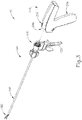
- FIGS. 1-3 show an exemplary ultrasonic surgical instrument (10) that is configured to be used in minimally invasive surgical procedures (e.g., via a trocar or other small diameter access port, etc.).
- instrument (10) is operable to cut tissue and seal or weld tissue (e.g., a blood vessel, etc.) substantially simultaneously.
- Instrument (10) of this example comprises a disposable assembly (100) and a reusable assembly (200). The distal portion of reusable assembly (200) is configured to removably receive the proximal portion of disposable assembly (100), as seen in FIGS. 2-3 , to form instrument (10).
- assemblies (100, 200) are coupled together to form instrument (10) before a surgical procedure, the assembled instrument (10) is used to perform the surgical procedure, and then assemblies (100, 200) are decoupled from each other for further processing.
- disposable assembly (100) is immediately disposed of while reusable assembly (200) is sterilized and otherwise processed for re-use.
- reusable assembly (200) may be sterilized in a conventional relatively low temperature, relatively low pressure, hydrogen peroxide sterilization process.
- reusable assembly (200) may be sterilized using any other suitable systems and techniques (e.g., autoclave, etc.).
- reusable assembly (200) may be sterilized and reused approximately 100 times.
- reusable assembly (200) may be subject to any other suitable life cycle.
- reusable assembly (200) may be disposed of after a single use, if desired.
- disposable assembly (100) is referred to herein as being "disposable,” it should be understood that, in some instances, disposable assembly (100) may also be sterilized and otherwise processed for re-use.
- disposable assembly (100) may be sterilized and reused approximately 2-30 times, using any suitable systems and techniques.
- disposable assembly (100) may be subject to any other suitable life cycle.
- disposable assembly (100) and/or reusable assembly (200) includes one or more features that are operable to track usage of the corresponding assembly (100, 200), and selectively restrict operability of the corresponding assembly (100, 200) based on use.
- disposable assembly (100) and/or reusable assembly (200) may include one or more counting sensors and a control logic (e.g., microprocessor, etc.) that is in communication with the counting sensor(s).
- the counting sensor(s) may be able to detect the number of times the ultrasonic transducer of instrument (10) is activated, the number of surgical procedures the corresponding assembly (100, 200) is used in, the number of trigger closures, and/or any other suitable conditions associated with use.
- the control logic may track data from the counting sensor(s) and compare the data to one or more threshold values. When the control logic determines that one or more threshold values have been exceeded, the control logic may execute a control algorithm to disable operability of one or more components in the corresponding assembly (100, 200). In instances where the control logic stores two or more threshold values (e.g., a first threshold for number of activations and a second threshold for number of surgical procedures, etc.), the control logic may disable operability of one or more components in the corresponding assembly (100, 200) the first time one of those thresholds is exceeded, or on some other basis.
- two or more threshold values e.g., a first threshold for number of activations and a second threshold for number of surgical procedures, etc.
- a control logic may also determine whether instrument (10) is currently being used in a surgical procedure, and refrain from disabling instrument (10) until that particular surgical procedure is complete. In other words, the control logic may allow the operator to complete the current surgical procedure but prevent instrument (10) from being used in a subsequent surgical procedure.
- Various suitable forms that counters or other sensors may take will be apparent to those of ordinary skill in the art in view of the teachings herein.
- Various suitable forms that a control logic may take will also be apparent to those of ordinary skill in the art in view of the teachings herein.
- instrument (10) may simply omit features that track and/or restrict the amount of usage of instrument (10).
- Disposable assembly (100) of the present example comprises a body portion (110), a shaft assembly (150) extending distally from body portion (110), and an end effector (180) located at the distal end of shaft assembly (150).
- end effector (180) of this example comprises a clamp arm (182) and an ultrasonic blade (190).
- Clamp arm (182) includes a clamp pad (184), which faces blade (190).
- clamp arm (182) is pivotable toward and away from blade (190) to selectively compress tissue between clamp pad (184) and blade (190).
- FIG. 1 As seen in FIG.
- blade (190) is an integral feature of the distal end of an acoustic waveguide (192), which extends coaxially through tubes (152, 170), and which is configured to communicate ultrasonic vibrations to blade (190) as will be described in greater detail below.
- Shaft assembly (150) comprises an outer tube (152) and an inner tube (170).
- Outer tube (152) is operable to translate longitudinally relative to inner tube (170) to selectively pivot clamp arm (182) toward and away from blade (190).
- integral pin features (186) of clamp arm (182) pivotally secure a first portion of clamp arm (182) to a distally projecting tongue (154) of outer tube (152); while an inserted pin (188) pivotally secures a second portion of clamp arm (182) to a distally projecting tongue (172) of inner tube (170).
- tubes (152, 170) cooperate to pivot clamp arm (182) toward blade (190) when outer tube (152) is retracted proximally relative to inner tube (170).
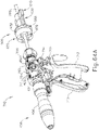
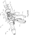
- clamp arm (182) may be pivoted back away from blade (190) (e.g., from the position shown in FIG. 6B to the position shown in FIG. 6A ) by translating outer tube (152) distally relative to inner tube (170), in reverse of the operation shown in FIGS. 6A-6B .
- clamp arm (182) may be pivoted toward blade (190) to grasp, compress, seal, and sever tissue captured between clamp pad (184) and blade (190).
- Clamp arm (182) may be pivoted away from blade (190) to release tissue from between clamp pad (184) and blade (190); and/or to perform blunt dissection of tissue engaging opposing outer surfaces of clamp arm (182) and blade (190).
- Reusable assembly (200) comprises various features that are operable to activate blade, including a battery and an ultrasonic transducer. Reusable assembly (200) further includes features that are operable to couple the ultrasonic transducer with waveguide to thereby couple the ultrasonic transducer with blade (190).
- the distal end of blade (190) is located at a position corresponding to an anti-node associated with resonant ultrasonic vibrations communicated through waveguide (192), in order to tune the acoustic assembly to a preferred resonant frequency f o when the acoustic assembly is not loaded by tissue.
- the distal end of blade (190) is configured to move longitudinally in the range of, for example, approximately 10 to 500 microns peak-to-peak, and in some instances in the range of about 20 to about 200 microns at a predetermined vibratory frequency f o of, for example, 55.5 kHz.
- f o a predetermined vibratory frequency
- the ultrasonic oscillation of blade (190) may simultaneously sever the tissue and denature the proteins in adjacent tissue cells, thereby providing a coagulative effect with relatively little thermal spread.
- an electrical current may also be provided through blade (190) and/or clamp pad (184) to also seal the tissue.
- disposable assembly (100) and/or reusable assembly (200) may be constructed and operable in accordance with at least some of the teachings of U.S. Pub. No. 2015/0245850, entitled “Ultrasonic Surgical Instrument with Removable Handle Assembly,” published September 3, 2015 ,
- disposable assembly (100) and/or reusable assembly (200) may be constructed and operable in accordance with at least some of the teachings of U.S. Pub. No.
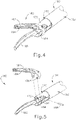
- FIGS. 8-11 show an exemplary alternative disposable assembly (500) that may be used with a variation of reusable assembly (200).
- disposable assembly (500) may incorporate the various details described above and/or details described in any of the various references that are cited herein. Other suitable details will be apparent to those of ordinary skill in the art in view of the teachings herein.
- Disposable assembly (500) of the present example comprises a first disposable sub-assembly (502) and a second disposable sub-assembly (504).
- Sub-assemblies (502, 504) are configured to be coupled together in order to form disposable assembly (500), which may then be coupled with a variation of reusable assembly (200) to form a complete ultrasonic surgical instrument.
- disposable assembly (500) may be removed from the variation of reusable assembly (200); and then first disposable sub-assembly (502) may be removed from second disposable sub-assembly (504).
- the variation of reusable assembly (200) may be cleaned, sterilized, and re-used up to 100 times (by way of example only).
- First disposable sub-assembly (502) may be disposed of, such that first disposable sub-assembly (502) is only used one single time.
- Second disposable sub-assembly (504) may be cleaned, sterilized, and re-used between 2 to 20 times (by way of example only).
- these re-use scenarios are merely illustrative examples. It should nevertheless be understood that the configuration of disposable assembly (500) may minimize the amount of single-use material that is disposed of after each surgical procedure. This may reduce cost and overall waste as compared to conventional instrumentation.
- first disposable sub-assembly (502) of the present example comprises an outer tube (580), a clamp arm (570), and a distal inner tube member (600).
- Clamp arm (570) is configured to form an end effector (550) with an ultrasonic blade (560), which is part of second disposable sub-assembly (504) as will be described in greater detail below.
- Clamp arm (570) is pivotably coupled with outer tube (580) and with distal inner tube member (600).
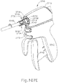
- Outer tube (580) is configured to translate longitudinally while distal inner tube member (600) remains stationary, which drives clamp arm (570) to pivot between an open position ( FIG. 10A ) and a closed position ( FIG. 10B ). In the closed position, clamp arm (570) is operable to clamp tissue against blade (560), which may then be ultrasonically activated to sever and/or seal the tissue as described herein and in various references cited herein.
- clamp arm (570) of the present example comprises a pair of pin openings (572), a clamp pad (574), and a pair of pivot studs (576).
- Pin openings (572) are configured to receive a pin (610), which is also disposed in a pin opening (602) of distal inner tube member (600).
- Clamp pad (574) of the present example comprises polytetrafluoroethylene (PTFE) and includes surface features (e.g., teeth or ridges, etc.) that are configured to promote gripping of tissue.
- PTFE polytetrafluoroethylene
- surface features e.g., teeth or ridges, etc.
- Pivot studs (576) are received in openings (586) of outer tube (580).
- Clamp arm (570) is pivotable about axes defined by pivot studs (576) and by pin (610), which enables clamp arm (570) to transition between the open position ( FIG. 10A ) and the closed position ( FIG. 10B ) in response to translation of outer tube (580) relative to distal inner tube member (600).
- distal inner tube member (600) of the present example comprises pin opening (602) and a pair of proximally projecting, resilient coupling arms (604).
- Each coupling arm (604) defines a laterally presented opening (606) and a proximally facing, obliquely angled bearing surface (607).
- each coupling arm (604) also flares outwardly.
- the proximal end of distal inner tube member (600) also includes a pair of proximally facing, obliquely angled bearing surfaces (608) that converge proximally at a proximal-most point. As best seen in FIG.
- distal inner tube member (600) further includes additional proximally facing, obliquely angled bearing surfaces (609).
- Bearing surfaces (607, 608, 609) are all oriented to generally provide a lead-in toward a gap (601) that is defined in the underside of distal inner tube member (600).
- This gap (601) is configured to accommodate longitudinal travel of the distal end of ultrasonic blade (560) during assembly of first disposable sub-assembly (502) with second disposable sub-assembly (504), as will be described in greater detail below.
- distal inner tube member (600) is configured to be removably secured to a proximal inner tube member (590) during assembly of first disposable sub-assembly (502) with second disposable sub-assembly (504).
- This coupling provides a longitudinal mechanical grounding for distal inner tube member (600), such that distal inner tube member (600) does not translate longitudinally relative to other components of disposable assembly (500) when inner tube members (590, 600) are coupled together.
- the distal end of outer tube (580) of the present example comprises openings (586) that pivotably receive pivot studs (576) as noted above.
- the distal end of outer tube (580) further includes a pair of elongate lateral openings (582) that are located proximal to openings (586). Openings (582) are angularly offset from each other by 180° about the longitudinal axis of outer tube (580).
- a tab (584) is located at the proximal end of each opening (586). Each tab (584) is directed inwardly and is substantially rigid.
- each tab (584) is rigid enough to not deform during disassembly of first disposable sub-assembly (502) from second disposable sub-assembly (504) as will be described in greater detail below.
- Outer tube (580) is slidably disposed about distal inner tube member (600), such that outer tube (580) is operable to translate longitudinally relative to distal inner tube member (600).
- the proximal end of outer tube (580) of the present example comprises a guide slot (620) and a pair of lateral openings (630).
- Guide slot (620) includes a first portion (622), a second portion (624), and a third portion (626).
- First and third portions (622, 626) extend longitudinally while second portion (624) extends helically.
- First and third portions (622, 626) are angularly offset from each other by approximately 90° about the longitudinal axis of outer tube (580).
- Guide slot (620) thus has a dogleg configuration in the present example.
- Other suitable forms that guide slot (620) may take will be apparent to those of ordinary skill in the art in view of the teachings herein.
- Each lateral opening (630) includes a respective pair of distal and proximal flange features (632) in the present example.
- outer tube (580) is configured to couple with a tube actuator (650) of second disposable sub-assembly (504) when first disposable sub-assembly (502) is coupled with second disposable sub-assembly (504).
- Tube actuator (650) is configured to drive outer tube (580) longitudinally, to thereby drive clamp arm (570) toward and away from blade (560) as described above.
- second disposable sub-assembly (504) of the present example comprises a partial handle assembly (510) having a pivoting trigger (512), a set of buttons (514, 516), a coupling feature (518), a communication feature (519), and a knob member (520).
- proximal inner tube member (590) extends distally from partial handle assembly (510).
- An acoustic waveguide (562) is coaxially disposed in proximal inner tube member (590) and distally terminates in ultrasonic blade (560).
- Waveguide (562) and blade (560) may be configured and operable just like waveguide (192) and blade (190) described above; and/or as described in any of the various references cited herein.
- Trigger (512) is operable to drive tube actuator (650) longitudinally, to thereby drive outer tube (580) longitudinally, to thereby drive clamp arm (570) toward and away from blade (560), when first disposable sub-assembly (502) is coupled with second disposable sub-assembly (504). Structural features of tube actuator (650) will be described in greater detail below. Various suitable components that may be used to provide longitudinal movement of tube actuator (650) in response to pivotal movement of trigger (512) will be apparent to those of ordinary skill in the art in view of the teachings herein. By way of example only, trigger (512) may be operatively coupled with tube actuator (650) in accordance with at least some of the teachings of U.S. Pub. No.
- trigger (512) may be operatively coupled with tube actuator (650) in accordance with at least some of the teachings of U.S. Pub. No. 2016/0015419, entitled “Ultrasonic Surgical Instrument with Removable Handle Assembly,” published January 21, 2016 ,
- buttons (514, 516) are operable to activate ultrasonic blade (560).
- buttons (514, 516) are operable to activate the ultrasonic transducer assembly in the variation of reusable assembly (200), which in turn generates ultrasonic vibrations, which are communicated along waveguide (562) to reach blade (560).
- button (514) activates ultrasonic blade (560) with ultrasonic energy at a first set of parameters (e.g., high power); while button (516) activates ultrasonic blade (560) with ultrasonic energy at a second set of parameters (e.g., low power).
- button (514) may activate ultrasonic blade (560) with ultrasonic energy; while button (516) activates end effector (550) to apply RF electrosurgical energy.
- button (514) may activate ultrasonic blade (560) with ultrasonic energy; while button (516) activates end effector (550) to apply RF electrosurgical energy.
- buttons (514, 516) may be configured, arranged, and operable will be apparent to those of ordinary skill in the art in view of the teachings herein.
- Coupling feature (518) is operable to couple with one or more complementary coupling features in the variation of reusable assembly (200) in accordance with at least some of the teachings of U.S. Pub. No. 2015/0245850 and/or in accordance with at least some of the teachings of U.S. Pub. No. 2016/0015419 .
- coupling feature (518) may be actuated to transition disposable assembly (500) into a cleaning mode in accordance with at least some of the teachings of U.S. Pub. No. 2015/0245850 and/or in accordance with at least some of the teachings of U.S. Pub. No. 2016/0015419 .
- Various suitable components, features, and operabilities that may be incorporated into and/or otherwise associated with coupling feature (518) will be apparent to those of ordinary skill in the art in view of the teachings herein.
- Communication feature (519) is operable to couple with one or more complementary coupling features in the variation of reusable assembly (200) in accordance with at least some of the teachings of U.S. Pub. No. 2015/0245850 and/or in accordance with at least some of the teachings of U.S. Pub. No. 2016/0015419 .
- communication feature (519) may comprise one or more electrical contacts that are operable to provide data communication and/or other electrical related operability when coupled with one or more complementary coupling features in the variation of reusable assembly (200).
- partial handle assembly (510) may include sensors and/or various other kinds of features from which data may be provided to the variation of reusable assembly (200) via communication feature (519).
- Various suitable components, features, and operabilities that may be incorporated into and/or otherwise associated with communication feature (519) will be apparent to those of ordinary skill in the art in view of the teachings herein.
- proximal inner tube member (590) is disposed coaxially about waveguide (562) yet is radially spaced apart from waveguide (562) such that inner tube member (590) does not contact waveguide (562).
- a seal member (640) is coaxially interposed between the distal end of proximal inner tube member (590) and waveguide (562).
- seal member (640) comprises a pair of inner ridges (642) and laterally positioned flats (644) that complement flats formed in waveguide (562).
- Seal member (640) is formed of an elastomeric material and is located on waveguide (562) at a longitudinal position corresponding to a node associated with resonant ultrasonic vibrations communicated through waveguide (562). Seal member (640) thus provides structural support between waveguide (562) and proximal inner tube member (590) without substantially interfering with ultrasonic vibrations through waveguide (562). Seal member (640) also prevents the ingress of fluids into the gap that is defined between proximal inner tube member (590) and waveguide (562).
- a series of elastomeric members may be interposed between proximal inner tube member (590) and waveguide (562), at longitudinal positions corresponding to a nodes associated with resonant ultrasonic vibrations communicated through waveguide (562), though such elastomeric members may be configured differently from seal member (640).
- Proximal inner tube member (590) also comprises a pair of integral, outwardly projecting studs (592) in this example. Studs (592) are configured to fit in openings (606) of distal inner tube member (600), to thereby couple inner tube members (590, 600) together as will be described in greater detail below.
- Knob member (520) is operable to rotate the shaft assembly that is formed by waveguide (562), inner tube portions (590, 600), outer tube (580), and end effector (550) when first disposable sub-assembly (502) is coupled with second disposable sub-assembly (504).
- this shaft assembly is rotatable relative to partial handle assembly (510).
- knob member (520) includes a pair of cantilevered buttons (522).
- Each cantilevered button (522) includes an inwardly projecting prong (524).
- Buttons (522) are operable to be pressed inwardly to thereby drive prongs (524) inwardly, though buttons (522) are resiliently biased to maintain the position of prongs (524) as shown in FIG. 29 .
- a guide pin (526) projects inwardly within a bore (528) defined in knob member (520).
- Guide pin (526) is fixedly secured in knob member (520) and is configured to interact with guide slot (620) of outer tube (580) during assembly and disassembly of sub-assemblies (502, 504) as will be described in greater detail below.
- tube actuator (650) is configured to removably couple with outer tube (580) and thereby drive outer tube (580) longitudinally in response to pivotal motion of trigger (512).
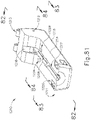
- tube actuator (650) comprises a pair of distally projecting arms (654).
- Each arm (654) includes an outwardly projecting prong (656).
- Each prong (656) has chamfered distal and proximal edges, which promote entry and exit of prongs (656) into and out of corresponding openings (630) of outer tube (580) during assembly and disassembly of sub-assemblies (502, 504) as will be described in greater detail below.
- Arms (654) are resiliently biased to assume a parallel relationship with each other as shown in FIG. 31 . However, arms (654) are configured to deform inwardly to enable entry and exit of prongs (656) into and out of corresponding openings (630) of outer tube (580) during assembly and disassembly of sub-assemblies (502, 504) as will be described in greater detail below.
- FIGS. 33A-34F show various stages of assembling first disposable sub-assembly (502) with second disposable sub-assembly (504).
- FIGS. 33A-33D show various stages occurring at the proximal end of first disposable sub-assembly (502) during a process of assembling first disposable sub-assembly (502) with second disposable sub-assembly (504); while FIGS. 34A-34F show various stages occurring at the proximal end of first disposable sub-assembly (502) during a process of assembling first disposable sub-assembly (502) with second disposable sub-assembly (504).
- FIG. 32 shows the same initial stage of assembly as is shown in FIG. 33A .
- knob member (522) is omitted from FIGS. 33A-33D in order to enable visualization of the components that would otherwise be obscured by knob member (522).
- an operator may grasp first disposable sub-assembly (502) in one hand, grasp second disposable sub-assembly (504) in the other hand, and then move first disposable sub-assembly (502) relative to second disposable sub-assembly (504) (while holding knob member (520) stationary) in order to accomplish the process.
- first disposable sub-assembly (502) in one hand
- grasp second disposable sub-assembly (504) grasp second disposable sub-assembly (504) in the other hand, and then move first disposable sub-assembly (502) relative to second disposable sub-assembly (504) (while holding knob member (520) stationary) in order to accomplish the process.
- first disposable sub-assembly (502) is at a distal position.
- the proximal end of outer tube (580) is distal to guide pin (526).
- FIG. 33A also shows how the proximal end of proximal inner tube member (590) includes longitudinally extending slots (594) that accommodates inwardly projecting features of second disposable sub-assembly (504), such as guide pin (526) and the distal ends of arms (654).
- FIG. 33B shows a stage where first disposable sub-assembly (502) has been translated proximally to a point where guide pin (526) has traversed first portion (622) of guide channel (620) in outer tube (580).
- features at the distal ends of sub-assemblies (502, 504) may provide the angular alignment of first disposable sub-assembly (502) relative to second disposable sub-assembly (504) that would be required in order for guide pin (526) to successfully enter first portion (622) of guide channel (620) during the transition to the state shown in FIG. 33B .
- interaction between the distal end of blade (560) and one or more bearing surfaces (607, 608, 609) of distal inner tube member (600) may ensure that first disposable sub-assembly (502) has an appropriate angular alignment relative to second disposable sub-assembly (504) in order for guide pin (526) to successfully enter first portion (622) of guide channel (620) during the transition to the state shown in FIG. 33B .
- openings (630) area still distal to prongs (656).
- FIG. 33C shows a stage where first disposable sub-assembly (502) has been translated proximally and rotated about the longitudinal axis to a point where guide pin (526) has traversed second portion (624) of guide channel (620) in outer tube (580).
- first disposable sub-assembly (502) has rotated 90° relative to second disposable sub-assembly (504), about the longitudinal axis of outer tube (580).
- openings (630) area still distal to prongs (656).
- the flared proximal end of outer tube (580) has just engaged the distal edges of prongs (656).
- FIG. 33D shows a stage where first disposable sub-assembly (502) has been translated proximally to a point where guide pin (526) has traversed third portion (626) of guide channel (620) in outer tube (580).
- the proximal end of outer tube (580) has deflected the distal ends of arms (654) inwardly, thereby driving prongs (656) inwardly.
- this deflection is accommodated by longitudinally extending slots (594) of proximal inner tube member (590).
- outer tube (580) When outer tube (580) reaches the longitudinal position where prongs (656) are aligned with openings, the resilience of arms (654) drives prongs (656) outwardly such that prongs (656) snap into place in openings (630).
- outer tube (580) is coupled with tube actuator (650) such that outer tube (580) will translate longitudinally with tube actuator (650).
- Flange features (632) reinforce the coupling between prongs (656) and the edges of openings (630).
- third portion (626) is dimensioned to enable outer tube (580) to translate relative to guide pin (526) during the translation of outer tube (580) that would be required to pivot clamp arm (570) toward and away from blade (560) as described above.
- Third portion (626) is also dimensioned to provide enough clearance for knob member (520) and guide pin (526) to be translated distally relative to outer tube (580) to initiate disassembly of first disposable sub-assembly (502) from second disposable sub-assembly (504) as described in greater detail below.
- first disposable sub-assembly (502) appears to remain fixed in place while second disposable sub-assembly (504) moves.
- second disposable sub-assembly (504) may in fact hold stationary and move first disposable sub-assembly (502) in order to transition through the stages shown in FIGS. 34A-34G.
- sub-assemblies (502, 504) are initially positioned such that the curved distal tip of blade (560) is oriented downwardly as outer tube (580) is slid proximally along blade (560), waveguide (562), and proximal inner tube portion (590). This angular positioning may be the same as that shown in FIGS. 33A-33B .
- first disposable sub-assembly (502) In the event that outer tube (580) is slid proximally along blade (560), waveguide (562), and proximal inner tube portion (590) at a different angular orientation, the distal end of blade (560) will eventually engage one or more bearing surfaces (607, 608, 609).
- a camming engagement between the distal end of blade (560) and the one or more bearing surfaces (607, 608, 609) will urge first disposable sub-assembly (502) to rotate about the longitudinal axis of outer tube (580) until the angular relationship shown in FIGS. 33A-33B and 34A-34C is achieved.
- studs (592) of proximal inner tube member (590) are oriented along an axis that is perpendicular to an axis passing through the centers of openings (582) of outer tube (580).
- first disposable sub-assembly (502) translates proximally through the range of motion where guide pin (526) traverses second portion (624) of guide channel (620), the engagement between guide pin (526) and guide channel (620) causes first disposable sub-assembly (502) to rotate 90° about the longitudinal axis of outer tube (580) as noted above. This rotation is also shown in FIG. 34D .
- studs (592) of proximal inner tube member (590) are oriented along an axis that is parallel to an axis passing through the centers of openings (582) of outer tube (580).
- blade (560) is now at the orientation shown in FIGS. 8-9 , such that the laterally oriented curve of blade (560) complements the laterally oriented curve of clamp arm (570).
- first disposable sub-assembly (502) proximally relative to second disposable sub-assembly (504)
- studs (592) of proximal inner tube member (590) engage bearing surfaces (607) of arms (604) of distal inner tube member (600).
- this engagement causes the proximal ends of arms (604) to deflect outwardly as shown in FIG. 34E .
- Openings (582) of outer tube (580) accommodate this deflection.
- first disposable sub-assembly (502) proximally relative to second disposable sub-assembly (504)
- studs (592) eventually reach openings (606) in arms (504).
- the resilience of arms (504) drives the proximal ends of arms (504) back inwardly, such that studs (592) snap into place in openings (606) as shown in FIG. 34F .
- sub-assemblies (502, 504) are coupled together such that disposable assembly (500) is ready for assembly with the variation of reusable assembly (200). It should be understood that the state shown in FIG. 34F corresponds with the state shown in FIG. 33D .
- first disposable sub-assembly (502) may be configured for just one single use while second disposable sub-assembly (504) may be configured for 2 to 20 uses (or any other suitable number of uses). It may therefore be desirable to enable an operator to disassemble first disposable sub-assembly (502) from second disposable sub-assembly (504) without destroying second disposable sub-assembly (504).
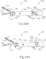
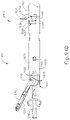
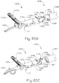
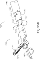
- FIGS. 35A-36B show various stages of disassembling first disposable sub-assembly (502) with second disposable sub-assembly (504). In particular, FIGS.
- 35A-35E show various stages occurring at the proximal end of first disposable sub-assembly (502) during a process of disassembling first disposable sub-assembly (502) from second disposable sub-assembly (504); while FIGS. 36A-36B show various stages occurring at the proximal end of first disposable sub-assembly (502) during a process of disassembling first disposable sub-assembly (502) from second disposable sub-assembly (504).
- prongs (524) of knob member (520) are initially located at positions that are proximal in relation to the positions of prongs (656) of tube actuator (650). This longitudinal offset may prevent an operator from inadvertently disengaging prongs (656) from outer tube (580) during use of disposable assembly (500) in a fully assembled instrument.
- the operator may need to first translate knob member (520) distally relative to the other components, as shown in FIG. 35B .
- knob member (520) is resiliently biased to maintain the proximal positioning as shown in FIG. 35A . Once knob member (520) has been translated distally to the position shown in FIG.
- prongs (524) of knob member (520) are aligned with prongs (656) of tube actuator (650), though prongs (524) of knob member (520) are laterally spaced form prongs (656) of tube actuator (650).
- knob member (520) is not translatable, such that prongs (524) of knob member (520) are aligned with prongs (656) of tube actuator (650) during normal use of disposable assembly (500) in a fully assembled instrument.
- buttons (522) are pressed inwardly simultaneously.
- prongs (524) bear against prongs (656), thereby deflecting the distal ends of arms (654) inwardly. This deflection at least partially unseats prongs (656) from openings (630) in outer tube (580).
- prongs (656) at least partially unseated from openings (630) in outer tube (580) the operator may pull distally on first disposable sub-assembly (502) while holding second disposable sub-assembly (504) stationary (while still pressing cantilevered buttons (522) inwardly). This will ultimately result in the proximal end of outer tube (580) clearing prongs (524) of tube actuator as shown in FIG. 35D . As noted above, the cantilevered edges of prongs (524) may further promote this clearing. With outer tube (580) clear of prongs (524), arms (654) may resiliently transition back to the straight, parallel orientations as shown in FIG. 35D .
- first disposable sub-assembly (502) clear from the remainder of second disposable sub-assembly (504).
- the operator may then dispose of first disposable sub-assembly (502); and clean, sterilize, and re-use second disposable sub-assembly (504) if appropriate.
- first disposable sub-assembly (502) may rotate relative to second disposable sub-assembly (504), about the longitudinal axis of outer tube (580), due to interaction between guide pin (526) and guide slot (620) as described above.
- distal inner tube member (600) is longitudinally secured to proximal inner tube member (590) via arms (604) and studs (592), there will be some degree of relative movement between outer tube member (580) and distal inner tube member (600) during the disassembly of first disposable sub-assembly (502) from second disposable sub-assembly (504). This relative movement is shown in FIGS. 36A-36B .
- the inwardly directed tabs (584) of outer tube (580) will eventually engage bearing surfaces (607) of arms (604).
- This disengagement of studs (592) from arms (604) will decouple distal inner tube member (600) from proximal inner tube member (590), thereby enabling distal inner tube member (600) to travel distally with outer tube (580) as the operator continues to pull outer tube (580) distally to complete the disassembly of first disposable sub-assembly (502) from second disposable sub-assembly (504).
- first disposable sub-assembly (502, 1502) with second disposable sub-assembly (504, 1504) may be utilized to properly couple ultrasonic blade (560, 1560) with reusable assembly (200).
- ultrasonic blade (560, 1560) with reusable assembly (200) may save time and simplify the assembly process.
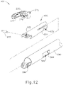
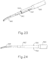
- FIGS. 37-38 show an exemplary alternative disposable assembly (700) that is coupled to alternative reusable assembly (400).
- disposable assembly (700) may incorporate the various details described above and/or details described in any of the various references that are cited herein. Other suitable details will be apparent to those of ordinary skill in the art in view of the teachings herein.
- reusable assembly (400) may be substantially similar to reusable assembly (200) described above, with differences described below. Therefore, reusable assembly (400) comprises various features that are operable to activate an ultrasonic blade (760), including an ultrasonic transducer (406).
- Reusable assembly (400) may include a battery or may be connected to a generator via wires in order to activate ultrasonic transducer (406).
- reusable assembly (400) includes a coupling shaft (404) rotationally fixed to a distally extending threaded stud (402) of transducer (406).
- reusable assembly (400) may be rotated relative to disposable assembly (700) in order to couple disposable assembly (700) with reusable assembly (400).
- Disposable assembly (700) of the present example comprises a first disposable sub-assembly (702) and a second disposable sub-assembly (704).
- Sub-assemblies (702, 704) are configured to be coupled together in order to form disposable assembly (700), which may then be coupled with a variation of reusable assembly (400) for form a complete ultrasonic surgical instrument.
- disposable assembly (700) may be removed from the variation of reusable assembly (400); and then first disposable sub-assembly (702) may be removed from second disposable sub-assembly (704).
- the variation of reusable assembly (400) may be cleaned, sterilized, and re-used up to 100 times (by way of example only).
- First disposable sub-assembly (702) may be disposed of, such that first disposable sub-assembly (702) is only used one single time.
- Second disposable sub-assembly (704) may be cleaned, sterilized, and re-used between 2 to 20 times (by way of example only).
- these re-use scenarios are merely illustrative examples. It should nevertheless be understood that the configuration of disposable assembly (700) may minimize the amount of single-use material that is disposed of after each surgical procedure. This may reduce cost and overall waste as compared to conventional instrumentation.
- first disposable sub-assembly (702) of the present example comprises an outer tube (780), a clamp arm (770), and a distal inner tube member (800).
- Clamp arm (770) is configured to form an end effector (750), as shown in FIG. 39 , with an ultrasonic blade (760), which is part of second disposable sub-assembly (704) as will be described in greater detail below.
- Clamp arm (770) is pivotably coupled with outer tube (780) and with distal inner tube member (800).
- Outer tube (780) is configured to translate longitudinally while distal inner tube member (800) remains stationary, which drives clamp arm (770) to pivot between an open position and a closed position. In the closed position, clamp arm (770) is operable to clamp tissue against blade (760), which may then be ultrasonically activated to sever and/or seal the tissue as described herein and in various references cited herein.
- clamp arm (770) of the present example comprises a pair of pin openings (772), a clamp pad (774), and a pair of pivot studs (776).
- Pin openings (772) are configured to receive a pin (810), which is also disposed in a pin opening (802) of distal inner tube member (800).
- Clamp pad (774) of the present example comprises polytetrafluoroethylene (PTFE) and includes surface features (e.g., teeth or ridges, etc.) that are configured to promote gripping of tissue.
- PTFE polytetrafluoroethylene
- surface features e.g., teeth or ridges, etc.
- Pivot studs (776) are received in openings (786) of outer tube (780).
- Clamp arm (770) is pivotable about axes defined by pivot studs (776) and by pin (810), which enables clamp arm (770) to transition between the open position and the closed position in response to translation of outer tube (780) relative to distal inner tube member (800).
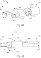
- distal inner tube (800) of the present example comprises a distal portion (803) defining a pair of lateral openings (812), a pair of proximally presented tabs (812), a proximal portion (801), pin opening (802), and a circumferential tab (804) extending into a flat member (806) terminating into an outwardly extending lip (807).
- Circumferential tab (804) and flat member (806) are resiliently flexible and are in a relaxed position as shown in FIGS. 40-43 .
- Each proximally presented tab (812) extends inwardly from a respective lateral opening (812).
- Flat member (806) defines a slot (808). As best seen in FIG.
- proximal portion (801) defines a pathway (816) extending words circumferential tab (805) and flat member (806).
- a gap (805) extends from proximal portion (801) through distal portion (803). This gap (805) is configured to accommodate longitudinal travel of the distal end of ultrasonic blade (760) during assembly of first disposable sub-assembly (602) with second disposable sub-assembly (604), as will be described in greater detail below.
- distal inner tube member (800) is configured to be removably secured to a proximal inner tube member (790) during assembly of first disposable sub-assembly (702) with second disposable sub-assembly (704).
- This coupling provides a longitudinal mechanical grounding for distal inner tube member (800), such that distal inner tube member (800) does not translate longitudinally relative to other components of disposable assembly (700) when inner tube members (790, 800) are coupled together.
- the distal end of outer tube (780) of the present example comprises openings (786) that pivotally receive pivot studs (776) as noted above.
- the distal end of outer tube (780) further includes an elongate lateral opening (782) that is located proximal to openings (786).
- Outer tube (780) is slidably disposed about distal inner tube member (800), such that outer tube (780) is operable to translate longitudinally relative to distal inner tube member (800).
- the proximal end of outer tube (780) of the present example comprises a coupling feature (820).
- Coupling feature (820) comprises an overmolded portion (822) fixed relative to the rest of outer tube (780), a guide projection (826) extending radially from overmolded portion (822), a pair of proximally presented sleeves (828) spaced 180° relative from each other, and a pair resilient tabs (830) extending proximally relative to overmolded portion (822) and between proximally presented sleeves (828).
- Overmolded portion (822) defines a pair of notches (824) presented in the distal direction.
- notches (824) are dimensioned to mate with an end of assembly tool (900) to promote attaching coupling feature (820) to a tube actuator (850) of second disposable sub-assembly (704).
- Each resilient tab (830) includes an outwardly extending protrusion (832).
- Each outwardly extending protrusion (832) includes a sloped assembly surface (834), a sloped disassembly surface (838) and a locking surface (836).
- sloped assembly surface (834) is configured to promote deflection of resilient tabs (830) during assembly of coupling feature (820) with tube actuator (850)
- sloped disassembly surface (836) is configured to promote deflection of resilient tabs (830) during disassembly of coupling feature (820) with tube actuator (850)
- locking surface (836) is configured to promote unitary translation of coupling feature (820) with tube actuator (850).
- outer tube (780) is configured to couple with a tube actuator (850) of second disposable sub-assembly (704) when first disposable sub-assembly (702) is coupled with second disposable sub-assembly (704).
- Tube actuator (850) is configured to drive outer tube (780) longitudinally, to thereby drive clamp arm (770) toward and away from blade (760) as described above.
- second disposable sub-assembly (704) of the present example comprises a handle assembly (510) having body (711), a pistol grip (713), a pivoting trigger (712) pivotally coupled to the body (711) and pistol grip (713), and a set of buttons (714, 716).
- Body (711) defines an opening (718) configured to selectively receive reusable assembly (400), as will be described in greater detail below.
- proximal inner tube member (790) extends distally from handle assembly (710).
- An acoustic waveguide (762) is coaxially disposed in proximal inner tube member (790) and distally terminates into ultrasonic blade (760). Waveguide (762) and blade (760) may be configured and operable just like waveguide (192, 592) and blade (190, 590) described above; and/or as described in any of the various references cited herein.
- Pistol grip (713) is operable to be grasped by an operator while trigger (712) is operable to drive tube actuator (850) longitudinally in response to pivoting trigger (712) toward and away from pistol grip (713). Pivoting trigger (712) toward and away pistol grip (713) thereby drives outer tube (780) longitudinally, to thereby drive clamp arm (770) toward and away from blade (760), when first disposable sub-assembly (702) is coupled with second disposable sub-assembly (704). Structural features of tube actuator (850) will be described in greater detail below.
- trigger (712) may be operatively coupled with tube actuator (850) in accordance with at least some of the teachings of U.S. Pub. No. 2015/0245850, entitled “Ultrasonic Surgical Instrument with Removable Handle Assembly,” published September 3, 2015 , .
- trigger (712) may be operatively coupled with tube actuator (850) in accordance with at least some of the teachings of U.S. Patent Pub. No. 2016/0015419, entitled “Ultrasonic Surgical Instrument with Removable Handle Assembly,” Published January 21, 2016 , .
- buttons (714, 716) are operable to activate ultrasonic blade (760).
- buttons (714, 716) are operable to activate the ultrasonic transducer (406) in the variation of reusable assembly (400), which in turn generates ultrasonic vibrations, which are communicated along waveguide (762) to reach blade (760).
- button (714) activates ultrasonic blade (760) with ultrasonic energy at a first set of parameters (e.g., high power); while button (716) activates ultrasonic blade (760) with ultrasonic energy at a second set of parameters (e.g., low power).
- button (714) may activate ultrasonic blade (760) with ultrasonic energy; while button (716) activates end effector (750) to apply RF electrosurgical energy.
- button (714) may activate ultrasonic blade (760) with ultrasonic energy; while button (716) activates end effector (750) to apply RF electrosurgical energy.
- buttons (714, 716) may be configured, arranged, and operable will be apparent to those of ordinary skill in the art in view of the teachings herein.
- proximal inner tube member (790) is disposed coaxially about waveguide (762) yet is radially spaced apart from waveguide (762) such that inner tube member (790) does not contact waveguide (762).
- a seal member (840) is disposed around waveguide (792) just distal relative to proximal inner tube member (590).
- seal member is configured to interact with proximally presented tabs (814) of distal inner tube (800) to promote correct lateral alignment of distal inner tube (800) relative to waveguide (762).
- Seal member (840) may have any suitable geometry known to know in the art in view of the teachings herein.
- seal member (840) may be substantially like seal member (640) described above.
- Seal member (840) is formed of an elastomeric material and is located on waveguide (762) at a longitudinal position corresponding to a node associated with resonant ultrasonic vibrations communicated through waveguide (762).
- Seal member (840) thus provides structural support between waveguide (762) and proximal inner tube member (790) without substantially interfering with ultrasonic vibrations through waveguide (762).
- Seal member (840) also prevents the ingress of fluids into the gap that is defined between proximal inner tube member (790) and waveguide (762).
- a series of elastomeric members may be interposed between proximal inner tube member (790) and waveguide (762), at longitudinal positions corresponding to a nodes associated with resonant ultrasonic vibrations communicated through waveguide (762), though such elastomeric members may be configured differently from seal member (840).
- proximal inner tube member (790) comprises a longitudinally extending flat surface (796) extending adjacent to a longitudinally extending arched surface (798). The distal end of arched surface (797) terminates into a chamfered distal end (797).
- Proximal inner tube member (790) also comprises an integral, outwardly projecting stud (792) extending away from flat surface (796). Stud (792) is configured to fit in slot (808) of distal inner tube member (800), to thereby couple inner tube members (790, 800) together as will be described in greater detail below.
- Knob member (720) is operable to rotate the shaft assembly that is formed by waveguide (762), inner tube portions (790, 800), outer tube (780), and end effector (750) when first disposable sub-assembly (702) is coupled with second disposable sub-assembly (704).
- this shaft assembly is rotatable relative to handle assembly (710).
- knob member (720), proximal inner tube member (790), and waveguide (762) each include a pin hole (722, 791, 766) respectively to receive pin (705) while tube actuator (850) includes a pair of translation slots (852) to receive pin (705).
- knob member (720) rotates waveguide (762), proximal inner tube member (790), and tube actuator (850) unitarily.
- the dimension of translation slots (852) promotes translation of tube actuator (850) and outer tube (780) relative to knob member (720) when first disposable sub-assembly (702) is connected to second disposable sub-assembly (704).
- knob member (720) includes a distal face (724) defining a keyway (726) extending into knob member (720). Keyway (726) terminates into a rotating path (728). Rotating path (728) increases the inner diameter of knob member (720) for a selected circumferential portion of knob member (720). As will be described in greater detail below, keyway (726) and rotating path (728) are dimensioned to accept guide projection (826) of coupling feature (820) such that outer tube (780) may only couple with tube actuator (850) in one angular orientation about the longitudinal axis. Knob member (720) also includes a pair of guide tabs (730).
- guide tabs (730) may help promote proper lateral alignment of outer tube (780) relative to tube actuator (850). It should be understood that guide tabs (730) are merely optional. Some versions of knob member (720) may omit guide tabs (730).
- tube actuator (850) includes translation slot (852), a first pair of coupling windows (854), and a second pair of coupling windows (856).
- first pair of coupling windows are configured to promote coupling between tube actuator (850) and outer tube (780).
- Second coupling windows (856) may be used to promote coupling of tube actuator (850) with various suitable components that may be used to provide longitudinal movement of tube actuator (850) in response to pivotal movement of trigger (712).
- coupling windows (856) are currently shown to promote coupling of tube actuator (850) with various suitable components that may be used to provide longitudinal movement of tube actuator (850) in response to pivotal movement of trigger (712), a threaded portion or any other suitable coupling mechanism may be used as would be apparent to one having ordinary skill in the art in view of the teachings herein.
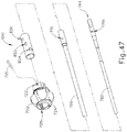
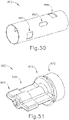
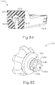
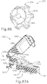
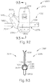
- FIGS. 51-54 show an exemplary assembly tool (900) that may be utilized to couple first disposable sub-assembly (702) with second disposable sub-assembly (704); and also to couple second disposable sub-assembly (704) with reusable assembly (400).
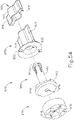
- Assembly tool (900) includes a spanner wrench portion (910), a hand grip portion (930), a torque slip portion (950), and a knob grip portion (970).
- Spanner wrench portion (910) and knob grip portion (970) are located on opposite ends of assembly tool (900).
- Spanner wrench portion (910), hand grip portion (930), torque slip portion (950), and knob grip portion (970) each define a pathway (918, 938, 958, 978) respectively.
- Assembly tool (900) is dimensioned such that distal end of outer tube (780) may be inserted through pathway (918, 938, 958, 978). As will be described in greater detail below, assembly tool (900) may be inserted to abut against coupling feature (820) or knob member (720), depending on whether spanner wrench portion (910) or knob grip portion (970) is inserted over distal end of outer tube (780) first.
- spanner wrench portion (910) includes a pair of prongs (912) extending distally from a central body (915), and a pair of wings (914) extending laterally from central body (915).
- central body (915) and wings (914) define a cavity (916) dimensioned to be inserted over hand grip portion (930).
- Cavity (916) may be dimensioned such that spanner wrench portion (910) is coupled to hand grip portion (930) with an interference fit.
- any other suitable method of coupling spanner wrench portion (910) with hand grip portion (930) may be utilized as would be apparent to one having ordinary skill in the art in view of the teachings herein, such as adhesives.
- spanner wrench portion (910) also defines a pathway (918) for receiving the distal end of outer tube (780).
- Hand grip portion (930) includes a central body portion (935) with a pair of grips (934) laterally extending from central body portion (935), and a pair of contact protrusions (932).
- Contact protrusions (932) are dimensioned to face towards torque slip portion (950).
- Torque slip portion (950) includes a disc member (952) unitarily connected to a shaft member (953).
- Disc member includes a circular pattern of flat surfaces (954), sloped surfaces (956), and vertical surfaces (959).
- Shaft member (953) includes a plurality of resilient tabs (953).
- Shaft member (953) is dimensioned to fit within pathway (938) of hand grip portion (930).
- resilient tabs (953) are configured to abut against the inner circumference of pathway (938) in order to provide a predetermined biasing force such that contact protrusions (932) are encouraged to abut against flat surfaces (954) and sloped surfaces (956) of disc member (952). While in the current example, resilient tabs (953) are used to provide a biasing force, any other suitable means of providing a biasing force may be used as would be apparent to one having ordinary skill in the art, such as springs.
- Knob gripping portion (970) defines pathway (978) and a gripping surface (976). Gripping surface (976) is dimensioned to cover the surface of knob member (720) such that knob member (720) is rotationally fixed to knob gripping portion (970). Additionally, knob gripping portion (970) is unitary connected to torque slip portion (950).
- Torque slip portion (950) is rotatably disposed within hand grip portion (930). However, the biasing force encouraging contact between contact protrusions (932) and surfaces (954, 956) promotes a predetermined frictional braking force.
- the frictional braking force between torque slip portion (950) and hand grip portion (930) may be great enough to encourage hand grip portion (930) and torque slip portion (950) to rotate unitarily.
- torque slip portion (950) may slip relative to hand grip portion (930) if assembly tool (900) experiences a force great enough to overcome the frictional braking force, such as a predetermined amount of torque.
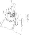
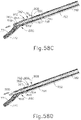
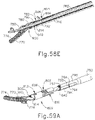
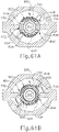
- FIGS. 55A-60B show various stages of assembling first disposable sub-assembly (702) with second disposable sub-assembly (704).
- FIGS. 55A-57B show various stages occurring at the proximal end of first disposable sub-assembly (702) with second disposable sub-assembly (704); while FIGS. 58A-59C show various stages occurring at the distal end of first deposable sub-assembly (702) during a process of assembling first disposable sub-assembly (702) with second disposable sub-assembly (704).
- FIGS. 60A-60B show how assembly tool (900) may be utilized to install first disposable sub-assembly (702) with second disposable sub-assembly (704).
- first disposable sub-assembly (702) in one hand, grasp second disposable sub-assembly (704) in the other hand, and then move first disposable sub-assembly (702) relative to second disposable sub-assembly (704) (while holding knob member (720) stationary) in order to accomplish the process.
- an operator may insert assembly tool (900), spanner wrench portion (910) first, over the distal end of first disposable sub-assembly (702) and manipulate first disposable sub-assembly (702) with assembly tool (900)
- FIGS. 55A-55B show the same movement as shown in FIGS. 56A-56C .
- knob member (720) is omitted from FIGS. 56A-56D in order to enable visualization of the components that would otherwise be obscured by knob member (720).
- FIGS. 55A-55B show that as the proximal end of outer tube (780) is being inserted within knob member (720), keyway (726) and guide projection (826) must be aligned so that coupling feature (820) may be inserted into knob member (720).
- first disposable sub-assembly (7020 is at a distal position. At this stage, the proximal end of outer tube (780) is distal relative to the distal end of tube actuator (850).
- the proximal end of outer tube (780) may be advanced proximally such that the proximal end of resilient tabs (830) and proximally presented sleeves (828) initially enter the distal end of tube actuator (850).
- outwardly extending protrusions (832) are not within tub actuator (850). Additionally, it should be understood that outwardly extending protrusions (832) are dimensioned to radially extend past the diameter of tube actuator (850) when resilient tabs (830) are in a relaxed position.
- the proximal end of outer tube (780) may be further advanced in the proximal direction such that proximally presented sleeves (828) and resilient tabs (830) are within the confines of tube actuator (850).
- proximally presented sleeves (828) and resilient tabs (830) are within the confines of tube actuator (850).
- the distal edge of tube actuator (850) abuts against sloped assembly surface (834) of outwardly extending protrusions (832) to drive resilient tabs (830) from a relaxed position to an inwardly flexed position.
- the inner diameter of tube actuator (850) makes contact with outwardly extending protrusions (832) to keep resilient tabs (930) in the inwardly flexed position.
- an operator may then rotate outer tube (780) in the clockwise direction (facing proximally) such that proximally presented sleeves (828) and resilient tabs (830) rotate within the confines of tube actuator (850).
- An operator may rotate outer tube (780) until outwardly extending protrusions (832) align with first coupling windows (854).
- outwardly extending protrusions (832) align with first coupling windows (854) the inner diameter of tube actuator (850) no longer makes contact with outwardly extending protrusions (832). Therefore, there is no external force keeping tabs (830) in the inwardly flexed position and the resilient nature of tabs (830) returns tabs (830) to the relaxed position.
- outwardly extending protrusions (832) radially extend past the diameter of tube actuator (850).
- locking surface (836) and sloped disassembly surfaces (838) may makes contact with a perimeter of first coupling window (854) such that the resilient nature of tabs (830) causes contact between surfaces (836, 838) and perimeter of first coupling window (854), to provide an interface fit between outer tube (780) and tube actuator (850).
- This inference fit may allow for selectively coupling outer tube (780) and tube actuator (850) such that unitary longitudinal translation of tube actuator (850) and outer tube (780) are achieved.
- first coupling window (854) may be dimensioned to contact portions of locking surface (836) and sloped assembly surface (834) when coupling tube actuator (850) and outer tube (780).
- FIGS. 57A-57B show that once outer tube (780) is inserted such that guide projection (826) is inserted within keyway (726) of knob member (720) as shown in FIGS. 55B , 56C , and 57A , rotating path (728) restricts rotation of outer tube (780) to a single direction due to interaction between guide projection (826) and rotating path (728). This may help ensure that end effector (750) is has proper rotational alignment when first disposable sub-assembly (702) is coupled with second disposable sub-assembly (704).
- guide tabs (730) are dimensioned to ensure proper lateral alignment as tube actuator (850) longitudinally translates outwardly extending protrusions (832) past guide tabs (730). This may help ensure that blade (760) has proper lateral alignment compared to clamp arm (770) as clamp arm (770) rotates toward and away from blade (760).
- guide tabs (730) are merely optional. Guide tabs (730) are omitted in some versions.
- first disposable sub-assembly (702) appears to remain fixed in place while second disposable sub-assembly (704) moves.
- second disposable sub-assembly (704) may in fact hold second disposable sub-assembly (704) stationary and move first disposable sub-assembly (702) in order to transition through the stages shown in FIGS. 58A-58E .
- FIGS. 59A-59C show coupling of distal inner tube (800) with proximal inner tube member (790) without outer tube (780) for purposes of clarity.
- sub-assemblies (702, 704) are initially positioned such that the curved distal tip of blade (760) is oriented downwardly as outer tube (780) is slid proximally along blade (760), waveguide (762), and proximal inner tube portion (790). This angular positioning may be the same as that shown in FIGS. 56A-56C .
- first disposable sub-assembly (702) in the proximal direction to the position shown in FIG. 58B so that blade (760) is inserted within gap (805).
- flat member (806) is directly adjacent to chamfered distal end (797) of arched surface (798).
- chamfered distal end (797) is dimensioned such that further proximal movement of disposable assembly (702) causes flat member (806) to deform outwardly relative to the relaxed position of flat member (806). This deformation is due to contact with arched surface (798).
- An operator may then further slide first disposable assembly (702) proximally to the position shown in FIGS.
- FIGS. 81D and 82B correlates with the position shown in FIGS. 55B and 79C.
- flat member (806) is still in an outwardly deformed position due to contact with arched surface (798).
- proximally presented tabs (814) are both in contact with seal member (840).
- seal member (840) is elastomeric. Seal member (840) in contact with proximally presented tabs (814) may promote lateral and vertical alignment of distal inner tube (800) relative to waveguide (762).
- first disposable assembly (702) relative to second disposable assembly (704) to the position shown in FIGS. 58E and 59C , such that flat member (806) is adjacent to flat surface (796).
- Flat member (806) returns to the relaxed position due to the dimensions of flat surface (796) compared to arched surface (798).
- slot (808) is longitudinally aligned with stud (792) such that rotation, from the position shown in FIGS. 58D to 58E and 59B to 59C , snaps stud (792) into slot (808).
- Outwardly extending lip (807) of flat member (806) may interface with camming surface (794) of stud (792) in order to promote stud (792) to snap into slot (808).
- Stud (792) and slot (808) are dimensioned such that proximal inner tube (790) and distal inner tube (800) are coupled and mechanically grounded to one another.
- FIGS. 60A-60B show use of assembly tool (900) to rotate first disposable sub-assembly (702) relative to second disposable sub-assembly (702) from the position shown in FIGS. 58D to 58E and 59B to 59C .
- Prongs (912) may enter notches (824) of overmodled portion (822), thereby enabling an operator to utilize hand grip portion (830) to provide greater leverage when rotating first disposable sub-assembly (702) relative to second disposable sub-assembly (704). This addition of greater leverage may allow for greater resilience of circumferential tab (804) and resilient tabs (830).
- FIGS. 61A-61B shows an exemplary disassembly of the proximal end of first disposable sub-assembly (702) with second disposable sub-assembly (704); while FIGS. 85A-85C show an exemplary disassembly of the distal end of first disposable sub-assembly (702) with second disposable sub-assembly (704).
- first disposable sub-assembly (702) When an operator desires to uninstall first disposable sub-assembly (702) from second disposable sub-assembly, the operator may reverse the rotation utilized with tool assembly (900) as shown in FIGS. 60A-60B . As shown in FIGS. 61A-61B , this reversed rotation causes the perimeter of first coupling windows (854) to abut against sloped disassembly surfaces (838), pushing outwardly extending protrusions (832) within the confines of tube actuator (850). With outwardly extending protrusions (832) within the confines of tube actuator (850), outer tube (780) is no longer coupled with tube actuator (850), and outer tube (780) may be pulled in the distal direction as shown from FIGS. 57C- 57A .
- the reverse rotation of tool assembly (900) as shown in FIGS. 60A-60B may cause flat member (806) to deflect and rotate relative to stud (792) due to slot (808) abutting against camming surface (794).
- the resilient nature of flat member (806) will allow flat member (806) to deform until slot (808) and stud (792) are no longer coupled. Once stud (792) is no longer confined by slot (808) of flat member (806), first disposable sub-assembly may be pulled in the distal direction and removed.
- FIGS. 63A-63B show that reusable assembly (400) may be selectively coupled with second disposable sub-assembly (704).
- waveguide (760) may inadvertently decouple from ultrasonic transducer (406) during operation.
- waveguide (760) or threaded stud (402) of transducer (406) may fracture or otherwise suffer some sort of structural defect.
- Assembly tool (900) may be utilized to install reusable assembly (400) to second disposable sub-assembly (704) with a predetermined torque value.
- FIG. 64A-64C shows assembly tool (900) being utilized during installation of reusable assembly (400) with second disposable sub-assembly (704) without a portion of body (711) for purposes of clarity.
- FIG. 64A shows assembly tool (900) being inserted over outer tube (780) such that knob gripping member (970) is inserted first.
- Knob gripping member (970) may be advance in the proximal direction as shown in FIG. 64B such that gripping surface (976) is rotationally coupled with knob member (720). As shown in FIG.
- reusable assembly (400) may be inserted distally such that threaded stud (402) of transducer (406) is inserted into threaded coupling bore (764) of waveguide (762) of waveguide (762), thereby coupling reusable member (400) with second disposable sub-assembly (704).
- FIGS. 65A-65C show what happens when threaded stud (402) of transducer (406) and threaded coupling bore (764) of waveguide (762) are coupled with sufficient torque.
- the frictional braking force provided by biasing contact protrusions (932) against disc (952) are overcome, and as a result, contact protrusions (932) start slipping on flat surface (952) and sloped surface (956).
- knob gripping member (970) is fixed to torque slip portion (950), and an operator provides reactionary torsion by gripping hand grip portion (930), further rotation of reusable assembly (400) rotates unitarily with second disposable sub-assembly (704), and no more torque is provided between threaded stud (402) of transducer (406) and threaded coupling bore (764).
- reusable assembly (400) With second disposable sub-assembly (704), the operator simply rotates reusable assembly (400) in the opposite direction while holding hand grip portion (930) causing contact protrusion (932) to interact with flat surface (954), which prevents slipping between hand grip portion (930) and knob gripping member (970).
- FIGS. 66-67 show an exemplary alternative disposable assembly (1000) that is coupled to alternative reusable assembly (400).
- disposable assembly (1000) may incorporate the various details described above and/or details described in any of the various references that are cited herein. Other suitable details will be apparent to those of ordinary skill in the art in view of the teachings herein.
- reusable assembly (400) includes a coupling shaft (404) rotationally fixed to a distally extending threaded stud (402) of transducer (406). As will be described in greater detail below, reusable assembly (400) may be rotated relative to disposable assembly (1000) in order to couple disposable assembly (1000) with reusable assembly (400).
- Disposable assembly (1000) of the present example comprises a first disposable sub-assembly (1002) and a second disposable sub-assembly (1004).
- Sub-assemblies (1002, 1004) are configured to be coupled together in order to form disposable assembly (1000), which may then be coupled with a variation of reusable assembly (400) to form a complete ultrasonic surgical instrument.
- disposable assembly (1000) may be removed from the variation of reusable assembly (400); and then first disposable sub-assembly (1002) may be removed from second disposable sub-assembly (1004).
- the variation of reusable assembly (400) may be cleaned, sterilized, and re-used up to 100 times (by way of example only).
- First disposable sub-assembly (1002) may be disposed of, such that first disposable sub-assembly (1002) is only used one single time.
- Second disposable sub-assembly (1004) may be cleaned, sterilized, and re-used between 2 to 20 times (by way of example only).
- these re-use scenarios are merely illustrative examples. It should nevertheless be understood that the configuration of disposable assembly (1000) may minimize the amount of single-use material that is disposed of after each surgical procedure. This may reduce cost and overall waste as compared to conventional instrumentation.
- first disposable sub-assembly (1002) of the present example comprises a distal outer tube member (1030), a distal inner tube member (1100), and a clamp arm (1070).
- Clamp arm (1070) is configured to form an end effector (1050), as shown in FIG. 68 , with an ultrasonic blade (1060), which is part of second disposable sub-assembly (1004) as will be described in greater detail below.
- Clamp arm (1070) is pivotably coupled with distal outer tube member (1030) and with distal inner tube member (1100).
- Distal outer tube member (1030) is configured to unitarily translate with proximal outer tube member (1080) longitudinally while distal inner tube member (1100) remains stationary, which drives clamp arm (1070) to pivot between an open position and a closed position. In the closed position, clamp arm (1070) is operable to clamp tissue against blade (1060), which may then be ultrasonically activated to sever and/or seal the tissue as described herein and in various references cited herein.
- clamp arm (1070) of the present example comprises a pair of pin openings (1072), a clamp pad (1074), and a pair of pivot studs (1076).
- Pin openings (1072) are configured to receive a pin (1110), which is also disposed in a pin opening (1102) of distal inner tube member (1100).
- Clamp pad (1074) of the present example comprises polytetrafluoroethylene (PTFE) and includes surface features (e.g., teeth or ridges, etc.) that are configured to promote gripping of tissue.
- PTFE polytetrafluoroethylene
- surface features e.g., teeth or ridges, etc.
- Pivot studs (1076) are received in openings (1086) of outer tube (1080).
- Clamp arm (1070) is pivotable about axes defined by pivot studs (1076) and by pin (1110), which enables clamp arm (1070) to transition between the open position and the closed position in response to translation of outer tube (1080) relative to distal inner tube member (1100).
- distal inner tube (1100) of the present example comprises a pair of proximally presented tabs (1106).
- Distal inner tube (1100) defines pin opening (1102), a pair of slots (1104), and an alignment hole (1105).
- Proximally presented tabs (1106) define a stud hole (1108) and an entry channel (1109).
- Proximally presented tabs (1106) are resilient in that they may flex about stud holes (1108).
- a gap (1101) extends from proximal portion through distal portion. This gap (1101) is configured to accommodate longitudinal travel of the distal end of ultrasonic blade (1060) during assembly of first disposable sub-assembly (1002) with second disposable sub-assembly (1004), as will be described in greater detail below.
- distal inner tube member (1100) is configured to be removably secured to a proximal inner tube member (1090) during assembly of first disposable sub-assembly (1002) with second disposable sub-assembly (1004).
- This coupling provides a longitudinal mechanical grounding for distal inner tube member (1100), such that distal inner tube member (1100) does not translate longitudinally relative to other components of disposable assembly (1000) when inner tube members (1090, 1100) are coupled together.
- distal outer tube (1030) includes a pair of crimps (1032), a proximal circumferential tab (1034), and an inwardly extending nub (1038) connected to the distal end of proximal circumferential tab (1034).
- Distal outer tube (1030) also defines an alignment hole (1035) while proximal circumferential tab (1034) defines a first channel (1033) and a second channel (1037).
- Crimps (1032) are slidably housed within slots (1104) such that distal outer tube (1030) may translate longitudinally relative to distal inner tube (1100) but distal outer tube (1030) remains laterally and vertically aligned with distal inner tube (1100).
- proximally presented tabs (1106) and proximal circumferential tabs (1034) are configured to promote snap fitting between first disposable sub-assembly (1002) and second disposable sub-assembly (1004).
- alignment holes (1035, 1105) are configured to mate with portions of assembly tool (1200) to fix first disposable sub-assembly (1002) relative to assembly tool (1200) during coupling of the first disposable sub-assembly (1002) and the second disposable sub-assembly (1004).
- second disposable sub-assembly (1004) of the present example comprises a handle assembly (1010) having body (1011), a pistol grip (1013), a pivoting trigger (1012) pivotally coupled to the body (1011) and pistol grip (1013), and a set of buttons (1014, 1016).
- Body (1011) defines an opening (1018) configured to selectively couple to reusable assembly (400), as will be described in greater detail below.
- a proximal outer tube (1080) extends distally from handle assembly (1100).
- Proximal outer tube (1080) may include a flush port (1300) substantially similar to flush port (1700) for outer tube (1502) mentioned above.
- a proximal inner tube member (1090) is coaxially disposed in proximal outer tube (1080) and extends past the distal end of proximal outer tube (1080).
- An acoustic waveguide (1062) is coaxially disposed in proximal inner tube member (1090) and distally terminates in ultrasonic blade (1060).
- Waveguide (1062) and blade (1060) may be configured and operable just like waveguide (192, 592, 792) and blade (190, 590, 790) described above; and/or as described in any of the various references cited herein.
- Pistol grip (1013) is operable to be grasped by an operator while trigger (1012) is operable to drive proximal outer tube (1080) longitudinally relative to proximal inner tube (1090) in response to pivoting trigger (1012) toward and away from pistol grip (1013). Pivoting trigger (1012) toward and away pistol grip (1013) thereby drives outer tube (1080) longitudinally, to thereby drive clamp arm (1070) toward and away from blade (1060), when first disposable sub-assembly (1002) is coupled with second disposable sub-assembly (1004). Structural features of proximal outer tube (1080) will be described in greater detail below.
- trigger (1012) may be operatively coupled with proximal outer tube (1080) in accordance with at least some of the teachings of U.S. Pub. No. 2015/0245850, entitled “Ultrasonic Surgical Instrument with Removable Handle Assembly,” published September 3, 2015 ,.
- trigger (1012) may be operatively coupled with proximal outer tube (1080) in accordance with at least some of the teachings of U.S. Patent Pub. No. 2016/0015419, entitled “Ultrasonic Surgical Instrument with Removable Handle Assembly,” published January 21, 2016 , .
- buttons (1014, 1016) are operable to activate ultrasonic blade (1060).
- buttons (1014, 1016) are operable to activate the ultrasonic transducer (406) in the variation of reusable assembly (400), which in turn generates ultrasonic vibrations, which are communicated along waveguide (1062) to reach blade (1060).
- button (1014) activates ultrasonic blade (1060) with ultrasonic energy at a first set of parameters (e.g., high power); while button (1016) activates ultrasonic blade (1060) with ultrasonic energy at a second set of parameters (e.g., low power).
- button (1014) may activate ultrasonic blade (1060) with ultrasonic energy; while button (1016) activates end effector (1050) to apply RF electrosurgical energy.
- button (1014, 1016) may be configured, arranged, and operable will be apparent to those of ordinary skill in the art in view of the teachings herein.
- proximal inner tube member (1090) is disposed coaxially about waveguide (1062) yet is radially spaced apart from waveguide (1062) such that inner tube member (1090) does not contact waveguide (1062).
- a seal member similar to seal member (640, 840), may be disposed around waveguide (1092) in similar locations to seal member (640, 840) described above.
- proximal inner tube member (1090) includes two integral, outwardly projecting studs (1092) spaced 180° apart about the longitudinal axis defined by proximal inner tube (1090). As will be described in greater detail below, outwardly projecting studs (1092) are configured to snap fit within stud holes (1108) defined by proximally presented tabs (1106).
- proximal outer tube member (1080) includes a distal coupling feature (1082).
- Distal coupling feature (1082) may be fixed to proximal outer tube member (1080) through an interference fit, integral connection, or any other suitable means known to a person having ordinary skill in the art in view of the teachings herein. Therefore, distal coupling feature (1082) may unitarily translate with proximal outer tube member (1080) in response to trigger (1012) pivoting toward and away from body (1011).
- Distal coupling feature (1082) includes a pair distally facing slants (1084) and a pair of protrusions (1088). Distally facing slants (1084) are spaced 180° apart from one another about the longitudinal axis defined by proximal outer tube member (1080). Additionally, protrusions (1088) are spaced 180° apart from one another about the longitudinal axis defined by proximal outer tube member (1080). Coupling feature (1082) defines a pair of tab guide channels (1086) extending from the distal end of coupling feature (1082) and terminating into distally facing slants (1084).
- Coupling feature also includes a pair of unlocking slanted surfaces (1085) which partially define locking channels (1087) that are adjacent to protrusions (1088).
- distally facing slants (1084) are configured to raise circumferential tabs (1034) onto the surface of coupling feature (1082) while distal outer tube member (1030) is advanced proximally towards proximal outer tube member (1080).
- locking channels (1087) are configured to provide a snap fitting with nubs (1038) such that distal outer tube member (1030) may couple with proximal outer tube member (1080).
- unlocking slanted surfaces (1085) are configured to provide a camming surface to aid circumferential tabs (1034) in disassembling with locking channels (1087).
- FIGS. 78A-80 show an exemplary assembly tool (1200) that may be utilized to couple first disposable sub-assembly (1002) with second disposable sub-assembly (1004) and also couple second disposable sub-assembly (1004) with reusable assembly (400).
- Assembly tool (1200) includes a base member (1210) pivotally coupled with a top member (1230) via hinges (1222), a locating member (1250) housed within base member (1210), and a rotating member (1270) rotatably housed within a recess (1215) of base member (1210).
- Base member (1210) includes a tubular surface (1212) extending from a first end (1211) towards a second end (1213), a deck (1214), a clamp arm surface (1216), an exterior surface (1218), and hinges (1222).
- Base member (1210) defines a pathway (1202) extending through first end (1211) and second end (1213) in communication with tubular surface (1212).
- Pathway (1202) is dimensioned to accept distal outer tube member (1030) and proximal outer tube member (1080) such that second end (1213) of base member (1210) may be adjacent to knob member (1020), as shown in FIG. 96A 115C.
- pathway (1202) at first end (1211) is dimensioned to receive a portion of second disposable sub-assembly (1004) while first disposable sub-assembly (1002) is fixed within assembly tool (1200) in order to couple or decouple first disposable sub-assembly (1002) with second disposable sub-assembly (1004).
- Base member (1210) also defines a pair of locking apertures (1220) extending from deck (1214) through exterior surfaces (1218).
- Base member (1210) also defines a cavity (1203) as seen in FIGS. 82-83 .
- Cavity (1203) is in communication with bore (1206) extending from tubular surface (1212) and two bores (1204) extending from deck (1214).
- bores (1204, 1206) and cavity (1203) promote translation of locating member (1250) as top member (1230) pivots toward and away from base member (1210).
- Cavity is also defined by an annular surface (1205) dimensioned to house nut (1260) and bolt (1252).
- second end (1213) of base member (1210) defines recess (1215). Additionally, side bores (1219) extend from recess (1215) to exterior surface (1218) of base member (1210).
- rotating member (1270) is rotatably housed within cavity (1215).
- Side bores (1219) each house a plug (1286), plunger (1287), and a spring (1288). Plug (1286) is fixed within side bore (1219), while spring (1288) attaches plug (1286) with plunger (1287).
- plunger (1287) and spring (1288) are dimensioned to impart a frictional braking force on selective portions of rotating member (1270) such that rotating member (1270) may rotate unitarily with the rest of assembly tool (1200) until the frictional braking force is overcome and rotating member (1270) begins to slip relative to plunger (1287), spring (1288), and therefore base member (1210).
- Top member (1230) includes a hinge (1222), exterior casing (1238), a pair of resilient legs (1240) each having a latch (1242) extending towards a respective locking aperture (1220), and a transverse wall (1236) including a downwardly presented surface (1232) and an arched surface (1234).
- Locking apertures (1220) are dimensioned to force latches (1242) inwardly as latches (1242) enter locking aperture (1220) through deck (1214). Additionally, locking apertures (1220) are dimensioned to release latches (1242) outwardly as latches (1242) exit locking aperture (1220) through exterior surface (1218). As shown in FIG. 78B , with latches (1242) released outwardly while within the portion of locking aperture (1220) defined by exterior surface (1218), top member (1230) is locked relative to base member (1210). Resilient legs (1240) are sufficiently flexible that an operator may push inwardly on resilient legs (1240) to unlock latches (1242) from locking aperture (1220).
- arched surface (1234) is configured to press against a portion of distal outer tube member (1230) in order to restrict vertical movement of first disposable sub-assembly (1002) when assembly tool (1200) is grasping first disposable sub-assembly (1002) in the closed position (as shown in FIG. 89C ).
- locating member (1250) includes a leaf spring (1254) attached to bolt (1253) on one end and attached to connecting member (1255) on the other end.
- Connecting member (1255) unitarily couples two actuating pins (1256) and a locator pin (1258).
- Each actuating pin (1256) is slidably housed within a respective bore (1204) while locating pin (1258) is slidably housed within bore (1206).
- Leaf spring (1254) biases connecting member (1255) so that actuating pins (1256) and locating pin (1258) are biased toward the position shown in FIGS. 78A and 87A .
- downwardly presented surface (1232) of transverse wall (1236) is dimensioned to contact actuating pins (1256) when top member (1230) pivots from an open position ( FIG. 87A ) to a closed position ( FIG. 87B ).
- This contact between downwardly presented surface (1232) and actuating pins (1256) actuates connecting member (1255) and locator pin (1258) in the downward direction and also deforms leaf spring (1254).
- rotating member (1270) includes a torque gear (1280) unitarily connected to a knob gripping member (1276). Knob gripping member defines a cutout (1274) to accommodate flush port (1300). Torque gear (1280) is rotatably housed within recess (1215) while knob gripping member (1276) is housed outside of recess (1215). Rotating member (1270) also helps define pathway (1202) for insertion over distal outer tube member (1030) and proximal outer tube member (1080). Torque gear (1280) includes a plurality of arched surfaces (1282), slanted surfaces (1284) and locking surfaces (1283) repeating in an annular pattern. Each surface (1282, 1283, 1284) is configured to interact with plunger (1287) as will be described in greater detail below.
- FIGS. 88A-88C and FIGS. 89A-89C each show how first disposable sub-assembly may be fixed within assembly tool (1200).
- first disposable sub-assembly (1002) may be placed on tubular surface (1212) while assembly tool (1200) is in the open configuration.
- Distal outer tube (1030) and distal inner tube (1100) may be positioned relative to each other that that alignment holes (1105, 1035) are longitudinally aligned.
- locating pin (1258) is dimensioned to insert within alignment holes (1035, 1105) such that distal inner tube member (1100) and distal outer tube member (1030) are longitudinally fixed relative to base member (1210).
- clamp arm (1070) is pivotally coupled to both inner distal tube (1100) and outer distal tube (1030), and inner distal tube (1100) and outer distal tube (1030) may only translate relative to each other longitudinally, the longitudinal position of distal inner tube member (1100) relative to distal outer tube member (1030) determines the angular position of clamp arm (1070). Therefore, clamp arm (1070) will be in a uniform position when locator pin (1258) is within alignment holes (1035, 1105).
- Clamp arm surface (1216) is dimensioned such that clamp pad (1074) rests on clamp arm surface (1216) when locator pin (1258) is within alignment holes (1035, 1105). An operator may then close assembly tool (1200), which as discussed above, drives locator pin (1258) toward the bottom of tubular surface (1212) as shown in FIGS. 88C and 89C It should be understood that locator pin (1258) fixes distal outer tube member (1030) and distal inner tube member (1100) in the longitudinal direction while tubular surface (1212) and arched surface (1234) fix distal outer tube member (1030) and distal inner tube member (1100) in the vertical and lateral directions. It should also be understood that locator pin (1258) is in a position not to interfere with gap (1101) accepting blade (1060).
- First disposable sub-assembly (1002) is now fixed relative to assembly tool (1200) at the stage shown in FIGS. 88C and 89C .
- latches (1242) locking top member (1230) relative to base member (1210)
- an operator may grasp assembly tool (1200) to manipulate first disposable sub-assembly (1002) in order to rotate first disposable sub-assembly (1002) relative to second disposable sub-assembly (1004) with relative ease.
- FIGS. 90-93 show an alternative exemplary assembly tool (2000) that may be utilized to couple first disposable sub-assembly (1002) with second disposable sub-assembly (1004).
- Assembly tool (2000) includes a first half (2010) pivotally coupled to a second half (2020) via a living hinge (2030). As best seen in FIG. 91 , first half (2010) and second half (2020) are almost entirely symmetrical, with the exception of snap fit features (2016, 2026).
- first half (2010) and second half (2020) may collapse from a closed position ( FIG. 90 ) to an open position ( FIG. 91 ).
- first disposable sub-assembly (1002) may be inserted between first half (2010) and second half (2020) in the open position, and then first disposable sub-assembly (1002) may be fixed to assembly tool (2000) when first half (2010) and second half (2020) pivot to the closed position.
- first half (2010) is pivotally coupled to second half (2020) with a living hinge (2030), it should be understood that any suitable type of pivotal coupling may be utilized as will be apparent to one having ordinary skill in the art in view of the teachings herein.
- first half (2010) includes a first mating surface (2014) and a first valley (2016).
- a snap fit feature (2016) extends from first mating surface (2014) while a flat (2012) extends from first valley (2016).
- second half (2020) includes a second mating surface (2024) and a second valley (2028).
- a snap fit feature (2026) extends from second mating surface (2024) while a flat (2022) extends from second valley (2028).
- Flats (2012, 2022) are longitudinally aligned.
- First valley (2016) and second valley (2028) are symmetrical such that when first half (2010) and second half (2020) are closed, valleys (2018, 2028) define a disposable assembly channel (2036), a blade channel (2032), and a clamp arm channel (2034).
- Disposable assembly channel (2036) is dimensioned to receive distal outer tube (1030) and distal inner tube (1100) of first disposable subassembly (1002).
- Blade channel (2032) is dimensioned to receive ultrasonic blade (1060) when second disposable sub-assembly (1004) is being coupled with first disposable sub-assembly (1002).
- clamp arm channel (2034) is dimensioned to receive clamp arm (1070) at a specified angle relative to the rest of first disposable sub-assembly (1002).
- clamp arm (1070) is pivotally coupled to both inner distal tube (1100) and outer distal tube (1030) while inner distal tube (1100) and outer distal tube (1030) may only translate relative to each other longitudinally
- the longitudinal position of distal inner tube member (1100) relative to distal outer tube member (1030) determines the angular position of clamp arm (1070).
- the angular position of clamp arm (1070) relative to both outer distal tube member (1030) and inner distal tube member (1100) may determine the longitudinal position of both outer distal tube (1030) and inner distal tube (1100).
- distal outer tube (1030) may be located at the same longitudinal location every time due to the constant angle made by clamp arm (1070) housed in clamp arm channel (2034).
- first disposable sub-assembly (1002) In order to fix first disposable sub-assembly (1002) to assembly tool (2000) an operator may insert clamp arm (1070) into a portion of clamp arm channel (2034) defined by first half (2010) while assembly tool (2000) is in the open position. Additionally, an operator may insert distal outer tube (1030) and distal inner tube (1100) into disposable assembly channel (2036) defined by first half (2010). While in the current example, first disposable sub-assembly (1002) is being initially inserted into portions of first half (2010), it should be understood first disposable sub-assembly (1002) may be alternatively inserted into portions of second half (2020). As best seen in FIG. 92 , an operator may then close assembly tool (2000) to fix first disposable sub-assembly (1002) to assembly tool (2000), as will be described in more detail below.
- flats (2012, 2022) are positioned within valleys (2018, 2028) to be inserted within the portion slots (1104) of distal inner tube (1100) accommodating crimps (1032) of distal outer tube (1030).
- the force provided from flats (2012, 2022) interfacing with crimps (1032) inhibits unwanted movement of first disposable sub-assembly (1002) relative to assembly tool (2000). Therefore, first disposable sub-assembly (1002) may be considered fixed relative to assembly tool (2000).
- Snap fit features (2016, 2026) are dimensioned for an interference fit to couple first half (2010) with second half (2020) when assembly tool (2000) pivots to the closed position (as shown in FIG. 90 ).
- Snap fit features (2016, 2026) sufficiently couple first half (2010) with second half (2020) so that an operator may fix first disposable sub-assembly (1002) within assembly tool (2000) in order to assemble or disassemble first sub-assembly (1002) with second sub-assembly (1004).
- snap fit features (2016, 2026) may be pulled apart such that an operator may willingly pivot first half (2010) and second half (2020) from the closed position to the open position. Therefore, an operator may selectively fix first disposable assembly (1002) with assembly tool (2000) or selectively release first disposable assembly (1002) from assembly tool (2000).
- FIGS. 94A-95D show an exemplary assembly of first disposable sub-assembly (1002) with second disposable sub-assembly (1004). It should be understood that assembly tool (1200, 2000) may be used to grasp first disposable sub-assembly as shown in FIGS. 88C and 89C while assembling and disassembling disposable assembly (1000), but is left out for purposes of clarity.
- FIGS. 94A-94D show distal outer tube (1030) coupling with proximal outer tube (1080) while FIGS. 95A-95D show distal inner tube (1110) coupling with proximal inner tube (1090).
- FIGS. 94A-94B and 95A-95B show blade (1060) being inserted into gap (1101) with the arch of blade (1060) facing downward.
- FIG. 94B shows distal outer tube (1030) being inserted over second disposable sub-assembly (1004) so that circumferential tab (1034) is inserted within tab guide channel (1086) of distal coupling feature (1082).
- inwardly extending nub (1038) is directly adjacent to distally facing slant (1084) such that circumferential tab (1034) is still in the relaxed position.
- FIG. 94C shows distal outer tube (1030) being further translated in the proximal direction such that inwardly extending nub (1038) climbs up distally facing slant (1084), causing circumferential tab (1034) to bend upwardly.
- protrusion (1088) travels within first channel (1033) defined by circumferential tab (1034) while inwardly extending nub (1038) is longitudinally aligned with locking channel (1087).
- second disposable sub-assembly (1002) is then rotated such that projection travels within the confines of second channel (1037) and inwardly extending nub (1038) snaps into locking channel (1087).
- Distal outer tube (1030) is now coupled with proximal outer tube member (1080). Therefore, longitudinal translation of proximal outer tube member (1080) will also translate distal outer tube member (1030) in order to pivot clamp arm (1070) relative to blade (1060).
- FIG. 95B shows distal inner tube (1100) being inserted over proximal inner tube (1090) such that stud (1092) travels within entry channel (1109). It should be understood that the position shown in FIG. 95B corresponds with the position shown in FIG. 94C .
- FIG. 95C shows first disposable assembly (1002) being rotated such that stud (1092) flexes proximally presented tab (1106) about stud hole (1108).
- FIG. 95D shows first disposable assembly (1002) being further rotated such that stud (1092) snaps into stud hole (1108) and proximally presented tab (1106) returns to its relaxed position.
- the position of inner distal tube (1100) corresponds with the position shown in FIG. 94D .
- Distal inner tube (1100) is not mechanically grounded with proximal inner tube (1090).
- first disposable sub-assembly (1002) is disassembled from second disposable sub-assembly (1004).
- unlocking slanted surface (1085) is dimensions to allow inwardly extending nub (1038) to raise circumferential tab (1034) such that distal outer tube member (1080) is no longer coupled with proximal outer tube member (1080).
- an operator may fix first disposable sub-assembly (1002) with assembly tool (1200) in order to obtain the desired amount of leverage to disassemble first disposable sub-assembly (1002) from second disposable sub-assembly (1004).
- reusable assembly (400) may be selectively coupled with second disposable sub-assembly (1004) in a similar fashion that reusable assembly (400) may selectively couple with second disposable sub-assembly (704) discussed above.
- Assembly tool (1200) may be utilized to install reusable assembly (400) to second disposable sub-assembly (1204) with a predetermined torque value.
- FIG. 96A-96C shows assembly tool (1200) being utilized during installation of reusable assembly (400) with second disposable sub-assembly (1004), with a portion of body (1011) being omitted for purposes of clarity.
- FIG. 96A shows assembly tool (1200) being inserted over outer tube (1080) such that knob gripping member (1276) is inserted first. Knob gripping member (1276) may be advanced in the proximal direction as shown in FIG. 96B such that rotating member (1270) is rotationally coupled with knob member (1020). As shown in FIG.
- reusable assembly (400) may be inserted distally such that threaded stud (402) of transducer (406) is inserted into threaded coupling bore (1064) of waveguide (1062), thereby coupling reusable member (400) with second disposable sub-assembly (1004).
- FIGS. 97A-97D show what happens when threaded stud (402) of transducer (406) and threaded coupling bore (1064) are coupled with sufficient torque.
- the frictional braking force provided by plunger (1287) and spring (1288) against torque gear (1280) are overcome, and as a result, plungers (1287) start slipping on arched surface (1282) and slanted surface (1284).
- knob gripping member (1276) is fixed to torque gear (1280), and an operator provides reactionary torsion by gripping base member (1210) and/or top member (1230), further rotation of reusable assembly (400) rotates unitarily with rotating member (1270), and no more torque is provided between threaded stud (402) of transducer (406) and threaded coupling bore (1064).
- reusable assembly (400) With second disposable sub-assembly (1004), the operator simply rotates reusable assembly (400) in the opposite direction while holding base member (1210) and/or top member (1230), causing plunger (1287) to interact with vertical surface (1283), which prevents slipping between base member (1210) and rotating member (1270).
- first disposable sub-assemblies (702) While in the current example, four first disposable sub-assemblies (702) are used, it should be understood any suitable number of first disposable sub-assemblies (702) may be used as would be apparent to one having ordinary skill in the art in view of the teachings herein.
- FIGS. 98-114 show another exemplary ultrasonic surgical instrument (3000) that may be readily broken down into disposable and reusable components.
- surgical instrument (3000) of this example comprises a reusable assembly (3400) and a disposable assembly (3700).
- reusable assembly (3400) and disposable assembly (700) may incorporate the various details described above and/or details described in any of the various references that are cited herein. Other suitable details will be apparent to those of ordinary skill in the art in view of the teachings herein.
- ultrasonic surgical instrument When fully assembled, ultrasonic surgical instrument provides an end effector (3750) that includes an ultrasonic blade (3760) and a clamp arm (3770), which is pivotable toward and away from ultrasonic blade (3760). End effector (3750) is thus operable to grasp, ultrasonically seal, and ultrasonically sever tissue as described herein and as described in various references cited herein.
- Reusable assembly (3400) comprises an ultrasonic transducer (3406), which is operable to convert electrical power into ultrasonic vibrations, also as described herein and as described in various references cited herein.
- Ultrasonic transducer (3406) is acoustically coupled with ultrasonic blade (3760) via an acoustic waveguide (3762), portions of which are shown in FIGS.
- ultrasonic transducer (3406), ultrasonic blade (3760), and acoustic waveguide (3762) may be configured in accordance with the teachings of any of the various references cited herein; or in any other suitable fashion.
- Disposable assembly (3700) of the present example comprises a first disposable sub-assembly (3702) and a second disposable sub-assembly (3704).
- Sub-assemblies (3702, 3704) are configured to be coupled together in order to form disposable assembly (3700), which may then be coupled with reusable assembly (3400) for form a complete ultrasonic surgical instrument (3000).
- reusable assembly (3400) After ultrasonic surgical instrument (3000) is used in a surgical procedure, disposable assembly (3700) may be removed from reusable assembly (3400); and then first disposable sub-assembly (3702) may be removed from second disposable sub-assembly (3704).
- reusable assembly (3400) may be cleaned, sterilized, and re-used up to 100 times (by way of example only).
- First disposable sub-assembly (3702) may be disposed of, such that first disposable sub-assembly (3702) is only used one single time.
- Second disposable sub-assembly (3704) may be cleaned, sterilized, and re-used between 2 to 20 times (by way of example only).
- these re-use scenarios are merely illustrative examples. It should nevertheless be understood that the configuration of disposable assembly (3700) may minimize the amount of single-use material that is disposed of after each surgical procedure. This may reduce cost and overall waste as compared to conventional instrumentation.
- first disposable sub-assembly (3702) comprises an outer tube (3780). As best seen in FIGS. 108-109 , clamp arm (3770) is pivotally coupled with a distally projecting tongue (3782) of outer tube (3780). A coupling member (3010) is fixedly secured to the proximal end of outer tube (3780). As shown in FIGS. 108-109 , first disposable sub-assembly (3702) further comprises a distal inner tube member (3100). As best seen in FIGS. 108-109 and 114 , distal inner tube member (3100) is also pivotally coupled with clamp arm (3770) via a distally projecting tongue (3102) of distal inner tube member (3100). Thus, when outer tube (3780) translates longitudinally relative to distal inner tube member (3100) as will be described in greater detail below, clamp arm (3770) will pivot toward and away from ultrasonic blade (3760).
- second disposable sub-assembly comprises a handle assembly (3710), a proximal inner tube member (3790), acoustic waveguide (3762), and ultrasonic blade (3760).
- Handle assembly (3710) comprises a housing (3718) that defines a pistol grip (3713).
- Handle assembly (3710) further includes a trigger (3712) that is pivotable toward and away from pistol grip (3713); and a pair of buttons (3714, 3716).
- Buttons (3714, 3716) are operable to activate ultrasonic transducer (3406) to thereby activate ultrasonic blade (3760).
- one button (3714) will provide activation of ultrasonic blade (3760) at one power level or profile; while the other button (3716) will provide activation of ultrasonic blade (3760) at another power level or profile.
- any other suitable user input feature(s) may be used.
- Trigger (3712) is operable to actuate clamp arm (3770), such that clamp arm (3770) will pivot toward ultrasonic blade (3760) when trigger (3712) us pivoted toward pistol grip (3713); and such that clamp arm (3770) will pivot away from ultrasonic blade (3760) when trigger (3712) us pivoted away from pistol grip (3713).
- this movement is provided by translating outer tube (3780) longitudinally in response to pivotal movement of trigger (3712), while inner tube members (3790, 3100) remain longitudinally stationary.
- outer tube (3780) may be translated longitudinally in response to pivotal movement of trigger (3712) will be apparent to those of ordinary skill in the art in view of the teachings herein. It should also be understood that, in some alternative versions, clamp arm (3770) is pivoted by translating inner tube members (3790, 3100) longitudinally while outer tube (3780) remains longitudinally stationary.
- handle assembly (3710) of the present example further includes a knob member (3720).
- Knob member (3720) is rotatable relative to housing (3718). When instrument (3000) is fully assembled, knob member (3720) is coupled with acoustic waveguide (3762), inner tube members (3790, 3100), and outer tube (3780) such that all of these components will rotate together unitarily relative to housing (3718).
- Knob member (3720) also provides guidance to first disposable sub-assembly (3702) when first disposable sub-assembly (3702) is being coupled with second disposable sub-assembly (3704). To accomplish this, and as best seen in FIG.
- knob member (3720) includes a guide channel (3724) that receives a guide tab (3012) of coupling member (3010) as will be described in greater detail below.
- guide channel (3724) is in communication with a recess (3726) formed in a sidewall defining a central bore (3722) of knob member (3720).
- Recess (3726) is configured to accommodate angular movement of guide tab (3012) relative to knob member (3720) after guide tab (3012) has cleared guide channel (3724) upon sufficient insertion of coupling member (3010) in bore (3722), as will also be described in greater detail below.
- FIGS. 103-104 show coupling member (3010) in greater detail.
- coupling member (3010) includes guide tab (3012), which extends transversely from an outer sidewall of coupling member (3010).
- Coupling member (3010) also includes a pair of bayonet mount tabs (3014) that extend transversely from the proximal end of coupling member (3010).
- bayonet mount tabs (3014) are angularly positioned 180° apart from each other, with guide tab (3012) being angularly positioned 90°apart from bayonet mount tabs (3014).
- other suitable angular relationships may be provided. As best seen in FIG.
- coupling member (3010) also includes a pair of detent protrusions (3016) that extend proximally away from a central shoulder formed in the body of coupling member (3010).
- Detent protrusions (3016) are at the same angular positions as bayonet mount tabs (3014), though detent protrusions (3016) are longitudinally positioned at an intermediate region of coupling member (3010) in this example. Again, any other suitable positioning may be used for detent protrusions (3016).
- FIGS. 105-106 show a coupling member (3730) that is part of handle assembly (3710).
- Coupling member (3730) is configured to couple with coupling member (3710) to thereby couple first and second disposable sub-assemblies (3702, 3704) together.
- Coupling member (3730) is also coupled with trigger (3712), such that pivotal movement of trigger (3712) will cause pivotal movement of coupling member (3730).
- Coupling member (3730) is also coupled with knob member (3720) such that coupling member (3730) will rotate unitarily with knob member (3720).
- the coupling between coupling member (3730) and knob member (3720) is configured to enable coupling member (3730) to translate relative to knob member (3720). This will in turn accommodate translation of outer tube (3780), thereby enabling pivotal movement of clamp arm (3770).
- Coupling member (3730) of the present example includes a pair of bayonet slots (3732) and a pair of detent recesses (3742).
- Each bayonet slot (3732) includes an entry opening (3734) leading to a longitudinally extending portion (3736), which then leads to an angularly extending portion (3738).
- Bayonet slots (3734) are angularly offset from each other by 180°.
- Each detent recess (3742) includes an adjacent ridge (3740) with a lead-up ramp (3744).
- Detent recesses (37420 are also angularly offset from each other by 180°.
- FIGS. 107A-107E show various stages of assembling first disposable sub-assembly (3702) with second disposable sub-assembly (3704).
- knob member (3720) is omitted from FIGS. 107A-107E in order to depict features that would otherwise be obscured by knob member (3720).
- the operator has inserted the shaft assembly portion formed by proximal inner tube member (3790) and acoustic waveguide (3762) into the bore defined by coupling member (3010) and outer tube (3780). While holding handle assembly (3710) stationary, the operator moves first disposable sub-assembly (3702) proximally to the position shown in FIG. 107B .
- bayonet mount tabs (3014) have just entered entry openings (3734) of bayonet slots (3732). It should be understood that guide channel (3724) of knob member (3720) and guide tab (3012) of coupling member (3010) are configured such that bayonet mount tabs (3014) will not reach entry openings (3734) of bayonet slots (3732) unless first disposable sub-assembly (3702) is at a particular angular relationship with second disposable sub-assembly (3704).
- first disposable sub-assembly (3702) when the operator retracts first disposable sub-assembly (3702) proximally, the operator may rotate first disposable sub-assembly (3702) as needed in order for guide tab (3012) of coupling member (3010) to enter guide channel (3724) of knob member (3720).
- first disposable sub-assembly (3702) may continue to move first disposable sub-assembly (3702) proximally while holding handle assembly (3710) stationary, until reaching the stage shown in FIG. 107C .
- bayonet mount tabs (3014) have reached the proximal ends of the corresponding longitudinally extending portions (3736) of bayonet slots (3732).
- the operator may detect this positioning via tactile feedback indicated from the hard stop preventing further proximal movement of first disposable sub-assembly (3702) relative to handle assembly (3710).
- the operator may grasp knob member (3720) and hold knob member (3720) stationary while rotating first disposable sub-assembly (3702).
- bayonet mount tabs (3014) traverse the corresponding angularly extending portions (3738) of bayonet slots (3732).
- the configuration of recess (3726) in knob member (3720) will accommodate the corresponding angular movement of guide tab (3012) relative to knob member (3720) during this rotation of first disposable sub-assembly (3702).
- first disposable sub-assembly (3702) As the operator rotates first disposable sub-assembly (3702) relative to knob member (3720) and thus relative to coupling member (3730), detent protrusions (3016) of coupling member (3710) will eventually encounter corresponding lead-up ramps (3744) as shown in FIG. 107D . While the operator will feel some degree of resistance to further rotation of first disposable sub-assembly (3702) relative to knob member (3720), the operator may continue rotating first disposable sub-assembly (3702) relative to knob member (3720) and thus relative to coupling member (3730). Detent protrusions (3016) will ride up corresponding lead-up ramps (3744) and along the corresponding adjacent ridges (3740), eventually reaching detent recesses (3742) as shown in FIG.
- first disposable sub-assembly (3702) will be fully coupled with second disposable sub-assembly (3704).
- detent protrusions (3016) and detent recesses (3742) will maintain the coupling of first disposable sub-assembly (3702) with second disposable sub-assembly (3704) during normal use of instrument (3000).
- the configuration of detent protrusions (3016) and detent recesses (3742) will still enable the operator to disassemble first disposable sub-assembly (3702) from second disposable sub-assembly (3704) after completing a surgical procedure. The operator may then dispose of first disposable sub-assembly (3702) and reprocess second disposable sub-assembly (3704), if appropriate, for subsequent use.
- first disposable sub-assembly (3702) In order to disassemble first disposable sub-assembly (3702) from second disposable sub-assembly (3704), the operator may simply grasp knob member (3720) and rotate first disposable sub-assembly (3702) to re-traverse angularly extending portions (3738) of bayonet recesses (3732), then pull first disposable sub-assembly (3702) distally away from second disposable sub-assembly (3704) once bayonet mount tabs (3014) reach longitudinally extending portions (3736) of bayonet recesses (3732).
- FIGS. 110-112 show distal inner tube member (3100) in greater detail.
- distal inner tube member (3100) includes distally projecting tongue (3102), a resilient latch arm (3104), and a lateral opening (3110).
- distally projecting tongue (3102) is pivotably coupled with clamp arm (3770).
- resilient latch arm (3014) includes an inwardly projecting tab (3016).
- distal inner tube member (3100) includes an inwardly projecting stop member (3112) adjacent to lateral opening (3110).
- FIG. 113 shows the distal end of proximal inner tube member (3790) in greater detail.
- proximal inner tube member (3790) includes a distally projecting tongue (3792), a lateral opening (3794), and a distally presented edge (3796).
- lateral opening (3794) is configured to cooperate with inwardly projecting tab (3016), while edge (3796) is configured to cooperate with stop member (3112).
- FIG. 108 shows distal inner tube member (3100) decoupled from proximal inner tube member (3790). It should therefore be understood that first disposable sub-assembly (3702) and second disposable sub-assembly (3704) are not coupled together at this stage.
- FIGS. 109 and 114 show distal inner tube member (3100) fully coupled with proximal inner tube member (3790). At this stage, inwardly projecting tab (3016) is positioned in lateral opening (3794), thereby securing distal inner tube member (3100) with proximal inner tube member (3790). It should be understood that the positioning of components shown in in FIGS. 109 and 114 corresponds with the positioning of components shown in FIG. 107E .
- resilient latch arm (3014) will deflect outwardly as inwardly projecting tab (3016) rides along the exterior of proximal inner tube member (3790), until inwardly projecting tab (3016) snaps into place in lateral opening (3794).
- the distal end of outer tube (3780) includes a lateral opening (3784) that is sized and positioned to accommodate this outward deflection of resilient latch arm (3014) during the transition from the state shown in FIG. 108 to the state shown in FIG. 109 .
- stop member (3112) will abut edge (3796) when distal inner tube member (3100) is fully coupled with proximal inner tube member (3790). It should be understood that this abutment may prevent distal inner tube member (3100) from inadvertently decoupling from proximal inner tube member (3790). For instance, when the operator drives clamp arm (3770) to clamp on tissue with substantial force, this may provide a substantial, proximally oriented load on distal inner tube member (3100).
- the substantial, proximally oriented load on distal inner tube member (3100) may eventually cause inwardly projecting tab (3016) to pop out of lateral opening (3794), thereby decoupling distal inner tube member (3100) from proximal inner tube member (3790).
- stop member (3112) abutting edge (3796) stop member (3112) and edge (3796) cooperate to transfer the substantial, proximally oriented load from distal inner tube member (3100) to proximal inner tube member (3790).
- stop member (3112) and edge (3796) prevent inwardly projecting tab (3016) from having to bear any of the substantial, proximally oriented load that would result from clamp arm (3770) clamping on tissue with substantial force. Stop member (3112) and edge (3796) may thereby reduce the likelihood of distal inner tube member (3100) inadvertently decoupling from proximal inner tube member (3790).
- a surgical instrument comprising: (a) a reusable assembly comprising an ultrasonic transducer; (b) a first disposable sub-assembly comprising a clamp arm; (c) a second disposable sub-assembly comprising: (i) a pivotable trigger, and (ii) an ultrasonic waveguide, wherein the second disposable sub-assembly is configured to removably coupled with the reusable assembly; wherein the first disposable sub-assembly is configured to removably coupled with the second disposable sub-assembly, wherein the pivotable trigger is configured to rotate the clamp arm relative to the ultrasonic waveguide when the first disposable sub-assembly is coupled to the second disposable sub-assembly.
- Example 1 The surgical instrument of Example 1, wherein the first disposable sub-assembly comprises a first inner tube and a first outer tube, wherein the first outer tube is pivotally coupled to the clamp arm, wherein the first inner tube is pivotally coupled to the clamp arm.
- the second disposable sub-assembly comprises a second inner tube having a proximal end and a distal end, wherein the second inner tube is configured to removably couple with the first inner tube at the distal end of the second inner tube.
- Example 2 The surgical instrument of any one or more of Example 2 through 3, wherein the second disposable assembly comprises a knob member configured to rotate the ultrasonic waveguide about a longitudinal axis defined by the ultrasonic waveguide, wherein knob member houses a tube actuator, wherein the first outer tube is removable coupled to the tube actuator.
- the second disposable assembly comprises a knob member configured to rotate the ultrasonic waveguide about a longitudinal axis defined by the ultrasonic waveguide, wherein knob member houses a tube actuator, wherein the first outer tube is removable coupled to the tube actuator.
- Example 4 The surgical instrument of Example 4, wherein the knob member defines a keyway and a rotation path, wherein the keyway and rotation path are configured to align the first disposable sub-assembly when coupled to the second sub-assembly.
- Example 7 The assembly tool of Example 7, wherein the assembly tool also comprises a spanner wrench configured to rotate the first sub-assembly relative to the second sub-assembly.
- Example 7 The assembly tool of Example 7, wherein the assembly tool is configured to fix the first sub-assembly relative to the assembly tool.
- the assembly tool of Example 9 wherein the assembly tool comprises a base member and a top member, wherein the top member is configured to pivot relative to the base member from an open position to a closed position, wherein the assembly tool is configured to fix the first sub-assembly relative to the assembly tool when the top member is in the closed position.
- Example 12 The assembly tool of Example 12, wherein the locator feature comprises a locator pin.
- Example 13 The assembly tool of Example 13, wherein the locator pin is biased to a first position, wherein the locator pin is configured to translate from the first position to the a second position in response to the top member pivoting from the open position to the closed position.
- Example 9 The assembly tool of any one or more of Example 9 through 14, wherein the first inner tube comprises a first alignment hole, wherein the first outer tube each comprises a second alignment hole, wherein the locator pin is configured to insert through the first alignment hole and the second alignment hole.
- Example 15 wherein the locator pin and the first inner tube define a gap configured to receive the ultrasonic waveguide when the locator pin is in the second position.
- Example 9 through 16 The assembly tool of any one or more of Example 9 through 16, wherein the assembly tool comprises a tubular surface configured to conform to at least a portion of first outer tube.
- Example 9 through 16 The assembly tool of any one or more of Example 9 through 16, wherein the assembly tool is pivotable via a living hinge.
- Example 6 The surgical instrument of Example 6, wherein the second disposable sub-assembly further comprises an indicator, wherein the indicator is configured to show whether the second disposable sub-assembly has been used a predetermined number of times.
- Example 19 The surgical instrument of Example 19, wherein the indicator is activated by a button.
- An apparatus comprising: (a) a body; (b) a shaft assembly, wherein the shaft assembly comprises: (i) an outer tube, (ii) a proximal inner tube member, (iii) a distal inner tube member, and (iv) an acoustic waveguide; and (c) an end effector, wherein the end effector comprises: (i) an ultrasonic blade acoustically coupled with the acoustic waveguide, and (ii) a clamp arm, wherein a first portion of the clamp arm is pivotably coupled with a distal end of the outer tube, wherein a second portion of the clamp arm is pivotably coupled with a distal end of the distal inner tube member; wherein the outer tube is configured to removably couple with the body and the distal inner tube member is configured to removably couple with the proximal inner tube member such that the outer tube, the distal inner tube member, and the clamp arm are configured to removably couple with the body and the remainder of the shaft
- distal inner tube member comprises a resilient latch feature configured to removably secure the distal inner tube member to the proximal inner tube member.
- Example 22 wherein the outer tube includes a lateral opening configured to accommodate outward deflection of the resilient latch feature.
- distal inner tube member is configured to removably couple with the proximal inner tube member via a snap fitting.
- the body and the shaft assembly further comprise complementary guide features, wherein the guide features are configured to guide angular positioning of the clamp arm relative to the ultrasonic blade about a longitudinal axis defined by the shaft assembly.
- Example 25 The apparatus of Example 25, wherein the guide features comprise a bayonet slot.
- Example 26 The apparatus of Example 26, wherein the bayonet slot is formed in a proximal end of the outer tube.
- Example 26 wherein the body comprises a coupling member, wherein the bayonet slot is formed in the coupling member.
- the body includes a coupling member, wherein a proximal end of the outer tube is configured to removably couple with the coupling member of the body.
- Example 29 wherein the coupling member of the body is configured to provide a snap fit with the proximal end of the outer tube.
- proximal end of the outer tube comprises a coupling member
- the coupling member of the outer tube is configured to engage the coupling member of the body to thereby secure the proximal end of the outer tube to the body.
- Example 31 wherein the coupling member of the outer tube and the coupling member of the body comprise complementary detent features, wherein the detent features are configured to removably secure the proximal end of the outer tube to the body.
- Example 33 wherein the handle assembly comprises a knob, wherein the knob is operable to rotate the shaft assembly and the end effector about a longitudinal axis defined by the shaft assembly.
- Example 34 wherein the knob defines a guide channel, the shaft assembly further comprises a guide tab, wherein the guide channel and the guide tab are configured to restrict insertion of a proximal end of the outer tube into the body based on an angular orientation of the outer tube about the longitudinal axis.
- proximal inner tube member and the acoustic waveguide are secured to the body such that the proximal inner tube member and the acoustic waveguide are prevented from translating longitudinally relative to the body.
- An apparatus comprising: (a) a body; (b) a shaft assembly, wherein the shaft assembly comprises: (i) an outer tube, wherein the entire outer tube is configured to be removably coupled with the body, (ii) a proximal inner tube member, wherein the proximal inner tube member is integral with the body, (iii) a distal inner tube member, wherein the distal inner tube member is configured to be removably coupled with the proximal inner tube member, and (iv) an acoustic waveguide, wherein the acoustic waveguide is integral with the body; and (c) an end effector, wherein the end effector comprises: (i) an ultrasonic blade acoustically coupled with the acoustic waveguide, and (ii) a clamp arm, wherein a first portion of the clamp arm is pivotably coupled with a distal end of the outer tube, wherein a second portion of the clamp arm is pivotably coupled with a distal end of the distal
- Example 37 wherein the outer tube, the distal inner tube member, and the clamp arm are configured to removably couple with the body and the remainder of the shaft assembly and end effector as a unit.
- a method of assembling a surgical instrument comprising: (a) grasping a first sub-assembly, wherein the first sub-assembly comprises: (i) an outer tube, (ii) a distal inner tube portion, and (iii) a clamp arm, wherein the clamp arm is pivotably coupled with the outer tube, wherein the clamp arm is further pivotably coupled with the distal inner tube portion; (b) grasping a second sub-assembly, wherein the second sub-assembly comprises: (i) a body, (ii) an acoustic waveguide extending distally from the body, (iii) a proximal inner tube portion extending distally from the body, and (iv) an ultrasonic blade positioned at a distal end of the acoustic waveguide; and (c) moving the first sub-assembly relative to the second sub-assembly, thereby securing the outer tube to the body, and thereby
- Example 39 wherein the act of moving the first sub-assembly proximally relative to the second sub-assembly comprises: (i) moving the first sub-assembly proximally relative to the second sub-assembly, and (ii) rotating the first sub-assembly relative to the second sub-assembly.
- any of the versions of instruments described herein may include various other features in addition to or in lieu of those described above.
- the instruments described herein may be constructed and operable in accordance with at least some of the teachings of U.S. Pat. No. 5,322,055 ; U.S. Pat. No. 5,873,873 ; U.S. Pat. No. 5,980,510 ; U.S. Pat. No. 6,325,811 ; U.S. Pat. No. 6,773,444 ; U.S. Pat. No. 6,783,524 ; U.S. Pat. No. 9,095,367 ; U.S. Pub. No.
- Versions of the devices described above may have application in conventional medical treatments and procedures conducted by a medical professional, as well as application in robotic-assisted medical treatments and procedures.
- various teachings herein may be readily incorporated into a robotic surgical system such as the DAVINCI TM system by Intuitive Surgical, Inc., of Sunnyvale, California.
- DAVINCI TM system by Intuitive Surgical, Inc., of Sunnyvale, California.
- teachings herein may be readily combined with various teachings of U.S. Pat. No. 6,783,524, entitled “Robotic Surgical Tool with Ultrasound Cauterizing and Cutting Instrument,” published August 31, 2004 ,.
- Versions described above may be designed to be disposed of after a single use, or they can be designed to be used multiple times. Versions may, in either or both cases, be reconditioned for reuse after at least one use. Reconditioning may include any combination of the steps of disassembly of the device, followed by cleaning or replacement of particular pieces, and subsequent reassembly. In particular, some versions of the device may be disassembled, and any number of the particular pieces or parts of the device may be selectively replaced or removed in any combination. Upon cleaning and/or replacement of particular parts, some versions of the device may be reassembled for subsequent use either at a reconditioning facility, or by a user immediately prior to a procedure.
- reconditioning of a device may utilize a variety of techniques for disassembly, cleaning/replacement, and reassembly. Use of such techniques, and the resulting reconditioned device, are all within the scope of the present application.
- versions described herein may be sterilized before and/or after a procedure.
- the device is placed in a closed and sealed container, such as a plastic or TYVEK bag.
- the container and device may then be placed in a field of radiation that can penetrate the container, such as gamma radiation, x-rays, or high-energy electrons.
- the radiation may kill bacteria on the device and in the container.
- the sterilized device may then be stored in the sterile container for later use.
- a device may also be sterilized using any other technique known in the art, including but not limited to beta or gamma radiation, ethylene oxide, or steam.
Landscapes
- Health & Medical Sciences (AREA)
- Engineering & Computer Science (AREA)
- Surgery (AREA)
- Life Sciences & Earth Sciences (AREA)
- Mechanical Engineering (AREA)
- Heart & Thoracic Surgery (AREA)
- Nuclear Medicine, Radiotherapy & Molecular Imaging (AREA)
- Biomedical Technology (AREA)
- Medical Informatics (AREA)
- Molecular Biology (AREA)
- Animal Behavior & Ethology (AREA)
- General Health & Medical Sciences (AREA)
- Public Health (AREA)
- Veterinary Medicine (AREA)
- Dentistry (AREA)
- Surgical Instruments (AREA)
- Ophthalmology & Optometry (AREA)
Claims (16)
- Vorrichtung, umfassend:(a) einen Körper (510), der einen Knopf (520) umfasst,(b) eine sich distal von dem Körper erstreckende Schaftanordnung, wobei die Schaftanordnung Folgendes umfasst:(i) eine äußere Röhre (580),(ii) ein proximales inneres Röhrenglied (590),(iii) ein distales inneres Röhrenglied (600) und(iv) einen akustischen Wellenleiter (562) und(c) einen Endeffektor (550), wobei der Endeffektor Folgendes umfasst:(i) ein akustisch mit dem akustischen Wellenleiter (562) gekoppeltes Ultraschallmesser (560) und(ii) einen Klemmenarm (570), wobei ein erster Abschnitt des Klemmenarms schwenkbar mit einem distalen Ende der äußeren Röhre (580) gekoppelt ist, wobei ein zweiter Abschnitt des Klemmenarms schwenkbar mit einem distalen Ende des distalen inneren Röhrenglieds (600) gekoppelt ist,wobei die äußere Röhre (580) zum entfernbaren Koppeln mit dem Körper (510) ausgestaltet ist und das distale innere Röhrenglied (600) zum entfernbaren Koppeln mit dem proximalen inneren Röhrenglied (590) ausgestaltet ist, so dass die äußere Röhre (580), das distale innere Röhrenglied (600) und der Klemmenarm (570) zum entfernbaren Koppeln mit dem Körper und dem Rest der Schaftanordnung und dem Endeffektor als eine Einheit ausgestaltet sind,wobei der Knopf (520) dahingehend betätigbar ist, die Schaftanordnung und den Endeffektor um eine von der Schaftanordnung definierte Längsachse zu drehen, undwobei der Knopf (520) und die äußere Röhre (580) komplementäre Ausrichtungsmerkmale umfassen, die dazu ausgestaltet sind, das Einführen eines proximalen Endes der äußeren Röhre (580) in den Körper auf der Grundlage einer Winkelausrichtung der äußeren Röhre bezüglich des Knopfs um die Längsachse einzuschränken.
- Vorrichtung nach Anspruch 1, wobei das distale innere Röhrenglied ein federndes Riegelmerkmal (604) umfasst, das dazu ausgestaltet ist, das distale innere Röhrenglied (600) entfernbar an dem proximalen inneren Röhrenglied (590) zu befestigen.
- Vorrichtung nach Anspruch 2, wobei die äußere Röhre eine seitliche Öffnung (582) aufweist, die dazu ausgestaltet ist, eine nach außen gehende Auslenkung des federnden Riegelmerkmals (604) aufzunehmen.
- Vorrichtung nach Anspruch 1, wobei das distale innere Röhrenglied dazu ausgestaltet ist, über eine Schnappverbindung mit dem proximalen inneren Röhrenglied zu koppeln.
- Vorrichtung nach Anspruch 1, wobei der Körper und die Schaftanordnung ferner komplementäre Führungsmerkmale umfassen, wobei die Führungsmerkmale dazu ausgestaltet sind, die Winkelpositionierung des Klemmenarms bezüglich des Ultraschallmessers um eine von der Schaftanordnung definierte Längsachse zu führen.
- Vorrichtung nach Anspruch 5, wobei die Führungsmerkmale einen Bajonettschlitz (3732) umfassen.
- Vorrichtung nach Anspruch 6, wobei der Bajonettschlitz in einem proximalen Ende der äußeren Röhre ausgebildet ist.
- Vorrichtung nach Anspruch 6, wobei der Körper ein Koppelglied (3730) umfasst, wobei der Bajonettschlitz in dem Koppelglied ausgebildet ist.
- Vorrichtung nach Anspruch 1, wobei der Körper ein Koppelglied umfasst, wobei ein proximales Ende der äußeren Röhre zum entfernbaren Koppeln mit dem Koppelglied des Körpers ausgestaltet ist.
- Vorrichtung nach Anspruch 9, wobei das Koppelglied des Körpers zur Bereitstellung einer Schnappverbindung mit dem proximalen Ende der äußeren Röhre ausgestaltet ist.
- Vorrichtung nach Anspruch 9, wobei das proximale Ende der äußeren Röhre ein Koppelglied umfasst, wobei das Koppelglied der äußeren Röhre dazu ausgestaltet ist, das Koppelglied des Körpers in Eingriff zu nehmen, um dadurch das proximale Ende der äußeren Röhre an dem Körper zu befestigen.
- Vorrichtung nach Anspruch 11, wobei das Koppelglied der äußeren Röhre und das Koppelglied des Körpers komplementäre Rastmerkmale (3016, 3742) umfassen, wobei die Rastmerkmale dazu ausgestaltet sind, das proximale Ende der äußeren Röhre entfernbar an dem Körper zu befestigen.
- Vorrichtung nach Anspruch 1, wobei der Knopf (3720) einen Führungskanal (3724) definiert, die äußere Röhre eine Führungslasche (3012) umfasst, wobei der Führungskanal und die Führungslasche komplementäre Ausrichtungsmerkmale sind, die dazu ausgestaltet sind, das Einführen eines proximalen Endes der äußeren Röhre (3780) in den Körper auf der Grundlage einer Winkelausrichtung der äußeren Röhre bezüglich des Knopfs um die Längsachse einzuschränken.
- Vorrichtung nach Anspruch 1, wobei das proximale innere Röhrenglied und der akustische Wellenleiter an dem Körper befestigt sind, so dass verhindert wird, dass das proximale innere Röhrenglied und der akustische Wellenleiter in Längsrichtung bezüglich des Körpers translatieren.
- Vorrichtung nach einem der vorhergehenden Ansprüche,wobei die gesamte äußere Röhre zum entfernbaren Koppeln mit dem Körper ausgestaltet ist,wobei das proximale innere Röhrenglied mit dem Körper integral ist undder akustische Wellenleiter mit dem Körper integral ist.
- Verfahren zum Zusammenbau eines chirurgischen Instruments, wobei das Verfahren Folgendes umfasst:(a) Ergreifen einer ersten Unterbaugruppe (502), wobei die erste Unterbaugruppe Folgendes umfasst:(i) eine äußere Röhre (580),(ii) einen distalen inneren Röhrenabschnitt (600) und(iii) einen Klemmenarm (570), wobei der Klemmenarm (570) schwenkbar mit der äußeren Röhre (580) gekoppelt ist, wobei der Klemmenarm (570) ferner schwenkbar mit dem distalen distalen inneren Röhrenabschnitt (600) gekoppelt ist,(b) Ergreifen einer zweiten Unterbaugruppe (504), wobei die zweite Unterbaugruppe Folgendes umfasst:(i) einen Körper (510), der einen Knopf (520) umfasst,(ii) einen sich distal von dem Körper (510) erstreckenden akustischen Wellenleiter (562),(iii) einen sich distal von dem Körper (510) erstreckenden proximalen inneren Röhrenabschnitt (590) und(iv) ein Ultraschallmesser (560), das an einem distalen Ende des akustischen Wellenleiters (562) positioniert ist,wobei der Knopf (520) dahingehend betätigbar ist, die erste Unterbaugruppe und das Ultraschallmesser um eine von der ersten Unterbaugruppe definierte Längsachse zu drehen,wobei der Knopf (520) und ein proximales Ende der äußeren Röhre (580) komplementäre Ausrichtungsmerkmale umfassen, die dazu ausgestaltet sind, das Einführen des proximalen Endes der äußeren Röhre (580) in den Körper auf der Grundlage einer Winkelausrichtung der äußeren Röhre bezüglich des Knopfs um die Längsachse einzuschränken, und(c) Ausrichten des Ausrichtungsmerkmals der äußeren Röhre auf das komplementäre Ausrichtungsmerkmal des Knopfs und(d) Bewegen der ersten Unterbaugruppe proximal bezüglich der zweiten Unterbaugruppe, während die komplementären Ausrichtungsmerkmale ausgerichtet sind, und Drehen der ersten Unterbaugruppe bezüglich der zweiten Unterbaugruppe, wodurch die äußere Röhre an dem Körper befestigt wird und wodurch der distale innere Röhrenabschnitt an dem proximalen inneren Röhrenabschnitt befestigt wird.
Applications Claiming Priority (4)
| Application Number | Priority Date | Filing Date | Title |
|---|---|---|---|
| US201562242440P | 2015-10-16 | 2015-10-16 | |
| US201562263102P | 2015-12-04 | 2015-12-04 | |
| US201662329381P | 2016-04-29 | 2016-04-29 | |
| PCT/US2016/055923 WO2017066087A1 (en) | 2015-10-16 | 2016-10-07 | Ultrasonic surgical instrument with removable shaft assembly portion |
Publications (2)
| Publication Number | Publication Date |
|---|---|
| EP3361968A1 EP3361968A1 (de) | 2018-08-22 |
| EP3361968B1 true EP3361968B1 (de) | 2022-04-13 |
Family
ID=57178519
Family Applications (3)
| Application Number | Title | Priority Date | Filing Date |
|---|---|---|---|
| EP16784673.2A Active EP3361968B1 (de) | 2015-10-16 | 2016-10-07 | Chirurgisches ultraschallinstrument mit abnehmbarem wellenbaugruppenabschnitt |
| EP20185283.7A Active EP3747378B1 (de) | 2015-10-16 | 2016-10-07 | Chirurgisches ultraschallinstrument mit abnehmbarem schaftmontageabschnitt |
| EP16784674.0A Active EP3361969B1 (de) | 2015-10-16 | 2016-10-07 | Chirurgisches ultraschallinstrument mit abnehmbarem schaftmontageabschnitt |
Family Applications After (2)
| Application Number | Title | Priority Date | Filing Date |
|---|---|---|---|
| EP20185283.7A Active EP3747378B1 (de) | 2015-10-16 | 2016-10-07 | Chirurgisches ultraschallinstrument mit abnehmbarem schaftmontageabschnitt |
| EP16784674.0A Active EP3361969B1 (de) | 2015-10-16 | 2016-10-07 | Chirurgisches ultraschallinstrument mit abnehmbarem schaftmontageabschnitt |
Country Status (8)
| Country | Link |
|---|---|
| US (4) | US10492820B2 (de) |
| EP (3) | EP3361968B1 (de) |
| JP (2) | JP6858765B2 (de) |
| KR (2) | KR20180067623A (de) |
| CN (2) | CN107920834B (de) |
| BR (2) | BR112018007533B1 (de) |
| MX (4) | MX2018004629A (de) |
| WO (2) | WO2017066088A1 (de) |
Families Citing this family (42)
| Publication number | Priority date | Publication date | Assignee | Title |
|---|---|---|---|---|
| US10492820B2 (en) | 2015-10-16 | 2019-12-03 | Ethicon Llc | Ultrasonic surgical instrument with removable shaft assembly portion |
| US10028765B2 (en) * | 2015-10-30 | 2018-07-24 | Ethicon Llc | Ultrasonic surgical instrument clamp arm with proximal nodal pad |
| CN109068937B (zh) | 2015-12-08 | 2021-07-23 | 天津瑞奇外科器械股份有限公司 | 超声外科手术器械 |
| US10932807B2 (en) * | 2017-02-08 | 2021-03-02 | Covidien Lp | Assembly tool for ultrasonic surgical instruments and kits and methods including the same |
| TWI721278B (zh) | 2017-06-15 | 2021-03-11 | 大陸商天津瑞奇外科器械股份有限公司 | 超聲外科手術器械 |
| US10588634B2 (en) * | 2017-07-11 | 2020-03-17 | Aesculap Ag | Surgical stapler cartridge loading and unloading |
| US10743903B2 (en) | 2017-08-30 | 2020-08-18 | Ethicon Llc | Ultrasonic surgical instrument with pre-assembled acoustic assembly |
| ES3013115T3 (en) * | 2017-12-07 | 2025-04-11 | Beijing Smtp Tech Co Ltd | Ultrasonic vibration propagation assembly |
| US11123094B2 (en) * | 2017-12-13 | 2021-09-21 | Covidien Lp | Ultrasonic surgical instruments and methods for sealing and/or cutting tissue |
| CN108354652A (zh) * | 2018-02-08 | 2018-08-03 | 南昌元合泽众科技有限公司 | 一种可重复使用的超声手术刀 |
| JP7296945B2 (ja) * | 2018-03-28 | 2023-06-23 | テルモ株式会社 | 医療デバイス |
| CN208697287U (zh) * | 2018-07-25 | 2019-04-05 | 北京水木天蓬医疗技术有限公司 | 超声刀的扭力扳手 |
| US11883618B2 (en) * | 2018-10-05 | 2024-01-30 | Acclarent, Inc. | Dilation catheter tip removal instrument |
| US11607217B2 (en) * | 2018-12-31 | 2023-03-21 | Cilag Gmbh International | Surgical stapler shaft formed of segments of different materials |
| WO2020180603A1 (en) * | 2019-03-01 | 2020-09-10 | Canon U.S.A., Inc. | Disposable sterile device and method for using disposable sterile device |
| CN109998617A (zh) * | 2019-04-29 | 2019-07-12 | 上海博洽医疗器械有限公司 | 多用途的腔镜外科器械 |
| US11350960B2 (en) | 2019-04-30 | 2022-06-07 | Cilag Gmbh International | Dual sterilization and temperature based sterilization detection |
| US11123095B2 (en) | 2019-04-30 | 2021-09-21 | Cilag Gmbh International | Blade grounding mechanisms and alternative pin designs |
| US11179177B2 (en) | 2019-04-30 | 2021-11-23 | Cilag Gmbh International | Ultrasonic blade and clamp arm matching design |
| US11202650B2 (en) | 2019-04-30 | 2021-12-21 | Cilag Gmbh International | Blade cooling gas/fluid storage |
| CN110448357B (zh) * | 2019-08-15 | 2024-01-09 | 以诺康医疗科技(苏州)有限公司 | 可重复利用的超声波手术刀 |
| US11457945B2 (en) | 2019-08-30 | 2022-10-04 | Cilag Gmbh International | Ultrasonic blade and clamp arm alignment features |
| JP1660086S (de) * | 2019-10-04 | 2020-05-25 | ||
| JP1660089S (de) * | 2019-10-04 | 2020-05-25 | ||
| JP1660090S (de) * | 2019-10-04 | 2020-05-25 | ||
| JP1660087S (de) * | 2019-10-04 | 2020-05-25 | ||
| CN111150493B (zh) * | 2020-02-09 | 2024-05-14 | 深圳市精锋医疗科技股份有限公司 | 手术装置及手术机器人 |
| CN111839674B (zh) * | 2020-08-26 | 2021-10-26 | 陈雪梅 | 一种宫腔镜组织切除装置 |
| CN111839672A (zh) * | 2020-08-26 | 2020-10-30 | 陈雪梅 | 一种宫腔镜肌层组织切除装置 |
| KR102661383B1 (ko) * | 2020-11-17 | 2024-04-29 | 주식회사 인텍메디 | 조직 절제 장치 |
| CN114533248A (zh) * | 2020-11-24 | 2022-05-27 | 上海逸思医疗科技股份有限公司 | 一种可拆卸的外科手术器械 |
| USD974558S1 (en) | 2020-12-18 | 2023-01-03 | Stryker European Operations Limited | Ultrasonic knife |
| CN117121498A (zh) * | 2021-01-13 | 2023-11-24 | Cr保险有限公司 | 用于对低温环境内的感兴趣的对象成像的热隔离传感器布置结构及其制造方法 |
| US12343105B2 (en) * | 2021-02-11 | 2025-07-01 | Cilag Gmbh International | Robotic surgical instruments with rotary shaft power transmission |
| JP1702878S (de) * | 2021-04-09 | 2021-12-20 | ||
| DE102021208392A1 (de) * | 2021-08-03 | 2023-02-09 | Aesculap Ag | Medizinisches Instrument |
| US12490999B2 (en) * | 2022-06-30 | 2025-12-09 | Cilag Gmbh International | Surgical system and methods of assembly and disassembly of surgical instrument |
| DE102022212148A1 (de) * | 2022-11-15 | 2024-05-16 | Mahle International Gmbh | Crimp-Werkzeug und damit hergestellter Wärmeübertrager |
| CN119157607A (zh) * | 2023-06-19 | 2024-12-20 | 武汉联影智融医疗科技有限公司 | 超声刀及手术机器人 |
| US20250099168A1 (en) * | 2023-09-22 | 2025-03-27 | Biosense Webster (Israel) Ltd. | Medical device with a monolithic spine framework |
| CN117257408B (zh) * | 2023-11-21 | 2024-02-13 | 善彤医疗科技(湖南)有限公司 | 一种可更换刀杆的手术用超声刀 |
| WO2025114881A1 (en) * | 2023-12-01 | 2025-06-05 | Covidien Lp | Surgical instruments and systems including jaw actuation mechanisms |
Family Cites Families (77)
| Publication number | Priority date | Publication date | Assignee | Title |
|---|---|---|---|---|
| US5324299A (en) | 1992-02-03 | 1994-06-28 | Ultracision, Inc. | Ultrasonic scalpel blade and methods of application |
| US5322055B1 (en) | 1993-01-27 | 1997-10-14 | Ultracision Inc | Clamp coagulator/cutting system for ultrasonic surgical instruments |
| US6887252B1 (en) | 1996-06-21 | 2005-05-03 | Olympus Corporation | Ultrasonic treatment appliance |
| US6063098A (en) | 1996-12-23 | 2000-05-16 | Houser; Kevin | Articulable ultrasonic surgical apparatus |
| US5980510A (en) | 1997-10-10 | 1999-11-09 | Ethicon Endo-Surgery, Inc. | Ultrasonic clamp coagulator apparatus having improved clamp arm pivot mount |
| US5873873A (en) | 1997-10-10 | 1999-02-23 | Ethicon Endo-Surgery, Inc. | Ultrasonic clamp coagulator apparatus having improved clamp mechanism |
| US6454782B1 (en) | 1998-04-13 | 2002-09-24 | Ethicon Endo-Surgery, Inc. | Actuation mechanism for surgical instruments |
| US6589200B1 (en) | 1999-02-22 | 2003-07-08 | Ethicon Endo-Surgery, Inc. | Articulating ultrasonic surgical shears |
| US5897523A (en) | 1998-04-13 | 1999-04-27 | Ethicon Endo-Surgery, Inc. | Articulating ultrasonic surgical instrument |
| US6165191A (en) | 1998-05-28 | 2000-12-26 | Olympus Optical Co., Ltd. | Ultrasonic treating tool |
| US5989264A (en) | 1998-06-11 | 1999-11-23 | Ethicon Endo-Surgery, Inc. | Ultrasonic polyp snare |
| US6309400B2 (en) | 1998-06-29 | 2001-10-30 | Ethicon Endo-Surgery, Inc. | Curved ultrasonic blade having a trapezoidal cross section |
| CA2276316C (en) | 1998-06-29 | 2008-02-12 | Ethicon Endo-Surgery, Inc. | Method of balancing asymmetric ultrasonic surgical blades |
| US6214023B1 (en) * | 1999-06-21 | 2001-04-10 | Ethicon Endo-Surgery, Inc. | Ultrasonic surgical instrument with removable clamp arm |
| GB2355661A (en) | 1999-09-17 | 2001-05-02 | Michael John Radley Young | Ultrasonic surgical tool |
| US6458142B1 (en) * | 1999-10-05 | 2002-10-01 | Ethicon Endo-Surgery, Inc. | Force limiting mechanism for an ultrasonic surgical instrument |
| US6325811B1 (en) | 1999-10-05 | 2001-12-04 | Ethicon Endo-Surgery, Inc. | Blades with functional balance asymmetries for use with ultrasonic surgical instruments |
| US6423082B1 (en) | 2000-03-31 | 2002-07-23 | Ethicon Endo-Surgery, Inc. | Ultrasonic surgical blade with improved cutting and coagulation features |
| US6500176B1 (en) | 2000-10-23 | 2002-12-31 | Csaba Truckai | Electrosurgical systems and techniques for sealing tissue |
| JP2002200094A (ja) | 2000-12-27 | 2002-07-16 | Olympus Optical Co Ltd | 超音波手術装置 |
| US6752815B2 (en) | 2001-01-31 | 2004-06-22 | Ethicon Endo-Surgery, Inc. | Method and waveguides for changing the direction of longitudinal vibrations |
| US20040097911A1 (en) | 2001-02-13 | 2004-05-20 | Olympus Optical Co., Ltd. | Ultrasonic operating apparartus and tool for changing tip thereof |
| US6783524B2 (en) | 2001-04-19 | 2004-08-31 | Intuitive Surgical, Inc. | Robotic surgical tool with ultrasound cauterizing and cutting instrument |
| US6929644B2 (en) | 2001-10-22 | 2005-08-16 | Surgrx Inc. | Electrosurgical jaw structure for controlled energy delivery |
| US7125409B2 (en) | 2001-10-22 | 2006-10-24 | Surgrx, Inc. | Electrosurgical working end for controlled energy delivery |
| US7354440B2 (en) | 2001-10-22 | 2008-04-08 | Surgrx, Inc. | Electrosurgical instrument and method of use |
| US7311709B2 (en) | 2001-10-22 | 2007-12-25 | Surgrx, Inc. | Electrosurgical instrument and method of use |
| US7189233B2 (en) | 2001-10-22 | 2007-03-13 | Surgrx, Inc. | Electrosurgical instrument |
| CA2733154C (en) | 2002-01-22 | 2012-10-09 | Csaba Truckai | Electrosurgical instrument |
| JP4059752B2 (ja) * | 2002-11-05 | 2008-03-12 | オリンパス株式会社 | 超音波処置具 |
| US7169146B2 (en) | 2003-02-14 | 2007-01-30 | Surgrx, Inc. | Electrosurgical probe and method of use |
| WO2005052959A2 (en) | 2003-11-19 | 2005-06-09 | Surgrx, Inc. | Polymer compositions exhibiting a ptc property and method of fabrication |
| US20050192610A1 (en) * | 2004-02-27 | 2005-09-01 | Houser Kevin L. | Ultrasonic surgical shears and tissue pad for same |
| EP1731110B1 (de) * | 2004-03-30 | 2012-10-24 | Olympus Corporation | Ultraschall-behandlungsvorrichtung |
| JP4477395B2 (ja) * | 2004-03-30 | 2010-06-09 | オリンパス株式会社 | 凝固切開装置 |
| US7220951B2 (en) | 2004-04-19 | 2007-05-22 | Surgrx, Inc. | Surgical sealing surfaces and methods of use |
| JP5009159B2 (ja) | 2004-10-08 | 2012-08-22 | エシコン・エンド−サージェリィ・インコーポレイテッド | 超音波手術器具 |
| US20070191713A1 (en) | 2005-10-14 | 2007-08-16 | Eichmann Stephen E | Ultrasonic device for cutting and coagulating |
| US7621930B2 (en) | 2006-01-20 | 2009-11-24 | Ethicon Endo-Surgery, Inc. | Ultrasound medical instrument having a medical ultrasonic blade |
| US8366727B2 (en) | 2006-06-01 | 2013-02-05 | Ethicon Endo-Surgery, Inc. | Tissue pad ultrasonic surgical instrument |
| AU2008206385B2 (en) | 2007-01-16 | 2013-10-24 | Ethicon Endo-Surgery, Inc. | Ultrasonic device for cutting and coagulating |
| US8142461B2 (en) * | 2007-03-22 | 2012-03-27 | Ethicon Endo-Surgery, Inc. | Surgical instruments |
| US8057498B2 (en) | 2007-11-30 | 2011-11-15 | Ethicon Endo-Surgery, Inc. | Ultrasonic surgical instrument blades |
| US8911460B2 (en) | 2007-03-22 | 2014-12-16 | Ethicon Endo-Surgery, Inc. | Ultrasonic surgical instruments |
| US20090088785A1 (en) | 2007-09-28 | 2009-04-02 | Shinya Masuda | Surgical operating apparatus |
| CN101883531B (zh) | 2007-10-05 | 2014-07-02 | 伊西康内外科公司 | 人体工程学外科手术器械 |
| US9107690B2 (en) | 2007-12-03 | 2015-08-18 | Covidien Ag | Battery-powered hand-held ultrasonic surgical cautery cutting device |
| US20100063528A1 (en) * | 2008-09-05 | 2010-03-11 | Beaupre Jean Michael | Ultrasonic shears actuating mechanism |
| WO2010030850A2 (en) | 2008-09-12 | 2010-03-18 | Ethicon Endo-Surgery, Inc. | Ultrasonic device for fingertip control |
| JP2010167084A (ja) * | 2009-01-22 | 2010-08-05 | Olympus Corp | 超音波手術装置 |
| US20100331742A1 (en) * | 2009-06-26 | 2010-12-30 | Shinya Masuda | Surgical operating apparatus |
| US8461744B2 (en) | 2009-07-15 | 2013-06-11 | Ethicon Endo-Surgery, Inc. | Rotating transducer mount for ultrasonic surgical instruments |
| US8663220B2 (en) | 2009-07-15 | 2014-03-04 | Ethicon Endo-Surgery, Inc. | Ultrasonic surgical instruments |
| US9060775B2 (en) | 2009-10-09 | 2015-06-23 | Ethicon Endo-Surgery, Inc. | Surgical generator for ultrasonic and electrosurgical devices |
| US9510895B2 (en) * | 2010-11-05 | 2016-12-06 | Ethicon Endo-Surgery, Llc | Surgical instrument with modular shaft and end effector |
| JP6054298B2 (ja) * | 2010-11-05 | 2016-12-27 | エシコン・エンド−サージェリィ・インコーポレイテッドEthicon Endo−Surgery,Inc. | モジュラー式エンドエフェクタを有する外科用器具 |
| US9381058B2 (en) | 2010-11-05 | 2016-07-05 | Ethicon Endo-Surgery, Llc | Recharge system for medical devices |
| JP6482758B2 (ja) * | 2010-11-05 | 2019-03-13 | エシコン・エンド−サージェリィ・インコーポレイテッドEthicon Endo−Surgery,Inc. | モジュラー式クランプパッドを有する外科用器具 |
| US20120116265A1 (en) | 2010-11-05 | 2012-05-10 | Houser Kevin L | Surgical instrument with charging devices |
| EP2586395B1 (de) * | 2010-12-17 | 2016-06-29 | Olympus Corporation | Sonde angepasst zur behandlung von lebendem gewebe. |
| CA2774751C (en) | 2011-04-15 | 2018-11-06 | Covidien Ag | Battery powered hand-held ultrasonic surgical cautery cutting device |
| EP2735078B1 (de) | 2011-07-24 | 2017-10-04 | Makita Corporation | Elektrowerkzeugsystem und adapter dafür |
| US9364249B2 (en) | 2012-03-22 | 2016-06-14 | Ethicon Endo-Surgery, Llc | Method and apparatus for programming modular surgical instrument |
| US9408622B2 (en) | 2012-06-29 | 2016-08-09 | Ethicon Endo-Surgery, Llc | Surgical instruments with articulating shafts |
| US9393037B2 (en) | 2012-06-29 | 2016-07-19 | Ethicon Endo-Surgery, Llc | Surgical instruments with articulating shafts |
| US9161769B2 (en) | 2012-07-30 | 2015-10-20 | Covidien Lp | Endoscopic instrument |
| US9095367B2 (en) | 2012-10-22 | 2015-08-04 | Ethicon Endo-Surgery, Inc. | Flexible harmonic waveguides/blades for surgical instruments |
| US10172636B2 (en) | 2013-09-17 | 2019-01-08 | Ethicon Llc | Articulation features for ultrasonic surgical instrument |
| US9949785B2 (en) | 2013-11-21 | 2018-04-24 | Ethicon Llc | Ultrasonic surgical instrument with electrosurgical feature |
| CN105939680A (zh) | 2013-11-26 | 2016-09-14 | 伊西康内外科有限责任公司 | 用于外科器械的超声刀的套管特征结构 |
| US9724120B2 (en) | 2013-12-17 | 2017-08-08 | Ethicon Endo-Surgery, Llc | Clamp arm features for ultrasonic surgical instrument |
| US10010340B2 (en) * | 2014-02-28 | 2018-07-03 | Ethicon Llc | Ultrasonic surgical instrument with removable handle assembly |
| US10349967B2 (en) | 2014-02-28 | 2019-07-16 | Ethicon Llc | Ultrasonic surgical instrument with removable handle assembly |
| US10111679B2 (en) | 2014-09-05 | 2018-10-30 | Ethicon Llc | Circuitry and sensors for powered medical device |
| US10050453B2 (en) | 2015-03-19 | 2018-08-14 | Halo International SEZC Ltd. | Portable power adapter with detachable battery unit |
| US10492820B2 (en) | 2015-10-16 | 2019-12-03 | Ethicon Llc | Ultrasonic surgical instrument with removable shaft assembly portion |
| US10172684B2 (en) | 2016-04-29 | 2019-01-08 | Ethicon Llc | Lifecycle monitoring features for surgical instrument |
-
2016
- 2016-09-20 US US15/270,600 patent/US10492820B2/en active Active
- 2016-09-20 US US15/270,540 patent/US10327797B2/en active Active
- 2016-10-07 KR KR1020187013287A patent/KR20180067623A/ko not_active Ceased
- 2016-10-07 JP JP2018519283A patent/JP6858765B2/ja active Active
- 2016-10-07 JP JP2018519287A patent/JP6869977B2/ja active Active
- 2016-10-07 MX MX2018004629A patent/MX2018004629A/es unknown
- 2016-10-07 KR KR1020187013306A patent/KR20180072721A/ko not_active Ceased
- 2016-10-07 EP EP16784673.2A patent/EP3361968B1/de active Active
- 2016-10-07 BR BR112018007533-7A patent/BR112018007533B1/pt active IP Right Grant
- 2016-10-07 EP EP20185283.7A patent/EP3747378B1/de active Active
- 2016-10-07 BR BR112018007524-8A patent/BR112018007524B1/pt active IP Right Grant
- 2016-10-07 MX MX2018004630A patent/MX2018004630A/es unknown
- 2016-10-07 WO PCT/US2016/055926 patent/WO2017066088A1/en not_active Ceased
- 2016-10-07 EP EP16784674.0A patent/EP3361969B1/de active Active
- 2016-10-07 WO PCT/US2016/055923 patent/WO2017066087A1/en not_active Ceased
- 2016-10-07 CN CN201680035752.9A patent/CN107920834B/zh active Active
- 2016-10-07 CN CN201680035754.8A patent/CN107787206B/zh active Active
-
2018
- 2018-04-13 MX MX2022015009A patent/MX2022015009A/es unknown
- 2018-04-13 MX MX2022015008A patent/MX2022015008A/es unknown
-
2019
- 2019-03-29 US US16/368,969 patent/US11141184B2/en active Active
- 2019-08-23 US US16/549,817 patent/US11547431B2/en active Active
Also Published As
Similar Documents
| Publication | Publication Date | Title |
|---|---|---|
| US11141184B2 (en) | Ultrasonic surgical instrument with removable shaft assembly portion | |
| US11666353B2 (en) | Surgical instrument with removable portion to facilitate cleaning | |
| US9192428B2 (en) | Surgical instrument with modular clamp pad | |
| US10881448B2 (en) | Cam driven coupling between ultrasonic transducer and waveguide in surgical instrument | |
| EP2635221A1 (de) | Chirurgisches instrument mit modularem klemmpolster | |
| WO2015130621A1 (en) | Ultrasonic surgical instrument with removable handle assembly | |
| US11744607B2 (en) | Ultrasonic surgical instrument with blade replacement features | |
| EP3871618A1 (de) | Chirurgisches ultraschallinstrument mit integriertem drehmomentschlüssel und quereingriff | |
| EP3552563B1 (de) | Mechanische verriegelung für chirurgisches ultraschallinstrument |
Legal Events
| Date | Code | Title | Description |
|---|---|---|---|
| STAA | Information on the status of an ep patent application or granted ep patent |
Free format text: STATUS: UNKNOWN |
|
| STAA | Information on the status of an ep patent application or granted ep patent |
Free format text: STATUS: THE INTERNATIONAL PUBLICATION HAS BEEN MADE |
|
| PUAI | Public reference made under article 153(3) epc to a published international application that has entered the european phase |
Free format text: ORIGINAL CODE: 0009012 |
|
| STAA | Information on the status of an ep patent application or granted ep patent |
Free format text: STATUS: REQUEST FOR EXAMINATION WAS MADE |
|
| 17P | Request for examination filed |
Effective date: 20180508 |
|
| AK | Designated contracting states |
Kind code of ref document: A1 Designated state(s): AL AT BE BG CH CY CZ DE DK EE ES FI FR GB GR HR HU IE IS IT LI LT LU LV MC MK MT NL NO PL PT RO RS SE SI SK SM TR |
|
| AX | Request for extension of the european patent |
Extension state: BA ME |
|
| DAV | Request for validation of the european patent (deleted) | ||
| DAX | Request for extension of the european patent (deleted) | ||
| GRAP | Despatch of communication of intention to grant a patent |
Free format text: ORIGINAL CODE: EPIDOSNIGR1 |
|
| STAA | Information on the status of an ep patent application or granted ep patent |
Free format text: STATUS: GRANT OF PATENT IS INTENDED |
|
| INTG | Intention to grant announced |
Effective date: 20220117 |
|
| GRAS | Grant fee paid |
Free format text: ORIGINAL CODE: EPIDOSNIGR3 |
|
| GRAA | (expected) grant |
Free format text: ORIGINAL CODE: 0009210 |
|
| STAA | Information on the status of an ep patent application or granted ep patent |
Free format text: STATUS: THE PATENT HAS BEEN GRANTED |
|
| AK | Designated contracting states |
Kind code of ref document: B1 Designated state(s): AL AT BE BG CH CY CZ DE DK EE ES FI FR GB GR HR HU IE IS IT LI LT LU LV MC MK MT NL NO PL PT RO RS SE SI SK SM TR |
|
| REG | Reference to a national code |
Ref country code: GB Ref legal event code: FG4D |
|
| REG | Reference to a national code |
Ref country code: CH Ref legal event code: EP |
|
| REG | Reference to a national code |
Ref country code: DE Ref legal event code: R096 Ref document number: 602016071075 Country of ref document: DE |
|
| REG | Reference to a national code |
Ref country code: IE Ref legal event code: FG4D |
|
| REG | Reference to a national code |
Ref country code: AT Ref legal event code: REF Ref document number: 1482778 Country of ref document: AT Kind code of ref document: T Effective date: 20220515 |
|
| REG | Reference to a national code |
Ref country code: LT Ref legal event code: MG9D |
|
| REG | Reference to a national code |
Ref country code: NL Ref legal event code: MP Effective date: 20220413 |
|
| REG | Reference to a national code |
Ref country code: AT Ref legal event code: MK05 Ref document number: 1482778 Country of ref document: AT Kind code of ref document: T Effective date: 20220413 |
|
| PG25 | Lapsed in a contracting state [announced via postgrant information from national office to epo] |
Ref country code: NL Free format text: LAPSE BECAUSE OF FAILURE TO SUBMIT A TRANSLATION OF THE DESCRIPTION OR TO PAY THE FEE WITHIN THE PRESCRIBED TIME-LIMIT Effective date: 20220413 |
|
| PG25 | Lapsed in a contracting state [announced via postgrant information from national office to epo] |
Ref country code: SE Free format text: LAPSE BECAUSE OF FAILURE TO SUBMIT A TRANSLATION OF THE DESCRIPTION OR TO PAY THE FEE WITHIN THE PRESCRIBED TIME-LIMIT Effective date: 20220413 Ref country code: PT Free format text: LAPSE BECAUSE OF FAILURE TO SUBMIT A TRANSLATION OF THE DESCRIPTION OR TO PAY THE FEE WITHIN THE PRESCRIBED TIME-LIMIT Effective date: 20220816 Ref country code: NO Free format text: LAPSE BECAUSE OF FAILURE TO SUBMIT A TRANSLATION OF THE DESCRIPTION OR TO PAY THE FEE WITHIN THE PRESCRIBED TIME-LIMIT Effective date: 20220713 Ref country code: LT Free format text: LAPSE BECAUSE OF FAILURE TO SUBMIT A TRANSLATION OF THE DESCRIPTION OR TO PAY THE FEE WITHIN THE PRESCRIBED TIME-LIMIT Effective date: 20220413 Ref country code: HR Free format text: LAPSE BECAUSE OF FAILURE TO SUBMIT A TRANSLATION OF THE DESCRIPTION OR TO PAY THE FEE WITHIN THE PRESCRIBED TIME-LIMIT Effective date: 20220413 Ref country code: GR Free format text: LAPSE BECAUSE OF FAILURE TO SUBMIT A TRANSLATION OF THE DESCRIPTION OR TO PAY THE FEE WITHIN THE PRESCRIBED TIME-LIMIT Effective date: 20220714 Ref country code: FI Free format text: LAPSE BECAUSE OF FAILURE TO SUBMIT A TRANSLATION OF THE DESCRIPTION OR TO PAY THE FEE WITHIN THE PRESCRIBED TIME-LIMIT Effective date: 20220413 Ref country code: ES Free format text: LAPSE BECAUSE OF FAILURE TO SUBMIT A TRANSLATION OF THE DESCRIPTION OR TO PAY THE FEE WITHIN THE PRESCRIBED TIME-LIMIT Effective date: 20220413 Ref country code: BG Free format text: LAPSE BECAUSE OF FAILURE TO SUBMIT A TRANSLATION OF THE DESCRIPTION OR TO PAY THE FEE WITHIN THE PRESCRIBED TIME-LIMIT Effective date: 20220713 Ref country code: AT Free format text: LAPSE BECAUSE OF FAILURE TO SUBMIT A TRANSLATION OF THE DESCRIPTION OR TO PAY THE FEE WITHIN THE PRESCRIBED TIME-LIMIT Effective date: 20220413 |
|
| PG25 | Lapsed in a contracting state [announced via postgrant information from national office to epo] |
Ref country code: RS Free format text: LAPSE BECAUSE OF FAILURE TO SUBMIT A TRANSLATION OF THE DESCRIPTION OR TO PAY THE FEE WITHIN THE PRESCRIBED TIME-LIMIT Effective date: 20220413 Ref country code: PL Free format text: LAPSE BECAUSE OF FAILURE TO SUBMIT A TRANSLATION OF THE DESCRIPTION OR TO PAY THE FEE WITHIN THE PRESCRIBED TIME-LIMIT Effective date: 20220413 Ref country code: LV Free format text: LAPSE BECAUSE OF FAILURE TO SUBMIT A TRANSLATION OF THE DESCRIPTION OR TO PAY THE FEE WITHIN THE PRESCRIBED TIME-LIMIT Effective date: 20220413 Ref country code: IS Free format text: LAPSE BECAUSE OF FAILURE TO SUBMIT A TRANSLATION OF THE DESCRIPTION OR TO PAY THE FEE WITHIN THE PRESCRIBED TIME-LIMIT Effective date: 20220813 |
|
| REG | Reference to a national code |
Ref country code: DE Ref legal event code: R097 Ref document number: 602016071075 Country of ref document: DE |
|
| PG25 | Lapsed in a contracting state [announced via postgrant information from national office to epo] |
Ref country code: SM Free format text: LAPSE BECAUSE OF FAILURE TO SUBMIT A TRANSLATION OF THE DESCRIPTION OR TO PAY THE FEE WITHIN THE PRESCRIBED TIME-LIMIT Effective date: 20220413 Ref country code: SK Free format text: LAPSE BECAUSE OF FAILURE TO SUBMIT A TRANSLATION OF THE DESCRIPTION OR TO PAY THE FEE WITHIN THE PRESCRIBED TIME-LIMIT Effective date: 20220413 Ref country code: RO Free format text: LAPSE BECAUSE OF FAILURE TO SUBMIT A TRANSLATION OF THE DESCRIPTION OR TO PAY THE FEE WITHIN THE PRESCRIBED TIME-LIMIT Effective date: 20220413 Ref country code: EE Free format text: LAPSE BECAUSE OF FAILURE TO SUBMIT A TRANSLATION OF THE DESCRIPTION OR TO PAY THE FEE WITHIN THE PRESCRIBED TIME-LIMIT Effective date: 20220413 Ref country code: DK Free format text: LAPSE BECAUSE OF FAILURE TO SUBMIT A TRANSLATION OF THE DESCRIPTION OR TO PAY THE FEE WITHIN THE PRESCRIBED TIME-LIMIT Effective date: 20220413 Ref country code: CZ Free format text: LAPSE BECAUSE OF FAILURE TO SUBMIT A TRANSLATION OF THE DESCRIPTION OR TO PAY THE FEE WITHIN THE PRESCRIBED TIME-LIMIT Effective date: 20220413 |
|
| PLBE | No opposition filed within time limit |
Free format text: ORIGINAL CODE: 0009261 |
|
| STAA | Information on the status of an ep patent application or granted ep patent |
Free format text: STATUS: NO OPPOSITION FILED WITHIN TIME LIMIT |
|
| 26N | No opposition filed |
Effective date: 20230116 |
|
| PG25 | Lapsed in a contracting state [announced via postgrant information from national office to epo] |
Ref country code: AL Free format text: LAPSE BECAUSE OF FAILURE TO SUBMIT A TRANSLATION OF THE DESCRIPTION OR TO PAY THE FEE WITHIN THE PRESCRIBED TIME-LIMIT Effective date: 20220413 |
|
| PG25 | Lapsed in a contracting state [announced via postgrant information from national office to epo] |
Ref country code: SI Free format text: LAPSE BECAUSE OF FAILURE TO SUBMIT A TRANSLATION OF THE DESCRIPTION OR TO PAY THE FEE WITHIN THE PRESCRIBED TIME-LIMIT Effective date: 20220413 Ref country code: MC Free format text: LAPSE BECAUSE OF FAILURE TO SUBMIT A TRANSLATION OF THE DESCRIPTION OR TO PAY THE FEE WITHIN THE PRESCRIBED TIME-LIMIT Effective date: 20220413 |
|
| REG | Reference to a national code |
Ref country code: CH Ref legal event code: PL |
|
| REG | Reference to a national code |
Ref country code: BE Ref legal event code: MM Effective date: 20221031 |
|
| PG25 | Lapsed in a contracting state [announced via postgrant information from national office to epo] |
Ref country code: LU Free format text: LAPSE BECAUSE OF NON-PAYMENT OF DUE FEES Effective date: 20221007 |
|
| PG25 | Lapsed in a contracting state [announced via postgrant information from national office to epo] |
Ref country code: LI Free format text: LAPSE BECAUSE OF NON-PAYMENT OF DUE FEES Effective date: 20221031 Ref country code: CH Free format text: LAPSE BECAUSE OF NON-PAYMENT OF DUE FEES Effective date: 20221031 |
|
| PG25 | Lapsed in a contracting state [announced via postgrant information from national office to epo] |
Ref country code: BE Free format text: LAPSE BECAUSE OF NON-PAYMENT OF DUE FEES Effective date: 20221031 |
|
| PG25 | Lapsed in a contracting state [announced via postgrant information from national office to epo] |
Ref country code: IE Free format text: LAPSE BECAUSE OF NON-PAYMENT OF DUE FEES Effective date: 20221007 |
|
| PG25 | Lapsed in a contracting state [announced via postgrant information from national office to epo] |
Ref country code: HU Free format text: LAPSE BECAUSE OF FAILURE TO SUBMIT A TRANSLATION OF THE DESCRIPTION OR TO PAY THE FEE WITHIN THE PRESCRIBED TIME-LIMIT; INVALID AB INITIO Effective date: 20161007 |
|
| PG25 | Lapsed in a contracting state [announced via postgrant information from national office to epo] |
Ref country code: CY Free format text: LAPSE BECAUSE OF FAILURE TO SUBMIT A TRANSLATION OF THE DESCRIPTION OR TO PAY THE FEE WITHIN THE PRESCRIBED TIME-LIMIT Effective date: 20220413 |
|
| PG25 | Lapsed in a contracting state [announced via postgrant information from national office to epo] |
Ref country code: MK Free format text: LAPSE BECAUSE OF FAILURE TO SUBMIT A TRANSLATION OF THE DESCRIPTION OR TO PAY THE FEE WITHIN THE PRESCRIBED TIME-LIMIT Effective date: 20220413 |
|
| PG25 | Lapsed in a contracting state [announced via postgrant information from national office to epo] |
Ref country code: TR Free format text: LAPSE BECAUSE OF FAILURE TO SUBMIT A TRANSLATION OF THE DESCRIPTION OR TO PAY THE FEE WITHIN THE PRESCRIBED TIME-LIMIT Effective date: 20220413 |
|
| PG25 | Lapsed in a contracting state [announced via postgrant information from national office to epo] |
Ref country code: MT Free format text: LAPSE BECAUSE OF FAILURE TO SUBMIT A TRANSLATION OF THE DESCRIPTION OR TO PAY THE FEE WITHIN THE PRESCRIBED TIME-LIMIT Effective date: 20220413 |
|
| PGFP | Annual fee paid to national office [announced via postgrant information from national office to epo] |
Ref country code: IT Payment date: 20240910 Year of fee payment: 9 |
|
| PG25 | Lapsed in a contracting state [announced via postgrant information from national office to epo] |
Ref country code: BG Free format text: LAPSE BECAUSE OF FAILURE TO SUBMIT A TRANSLATION OF THE DESCRIPTION OR TO PAY THE FEE WITHIN THE PRESCRIBED TIME-LIMIT Effective date: 20220413 |
|
| PG25 | Lapsed in a contracting state [announced via postgrant information from national office to epo] |
Ref country code: BG Free format text: LAPSE BECAUSE OF FAILURE TO SUBMIT A TRANSLATION OF THE DESCRIPTION OR TO PAY THE FEE WITHIN THE PRESCRIBED TIME-LIMIT Effective date: 20220413 |
|
| PGFP | Annual fee paid to national office [announced via postgrant information from national office to epo] |
Ref country code: GB Payment date: 20250828 Year of fee payment: 10 |
|
| PGFP | Annual fee paid to national office [announced via postgrant information from national office to epo] |
Ref country code: FR Payment date: 20250908 Year of fee payment: 10 |
|
| PGFP | Annual fee paid to national office [announced via postgrant information from national office to epo] |
Ref country code: DE Payment date: 20250902 Year of fee payment: 10 |