EP3359423B1 - Ensemble pour châssis de vehicule automobile - Google Patents
Ensemble pour châssis de vehicule automobile Download PDFInfo
- Publication number
- EP3359423B1 EP3359423B1 EP16785195.5A EP16785195A EP3359423B1 EP 3359423 B1 EP3359423 B1 EP 3359423B1 EP 16785195 A EP16785195 A EP 16785195A EP 3359423 B1 EP3359423 B1 EP 3359423B1
- Authority
- EP
- European Patent Office
- Prior art keywords
- heat screen
- assembly according
- screen
- floor
- heat
- Prior art date
- Legal status (The legal status is an assumption and is not a legal conclusion. Google has not performed a legal analysis and makes no representation as to the accuracy of the status listed.)
- Active
Links
- 239000003638 chemical reducing agent Substances 0.000 claims description 8
- 239000000446 fuel Substances 0.000 claims description 6
- 238000010531 catalytic reduction reaction Methods 0.000 claims description 5
- 239000007789 gas Substances 0.000 claims description 3
- 230000003584 silencer Effects 0.000 claims description 3
- 238000002485 combustion reaction Methods 0.000 claims description 2
- 230000000630 rising effect Effects 0.000 claims description 2
- 230000014759 maintenance of location Effects 0.000 claims 1
- 238000013021 overheating Methods 0.000 description 4
- MWUXSHHQAYIFBG-UHFFFAOYSA-N nitrogen oxide Inorganic materials O=[N] MWUXSHHQAYIFBG-UHFFFAOYSA-N 0.000 description 3
- 238000005096 rolling process Methods 0.000 description 3
- XAGFODPZIPBFFR-UHFFFAOYSA-N aluminium Chemical compound [Al] XAGFODPZIPBFFR-UHFFFAOYSA-N 0.000 description 2
- 229910052782 aluminium Inorganic materials 0.000 description 2
- 239000002828 fuel tank Substances 0.000 description 2
- 230000004224 protection Effects 0.000 description 2
- 239000003054 catalyst Substances 0.000 description 1
- 230000000295 complement effect Effects 0.000 description 1
- 238000001816 cooling Methods 0.000 description 1
- 230000006866 deterioration Effects 0.000 description 1
- 230000000694 effects Effects 0.000 description 1
- 238000004049 embossing Methods 0.000 description 1
- 238000012423 maintenance Methods 0.000 description 1
- 230000007257 malfunction Effects 0.000 description 1
- 238000000034 method Methods 0.000 description 1
- 238000007789 sealing Methods 0.000 description 1
- 238000000926 separation method Methods 0.000 description 1
Images


Classifications
-
- B—PERFORMING OPERATIONS; TRANSPORTING
- B60—VEHICLES IN GENERAL
- B60R—VEHICLES, VEHICLE FITTINGS, OR VEHICLE PARTS, NOT OTHERWISE PROVIDED FOR
- B60R13/00—Elements for body-finishing, identifying, or decorating; Arrangements or adaptations for advertising purposes
- B60R13/08—Insulating elements, e.g. for sound insulation
- B60R13/0876—Insulating elements, e.g. for sound insulation for mounting around heat sources, e.g. exhaust pipes
Definitions
- the present invention relates to an assembly for a motor vehicle chassis.
- the invention finds a particularly advantageous, but not exclusive, application with commercial vehicles of the utility type.
- JP 2014 080059 A discloses a vehicle chassis assembly according to the preamble of claim 1.
- an assembly for a motor vehicle chassis comprises a floor extending substantially along the vehicle along a longitudinal axis.
- a heat shield is positioned between the floor and an exhaust line. This thermal protection screen makes it possible to protect elements implanted in the underbody from overheating.
- FIG. 1 there is an open area Z between the floor 2 and the heat shield 5 constituting a corridor in which the air heated by the powertrain is likely to rush, causing overheating of the elements under the floor; such as brake lines, fuel lines 61, 62, an additional cooling circuit, a reducing agent tank for selective catalytic reduction system (SCR), or a reservoir of fuel.
- the conventional form of the heat shield 5 with salient angles has the disadvantage of deflecting the flow of hot air from the engine compartment to the aforementioned elements, which is also likely to cause malfunctions.
- the invention aims to effectively remedy at least one of these disadvantages by providing a vehicle chassis assembly according to claim 1.
- the invention thus makes it possible to avoid overheating of the elements situated in the corridor formed by the open zone and also to prevent the deterioration of their operation.
- the invention also makes it possible to dispense with specific protections, such as patches or thermal sheaths for each heat-sensitive element, such as a fuel tank or a reducing agent reservoir.
- pipes extend longitudinally between said heat shield and said floor.
- said heat shield comprises at least one stamped portion to allow the passage of pipes under said heat shield.
- said stamped portion is curved so as to guide the hot air inside said tunnel to the rear of said vehicle.
- said heat shield comprises a portion of curved shape having a change in radius of curvature.
- said curved portion is positioned between said exhaust line and a reservoir such as a reducing agent reservoir for a selective catalytic reduction system.
- a reservoir such as a reducing agent reservoir for a selective catalytic reduction system.
- the curved shaped portion has an elongated S shape for conveying air backward while avoiding the hot air circulating in the tunnel to be diverted to the reducing agent reservoir.
- said heat shield comprises at least one disengagement portion, said disengagement portion being made in a side wall of said heat shield so as to allow the passage of a fixing member for fixing said heat shield to said floor. This avoids damaging the heat shield which is usually made of embossed aluminum.
- said assembly further comprises a holding part of the heat shield provided with fixing means for holding in place pipes, such as fuel lines.
- said floor is substantially flat.
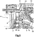
- the figure 2 shows a set 1 for a motor vehicle frame according to the present invention comprising a floor 2 extending substantially along the vehicle along a longitudinal axis X.
- This substantially flat floor 2 has an inner face and an outer face.
- the term "external face” means a face intended to be oriented towards the ground in rolling condition of the vehicle and “inner face” a face intended to be oriented on the opposite side to the ground in rolling condition of the vehicle, that is to say on the side of the passenger compartment of the vehicle.
- the assembly 1 also comprises an exhaust line 3 for gases resulting from combustion carried out in a heat engine located in the engine compartment. 4.
- the exhaust line 3 is located on the side of the outer face of the floor 2.
- This exhaust line 3 comprises in particular an exhaust duct 31 and a catalyst 32 belonging to a selective catalytic reduction system SCR (acronym for "Selective Catalytic Reduction” in English) for chemically reducing the nitrogen oxides present in the exhaust gas.
- Line 3 also has a silencer 33 in the rear part.
- the assembly 1 comprises a heat shield 5 positioned between the exhaust line 3 and the floor 2. Due to the underbody elements to avoid, such as piping networks, the fuel tank 14, and the reducing agent tank 13, the heat shield 5 has an elongation direction slightly crosswise with respect to the longitudinal axis X.
- the heat shield 5 defines a tunnel in which the exhaust line 3 is positioned. the occurrence, the screen 5 has an elongated U-shaped open towards the ground (when the vehicle is in rolling condition). Two protruding flanges 15, 16 extending along the side walls of the U allow the attachment of the screen 5 with the floor 2 (cf. figure 4 ).
- the heat shield 5 comprises, on the side of the engine compartment 4, a portion 50 rising towards the engine compartment 4 so as to guide the hot air from the engine compartment 4 inside the tunnel formed by the heat shield 5.
- the portion 50 at least partially closes the open zone Z located between the floor 2 and the heat shield 5 so as to create a funnel effect to guide the hot air in the tunnel.
- Such a configuration can convey the hot air from the engine compartment 4 to the rear of the vehicle by avoiding overheating of the sub-body elements.
- the heat shield 5 comprises two stamped portions 51 which each allow the passage of pipes under the screen 5.
- the embossing is performed in such a way that the hollow of each pressed portion 51 is positioned on the side of the floor 2 and that the convex portion 51 is directed towards the ground.
- the stamped portions 51 are curved so as to guide the hot air inside the tunnel towards the rear of the vehicle.
- the curved portions 51 have large radii of curvature so as to avoid creating turbulence likely to cause a deviation of the air flow to the sub-body elements.
- the embossed portion 51 located in the upper part of the screen 5 on the figure 5 may for example be provided to allow the passage of a duct 11 of heater; while the stamped portion 51 located in the lower part of the screen 5 on the figure 5 may for example be provided to allow the passage of brake lines 12 behind the heat shield 5.
- the heat shield 5 also has a curved portion 52 formed in a side wall of the U.
- This curved portion 52 extends between the exhaust line 3 and the reducing agent tank 13 for the SCR system.
- the curved portion 52 has a change in radius of curvature so as to have an overall elongated S shape. Such a shape makes it possible to maintain the side wall of the screen 5 away from the reducing agent reservoir 13, while avoiding the deflection of the hot air towards said reservoir 13.
- each side wall of the heat shield 5 is formed in each side wall of the heat shield 5. These release portions 53 allow the passage of a fastener to secure the heat shield 5 with the floor 2.
- Each portion clearance 53 is such that the distance separating the two side walls of the screen 5 increases gradually to a maximum of local spacing and then gradually decrease to a minimum of local spacing.
- the fasteners consist for example of nuts associated with large surface collars to maximize the bearing surface on the heat shield 5. This avoids damaging the heat shield 5 which is usually made of embossed aluminum.
- the heat shield 5 is preferably made in one piece. However, alternatively, it may be made in several parts, so that the closing portion 50 may be an insert which is fixed on the body of the screen 5.
- a part 6 is pressed against the inner periphery of the screen 5 and extends transversely with respect to a direction of longitudinal elongation of the screen 5.
- the part 6 has a U-shape complementary to the screen 5.
- This piece 6 is intended to ensure the maintenance of the heat shield 5 to the floor 2.
- the part 6 is provided with fixing means which hold in place pipes, such as fuel lines 61 and 61 return From the point of view of the engine compartment 4, the fuel lines 61, 62 pass behind the sealing portion 50 of the heat shield 5 and are pressed against the structure of the vehicle so that the heat shield 5 covers all.
- the assembly 1 comprises in addition to the heat shield 5, a heat shield 8, said rear screen, and a heat shield 9, said apron screen.
- the screen thermal rear 8 is located in the extension of the screen 5 and is intended to receive the silencer 33 of the exhaust line 3.
- the rear screen 8 extends substantially along the vehicle along the longitudinal axis X.
- the apron screen 9 is mounted between an apron 10 and the heat shield 5 of the vehicle. It is recalled that the deck 10 from the floor 2 is a wall which provides a separation between the interior of the passenger compartment and the engine compartment 4 of the vehicle.
- the apron screen 9 has a convex portion 90 oriented so as to break a wave generated during a crossing ford.
- the convex portion 90 is directed towards the ground and is oriented substantially perpendicular to a direction of advance of the wave. This protects the screen 5 from possible tearing by the wave.
- This aerodynamic shape also makes it possible not to disturb the conveying of the hot air underbody.
- the apron screen 9 and the screen 5 are superimposed relative to each other in a junction zone.
- the junction zone between the deck screen 9 and the screen 5 is preferably non-linear by having a curved shape having at least one change in radius of curvature.
Landscapes
- Physics & Mathematics (AREA)
- Acoustics & Sound (AREA)
- Engineering & Computer Science (AREA)
- Mechanical Engineering (AREA)
- Cooling, Air Intake And Gas Exhaust, And Fuel Tank Arrangements In Propulsion Units (AREA)
- Body Structure For Vehicles (AREA)
- Exhaust Silencers (AREA)
Description
- La présente invention porte sur un ensemble pour châssis de véhicule automobile. L'invention trouve une application particulièrement avantageuse, mais non exclusive, avec les véhicules automobiles de type utilitaire.
-
JP 2014 080059 A - De façon connue en soi, un ensemble pour châssis de véhicule automobile comporte un plancher s'étendant sensiblement le long du véhicule suivant un axe longitudinal. Dans certaines architectures de véhicule, en particulier les véhicules utilitaires, un écran thermique est positionné entre le plancher et une ligne d'échappement. Cet écran de protection thermique permet de protéger des éléments implantés en sous-caisse d'une surchauffe.
- Toutefois, comme cela est visible en
figure 1 , il existe une zone ouverte Z entre le plancher 2 et l'écran thermique 5 constituant un couloir dans lequel l'air chauffé par le groupe motopropulseur est susceptible de s'engouffrer, ce qui provoque la surchauffe des éléments sous le plancher; tels que des canalisations de frein, des canalisations de carburant 61, 62, un circuit de climatisation additionnel, un réservoir d'agent réducteur pour système de réduction catalytique sélective (ou SCR pour "Selective Catalytic Reduction" en anglais), ou un réservoir de carburant. En outre, la forme classique de l'écran thermique 5 à angles saillants présente l'inconvénient de dévier le flux d'air chaud issu du compartiment moteur vers les éléments précités, ce qui est également susceptible d'engendrer des anomalies de fonctionnement. - L'invention vise à remédier efficacement à au moins un de ces inconvénients en proposant un ensemble pour châssis de véhicule selon la revendication 1.
- L'invention permet ainsi d'éviter la surchauffe des éléments situés dans le couloir formé par la zone ouverte et d'éviter également la détérioration de leur fonctionnement. L'invention permet en outre de s'affranchir de protections spécifiques, telles que des patchs ou gaines thermiques destinées à chaque élément sensible à la chaleur, tel qu'un réservoir de carburant ou un réservoir d'agent réducteur.
- Selon une réalisation, des canalisations s'étendent longitudinalement entre ledit écran thermique et ledit plancher.
- Selon une réalisation, ledit écran thermique comporte au moins une portion emboutie pour autoriser le passage de canalisations sous ledit écran thermique.
- Selon une réalisation, ladite portion emboutie est bombée de manière à guider l'air chaud à l'intérieur dudit tunnel vers l'arrière dudit véhicule.
- Selon une réalisation, ledit écran thermique comporte une portion de forme courbe ayant un changement de rayon de courbure.
- Selon une réalisation, ladite portion de forme courbe est positionnée entre ladite ligne d'échappement et un réservoir tel qu'un réservoir d'agent réducteur pour système de réduction catalytique sélective. Ainsi, la portion de forme courbe présente une forme en S allongée permettant de convoyer l'air vers l'arrière tout en évitant à l'air chaud circulant dans le tunnel d'être dévié vers le réservoir d'agent réducteur.
- Selon une réalisation, ledit écran thermique comporte au moins une portion de dégagement, ladite portion de dégagement étant réalisée dans une paroi latérale dudit écran thermique de manière à autoriser le passage d'un organe de fixation pour fixer ledit écran thermique audit plancher. On évite ainsi de détériorer l'écran thermique qui est généralement réalisé en aluminium gaufré.
- Selon une réalisation, ledit ensemble comporte en outre une pièce de maintien de l'écran thermique munie de moyens de fixation pour maintenir en place des canalisations, telles que des canalisations de carburant.
- Selon une réalisation, ledit plancher est sensiblement plat.
- L'invention sera mieux comprise à la lecture de la description qui suit et à l'examen des figures qui l'accompagnent. Ces figures ne sont données qu'à titre illustratif mais nullement limitatif de l'invention.
- La
figure 1 , déjà décrite, est une vue en perspective de la zone ouverte située entre le plancher et l'écran thermique dans une configuration suivant l'état de la technique; - La
figure 2 est une vue de dessous d'un ensemble pour châssis selon la présente invention; - La
figure 3 est une vue en perspective détaillée de l'écran thermique selon la présente invention obturant au moins partiellement la zone ouverte; - La
figure 4 est une vue de dessous sur laquelle l'écran thermique selon l'invention représenté en transparence fait apparaître la pièce de maintien et les canalisations correspondantes s'étendant entre le plancher et l'écran thermique; - La
figure 5 est une vue de dessous sur laquelle l'écran thermique selon l'invention représenté en transparence fait apparaître le conduit d'aérotherme passant derrière une portion emboutie; - Les éléments identiques, similaires, ou analogues conservent la même référence d'une figure à l'autre.
- La
figure 2 montre un ensemble 1 pour châssis de véhicule automobile selon la présente invention comportant un plancher 2 s'étendant sensiblement le long du véhicule suivant un axe longitudinal X. Ce plancher 2 sensiblement plat présente une face interne et une face externe. Dans la description qui suit, on entend par "face externe" une face destinée à être orientée vers le sol en condition de roulage du véhicule et par "face interne" une face destinée à être orientée du côté opposé au sol en condition de roulage du véhicule, c'est-à-dire du côté de l'habitacle du véhicule. Et les termes relatifs comme "avant" ou "arrière" s'entendent respectivement par rapport au côté avant et au côté arrière du véhicule, un bord "avant" d'une pièce étant ainsi tourné vers l'avant du véhicule et un bord "arrière" étant tourné vers l'arrière du véhicule en condition de roulage en marche avant. - L'ensemble 1 comporte également une ligne d'échappement 3 pour des gaz issus d'une combustion réalisée dans un moteur thermique situé dans le compartiment moteur 4. La ligne d'échappement 3 est située du côté de la face externe du plancher 2. Cette ligne d'échappement 3 comprend notamment un conduit d'échappement 31 et un catalyseur 32 appartenant à un système de réduction sélective catalytique SCR (acronyme pour "Selective Catalytic Reduction" en anglais) permettant de réduire chimiquement les oxydes d'azote présents dans les gaz d'échappement. La ligne 3 comporte également un silencieux 33 en partie arrière.
- Par ailleurs, l'ensemble 1 comporte un écran thermique 5 positionné entre la ligne d'échappement 3 et le plancher 2. Du fait des éléments sous-caisse à éviter, tels que des réseaux de canalisations, le réservoir de carburant 14, et le réservoir d'agent réducteur 13, l'écran thermique 5 présente une direction d'allongement légèrement en travers par rapport à l'axe longitudinal X. L'écran thermique 5 définit un tunnel dans lequel est positionnée la ligne d'échappement 3. En l'occurrence, l'écran 5 présente une forme allongée en U ouvert vers le sol (lorsque le véhicule est en condition de roulage). Deux rebords 15, 16 saillants s'étendant le long des parois latérales du U permettent la fixation de l'écran 5 avec le plancher 2 (cf.
figure 4 ). - Plus précisément, comme cela est bien visible en
figure 3 , l'écran thermique 5 comporte, du côté du compartiment moteur 4, une portion 50 remontant en direction du compartiment moteur 4 de manière à guider l'air chaud issu du compartiment moteur 4 à l'intérieur du tunnel formé par l'écran thermique 5. Ainsi, la portion 50 obture au moins partiellement la zone ouverte Z située entre le plancher 2 et l'écran thermique 5 de manière à créer un effet d'entonnoir pour guider l'air chaud dans le tunnel. Une telle configuration permet de convoyer l'air chaud du compartiment moteur 4 vers l'arrière du véhicule en évitant la surchauffe des éléments sous-caisse. - En outre, l'écran thermique 5 comporte deux portions embouties 51 qui permettent chacune le passage de canalisations sous l'écran 5. L'emboutissement est réalisé de telle façon que le creux de chaque portion emboutie 51 est positionné du côté du plancher 2 et que la partie bombée 51 est dirigée vers le sol. Les portions embouties 51 sont bombées de manière à guider l'air chaud à l'intérieur du tunnel vers l'arrière du véhicule. Les portions bombées 51 présentent des grands rayons de courbure de manière à éviter de créer des turbulences susceptibles d'engendrer une déviation du flux d'air vers les éléments sous-caisse. La portion emboutie 51 située dans la partie haute de l'écran 5 sur la
figure 5 pourra par exemple être prévue pour autoriser le passage d'une canalisation 11 d'aérotherme; tandis que la portion emboutie 51 située dans la partie basse de l'écran 5 sur lafigure 5 pourra par exemple être prévue pour autoriser le passage de canalisations de freins 12 derrière l'écran thermique 5. - L'écran thermique 5 comporte également une portion de forme courbe 52 ménagée dans une paroi latérale du U. Cette portion de forme courbe 52 s'étend entre la ligne d'échappement 3 et le réservoir d'agent réducteur 13 pour le système SCR. La portion de forme courbe 52 présente un changement de rayon de courbure de manière à avoir globalement une forme en S allongée. Une telle forme permet de maintenir la paroi latérale de l'écran 5 à distance du réservoir d'agent réducteur 13, tout en évitant la déviation de l'air chaud vers ledit réservoir 13.
- Par ailleurs, deux portions de dégagement arrondies 53 sont réalisées dans chaque paroi latérale de l'écran thermique 5. Ces portions de dégagement 53 permettent le passage d'un organe de fixation pour solidariser l'écran thermique 5 avec le plancher 2. Chaque portion de dégagement 53 est telle que la distance séparant les deux parois latérales de l'écran 5 augmente progressivement jusqu'à un maximum d'écartement local pour ensuite diminuer progressivement jusqu'à un minimum d'écartement local. Les organes de fixation consistent par exemple en des écrous associés à des collerettes de grande surface afin de maximiser la surface d'appui sur l'écran thermique 5. On évite ainsi de détériorer l'écran thermique 5 qui est généralement réalisé en aluminium gaufré.
- L'écran thermique 5 est de préférence réalisé en une seule pièce. Toutefois, en variante, il pourra être réalisé en plusieurs pièces, de telle façon que la portion d'obturation 50 pourra être une pièce rapportée qui est fixée sur le corps de l'écran 5.
- Une pièce 6 est plaquée contre la périphérie interne de l'écran 5 et s'étend transversalement par rapport à une direction d'allongement longitudinale de l'écran 5. A cet effet, la pièce 6 présente une forme en U complémentaire de l'écran 5. Cette pièce 6 vise à assurer le maintien de l'écran thermique 5 au plancher 2. Avantageusement, la pièce 6 est munie de moyens de fixation qui maintiennent en place des canalisations, telles que des canalisations de carburant aller 61 et retour 62. Du point de vue du compartiment moteur 4, les canalisations de carburant 61, 62 passent derrière la portion d'obturation 50 de l'écran thermique 5 et sont plaquées contre la structure du véhicule de manière à ce que l'écran thermique 5 recouvre l'ensemble.
- Par ailleurs, l'ensemble 1 comporte en plus de l'écran thermique 5, un écran thermique 8, dit écran arrière, et un écran thermique 9, dit écran de tablier. L'écran thermique arrière 8 est situé dans le prolongement de l'écran 5 et est destiné à recevoir le silencieux 33 de la ligne d'échappement 3. L'écran arrière 8 s'étend sensiblement le long du véhicule suivant l'axe longitudinal X.
- L'écran de tablier 9 est monté entre un tablier 10 et l'écran thermique 5 du véhicule. On rappelle que le tablier 10 issu du plancher 2 est une paroi qui assure une séparation entre l'intérieur de l'habitacle et le compartiment moteur 4 du véhicule. L'écran de tablier 9 présente une portion bombée 90 orientée de manière à pouvoir casser une vague générée lors d'un passage au gué. La portion bombée 90 est dirigée vers le sol et est orientée sensiblement perpendiculairement à une direction d'avancement de la vague. Cela permet de protéger l'écran 5 d'un éventuel arrachement par la vague. Cette forme aérodynamique permet en outre de ne pas perturber le convoyage de l'air chaud sous-caisse.
- L'écran de tablier 9 et l'écran 5 se superposent l'un par rapport à l'autre dans une zone de jonction. La zone de jonction entre l'écran de tablier 9 et l'écran 5 est de préférence non linéaire en présentant une forme courbe ayant au moins un changement de rayon de courbure. Une telle configuration d'assemblage permet notamment de garantir un bon contact d'appui entre les deux écrans 5 et 9, ainsi que d'améliorer les prestations thermiques en supprimant l'espace entre les écrans 5 et 9, et les prestations phoniques en évitant que les écrans 5 et 9 vibrent en cours d'utilisation du véhicule.
Claims (14)
- Ensemble (1) pour châssis de véhicule comportant:- un plancher (2) destiné à s'étendre sensiblement le long du véhicule suivant un axe longitudinal (X),- une ligne d'échappement (3) pour des gaz issus d'une combustion dans un moteur thermique situé dans un compartiment moteur (4),- un écran thermique (5) définissant un tunnel dans lequel est positionnée ladite ligne d'échappement (3),- un tablier (10) issu du plancher, et- un écran de tablier (9) qui est monté entre l'écran thermique (5) et le tablier (10),ledit écran thermique (5) comportant, du côté du compartiment moteur (4), une portion (50) remontant en direction dudit compartiment moteur (4) de manière à guider un air chaud à l'intérieur dudit tunnel défini par l'écran thermique (5), caractérisé en ce que le tablier (10) comporte une portion bombée (90) orientée de manière à pouvoir casser une vague générée lors d'un passage au gué, ladite portion bombée (90) étant dirigée vers le sol et étant orientée sensiblement perpendiculairement à une direction d'avancement de ladite vague.
- Ensemble selon la revendication 1, caractérisé en ce que des canalisations (11, 12, 61, 62) s'étendent longitudinalement entre ledit écran thermique et ledit plancher.
- Ensemble selon la revendication 1 ou 2, caractérisé en ce que ledit écran thermique (5) comporte au moins une portion emboutie (51) pour autoriser le passage de canalisations (11, 12) sous ledit écran thermique (5).
- Ensemble selon la revendication 3, caractérisé en ce que ladite portion emboutie (51) est bombée de manière à guider l'air chaud à l'intérieur dudit tunnel vers l'arrière dudit véhicule.
- Ensemble selon l'une quelconque des revendications 1 à 4, caractérisé en ce que ledit écran thermique (5) comporte une portion de forme courbe (52) ayant un changement de rayon de courbure.
- Ensemble selon la revendication 5, caractérisé en ce que ladite portion de forme courbe (52) est positionnée entre ladite ligne d'échappement (3) et un réservoir tel qu'un réservoir d'agent réducteur pour système de réduction catalytique sélective (13).
- Ensemble selon l'une quelconque des revendications 1 à 6, caractérisé en ce que ledit écran thermique (5) comporte au moins une portion de dégagement (53), ladite portion de dégagement (53) étant réalisée dans une paroi latérale dudit écran thermique (5) de manière à autoriser le passage d'un organe de fixation pour fixer ledit écran thermique (5) audit plancher (2).
- Ensemble selon l'une quelconque des revendications 1 à 7, caractérisé en ce qu'il comporte en outre une pièce de maintien (6) de l'écran thermique (5) munie de moyens de fixation pour maintenir en place des canalisations, telles que des canalisations de carburant (61, 62).
- Ensemble selon l'une quelconque des revendications 1 à 8, caractérisé en ce que ledit plancher (2) est sensiblement plat.
- Ensemble selon l'une des revendications précédentes, caractérisé en ce que l'écran thermique (5) présente une forme allongée en U ouvert vers le sol et comprend de préférence deux rebords saillants (15,16) s'étendant le long des parois latérales du U pour fixer l'écran (5) au plancher (2).
- Ensemble selon l'une des revendications précédentes, caractérisé en ce que la portion (50) de l'écran thermique (5) obture au moins partiellement la zone (Z) située entre le plancher (2) et l'écran thermique (5).
- Ensemble selon l'une des revendications précédentes, caractérisé en ce que l'écran thermique (5) est réalisé en une seule pièce.
- Ensemble selon l'une des revendications précédentes, caractérisé en ce qu'il comprend aussi un écran thermique arrière (8) situé dans le prolongement de l'écran thermique (5) et notamment destiné à recevoir le silencieux (33) de la ligne d'échappement (3).
- Ensemble selon l'une des revendications précédentes, caractérisé en ce que l'écran de tablier (9) et l'écran thermique (5) se superposent l'un par rapport à l'autre dans une zone de jonction, ladite zone de jonction étant de préférence non linéaire et présentant une forme courbe ayant au moins un changement de rayon de courbure.
Applications Claiming Priority (2)
| Application Number | Priority Date | Filing Date | Title |
|---|---|---|---|
| FR1559427A FR3041913B1 (fr) | 2015-10-05 | 2015-10-05 | Ensemble pour chassis de vehicule automobile |
| PCT/FR2016/052346 WO2017060580A1 (fr) | 2015-10-05 | 2016-09-16 | Ensemble pour châssis de vehicule automobile |
Publications (2)
| Publication Number | Publication Date |
|---|---|
| EP3359423A1 EP3359423A1 (fr) | 2018-08-15 |
| EP3359423B1 true EP3359423B1 (fr) | 2019-10-30 |
Family
ID=55072889
Family Applications (1)
| Application Number | Title | Priority Date | Filing Date |
|---|---|---|---|
| EP16785195.5A Active EP3359423B1 (fr) | 2015-10-05 | 2016-09-16 | Ensemble pour châssis de vehicule automobile |
Country Status (4)
| Country | Link |
|---|---|
| EP (1) | EP3359423B1 (fr) |
| CN (1) | CN108136974B (fr) |
| FR (1) | FR3041913B1 (fr) |
| WO (1) | WO2017060580A1 (fr) |
Families Citing this family (1)
| Publication number | Priority date | Publication date | Assignee | Title |
|---|---|---|---|---|
| JP2020104794A (ja) * | 2018-12-28 | 2020-07-09 | いすゞ自動車株式会社 | 流量調整部の遮熱構造 |
Family Cites Families (11)
| Publication number | Priority date | Publication date | Assignee | Title |
|---|---|---|---|---|
| JPS5262815A (en) * | 1975-11-17 | 1977-05-24 | Mitsubishi Motors Corp | Method of manufacturing sound insulation double wall |
| JP3439432B2 (ja) * | 2000-06-27 | 2003-08-25 | 本田技研工業株式会社 | 車両の前部構造 |
| JP3531816B2 (ja) * | 2001-06-06 | 2004-05-31 | 本田技研工業株式会社 | 車両フロアの遮熱装置 |
| JP2006036089A (ja) * | 2004-07-28 | 2006-02-09 | Kasai Kogyo Co Ltd | 車両用成形天井及びその製造方法 |
| DE202004015698U1 (de) * | 2004-10-11 | 2004-12-16 | Rieter Technologies Ag | Hitzeschild |
| CN201941695U (zh) * | 2010-12-02 | 2011-08-24 | 重庆长安汽车股份有限公司 | 一种汽车用隔热板安装支架 |
| FR2975130A1 (fr) * | 2011-05-12 | 2012-11-16 | Cera | Ecran de protection thermique et acoustique pour une ligne d’echappement de vehicule automobile |
| JP2014080059A (ja) * | 2012-10-15 | 2014-05-08 | Toyota Motor Corp | フロアヒートインシュレータ |
| FR2999230B1 (fr) * | 2012-12-06 | 2014-12-26 | Peugeot Citroen Automobiles Sa | Filtre a particules |
| CN203198877U (zh) * | 2013-03-06 | 2013-09-18 | 三河世原汽车科技有限公司 | 汽车用隔热板 |
| CN103206292A (zh) * | 2013-04-01 | 2013-07-17 | 重庆长安汽车股份有限公司 | 一种汽车发动机排气系统隔热罩的安装构件 |
-
2015
- 2015-10-05 FR FR1559427A patent/FR3041913B1/fr not_active Expired - Fee Related
-
2016
- 2016-09-16 WO PCT/FR2016/052346 patent/WO2017060580A1/fr unknown
- 2016-09-16 EP EP16785195.5A patent/EP3359423B1/fr active Active
- 2016-09-16 CN CN201680058582.6A patent/CN108136974B/zh active Active
Non-Patent Citations (1)
| Title |
|---|
| None * |
Also Published As
| Publication number | Publication date |
|---|---|
| CN108136974B (zh) | 2021-06-22 |
| EP3359423A1 (fr) | 2018-08-15 |
| WO2017060580A1 (fr) | 2017-04-13 |
| FR3041913A1 (fr) | 2017-04-07 |
| CN108136974A (zh) | 2018-06-08 |
| FR3041913B1 (fr) | 2019-01-25 |
Similar Documents
| Publication | Publication Date | Title |
|---|---|---|
| EP2914825B1 (fr) | Ensemble pour châssis de vehicule automobile facilitant l'implantation d'une sonde | |
| EP3591178B1 (fr) | Module d'étanchéité de turbomachine | |
| WO2013024218A1 (fr) | Cône d'éjection pour turboréacteur d'aéronef | |
| WO2007026063A1 (fr) | Traverse aeraulique pour vehicule automobile | |
| EP3359423B1 (fr) | Ensemble pour châssis de vehicule automobile | |
| EP2344384B1 (fr) | Nacelle pour turboreacteur | |
| EP3775650B1 (fr) | Dispositif de maintien securise et de protection thermique d'elements | |
| FR2964077A1 (fr) | Ensemble pour chassis d'un vehicule notamment de type electrique | |
| EP2923872A1 (fr) | Ensemble pour châssis de véhicule automobile à double écrans de protection thermique | |
| FR2933045A1 (fr) | Dispositif d'admission d'air pour vehicule automobibile | |
| EP3113982B1 (fr) | Ensemble pour châssis de véhicule automobile | |
| EP2173604B1 (fr) | Agencement de fixation de deux elements de carrosserie adjacents | |
| FR3036664A1 (fr) | Ensemble sous-plancher arriere d’un vehicule automobile comprenant un dispositif de recyclage des vapeurs de carburant | |
| FR2968068A1 (fr) | Dispositif de distribution d'air a ailettes de guidage d'air a deformations complementaires pour assurer l'etancheite | |
| WO2016038265A1 (fr) | Véhicule automobile a ligne d'échappement courte et écran de protection thermique du réservoir de carburant de ce véhicule | |
| EP3393890B1 (fr) | Passage de roue de vehicule automobile equipe d'un element aerodynamique | |
| WO2016038266A1 (fr) | Vehicule automobile a ligne d'echappement courte et ecran de protection thermique du reservoir de carburant de ce vehicule | |
| EP2978658B1 (fr) | Ensemble pour châssis comportant un réservoir de stockage d'un agent de dépollution et véhicule automobile correspondant | |
| FR3088373A1 (fr) | Joint d’etancheite pour nacelle de turboreacteur d’aeronef | |
| FR3023821A1 (fr) | Agencement sous-plancher de vehicule automobile | |
| FR3130316A1 (fr) | Conduit d’échappement comportant un moyen de maintien d’un écran | |
| FR3069888A1 (fr) | Silencieux pour ligne d'echappement de moteur thermique | |
| FR2912080A3 (fr) | Vehicule automobile a adherence amelioree sur chaussee humide | |
| FR2951410A1 (fr) | Agencement d'un groupe moto ventilateur et d'un radiateur | |
| WO2015150657A1 (fr) | Vehicule automobile comportant un conduit de sortie d'air de turbocompresseur en partie souple |
Legal Events
| Date | Code | Title | Description |
|---|---|---|---|
| STAA | Information on the status of an ep patent application or granted ep patent |
Free format text: STATUS: UNKNOWN |
|
| STAA | Information on the status of an ep patent application or granted ep patent |
Free format text: STATUS: THE INTERNATIONAL PUBLICATION HAS BEEN MADE |
|
| PUAI | Public reference made under article 153(3) epc to a published international application that has entered the european phase |
Free format text: ORIGINAL CODE: 0009012 |
|
| STAA | Information on the status of an ep patent application or granted ep patent |
Free format text: STATUS: REQUEST FOR EXAMINATION WAS MADE |
|
| 17P | Request for examination filed |
Effective date: 20180308 |
|
| AK | Designated contracting states |
Kind code of ref document: A1 Designated state(s): AL AT BE BG CH CY CZ DE DK EE ES FI FR GB GR HR HU IE IS IT LI LT LU LV MC MK MT NL NO PL PT RO RS SE SI SK SM TR |
|
| AX | Request for extension of the european patent |
Extension state: BA ME |
|
| DAV | Request for validation of the european patent (deleted) | ||
| DAX | Request for extension of the european patent (deleted) | ||
| GRAP | Despatch of communication of intention to grant a patent |
Free format text: ORIGINAL CODE: EPIDOSNIGR1 |
|
| STAA | Information on the status of an ep patent application or granted ep patent |
Free format text: STATUS: GRANT OF PATENT IS INTENDED |
|
| INTG | Intention to grant announced |
Effective date: 20190418 |
|
| GRAS | Grant fee paid |
Free format text: ORIGINAL CODE: EPIDOSNIGR3 |
|
| GRAA | (expected) grant |
Free format text: ORIGINAL CODE: 0009210 |
|
| STAA | Information on the status of an ep patent application or granted ep patent |
Free format text: STATUS: THE PATENT HAS BEEN GRANTED |
|
| AK | Designated contracting states |
Kind code of ref document: B1 Designated state(s): AL AT BE BG CH CY CZ DE DK EE ES FI FR GB GR HR HU IE IS IT LI LT LU LV MC MK MT NL NO PL PT RO RS SE SI SK SM TR |
|
| REG | Reference to a national code |
Ref country code: GB Ref legal event code: FG4D Free format text: NOT ENGLISH |
|
| REG | Reference to a national code |
Ref country code: CH Ref legal event code: EP |
|
| REG | Reference to a national code |
Ref country code: AT Ref legal event code: REF Ref document number: 1195782 Country of ref document: AT Kind code of ref document: T Effective date: 20191115 |
|
| REG | Reference to a national code |
Ref country code: DE Ref legal event code: R096 Ref document number: 602016023431 Country of ref document: DE |
|
| REG | Reference to a national code |
Ref country code: IE Ref legal event code: FG4D Free format text: LANGUAGE OF EP DOCUMENT: FRENCH |
|
| REG | Reference to a national code |
Ref country code: DE Ref legal event code: R084 Ref document number: 602016023431 Country of ref document: DE |
|
| REG | Reference to a national code |
Ref country code: GB Ref legal event code: 746 Effective date: 20200130 |
|
| REG | Reference to a national code |
Ref country code: LT Ref legal event code: MG4D |
|
| PG25 | Lapsed in a contracting state [announced via postgrant information from national office to epo] |
Ref country code: PL Free format text: LAPSE BECAUSE OF FAILURE TO SUBMIT A TRANSLATION OF THE DESCRIPTION OR TO PAY THE FEE WITHIN THE PRESCRIBED TIME-LIMIT Effective date: 20191030 Ref country code: LT Free format text: LAPSE BECAUSE OF FAILURE TO SUBMIT A TRANSLATION OF THE DESCRIPTION OR TO PAY THE FEE WITHIN THE PRESCRIBED TIME-LIMIT Effective date: 20191030 Ref country code: GR Free format text: LAPSE BECAUSE OF FAILURE TO SUBMIT A TRANSLATION OF THE DESCRIPTION OR TO PAY THE FEE WITHIN THE PRESCRIBED TIME-LIMIT Effective date: 20200131 Ref country code: NO Free format text: LAPSE BECAUSE OF FAILURE TO SUBMIT A TRANSLATION OF THE DESCRIPTION OR TO PAY THE FEE WITHIN THE PRESCRIBED TIME-LIMIT Effective date: 20200130 Ref country code: NL Free format text: LAPSE BECAUSE OF FAILURE TO SUBMIT A TRANSLATION OF THE DESCRIPTION OR TO PAY THE FEE WITHIN THE PRESCRIBED TIME-LIMIT Effective date: 20191030 Ref country code: PT Free format text: LAPSE BECAUSE OF FAILURE TO SUBMIT A TRANSLATION OF THE DESCRIPTION OR TO PAY THE FEE WITHIN THE PRESCRIBED TIME-LIMIT Effective date: 20200302 Ref country code: FI Free format text: LAPSE BECAUSE OF FAILURE TO SUBMIT A TRANSLATION OF THE DESCRIPTION OR TO PAY THE FEE WITHIN THE PRESCRIBED TIME-LIMIT Effective date: 20191030 Ref country code: BG Free format text: LAPSE BECAUSE OF FAILURE TO SUBMIT A TRANSLATION OF THE DESCRIPTION OR TO PAY THE FEE WITHIN THE PRESCRIBED TIME-LIMIT Effective date: 20200130 Ref country code: SE Free format text: LAPSE BECAUSE OF FAILURE TO SUBMIT A TRANSLATION OF THE DESCRIPTION OR TO PAY THE FEE WITHIN THE PRESCRIBED TIME-LIMIT Effective date: 20191030 Ref country code: LV Free format text: LAPSE BECAUSE OF FAILURE TO SUBMIT A TRANSLATION OF THE DESCRIPTION OR TO PAY THE FEE WITHIN THE PRESCRIBED TIME-LIMIT Effective date: 20191030 |
|
| REG | Reference to a national code |
Ref country code: NL Ref legal event code: MP Effective date: 20191030 |
|
| PG25 | Lapsed in a contracting state [announced via postgrant information from national office to epo] |
Ref country code: HR Free format text: LAPSE BECAUSE OF FAILURE TO SUBMIT A TRANSLATION OF THE DESCRIPTION OR TO PAY THE FEE WITHIN THE PRESCRIBED TIME-LIMIT Effective date: 20191030 Ref country code: IS Free format text: LAPSE BECAUSE OF FAILURE TO SUBMIT A TRANSLATION OF THE DESCRIPTION OR TO PAY THE FEE WITHIN THE PRESCRIBED TIME-LIMIT Effective date: 20200229 Ref country code: RS Free format text: LAPSE BECAUSE OF FAILURE TO SUBMIT A TRANSLATION OF THE DESCRIPTION OR TO PAY THE FEE WITHIN THE PRESCRIBED TIME-LIMIT Effective date: 20191030 |
|
| PG25 | Lapsed in a contracting state [announced via postgrant information from national office to epo] |
Ref country code: AL Free format text: LAPSE BECAUSE OF FAILURE TO SUBMIT A TRANSLATION OF THE DESCRIPTION OR TO PAY THE FEE WITHIN THE PRESCRIBED TIME-LIMIT Effective date: 20191030 |
|
| PG25 | Lapsed in a contracting state [announced via postgrant information from national office to epo] |
Ref country code: CZ Free format text: LAPSE BECAUSE OF FAILURE TO SUBMIT A TRANSLATION OF THE DESCRIPTION OR TO PAY THE FEE WITHIN THE PRESCRIBED TIME-LIMIT Effective date: 20191030 Ref country code: ES Free format text: LAPSE BECAUSE OF FAILURE TO SUBMIT A TRANSLATION OF THE DESCRIPTION OR TO PAY THE FEE WITHIN THE PRESCRIBED TIME-LIMIT Effective date: 20191030 Ref country code: EE Free format text: LAPSE BECAUSE OF FAILURE TO SUBMIT A TRANSLATION OF THE DESCRIPTION OR TO PAY THE FEE WITHIN THE PRESCRIBED TIME-LIMIT Effective date: 20191030 Ref country code: DK Free format text: LAPSE BECAUSE OF FAILURE TO SUBMIT A TRANSLATION OF THE DESCRIPTION OR TO PAY THE FEE WITHIN THE PRESCRIBED TIME-LIMIT Effective date: 20191030 Ref country code: RO Free format text: LAPSE BECAUSE OF FAILURE TO SUBMIT A TRANSLATION OF THE DESCRIPTION OR TO PAY THE FEE WITHIN THE PRESCRIBED TIME-LIMIT Effective date: 20191030 |
|
| REG | Reference to a national code |
Ref country code: DE Ref legal event code: R097 Ref document number: 602016023431 Country of ref document: DE |
|
| REG | Reference to a national code |
Ref country code: AT Ref legal event code: MK05 Ref document number: 1195782 Country of ref document: AT Kind code of ref document: T Effective date: 20191030 |
|
| PG25 | Lapsed in a contracting state [announced via postgrant information from national office to epo] |
Ref country code: IT Free format text: LAPSE BECAUSE OF FAILURE TO SUBMIT A TRANSLATION OF THE DESCRIPTION OR TO PAY THE FEE WITHIN THE PRESCRIBED TIME-LIMIT Effective date: 20191030 Ref country code: SK Free format text: LAPSE BECAUSE OF FAILURE TO SUBMIT A TRANSLATION OF THE DESCRIPTION OR TO PAY THE FEE WITHIN THE PRESCRIBED TIME-LIMIT Effective date: 20191030 Ref country code: SM Free format text: LAPSE BECAUSE OF FAILURE TO SUBMIT A TRANSLATION OF THE DESCRIPTION OR TO PAY THE FEE WITHIN THE PRESCRIBED TIME-LIMIT Effective date: 20191030 |
|
| PLBE | No opposition filed within time limit |
Free format text: ORIGINAL CODE: 0009261 |
|
| STAA | Information on the status of an ep patent application or granted ep patent |
Free format text: STATUS: NO OPPOSITION FILED WITHIN TIME LIMIT |
|
| 26N | No opposition filed |
Effective date: 20200731 |
|
| PG25 | Lapsed in a contracting state [announced via postgrant information from national office to epo] |
Ref country code: AT Free format text: LAPSE BECAUSE OF FAILURE TO SUBMIT A TRANSLATION OF THE DESCRIPTION OR TO PAY THE FEE WITHIN THE PRESCRIBED TIME-LIMIT Effective date: 20191030 Ref country code: SI Free format text: LAPSE BECAUSE OF FAILURE TO SUBMIT A TRANSLATION OF THE DESCRIPTION OR TO PAY THE FEE WITHIN THE PRESCRIBED TIME-LIMIT Effective date: 20191030 |
|
| REG | Reference to a national code |
Ref country code: CH Ref legal event code: PL |
|
| REG | Reference to a national code |
Ref country code: BE Ref legal event code: MM Effective date: 20200930 |
|
| PG25 | Lapsed in a contracting state [announced via postgrant information from national office to epo] |
Ref country code: LU Free format text: LAPSE BECAUSE OF NON-PAYMENT OF DUE FEES Effective date: 20200916 |
|
| PG25 | Lapsed in a contracting state [announced via postgrant information from national office to epo] |
Ref country code: IE Free format text: LAPSE BECAUSE OF NON-PAYMENT OF DUE FEES Effective date: 20200916 Ref country code: LI Free format text: LAPSE BECAUSE OF NON-PAYMENT OF DUE FEES Effective date: 20200930 Ref country code: CH Free format text: LAPSE BECAUSE OF NON-PAYMENT OF DUE FEES Effective date: 20200930 Ref country code: BE Free format text: LAPSE BECAUSE OF NON-PAYMENT OF DUE FEES Effective date: 20200930 |
|
| PG25 | Lapsed in a contracting state [announced via postgrant information from national office to epo] |
Ref country code: TR Free format text: LAPSE BECAUSE OF FAILURE TO SUBMIT A TRANSLATION OF THE DESCRIPTION OR TO PAY THE FEE WITHIN THE PRESCRIBED TIME-LIMIT Effective date: 20191030 Ref country code: MT Free format text: LAPSE BECAUSE OF FAILURE TO SUBMIT A TRANSLATION OF THE DESCRIPTION OR TO PAY THE FEE WITHIN THE PRESCRIBED TIME-LIMIT Effective date: 20191030 Ref country code: CY Free format text: LAPSE BECAUSE OF FAILURE TO SUBMIT A TRANSLATION OF THE DESCRIPTION OR TO PAY THE FEE WITHIN THE PRESCRIBED TIME-LIMIT Effective date: 20191030 |
|
| PG25 | Lapsed in a contracting state [announced via postgrant information from national office to epo] |
Ref country code: MK Free format text: LAPSE BECAUSE OF FAILURE TO SUBMIT A TRANSLATION OF THE DESCRIPTION OR TO PAY THE FEE WITHIN THE PRESCRIBED TIME-LIMIT Effective date: 20191030 Ref country code: MC Free format text: LAPSE BECAUSE OF FAILURE TO SUBMIT A TRANSLATION OF THE DESCRIPTION OR TO PAY THE FEE WITHIN THE PRESCRIBED TIME-LIMIT Effective date: 20191030 |
|
| PGFP | Annual fee paid to national office [announced via postgrant information from national office to epo] |
Ref country code: GB Payment date: 20230823 Year of fee payment: 8 |
|
| PGFP | Annual fee paid to national office [announced via postgrant information from national office to epo] |
Ref country code: FR Payment date: 20230822 Year of fee payment: 8 Ref country code: DE Payment date: 20230822 Year of fee payment: 8 |
|
| REG | Reference to a national code |
Ref country code: DE Ref legal event code: R081 Ref document number: 602016023431 Country of ref document: DE Owner name: STELLANTIS AUTO SAS, FR Free format text: FORMER OWNER: PSA AUTOMOBILES S.A., POISSY, FR |