EP3357473A2 - Am körper tragbare fingerrehabilitationsvorrichtung - Google Patents
Am körper tragbare fingerrehabilitationsvorrichtung Download PDFInfo
- Publication number
- EP3357473A2 EP3357473A2 EP17210786.4A EP17210786A EP3357473A2 EP 3357473 A2 EP3357473 A2 EP 3357473A2 EP 17210786 A EP17210786 A EP 17210786A EP 3357473 A2 EP3357473 A2 EP 3357473A2
- Authority
- EP
- European Patent Office
- Prior art keywords
- pivot hole
- finger
- thumb
- coupled
- motor
- Prior art date
- Legal status (The legal status is an assumption and is not a legal conclusion. Google has not performed a legal analysis and makes no representation as to the accuracy of the status listed.)
- Granted
Links
Images






Classifications
-
- A—HUMAN NECESSITIES
- A61—MEDICAL OR VETERINARY SCIENCE; HYGIENE
- A61H—PHYSICAL THERAPY APPARATUS, e.g. DEVICES FOR LOCATING OR STIMULATING REFLEX POINTS IN THE BODY; ARTIFICIAL RESPIRATION; MASSAGE; BATHING DEVICES FOR SPECIAL THERAPEUTIC OR HYGIENIC PURPOSES OR SPECIFIC PARTS OF THE BODY
- A61H1/00—Apparatus for passive exercising; Vibrating apparatus; Chiropractic devices, e.g. body impacting devices, external devices for briefly extending or aligning unbroken bones
- A61H1/02—Stretching or bending or torsioning apparatus for exercising
- A61H1/0274—Stretching or bending or torsioning apparatus for exercising for the upper limbs
- A61H1/0285—Hand
- A61H1/0288—Fingers
-
- B—PERFORMING OPERATIONS; TRANSPORTING
- B25—HAND TOOLS; PORTABLE POWER-DRIVEN TOOLS; MANIPULATORS
- B25J—MANIPULATORS; CHAMBERS PROVIDED WITH MANIPULATION DEVICES
- B25J9/00—Program-controlled manipulators
- B25J9/10—Program-controlled manipulators characterised by positioning means for manipulator elements
- B25J9/12—Program-controlled manipulators characterised by positioning means for manipulator elements electric
- B25J9/123—Linear actuators
-
- A—HUMAN NECESSITIES
- A61—MEDICAL OR VETERINARY SCIENCE; HYGIENE
- A61H—PHYSICAL THERAPY APPARATUS, e.g. DEVICES FOR LOCATING OR STIMULATING REFLEX POINTS IN THE BODY; ARTIFICIAL RESPIRATION; MASSAGE; BATHING DEVICES FOR SPECIAL THERAPEUTIC OR HYGIENIC PURPOSES OR SPECIFIC PARTS OF THE BODY
- A61H2201/00—Characteristics of apparatus not provided for in the preceding codes
- A61H2201/01—Constructive details
- A61H2201/0157—Constructive details portable
-
- A—HUMAN NECESSITIES
- A61—MEDICAL OR VETERINARY SCIENCE; HYGIENE
- A61H—PHYSICAL THERAPY APPARATUS, e.g. DEVICES FOR LOCATING OR STIMULATING REFLEX POINTS IN THE BODY; ARTIFICIAL RESPIRATION; MASSAGE; BATHING DEVICES FOR SPECIAL THERAPEUTIC OR HYGIENIC PURPOSES OR SPECIFIC PARTS OF THE BODY
- A61H2201/00—Characteristics of apparatus not provided for in the preceding codes
- A61H2201/12—Driving means
- A61H2201/1207—Driving means with electric or magnetic drive
- A61H2201/123—Linear drive
-
- A—HUMAN NECESSITIES
- A61—MEDICAL OR VETERINARY SCIENCE; HYGIENE
- A61H—PHYSICAL THERAPY APPARATUS, e.g. DEVICES FOR LOCATING OR STIMULATING REFLEX POINTS IN THE BODY; ARTIFICIAL RESPIRATION; MASSAGE; BATHING DEVICES FOR SPECIAL THERAPEUTIC OR HYGIENIC PURPOSES OR SPECIFIC PARTS OF THE BODY
- A61H2201/00—Characteristics of apparatus not provided for in the preceding codes
- A61H2201/16—Physical interface with patient
- A61H2201/1602—Physical interface with patient kind of interface, e.g. head rest, knee support or lumbar support
- A61H2201/1635—Hand or arm, e.g. handle
- A61H2201/1638—Holding means therefor
-
- A—HUMAN NECESSITIES
- A61—MEDICAL OR VETERINARY SCIENCE; HYGIENE
- A61H—PHYSICAL THERAPY APPARATUS, e.g. DEVICES FOR LOCATING OR STIMULATING REFLEX POINTS IN THE BODY; ARTIFICIAL RESPIRATION; MASSAGE; BATHING DEVICES FOR SPECIAL THERAPEUTIC OR HYGIENIC PURPOSES OR SPECIFIC PARTS OF THE BODY
- A61H2201/00—Characteristics of apparatus not provided for in the preceding codes
- A61H2201/16—Physical interface with patient
- A61H2201/1602—Physical interface with patient kind of interface, e.g. head rest, knee support or lumbar support
- A61H2201/165—Wearable interfaces
-
- A—HUMAN NECESSITIES
- A61—MEDICAL OR VETERINARY SCIENCE; HYGIENE
- A61H—PHYSICAL THERAPY APPARATUS, e.g. DEVICES FOR LOCATING OR STIMULATING REFLEX POINTS IN THE BODY; ARTIFICIAL RESPIRATION; MASSAGE; BATHING DEVICES FOR SPECIAL THERAPEUTIC OR HYGIENIC PURPOSES OR SPECIFIC PARTS OF THE BODY
- A61H2201/00—Characteristics of apparatus not provided for in the preceding codes
- A61H2201/16—Physical interface with patient
- A61H2201/1657—Movement of interface, i.e. force application means
- A61H2201/1664—Movement of interface, i.e. force application means linear
-
- A—HUMAN NECESSITIES
- A61—MEDICAL OR VETERINARY SCIENCE; HYGIENE
- A61H—PHYSICAL THERAPY APPARATUS, e.g. DEVICES FOR LOCATING OR STIMULATING REFLEX POINTS IN THE BODY; ARTIFICIAL RESPIRATION; MASSAGE; BATHING DEVICES FOR SPECIAL THERAPEUTIC OR HYGIENIC PURPOSES OR SPECIFIC PARTS OF THE BODY
- A61H2201/00—Characteristics of apparatus not provided for in the preceding codes
- A61H2201/16—Physical interface with patient
- A61H2201/1657—Movement of interface, i.e. force application means
- A61H2201/1676—Pivoting
-
- A—HUMAN NECESSITIES
- A61—MEDICAL OR VETERINARY SCIENCE; HYGIENE
- A61H—PHYSICAL THERAPY APPARATUS, e.g. DEVICES FOR LOCATING OR STIMULATING REFLEX POINTS IN THE BODY; ARTIFICIAL RESPIRATION; MASSAGE; BATHING DEVICES FOR SPECIAL THERAPEUTIC OR HYGIENIC PURPOSES OR SPECIFIC PARTS OF THE BODY
- A61H2201/00—Characteristics of apparatus not provided for in the preceding codes
- A61H2201/50—Control means thereof
- A61H2201/5007—Control means thereof computer controlled
- A61H2201/501—Control means thereof computer controlled connected to external computer devices or networks
-
- A—HUMAN NECESSITIES
- A61—MEDICAL OR VETERINARY SCIENCE; HYGIENE
- A61H—PHYSICAL THERAPY APPARATUS, e.g. DEVICES FOR LOCATING OR STIMULATING REFLEX POINTS IN THE BODY; ARTIFICIAL RESPIRATION; MASSAGE; BATHING DEVICES FOR SPECIAL THERAPEUTIC OR HYGIENIC PURPOSES OR SPECIFIC PARTS OF THE BODY
- A61H2201/00—Characteristics of apparatus not provided for in the preceding codes
- A61H2201/50—Control means thereof
- A61H2201/5097—Control means thereof wireless
-
- A—HUMAN NECESSITIES
- A61—MEDICAL OR VETERINARY SCIENCE; HYGIENE
- A61H—PHYSICAL THERAPY APPARATUS, e.g. DEVICES FOR LOCATING OR STIMULATING REFLEX POINTS IN THE BODY; ARTIFICIAL RESPIRATION; MASSAGE; BATHING DEVICES FOR SPECIAL THERAPEUTIC OR HYGIENIC PURPOSES OR SPECIFIC PARTS OF THE BODY
- A61H2205/00—Devices for specific parts of the body
- A61H2205/06—Arms
- A61H2205/065—Hands
- A61H2205/067—Fingers
Definitions
- the present invention relates to a wearable finger rehabilitation apparatus, and particularly relates to a wearable finger rehabilitation apparatus with use of connecting bar and drive bar to help bending and extension motion for fingers of the user.
- Mechanical medical assist device is a main rehabilitation apparatus clinically for patient, and presently most of such a mechanical medical assist device is of wearable type.
- the positions of guiding cables should be arranged precisely along with position of metacarpophalangeal joints (MCP joints), proximal interphalangeal joints (PIP joints), and distal interphalangeal joints (DIP joints) of the fingers of the user, so that the complexity of such a wearable apparatus increases.
- MCP joints metacarpophalangeal joints
- PIP joints proximal interphalangeal joints
- DIP joints distal interphalangeal joints
- an objective of the present invention is to provide a thumb mechanism.
- the thumb mechanism includes a linear direct drive motor comprising a motor shaft and a motor device, in which the motor shaft is arranged in the motor device, the motor device is arranged onto a bottom bar, a front pivot hole of motor is at a front end of the motor shaft, a rear pivot hole of motor is at a free end of the motor device, and a front pivot hole and a rear pivot hole are respectively arranged at two free ends of the bottom bar, and wherein the rear pivot hole of motor is coupled to the rear pivot hole, a thumb first connecting bar provided with a first pivot hole at a front end, a second pivot hole at a middle part, and a third pivot hole at a rear end thereof, wherein the second pivot hole is coupled to the front pivot hole of motor, and the third pivot hole is coupled to the front pivot hole.
- a thumb second connecting bar provided with a fourth pivot hole at a front end and a fifth pivot hole at a rear end thereof, wherein the fifth pivot hole is coupled to the first pivot hole; a thumb drive bar provided with a sixth pivot hole at a front end and a seventh pivot hole at a rear end thereof, wherein the seventh pivot hole is coupled to the second pivot hole; a thumb metacarpophalangeal joints mechanism provided with a pair of eighth pivot holes at a front end and a ninth pivot hole at another end thereof, wherein the ninth pivot hole is coupled to the sixth pivot hole, and a finger and thumb mechanism provided with a tenth pivot hole at an upper end thereof and a pair of eleventh pivot holes at one end of a side adjacent to a thumb metacarpophalangeal joints mechanism, wherein the tenth pivot hole is coupled to the fourth pivot hole, and the pair of eleventh pivot holes is coupled to the pair of eighth pivot holes.
- the finger mechanism includes a linear direct drive motor that includes a motor shaft and a motor device, wherein the motor shaft is arranged in the motor device, the motor device is arranged in a bottom bar, a motor shaft front end is equipped with a front pivot hole of motor, a free end of the motor device is equipped with a rear pivot hole of motor, and a front pivot hole and a rear pivot hole are respectively arranged at two free ends of the bottom bar, in which the rear pivot hole of motor is coupled to the rear pivot hole on the bottom bar.
- a finger first connecting bar provided with a first pivot hole at a front end, a second pivot hole near a middle part, and a third pivot hole at a rear end thereof, in which the second pivot hole is coupled to the motor pivot hole of front, and the third pivot hole is coupled to the front pivot hole.
- a finger second connecting bar provided with a fourth pivot hole at a front end and a fifth pivot hole at a rear end thereof, in which the fifth pivot hole is coupled to the first pivot hole.
- a finger third connecting bar of provided with a twenty-first pivot hole at a front end and a sixth pivot hole at a rear end thereof.
- a finger first drive bar provided with a seventh pivot hole at a front end and an eighth pivot hole at a rear end thereof, in which the eighth pivot hole is coupled to the second pivot hole.
- a finger second drive bar provided with a ninth pivot hole at a front end and a tenth pivot hole at a rear end thereof.
- a finger third drive bar provided with an eleventh pivot hole at a front end and a twelfth pivot hole at a rear end thereof, in which the twelfth pivot hole is coupled to the fourth pivot hole, the sixth pivot hole and the ninth pivot hole.
- a finger metacarpophalangeal joints mechanism provided with a link portion extending downward at a front end thereof, a pair of thirteenth pivot holes at an end of the link portion, a fourteenth pivot hole at a middle part thereof, and a fifteenth pivot hole at another end thereof, in which the fourteenth pivot hole is coupled to the tenth pivot hole, and the fifteenth pivot hole is coupled to the seventh pivot hole.
- a phalanx proximal digitorum manus mechanism provided with a pair of sixteenth pivot holes at a front end and a pair of seventeenth pivot holes at another end thereof, a connection portion extending upward between the two ends thereof, and a eighteenth pivot hole at an end of the connection portion, wherein the pair of seventeenth pivot holes is coupled to the thirteenth pivot hole, and the eighteenth pivot hole is coupled to the eleventh pivot hole, and a finger distal phalanx mechanism provided with a nineteenth pivot hole at an upper end thereof, a pair of twentieth pivot holes at an end of a side near the finger proximal phalanx mechanism, wherein the nineteenth pivot hole is coupled to the twenty-first pivot hole, and the pair of twentieth pivot holes is coupled to the pair of sixteenth pivot holes.
- a still objective of the present invention is to provide a wearable finger rehabilitation apparatus.
- the wearable finger rehabilitation apparatus includes a palm base of a plat structure provided with a front end and a rear end, and the rear end is opposite to the front end, and two sides between the front end and the rear end, and a joint connecting part at one of the sides to form a L-shaped structure by the joint connecting part and the plat structure.
- a four fingers mechanism adjacent each another is arranged on one end of the palm base.
- a thumb mechanism is arranged onto the joint connecting part, in which there is an offset angle of 5 ⁇ 15 abduction degree between a pinky finger mechanism of the four fingers mechanism and the adjacent finger mechanism.
- the present invention provides a thumb and the four fingers are equally arranged on the bottom bar to form a modular thumb mechanism and a modular four fingers mechanism.
- the modular four fingers mechanism includes a fingers mechanism and a pinky finger mechanism.
- the wearable finger rehabilitation apparatus of the present invention may have modular designs for different hand sizes to suit various sizes of the user's fingers for improving the comfortability in wearing and rehabilitation effect with suitable sizes of rehabilitation apparatus.
- the present invention may make the abduction angle between the modular pinky finger mechanism and the adjacent modular finger mechanism be adjusted according to the size of the user's palm. Besides, the degrees of freedom of radial arrangement of the three finger mechanisms and the pinky finger mechanism makes the user wear comfortably and the rehabilitation effect also improves because of the suitable sizes. Besides, there is a displacement distance "d" between a center line of the motor shaft of the linear direct drive motor on the pinky finger mechanism and a center line of the first connecting bar on the pinky finger mechanism.
- the abduction design may further increase the degrees of freedom of the radial arrangement among the four fingers to make the user wear comfortably, as well as enhance the rehabilitation effects.
- the modular thumb mechanism is arranged on the L-shaped like joint connecting part enabling the thumb mechanism, the three finger mechanisms and the pinky finger mechanism to be fixed at different planes for complying with nature construction/ergonomics of thumb and other fingers.
- the thumb mechanism, the three finger mechanisms and the pinky finger mechanism are respectively fixed to the L-shaped like structure formed by the palm base and the joint connecting part, the thumb mechanism may bend freely at another direction.
- the L-shaped like structure fixed on palm base and the joint connecting part not only makes five fingers of user easy to wear the wearable finger rehabilitation apparatus but also prevents the thumb mechanism from interfering the three finger mechanisms and the pinky finger mechanism in bending.
- the most rehabilitation effect for user can be achieved owing to the modular designs of wearable finger rehabilitation apparatus, optimized design of finger mechanisms, comfort in wear, and safety from the usage of linear direct drive motor.
- a thumb mechanism, a finger mechanism, a pinky finger mechanism, and a wearable finger rehabilitation apparatus of the present invention relative embodiments and methods are provided to illustrate the present invention.
- materials and compositions of joint mechanisms mentioned in following embodiments do not limit the present invention. These materials and compositions are generally steel materials of specific strength, such as composition of iron and steel.
- the configurations of components of joint mechanisms are not limited to specific types.
- fundamental mechanism principles relative to the present invention will not be illustrated in following paragraphs.
- a front or a forward direction refers to the direction which the finger motor shaft ejects to.
- a backward or a backward direction refers to a direction that opposites from the forward direction.
- front end means a portion near fingertip
- rear end is a portion oppose to the front end such as a portion near wrist
- middle part means a portion between the front end and the rear end
- upper end means a direction same as back of hand
- lower end means a direction same as palm of hand.
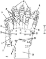
- Fig. 1A is a stereogram of illustrating a wearable finger rehabilitation apparatus in accordance with the present invention.
- a wearable finger rehabilitation apparatus 1 of the present invention includes a thumb mechanism 10, a plurality of finger mechanisms 20, a pinky finger mechanism 30 and a palm base 50.
- the thumb mechanism 10, the plurality of finger mechanisms 20 and the pinky finger mechanism 30 are respectively fixed onto one end of the palm base 50.
- the thumb mechanism 10 is connected by a joint connecting part 51 in a L-shaped like structure with respect to the palm base 50, so that the thumb mechanism 10 is at a plane which is different from one at which the plurality of finger mechanisms 20 and the pinky finger mechanism 30 are for complying with the human body construction/ergonomics.
- the arrangement that the thumb mechanism 10, the plurality of finger mechanisms 20 and the pinky finger mechanism 30 are respectively fixed to a L-shaped like structure of the joint connecting part 51, and the palm base 50 may enable the thumb mechanism 10 to bend freely in the different direction.
- the L-shaped like structure formed by the palm base 50 and the joint connecting part 51 not only makes the user's five fingers easy to wear the wearable finger rehabilitation apparatus 1 but also prevents the thumb mechanism 10 from interrupting the plurality of finger mechanisms 20 and the pinky finger mechanism 30 in bending.
- the palm base 50 and the joint connecting part 51 are fixedly connected with a thumb bottom bar 15 of the thumb mechanism 10, a plurality of finger bottom bars 26 of the plurality of finger mechanisms 20 and a portion of pinky bottom bars 36 (as shown in Fig. 1B ) of the pinky finger mechanism 30, and a connection way is illustrated in Fig. 1B .
- a linear direct drive motors 11, 21, 31 are respectively equipped to the thumb bottom bar15, each one of the finger bottom bars 26, and the pinky bottom bar 36 on the palm base 50 and the joint connecting part 51.
- each one of the bottom bars of finger 26, and the bottom bar of pinky finger 36 are connected to the thumb mechanism 10, the plurality of finger mechanisms 20 and the pinky finger mechanism 30, respectively.
- the thumb mechanism 10, the plurality of finger mechanisms 20, and the pinky finger mechanism 30 are arranged at outside of the palm base 50 and the joint connecting part 51.
- Fig. 1B is a bottom view of a wearable finger rehabilitation apparatus in accordance with the present invention. Shown in Fig. 1B , the palm base 50 and the joint connecting part 51 are respectively fixed with the thumb bottom bar 15, a portion of the plurality of finger bottom bars 26, and a portion of the pinky bottom bar 36 with a plurality of locking members 53, 54. Next, the thumb bottom bar 15 and the plurality of finger bottom bars 26 and the portion of the pinky bottom bar 36 are exposed to outsides the palm base 50 and the joint connecting part 51.
- thumb bottom bar 15, the plurality of finger bottom bars 26 and the pinky bottom bar 36 which extending outside the palm base 50 and the joint connecting part 51, are connected to the thumb mechanism 10, the plurality of finger mechanisms 20, and the pinky finger mechanism 30 respectively, so as to enable the thumb mechanism 10, the plurality of finger mechanisms 20, and the pinky finger mechanism 30 act in space outside the palm base 50 and the joint connecting part 51.
- thumb bottom bar 15, the plurality of finger bottom bars 26, and the pinky bottom bar 36 are fixedly connected together with the palm base 50 and the joint connecting part 51 via the locking members 53, 54.
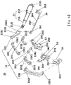
- Fig. 2 is an exploded drawing of illustrating a thumb mechanism in accordance with the present invention, and dash lines in Fig. 2 shows the connecting relationship among each component.
- the thumb mechanism 10 includes a thumb linear direct drive motor 11, a thumb connecting bar drive shaft 12, a thumb metacarpophalangeal joints mechanism 13, and a thumb-finger mechanism 14.
- the thumb linear direct drive motor 11 includes a thumb motor shaft 111 and a thumb motor device 112.
- the thumb motor shaft 111 is arranged within the thumb motor device 112 and driven by the thumb motor device 112 to move forward and backward.
- a thumb pivot hole 1111 i.e.
- the motor pivot hole of front on the thumb mechanism 10) is deposited at a front end of the thumb motor shaft 111, and a thumb motor pivot hole 1121 (i.e. the rear pivot hole of motor on the thumb mechanism 10) is deposited at a rear end of the thumb motor device 112.
- the thumb connecting bar drive shaft 12 includes a thumb drive bar 122, a thumb first connecting bar 121 and a thumb second connecting bar 123.
- the thumb pivot hole 1221 i.e. the sixth pivot hole on the thumb mechanism 10) is positioned at a front end of the thumb drive bar 122, and a thumb pivot hole 1222 (i.e.
- the seventh pivot hole on the thumb mechanism 10) for connecting the thumb pivot hole 1111 on the thumb motor shaft 111 is positioned at a rear end of the thumb drive bar 122.
- a thumb pivot hole 1211(i.e. the first pivot hole on the thumb mechanism 10) is positioned at a front end of the thumb first connecting bar 121
- a thumb pivot hole 1212 i.e. the second pivot hole on the thumb mechanism 10) is positioned near a middle part of the thumb first connecting bar 121.
- the thumb pivot hole 1212 is configured to connect the thumb pivot hole 1222 at the rear end of the thumb drive bar 122 and the thumb pivot hole 1111 on the thumb motor shaft 111.
- a thumb pivot hole 1213 i.e.
- the third pivot hole on the thumb mechanism 10) is positioned at a rear end of the first thumb connecting bar 121.
- a thumb pivot hole 1231 i.e. the fourth pivot hole on the thumb mechanism 10) and a thumb pivot hole 1232 (i.e. the fifth pivot hole on the thumb mechanism 10) are deposited at a front end and a rear end of the thumb second connecting bar 123, respectively.
- the thumb pivot hole 1232 is configured to connect to the thumb pivot hole 1211 at the front end of the thumb first connecting bar 121.
- a length of the thumb second connecting bar 123 is longer than that of the thumb first connecting bar 121.
- the thumb metacarpophalangeal joints mechanism 13 is arranged on the thumb mechanism 10 and is an inverse U-shaped like structure which provides open space for accommodating a thumb of the user (not shown in the drawing).
- a pair of thumb pivot holes 131(i.e. the eighth pivot hole on the thumb mechanism 10) is deposited at a front end of the thumb metacarpophalangeal joints mechanism 13, and another thumb pivot hole 132 (i.e. the ninth pivot hole on the thumb mechanism 10) is arranged at an upper end of the inverse U-shaped like structure.
- the thumb pivot hole 132 is configured to connect the thumb pivot hole 1221 at the front end of the thumb drive bar 122.
- the thumb mechanism 10 further includes a thumb-finger mechanism 14, and the thumb-finger mechanism 14 is also an inverse U-shaped like structure so as to have open space for accommodating the user's thumb (not shown).
- a thumb pivot hole 141 i.e. the tenth pivot hole on the thumb mechanism 10) arranged at an upper end of the inverse U-shaped like structure is used to connect the thumb pivot hole 1231 at the front end of the thumb second connecting bar 123.
- a thumb pivot hole 142(i.e. the eleventh pivot hole on the thumb mechanism 10) arranged at a back end of the thumb-finger mechanism 14 is used to connect one thumb pivot hole 131 at the front end of the thumb metacarpophalangeal joints mechanism 13.
- the thumb mechanism 10 further includes a thumb bottom bar 15, and the thumb bottom bar 15 with thumb through holes 153, 154 is fixed onto the palm base 50 and the joint connecting part 51 by the locking members 53, 54 (as shown in Fig. 1B ).
- a thumb pivot hole 151 i.e. the front pivot hole on the thumb mechanism 10) arranged at a front end of the thumb bottom bar 15 is used to connect the thumb pivot hole 1213 at the rear end of the thumb first connecting bar 121.
- a thumb pivot hole 152 formed at a rear end of the thumb bottom bar 15 is configured to connect the thumb motor pivot hole 1121 at the rear end of the thumb motor device 112. It is noted that a link point connecting the thumb pivot hole 152 (i.e.
- the wearable finger rehabilitation apparatus 1 of the present invention may have modular designs for different sizes of the thumb mechanism 10 to suit various sizes of the user's thumb for improving the comfort in wearing and rehabilitation effect with the suitable sizes of the rehabilitation apparatus. It is noted that the connection of the thumb through holes 153, 154 and the locking members 53, 54 is implemented by screws.
- the volume of the thumb through holes 153, 154 may be used to adjust the position of the thumb mechanism 10 on the joint connecting part 51 when the locking members 53, 54 are mounted into the thumb through holes 153, 154.
- radial angles of the thumb mechanism 10 on the palm can be also adjusted according to the physiological structure of user's palm to make the user wear comfortably.
- Fig. 3 is a flow chart of illustrating motion (thumb bending) of a thumb mechanism in accordance with the present invention.
- Step S1 in the case of the thumb mechanism 10 applying onto the user's thumb in a straightened state (not shown in the drawings), the thumb motor shaft 111 may change the position of the thumb mechanism 10 by moving forward and simultaneously drive the thumb first connecting bar 121 and the thumb drive bar 122 which are connected to the thumb motor shaft 111 respectively to perform the bending motion.
- the thumb linear direct drive motor 11 moves upward and downward along with the angle of the bending of the thumb mechanism 10 by utilizing the thumb motor pivot hole 1121 as a fulcrum.
- Step S2 when the thumb drive bar 122 moves, the thumb metacarpophalangeal joints mechanism 13 connected to the thumb drive bar 122 may be driven to rotate at the same time.
- the thumb metacarpophalangeal joints mechanism 13 rotates, user's thumb metacarpophalangeal (MCP) joint can rotate together (to result in the thumb bending).
- MCP thumb metacarpophalangeal
- the rotation of the thumb first connecting bar 121 may simultaneously drive the thumb second connecting bar 123 which is connected to the thumb first connecting bar 121 to be rotated.
- Step S3 in the case of the rotation of the thumb metacarpophalangeal joints mechanism 13, and the thumb drive bar 122 reaches to a critical situation (for example, user's thumb metacarpophalangeal joints stops rotating) but the thumb motor shaft 111 still moves forward, the rotation of the thumb-finger mechanism 14 is driven and implemented by the rotation of the thumb first connecting bar 121 and the thumb second connecting bar 123.
- the rotation of the thumb-finger mechanism 14 may simultaneously drive the interphalangeal joint (IP joint) of user's thumb to rotate (to result in the thumb bending).
- Step S4 the thumb-finger mechanism 14 stops rotating when the thumb motor shaft 111 stops moving forward.
- FIG. 4 is a schematic of illustrating bending of the thumb mechanism in accordance with the present invention. Please refer to Fig. 4 with reference of acting steps aforementioned, the bending motion of the user's thumb driven by the thumb mechanism 10 is performed along with a stable motion of the thumb motor shaft 111. Consequently, the possibly physical damage on the user's thumb made by the motion of those mechanisms aforementioned may be reduced because the bending of the thumb mechanism 10 is controlled within limited displacements.
- Fig. 5 is a flow chart of illustrating motion (thumb straighten) of a thumb mechanism in accordance with the present invention.
- the thumb motor shaft 111 may change the position of the thumb mechanism 10 by moving backward, and may simultaneously drive the thumb first connecting bar 121 and the thumb drive bar 122 which are connected to the thumb motor shaft 111 respectively to perform the straighten motion.
- the thumb linear direct drive motor 11 moves upward and downward along with the angle of the extension of the thumb mechanism 10 by utilizing the thumb motor pivot hole 1121 as a fulcrum.
- Step S6 when the thumb drive bar122 rotates, the thumb metacarpophalangeal joints mechanism 13 connected to the thumb drive bar 122 may be driven to rotate at the same time, and the thumb motor shaft 111 also rotates with respect to the thumb bottom bar 15 so as to drive the MCP joint of user's thumb to be rotated (make the thumb straightly). Furthermore, the rotation of the thumb first connecting bar 121 may simultaneously drive the thumb second connecting bar 123 that is connected to the thumb first connecting bar 121 to rotate.
- Step S7 in the case of the rotation of the thumb metacarpophalangeal joints mechanism 13, and the thumb drive bar 122 reaches to a critical situation (for example, user's thumb metacarpophalangeal joints stops rotating) but the thumb motor shaft 111 still moves forward, the rotation of the thumb-finger mechanism 14 is driven and implemented by the rotation of the thumb first connecting bar 121 and the thumb second connecting bar 123.
- the rotation of the thumb-finger mechanism 14 may simultaneously drive the user's thumb interphalangeal joint to rotate (to result in the thumb straighten).
- Step S8 the thumb-finger mechanism 14 stops moving when the thumb motor shaft 111 stops moving forward.
- the rotation of the user's interphalangeal joint also stops, and the gesture of user's thumb is changed from the bending state into a straighten state to reach the purpose of straightening the user's thumb.
- the straighten motion of the user's thumb driven by the thumb mechanism 10 is performed along with a stable motion of the thumb motor shaft 111. Consequently, the possibly physical damage on the user's thumb made by the actions of those mechanisms aforementioned may be reduced because the straighten of the thumb mechanism 10 is controlled within limited displacements.
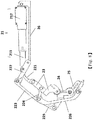
- Fig. 6 is an exploded drawing of illustrating a finger mechanism in accordance with the present invention, and dash lines in Fig. 6 shows the linking among plural components.
- the finger mechanism 20 includes index finger, middle finger, and ring finger.
- the finger mechanism 20 includes a finger linear direct drive motor 21 and a finger connecting bar drive shaft 22.
- the finger linear direct drive motor 21 includes a finger motor shaft 211 and a finger motor device 212.
- a finger motor pivot hole 2111 i.e. the motor pivot hole of front on the finger mechanism 20
- a finger motor pivot hole 2121 i.e.
- the finger connecting bar drive shaft 22 includes a finger first drive bar 221 and a finger first connecting bar 222, a finger second connecting bar 223, a finger second drive bar 224, a finger third drive bar 225, and a finger third connecting bar 226.
- a finger pivot hole 2211 i.e. the seventh pivot hole on the finger mechanism 20
- a finger pivot hole 2212 i.e. the eighth pivot hole on the finger mechanism 20
- for connecting the finger motor pivot hole 2111 is positioned at a rear end of the finger first drive bar 221.
- the finger first drive bar 221 has an arc design and dimensions of the arc design may be selected for controlling a whole length of the finger mechanism 20, depending on length of user's fingers.
- a finger pivot hole 2221(i.e. the first pivot hole on the finger mechanism 20) is positioned at a front end of the finger first connecting bar 222, and a finger pivot hole 2222(i.e. the second pivot hole on the finger mechanism 20) is positioned near a middle part of the finger first connecting bar 222.
- the finger pivot hole 2222 is configured to connect the finger motor pivot hole 2111 and the finger pivot hole 2212.
- a finger pivot hole 2223 (i.e. the third pivot hole on the finger mechanism 20) is positioned at a rear end of the finger first connecting bar 222.
- a finger pivot hole 2231 (i.e. the fourth pivot hole on the finger mechanism 20) is deposited at a front end of the finger second connecting bar 223, and a finger pivot hole 2232(i.e. the fifth pivot hole on the finger mechanism 20) is at a rear end of the finger second connecting bar 223 for connecting the finger pivot hole 2221.
- a finger pivot hole 2241 (i.e. the ninth pivot hole on the finger mechanism 20) is deposited at a front end of the finger second drive bar 224 for connecting the finger pivot hole 2231.
- a finger pivot hole 2242 (i.e. the tenth pivot hole on the finger mechanism 20) is arranged at a rear end of the finger second drive bar 224.
- a finger pivot hole 2251 (i.e.
- the eleventh pivot hole on the finger mechanism 20 is arranged at a front end of the finger third drive bar 225.
- a finger pivot hole 2252 for connecting the finger pivot hole 2231 and the finger pivot hole 2241 is deposited at a rear end of the finger third drive bar 225.
- a finger pivot hole 2261 i.e. the twenty-first pivot hole on the finger mechanism 20
- a finger pivot hole 2262 is deposited at a rear end of the finger third connecting bar 226 and is configured to connect the finger pivot hole 2252(i.e.
- a length of the finger third connecting bar 226 is longer than that of the finger first connecting bar 222 and the finger second connecting bar 223.
- the finger mechanism 20 further includes a finger metacarpophalangeal mechanism 23, a finger proximal phalanx mechanism 24, a finger distal phalanx mechanism 25, and a finger bottom bar 26.
- the finger metacarpophalangeal mechanism 23 is an inverse U-shaped like structure which provides open space for accommodating the user's fingers (not shown).
- a finger connecting part 230 is arranged at a front end of the finger metacarpophalangeal mechanism 23 and extends downward a distance.
- a pair of finger pivot holes 231 i.e. the thirteenth pivot hole on the finger mechanism 20
- a finger pivot hole 232 (i.e.
- the fourteenth pivot hole on the finger mechanism 20 is deposited near a middle part of the finger metacarpophalangeal mechanism 23 and is configured to connect the finger pivot hole 2242.
- a finger pivot hole 233 i.e. the fifteenth pivot hole on the finger mechanism 20
- the finger proximal phalanx mechanism 24 is also an inverse U-shaped like structure so as to have an open space for accommodating the user's fingers (not shown in the drawing).
- a finger pivot hole 241(i.e. the sixteenth pivot hole on the finger mechanism 20) is deposited at a front end of the finger proximal phalanx mechanism 24.
- a finger pivot hole 243 (i.e. the seventeenth pivot hole on the finger mechanism 20) deposited at a rear end of the finger proximal phalanx mechanism 24 is used to connect the finger pivot hole 231. Furthermore, a finger shaft member 240 is positioned on a top of an inverse U-shaped structure between the front and the rear ends of the finger proximal phalanx mechanism 24 and extends upward to a distance. A finger pivot hole of 242(i.e. the eighteenth pivot hole on the finger mechanism 20) on one end of the finger shaft member 240 is used to connect a finger pivot hole 2251.
- the finger distal phalanx mechanism 25 is also an inverse U-shaped like structure so as to have an open space for accommodating the user's fingers (not shown in the drawing).
- a finger pivot hole 251 i.e. the nineteenth pivot hole on the finger mechanism 20
- a pair of finger pivot holes 252 i.e. the twentieth pivot hole on the finger mechanism 20
- the pair of finger pivot holes 252 is used to connect the finger pivot hole 241.
- a finger bottom bar 26 with a pair of finger through holes 263, 264 is fixed onto the palm base 50 by the locking members 53, 54 (shown as Fig. 1B ).
- a pivot hole 261(i.e. the front pivot hole on the finger mechanism 20) is arranged at a front end of the finger bottom bar 26, and is used to connect the finger pivot hole 2223.
- a finger pivot hole 262(i.e. the rear pivot hole on the finger mechanism 20) deposited at a rear end of the finger bottom bar 26 is used to connect the finger motor pivot hole 2121, so that the finger linear direct drive motor 21 may be mounted onto the finger bottom bar 26.
- a link point for connecting the finger pivot hole 262 and the finger motor pivot hole 2121 may be a movable fulcrum to movably fix the finger linear direct drive motor 21 within the finger pivot hole of 262.
- the finger linear direct drive motor 21 may move forward and backward along with the finger motor shaft 211, and when the finger linear direct drive motor 21 drives the bending or straighten of the finger mechanism 20, the finger linear direct drive motor 21 may move upward and downward along with the angles of bending or straighten of finger mechanism 20.
- the finger mechanism 20 may be modularized by the connection of the bottom bar of finger 26 and mounted onto the palm base 50 by the locking members 53/54 (shown in Fig.1B ) as well as detached from the palm base 50.
- the wearable finger rehabilitation apparatus 1 of the present invention may have modular designs for different sizes of the finger mechanism 20 to suit various sizes of the user's thumb for improving the comfort in wearing and rehabilitation effect with the suitable sizes of the rehabilitation apparatus.
- the connection of the finger through holes 263, 264 and the locking members 53, 54 (shown in Fig. 1B ) is implemented by screws.
- the volume of finger through holes 263, 264 may be used to adjust the position of the finger mechanisms 20 on the palm base 50 when the locking members 53, 54 are mounted into the finger through holes 263, 264.
- radial angles of the finger mechanisms 20 on the palm can be also adjusted according to physiological structure of the user's palm o to make the user wear comfortably.
- Fig.7 is a flow chart illustrating motion (finger bending) of a finger mechanism in accordance with the present invention.
- Step SS1 in the case of the finger mechanism 20 applying onto the user's finger in a straighten state (not shown in the drawings), the finger motor shaft 211 may change the position of the finger mechanism 20 by moving forward, and simultaneously drive the finger first connecting bar 222 and the finger first drive bar of 221 which are connected to the finger motor shaft 211 to perform the bending motion.
- the finger linear direct drive motor 21 moves upward and downward along with the angle of the bending of the finger mechanism 20 by utilizing the finger motor pivot hole 2121 as a fulcrum.
- Step SS2 when the finger first drive bar 221 rotates, the finger metacarpophalangeal mechanism 23 may be driven to rotate at the same time.
- the finger metacarpophalangeal mechanism 23 rotates, user's finger MCP joint can be driven to rotate (to result in the finger bending).
- the rotation of the finger first connecting bar 222 may simultaneously drive the finger second connecting bar 223 to rotate.
- Step SS3 when the finger second connecting bar 223 rotates, the finger second drive bar 224, which is connected to the finger second connecting bar 223, can be driven to rotate.
- Step SS4 the rotations of the finger second connecting bar 223 and the finger second drive bar 224 drive the finger third drive bar 225 to rotate.
- Step SS5 when the finger third drive bar 225 rotates, it may drive the finger proximal phalanx mechanism 24 to rotate. Moreover, the rotation of the finger proximal phalanx mechanism 24 may drive user's proximal phalange joint to rotate (to result in the finger bending).
- Step SS6 the rotation of the finger third drive bar 225 further drives the finger third connecting bar 226 to rotate.
- Step SS7 when the finger third connecting bar 226 rotates, it may drive the finger distal phalanx mechanism 25 to rotate. And when the finger distal phalanx mechanism 25 rotates, it may drive user's distal phalange joint to rotate (to result in the finger bending).
- Step SS8 once the finger motor shaft 211 stops moving forward, the rotations of aforementioned components within the finger mechanism 20 can also stop. Consequently, the user's fingers earlier in straighten state are changed to bending state, and the purpose of bending finger of user is achieved, shown in Fig. 8 that is a schematic of illustrating bending of a finger mechanism in accordance with the present invention.
- the bending motion of the user's fingers driven by the finger mechanism 20 is performed along with a stable motion of the finger motor shaft 211. Consequently, possibly physical damage on the user's finger made by the motions of those mechanisms aforementioned may be reduced because the bending of the finger mechanism 20 is controlled within limited displacements.
- Fig. 9 is a flow chart of illustrating the motion (finger straighten) of a finger mechanism in accordance with the present invention.
- the finger motor shaft 211 may change the position of the finger mechanism 20 by backward moving and simultaneously drive the finger first connecting bar 222 and the finger first drive bar 221 which are connected to the finger motor shaft 211 to perform the straighten motion.
- the finger linear direct drive motor 21 moves upward and downward along with the angle of the straighten of the finger mechanism 20 by utilizing the finger motor pivot hole 2121 (as shown in Fig.
- Step SS10 when the finger first drive bar of 221 rotates, the finger metacarpophalangeal mechanism 23 may rotate together at the same time, and to drive the user's MCP joint to rotate (for example, finger straighten). Besides, the rotation of the finger first connecting bar 222 may drive the finger second connecting bar 223 to rotate.
- Step SS11 when the finger second connecting bar 223 rotates, the finger second drive bar of 224 which is connected to the finger second connecting bar 223 is driven to rotate.
- Step SS12 the finger second connecting bar 223 and the finger second drive bar 224 can drive the finger third drive bar 225 to rotate.
- Step SS 13 when the finger third drive bar 225 rotates, it can drive the finger proximal phalanx mechanism 24 to rotate, and the rotation of the finger proximal phalanx mechanism 24 can further drive user's proximal phalange joint to rotate (for example, finger straighten).
- Step SS14 the finger third drive bar 225 further drives the finger third connecting bar 226 to rotate.
- Step SS15 when the finger third connecting bar 226 rotates, it can drive the finger distal phalanx mechanism 25 to rotate, and the rotation of the finger distal phalanx mechanism 25 can further drive the user's distal phalange joint to rotate (e.g. extension of finger).
- Step SS16 when the finger motor shaft 211 stops moving forward, the finger distal phalanx mechanism 25 stops rotating, too, as well as the user's distal phalange joint. Consequently, the user's finger in bending state currently is changed into straighten state to achieve purpose of straighten of the user's finger.
- the straighten motion of the user's finger driven by the finger mechanism 20 is performed along with a stable motion of the finger motor shaft 211. Consequently, possibly physical damage on the user's finger made by the motions of those mechanisms aforementioned may be reduced because the extension of the finger mechanism 20 is controlled within limited displacements.
- the pinky finger mechanism 30 of the present invention is identical to the finger mechanism 20, so detail constructions, bending or extension process are also referred to Figs. 6-9 , and we will not be repeated therein.
- the position of the pinky finger mechanism 30 equipped onto the palm base 50 is designed in the wearable finger rehabilitation apparatus 1 to meet the finger characteristics of the user, so the position of the pinky finger mechanism 30 will be illustrated in following paragraphs.
- Fig. 10 is a schematic of showing a pinky finger mechanism arranged on a palm base in accordance with the present invention.
- the palm base 50 is equipped with the thumb mechanism 10, the three finger mechanisms 20, and the pinky finger mechanism 30.
- the three finger mechanisms 20 and the pinky finger mechanism 30 on the palm base 50 are in a radial arrangement of small angles but there is a bigger gap between the pinky finger mechanism 30 and the adjacent three finger mechanisms 20. That is, the pinky finger mechanism 30 is positioned at an offset angle ⁇ outward with respect to the palm base 50, and the offset angle ⁇ is defined by two staggered dash lines 40.
- the offset angle ⁇ from 5 ⁇ 15 degrees generally, may be designed depending on palm shape of user.
- the offset angle design for the pinky finger mechanism 30 is to increase degrees of freedom of radial arrangement between the four fingers (that is the three finger mechanisms 20 and the pinky finger mechanism 30), which may make user wear comfortably, as well as rehabilitation enhancement with suitable sizes design of thumb mechanism and of finger mechanisms.
- Fig. 11 is a schematic of showing an abduction design of the pinky finger mechanism in accordance with the present invention. Shown in Fig. 11 , the thumb mechanism 10, the three finger mechanisms 20, and the pinky finger mechanism 30 are arranged on the palm base 50. There is a displacement distance "d" from 1mm to 10 mm between a motor shaft center line 41a of the linear direct drive motor 31 on the pinky finger mechanism 30 and a center line 41b of the pinky first connecting bar 32 on the pinky finger mechanism 30. It is noted that the pinky first connecting bar 32 is same as the finger first connecting bar 222 (as shown in Fig. 6 ) on the finger mechanism 20 in a situation aforementioned.
- the abduction design may further increase the degrees of freedom of the radial arrangement among the four fingers to make user wear comfortably, as well as rehabilitation enhancement.
- the wearable finger rehabilitation apparatus 1 of the present invention may have modular designs for different sizes of the thumb mechanism 10, three finger mechanisms 20, and the pinky finger mechanism 30 to suit various sizes of the user's hand for improving the comfort in wearing and rehabilitation effect with suitable sizes of rehabilitation apparatus.
- the abduction angle between the modular pinky finger mechanism 30 and the adjacent modular finger mechanism 20 can be adjusted according to the size of the palm of user, which may increase the degrees of freedom of radial arrangement of the four fingers (that is the three finger mechanisms 20 and the pinky finger mechanism 30), makes user wear comfortably, and enhances rehabilitation effect with suitable sizes.
- the modular thumb mechanism 10 is arranged to connect to the joint connecting part 51 to form a L-shaped like structure that enables the thumb mechanism 10, the three finger mechanisms 20 and the pinky finger mechanism 30 to be fixed at different planes for complying with nature construction/ergonomics of human body.
- the thumb mechanism 10 When the thumb mechanism 10, the three finger mechanisms 20 and the pinky finger mechanism 30 are respectively fixed to the L-shaped like structure formed by the palm base 50 and the joint connecting part 51, the thumb mechanism 10 may bend freely at another direction.
- the L-shaped like structure formed by the palm base 50 and the joint connecting part 51 not only makes the user's hand easily applied on the wearable finger rehabilitation apparatus 1 but also prevents the thumb mechanism 10 from interfering the finger mechanism 20 and the pinky finger mechanism 30 in bending. Consequently, the most rehabilitation effects for user can be achieved with the use of the modular wearable finger rehabilitation apparatus 1 of the present invention because of its optimization design, easy wearable, adjustable, comfortable characteristics, and safety with use of linear direct drive motor.
- thumb linear direct drive motor 11 and the finger linear direct drive motor 21 on the modular wearable finger rehabilitation apparatus 1 may connect to a control device (not shown) with cables, or via wireless network, so that thumb linear direct drive motor 11 and the finger linear direct drive motor 21 on the modular wearable finger rehabilitation apparatus 1 may be controlled by receiving instructions from the control device to execute the rehabilitation of respective finger or whole palm.
- a control device not shown
- thumb linear direct drive motor 11 and the finger linear direct drive motor 21 on the modular wearable finger rehabilitation apparatus 1 may be controlled by receiving instructions from the control device to execute the rehabilitation of respective finger or whole palm.
- how the wearable finger rehabilitation apparatus 1 to be controlled by receiving instructions from the control device to execute the rehabilitation of respective finger or whole palm is not limited in the present invention.
- linear direct drive motors in aforementioned or relative embodiments may be equipped with the selective motor shaft of electrical or hydraulic type, or threaded-driving type with threads to implement moving forward and backward along a single axis, which is not limited to a specific type.
- power needed for the linear direct drive motors may be battery, mobile power supply or plugging type, which is not limited to a specific one in the present invention.
Landscapes
- Health & Medical Sciences (AREA)
- Physical Education & Sports Medicine (AREA)
- Epidemiology (AREA)
- Pain & Pain Management (AREA)
- Engineering & Computer Science (AREA)
- Rehabilitation Therapy (AREA)
- Life Sciences & Earth Sciences (AREA)
- Animal Behavior & Ethology (AREA)
- General Health & Medical Sciences (AREA)
- Public Health (AREA)
- Veterinary Medicine (AREA)
- Mechanical Engineering (AREA)
- Robotics (AREA)
- Rehabilitation Tools (AREA)
Applications Claiming Priority (1)
| Application Number | Priority Date | Filing Date | Title |
|---|---|---|---|
| TW105144118A TWI620559B (zh) | 2016-12-30 | 2016-12-30 | 穿戴式手指復健裝置 |
Publications (3)
| Publication Number | Publication Date |
|---|---|
| EP3357473A2 true EP3357473A2 (de) | 2018-08-08 |
| EP3357473A3 EP3357473A3 (de) | 2018-11-07 |
| EP3357473B1 EP3357473B1 (de) | 2021-08-25 |
Family
ID=60813702
Family Applications (1)
| Application Number | Title | Priority Date | Filing Date |
|---|---|---|---|
| EP17210786.4A Active EP3357473B1 (de) | 2016-12-30 | 2017-12-28 | Am körper tragbare fingerrehabilitationsvorrichtung |
Country Status (4)
| Country | Link |
|---|---|
| US (1) | US10940073B2 (de) |
| EP (1) | EP3357473B1 (de) |
| JP (1) | JP6611785B2 (de) |
| TW (1) | TWI620559B (de) |
Cited By (3)
| Publication number | Priority date | Publication date | Assignee | Title |
|---|---|---|---|---|
| CN109350457A (zh) * | 2018-12-19 | 2019-02-19 | 合肥工业大学 | 一种气动肌肉-弹簧变刚度驱动的手部康复训练装置 |
| CN110051508A (zh) * | 2019-05-31 | 2019-07-26 | 山东海天智能工程有限公司 | 一种康复训练用四指驱动机构 |
| CN110664588A (zh) * | 2019-09-30 | 2020-01-10 | 东南大学 | 一种刚柔耦合结构的脑卒中患者手部功能康复机器人 |
Families Citing this family (20)
| Publication number | Priority date | Publication date | Assignee | Title |
|---|---|---|---|---|
| BR112018016609B1 (pt) * | 2016-02-15 | 2023-01-24 | Lime Medical Gmbh | Dispositivo de terapia para realizar um movimento sustentado, passivo e/ou ativamente assistido dos dedos e do polegar da mão de um paciente |
| US11400009B2 (en) * | 2017-10-24 | 2022-08-02 | Indian Institute Of Technology Delhi | Exoskeleton device for upper limb rehabilitation |
| CN109223442B (zh) * | 2018-09-25 | 2020-02-18 | 上海交通大学 | 外骨骼式七自由度康复机械手 |
| CN109549819B (zh) * | 2018-11-13 | 2020-11-24 | 东南大学 | 手掌支撑式手指康复训练装置及使用方法 |
| JP7149208B2 (ja) * | 2019-03-14 | 2022-10-06 | 川崎重工業株式会社 | ロボットの関節構造体 |
| CN109771222A (zh) * | 2019-03-27 | 2019-05-21 | 燕山大学 | 一种具有内收外展功能的手指康复机器人 |
| CN109893400B (zh) * | 2019-04-17 | 2024-04-05 | 北京因时机器人科技有限公司 | 一种用于外骨骼手部康复机器人的手指屈伸运动机构 |
| CN109893831A (zh) * | 2019-04-20 | 2019-06-18 | 南通大学 | 基于三个四杆机构的手指康复训练装置 |
| DE102019112049B4 (de) | 2019-05-08 | 2021-01-28 | Universitätsmedizin Der Johannes Gutenberg-Universität Mainz | Finger-Bewegungsschiene zur Durchführung einer kontinuierlichen, passiven und/oder aktiv-assistierten Bewegung eines Fingers und/oder eines Daumens eines Patienten, sowie Therapiegerät umfassend eine solche Finger-Bewegungsschiene |
| USD942023S1 (en) * | 2019-10-21 | 2022-01-25 | Neofect Co., Ltd. | Hand rehabilitation training apparatus |
| CN110916884B (zh) * | 2019-12-03 | 2021-07-13 | 重庆万州川东骨科医院有限公司 | 一种爪型手治疗器 |
| CN111631904B (zh) * | 2020-05-28 | 2022-06-17 | 河海大学常州校区 | 一种半穿戴式手掌康复外骨骼 |
| CN112076066B (zh) * | 2020-09-16 | 2022-08-30 | 青岛市中心医院 | 一种骨科滑膜炎患者术后手指恢复装置 |
| US20240009059A1 (en) | 2020-11-27 | 2024-01-11 | Meltin Mmi Co., Ltd. | Program and system for controlling device for assisting movement of part of interest of subject, and method for configuring device for assisting movement of part of interest of subject |
| CN113332097B (zh) * | 2021-06-04 | 2022-10-25 | 燕山大学 | 一种可远端驱动的柔性四指康复机器人 |
| CN113855482B (zh) * | 2021-09-30 | 2022-07-01 | 中国科学院自动化研究所 | 基于球面连杆机构的手部康复装置、手部拇指控制装置 |
| MX2021013325A (es) * | 2021-10-29 | 2023-05-01 | Paola Aralid Izaguirre Perez | Sistema tipo exoesqueleto para ortesis y protesis de falanges de la mano. |
| CN114470666A (zh) * | 2022-02-21 | 2022-05-13 | 山东海天智能工程有限公司 | 一种手功能康复训练系统大拇指驱动机构 |
| CN114770569B (zh) * | 2022-03-25 | 2023-12-12 | 北京邮电大学 | 一种多自由度模块化手指及模块化可重构多指灵巧手 |
| TWI832791B (zh) * | 2023-08-15 | 2024-02-11 | 高雄醫學大學 | 連續式手指被動關節運動器 |
Citations (1)
| Publication number | Priority date | Publication date | Assignee | Title |
|---|---|---|---|---|
| CN102811690B (zh) | 2010-03-23 | 2016-11-09 | 伊德洛有限公司 | 手康复装置 |
Family Cites Families (14)
| Publication number | Priority date | Publication date | Assignee | Title |
|---|---|---|---|---|
| TWI374734B (en) * | 2009-05-19 | 2012-10-21 | Nat Univ Chung Hsing | Finger moving device and its using method |
| US8574178B2 (en) * | 2009-05-26 | 2013-11-05 | The Hong Kong Polytechnic University | Wearable power assistive device for helping a user to move their hand |
| US8177856B2 (en) * | 2009-12-28 | 2012-05-15 | Edward Jaworski | Humanlike mechanical finger for prostethic hands and massaging device with humanlike mechanical fingers |
| WO2012120393A2 (en) * | 2011-03-04 | 2012-09-13 | Koninklijke Philips Electronics N.V. | Device for hand rehabilitation |
| TWI412354B (zh) * | 2011-09-27 | 2013-10-21 | Univ Nat Cheng Kung | 手指復健裝置 |
| DE102012002785B4 (de) * | 2012-02-15 | 2017-06-01 | Festo Ag & Co. Kg | Orthese |
| US9532916B2 (en) * | 2012-03-30 | 2017-01-03 | Rehab-Robotics Company Limited | Wearable power assistive device for hand rehabilitation |
| KR101485414B1 (ko) * | 2013-05-03 | 2015-01-26 | 국립대학법인 울산과학기술대학교 산학협력단 | 가상 물체와의 상호작용을 위한 손 외골격 링크 구조체 |
| KR101546882B1 (ko) * | 2013-09-06 | 2015-08-24 | 동의대학교 산학협력단 | 착용형 상지 재활 훈련장치 |
| KR101682949B1 (ko) * | 2014-05-12 | 2016-12-07 | 울산과학기술원 | 손 외골격 구조를 위한 힘 제어 구동기 모듈 및 이를 이용한 손 외골격 시스템 |
| TWI541011B (zh) * | 2014-09-30 | 2016-07-11 | Kai Zhang | Hand rehabilitation training device |
| WO2016077872A1 (en) * | 2014-11-21 | 2016-05-26 | Curtin University Of Technology | An orthosis |
| TWI532520B (zh) * | 2014-12-02 | 2016-05-11 | Finger rehabilitation device | |
| KR101541082B1 (ko) * | 2015-01-23 | 2015-08-03 | 주식회사 네오펙트 | 손 재활 운동 시스템 및 방법 |
-
2016
- 2016-12-30 TW TW105144118A patent/TWI620559B/zh active
-
2017
- 2017-12-21 JP JP2017244955A patent/JP6611785B2/ja active Active
- 2017-12-28 EP EP17210786.4A patent/EP3357473B1/de active Active
- 2017-12-28 US US15/857,131 patent/US10940073B2/en active Active
Patent Citations (1)
| Publication number | Priority date | Publication date | Assignee | Title |
|---|---|---|---|---|
| CN102811690B (zh) | 2010-03-23 | 2016-11-09 | 伊德洛有限公司 | 手康复装置 |
Cited By (6)
| Publication number | Priority date | Publication date | Assignee | Title |
|---|---|---|---|---|
| CN109350457A (zh) * | 2018-12-19 | 2019-02-19 | 合肥工业大学 | 一种气动肌肉-弹簧变刚度驱动的手部康复训练装置 |
| CN109350457B (zh) * | 2018-12-19 | 2020-11-24 | 合肥工业大学 | 一种气动肌肉-弹簧变刚度驱动的手部康复训练装置 |
| CN110051508A (zh) * | 2019-05-31 | 2019-07-26 | 山东海天智能工程有限公司 | 一种康复训练用四指驱动机构 |
| CN110051508B (zh) * | 2019-05-31 | 2021-02-26 | 山东海天智能工程有限公司 | 一种康复训练用四指驱动机构 |
| CN110664588A (zh) * | 2019-09-30 | 2020-01-10 | 东南大学 | 一种刚柔耦合结构的脑卒中患者手部功能康复机器人 |
| CN110664588B (zh) * | 2019-09-30 | 2021-11-02 | 东南大学 | 一种刚柔耦合结构的脑卒中患者手部功能康复机器人 |
Also Published As
| Publication number | Publication date |
|---|---|
| TWI620559B (zh) | 2018-04-11 |
| TW201822741A (zh) | 2018-07-01 |
| US10940073B2 (en) | 2021-03-09 |
| JP6611785B2 (ja) | 2019-11-27 |
| US20180185231A1 (en) | 2018-07-05 |
| EP3357473B1 (de) | 2021-08-25 |
| EP3357473A3 (de) | 2018-11-07 |
| JP2018108359A (ja) | 2018-07-12 |
Similar Documents
| Publication | Publication Date | Title |
|---|---|---|
| EP3357473A2 (de) | Am körper tragbare fingerrehabilitationsvorrichtung | |
| KR101485414B1 (ko) | 가상 물체와의 상호작용을 위한 손 외골격 링크 구조체 | |
| EP2239106B1 (de) | Roboterhand mit menschenähnlichen Fingern | |
| CN106923890B (zh) | 带有软爪和/或柔性腕机构的医疗器械 | |
| CN108261311B (zh) | 穿戴式手指复健装置 | |
| CN113101131B (zh) | 欠驱动康复机器人手指关节 | |
| US10264872B2 (en) | Wearable device | |
| CN113939386A (zh) | 机器人手爪以及机器人 | |
| US12090636B2 (en) | Robot hand device | |
| JP6373288B2 (ja) | ハンド機構 | |
| JP2011115248A (ja) | 装着型動作支援装置 | |
| CN115701943A (zh) | 手术工具和组件 | |
| CN115486944B (zh) | 一种主端操作装置和手术机器人 | |
| US20100280423A1 (en) | Muscle force assisting device (as amended) | |
| CN105832488A (zh) | 一种用于骨科手术控制台的主操作手串联机构 | |
| CN112118938A (zh) | 外骨骼手套 | |
| AU2020268487B2 (en) | Finger motion rail for carrying out a continuous, passive and/or actively assisted movement of a finger and/or a thumb of a patient, as well as a therapeutic device comprising a finger motion rail of this type | |
| KR102175274B1 (ko) | 휴머노이드 로봇에 구비된 핸드 | |
| KR20200118295A (ko) | 착용식 근력 보조 장치 | |
| JP2018167379A (ja) | 拇指機構およびこの拇指機構を組み込んだ人間型ハンド | |
| WO2023207737A1 (zh) | 线驱软体手套 | |
| JP2018167378A (ja) | 人間型ハンドにおける手首の回転構造 | |
| Zhou et al. | A Rotational Tri-fingered Gripper for Stable Adaptable Grasping | |
| Abbasi et al. | RoboGlove: Design of a Tendon-Driven Robotic Glove with Differential Mechanisms | |
| KR20170101552A (ko) | 파지 보조용 복합형 글로브 |
Legal Events
| Date | Code | Title | Description |
|---|---|---|---|
| PUAI | Public reference made under article 153(3) epc to a published international application that has entered the european phase |
Free format text: ORIGINAL CODE: 0009012 |
|
| STAA | Information on the status of an ep patent application or granted ep patent |
Free format text: STATUS: REQUEST FOR EXAMINATION WAS MADE |
|
| 17P | Request for examination filed |
Effective date: 20180517 |
|
| AK | Designated contracting states |
Kind code of ref document: A2 Designated state(s): AL AT BE BG CH CY CZ DE DK EE ES FI FR GB GR HR HU IE IS IT LI LT LU LV MC MK MT NL NO PL PT RO RS SE SI SK SM TR |
|
| AX | Request for extension of the european patent |
Extension state: BA ME |
|
| PUAL | Search report despatched |
Free format text: ORIGINAL CODE: 0009013 |
|
| AK | Designated contracting states |
Kind code of ref document: A3 Designated state(s): AL AT BE BG CH CY CZ DE DK EE ES FI FR GB GR HR HU IE IS IT LI LT LU LV MC MK MT NL NO PL PT RO RS SE SI SK SM TR |
|
| AX | Request for extension of the european patent |
Extension state: BA ME |
|
| RIC1 | Information provided on ipc code assigned before grant |
Ipc: A61H 1/02 20060101AFI20181002BHEP |
|
| RBV | Designated contracting states (corrected) |
Designated state(s): AL AT BE BG CH CY CZ DE DK EE ES FI FR GB GR HR HU IE IS IT LI LT LU LV MC MK MT NL NO PL PT RO RS SE SI SK SM TR |
|
| R17P | Request for examination filed (corrected) |
Effective date: 20180517 |
|
| GRAP | Despatch of communication of intention to grant a patent |
Free format text: ORIGINAL CODE: EPIDOSNIGR1 |
|
| STAA | Information on the status of an ep patent application or granted ep patent |
Free format text: STATUS: GRANT OF PATENT IS INTENDED |
|
| INTG | Intention to grant announced |
Effective date: 20210316 |
|
| GRAS | Grant fee paid |
Free format text: ORIGINAL CODE: EPIDOSNIGR3 |
|
| GRAA | (expected) grant |
Free format text: ORIGINAL CODE: 0009210 |
|
| STAA | Information on the status of an ep patent application or granted ep patent |
Free format text: STATUS: THE PATENT HAS BEEN GRANTED |
|
| AK | Designated contracting states |
Kind code of ref document: B1 Designated state(s): AL AT BE BG CH CY CZ DE DK EE ES FI FR GB GR HR HU IE IS IT LI LT LU LV MC MK MT NL NO PL PT RO RS SE SI SK SM TR |
|
| REG | Reference to a national code |
Ref country code: CH Ref legal event code: EP |
|
| REG | Reference to a national code |
Ref country code: IE Ref legal event code: FG4D Ref country code: AT Ref legal event code: REF Ref document number: 1423044 Country of ref document: AT Kind code of ref document: T Effective date: 20210915 |
|
| REG | Reference to a national code |
Ref country code: DE Ref legal event code: R096 Ref document number: 602017044643 Country of ref document: DE |
|
| REG | Reference to a national code |
Ref country code: LT Ref legal event code: MG9D |
|
| REG | Reference to a national code |
Ref country code: NL Ref legal event code: MP Effective date: 20210825 |
|
| REG | Reference to a national code |
Ref country code: AT Ref legal event code: MK05 Ref document number: 1423044 Country of ref document: AT Kind code of ref document: T Effective date: 20210825 |
|
| PG25 | Lapsed in a contracting state [announced via postgrant information from national office to epo] |
Ref country code: BG Free format text: LAPSE BECAUSE OF FAILURE TO SUBMIT A TRANSLATION OF THE DESCRIPTION OR TO PAY THE FEE WITHIN THE PRESCRIBED TIME-LIMIT Effective date: 20211125 Ref country code: AT Free format text: LAPSE BECAUSE OF FAILURE TO SUBMIT A TRANSLATION OF THE DESCRIPTION OR TO PAY THE FEE WITHIN THE PRESCRIBED TIME-LIMIT Effective date: 20210825 Ref country code: LT Free format text: LAPSE BECAUSE OF FAILURE TO SUBMIT A TRANSLATION OF THE DESCRIPTION OR TO PAY THE FEE WITHIN THE PRESCRIBED TIME-LIMIT Effective date: 20210825 Ref country code: PT Free format text: LAPSE BECAUSE OF FAILURE TO SUBMIT A TRANSLATION OF THE DESCRIPTION OR TO PAY THE FEE WITHIN THE PRESCRIBED TIME-LIMIT Effective date: 20211227 Ref country code: NO Free format text: LAPSE BECAUSE OF FAILURE TO SUBMIT A TRANSLATION OF THE DESCRIPTION OR TO PAY THE FEE WITHIN THE PRESCRIBED TIME-LIMIT Effective date: 20211125 Ref country code: ES Free format text: LAPSE BECAUSE OF FAILURE TO SUBMIT A TRANSLATION OF THE DESCRIPTION OR TO PAY THE FEE WITHIN THE PRESCRIBED TIME-LIMIT Effective date: 20210825 Ref country code: FI Free format text: LAPSE BECAUSE OF FAILURE TO SUBMIT A TRANSLATION OF THE DESCRIPTION OR TO PAY THE FEE WITHIN THE PRESCRIBED TIME-LIMIT Effective date: 20210825 Ref country code: SE Free format text: LAPSE BECAUSE OF FAILURE TO SUBMIT A TRANSLATION OF THE DESCRIPTION OR TO PAY THE FEE WITHIN THE PRESCRIBED TIME-LIMIT Effective date: 20210825 Ref country code: RS Free format text: LAPSE BECAUSE OF FAILURE TO SUBMIT A TRANSLATION OF THE DESCRIPTION OR TO PAY THE FEE WITHIN THE PRESCRIBED TIME-LIMIT Effective date: 20210825 Ref country code: HR Free format text: LAPSE BECAUSE OF FAILURE TO SUBMIT A TRANSLATION OF THE DESCRIPTION OR TO PAY THE FEE WITHIN THE PRESCRIBED TIME-LIMIT Effective date: 20210825 |
|
| PG25 | Lapsed in a contracting state [announced via postgrant information from national office to epo] |
Ref country code: PL Free format text: LAPSE BECAUSE OF FAILURE TO SUBMIT A TRANSLATION OF THE DESCRIPTION OR TO PAY THE FEE WITHIN THE PRESCRIBED TIME-LIMIT Effective date: 20210825 Ref country code: LV Free format text: LAPSE BECAUSE OF FAILURE TO SUBMIT A TRANSLATION OF THE DESCRIPTION OR TO PAY THE FEE WITHIN THE PRESCRIBED TIME-LIMIT Effective date: 20210825 Ref country code: GR Free format text: LAPSE BECAUSE OF FAILURE TO SUBMIT A TRANSLATION OF THE DESCRIPTION OR TO PAY THE FEE WITHIN THE PRESCRIBED TIME-LIMIT Effective date: 20211126 |
|
| PG25 | Lapsed in a contracting state [announced via postgrant information from national office to epo] |
Ref country code: NL Free format text: LAPSE BECAUSE OF FAILURE TO SUBMIT A TRANSLATION OF THE DESCRIPTION OR TO PAY THE FEE WITHIN THE PRESCRIBED TIME-LIMIT Effective date: 20210825 |
|
| PG25 | Lapsed in a contracting state [announced via postgrant information from national office to epo] |
Ref country code: DK Free format text: LAPSE BECAUSE OF FAILURE TO SUBMIT A TRANSLATION OF THE DESCRIPTION OR TO PAY THE FEE WITHIN THE PRESCRIBED TIME-LIMIT Effective date: 20210825 |
|
| REG | Reference to a national code |
Ref country code: DE Ref legal event code: R097 Ref document number: 602017044643 Country of ref document: DE |
|
| PG25 | Lapsed in a contracting state [announced via postgrant information from national office to epo] |
Ref country code: SM Free format text: LAPSE BECAUSE OF FAILURE TO SUBMIT A TRANSLATION OF THE DESCRIPTION OR TO PAY THE FEE WITHIN THE PRESCRIBED TIME-LIMIT Effective date: 20210825 Ref country code: SK Free format text: LAPSE BECAUSE OF FAILURE TO SUBMIT A TRANSLATION OF THE DESCRIPTION OR TO PAY THE FEE WITHIN THE PRESCRIBED TIME-LIMIT Effective date: 20210825 Ref country code: RO Free format text: LAPSE BECAUSE OF FAILURE TO SUBMIT A TRANSLATION OF THE DESCRIPTION OR TO PAY THE FEE WITHIN THE PRESCRIBED TIME-LIMIT Effective date: 20210825 Ref country code: EE Free format text: LAPSE BECAUSE OF FAILURE TO SUBMIT A TRANSLATION OF THE DESCRIPTION OR TO PAY THE FEE WITHIN THE PRESCRIBED TIME-LIMIT Effective date: 20210825 Ref country code: CZ Free format text: LAPSE BECAUSE OF FAILURE TO SUBMIT A TRANSLATION OF THE DESCRIPTION OR TO PAY THE FEE WITHIN THE PRESCRIBED TIME-LIMIT Effective date: 20210825 Ref country code: AL Free format text: LAPSE BECAUSE OF FAILURE TO SUBMIT A TRANSLATION OF THE DESCRIPTION OR TO PAY THE FEE WITHIN THE PRESCRIBED TIME-LIMIT Effective date: 20210825 |
|
| PLBE | No opposition filed within time limit |
Free format text: ORIGINAL CODE: 0009261 |
|
| STAA | Information on the status of an ep patent application or granted ep patent |
Free format text: STATUS: NO OPPOSITION FILED WITHIN TIME LIMIT |
|
| PG25 | Lapsed in a contracting state [announced via postgrant information from national office to epo] |
Ref country code: MC Free format text: LAPSE BECAUSE OF FAILURE TO SUBMIT A TRANSLATION OF THE DESCRIPTION OR TO PAY THE FEE WITHIN THE PRESCRIBED TIME-LIMIT Effective date: 20210825 Ref country code: IT Free format text: LAPSE BECAUSE OF FAILURE TO SUBMIT A TRANSLATION OF THE DESCRIPTION OR TO PAY THE FEE WITHIN THE PRESCRIBED TIME-LIMIT Effective date: 20210825 |
|
| REG | Reference to a national code |
Ref country code: CH Ref legal event code: PL |
|
| 26N | No opposition filed |
Effective date: 20220527 |
|
| PG25 | Lapsed in a contracting state [announced via postgrant information from national office to epo] |
Ref country code: SI Free format text: LAPSE BECAUSE OF FAILURE TO SUBMIT A TRANSLATION OF THE DESCRIPTION OR TO PAY THE FEE WITHIN THE PRESCRIBED TIME-LIMIT Effective date: 20210825 |
|
| REG | Reference to a national code |
Ref country code: BE Ref legal event code: MM Effective date: 20211231 |
|
| PG25 | Lapsed in a contracting state [announced via postgrant information from national office to epo] |
Ref country code: LU Free format text: LAPSE BECAUSE OF NON-PAYMENT OF DUE FEES Effective date: 20211228 Ref country code: IE Free format text: LAPSE BECAUSE OF NON-PAYMENT OF DUE FEES Effective date: 20211228 |
|
| PG25 | Lapsed in a contracting state [announced via postgrant information from national office to epo] |
Ref country code: FR Free format text: LAPSE BECAUSE OF NON-PAYMENT OF DUE FEES Effective date: 20211231 Ref country code: BE Free format text: LAPSE BECAUSE OF NON-PAYMENT OF DUE FEES Effective date: 20211231 |
|
| PG25 | Lapsed in a contracting state [announced via postgrant information from national office to epo] |
Ref country code: LI Free format text: LAPSE BECAUSE OF NON-PAYMENT OF DUE FEES Effective date: 20211231 Ref country code: CH Free format text: LAPSE BECAUSE OF NON-PAYMENT OF DUE FEES Effective date: 20211231 |
|
| PG25 | Lapsed in a contracting state [announced via postgrant information from national office to epo] |
Ref country code: HU Free format text: LAPSE BECAUSE OF FAILURE TO SUBMIT A TRANSLATION OF THE DESCRIPTION OR TO PAY THE FEE WITHIN THE PRESCRIBED TIME-LIMIT; INVALID AB INITIO Effective date: 20171228 |
|
| PG25 | Lapsed in a contracting state [announced via postgrant information from national office to epo] |
Ref country code: CY Free format text: LAPSE BECAUSE OF FAILURE TO SUBMIT A TRANSLATION OF THE DESCRIPTION OR TO PAY THE FEE WITHIN THE PRESCRIBED TIME-LIMIT Effective date: 20210825 |
|
| PG25 | Lapsed in a contracting state [announced via postgrant information from national office to epo] |
Ref country code: MK Free format text: LAPSE BECAUSE OF FAILURE TO SUBMIT A TRANSLATION OF THE DESCRIPTION OR TO PAY THE FEE WITHIN THE PRESCRIBED TIME-LIMIT Effective date: 20210825 |
|
| PG25 | Lapsed in a contracting state [announced via postgrant information from national office to epo] |
Ref country code: MT Free format text: LAPSE BECAUSE OF FAILURE TO SUBMIT A TRANSLATION OF THE DESCRIPTION OR TO PAY THE FEE WITHIN THE PRESCRIBED TIME-LIMIT Effective date: 20210825 |
|
| PG25 | Lapsed in a contracting state [announced via postgrant information from national office to epo] |
Ref country code: TR Free format text: LAPSE BECAUSE OF FAILURE TO SUBMIT A TRANSLATION OF THE DESCRIPTION OR TO PAY THE FEE WITHIN THE PRESCRIBED TIME-LIMIT Effective date: 20210825 |
|
| PGFP | Annual fee paid to national office [announced via postgrant information from national office to epo] |
Ref country code: GB Payment date: 20251002 Year of fee payment: 9 |
|
| PGFP | Annual fee paid to national office [announced via postgrant information from national office to epo] |
Ref country code: DE Payment date: 20251231 Year of fee payment: 9 |