EP3354833A1 - Eckumlenckung für einen treibstangenbeschlag - Google Patents
Eckumlenckung für einen treibstangenbeschlag Download PDFInfo
- Publication number
- EP3354833A1 EP3354833A1 EP18150798.9A EP18150798A EP3354833A1 EP 3354833 A1 EP3354833 A1 EP 3354833A1 EP 18150798 A EP18150798 A EP 18150798A EP 3354833 A1 EP3354833 A1 EP 3354833A1
- Authority
- EP
- European Patent Office
- Prior art keywords
- corner
- guide according
- housing
- guide housing
- guide
- Prior art date
- Legal status (The legal status is an assumption and is not a legal conclusion. Google has not performed a legal analysis and makes no representation as to the accuracy of the status listed.)
- Granted
Links
Images


Classifications
-
- E—FIXED CONSTRUCTIONS
- E05—LOCKS; KEYS; WINDOW OR DOOR FITTINGS; SAFES
- E05F—DEVICES FOR MOVING WINGS INTO OPEN OR CLOSED POSITION; CHECKS FOR WINGS; WING FITTINGS NOT OTHERWISE PROVIDED FOR, CONCERNED WITH THE FUNCTIONING OF THE WING
- E05F7/00—Accessories for wings not provided for in other groups of this subclass
- E05F7/08—Means for transmitting movements between vertical and horizontal sliding bars, rods, or cables
-
- E—FIXED CONSTRUCTIONS
- E05—LOCKS; KEYS; WINDOW OR DOOR FITTINGS; SAFES
- E05Y—INDEXING SCHEME ASSOCIATED WITH SUBCLASSES E05D AND E05F, RELATING TO CONSTRUCTION ELEMENTS, ELECTRIC CONTROL, POWER SUPPLY, POWER SIGNAL OR TRANSMISSION, USER INTERFACES, MOUNTING OR COUPLING, DETAILS, ACCESSORIES, AUXILIARY OPERATIONS NOT OTHERWISE PROVIDED FOR, APPLICATION THEREOF
- E05Y2600/00—Mounting or coupling arrangements for elements provided for in this subclass
- E05Y2600/50—Mounting methods; Positioning
- E05Y2600/56—Positioning, e.g. re-positioning, or pre-mounting
Definitions
- the invention relates to a Eckumlenkung for an espagnolette of a hinged against a frame wing of a window, a French window or the like with a deflecting element, with a bent portion and adjoining the curved portion straight portions of the deflecting element.
- Such Eckumlenkung is for example from the EP 2 199 505 A2 known.
- a guide for the deflection extends over two legs.
- the deflection element has coupling elements with form-fitting surfaces for connection to adjacent drive rod sections.
- the deflection element has a pivotable arm, which can be pivoted by a slider in such a way that the positive-locking surfaces of the deflection element are pressed into positive-locking surfaces of the adjacent drive rod section.
- a partially hidden arrangement of the corner bearing in the wing is possible.
- the disadvantage of this corner bearing is that it requires a large pocket in the wing.
- the invention is based on the problem, a corner drive of the type mentioned so on to form that it has the smallest possible dimensions and is simple.
- the deflecting element is arranged in a guide housing and that the guide housing holds the deflecting element on the bent portion.
- the guide housing can be made very small. Therefore, the corner deflection according to the invention can also be arranged in a pocket sized as small as possible in the wing. Since the guide housing the corner drive on the holds bent portion, the straight portions of the deflector can easily protrude from the guide housing. The ends of the straight sections are preferably guided by adjacent functional elements of the espagnolette fitting.
- the corner deflection has particularly small dimensions when the guide housing extends on at least one side exclusively over the bent section of the deflection element. So that protrudes on this side of the straight portion of the deflector out of the guide housing.
- a further functional element such as a closure, can be arranged on this side directly adjacent to the bent section.
- a pocket in the wing for receiving the guide housing can be kept particularly small.
- the corner drive can be produced particularly inexpensively if the guide housing has a groove for receiving a partial region of the deflection element.
- the mounting of the corner deflection designed according to another advantageous embodiment of the invention is particularly simple when the groove is open transversely to its longest extent to one side of the guide housing. Furthermore, the deflecting element can simply be pressed transversely to its longest extent in the groove by this design and possibly lock. This also makes the installation of the corner drive particularly simple.
- the corner drive allows according to another advantageous embodiment of the invention, a compensation of angular deviations of the straight sections, if the groove has at least one boundary of the guide housing extensions.
- the corner drive is designed to be particularly light and stable when the guide housing is made in one piece and consists of a base plate and perpendicular thereto bordering and reinforcing ribs.
- the limiting and reinforcing ribs are ideally at least partially interconnected to achieve a high overall stiffness.
- the attached limiting and reinforcing ribs each have a base plate facing away from the free end, so that visible Chambers arise.
- the open groove for receiving a portion of the deflecting element is thereby easily realized.
- the guide housing can thus easily be made in one piece, for example made of plastic. This structure of the guide housing is possible because the base plate opposite side is at least largely invisible after installation of the Eckumlenkung in the wing and therefore no special requirements for the optical design.
- the Eckumlenkung allows according to another advantageous embodiment of the invention, a very close arrangement of functional elements in corner regions of the wing, when at least one of the straight sections in a functional element, in particular a functional element of a closure, the espagnolette fitting is arranged. This makes the functional element part of the corner drive.
- the Eckumlenkung designed in accordance with another advantageous embodiment of the invention structurally particularly simple if the deflecting element has at least one flexible spring band and a spring housing for guiding the at least one spring band.
- a so-called center fixation of the corner drive can be easily generated according to another advantageous embodiment of the invention, when the spring band is held by a fixing element with an intended force in an intended mounting position.
- the force exerted by the fixing element on the spring band holding force is limited, so that the holder of the spring band at the first actuation of the espagnolette fitting is solvable.
- the Eckumlenkung designed according to another advantageous embodiment of the invention is particularly compact when the fixing has a guide in the guide housing. Since the guide housing extends substantially over the bent portion of the deflecting element, a particularly large material thickness for generating the guide for the fixing element is present at this point.
- Destruction of the fixing element in the first operation of the espagnolette fitting can be avoided according to another advantageous embodiment of the invention, when the fixing element is held non-positively or cohesively on the spring band.
- the adhesion is at the first actuation of the espagnolette fitting or the fabric bond with the spring band lifted.
- the fabric bond can be produced for example by means of adhesive.
- the force for solving the connection of the fixing with the spring band can be particularly precisely limited according to another advantageous embodiment of the invention, when the fixing element has a penetrating into a recess of the spring band projection.
- the projection may be formed, for example, shear pin and shearing at the intended effort or be designed as a truncated cone and pushed by the intended force from the range of motion of the spring band out.
- FIG. 1 shows a window with a pivotable against a frame 1 wings 2 and with a schematically illustrated espagnolette 3 for locking the wing 2 in the frame 1.
- the espagnolette fitting 3 has a plurality of Eckumlenkitch 4, 5 and a plurality of functional elements 6, 7.
- the functional elements 6, 7 are formed, for example, as closures or as a bearing part of a scissor bearing.
- the espagnolette fitting 3 also has an edge gear 8 for driving a drive rod 9, which is connected to the functional elements 6, 7 or the Eckumlenkitch 6, 7.
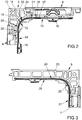
- FIG. 2 shows enlarged one of the corner 4 deflections FIG. 1
- the corner drive 4 has a deflecting element 11 arranged in a guide housing 10.
- the deflecting element 11 has a curved section 12 and two straight sections 13, 14 adjoining it. At the ends of the straight sections 13 , 14 coupling elements 15, 16 are arranged.
- the coupling elements 15, 16 generate a positive connection with the adjacent functional elements 6.
- the coupling elements 15, 16 can be easily connected to a portion of the drive rod 9.
- To illustrate the corner 4 is shown in partial section.
- the deflecting element 11 has a spring housing 17 with a flexible spring strip 18 arranged therein.
- the spring strip 18 holds the coupling elements 15, 16.
- a fixing element 19 is arranged in the bent section 12 of the deflecting element 11.
- the guide housing 10 is made in one piece and consists of a base plate 34 and perpendicular thereto bordering and reinforcing ribs 33. It has a groove 20 for receiving the bent portion 12 of the deflecting element 11.
- the groove 20 has at its the straight sections 13, 14 facing Ends expansions 21, 22 and allows a tolerance compensation to the adjacent functional elements 6.
- the guide housing 10 is made of plastic, preferably by injection molding, and extends in this embodiment exclusively on the bent portion 12 of the deflecting 11th
- FIG. 3 shows enlarged one of the corner baffles 5 FIG. 1 with a guide housing 23 and a deflecting element 24.
- the corner drive 5 differs from that of FIG. 2 only in that the guide housing 23 is L-shaped and extends over a bent portion 25 of the deflecting element 24 and one of two straight sections 26, 27. Otherwise, the corner 5 is like the off FIG. 2 built up.
- FIG. 4 shows greatly enlarged a sectional view through a portion of the corner 4 from FIG. 2 in the region of the bent portion 12 of the deflecting element 11 with the fixing element 19.
- the fixing element 19 has a guide 28 in the guide housing 10.
- the spring housing 17 also has a collar 29 for guiding the fixing element 19.
- the fixing element 19 has a conical projection 31 penetrating into a recess 30 of the spring band 18.
- the fixing element 19 holds the spring band 18 during assembly of the espagnolette fitting 3 in a designated position.
- the spring band 18 is displaced and the fixing element 19 is pressed out of the recess 30 in the spring band 18. Subsequently, the spring band 18 can move freely.
- FIG. 5 shows the corner 4 from FIG. 2 with a further embodiment of the fixing element 32.
- the fixing element 32 is non-positively or cohesively held on the surface of the spring band 18. During the initial actuation of the drive rod fitting 3, the frictional connection or the material connection is released and the spring band 18 can then be moved freely.
Landscapes
- Connection Of Plates (AREA)
- Casings For Electric Apparatus (AREA)
- Operating, Guiding And Securing Of Roll- Type Closing Members (AREA)
- Joining Of Corner Units Of Frames Or Wings (AREA)
Abstract
Description
- Die Erfindung betrifft eine Eckumlenkung für einen Treibstangenbeschlag eines gegen einen Rahmen schwenkbaren Flügels eines Fensters, einer Fenstertür oder dergleichen mit einem Umlenkelement, mit einem gebogenen Abschnitt und mit sich an den gebogenen Abschnitt anschließenden geraden Abschnitten des Umlenkelementes.
- Eine solche Eckumlenkung ist beispielsweise aus der
EP 2 199 505 A2 bekannt. Bei dieser Eckumlenkung erstreckt sich eine Führung für das Umlenkelement über zwei Schenkel. Das Umlenkelement hat Koppelelemente mit Formschlussflächen zur Verbindung mit angrenzenden Treibstangenabschnitten. Das Umlenkelement weist einen schwenkbaren Arm auf, welcher von einem Schieber derart verschwenkt werden kann, dass die Formschlussflächen des Umlenkelementes in Formschlussflächen des angrenzenden Treibstangenabschnitts gedrückt werden. Hierdurch ist eine teilweise verdeckte Anordnung des Ecklagers in dem Flügel möglich. Nachteilig bei diesem Ecklager ist jedoch, dass es eine große Tasche im Flügel erfordert. - Aus der
EP 2 142 737 B1 ist eine Eckumlenkung mit zwei Schenkeln bekannt geworden. Die Schenkel weisen jeweils eine Linearführung mit einem in der Linearführung geführten Schlitten auf. Die Schlitten sind über ein Umlenkmittel miteinander gekoppelt. Nachteilig bei der Eckumlenkung ist, dass es für die beiden Schenkel eine sehr große Tasche im Flügel benötigt, welche von außen zugänglich sein muss. - Der Erfindung liegt das Problem zugrunde, eine Eckumlenkung der eingangs genannten Art so weiter zu bilden, dass sie möglichst kleine Abmessungen aufweist und einfach aufgebaut ist.
- Dieses Problem wird erfindungsgemäß dadurch gelöst, dass das Umlenkelement in einem Führungsgehäuse angeordnet ist und dass das Führungsgehäuse das Umlenkelement an dem gebogenen Abschnitt hält.
- Durch diese Gestaltung lässt sich das Führungsgehäuse besonders klein gestalten. Daher kann die erfindungsgemäße Eckumlenkung auch in einer möglichst klein bemessenen Tasche im Flügel angeordnet werden. Da das Führungsgehäuse die Eckumlenkung an dem gebogenen Abschnitt hält, können die geraden Abschnitte des Umlenkelementes einfach aus dem Führungsgehäuse herausragen. Die Enden der geraden Abschnitte werden vorzugsweise von angrenzenden Funktionselementen des Treibstangenbeschlages geführt.
- Die Eckumlenkung weist gemäß einer anderen vorteilhaften Weiterbildung der Erfindung besonders kleine Abmessungen auf, wenn sich das Führungsgehäuse an zumindest einer Seite ausschließlich über den gebogenen Abschnitt des Umlenkelementes erstreckt. Damit ragt an dieser Seite der gerade Abschnitt des Umlenkelementes aus dem Führungsgehäuse heraus. Durch diese Gestaltung kann an dieser Seite unmittelbar angrenzend an den gebogenen Abschnitt ein weiteres Funktionselement, wie beispielsweise ein Verschluss angeordnet werden. Alternativ dazu kann eine Tasche im Flügel zur Aufnahme des Führungsgehäuses besonders klein gehalten werden.
- Die Eckumlenkung lässt sich gemäß einer anderen vorteilhaften Weiterbildung der Erfindung besonders kostengünstig fertigen, wenn das Führungsgehäuse eine Nut zur Aufnahme eines Teilbereichs des Umlenkelementes hat.
- Die Montage der Eckumlenkung gestaltet sich gemäß einer anderen vorteilhaften Weiterbildung der Erfindung besonders einfach, wenn die Nut quer zu ihrer längsten Erstreckung zu einer Seite des Führungsgehäuses hin offen ist. Weiterhin lässt sich das Umlenkelement durch diese Gestaltung einfach quer zu seiner längsten Erstreckung in die Nut eindrücken und gegebenenfalls verrasten. Damit gestaltet sich zudem die Montage der Eckumlenkung besonders einfach.
- Die Eckumlenkung ermöglicht gemäß einer anderen vorteilhaften Weiterbildung der Erfindung einen Ausgleich von Winkelabweichungen der geraden Abschnitte, wenn die Nut an zumindest einer Begrenzung des Führungsgehäuses Erweiterungen aufweist.
- Die Eckumlenkung ist besonders leicht und stabil ausgeführt, wenn das Führungsgehäuse einstückig ausgeführt ist und aus einer Grundplatte und darauf senkrecht aufgesetzten Begrenzung- und Verstärkungsrippen besteht. Die Begrenzung- und Verstärkungsrippen sind dabei idealerweise zumindest teilweise miteinander verbunden, um eine hohe Gesamtsteifigkeit zu erreichen. Bei dieser Ausführungsform haben die aufgesetzten Begrenzung- und Verstärkungsrippen jeweils ein der Grundplatte abgewandtes freies Ende, so dass sichtbare Kammern entstehen. Auch die offene Nut zur Aufnahme eines Teilbereichs des Umlenkelementes ist hierdurch gut realisierbar.
Das Führungsgehäuse kann somit einfach einstückig, z.B. aus Kunststoff hergestellt werden. Dieser Aufbau des Führungsgehäuses ist möglich, da die der Grundplatte gegenüberliegende Seite nach der Montage der Eckumlenkung in den Flügel zumindest weitgehend unsichtbar ist und daher keine besonderen Anforderungen an die optische Ausgestaltung stellt. - Die Eckumlenkung ermöglicht gemäß einer anderen vorteilhaften Weiterbildung der Erfindung eine sehr nahe Anordnung von Funktionselementen in Eckbereichen des Flügels, wenn zumindest einer der geraden Abschnitte in einem Funktionselement, insbesondere einem Funktionselement eines Verschlusses, des Treibstangenbeschlages angeordnet ist. Damit wird das Funktionselement Teil der Eckumlenkung.
- Die Eckumlenkung gestaltet sich gemäß einer anderen vorteilhaften Weiterbildung der Erfindung konstruktiv besonders einfach, wenn das Umlenkelement zumindest ein biegsames Federband und ein Federgehäuse zur Führung des zumindest einen Federbandes hat.
- Eine so genannte Mittenfixierung der Eckumlenkung lässt sich gemäß einer anderen vorteilhaften Weiterbildung der Erfindung einfach erzeugen, wenn das Federband von einem Fixierelement mit einem vorgesehenen Kraftaufwand in einer vorgesehenen Montagelage gehalten ist. Durch diese Gestaltung ist die von dem Fixierelement auf das Federband ausgeübte Haltekraft begrenzt, so dass die Halterung des Federbandes bei der Erstbetätigung des Treibstangenbeschlages lösbar ist.
- Die Eckumlenkung gestaltet sich gemäß einer anderen vorteilhaften Weiterbildung der Erfindung besonders kompakt, wenn das Fixierelement eine Führung in dem Führungsgehäuse hat. Da sich das Führungsgehäuse im Wesentlichen über den gebogenen Abschnitt des Umlenkelementes erstreckt, ist an dieser Stelle eine besonders große Materialstärke für die Erzeugung der Führung für das Fixierelement vorhanden.
- Eine Zerstörung des Fixierelementes bei der Erstbetätigung des Treibstangenbeschlages lässt sich gemäß einer anderen vorteilhaften Weiterbildung der Erfindung vermeiden, wenn das Fixierelement kraftschlüssig oder stoffschlüssig an dem Federband gehalten ist. Durch diese Gestaltung wird bei der Erstbetätigung des Treibstangenbeschlages der Kraftschluss oder der Stoffschluss mit dem Federband aufgehoben. Der Stoffschluss kann beispielsweise mittels Klebstoff erzeugt werden.
- Die Kraft zur Lösung der Verbindung des Fixierelementes mit dem Federband lässt sich gemäß einer anderen vorteilhaften Weiterbildung der Erfindung besonders genau begrenzen, wenn das Fixierelement einen in eine Ausnehmung des Federbandes eindringenden Vorsprung hat. Der Vorsprung kann beispielsweise Scherstift ausgebildet sein und bei dem vorgesehenen Kraftaufwand abscheren oder als Kegelstumpf ausgebildet sein und von dem vorgesehenen Kraftaufwand aus dem Bewegungsbereich des Federbandes heraus geschoben werden.
- Die Erfindung lässt zahlreiche Ausführungsformen zu. Zur weiteren Verdeutlichung ihres Grundprinzips sind mehrere davon in der Zeichnung dargestellt und werden nachfolgend beschrieben. Diese zeigt in
- Fig.1
- schematisch ein Fenster mit einem Treibstangenbeschlag mit mehreren Eckumlenkungen,
- Fig. 2
- vergrößert eine erste Ausführungsform der Eckumlenkung aus
Figur 1 , - Fig. 3
- vergrößert eine zweite Ausführungsform der Eckumlenkung aus
Figur 1 , - Fig. 4
- stark vergrößert eine Schnittdarstellung durch die Eckumlenkung mit einem Fixierelement,
- Fig. 5
- stark vergrößert die Eckumlenkung mit einer weiteren Ausführungsform eines Fixierelementes.
-
Figur 1 zeigt ein Fenster mit einem gegen einen Rahmen 1 schwenkbaren Flügel 2 und mit einem schematisch dargestellten Treibstangenbeschlag 3 zur Verriegelung des Flügels 2 in dem Rahmen 1. Der Treibstangenbeschlag 3 hat mehrere Eckumlenkungen 4, 5 und mehrere Funktionselemente 6, 7. Die Funktionselemente 6, 7 sind beispielsweise als Verschlüsse oder als Lagerteil einer Scherenlagerung ausgebildet. Der Treibstangenbeschlag 3 hat zudem ein Kantengetriebe 8 zum Antrieb einer Treibstange 9, welche mit den Funktionselementen 6, 7 oder den Eckumlenkungen 6, 7 verbunden ist. -
Figur 2 zeigt vergrößert eine der Eckumlenkungen 4 ausFigur 1 mit zwei angrenzenden, jeweils als Verschluss ausgebildeten Funktionselementen 6. Die Eckumlenkung 4 hat ein in einem Führungsgehäuse 10 angeordnetes Umlenkelement 11. Das Umlenkelement 11 hat einen gebogenen Abschnitt 12 und zwei sich daran anschließende gerade Abschnitte 13, 14. An den Enden der geraden Abschnitte 13, 14 sind Koppelelemente 15, 16 angeordnet. Die Koppelelemente 15, 16 erzeugen eine formschlüssige Verbindung mit den angrenzenden Funktionselementen 6. In einer nicht dargestellten Ausführungsform können die Koppelelemente 15, 16 einfach mit einem Abschnitt der Treibstange 9 verbunden sein. Zur Verdeutlichung ist die Eckumlenkung 4 im Teilschnitt dargestellt. Das Umlenkelement 11 hat ein Federgehäuse 17 mit einem darin angeordneten biegsamen Federband 18. Das Federband 18 haltert die Koppelelemente 15, 16. Im gebogenen Abschnitt 12 des Umlenkelementes 11 ist ein Fixierelement 19 angeordnet.
Das Führungsgehäuse 10 ist einstückig ausgeführt und besteht aus einer Grundplatte 34 und darauf senkrecht aufgesetzten Begrenzung- und Verstärkungsrippen 33. Es hat eine Nut 20 zur Aufnahme des gebogenen Abschnitts 12 des Umlenkelementes 11. Die Nut 20 weist an ihren den geraden Abschnitten 13, 14 zugewandten Enden Erweiterungen 21, 22 auf und ermöglicht einen Toleranzausgleich zu den angrenzenden Funktionselementen 6. Das Führungsgehäuse 10 ist aus Kunststoff, vorzugsweise im Spritzgussverfahren, gefertigt und erstreckt sich in dieser Ausführungsform ausschließlich über den gebogenen Abschnitt 12 des Umlenkelementes 11. -
Figur 3 zeigt vergrößert eine der Eckumlenkungen 5 ausFigur 1 mit einem Führungsgehäuse 23 und einem Umlenkelement 24. Die Eckumlenkung 5 unterscheidet sich von der ausFigur 2 nur dadurch, dass das Führungsgehäuse 23 L-förmig gestaltet ist und sich über einen gebogenen Abschnitt 25 des Umlenkelementes 24 und über einen von zwei geraden Abschnitten 26, 27 erstreckt. Ansonsten ist die Eckumlenkung 5 wie die ausFigur 2 aufgebaut. -
Figur 4 zeigt stark vergrößert eine Schnittdarstellung durch einen Teilbereich der Eckumlenkung 4 ausFigur 2 im Bereich des gebogenen Abschnitts 12 des Umlenkelements 11 mit dem Fixierelement 19. Hierbei ist zu erkennen, dass das Fixierelement 19 eine Führung 28 in dem Führungsgehäuse 10 hat. Das Federgehäuse 17 hat ebenfalls einen Kragen 29 zur Führung des Fixierelementes 19. Das Fixierelement 19 hat einen in eine Ausnehmung 30 des Federbandes 18 eindringenden kegelförmigen Vorsprung 31. Das Fixierelement 19 hält das Federband 18 während der Montage des Treibstangenbeschlages 3 in einer vorgesehenen Lage. Bei der Erstbetätigung des Treibstangenbeschlages 3 wird das Federband 18 verschoben und das Fixierelement 19 aus der Ausnehmung 30 im Federband 18 heraus gedrückt. Anschließend lässt sich das Federband 18 frei bewegen. -
Figur 5 zeigt die Eckumlenkung 4 ausFigur 2 mit einer weiteren Ausführungsform des Fixierelementes 32. Das Fixierelement 32 ist kraftschlüssig oder stoffschlüssig an der Oberfläche des Federbandes 18 gehalten. Bei der Erstbetätigung des Treibstangenbeschlages 3 wird der Kraftschluss oder der Stoffschluss gelöst und das Federband 18 lässt sich anschließend frei bewegen.
Claims (12)
- Eckumlenkung (4, 5) für einen Treibstangenbeschlag (3) eines gegen einen Rahmen (1) schwenkbaren Flügels (2) eines Fensters, einer Fenstertür oder dergleichen mit einem Umlenkelement (11, 24), mit einem gebogenen Abschnitt (12, 25) und mit sich an den gebogenen Abschnitt (12, 25) anschließenden geraden Abschnitten (13, 14, 26, 27) des Umlenkelementes (11, 24), dadurch gekennzeichnet, dass das Umlenkelement (11, 24) in einem Führungsgehäuse (10, 23) angeordnet ist und dass das Führungsgehäuse (10, 23) das Umlenkelement (11, 24) an dem gebogenen Abschnitt (12, 25) hält.
- Eckumlenkung nach Anspruch 1, dadurch gekennzeichnet, dass sich das Führungsgehäuse (10, 23) an zumindest einer Seite ausschließlich über den gebogenen Abschnitt (12, 25) des Umlenkelementes (11, 24) erstreckt.
- Eckumlenkung nach Anspruch 1 oder 2, dadurch gekennzeichnet, dass das Führungsgehäuse (10, 23) eine Nut (20) zur Aufnahme eines Teilbereichs des Umlenkelementes (11, 24) hat.
- Eckumlenkung nach Anspruch 3, dadurch gekennzeichnet, dass die Nut (20) quer zu ihrer längsten Erstreckung zu einer Seite des Führungsgehäuses (10, 23) hin offen ist.
- Eckumlenkung nach Anspruch 3 oder 4, dadurch gekennzeichnet, dass die Nut (20) an zumindest einer Begrenzung des Führungsgehäuses (10, 23) Erweiterungen (21, 22) aufweist.
- Eckumlenkung nach einem der vorhergehenden Ansprüche, dadurch gekennzeichnet, dass das Führungsgehäuse (10, 23) einstückig ausgeführt ist und aus einer Grundplatte (34) und darauf senkrecht aufgesetzten Begrenzung- und Verstärkungsrippen (33) besteht.
- Eckumlenkung nach einem der vorhergehenden Ansprüche, dadurch gekennzeichnet, dass zumindest einer der geraden Abschnitte (15, 16, 27) in einem Funktionselement (6, 7), insbesondere einem Funktionselement (6, 7) eines Verschlusses, des Treibstangenbeschlages (3) angeordnet ist.
- Eckumlenkung nach einem der vorhergehenden Ansprüche, dadurch gekennzeichnet, dass das Umlenkelement (11, 24) zumindest ein biegsames Federband (18) und ein Federgehäuse (17) zur Führung des zumindest einen Federbandes (18) hat.
- Eckumlenkung nach Anspruch 8, dadurch gekennzeichnet, dass das Federband (18) von einem Fixierelement (19, 32) mit einem vorgesehenen Kraftaufwand in einer vorgesehenen Montagelage gehalten ist.
- Eckumlenkung nach Anspruch 8 oder 9, dadurch gekennzeichnet, dass das Fixierelement (19, 32) eine Führung in dem Führungsgehäuse hat.
- Eckumlenkung nach einem der Ansprüche 8 bis 10, dadurch gekennzeichnet, dass das Fixierelement (32) kraftschlüssig oder stoffschlüssig an dem Federband (18) gehalten ist.
- Eckumlenkung nach einem der Ansprüche 8 bis 10, dadurch gekennzeichnet, dass das Fixierelement (19) einen in eine Ausnehmung (30) des Federbandes (18) eindringenden Vorsprung (31) hat.
Applications Claiming Priority (1)
| Application Number | Priority Date | Filing Date | Title |
|---|---|---|---|
| DE102017201250.1A DE102017201250A1 (de) | 2017-01-26 | 2017-01-26 | Eckumlenkung für einen Treibstangenbeschlag |
Publications (2)
| Publication Number | Publication Date |
|---|---|
| EP3354833A1 true EP3354833A1 (de) | 2018-08-01 |
| EP3354833B1 EP3354833B1 (de) | 2020-04-22 |
Family
ID=60953713
Family Applications (1)
| Application Number | Title | Priority Date | Filing Date |
|---|---|---|---|
| EP18150798.9A Active EP3354833B1 (de) | 2017-01-26 | 2018-01-09 | Eckumlenckung für einen treibstangenbeschlag |
Country Status (3)
| Country | Link |
|---|---|
| EP (1) | EP3354833B1 (de) |
| DE (1) | DE102017201250A1 (de) |
| ES (1) | ES2795060T3 (de) |
Families Citing this family (1)
| Publication number | Priority date | Publication date | Assignee | Title |
|---|---|---|---|---|
| DE102021203760B3 (de) | 2021-04-15 | 2022-04-07 | Roto Frank Fenster- und Türtechnologie GmbH | Beschlag mit einem durch Längsschieben arretierbaren Rasthaken |
Citations (6)
| Publication number | Priority date | Publication date | Assignee | Title |
|---|---|---|---|---|
| FR2275626A1 (fr) * | 1974-05-30 | 1976-01-16 | Winkhaus Fa August | Fenetre |
| DE2601390A1 (de) * | 1976-01-15 | 1977-07-21 | Hautau Baubeschlag | Eckumlenkung fuer treibstangenbeschlaege von fenstern, tueren o.dgl. |
| EP1022418A1 (de) * | 1999-01-22 | 2000-07-26 | Siegenia-Frank Kg | Eckumlenkung |
| DE19957358A1 (de) * | 1999-11-29 | 2001-06-07 | Veka Ag | Verfahren zum Bestücken eines Fensterrahmens mit einem Treibstangenbeschlagsystem und dazu geeignete Teile |
| EP2199505A2 (de) | 2008-12-15 | 2010-06-23 | Aug. Winkhaus GmbH & Co. KG | Kupplung zur Anbindung einer ein über zwei Schenkel geführtes Federband aufweisenden Eckumlenkung an einem längsverschieblichen Treibstangenabschnitt |
| EP2142737B1 (de) | 2007-04-02 | 2012-05-16 | Roto Frank Ag | Kraftübertragungsanordnung für ein fenster, eine tür oder dergleichen |
-
2017
- 2017-01-26 DE DE102017201250.1A patent/DE102017201250A1/de not_active Withdrawn
-
2018
- 2018-01-09 ES ES18150798T patent/ES2795060T3/es active Active
- 2018-01-09 EP EP18150798.9A patent/EP3354833B1/de active Active
Patent Citations (6)
| Publication number | Priority date | Publication date | Assignee | Title |
|---|---|---|---|---|
| FR2275626A1 (fr) * | 1974-05-30 | 1976-01-16 | Winkhaus Fa August | Fenetre |
| DE2601390A1 (de) * | 1976-01-15 | 1977-07-21 | Hautau Baubeschlag | Eckumlenkung fuer treibstangenbeschlaege von fenstern, tueren o.dgl. |
| EP1022418A1 (de) * | 1999-01-22 | 2000-07-26 | Siegenia-Frank Kg | Eckumlenkung |
| DE19957358A1 (de) * | 1999-11-29 | 2001-06-07 | Veka Ag | Verfahren zum Bestücken eines Fensterrahmens mit einem Treibstangenbeschlagsystem und dazu geeignete Teile |
| EP2142737B1 (de) | 2007-04-02 | 2012-05-16 | Roto Frank Ag | Kraftübertragungsanordnung für ein fenster, eine tür oder dergleichen |
| EP2199505A2 (de) | 2008-12-15 | 2010-06-23 | Aug. Winkhaus GmbH & Co. KG | Kupplung zur Anbindung einer ein über zwei Schenkel geführtes Federband aufweisenden Eckumlenkung an einem längsverschieblichen Treibstangenabschnitt |
Also Published As
| Publication number | Publication date |
|---|---|
| EP3354833B1 (de) | 2020-04-22 |
| ES2795060T3 (es) | 2020-11-20 |
| DE102017201250A1 (de) | 2018-07-26 |
Similar Documents
| Publication | Publication Date | Title |
|---|---|---|
| DE102006010755A1 (de) | Verstellvorrichtung für einen Schiebedachdeckel an einem Fahrzeug | |
| EP3354833B1 (de) | Eckumlenckung für einen treibstangenbeschlag | |
| DE102018111201A1 (de) | Beschlaganordnung für ein Schiebefenster oder eine Schiebetür | |
| EP3094803B1 (de) | Schiebetüranordnung mit in einer gemeinsamen ebene angeordneten schiebeflügeln | |
| DE102019209860A1 (de) | SCHLIEßBLECH FÜR EINEN TREIBSTANGENBESCHLAG | |
| EP0808974A2 (de) | Schnappriegelvorrichtung für Flügel von Fenstern, Türen oder dgl. | |
| DE102012213786B3 (de) | Verlagerungsanordnung zur Verlagerung eines Flügels eines Fensters, einer Tür oder dergleichen relativ zu einer festen Einfassung | |
| DE102012001644B4 (de) | Fensterführungsvorrichtung | |
| DE3248053A1 (de) | Loesbare, auf unterschiedliche tuerdicken einstellbare dornbefestigung fuer tuerhandhaben | |
| DE102004060717B4 (de) | Verschluss zur Verriegelung eines Flügels in einem Rahmen eines Fensters | |
| EP1798360B1 (de) | Beschlagteil für einen Treibstangenbeschlag | |
| DE2010407A1 (de) | Eckumlenkung zum Verbinden der Treib stangen von Fenster und Turbeschlagen | |
| EP1905930B1 (de) | Schnäpper für Balkon- oder Terrassentüren | |
| DE202022107184U1 (de) | Aufhängesystem zum Aufhängen einer Gardine | |
| EP2444574A2 (de) | Halteelement eines Beschlagteils eines Treibstangenbeschlages | |
| EP3495592A1 (de) | Bremseinrichtung für einen gegenüber einem feststehenden rahmen bewegbaren flügel | |
| EP1918496B1 (de) | Treibstangenbeschlag für einen gegen einen Rahmen schwenkbaren Flügel eines Fensters | |
| DE202017106969U1 (de) | Eine Scharnieranordnung mit einer Bremseinrichtung und einer Vorspanneinrichtung, sowie ein Dachfenster mit einer derartigen Scharnieranordnung | |
| DE102009027525A1 (de) | Eckumlenkung für einen Treibstangenbeschlag | |
| EP3088639A1 (de) | Vorrichtung zum ausrichten von einander gegenüberstehend anzuordnenden beschlagteilen | |
| DE9113676U1 (de) | Tastschalter mit Ansatz | |
| DE10245063A1 (de) | Fahrzeugdach mit einer Randspaltdichtung zur Abdichtung eines Deckels und mit einem Windabweiser an einem Dachöffnungsrand | |
| EP1867818B1 (de) | Verschluss für einen Treibstangenbeschlag und Fenster, Fenstertür oder dergleichen mit einem solchen Verschluss | |
| DE202013101886U1 (de) | Schließvorrichtung, insbesondere Schließvorrichtung für eine Tür oder ein Fenster | |
| DE202004020685U1 (de) | Türschließer |
Legal Events
| Date | Code | Title | Description |
|---|---|---|---|
| PUAI | Public reference made under article 153(3) epc to a published international application that has entered the european phase |
Free format text: ORIGINAL CODE: 0009012 |
|
| STAA | Information on the status of an ep patent application or granted ep patent |
Free format text: STATUS: THE APPLICATION HAS BEEN PUBLISHED |
|
| AK | Designated contracting states |
Kind code of ref document: A1 Designated state(s): AL AT BE BG CH CY CZ DE DK EE ES FI FR GB GR HR HU IE IS IT LI LT LU LV MC MK MT NL NO PL PT RO RS SE SI SK SM TR |
|
| AX | Request for extension of the european patent |
Extension state: BA ME |
|
| STAA | Information on the status of an ep patent application or granted ep patent |
Free format text: STATUS: REQUEST FOR EXAMINATION WAS MADE |
|
| 17P | Request for examination filed |
Effective date: 20190107 |
|
| RBV | Designated contracting states (corrected) |
Designated state(s): AL AT BE BG CH CY CZ DE DK EE ES FI FR GB GR HR HU IE IS IT LI LT LU LV MC MK MT NL NO PL PT RO RS SE SI SK SM TR |
|
| STAA | Information on the status of an ep patent application or granted ep patent |
Free format text: STATUS: EXAMINATION IS IN PROGRESS |
|
| 17Q | First examination report despatched |
Effective date: 20190502 |
|
| GRAP | Despatch of communication of intention to grant a patent |
Free format text: ORIGINAL CODE: EPIDOSNIGR1 |
|
| STAA | Information on the status of an ep patent application or granted ep patent |
Free format text: STATUS: GRANT OF PATENT IS INTENDED |
|
| INTG | Intention to grant announced |
Effective date: 20191209 |
|
| GRAS | Grant fee paid |
Free format text: ORIGINAL CODE: EPIDOSNIGR3 |
|
| GRAA | (expected) grant |
Free format text: ORIGINAL CODE: 0009210 |
|
| STAA | Information on the status of an ep patent application or granted ep patent |
Free format text: STATUS: THE PATENT HAS BEEN GRANTED |
|
| AK | Designated contracting states |
Kind code of ref document: B1 Designated state(s): AL AT BE BG CH CY CZ DE DK EE ES FI FR GB GR HR HU IE IS IT LI LT LU LV MC MK MT NL NO PL PT RO RS SE SI SK SM TR |
|
| REG | Reference to a national code |
Ref country code: CH Ref legal event code: EP |
|
| REG | Reference to a national code |
Ref country code: IE Ref legal event code: FG4D Free format text: LANGUAGE OF EP DOCUMENT: GERMAN |
|
| REG | Reference to a national code |
Ref country code: DE Ref legal event code: R096 Ref document number: 502018001224 Country of ref document: DE |
|
| REG | Reference to a national code |
Ref country code: AT Ref legal event code: REF Ref document number: 1260273 Country of ref document: AT Kind code of ref document: T Effective date: 20200515 |
|
| REG | Reference to a national code |
Ref country code: LT Ref legal event code: MG4D |
|
| REG | Reference to a national code |
Ref country code: NL Ref legal event code: MP Effective date: 20200422 |
|
| PG25 | Lapsed in a contracting state [announced via postgrant information from national office to epo] |
Ref country code: FI Free format text: LAPSE BECAUSE OF FAILURE TO SUBMIT A TRANSLATION OF THE DESCRIPTION OR TO PAY THE FEE WITHIN THE PRESCRIBED TIME-LIMIT Effective date: 20200422 Ref country code: PT Free format text: LAPSE BECAUSE OF FAILURE TO SUBMIT A TRANSLATION OF THE DESCRIPTION OR TO PAY THE FEE WITHIN THE PRESCRIBED TIME-LIMIT Effective date: 20200824 Ref country code: NL Free format text: LAPSE BECAUSE OF FAILURE TO SUBMIT A TRANSLATION OF THE DESCRIPTION OR TO PAY THE FEE WITHIN THE PRESCRIBED TIME-LIMIT Effective date: 20200422 Ref country code: SE Free format text: LAPSE BECAUSE OF FAILURE TO SUBMIT A TRANSLATION OF THE DESCRIPTION OR TO PAY THE FEE WITHIN THE PRESCRIBED TIME-LIMIT Effective date: 20200422 Ref country code: LT Free format text: LAPSE BECAUSE OF FAILURE TO SUBMIT A TRANSLATION OF THE DESCRIPTION OR TO PAY THE FEE WITHIN THE PRESCRIBED TIME-LIMIT Effective date: 20200422 Ref country code: GR Free format text: LAPSE BECAUSE OF FAILURE TO SUBMIT A TRANSLATION OF THE DESCRIPTION OR TO PAY THE FEE WITHIN THE PRESCRIBED TIME-LIMIT Effective date: 20200723 Ref country code: NO Free format text: LAPSE BECAUSE OF FAILURE TO SUBMIT A TRANSLATION OF THE DESCRIPTION OR TO PAY THE FEE WITHIN THE PRESCRIBED TIME-LIMIT Effective date: 20200722 Ref country code: IS Free format text: LAPSE BECAUSE OF FAILURE TO SUBMIT A TRANSLATION OF THE DESCRIPTION OR TO PAY THE FEE WITHIN THE PRESCRIBED TIME-LIMIT Effective date: 20200822 |
|
| REG | Reference to a national code |
Ref country code: ES Ref legal event code: FG2A Ref document number: 2795060 Country of ref document: ES Kind code of ref document: T3 Effective date: 20201120 |
|
| PG25 | Lapsed in a contracting state [announced via postgrant information from national office to epo] |
Ref country code: BG Free format text: LAPSE BECAUSE OF FAILURE TO SUBMIT A TRANSLATION OF THE DESCRIPTION OR TO PAY THE FEE WITHIN THE PRESCRIBED TIME-LIMIT Effective date: 20200722 Ref country code: RS Free format text: LAPSE BECAUSE OF FAILURE TO SUBMIT A TRANSLATION OF THE DESCRIPTION OR TO PAY THE FEE WITHIN THE PRESCRIBED TIME-LIMIT Effective date: 20200422 Ref country code: LV Free format text: LAPSE BECAUSE OF FAILURE TO SUBMIT A TRANSLATION OF THE DESCRIPTION OR TO PAY THE FEE WITHIN THE PRESCRIBED TIME-LIMIT Effective date: 20200422 Ref country code: HR Free format text: LAPSE BECAUSE OF FAILURE TO SUBMIT A TRANSLATION OF THE DESCRIPTION OR TO PAY THE FEE WITHIN THE PRESCRIBED TIME-LIMIT Effective date: 20200422 |
|
| PG25 | Lapsed in a contracting state [announced via postgrant information from national office to epo] |
Ref country code: AL Free format text: LAPSE BECAUSE OF FAILURE TO SUBMIT A TRANSLATION OF THE DESCRIPTION OR TO PAY THE FEE WITHIN THE PRESCRIBED TIME-LIMIT Effective date: 20200422 |
|
| REG | Reference to a national code |
Ref country code: DE Ref legal event code: R097 Ref document number: 502018001224 Country of ref document: DE |
|
| PG25 | Lapsed in a contracting state [announced via postgrant information from national office to epo] |
Ref country code: DK Free format text: LAPSE BECAUSE OF FAILURE TO SUBMIT A TRANSLATION OF THE DESCRIPTION OR TO PAY THE FEE WITHIN THE PRESCRIBED TIME-LIMIT Effective date: 20200422 Ref country code: EE Free format text: LAPSE BECAUSE OF FAILURE TO SUBMIT A TRANSLATION OF THE DESCRIPTION OR TO PAY THE FEE WITHIN THE PRESCRIBED TIME-LIMIT Effective date: 20200422 Ref country code: SM Free format text: LAPSE BECAUSE OF FAILURE TO SUBMIT A TRANSLATION OF THE DESCRIPTION OR TO PAY THE FEE WITHIN THE PRESCRIBED TIME-LIMIT Effective date: 20200422 Ref country code: CZ Free format text: LAPSE BECAUSE OF FAILURE TO SUBMIT A TRANSLATION OF THE DESCRIPTION OR TO PAY THE FEE WITHIN THE PRESCRIBED TIME-LIMIT Effective date: 20200422 Ref country code: RO Free format text: LAPSE BECAUSE OF FAILURE TO SUBMIT A TRANSLATION OF THE DESCRIPTION OR TO PAY THE FEE WITHIN THE PRESCRIBED TIME-LIMIT Effective date: 20200422 |
|
| PG25 | Lapsed in a contracting state [announced via postgrant information from national office to epo] |
Ref country code: SK Free format text: LAPSE BECAUSE OF FAILURE TO SUBMIT A TRANSLATION OF THE DESCRIPTION OR TO PAY THE FEE WITHIN THE PRESCRIBED TIME-LIMIT Effective date: 20200422 Ref country code: PL Free format text: LAPSE BECAUSE OF FAILURE TO SUBMIT A TRANSLATION OF THE DESCRIPTION OR TO PAY THE FEE WITHIN THE PRESCRIBED TIME-LIMIT Effective date: 20200422 |
|
| PLBE | No opposition filed within time limit |
Free format text: ORIGINAL CODE: 0009261 |
|
| STAA | Information on the status of an ep patent application or granted ep patent |
Free format text: STATUS: NO OPPOSITION FILED WITHIN TIME LIMIT |
|
| 26N | No opposition filed |
Effective date: 20210125 |
|
| PG25 | Lapsed in a contracting state [announced via postgrant information from national office to epo] |
Ref country code: SI Free format text: LAPSE BECAUSE OF FAILURE TO SUBMIT A TRANSLATION OF THE DESCRIPTION OR TO PAY THE FEE WITHIN THE PRESCRIBED TIME-LIMIT Effective date: 20200422 |
|
| PG25 | Lapsed in a contracting state [announced via postgrant information from national office to epo] |
Ref country code: MC Free format text: LAPSE BECAUSE OF FAILURE TO SUBMIT A TRANSLATION OF THE DESCRIPTION OR TO PAY THE FEE WITHIN THE PRESCRIBED TIME-LIMIT Effective date: 20200422 |
|
| REG | Reference to a national code |
Ref country code: CH Ref legal event code: PL |
|
| PG25 | Lapsed in a contracting state [announced via postgrant information from national office to epo] |
Ref country code: LU Free format text: LAPSE BECAUSE OF NON-PAYMENT OF DUE FEES Effective date: 20210109 |
|
| PG25 | Lapsed in a contracting state [announced via postgrant information from national office to epo] |
Ref country code: CH Free format text: LAPSE BECAUSE OF NON-PAYMENT OF DUE FEES Effective date: 20210131 Ref country code: LI Free format text: LAPSE BECAUSE OF NON-PAYMENT OF DUE FEES Effective date: 20210131 |
|
| PG25 | Lapsed in a contracting state [announced via postgrant information from national office to epo] |
Ref country code: IE Free format text: LAPSE BECAUSE OF NON-PAYMENT OF DUE FEES Effective date: 20210109 |
|
| P01 | Opt-out of the competence of the unified patent court (upc) registered |
Effective date: 20230516 |
|
| PG25 | Lapsed in a contracting state [announced via postgrant information from national office to epo] |
Ref country code: CY Free format text: LAPSE BECAUSE OF FAILURE TO SUBMIT A TRANSLATION OF THE DESCRIPTION OR TO PAY THE FEE WITHIN THE PRESCRIBED TIME-LIMIT Effective date: 20200422 |
|
| PG25 | Lapsed in a contracting state [announced via postgrant information from national office to epo] |
Ref country code: HU Free format text: LAPSE BECAUSE OF FAILURE TO SUBMIT A TRANSLATION OF THE DESCRIPTION OR TO PAY THE FEE WITHIN THE PRESCRIBED TIME-LIMIT; INVALID AB INITIO Effective date: 20180109 |
|
| PG25 | Lapsed in a contracting state [announced via postgrant information from national office to epo] |
Ref country code: MK Free format text: LAPSE BECAUSE OF FAILURE TO SUBMIT A TRANSLATION OF THE DESCRIPTION OR TO PAY THE FEE WITHIN THE PRESCRIBED TIME-LIMIT Effective date: 20200422 |
|
| PG25 | Lapsed in a contracting state [announced via postgrant information from national office to epo] |
Ref country code: TR Free format text: LAPSE BECAUSE OF FAILURE TO SUBMIT A TRANSLATION OF THE DESCRIPTION OR TO PAY THE FEE WITHIN THE PRESCRIBED TIME-LIMIT Effective date: 20200422 |
|
| PG25 | Lapsed in a contracting state [announced via postgrant information from national office to epo] |
Ref country code: MT Free format text: LAPSE BECAUSE OF FAILURE TO SUBMIT A TRANSLATION OF THE DESCRIPTION OR TO PAY THE FEE WITHIN THE PRESCRIBED TIME-LIMIT Effective date: 20200422 |
|
| REG | Reference to a national code |
Ref country code: DE Ref legal event code: R081 Ref document number: 502018001224 Country of ref document: DE Owner name: AUG. WINKHAUS SE & CO. KG, DE Free format text: FORMER OWNER: AUG. WINKHAUS GMBH & CO. KG, 48291 TELGTE, DE Ref country code: DE Ref legal event code: R081 Ref document number: 502018001224 Country of ref document: DE Owner name: AUG. WINKHAUS SE, DE Free format text: FORMER OWNER: AUG. WINKHAUS GMBH & CO. KG, 48291 TELGTE, DE |
|
| REG | Reference to a national code |
Ref country code: DE Ref legal event code: R081 Ref document number: 502018001224 Country of ref document: DE Owner name: AUG. WINKHAUS SE, DE Free format text: FORMER OWNER: AUG. WINKHAUS SE & CO. KG, 48291 TELGTE, DE |
|
| PGFP | Annual fee paid to national office [announced via postgrant information from national office to epo] |
Ref country code: GB Payment date: 20260122 Year of fee payment: 9 |
|
| PGFP | Annual fee paid to national office [announced via postgrant information from national office to epo] |
Ref country code: ES Payment date: 20260217 Year of fee payment: 9 |
|
| PGFP | Annual fee paid to national office [announced via postgrant information from national office to epo] |
Ref country code: DE Payment date: 20260120 Year of fee payment: 9 |
|
| PGFP | Annual fee paid to national office [announced via postgrant information from national office to epo] |
Ref country code: AT Payment date: 20260119 Year of fee payment: 9 |
|
| PGFP | Annual fee paid to national office [announced via postgrant information from national office to epo] |
Ref country code: BE Payment date: 20260121 Year of fee payment: 9 Ref country code: IT Payment date: 20260130 Year of fee payment: 9 |
|
| PGFP | Annual fee paid to national office [announced via postgrant information from national office to epo] |
Ref country code: FR Payment date: 20260123 Year of fee payment: 9 |