EP3354511B1 - Driving circuit for electric vehicle and control method therefor - Google Patents
Driving circuit for electric vehicle and control method therefor Download PDFInfo
- Publication number
- EP3354511B1 EP3354511B1 EP17815599.0A EP17815599A EP3354511B1 EP 3354511 B1 EP3354511 B1 EP 3354511B1 EP 17815599 A EP17815599 A EP 17815599A EP 3354511 B1 EP3354511 B1 EP 3354511B1
- Authority
- EP
- European Patent Office
- Prior art keywords
- contactor
- control signal
- control unit
- electric vehicle
- resistor
- Prior art date
- Legal status (The legal status is an assumption and is not a legal conclusion. Google has not performed a legal analysis and makes no representation as to the accuracy of the status listed.)
- Active
Links
- 238000000034 method Methods 0.000 title claims description 15
- 239000003990 capacitor Substances 0.000 claims description 35
- 230000008439 repair process Effects 0.000 description 5
- 230000008901 benefit Effects 0.000 description 4
- 230000004044 response Effects 0.000 description 4
- WHXSMMKQMYFTQS-UHFFFAOYSA-N Lithium Chemical compound [Li] WHXSMMKQMYFTQS-UHFFFAOYSA-N 0.000 description 3
- 230000000694 effects Effects 0.000 description 3
- 230000006870 function Effects 0.000 description 3
- 229910052744 lithium Inorganic materials 0.000 description 3
- PXHVJJICTQNCMI-UHFFFAOYSA-N Nickel Chemical compound [Ni] PXHVJJICTQNCMI-UHFFFAOYSA-N 0.000 description 2
- 230000003247 decreasing effect Effects 0.000 description 2
- 238000010586 diagram Methods 0.000 description 2
- 230000008569 process Effects 0.000 description 2
- XUIMIQQOPSSXEZ-UHFFFAOYSA-N Silicon Chemical compound [Si] XUIMIQQOPSSXEZ-UHFFFAOYSA-N 0.000 description 1
- 230000002159 abnormal effect Effects 0.000 description 1
- 238000003491 array Methods 0.000 description 1
- 239000006227 byproduct Substances 0.000 description 1
- 238000004146 energy storage Methods 0.000 description 1
- 238000002474 experimental method Methods 0.000 description 1
- 239000002803 fossil fuel Substances 0.000 description 1
- 229910052739 hydrogen Inorganic materials 0.000 description 1
- 239000001257 hydrogen Substances 0.000 description 1
- 230000007257 malfunction Effects 0.000 description 1
- 238000005259 measurement Methods 0.000 description 1
- 230000003446 memory effect Effects 0.000 description 1
- 229910052759 nickel Inorganic materials 0.000 description 1
- QELJHCBNGDEXLD-UHFFFAOYSA-N nickel zinc Chemical compound [Ni].[Zn] QELJHCBNGDEXLD-UHFFFAOYSA-N 0.000 description 1
- 239000000047 product Substances 0.000 description 1
- 229910052710 silicon Inorganic materials 0.000 description 1
- 239000010703 silicon Substances 0.000 description 1
- 239000007787 solid Substances 0.000 description 1
- 230000003068 static effect Effects 0.000 description 1
Images

Classifications
-
- B—PERFORMING OPERATIONS; TRANSPORTING
- B60—VEHICLES IN GENERAL
- B60L—PROPULSION OF ELECTRICALLY-PROPELLED VEHICLES; SUPPLYING ELECTRIC POWER FOR AUXILIARY EQUIPMENT OF ELECTRICALLY-PROPELLED VEHICLES; ELECTRODYNAMIC BRAKE SYSTEMS FOR VEHICLES IN GENERAL; MAGNETIC SUSPENSION OR LEVITATION FOR VEHICLES; MONITORING OPERATING VARIABLES OF ELECTRICALLY-PROPELLED VEHICLES; ELECTRIC SAFETY DEVICES FOR ELECTRICALLY-PROPELLED VEHICLES
- B60L58/00—Methods or circuit arrangements for monitoring or controlling batteries or fuel cells, specially adapted for electric vehicles
- B60L58/10—Methods or circuit arrangements for monitoring or controlling batteries or fuel cells, specially adapted for electric vehicles for monitoring or controlling batteries
-
- B—PERFORMING OPERATIONS; TRANSPORTING
- B60—VEHICLES IN GENERAL
- B60L—PROPULSION OF ELECTRICALLY-PROPELLED VEHICLES; SUPPLYING ELECTRIC POWER FOR AUXILIARY EQUIPMENT OF ELECTRICALLY-PROPELLED VEHICLES; ELECTRODYNAMIC BRAKE SYSTEMS FOR VEHICLES IN GENERAL; MAGNETIC SUSPENSION OR LEVITATION FOR VEHICLES; MONITORING OPERATING VARIABLES OF ELECTRICALLY-PROPELLED VEHICLES; ELECTRIC SAFETY DEVICES FOR ELECTRICALLY-PROPELLED VEHICLES
- B60L3/00—Electric devices on electrically-propelled vehicles for safety purposes; Monitoring operating variables, e.g. speed, deceleration or energy consumption
- B60L3/0023—Detecting, eliminating, remedying or compensating for drive train abnormalities, e.g. failures within the drive train
- B60L3/0069—Detecting, eliminating, remedying or compensating for drive train abnormalities, e.g. failures within the drive train relating to the isolation, e.g. ground fault or leak current
-
- B—PERFORMING OPERATIONS; TRANSPORTING
- B60—VEHICLES IN GENERAL
- B60L—PROPULSION OF ELECTRICALLY-PROPELLED VEHICLES; SUPPLYING ELECTRIC POWER FOR AUXILIARY EQUIPMENT OF ELECTRICALLY-PROPELLED VEHICLES; ELECTRODYNAMIC BRAKE SYSTEMS FOR VEHICLES IN GENERAL; MAGNETIC SUSPENSION OR LEVITATION FOR VEHICLES; MONITORING OPERATING VARIABLES OF ELECTRICALLY-PROPELLED VEHICLES; ELECTRIC SAFETY DEVICES FOR ELECTRICALLY-PROPELLED VEHICLES
- B60L3/00—Electric devices on electrically-propelled vehicles for safety purposes; Monitoring operating variables, e.g. speed, deceleration or energy consumption
- B60L3/0092—Electric devices on electrically-propelled vehicles for safety purposes; Monitoring operating variables, e.g. speed, deceleration or energy consumption with use of redundant elements for safety purposes
-
- B—PERFORMING OPERATIONS; TRANSPORTING
- B60—VEHICLES IN GENERAL
- B60L—PROPULSION OF ELECTRICALLY-PROPELLED VEHICLES; SUPPLYING ELECTRIC POWER FOR AUXILIARY EQUIPMENT OF ELECTRICALLY-PROPELLED VEHICLES; ELECTRODYNAMIC BRAKE SYSTEMS FOR VEHICLES IN GENERAL; MAGNETIC SUSPENSION OR LEVITATION FOR VEHICLES; MONITORING OPERATING VARIABLES OF ELECTRICALLY-PROPELLED VEHICLES; ELECTRIC SAFETY DEVICES FOR ELECTRICALLY-PROPELLED VEHICLES
- B60L3/00—Electric devices on electrically-propelled vehicles for safety purposes; Monitoring operating variables, e.g. speed, deceleration or energy consumption
- B60L3/04—Cutting off the power supply under fault conditions
-
- B—PERFORMING OPERATIONS; TRANSPORTING
- B60—VEHICLES IN GENERAL
- B60L—PROPULSION OF ELECTRICALLY-PROPELLED VEHICLES; SUPPLYING ELECTRIC POWER FOR AUXILIARY EQUIPMENT OF ELECTRICALLY-PROPELLED VEHICLES; ELECTRODYNAMIC BRAKE SYSTEMS FOR VEHICLES IN GENERAL; MAGNETIC SUSPENSION OR LEVITATION FOR VEHICLES; MONITORING OPERATING VARIABLES OF ELECTRICALLY-PROPELLED VEHICLES; ELECTRIC SAFETY DEVICES FOR ELECTRICALLY-PROPELLED VEHICLES
- B60L3/00—Electric devices on electrically-propelled vehicles for safety purposes; Monitoring operating variables, e.g. speed, deceleration or energy consumption
- B60L3/06—Limiting the traction current under mechanical overload conditions
-
- B—PERFORMING OPERATIONS; TRANSPORTING
- B60—VEHICLES IN GENERAL
- B60L—PROPULSION OF ELECTRICALLY-PROPELLED VEHICLES; SUPPLYING ELECTRIC POWER FOR AUXILIARY EQUIPMENT OF ELECTRICALLY-PROPELLED VEHICLES; ELECTRODYNAMIC BRAKE SYSTEMS FOR VEHICLES IN GENERAL; MAGNETIC SUSPENSION OR LEVITATION FOR VEHICLES; MONITORING OPERATING VARIABLES OF ELECTRICALLY-PROPELLED VEHICLES; ELECTRIC SAFETY DEVICES FOR ELECTRICALLY-PROPELLED VEHICLES
- B60L50/00—Electric propulsion with power supplied within the vehicle
- B60L50/50—Electric propulsion with power supplied within the vehicle using propulsion power supplied by batteries or fuel cells
- B60L50/60—Electric propulsion with power supplied within the vehicle using propulsion power supplied by batteries or fuel cells using power supplied by batteries
-
- B—PERFORMING OPERATIONS; TRANSPORTING
- B60—VEHICLES IN GENERAL
- B60L—PROPULSION OF ELECTRICALLY-PROPELLED VEHICLES; SUPPLYING ELECTRIC POWER FOR AUXILIARY EQUIPMENT OF ELECTRICALLY-PROPELLED VEHICLES; ELECTRODYNAMIC BRAKE SYSTEMS FOR VEHICLES IN GENERAL; MAGNETIC SUSPENSION OR LEVITATION FOR VEHICLES; MONITORING OPERATING VARIABLES OF ELECTRICALLY-PROPELLED VEHICLES; ELECTRIC SAFETY DEVICES FOR ELECTRICALLY-PROPELLED VEHICLES
- B60L53/00—Methods of charging batteries, specially adapted for electric vehicles; Charging stations or on-board charging equipment therefor; Exchange of energy storage elements in electric vehicles
- B60L53/20—Methods of charging batteries, specially adapted for electric vehicles; Charging stations or on-board charging equipment therefor; Exchange of energy storage elements in electric vehicles characterised by converters located in the vehicle
-
- B—PERFORMING OPERATIONS; TRANSPORTING
- B60—VEHICLES IN GENERAL
- B60L—PROPULSION OF ELECTRICALLY-PROPELLED VEHICLES; SUPPLYING ELECTRIC POWER FOR AUXILIARY EQUIPMENT OF ELECTRICALLY-PROPELLED VEHICLES; ELECTRODYNAMIC BRAKE SYSTEMS FOR VEHICLES IN GENERAL; MAGNETIC SUSPENSION OR LEVITATION FOR VEHICLES; MONITORING OPERATING VARIABLES OF ELECTRICALLY-PROPELLED VEHICLES; ELECTRIC SAFETY DEVICES FOR ELECTRICALLY-PROPELLED VEHICLES
- B60L53/00—Methods of charging batteries, specially adapted for electric vehicles; Charging stations or on-board charging equipment therefor; Exchange of energy storage elements in electric vehicles
- B60L53/50—Charging stations characterised by energy-storage or power-generation means
- B60L53/53—Batteries
-
- B—PERFORMING OPERATIONS; TRANSPORTING
- B60—VEHICLES IN GENERAL
- B60L—PROPULSION OF ELECTRICALLY-PROPELLED VEHICLES; SUPPLYING ELECTRIC POWER FOR AUXILIARY EQUIPMENT OF ELECTRICALLY-PROPELLED VEHICLES; ELECTRODYNAMIC BRAKE SYSTEMS FOR VEHICLES IN GENERAL; MAGNETIC SUSPENSION OR LEVITATION FOR VEHICLES; MONITORING OPERATING VARIABLES OF ELECTRICALLY-PROPELLED VEHICLES; ELECTRIC SAFETY DEVICES FOR ELECTRICALLY-PROPELLED VEHICLES
- B60L53/00—Methods of charging batteries, specially adapted for electric vehicles; Charging stations or on-board charging equipment therefor; Exchange of energy storage elements in electric vehicles
- B60L53/50—Charging stations characterised by energy-storage or power-generation means
- B60L53/55—Capacitors
-
- B—PERFORMING OPERATIONS; TRANSPORTING
- B60—VEHICLES IN GENERAL
- B60L—PROPULSION OF ELECTRICALLY-PROPELLED VEHICLES; SUPPLYING ELECTRIC POWER FOR AUXILIARY EQUIPMENT OF ELECTRICALLY-PROPELLED VEHICLES; ELECTRODYNAMIC BRAKE SYSTEMS FOR VEHICLES IN GENERAL; MAGNETIC SUSPENSION OR LEVITATION FOR VEHICLES; MONITORING OPERATING VARIABLES OF ELECTRICALLY-PROPELLED VEHICLES; ELECTRIC SAFETY DEVICES FOR ELECTRICALLY-PROPELLED VEHICLES
- B60L58/00—Methods or circuit arrangements for monitoring or controlling batteries or fuel cells, specially adapted for electric vehicles
- B60L58/10—Methods or circuit arrangements for monitoring or controlling batteries or fuel cells, specially adapted for electric vehicles for monitoring or controlling batteries
- B60L58/18—Methods or circuit arrangements for monitoring or controlling batteries or fuel cells, specially adapted for electric vehicles for monitoring or controlling batteries of two or more battery modules
- B60L58/21—Methods or circuit arrangements for monitoring or controlling batteries or fuel cells, specially adapted for electric vehicles for monitoring or controlling batteries of two or more battery modules having the same nominal voltage
-
- G—PHYSICS
- G01—MEASURING; TESTING
- G01R—MEASURING ELECTRIC VARIABLES; MEASURING MAGNETIC VARIABLES
- G01R19/00—Arrangements for measuring currents or voltages or for indicating presence or sign thereof
- G01R19/165—Indicating that current or voltage is either above or below a predetermined value or within or outside a predetermined range of values
- G01R19/16533—Indicating that current or voltage is either above or below a predetermined value or within or outside a predetermined range of values characterised by the application
- G01R19/16538—Indicating that current or voltage is either above or below a predetermined value or within or outside a predetermined range of values characterised by the application in AC or DC supplies
- G01R19/16542—Indicating that current or voltage is either above or below a predetermined value or within or outside a predetermined range of values characterised by the application in AC or DC supplies for batteries
-
- G—PHYSICS
- G01—MEASURING; TESTING
- G01R—MEASURING ELECTRIC VARIABLES; MEASURING MAGNETIC VARIABLES
- G01R31/00—Arrangements for testing electric properties; Arrangements for locating electric faults; Arrangements for electrical testing characterised by what is being tested not provided for elsewhere
- G01R31/005—Testing of electric installations on transport means
- G01R31/006—Testing of electric installations on transport means on road vehicles, e.g. automobiles or trucks
-
- G—PHYSICS
- G01—MEASURING; TESTING
- G01R—MEASURING ELECTRIC VARIABLES; MEASURING MAGNETIC VARIABLES
- G01R31/00—Arrangements for testing electric properties; Arrangements for locating electric faults; Arrangements for electrical testing characterised by what is being tested not provided for elsewhere
- G01R31/36—Arrangements for testing, measuring or monitoring the electrical condition of accumulators or electric batteries, e.g. capacity or state of charge [SoC]
- G01R31/364—Battery terminal connectors with integrated measuring arrangements
-
- H—ELECTRICITY
- H01—ELECTRIC ELEMENTS
- H01M—PROCESSES OR MEANS, e.g. BATTERIES, FOR THE DIRECT CONVERSION OF CHEMICAL ENERGY INTO ELECTRICAL ENERGY
- H01M10/00—Secondary cells; Manufacture thereof
- H01M10/42—Methods or arrangements for servicing or maintenance of secondary cells or secondary half-cells
- H01M10/48—Accumulators combined with arrangements for measuring, testing or indicating the condition of cells, e.g. the level or density of the electrolyte
-
- H—ELECTRICITY
- H02—GENERATION; CONVERSION OR DISTRIBUTION OF ELECTRIC POWER
- H02J—CIRCUIT ARRANGEMENTS OR SYSTEMS FOR SUPPLYING OR DISTRIBUTING ELECTRIC POWER; SYSTEMS FOR STORING ELECTRIC ENERGY
- H02J7/00—Circuit arrangements for charging or depolarising batteries or for supplying loads from batteries
- H02J7/34—Parallel operation in networks using both storage and other dc sources, e.g. providing buffering
- H02J7/345—Parallel operation in networks using both storage and other dc sources, e.g. providing buffering using capacitors as storage or buffering devices
-
- B—PERFORMING OPERATIONS; TRANSPORTING
- B60—VEHICLES IN GENERAL
- B60L—PROPULSION OF ELECTRICALLY-PROPELLED VEHICLES; SUPPLYING ELECTRIC POWER FOR AUXILIARY EQUIPMENT OF ELECTRICALLY-PROPELLED VEHICLES; ELECTRODYNAMIC BRAKE SYSTEMS FOR VEHICLES IN GENERAL; MAGNETIC SUSPENSION OR LEVITATION FOR VEHICLES; MONITORING OPERATING VARIABLES OF ELECTRICALLY-PROPELLED VEHICLES; ELECTRIC SAFETY DEVICES FOR ELECTRICALLY-PROPELLED VEHICLES
- B60L2240/00—Control parameters of input or output; Target parameters
- B60L2240/10—Vehicle control parameters
- B60L2240/12—Speed
-
- B—PERFORMING OPERATIONS; TRANSPORTING
- B60—VEHICLES IN GENERAL
- B60L—PROPULSION OF ELECTRICALLY-PROPELLED VEHICLES; SUPPLYING ELECTRIC POWER FOR AUXILIARY EQUIPMENT OF ELECTRICALLY-PROPELLED VEHICLES; ELECTRODYNAMIC BRAKE SYSTEMS FOR VEHICLES IN GENERAL; MAGNETIC SUSPENSION OR LEVITATION FOR VEHICLES; MONITORING OPERATING VARIABLES OF ELECTRICALLY-PROPELLED VEHICLES; ELECTRIC SAFETY DEVICES FOR ELECTRICALLY-PROPELLED VEHICLES
- B60L2270/00—Problem solutions or means not otherwise provided for
- B60L2270/20—Inrush current reduction, i.e. avoiding high currents when connecting the battery
-
- B—PERFORMING OPERATIONS; TRANSPORTING
- B60—VEHICLES IN GENERAL
- B60Y—INDEXING SCHEME RELATING TO ASPECTS CROSS-CUTTING VEHICLE TECHNOLOGY
- B60Y2200/00—Type of vehicle
- B60Y2200/90—Vehicles comprising electric prime movers
- B60Y2200/91—Electric vehicles
-
- H—ELECTRICITY
- H01—ELECTRIC ELEMENTS
- H01M—PROCESSES OR MEANS, e.g. BATTERIES, FOR THE DIRECT CONVERSION OF CHEMICAL ENERGY INTO ELECTRICAL ENERGY
- H01M2220/00—Batteries for particular applications
- H01M2220/20—Batteries in motive systems, e.g. vehicle, ship, plane
-
- Y—GENERAL TAGGING OF NEW TECHNOLOGICAL DEVELOPMENTS; GENERAL TAGGING OF CROSS-SECTIONAL TECHNOLOGIES SPANNING OVER SEVERAL SECTIONS OF THE IPC; TECHNICAL SUBJECTS COVERED BY FORMER USPC CROSS-REFERENCE ART COLLECTIONS [XRACs] AND DIGESTS
- Y02—TECHNOLOGIES OR APPLICATIONS FOR MITIGATION OR ADAPTATION AGAINST CLIMATE CHANGE
- Y02E—REDUCTION OF GREENHOUSE GAS [GHG] EMISSIONS, RELATED TO ENERGY GENERATION, TRANSMISSION OR DISTRIBUTION
- Y02E60/00—Enabling technologies; Technologies with a potential or indirect contribution to GHG emissions mitigation
- Y02E60/10—Energy storage using batteries
-
- Y—GENERAL TAGGING OF NEW TECHNOLOGICAL DEVELOPMENTS; GENERAL TAGGING OF CROSS-SECTIONAL TECHNOLOGIES SPANNING OVER SEVERAL SECTIONS OF THE IPC; TECHNICAL SUBJECTS COVERED BY FORMER USPC CROSS-REFERENCE ART COLLECTIONS [XRACs] AND DIGESTS
- Y02—TECHNOLOGIES OR APPLICATIONS FOR MITIGATION OR ADAPTATION AGAINST CLIMATE CHANGE
- Y02T—CLIMATE CHANGE MITIGATION TECHNOLOGIES RELATED TO TRANSPORTATION
- Y02T10/00—Road transport of goods or passengers
- Y02T10/60—Other road transportation technologies with climate change mitigation effect
- Y02T10/70—Energy storage systems for electromobility, e.g. batteries
-
- Y—GENERAL TAGGING OF NEW TECHNOLOGICAL DEVELOPMENTS; GENERAL TAGGING OF CROSS-SECTIONAL TECHNOLOGIES SPANNING OVER SEVERAL SECTIONS OF THE IPC; TECHNICAL SUBJECTS COVERED BY FORMER USPC CROSS-REFERENCE ART COLLECTIONS [XRACs] AND DIGESTS
- Y02—TECHNOLOGIES OR APPLICATIONS FOR MITIGATION OR ADAPTATION AGAINST CLIMATE CHANGE
- Y02T—CLIMATE CHANGE MITIGATION TECHNOLOGIES RELATED TO TRANSPORTATION
- Y02T10/00—Road transport of goods or passengers
- Y02T10/60—Other road transportation technologies with climate change mitigation effect
- Y02T10/7072—Electromobility specific charging systems or methods for batteries, ultracapacitors, supercapacitors or double-layer capacitors
-
- Y—GENERAL TAGGING OF NEW TECHNOLOGICAL DEVELOPMENTS; GENERAL TAGGING OF CROSS-SECTIONAL TECHNOLOGIES SPANNING OVER SEVERAL SECTIONS OF THE IPC; TECHNICAL SUBJECTS COVERED BY FORMER USPC CROSS-REFERENCE ART COLLECTIONS [XRACs] AND DIGESTS
- Y02—TECHNOLOGIES OR APPLICATIONS FOR MITIGATION OR ADAPTATION AGAINST CLIMATE CHANGE
- Y02T—CLIMATE CHANGE MITIGATION TECHNOLOGIES RELATED TO TRANSPORTATION
- Y02T10/00—Road transport of goods or passengers
- Y02T10/60—Other road transportation technologies with climate change mitigation effect
- Y02T10/72—Electric energy management in electromobility
-
- Y—GENERAL TAGGING OF NEW TECHNOLOGICAL DEVELOPMENTS; GENERAL TAGGING OF CROSS-SECTIONAL TECHNOLOGIES SPANNING OVER SEVERAL SECTIONS OF THE IPC; TECHNICAL SUBJECTS COVERED BY FORMER USPC CROSS-REFERENCE ART COLLECTIONS [XRACs] AND DIGESTS
- Y02—TECHNOLOGIES OR APPLICATIONS FOR MITIGATION OR ADAPTATION AGAINST CLIMATE CHANGE
- Y02T—CLIMATE CHANGE MITIGATION TECHNOLOGIES RELATED TO TRANSPORTATION
- Y02T90/00—Enabling technologies or technologies with a potential or indirect contribution to GHG emissions mitigation
- Y02T90/10—Technologies relating to charging of electric vehicles
- Y02T90/14—Plug-in electric vehicles
Definitions
- the present disclosure relates to a driving circuit for an electric vehicle and a control method thereof, and more particularly, to a driving circuit for emergency driving of an electric vehicle and a control method thereof.
- Lithium secondary batteries currently commercially available include nickelcadmium batteries, nickel-hydrogen batteries, nickel-zinc batteries and lithium secondary batteries. Among them, the lithium secondary batteries are in the spotlight because they have almost no memory effect compared to nickel-based secondary batteries, and thus perform charge and discharge freely, have very low self-discharge rate and have high energy density.
- a secondary battery is attracting attention as a new energy source for improving environment-friendliness and energy efficiency in that it has not only a primary advantage of greatly reducing the use of fossil fuels but also a secondary advantage of generating no byproducts due to the use of energy.
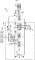
- FIG. 1 is a schematic view showing an electric vehicle disclosed in the conventional literature.
- an electric vehicle 10 includes a pre-charge and voltage supply system 30, a DC-AC inverter 40, a vehicle motor system 50, a vehicle controller 52 and the like.
- the system 30 includes a first battery 60, a voltage sensor 70, a contactor 80, a contactor driver 90, a voltage sensor 110, a DC-DC voltage converter 120 and a second battery 130.
- the first battery 60 is configured to supply power for driving the vehicle motor system 50.
- the second battery 130 is configured to supply power for pre-charging a capacitor in the DC-AC inverter 40.
- the electric vehicle 10 disclosed in the conventional literature essentially includes the second battery 130 for pre-charging a capacitor in the DC-AC inverter 40, which increases the cost and limits the space.
- the conventional literature fails to suggest a technique for emergency control of the electric vehicle 10 while the contactor 80 is abnormally operating.
- the present disclosure is designed to solve the problems of the related art, and therefore the present disclosure is directed to providing a driving circuit for not only pre-charging a capacitor in an inverter but also performing emergency driving, by using a single battery provided in an electric vehicle, and a control method thereof.
- a driving circuit for an electric vehicle having a battery pack and an inverter comprising: a first contactor connected between a first terminal of the battery pack and a first terminal of a capacitor included in the inverter; a second contactor and a current limiting circuit connected to the first contactor in parallel; and a control unit configured to control operations of the first contactor and the second contactor, wherein the second contactor and the current limiting circuit are connected to each other in series, wherein the current limiting circuit includes at least one resistor, wherein the control unit outputs a first control signal when the first contactor is normally operating and outputs a second control signal when the first contactor is abnormally operating, and wherein the first control signal induces the first contactor to turn on, and the second control signal induces the second contactor to turn on.
- the driving circuit may further comprise a third contactor connected between a second terminal of the battery pack and a second terminal of the capacitor.
- the control unit may output a third control signal together with the second control signal when the first contactor is normally operating.
- the third control signal may induce the third contactor to turn on.
- control unit may stop outputting the first control signal when the first contactor is abnormally operating.
- the driving circuit may further comprise a voltage measuring circuit configured to measure voltages at both ends of the first contactor.
- control unit may determine whether the first contactor is normally operating, based on the voltages at both ends of the first contactor measured by the voltage measuring circuit, while the first control signal is being output.
- the current limiting circuit includes a first current limiting unit connected to the second contactor in series; and a second current limiting unit connected to the first current limiting unit in parallel.
- the first current limiting unit includes a first switch and a first resistor connected to each other in series.
- the second current limiting unit includes a second switch and a second resistor connected to each other in series. In this case, resistance of the first resistor may be different from resistance of the second resistor.
- control unit is configured to turn on at least one of the first switch and the second switch when the first contactor is abnormally operating.
- control unit is configured to turn on at least one of the first switch and the second switch based on running information of the electric vehicle.
- the running information includes at least one of running speed, geographic position and body inclination of the electric vehicle.
- control unit is configured to output a fourth control signal together with the second control signal when resistance of the first resistor is greater than resistance of the second resistor and the running speed is lower than a reference speed when the first contactor is abnormally operating.
- the first switch is configured to be turned on by the fourth control signal.
- control unit may output a fifth control signal together with the second control signal when resistance of the first resistor is greater than resistance of the second resistor and the running speed is equal to or higher than a reference speed when the first contactor is abnormally operating.
- the second switch may turn on by the fifth control signal.
- an electric vehicle comprising the driving circuit.
- a control method comprising notably: by the control unit, outputting a first control signal; by the control unit, determining whether the first contactor is normally operating while the first control signal is being output; by the control unit, outputting the second control signal while it is determined that the first contactor is abnormally operating; and turning on the second contactor by the second control signal to electrically connect the first terminal of the battery pack and the first terminal of the capacitor.
- the driving circuit may not only pre-charge a capacitor in an inverter but also perform emergency driving, by using a single battery provided in an electric vehicle.
- the magnitude of current supplied from a battery pack to an electric motor may be adjusted based on running information of the electric vehicle.
- control unit refers to a unit that processes at least one function or operation, and may be implemented by hardware, software, or a combination of hardware and software.
- FIG. 2 is a block diagram showing a functional configuration of an electric vehicle 1 having the driving circuit 10 according to an embodiment of the present disclosure.
- the electric vehicle 1 may include a sensing device 2, a battery pack 100, a driving circuit 10, a load 20, voltage output lines 11 to 16 and electric lines 31 to 38.
- the driving circuit 10 includes a first contactor 210, a second contactor 220, , a current limiting circuit 240 and a control unit 400. It may further comprise a third contactor 230 and a voltage measuring circuit 300.
- the battery pack 100 is configured to output an operational voltage V H of a predetermined range in order to operate the load 20.
- the battery pack 100 may include a plurality of battery modules 110, 120 electrically connected to each other in series. At this time, each of the battery modules 110, 120 may be configured to include at least one unit cell.
- the load 20 may include an inverter 21 and an electric motor 22. After a capacitor 21a is completely pre-charged, while the connectors 212, 232 are simultaneously at a closed operational position, a first terminal and a second terminal of the inverter 21 may be electrically connected to a first terminal 130 and a second terminal 140 of the battery pack 100, respectively. Accordingly, the inverter 21 may supply an operational voltage of a predetermined range to the electric motor 22 through an electric line 38. For example, the inverter 21 may convert a DC voltage supplied from the battery pack 100 into an AC voltage and then supply the AC voltage to the electric motor 22. The pre-charge operation for the capacitor 21a will be described later.
- the sensing device 2 includes a plurality of sensors for measuring or calculating different parameters.
- the sensing device 2 may transmit a signal S1, which represents a measurement value collected by the sensors included therein, to the control unit 400.
- the sensing device 2 may include at least one of a speed sensor, a position sensor and an inclination sensor.
- the speed sensor may measure a running speed of the electric vehicle 1 and provide a signal representing the measured running speed to the control unit 400.
- the position sensor may provide a signal corresponding to the geographic position of the electric vehicle 1 to the control unit 400.
- the position sensor may be a GPS receiver.
- the inclination sensor may provide a signal representing the body inclination of the electric vehicle 1 to the control unit 400.
- the information provided from the sensing device 2 to the control unit 400 may be called 'running information'.
- the running information may include information about the running speed, the geographic position or the body inclination of the electric vehicle 1, and the signal S1 representing the running information may be received by the control unit 400 and utilized to control the driving circuit 10.
- the control unit 400 controls overall operations of the driving circuit 10.
- the control unit 400 is configured to control at least one operational position of the first contactor 210, the second contactor 220 and the third contactor 230.
- the control unit 400 may include a microprocessor 410, a memory 420 and at least three voltage output units 431 to 433.
- the microprocessor 410 may be implemented in hardware by using at least one of application specific integrated circuits (ASICs), digital signal processors (DSPs), digital signal processing devices (DSPDs), programmable logic devices (PLDs), field programmable gate arrays (FPGAs), processors, micro-controllers, and other electronic units for performing other functions.
- ASICs application specific integrated circuits
- DSPs digital signal processors
- DSPDs digital signal processing devices
- PLDs programmable logic devices
- FPGAs field programmable gate arrays
- processors micro-controllers, and other electronic units for performing other functions.
- the microprocessor 410 may control operations of the voltage measuring circuit 300. As shown in FIG. 4 , if the current limiting circuit 240 includes a switching element, the microprocessor 410 may control operations of the switching elements included in the current limiting circuit 240 individually.
- the memory 420 may store various data and commands required for the overall operations of the driving circuit 10. With reference to data and commands stored in the memory 420, the microprocessor 410 may output signals for controlling operational positions of the first contactor 210, the second contactor 220 and the third contactor 230 or execute processes for determining whether the first contactor 210, the second contactor 220 and the third contactor 230 operate normally.
- the memory may include a storage medium of at least one of a flash memory type, a hard disk type, a solid state disk (SSD) type, a silicon disk drive (SDD) type, a multimedia card micro type, a random access memory (RAM) type, a static random access memory (SRAM) type, a read-only memory (ROM) type, an electrically erasable programmable read-only memory (EEPROM) type, and a programmable read-only memory (PROM).
- a storage medium of at least one of a flash memory type a hard disk type, a solid state disk (SSD) type, a silicon disk drive (SDD) type, a multimedia card micro type, a random access memory (RAM) type, a static random access memory (SRAM) type, a read-only memory (ROM) type, an electrically erasable programmable read-only memory (EEPROM) type, and a programmable read-only memory (PROM).
- the first voltage output unit 431 may output a voltage of a predetermined level to the first voltage output line 11 and the second voltage output line 12, as a response to the signal provided from the microprocessor 410.
- the first voltage output unit 431 may output a voltage of a first level to the first voltage output line 11 and output a voltage of a second level to the second voltage output line 12.
- the second voltage output unit 432 may output a voltage of a predetermined level to the third voltage output line 13 and the fourth voltage output line 14, as a response to the signal provided from the microprocessor 410.
- the second voltage output unit 432 may output a voltage of a third level to the third voltage output line 13 and output a voltage of a fourth level to the fourth voltage output line 14.
- the third voltage output unit 433 may output a voltage of a predetermined level to the fifth voltage output line 15 and the sixth voltage output line 16, as a response to the signal provided from the microprocessor 410.
- the third voltage output unit 433 may output a voltage of a fifth level to the fifth voltage output line 15 and output a voltage of a sixth level to the sixth voltage output line 16.
- the first contactor 210 may include a first contactor coil 211 and a first connector 212.
- the first contactor 210 is electrically connected to the battery pack 100 and the load 20.
- the first contactor 210 is connected in series between the first terminal 130 of the battery pack 100 and the first terminal of the capacitor 21a.
- the first terminal 130 of the battery pack 100 may be a terminal 130 having a relatively higher potential, between both terminals 130, 140 of the battery pack 100.
- the first terminal 130 of the battery pack 100 may be connected to one end of the first connector 212 through the electric line 31.
- the other end of the first connector 212 may be electrically connected to the first terminal of the capacitor 21a through the electric line 32.
- One end of the first contactor coil 211 may be electrically connected to the first voltage output line 11, and the other end of the first contactor coil 211 may be electrically connected to the second voltage output line 12.
- the control unit 400 outputs a first control signal to turn on the first contactor 210.
- the first control signal induces the first contactor 210 to turn on.
- the first control signal may be provided to the first contactor coil 211 through the first voltage output line 11 and the second voltage output line 12.
- the control unit 400 may output a voltage of a predetermined level to the first voltage output line 11 and the second voltage output line 12, respectively to apply power to the first contactor coil 211.
- the level of the voltage output to one end of the first contactor coil 211 through the first voltage output line 11 may be different from the level of the voltage output to the other end of the first contactor coil 211 through the second voltage output line 12. Due to the current flowing through the first contactor coil 211 to which power is applied, the first connector 212 comes to a closed operational position. While the first connector 212 is at the closed operational position, the battery pack 100 and the load 20 may be electrically connected.
- the control unit 400 may cut the power supply to the first contactor coil 211 by stopping the output of voltage to at least one of the first voltage output line 11 and the second voltage output line 12. If the power supply to the first contactor coil 211 is cut, the first connector 212 comes to an open operational position. While the first connector 212 is at the open operational position, the battery pack 100 and the load 20 may be electrically disconnected.
- the first contactor 210 may also be called a 'main contactor'.
- the second contactor 220 may include a second contactor coil 221 and a second connector 222.
- the second contactor 220 is electrically connected to the first contactor 210 in parallel, together with the current limiting circuit 240 connected there to in series.
- one end of the second connector 222 may be electrically connected to the electric line 31 through the electric line 34.
- the other end of the second connector 222 may be electrically connected to the electric line 32 through the current limiting circuit 240 and the electric line 35.
- Each resistor included in the current limiting circuit 240 may be called a 'pre-charge resistor' .
- the current limiting circuit 240 includes two resistors, any one of them may be called a first pre-charge resistor, and the other resistor may be called a second pre-charge resistor.
- One end of the second contactor coil 221 may be electrically connected to the third voltage output line 13, and the other end of the second contactor coil 221 may be electrically connected to the fourth voltage output line 14.
- the control unit 400 outputs a second control signal to turn on the second contactor 220.
- the second control signal induces the second contactor 220 to turn on.
- the second control signal may be provided to the second contactor coil 221 through the third voltage output line 13 and the fourth voltage output line 14.
- the control unit 400 may apply power to the second contactor coil 221 by outputting a voltage of a predetermined level to the third voltage output line 13 and the fourth voltage output line 14, respectively.
- the level of the voltage output to one end of the second contactor coil 221 through the third voltage output line 13 may be different from the level of the voltage output to the other end of the second contactor coil 221 through the fourth voltage output line 14.
- the second connector 222 Due to the current flowing through the second contactor coil 221 to which power is applied, the second connector 222 comes to a closed operational position. While the second connector 222 is at the closed operational position, the battery pack 100 and the load 20 may be electrically connected.
- the control unit 400 may cut the power supply to the second contactor coil 221 by stopping the output of voltage to at least one of the third voltage output line 13 and the fourth voltage output line 14. If the power supply to the second contactor coil 221 is cut, current does not flow through the second contactor coil 221, and thus the second connector 222 comes to an open operational position. While the second connector 222 is at the open operational position, the battery pack 100 and the load 20 may be electrically disconnected.
- the second contactor 220 may also be called a 'pre-charge contactor'.
- the third contactor 230 may include a third contactor coil 231 and a third connector 232.
- the third contactor 230 may be electrically connected to the battery pack 100 and the load 20 in series.
- one end of the third connector 232 may be electrically connected to the second terminal 140 of the battery pack 100 through the electric line 36.
- the other end of the third connector 232 may be electrically connected to the second terminal of the capacitor 21a through the electric line 37.
- One end of the third contactor coil 231 may be electrically connected to the fifth voltage output line 15, and the other end of the third contactor coil 231 may be electrically connected to the sixth voltage output line 16.
- the control unit 400 may output a third control signal to turn on the third contactor 230.
- the third control signal induces the third contactor 230 to turn on.
- the third control signal may be provided to the third contactor coil 231 through the fifth voltage output line 15 and the sixth voltage output line 16.
- the control unit 400 may apply power to the third contactor coil 231 by outputting a voltage of a predetermined level to the fifth voltage output line 15 and the sixth voltage output line 16, respectively. At this time, the level of the voltage output to one end of the third contactor coil 231 through the fifth voltage output line 15 may be different from the level of the voltage output to the other end of the third contactor coil 231 through the sixth voltage output line 16.
- the third connector 232 Due to the current flowing through the third contactor coil 231 to which power is applied, the third connector 232 comes to a closed operational position. While the third connector 232 is at the closed operational position, the second terminal of the battery pack 100 and the second terminal of the capacitor 21a may be electrically connected.
- the control unit 400 may cut the power supply to the third contactor coil 231 by stopping the output of voltage to at least one of the fifth voltage output line 15 and the sixth voltage output line 16. If the power supply to the third contactor coil 231 is cut, current does not flow through the third contactor coil 231, and thus the third connector 232 comes to an open operational position. While the third connector 232 is at the open operational position, the second terminal of the battery pack 100 and the second terminal of the capacitor 21a may be electrically disconnected.
- the third contactor 230 may also be called a 'ground contactor'.
- the driving circuit 10 may supply power, fed from the battery pack 100, to the capacitor 21a by using the current limiting circuit 240 while the first connector 212 is at the open operational position and the second connector 222 and the third connector 232 are at the closed operational position. Accordingly, before the first connector 212 comes to the closed operational position, pre-charge may be performed to the capacitor 21a.
- the control unit 400 After the capacitor 21a is pre-charged over a target value, the control unit 400 induces the first connector 212 to come to a closed operational position, so that the magnitude of an instant inrush current when the battery pack 100 having a high voltage is electrically connected to the capacitor 21a may be reduced.
- the driving circuit 10 takes charge of basic operations for pre-charging the capacitor 21a included in the inverter 21 in a state where the first contactor 210 is capable of normally operating, and also advantageously maintains electric connection to supply power from the battery pack 100 to the capacitor 21a during an abnormal operation when the first contactor 210 cannot be at the closed operational position, by using the second contactor 220 and the current limiting circuit 240.
- the first contactor 210 may abnormally operate due to various reasons. For example, if the first contactor coil 211 or the first connector 212 of the first contactor 210 is damaged, even though the first control signal is output from the control unit 400, the first connector 212 will not come to the closed operational position. In another example, even though the first contactor coil 211 and the first connector 212 are not damaged, if the first voltage output line 11 or the second voltage output line 12 is disconnected or the first voltage output unit 431 malfunctions, the first connector 212 will not come to the closed operational position.
- the voltage measuring circuit 300 may be configured to measure a first voltage VI and a second voltage VI, respectively.
- the first voltage VI may represent a difference between the potential of the electric line 31 and the potential of a reference point
- the second voltage V2 may represent a difference between the potential of the electric line 32 and the potential of the reference point.
- the first voltage VI may represent a voltage of one of both ends of the first contactor 210, which is connected to the first terminal 130 of the battery pack 100
- the second voltage V2 may represent a voltage of the other of both ends of the first contactor 210, which is connected to the capacitor 21a.
- the reference point may be the ground or the second terminal 140 of the battery pack 100.
- the voltage measuring circuit 300 may be measure voltages applied to both ends of the first connector 212, based on the first and second voltages VI, V2.
- the voltage applied to both ends of the first contactor 210 may be identical to V1-V2, which is a difference between the first voltage VI and the second voltage V2.
- the voltage measuring circuit 300 may provide a signal S2, which represents the voltage applied to both ends of the first connector 212, to the control unit 400.
- the signal S2 may have a form of a binary value and be output repeatedly at regular intervals.
- control unit 400 may measure the voltage applied to both ends of the first connector 212 by using the voltage measuring circuit 300.
- control unit 400 may measure the voltage applied to both ends of the first connector 212 by using the voltage measuring circuit 300 at least once while the first control signal is being output.
- the first control signal is a signal for guiding the first contactor 210 to turn on.
- the first control signal may correspond to a voltage of a predetermined level, output from the first voltage output line 11 and the second voltage output line 12, respectively.
- the control unit 400 may output the first control signal.
- the first contactor 210 If the first contactor 210 is capable of normally operating, power is applied to the first contactor coil 211 as a response to the first control signal, and thus the first connector 212 will come to a closed operational position. Meanwhile, if the contactor 210 is not capable of normally operating due to a failure or the like, the first connector 212 will come to an open operational position, even though the first control signal is being output.
- the control unit 400 may determine whether the first contactor 210 is normally operating, based on the voltage at both ends of the first contactor 210 measured by the voltage measuring circuit 300. In an embodiment, if the voltage at both ends of the first connector 212 measured while the first control signal is being output is equal to or higher than a predetermined reference voltage, the control unit 400 may determine that the first contactor 210 is operating abnormally.
- control unit 400 may stop the output of the first control signal.
- control unit 400 may output a signal for notifying a user that the first contactor 210 is abnormally operating, through a monitor or a speaker provided at the electric vehicle 1.
- the control unit 400 may determine that the first contactor 210 is normally operating.
- the reference voltage is determined through experiments in advance, and data representing the reference voltage may be stored in the memory 420 in advance.
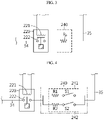
- FIG. 3 is a schematic view showing the current limiting circuit 240 according to an example not forming part of the invention of the present disclosure. For convenience, it is assumed that the third connector 232 depicted in FIG. 2 has a closed operational position.
- the current limiting circuit 240 may include a resistor R.
- one end of the resistor Rp may be electrically connected to the first terminal 130 of the battery pack 100 through the second contactor 220 and the electric line 34.
- the other end of the resistor Rp may be electrically connected to the first terminal of the capacitor 21a through the electric line 35.
- control unit 400 may output a second control signal and a third control signal.
- the second connector 222 comes to a closed operational position
- the third control signal the third connector 232 comes to a closed operational position. Accordingly, while the first contactor 210 is at the open operational position due to a failure or the like (or, while the first connector 212 is not capable to coming to a closed operational position), the first terminal and the second terminal of the capacitor 21a may be electrically connected to the first terminal 130 and the second terminal 140 of the battery pack 100 through the second connector 222 and the third connector 232, respectively. In other words, while the first contactor 210 is abnormally operating, the power supplied from the battery pack 100 may be supplied to the electric motor 22 through the second contactor 220 instead of the first contactor 210, the resistor Rp and the inverter 20. As a result, the electric vehicle 1 may perform emergency driving.
- FIG. 4 is a schematic view showing a current limiting circuit 240 according to another embodiment of the present disclosure which is within the scope of the present invention.
- the current limiting circuit 240 includes a plurality of current limiting units. Hereinafter, for convenience, it is assumed that the current limiting circuit 240 includes two current limiting units 241, 242. Any one current limiting unit included in the current limiting circuit 240 is electrically connected to the other current limiting unit in parallel.
- the first current limiting unit 241 includes a first switch S1 and a first resistor R1. At this time, the first switch S1 and the first resistor R1 are connected to each other in series.
- the second current limiting unit 242 includes a second switch S2 and a second resistor R2, similar to the first current limiting unit 241.
- the second switch S2 and the second resistor R2 are connected to each other in series.
- the first switch Si and the second switch S2 may be a known switching element such as MOFET.
- the resistance of the first resistor R1 may be different from the resistance of the second resistor R2.
- the resistance of the first resistor R1 is greater than the resistance of the second resistor R2.
- the control unit 400 may output a control signal for turning on at least one of the first switch Si and the second switch S2. In detail, if the control unit 400 outputs a fourth control signal, the first switch Si is turned on by the fourth control signal. In addition, if the control unit 400 outputs a fifth control signal, the second switch S2 may turn on by the fifth control signal.
- the fourth control signal and the fifth control signal may be output simultaneously. In another case, while any one of the fourth control signal and the fifth control signal (for example, the fourth control signal) is being output, the output of the other control signal (for example, the fifth control signal) may be stopped. If the fourth control signal and the fifth control signal are output simultaneously, the first switch Si and the second switch S2 turn on, and thus the first resistor R1 and the second resistor R2 may be electrically connected in parallel. If the first resistor R1 and the second resistor R2 are electrically connected in parallel, the first resistor R1 and the second resistor R2 may be expressed as a single equivalent resistance.
- the equivalent resistance obtained by connecting the first resistor R1 and the second resistor R2 in parallel may be 1Q.
- the other conditions for example, temperature
- the current flowing through the current limiting circuit 240 may be increased when the fourth control signal and the fifth control signal are output simultaneously, compared with the case where just any one of the fourth control signal and the fifth control signal is output.
- the control unit 400 may determine whether to output the fourth control signal or the fifth control signal, based on the running information provided from the sensing device 2 of the electric vehicle 1.
- the control unit 400 outputs the fourth control signal together with the second control signal. Because the second connector 222 comes to a closed operational position due to the second control signal and the first switch S1 turns on due to the fourth control signal, the first terminal 130 of the battery pack 100 which is a high potential terminal is electrically connected to the first terminal of the capacitor 21a through the second contactor 220, the first switch S1 and the first resistor R1.
- a reference speed for example, 10 km/h
- the control unit 400 may output the fifth control signal together with the second control signal. Because the second connector 222 comes to a closed operational position due to the second control signal and the second switch S2 turns on due to the fifth control signal, the first terminal 130 of the battery pack 100 which is a high potential terminal may be electrically connected to the first terminal of the capacitor 21a through the second contactor 220, the second switch S2 and the second resistor R2.
- the fact that the running speed of the electric vehicle 1 is lower than the reference speed means that the power demanded to the electric motor 22 is relatively lower in comparison to the case where the running speed is equal to or higher than the reference speed.
- the magnitude of current flowing between the battery pack 100 and the capacitor 21a becomes decreased in comparison to the case where the power from the battery pack 100 is supplied to the inverter 21 through the second resistor R2.
- any one time point while the first contactor 210 is determined to be abnormally operating it may be determined whether the fourth control signal or the fifth control signal is output, based on a geographic position of the electric vehicle 1. For example, if a distance from the current geographic position of the electric vehicle 1 to a closest repair shop is smaller than a reference distance (for example 40 km), the control unit 400 may output the fourth control signal together with the second control signal. Meanwhile, if the distance from the electric vehicle 1 to a closest repair shop is equal to or greater than the reference distance, the control unit 400 may output the fifth control signal together with the second control signal.
- a reference distance for example 40 km
- the data representing the distance from a current geographic position of the electric vehicle 1 to a closest repair shop may be calculated by the control unit 400 or provided from the sensing device 2, the MCU or the like of the electric vehicle 1.
- control unit 400 may output the fourth control signal together with the second control signal. In this case, the output of the first control signal and the fifth control signal may be stopped.
- the control unit 400 may output the fifth control signal of the second control signal. In this case, the output of the first control signal and the fourth control signal may be stopped.
- the fact that the body inclination of the electric vehicle 1 is smaller than the reference angle means that the electric vehicle 1 is running on a gentle road such as a flat land.
- the power demanded to the electric motor 22 may be relatively lower in comparison to the case where the electric vehicle is running on a steep road.
- the magnitude of the current flowing between the battery pack 100 and the capacitor 21a becomes decreased in comparison to the case where the power from the battery pack 100 is supplied to the inverter 21 through the second resistor R2.
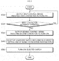
- FIG. 5 is a flowchart for illustrating a control method of the driving circuit 10 according to an embodiment of the present disclosure. For convenience, it is assumed that the control unit 400 is in a state of outputting the third control signal, namely in a state where the third connector 232 has a closed operational position.
- Step S510 the control unit 400 outputs a first control signal.
- the first control signal is a signal for guiding the first contactor 210 to turn on.
- the first control signal may be output according to a command of a driver (for example, by stepping on an accelerator pedal).
- the control unit 400 may output a voltage of a first level through the first voltage output line 11 and output a voltage of a second level through the second voltage output line 12.
- Step 5520 the control unit 400 determines whether the first contactor 210 is normally operating while the first control signal is being output through Step 5510.
- the first connector 212 comes to a closed operational position, and the voltage at both ends of the first contactor 210 measured by the voltage measuring circuit 300 will be smaller than a reference voltage.
- the control unit 400 may determine that the first contactor 210 is capable of normally operating. If the voltage at both ends of the first contactor 210 measured while the first control signal is being output is equal to or greater than the reference voltage, the control unit 400 may determine that the first contactor 210 is abnormally operating.
- Step 5520 is determined as 'YES', the control unit 400 returns to Step 5510. Meanwhile, if Step 5520 is determined as 'NO', the control unit 400 proceeds to Step S530.
- Step 5530 the control unit 400 outputs a second control signal.
- the second control signal is a signal for guiding the second contactor 220 to turn on.
- the control unit 400 may output a voltage of a third level through the third voltage output line 13 and output a voltage of a fourth level through the fourth voltage output line 14.
- the second contactor 220 turning on by the second control signal may electrically connect the battery pack 100 and the load 20.
- the first terminal 130 of the battery pack 100 may be capable of being electrically connected to the first terminal of the capacitor 21a through the second contactor 220 and the current limiting circuit 240.
- the current limiting circuit 240 further includes a first current limiting unit 241 and a second current limiting unit 242, connected to each other in parallel.
- the method may further include Step S540 and Step S550.
- the control unit 440 may select at least one switch included in the current limiting circuit 240, based on the running information of the electric vehicle 1. For example, the control unit 440 may select any one of the first switch 51 and the second switch S2, or select both switches 51, S2.
- the running information may represent information about the running speed, the geographic position or the body inclination of the electric vehicle 1.
- Step S550 the control unit 440 may turn on the switch selected in Step S540.
- the control unit 440 outputs the fourth control signal when the first switch 51 is selected and may output the fifth control signal when the second switch S2 is selected.
- the first switch 51 is turned on by the fourth control signal. In this case, an electric current limited as much as the resistance of the first resistor R1 may be supplied from the battery pack 100 to the inverter 21.
- the second switch S2 may turn on by the fifth control signal. In this case, an electric current limited as much as the resistance of the second resistor R2 may be supplied from the battery pack 100 to the inverter 21.
- the power is supplied from the battery pack 100 to the inverter 20 through the second contactor 220 and the current limiting circuit 240, and the inverter 20 may convert the power supplied from the battery pack 100 into a power demanded to the electric motor 22.
Landscapes
- Engineering & Computer Science (AREA)
- Power Engineering (AREA)
- Mechanical Engineering (AREA)
- Transportation (AREA)
- Sustainable Energy (AREA)
- Sustainable Development (AREA)
- Life Sciences & Earth Sciences (AREA)
- General Physics & Mathematics (AREA)
- Physics & Mathematics (AREA)
- Chemical & Material Sciences (AREA)
- Combustion & Propulsion (AREA)
- Manufacturing & Machinery (AREA)
- Chemical Kinetics & Catalysis (AREA)
- Electrochemistry (AREA)
- General Chemical & Material Sciences (AREA)
- Electric Propulsion And Braking For Vehicles (AREA)
- Charge And Discharge Circuits For Batteries Or The Like (AREA)
- Direct Current Feeding And Distribution (AREA)
Priority Applications (1)
| Application Number | Priority Date | Filing Date | Title |
|---|---|---|---|
| PL17815599T PL3354511T3 (pl) | 2016-06-22 | 2017-05-16 | Układ napędowy dla pojazdu elektrycznego i sposób jego sterowania |
Applications Claiming Priority (2)
| Application Number | Priority Date | Filing Date | Title |
|---|---|---|---|
| KR1020160078193A KR102145524B1 (ko) | 2016-06-22 | 2016-06-22 | 전기 자동차용 구동 회로 및 그 제어 방법 |
| PCT/KR2017/005064 WO2017222186A1 (ko) | 2016-06-22 | 2017-05-16 | 전기 자동차용 구동 회로 및 그 제어 방법 |
Publications (3)
| Publication Number | Publication Date |
|---|---|
| EP3354511A1 EP3354511A1 (en) | 2018-08-01 |
| EP3354511A4 EP3354511A4 (en) | 2018-12-19 |
| EP3354511B1 true EP3354511B1 (en) | 2022-03-30 |
Family
ID=60784516
Family Applications (1)
| Application Number | Title | Priority Date | Filing Date |
|---|---|---|---|
| EP17815599.0A Active EP3354511B1 (en) | 2016-06-22 | 2017-05-16 | Driving circuit for electric vehicle and control method therefor |
Country Status (7)
| Country | Link |
|---|---|
| US (1) | US10807474B2 (ko) |
| EP (1) | EP3354511B1 (ko) |
| JP (1) | JP6616902B2 (ko) |
| KR (1) | KR102145524B1 (ko) |
| CN (1) | CN108349406B (ko) |
| PL (1) | PL3354511T3 (ko) |
| WO (1) | WO2017222186A1 (ko) |
Families Citing this family (12)
| Publication number | Priority date | Publication date | Assignee | Title |
|---|---|---|---|---|
| JP7090229B2 (ja) * | 2017-03-30 | 2022-06-24 | パナソニックIpマネジメント株式会社 | 車両用蓄電装置 |
| JP7020952B2 (ja) * | 2018-02-13 | 2022-02-16 | 本田技研工業株式会社 | 電源システム |
| US11277020B2 (en) | 2018-03-08 | 2022-03-15 | Vitesco Technologies GmbH | Motor vehicle having an AC charging device with a precharge circuit for a smoothing capacitor |
| KR102423888B1 (ko) * | 2018-08-13 | 2022-07-20 | 주식회사 엘지에너지솔루션 | 스위치 제어 장치 |
| KR102593366B1 (ko) * | 2018-10-18 | 2023-10-23 | 주식회사 엘지에너지솔루션 | 다중 신호 측정 시스템 및 방법 |
| KR102654842B1 (ko) * | 2018-12-10 | 2024-04-05 | 현대자동차주식회사 | 차량의 배터리 시스템 및 그의 진단 방법 |
| KR20210077065A (ko) * | 2019-12-16 | 2021-06-25 | 현대자동차주식회사 | 차량용 pra 열화 제어 시스템 및 그의 pra 열화 제어 방법 |
| US12006015B2 (en) * | 2020-05-13 | 2024-06-11 | Liquid Propulsion, Llc | Thrust system for steering marine vessels |
| CN111525656B (zh) * | 2020-06-03 | 2022-03-18 | 桑顿新能源科技(长沙)有限公司 | 电池电能回馈系统以及车辆 |
| CN112078368B (zh) * | 2020-08-03 | 2022-03-29 | 湖南中联重科智能高空作业机械有限公司 | 回馈电流控制装置及高空作业车 |
| KR20230054153A (ko) * | 2021-10-15 | 2023-04-24 | 주식회사 엘지에너지솔루션 | 배터리 관리 장치 및 그것의 동작 방법 |
| CN114030373B (zh) * | 2021-11-02 | 2024-05-14 | 深圳麦格米特电气股份有限公司 | 一种电源处理电路、车载充电机及充电枪识别方法 |
Family Cites Families (47)
| Publication number | Priority date | Publication date | Assignee | Title |
|---|---|---|---|---|
| JPH0669270B2 (ja) * | 1989-08-10 | 1994-08-31 | いすゞ自動車株式会社 | コンデンサの充電装置 |
| JP3191481B2 (ja) * | 1993-04-21 | 2001-07-23 | 松下電器産業株式会社 | 自動車用空調装置 |
| JP3555534B2 (ja) | 2000-01-24 | 2004-08-18 | 株式会社デンソー | 組み電池の電圧検出装置 |
| JP3945630B2 (ja) * | 2002-01-10 | 2007-07-18 | パナソニック・イーブイ・エナジー株式会社 | 電池電源装置のリレー接点溶着検査方法 |
| US6768621B2 (en) * | 2002-01-18 | 2004-07-27 | Solectria Corporation | Contactor feedback and precharge/discharge circuit |
| JP4543844B2 (ja) * | 2004-09-10 | 2010-09-15 | トヨタ自動車株式会社 | 電源回路の制御装置 |
| KR100694062B1 (ko) | 2004-10-27 | 2007-03-12 | 삼성전자주식회사 | 다중 배터리 충전 장치 및 제어 방법 |
| JP4466327B2 (ja) | 2004-11-04 | 2010-05-26 | トヨタ自動車株式会社 | 車両用電源装置 |
| JP4671336B2 (ja) | 2005-05-09 | 2011-04-13 | 株式会社小松製作所 | モータ駆動装置 |
| JP4804994B2 (ja) * | 2006-04-05 | 2011-11-02 | 株式会社小松製作所 | フォークリフト用電源装置 |
| KR100877854B1 (ko) | 2007-03-27 | 2009-01-13 | 현대자동차주식회사 | 하이브리드 차량의 전력변환장치 비상구동방법 |
| CN101073990B (zh) | 2007-06-22 | 2011-06-01 | 深圳先进技术研究院 | 一种具有安全保护装置的电动车供电系统及其控制方法 |
| JP4288333B1 (ja) | 2007-12-18 | 2009-07-01 | トヨタ自動車株式会社 | 車両の電源装置 |
| KR101103616B1 (ko) * | 2008-01-07 | 2012-01-09 | 에스케이이노베이션 주식회사 | 인터락 스위치를 이용한 프리-차지 저항 보호 회로 장치 |
| JP4978476B2 (ja) | 2008-01-09 | 2012-07-18 | 株式会社デンソー | 電源状態検出装置 |
| KR101068583B1 (ko) | 2009-01-09 | 2011-09-30 | 부산대학교 산학협력단 | 하이브리드 자동차의 안전 시스템 및 그 제어방법 |
| US8040139B2 (en) * | 2009-02-16 | 2011-10-18 | Maxim Integrated Products, Inc. | Fault detection method for detecting leakage paths between power sources and chassis |
| JP5221468B2 (ja) * | 2009-02-27 | 2013-06-26 | 株式会社日立製作所 | 電池監視装置 |
| JP5656415B2 (ja) * | 2009-03-26 | 2015-01-21 | プライムアースEvエナジー株式会社 | 二次電池の状態判定装置及び制御装置 |
| WO2011028703A2 (en) * | 2009-09-01 | 2011-03-10 | Boston-Power, Inc. | Safety and performance optimized controls for large scale electric vehicle battery systems |
| US8550405B2 (en) * | 2009-09-29 | 2013-10-08 | Busek Company, Inc. | Solar powered spacecraft power system for a hall effect thruster |
| KR101079938B1 (ko) * | 2009-10-13 | 2011-11-04 | 대성전기공업 주식회사 | 차량용 반도체 스위치 구동 회로 |
| KR101057542B1 (ko) * | 2010-01-26 | 2011-08-17 | 에스비리모티브 주식회사 | 배터리 관리 시스템 및 그 구동 방법 |
| KR101057547B1 (ko) * | 2010-01-26 | 2011-08-17 | 에스비리모티브 주식회사 | 배터리 관리 시스템 및 그 구동 방법 |
| JP5584927B2 (ja) * | 2010-06-04 | 2014-09-10 | 日立オートモティブシステムズ株式会社 | 電池制御装置および蓄電装置 |
| US8655535B2 (en) * | 2010-07-09 | 2014-02-18 | Lg Electronics Inc. | Electric vehicle and method for controlling same |
| US8288031B1 (en) * | 2011-03-28 | 2012-10-16 | Lg Chem, Ltd. | Battery disconnect unit and method of assembling the battery disconnect unit |
| KR101255248B1 (ko) * | 2011-07-04 | 2013-04-16 | 로베르트 보쉬 게엠베하 | 배터리 관리 시스템 및 이의 제어 방법 |
| US9024468B2 (en) | 2012-07-02 | 2015-05-05 | Lg Chem, Ltd. | Driver circuit for an electric vehicle and a diagnostic method for determining when a voltage driver is shorted to a ground voltage |
| US9266433B2 (en) * | 2012-07-23 | 2016-02-23 | Ford Global Technologies, Llc | Low cost charger circuit with precharge |
| DE102012213057B4 (de) * | 2012-07-25 | 2020-10-29 | Robert Bosch Gmbh | Verfahren zum Steuern eines Batteriesystems, Batteriesystem und Kraftfahrzeug |
| KR20140070148A (ko) | 2012-11-30 | 2014-06-10 | 에스케이이노베이션 주식회사 | 배터리 전류 측정 장치 및 그 방법 |
| KR101470098B1 (ko) | 2012-12-18 | 2014-12-05 | 현대자동차주식회사 | 차량의 릴레이 고장진단 장치 및 방법 |
| KR101563867B1 (ko) * | 2013-02-06 | 2015-10-28 | 엘지전자 주식회사 | 충전 장치, 및 이를 구비하는 전기 차량 |
| CA2904199C (en) | 2013-02-26 | 2019-07-02 | Zonit Structured Solutions, Llc | Parallel redundant power distribution |
| US10464507B2 (en) | 2013-03-07 | 2019-11-05 | Samsung Sdi Co., Ltd. | Battery management system and switching method thereof |
| JP6191315B2 (ja) * | 2013-08-02 | 2017-09-06 | 株式会社ジェイテクト | 電源回路の異常検出方法 |
| US9726725B2 (en) * | 2013-08-02 | 2017-08-08 | Jtekt Corporation | Power circuit abnormality detection method |
| KR101717611B1 (ko) | 2013-09-04 | 2017-03-17 | 한온시스템 주식회사 | 차량용 공조장치 |
| US9925878B2 (en) * | 2013-09-26 | 2018-03-27 | Ford Global Technologies, Llc | Bus pre-charge control using a buck converter |
| US9209635B2 (en) * | 2013-12-02 | 2015-12-08 | Lg Chem, Ltd. | Pre-charging system for a capacitor in a voltage inverter for an electric motor |
| US9214888B2 (en) * | 2013-12-20 | 2015-12-15 | Lg Chem, Ltd. | Pre-charging system for a capacitor in a voltage inverter for an electric motor |
| KR101551035B1 (ko) * | 2013-12-30 | 2015-09-08 | 현대자동차주식회사 | 프리 차지 중 고장 진단 방법 |
| JP5958477B2 (ja) * | 2014-01-22 | 2016-08-02 | 株式会社豊田自動織機 | インバータ装置 |
| US9413184B2 (en) | 2014-03-21 | 2016-08-09 | Lg Chem, Ltd. | Pre-charging and voltage supply system for a DC-AC inverter |
| KR102302783B1 (ko) * | 2014-07-25 | 2021-09-16 | 현대모비스 주식회사 | 차량 구동 시스템 및 방법 |
| CN110061477B (zh) * | 2014-12-24 | 2021-06-29 | 株式会社杰士汤浅国际 | 电源保护装置、电源装置、开关故障诊断方法及记录介质 |
-
2016
- 2016-06-22 KR KR1020160078193A patent/KR102145524B1/ko active IP Right Grant
-
2017
- 2017-05-16 JP JP2018529548A patent/JP6616902B2/ja active Active
- 2017-05-16 WO PCT/KR2017/005064 patent/WO2017222186A1/ko active Application Filing
- 2017-05-16 CN CN201780003750.6A patent/CN108349406B/zh active Active
- 2017-05-16 EP EP17815599.0A patent/EP3354511B1/en active Active
- 2017-05-16 PL PL17815599T patent/PL3354511T3/pl unknown
- 2017-05-16 US US15/765,626 patent/US10807474B2/en active Active
Non-Patent Citations (1)
| Title |
|---|
| None * |
Also Published As
| Publication number | Publication date |
|---|---|
| KR20180000234A (ko) | 2018-01-02 |
| JP6616902B2 (ja) | 2019-12-04 |
| WO2017222186A1 (ko) | 2017-12-28 |
| JP2018538774A (ja) | 2018-12-27 |
| CN108349406B (zh) | 2021-03-30 |
| PL3354511T3 (pl) | 2022-06-13 |
| EP3354511A1 (en) | 2018-08-01 |
| EP3354511A4 (en) | 2018-12-19 |
| US20190077267A1 (en) | 2019-03-14 |
| CN108349406A (zh) | 2018-07-31 |
| KR102145524B1 (ko) | 2020-08-18 |
| US10807474B2 (en) | 2020-10-20 |
Similar Documents
| Publication | Publication Date | Title |
|---|---|---|
| EP3354511B1 (en) | Driving circuit for electric vehicle and control method therefor | |
| JP6155569B2 (ja) | 電源システム | |
| US10903678B2 (en) | Apparatus and method for providing bidirectional voltage support | |
| JP5865013B2 (ja) | 車両用の電源装置及びこの電源装置を備える車両 | |
| KR101673822B1 (ko) | 친환경 차량의 릴레이 융착 검출 장치 및 그 방법 | |
| US10913361B2 (en) | Battery temperature control system and method | |
| EP2879900B1 (en) | Electrical storage system | |
| JP6722058B2 (ja) | 電源システムの制御装置 | |
| JP5202918B2 (ja) | 電池電圧調整装置 | |
| JP6598542B2 (ja) | 電源装置および電源装置の制御方法 | |
| JP5104648B2 (ja) | 車両の電源装置およびその制御方法 | |
| KR20170097481A (ko) | 컨택터의 상태를 진단하는 충방전 시스템 및 방법 | |
| KR101866063B1 (ko) | 보조배터리의 릴레이 제어 시스템 및 그 방법 | |
| JP2017508436A (ja) | Dc−acインバータに対するプリチャージ及び電圧供給システム | |
| JP2013205257A (ja) | 電源装置、及びこの電源装置を備える車両並びに蓄電装置 | |
| JP2006238509A (ja) | 電動車輌の制御装置、電動車輌の制御方法、プログラム及びコンピュータ可読記録媒体 | |
| US11977117B2 (en) | Battery electromechanical switching device diagnostics system and methods | |
| US20130076519A1 (en) | Apparatus and method for controlling charging and discharging of batteries | |
| KR20190073925A (ko) | 프리차지 장치 및 방법 | |
| JP2008125159A (ja) | 電源装置 | |
| JP2011054542A (ja) | リチウム二次電池の充電システム | |
| JP2008172908A (ja) | 車両用電源装置 | |
| WO2017191818A1 (ja) | 電源装置 | |
| KR102702762B1 (ko) | 릴레이 진단 장치 및 방법 | |
| CN108698548B (zh) | 车载电源用的充电率监视装置以及车载电源系统 |
Legal Events
| Date | Code | Title | Description |
|---|---|---|---|
| STAA | Information on the status of an ep patent application or granted ep patent |
Free format text: STATUS: THE INTERNATIONAL PUBLICATION HAS BEEN MADE |
|
| PUAI | Public reference made under article 153(3) epc to a published international application that has entered the european phase |
Free format text: ORIGINAL CODE: 0009012 |
|
| STAA | Information on the status of an ep patent application or granted ep patent |
Free format text: STATUS: REQUEST FOR EXAMINATION WAS MADE |
|
| 17P | Request for examination filed |
Effective date: 20180424 |
|
| AK | Designated contracting states |
Kind code of ref document: A1 Designated state(s): AL AT BE BG CH CY CZ DE DK EE ES FI FR GB GR HR HU IE IS IT LI LT LU LV MC MK MT NL NO PL PT RO RS SE SI SK SM TR |
|
| AX | Request for extension of the european patent |
Extension state: BA ME |
|
| A4 | Supplementary search report drawn up and despatched |
Effective date: 20181116 |
|
| RIC1 | Information provided on ipc code assigned before grant |
Ipc: B60L 3/04 20060101ALI20181109BHEP Ipc: G01R 19/165 20060101ALI20181109BHEP Ipc: B60L 3/06 20060101ALI20181109BHEP Ipc: G01R 31/00 20060101ALI20181109BHEP Ipc: B60L 11/18 20060101AFI20181109BHEP Ipc: G01R 31/36 20060101ALI20181109BHEP Ipc: B60L 3/00 20060101ALI20181109BHEP |
|
| DAV | Request for validation of the european patent (deleted) | ||
| DAX | Request for extension of the european patent (deleted) | ||
| REG | Reference to a national code |
Ref country code: DE Ref legal event code: R079 Ref document number: 602017055305 Country of ref document: DE Free format text: PREVIOUS MAIN CLASS: B60L0011180000 Ipc: B60L0003060000 |
|
| GRAP | Despatch of communication of intention to grant a patent |
Free format text: ORIGINAL CODE: EPIDOSNIGR1 |
|
| STAA | Information on the status of an ep patent application or granted ep patent |
Free format text: STATUS: GRANT OF PATENT IS INTENDED |
|
| RIC1 | Information provided on ipc code assigned before grant |
Ipc: G01R 31/36 20200101ALI20200331BHEP Ipc: B60L 50/60 20190101ALI20200331BHEP Ipc: G01R 31/00 20060101ALI20200331BHEP Ipc: G01R 19/165 20060101ALI20200331BHEP Ipc: B60L 3/06 20060101AFI20200331BHEP Ipc: B60L 3/00 20190101ALI20200331BHEP Ipc: B60L 3/04 20060101ALI20200331BHEP |
|
| INTG | Intention to grant announced |
Effective date: 20200429 |
|
| GRAS | Grant fee paid |
Free format text: ORIGINAL CODE: EPIDOSNIGR3 |
|
| GRAJ | Information related to disapproval of communication of intention to grant by the applicant or resumption of examination proceedings by the epo deleted |
Free format text: ORIGINAL CODE: EPIDOSDIGR1 |
|
| STAA | Information on the status of an ep patent application or granted ep patent |
Free format text: STATUS: REQUEST FOR EXAMINATION WAS MADE |
|
| STAA | Information on the status of an ep patent application or granted ep patent |
Free format text: STATUS: EXAMINATION IS IN PROGRESS |
|
| 17Q | First examination report despatched |
Effective date: 20200824 |
|
| INTC | Intention to grant announced (deleted) | ||
| STAA | Information on the status of an ep patent application or granted ep patent |
Free format text: STATUS: EXAMINATION IS IN PROGRESS |
|
| GRAP | Despatch of communication of intention to grant a patent |
Free format text: ORIGINAL CODE: EPIDOSNIGR1 |
|
| STAA | Information on the status of an ep patent application or granted ep patent |
Free format text: STATUS: GRANT OF PATENT IS INTENDED |
|
| INTG | Intention to grant announced |
Effective date: 20210924 |
|
| RAP1 | Party data changed (applicant data changed or rights of an application transferred) |
Owner name: LG ENERGY SOLUTION LTD. |
|
| GRAS | Grant fee paid |
Free format text: ORIGINAL CODE: EPIDOSNIGR3 |
|
| GRAF | Information related to payment of grant fee modified |
Free format text: ORIGINAL CODE: EPIDOSCIGR3 |
|
| GRAA | (expected) grant |
Free format text: ORIGINAL CODE: 0009210 |
|
| STAA | Information on the status of an ep patent application or granted ep patent |
Free format text: STATUS: THE PATENT HAS BEEN GRANTED |
|
| AK | Designated contracting states |
Kind code of ref document: B1 Designated state(s): AL AT BE BG CH CY CZ DE DK EE ES FI FR GB GR HR HU IE IS IT LI LT LU LV MC MK MT NL NO PL PT RO RS SE SI SK SM TR |
|
| RAP3 | Party data changed (applicant data changed or rights of an application transferred) |
Owner name: LG ENERGY SOLUTION, LTD. |
|
| REG | Reference to a national code |
Ref country code: GB Ref legal event code: FG4D |
|
| REG | Reference to a national code |
Ref country code: CH Ref legal event code: EP |
|
| REG | Reference to a national code |
Ref country code: AT Ref legal event code: REF Ref document number: 1478882 Country of ref document: AT Kind code of ref document: T Effective date: 20220415 |
|
| REG | Reference to a national code |
Ref country code: DE Ref legal event code: R096 Ref document number: 602017055305 Country of ref document: DE |
|
| REG | Reference to a national code |
Ref country code: IE Ref legal event code: FG4D |
|
| REG | Reference to a national code |
Ref country code: LT Ref legal event code: MG9D |
|
| PG25 | Lapsed in a contracting state [announced via postgrant information from national office to epo] |
Ref country code: SE Free format text: LAPSE BECAUSE OF FAILURE TO SUBMIT A TRANSLATION OF THE DESCRIPTION OR TO PAY THE FEE WITHIN THE PRESCRIBED TIME-LIMIT Effective date: 20220330 Ref country code: RS Free format text: LAPSE BECAUSE OF FAILURE TO SUBMIT A TRANSLATION OF THE DESCRIPTION OR TO PAY THE FEE WITHIN THE PRESCRIBED TIME-LIMIT Effective date: 20220330 Ref country code: NO Free format text: LAPSE BECAUSE OF FAILURE TO SUBMIT A TRANSLATION OF THE DESCRIPTION OR TO PAY THE FEE WITHIN THE PRESCRIBED TIME-LIMIT Effective date: 20220630 Ref country code: LT Free format text: LAPSE BECAUSE OF FAILURE TO SUBMIT A TRANSLATION OF THE DESCRIPTION OR TO PAY THE FEE WITHIN THE PRESCRIBED TIME-LIMIT Effective date: 20220330 Ref country code: HR Free format text: LAPSE BECAUSE OF FAILURE TO SUBMIT A TRANSLATION OF THE DESCRIPTION OR TO PAY THE FEE WITHIN THE PRESCRIBED TIME-LIMIT Effective date: 20220330 Ref country code: BG Free format text: LAPSE BECAUSE OF FAILURE TO SUBMIT A TRANSLATION OF THE DESCRIPTION OR TO PAY THE FEE WITHIN THE PRESCRIBED TIME-LIMIT Effective date: 20220630 |
|
| REG | Reference to a national code |
Ref country code: NL Ref legal event code: MP Effective date: 20220330 |
|
| REG | Reference to a national code |
Ref country code: AT Ref legal event code: MK05 Ref document number: 1478882 Country of ref document: AT Kind code of ref document: T Effective date: 20220330 |
|
| PG25 | Lapsed in a contracting state [announced via postgrant information from national office to epo] |
Ref country code: LV Free format text: LAPSE BECAUSE OF FAILURE TO SUBMIT A TRANSLATION OF THE DESCRIPTION OR TO PAY THE FEE WITHIN THE PRESCRIBED TIME-LIMIT Effective date: 20220330 Ref country code: GR Free format text: LAPSE BECAUSE OF FAILURE TO SUBMIT A TRANSLATION OF THE DESCRIPTION OR TO PAY THE FEE WITHIN THE PRESCRIBED TIME-LIMIT Effective date: 20220701 Ref country code: FI Free format text: LAPSE BECAUSE OF FAILURE TO SUBMIT A TRANSLATION OF THE DESCRIPTION OR TO PAY THE FEE WITHIN THE PRESCRIBED TIME-LIMIT Effective date: 20220330 |
|
| PG25 | Lapsed in a contracting state [announced via postgrant information from national office to epo] |
Ref country code: NL Free format text: LAPSE BECAUSE OF FAILURE TO SUBMIT A TRANSLATION OF THE DESCRIPTION OR TO PAY THE FEE WITHIN THE PRESCRIBED TIME-LIMIT Effective date: 20220330 |
|
| PG25 | Lapsed in a contracting state [announced via postgrant information from national office to epo] |
Ref country code: SM Free format text: LAPSE BECAUSE OF FAILURE TO SUBMIT A TRANSLATION OF THE DESCRIPTION OR TO PAY THE FEE WITHIN THE PRESCRIBED TIME-LIMIT Effective date: 20220330 Ref country code: SK Free format text: LAPSE BECAUSE OF FAILURE TO SUBMIT A TRANSLATION OF THE DESCRIPTION OR TO PAY THE FEE WITHIN THE PRESCRIBED TIME-LIMIT Effective date: 20220330 Ref country code: RO Free format text: LAPSE BECAUSE OF FAILURE TO SUBMIT A TRANSLATION OF THE DESCRIPTION OR TO PAY THE FEE WITHIN THE PRESCRIBED TIME-LIMIT Effective date: 20220330 Ref country code: PT Free format text: LAPSE BECAUSE OF FAILURE TO SUBMIT A TRANSLATION OF THE DESCRIPTION OR TO PAY THE FEE WITHIN THE PRESCRIBED TIME-LIMIT Effective date: 20220801 Ref country code: ES Free format text: LAPSE BECAUSE OF FAILURE TO SUBMIT A TRANSLATION OF THE DESCRIPTION OR TO PAY THE FEE WITHIN THE PRESCRIBED TIME-LIMIT Effective date: 20220330 Ref country code: EE Free format text: LAPSE BECAUSE OF FAILURE TO SUBMIT A TRANSLATION OF THE DESCRIPTION OR TO PAY THE FEE WITHIN THE PRESCRIBED TIME-LIMIT Effective date: 20220330 Ref country code: CZ Free format text: LAPSE BECAUSE OF FAILURE TO SUBMIT A TRANSLATION OF THE DESCRIPTION OR TO PAY THE FEE WITHIN THE PRESCRIBED TIME-LIMIT Effective date: 20220330 Ref country code: AT Free format text: LAPSE BECAUSE OF FAILURE TO SUBMIT A TRANSLATION OF THE DESCRIPTION OR TO PAY THE FEE WITHIN THE PRESCRIBED TIME-LIMIT Effective date: 20220330 |
|
| PG25 | Lapsed in a contracting state [announced via postgrant information from national office to epo] |
Ref country code: IS Free format text: LAPSE BECAUSE OF FAILURE TO SUBMIT A TRANSLATION OF THE DESCRIPTION OR TO PAY THE FEE WITHIN THE PRESCRIBED TIME-LIMIT Effective date: 20220730 Ref country code: AL Free format text: LAPSE BECAUSE OF FAILURE TO SUBMIT A TRANSLATION OF THE DESCRIPTION OR TO PAY THE FEE WITHIN THE PRESCRIBED TIME-LIMIT Effective date: 20220330 |
|
| REG | Reference to a national code |
Ref country code: CH Ref legal event code: PL |
|
| REG | Reference to a national code |
Ref country code: DE Ref legal event code: R097 Ref document number: 602017055305 Country of ref document: DE |
|
| REG | Reference to a national code |
Ref country code: BE Ref legal event code: MM Effective date: 20220531 |
|
| PG25 | Lapsed in a contracting state [announced via postgrant information from national office to epo] |
Ref country code: MC Free format text: LAPSE BECAUSE OF FAILURE TO SUBMIT A TRANSLATION OF THE DESCRIPTION OR TO PAY THE FEE WITHIN THE PRESCRIBED TIME-LIMIT Effective date: 20220330 Ref country code: LU Free format text: LAPSE BECAUSE OF NON-PAYMENT OF DUE FEES Effective date: 20220516 Ref country code: LI Free format text: LAPSE BECAUSE OF NON-PAYMENT OF DUE FEES Effective date: 20220531 Ref country code: DK Free format text: LAPSE BECAUSE OF FAILURE TO SUBMIT A TRANSLATION OF THE DESCRIPTION OR TO PAY THE FEE WITHIN THE PRESCRIBED TIME-LIMIT Effective date: 20220330 Ref country code: CH Free format text: LAPSE BECAUSE OF NON-PAYMENT OF DUE FEES Effective date: 20220531 |
|
| PLBE | No opposition filed within time limit |
Free format text: ORIGINAL CODE: 0009261 |
|
| STAA | Information on the status of an ep patent application or granted ep patent |
Free format text: STATUS: NO OPPOSITION FILED WITHIN TIME LIMIT |
|
| 26N | No opposition filed |
Effective date: 20230103 |
|
| PG25 | Lapsed in a contracting state [announced via postgrant information from national office to epo] |
Ref country code: IE Free format text: LAPSE BECAUSE OF NON-PAYMENT OF DUE FEES Effective date: 20220516 |
|
| PG25 | Lapsed in a contracting state [announced via postgrant information from national office to epo] |
Ref country code: SI Free format text: LAPSE BECAUSE OF FAILURE TO SUBMIT A TRANSLATION OF THE DESCRIPTION OR TO PAY THE FEE WITHIN THE PRESCRIBED TIME-LIMIT Effective date: 20220330 Ref country code: BE Free format text: LAPSE BECAUSE OF NON-PAYMENT OF DUE FEES Effective date: 20220531 |
|
| P01 | Opt-out of the competence of the unified patent court (upc) registered |
Effective date: 20230512 |
|
| PG25 | Lapsed in a contracting state [announced via postgrant information from national office to epo] |
Ref country code: IT Free format text: LAPSE BECAUSE OF FAILURE TO SUBMIT A TRANSLATION OF THE DESCRIPTION OR TO PAY THE FEE WITHIN THE PRESCRIBED TIME-LIMIT Effective date: 20220330 |
|
| PG25 | Lapsed in a contracting state [announced via postgrant information from national office to epo] |
Ref country code: HU Free format text: LAPSE BECAUSE OF FAILURE TO SUBMIT A TRANSLATION OF THE DESCRIPTION OR TO PAY THE FEE WITHIN THE PRESCRIBED TIME-LIMIT; INVALID AB INITIO Effective date: 20170516 |
|
| PG25 | Lapsed in a contracting state [announced via postgrant information from national office to epo] |
Ref country code: MK Free format text: LAPSE BECAUSE OF FAILURE TO SUBMIT A TRANSLATION OF THE DESCRIPTION OR TO PAY THE FEE WITHIN THE PRESCRIBED TIME-LIMIT Effective date: 20220330 Ref country code: CY Free format text: LAPSE BECAUSE OF FAILURE TO SUBMIT A TRANSLATION OF THE DESCRIPTION OR TO PAY THE FEE WITHIN THE PRESCRIBED TIME-LIMIT Effective date: 20220330 |
|
| PGFP | Annual fee paid to national office [announced via postgrant information from national office to epo] |
Ref country code: GB Payment date: 20240422 Year of fee payment: 8 |
|
| PGFP | Annual fee paid to national office [announced via postgrant information from national office to epo] |
Ref country code: DE Payment date: 20240422 Year of fee payment: 8 |
|
| PGFP | Annual fee paid to national office [announced via postgrant information from national office to epo] |
Ref country code: FR Payment date: 20240423 Year of fee payment: 8 |
|
| PGFP | Annual fee paid to national office [announced via postgrant information from national office to epo] |
Ref country code: PL Payment date: 20240423 Year of fee payment: 8 |
|
| PG25 | Lapsed in a contracting state [announced via postgrant information from national office to epo] |
Ref country code: MT Free format text: LAPSE BECAUSE OF FAILURE TO SUBMIT A TRANSLATION OF THE DESCRIPTION OR TO PAY THE FEE WITHIN THE PRESCRIBED TIME-LIMIT Effective date: 20220330 |