EP3348853A1 - Einwegkupplung mit bidirektionaler rotation - Google Patents
Einwegkupplung mit bidirektionaler rotation Download PDFInfo
- Publication number
- EP3348853A1 EP3348853A1 EP16844564.1A EP16844564A EP3348853A1 EP 3348853 A1 EP3348853 A1 EP 3348853A1 EP 16844564 A EP16844564 A EP 16844564A EP 3348853 A1 EP3348853 A1 EP 3348853A1
- Authority
- EP
- European Patent Office
- Prior art keywords
- key
- output part
- input part
- way clutch
- output
- Prior art date
- Legal status (The legal status is an assumption and is not a legal conclusion. Google has not performed a legal analysis and makes no representation as to the accuracy of the status listed.)
- Withdrawn
Links
- 230000003247 decreasing effect Effects 0.000 claims description 4
- 230000000694 effects Effects 0.000 abstract description 6
- 230000002457 bidirectional effect Effects 0.000 description 2
- 230000005540 biological transmission Effects 0.000 description 1
- 230000004048 modification Effects 0.000 description 1
- 238000012986 modification Methods 0.000 description 1
Images


Classifications
-
- F—MECHANICAL ENGINEERING; LIGHTING; HEATING; WEAPONS; BLASTING
- F16—ENGINEERING ELEMENTS AND UNITS; GENERAL MEASURES FOR PRODUCING AND MAINTAINING EFFECTIVE FUNCTIONING OF MACHINES OR INSTALLATIONS; THERMAL INSULATION IN GENERAL
- F16D—COUPLINGS FOR TRANSMITTING ROTATION; CLUTCHES; BRAKES
- F16D41/00—Freewheels or freewheel clutches
- F16D41/06—Freewheels or freewheel clutches with intermediate wedging coupling members between an inner and an outer surface
- F16D41/064—Freewheels or freewheel clutches with intermediate wedging coupling members between an inner and an outer surface the intermediate members wedging by rolling and having a circular cross-section, e.g. balls
-
- F—MECHANICAL ENGINEERING; LIGHTING; HEATING; WEAPONS; BLASTING
- F16—ENGINEERING ELEMENTS AND UNITS; GENERAL MEASURES FOR PRODUCING AND MAINTAINING EFFECTIVE FUNCTIONING OF MACHINES OR INSTALLATIONS; THERMAL INSULATION IN GENERAL
- F16D—COUPLINGS FOR TRANSMITTING ROTATION; CLUTCHES; BRAKES
- F16D41/00—Freewheels or freewheel clutches
- F16D41/06—Freewheels or freewheel clutches with intermediate wedging coupling members between an inner and an outer surface
- F16D41/08—Freewheels or freewheel clutches with intermediate wedging coupling members between an inner and an outer surface with provision for altering the freewheeling action
- F16D41/086—Freewheels or freewheel clutches with intermediate wedging coupling members between an inner and an outer surface with provision for altering the freewheeling action the intermediate members being of circular cross-section and wedging by rolling
- F16D41/088—Freewheels or freewheel clutches with intermediate wedging coupling members between an inner and an outer surface with provision for altering the freewheeling action the intermediate members being of circular cross-section and wedging by rolling the intermediate members being of only one size and wedging by a movement not having an axial component, between inner and outer races, one of which is cylindrical
-
- F—MECHANICAL ENGINEERING; LIGHTING; HEATING; WEAPONS; BLASTING
- F16—ENGINEERING ELEMENTS AND UNITS; GENERAL MEASURES FOR PRODUCING AND MAINTAINING EFFECTIVE FUNCTIONING OF MACHINES OR INSTALLATIONS; THERMAL INSULATION IN GENERAL
- F16D—COUPLINGS FOR TRANSMITTING ROTATION; CLUTCHES; BRAKES
- F16D41/00—Freewheels or freewheel clutches
- F16D41/06—Freewheels or freewheel clutches with intermediate wedging coupling members between an inner and an outer surface
-
- F—MECHANICAL ENGINEERING; LIGHTING; HEATING; WEAPONS; BLASTING
- F16—ENGINEERING ELEMENTS AND UNITS; GENERAL MEASURES FOR PRODUCING AND MAINTAINING EFFECTIVE FUNCTIONING OF MACHINES OR INSTALLATIONS; THERMAL INSULATION IN GENERAL
- F16D—COUPLINGS FOR TRANSMITTING ROTATION; CLUTCHES; BRAKES
- F16D41/00—Freewheels or freewheel clutches
- F16D41/06—Freewheels or freewheel clutches with intermediate wedging coupling members between an inner and an outer surface
- F16D41/064—Freewheels or freewheel clutches with intermediate wedging coupling members between an inner and an outer surface the intermediate members wedging by rolling and having a circular cross-section, e.g. balls
- F16D41/066—Freewheels or freewheel clutches with intermediate wedging coupling members between an inner and an outer surface the intermediate members wedging by rolling and having a circular cross-section, e.g. balls all members having the same size and only one of the two surfaces being cylindrical
-
- F—MECHANICAL ENGINEERING; LIGHTING; HEATING; WEAPONS; BLASTING
- F16—ENGINEERING ELEMENTS AND UNITS; GENERAL MEASURES FOR PRODUCING AND MAINTAINING EFFECTIVE FUNCTIONING OF MACHINES OR INSTALLATIONS; THERMAL INSULATION IN GENERAL
- F16D—COUPLINGS FOR TRANSMITTING ROTATION; CLUTCHES; BRAKES
- F16D41/00—Freewheels or freewheel clutches
- F16D41/06—Freewheels or freewheel clutches with intermediate wedging coupling members between an inner and an outer surface
- F16D41/069—Freewheels or freewheel clutches with intermediate wedging coupling members between an inner and an outer surface the intermediate members wedging by pivoting or rocking, e.g. sprags
- F16D41/07—Freewheels or freewheel clutches with intermediate wedging coupling members between an inner and an outer surface the intermediate members wedging by pivoting or rocking, e.g. sprags between two cylindrical surfaces
Definitions
- the present disclosure relates to a one-way clutch, in which the one-way clutch includes a fixation part provided at either an inner side or an outer side of a clutch part; an output part provided at a position corresponding to the fixation part; an input part provided between the fixation part and the output part; and a forward key means provided on the output part to key-lock the output part in a forward direction, whereby the output part is forward key-locked and bi-directional rotation of the output part is controlled by means of the input part.
- a one-way clutch transmits a rotational force in only one direction while idling in the other direction.
- the one-way clutch is employed in an automatic transmission of an automobile.
- the one-way binding means described above includes a one-way key provided at either the input part or the output part to lockingly bind the output part or the input part according to the rotational force inputted to the input part, thus transmitting the rotational force of the input part to the output part.
- the conventional one-way clutch as described above has a shortcoming that the output part can be rotated only in one direction by means of the input part such that it is impossible to control a rotation of the output part in the other direction by means of the input part.
- a key means including a key groove formed in the output part and gradually decreasing in depth along an opposite direction to the direction of rotation control, and a key received in the key groove and released from locking state by the unlocking operation of the input part.
- the present disclosure is provided with a release lever between the key of the key means and the input part, which pushes the key in the key groove and rotates the output part in the revere direction.
- the present disclosure is provided with an elastic support for elastically supporting the key in the key groove.
- the present disclosure is provided with an input part between the fixation part and the output part, and a forward key means for key-locking the output part in the forward direction, and thus has an effect wherein the forward rotation of the output part is key-locked by means of the forward key means and the key-locking of the forward key means is released by means of the input part such that the output part is rotated in the forward direction by means of the input part, while the output part is rotated in the reverse direction by means of the input part, and accordingly, the output part is rotated in the forward and reverse directions by means of the input part.
- the present disclosure is provided with a release lever that pushes a key in a key groove and rotates the output part in the reverse direction and thus has an effect wherein, when the key lock is released by means of the input part, the key lock is released smoothly and precisely by the release push of key by the release lever and the release rotation of the output part by the release lever.
- the present disclosure is provided with an elastic support for elastically supporting the key in the key groove, and thus has an effect wherein the output part is key-locked by means of the key means precisely.
- the present disclosure provides a one-way clutch that transmits both the forward and reverse rotational forces of the input part to the output part.
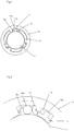
- a one-way clutch may include: a fixation part 11 provided at either an inner side or an outer side of a clutch part; an output part 12 provided at a position corresponding to the fixation part 11; an input part 13 provided between the fixation part 11 and the output part 12; and a forward key means 21 provided on the output part 12 to key-lock the output part 12 in the forward direction.
- a reverse key means 22 may be provided in an opposite direction to the forward key means 21 to key-lock the output part 12 in the reverse direction.
- a key means may include a key groove 20a formed in the output part 12 and gradually decreasing in depth along an opposite direction to the direction of rotation control, and a key 20b received in the key groove 20a and released from locking state by the unlocking operation of the input part 13.
- the key 20b may be provided in various shapes such as spherical, cylindrical or wedge shapes, which can provide a friction lock or a wedge lock between the fixation part 11 and the key groove 20a of the output part 12.
- the key means may include two key grooves 20a provided for the forward direction and reverse direction, respectively, and one key 20b provided between the two key grooves 20a.
- a release lever 23 may be provided to unlock the key 20b by pushing, by means of the input part 13, the key 20b between the key 20b of the key means and the input part 13.
- the release lever 23 has such a length that it 23 is not interfered with the fixation part 11 when the releasing lever 23 stands upright in the releasing operation.
- an elastic support 20c may be provided for elastically supporting the key 20b in the key groove 20a.
- the elastic support 20c may be formed as an elastic piece protruding from the key groove 20a.
- the elastic support 20c may be provided as a key 20b spring for elastically supporting the key 20b received in the key groove 20a.
- a driving projection 13a may protrude from the input part 13 toward the output part 12 and a protrusion restricting groove 12a may be formed on the corresponding output part 12 in a circumferential direction with a predetermined width, whereby the output part 12 can be stably driven by means of the input part 13.
- the one-way clutch described above including a fixation part 11 provided at either an inner side or an outer side of a clutch part; an output part 12 provided at a position corresponding to the fixation part 11; an input part 13 provided between the fixation part 11 and the output part 12; and a forward key means 21 provided on the output part 12 to key-lock the output part 12 in the forward direction, the rotation of the output part is key-locked in the forward direction by means of the forward key means and the key-locking of the forward key means is released by means of the input part such that the output part is rotated in the forward direction by means of the input part, while the output part is rotated in the reverse direction by means of the input part, and accordingly, the output part is rotated in the forward and reverse directions by means of the input part.
- the rotation of the output part 12 by means of the input part 13 can be rotationally driven in both directions.
- the release lever 23 when the release lever 23 is provided to unlock the key 20b by pushing, by means of the input part 13, the key 20b between the key 20b of the key means and the input part 13, the key 20b locked in the key groove 20a is smoothly released by means of the release lever 23, so that the operation is stably performed.
- the elastic support 20c for elastically supporting the key 20b when the elastic support 20c for elastically supporting the key 20b is provided in the key groove 20a, the key 20b is precisely constrained in the key groove 20a, and accordingly, the rotation of the output part 12 can be controlled precisely.
Landscapes
- Engineering & Computer Science (AREA)
- General Engineering & Computer Science (AREA)
- Mechanical Engineering (AREA)
- Braking Arrangements (AREA)
- Soil Working Implements (AREA)
- Lock And Its Accessories (AREA)
Applications Claiming Priority (2)
| Application Number | Priority Date | Filing Date | Title |
|---|---|---|---|
| KR1020150127671A KR101672650B1 (ko) | 2015-09-09 | 2015-09-09 | 양방향 회전이 가능한 원웨이 클러치 |
| PCT/KR2016/007264 WO2017043744A1 (ko) | 2015-09-09 | 2016-07-05 | 양방향 회전이 가능한 원웨이 클러치 |
Publications (2)
| Publication Number | Publication Date |
|---|---|
| EP3348853A1 true EP3348853A1 (de) | 2018-07-18 |
| EP3348853A4 EP3348853A4 (de) | 2019-04-03 |
Family
ID=57530062
Family Applications (1)
| Application Number | Title | Priority Date | Filing Date |
|---|---|---|---|
| EP16844564.1A Withdrawn EP3348853A4 (de) | 2015-09-09 | 2016-07-05 | Einwegkupplung mit bidirektionaler rotation |
Country Status (6)
| Country | Link |
|---|---|
| US (1) | US20180259010A1 (de) |
| EP (1) | EP3348853A4 (de) |
| JP (1) | JP6488060B2 (de) |
| KR (1) | KR101672650B1 (de) |
| CN (1) | CN107407351A (de) |
| WO (1) | WO2017043744A1 (de) |
Families Citing this family (8)
| Publication number | Priority date | Publication date | Assignee | Title |
|---|---|---|---|---|
| DE102016004031A1 (de) * | 2016-04-02 | 2017-10-05 | Borgwarner Inc. | Freilauf und Verfahren zur Herstellung eines solchen Freilaufs |
| KR102258482B1 (ko) | 2017-05-02 | 2021-05-31 | 현대자동차주식회사 | 커넥팅 로드 |
| CN108142963B (zh) * | 2018-01-05 | 2020-01-24 | 河南科丰种业集团有限公司 | 一种手动蘑菇挤压除水装置 |
| KR102052265B1 (ko) * | 2018-05-09 | 2019-12-04 | 대동모벨시스템 주식회사 | 차량용 사이드 스텝의 구동장치 |
| CN110465357B (zh) * | 2019-09-10 | 2021-02-26 | 王海潮 | 一种建筑工程用粉碎装置 |
| JP7663558B2 (ja) * | 2020-08-06 | 2025-04-16 | スガツネ工業株式会社 | 片方向制動ヒンジ |
| WO2022186510A1 (ko) * | 2021-03-04 | 2022-09-09 | 이엠티씨 주식회사 | 변속충격이 저감된 원심클러치와 이를 구비한 변속장치 |
| KR102402872B1 (ko) * | 2021-09-29 | 2022-05-30 | 이엠티씨 주식회사 | 변속충격이 저감된 원심클러치와 이를 구비한 변속장치 |
Family Cites Families (22)
| Publication number | Priority date | Publication date | Assignee | Title |
|---|---|---|---|---|
| US2408962A (en) * | 1945-05-23 | 1946-10-08 | Carl E Swenson | One-way clutch and bearing |
| DE1299956B (de) * | 1966-04-29 | 1969-07-24 | Ringspann Maurer Kg A | Kaefig fuer eine Freilaufkupplung mit Klemmstuecken |
| JPH0452630U (de) * | 1990-09-11 | 1992-05-06 | ||
| JP3584592B2 (ja) * | 1996-02-07 | 2004-11-04 | 株式会社デンソー | 一方向クラッチ |
| JPH1151092A (ja) * | 1997-06-02 | 1999-02-23 | Ichikoh Ind Ltd | 駆動機構 |
| JPH11257379A (ja) * | 1998-03-09 | 1999-09-21 | Ichikoh Ind Ltd | クラッチ機構 |
| JP3865350B2 (ja) * | 1999-01-21 | 2007-01-10 | 株式会社ジェイテクト | 両方向クラッチ |
| JP2003028201A (ja) * | 2001-07-13 | 2003-01-29 | Koyo Seiko Co Ltd | 一方向クラッチユニット |
| US7370741B2 (en) * | 2002-01-21 | 2008-05-13 | Nsk Ltd. | Engine start roller clutch-housed type rotation transmission device |
| JP4188143B2 (ja) * | 2002-06-03 | 2008-11-26 | 株式会社ユタカ技研 | 一方向クラッチ |
| JP4263587B2 (ja) * | 2003-12-08 | 2009-05-13 | 本田技研工業株式会社 | ワンウェイクラッチ装置及びこれを用いた自動二輪車 |
| JP4943786B2 (ja) * | 2005-11-15 | 2012-05-30 | Ntn株式会社 | 一方向クラッチユニット |
| US20070267263A1 (en) * | 2006-05-19 | 2007-11-22 | Jack Eric Pederson | Overrunning clutch |
| JP5274364B2 (ja) * | 2008-08-26 | 2013-08-28 | Nskワーナー株式会社 | ワンウェイクラッチ |
| JP2010242802A (ja) * | 2009-04-02 | 2010-10-28 | Ntn Corp | 逆入力遮断クラッチ |
| JP5307173B2 (ja) * | 2011-03-04 | 2013-10-02 | オリジン電気株式会社 | 双方向空転可能なワンウェイクラッチ |
| JP5717283B2 (ja) * | 2011-03-09 | 2015-05-13 | Ntn株式会社 | クラッチユニット |
| US8910764B2 (en) * | 2011-11-18 | 2014-12-16 | Pmg Indiana Corp. | Overrunning clutch with integral piloting using assembled bearing blocks |
| CN202402518U (zh) * | 2012-01-06 | 2012-08-29 | 三阳工业股份有限公司 | 单向离合器及配备该单向离合器的引擎 |
| JP6009898B2 (ja) * | 2012-10-11 | 2016-10-19 | Ntn株式会社 | クラッチおよびボールねじモジュール並びに装置類 |
| KR20140111569A (ko) | 2013-03-11 | 2014-09-19 | (주)테라솔라 | 양방향 클러치 어셈블리 및 이를 이용한 회전축 구동장치 |
| JP6176452B2 (ja) * | 2014-01-28 | 2017-08-09 | 本田技研工業株式会社 | ワンウェイクラッチおよびクランク式無段変速機 |
-
2015
- 2015-09-09 KR KR1020150127671A patent/KR101672650B1/ko not_active Expired - Fee Related
-
2016
- 2016-07-05 EP EP16844564.1A patent/EP3348853A4/de not_active Withdrawn
- 2016-07-05 CN CN201680009591.6A patent/CN107407351A/zh active Pending
- 2016-07-05 JP JP2018532019A patent/JP6488060B2/ja not_active Expired - Fee Related
- 2016-07-05 US US15/758,406 patent/US20180259010A1/en not_active Abandoned
- 2016-07-05 WO PCT/KR2016/007264 patent/WO2017043744A1/ko not_active Ceased
Also Published As
| Publication number | Publication date |
|---|---|
| JP2018530723A (ja) | 2018-10-18 |
| KR101672650B1 (ko) | 2016-11-04 |
| CN107407351A (zh) | 2017-11-28 |
| EP3348853A4 (de) | 2019-04-03 |
| US20180259010A1 (en) | 2018-09-13 |
| WO2017043744A1 (ko) | 2017-03-16 |
| JP6488060B2 (ja) | 2019-03-20 |
Similar Documents
| Publication | Publication Date | Title |
|---|---|---|
| US20180259010A1 (en) | One-way clutch capable of bi-directional rotation | |
| EP0118773B1 (de) | Stockförmige Handbremsvorrichtung für Fahrzeuge | |
| JP6371382B2 (ja) | 車両のオートマチックトランスミッションの操作要素をパーキングポジションへ変位させるための装置、このような装置を運転するための方法及び車両のオートマチックトランスミッションをシフトするためのシフト装置 | |
| US9248072B2 (en) | Fixing device for adjusting a telescoping arrangement | |
| US7735619B2 (en) | Control apparatus for vehicle and parking mechanism | |
| JP6461123B2 (ja) | 車両のオートマチックトランスミッションの操作要素をロックするための装置、このような装置を運転するための方法及び車両のオートマチックトランスミッションをシフトするためのシフト装置 | |
| CN101716976B (zh) | 自行车控制装置 | |
| EP0658475A1 (de) | Steuersystem für ein Arbeitgerät an einem Fahrrad | |
| CN108223613B (zh) | 低侧隙的多模式离合器 | |
| US20140116835A1 (en) | Vehicle park lock assembly | |
| US9017212B2 (en) | Wedge one-way clutch with gear thrust activation | |
| EP0482559A2 (de) | Verstärker für manuelle Betätigungskraft die an eine funktionnelle Vorrichtung eines Fahrrads übertragen wird | |
| SE530021C2 (sv) | Växelförare vid ett nav hos ett hjul med snabblåsningsfunktion och metod för att ändra utväxling mellan en drivanordning och ett hjul hos ett fordon | |
| EP2039572B1 (de) | Freigabemechanismus für eine Feststellbremsenkupplung | |
| US10788089B2 (en) | Speed differential device for a common double overrunning clutch | |
| JP2009523980A (ja) | プルタイプまたはプッシュタイプのキャリアの始動をアシストするためのシステム | |
| CN109687641B (zh) | 一种驱动电机离合的装置 | |
| JP2012031964A (ja) | 逆入力遮断クラッチ | |
| JPS604630A (ja) | クラツチ | |
| CN111692225B (zh) | 离合器装置及其保持器 | |
| US445118A (en) | Julius krieger and albert | |
| KR100716825B1 (ko) | 자동변속기 차량의 파킹장치 | |
| JP2017171011A (ja) | パーキング機構の制御装置 | |
| KR101360426B1 (ko) | 변속기용 롤러 클러치 | |
| KR20180115016A (ko) | 전자식 파킹 시스템 |
Legal Events
| Date | Code | Title | Description |
|---|---|---|---|
| STAA | Information on the status of an ep patent application or granted ep patent |
Free format text: STATUS: THE INTERNATIONAL PUBLICATION HAS BEEN MADE |
|
| PUAI | Public reference made under article 153(3) epc to a published international application that has entered the european phase |
Free format text: ORIGINAL CODE: 0009012 |
|
| STAA | Information on the status of an ep patent application or granted ep patent |
Free format text: STATUS: REQUEST FOR EXAMINATION WAS MADE |
|
| 17P | Request for examination filed |
Effective date: 20180404 |
|
| AK | Designated contracting states |
Kind code of ref document: A1 Designated state(s): AL AT BE BG CH CY CZ DE DK EE ES FI FR GB GR HR HU IE IS IT LI LT LU LV MC MK MT NL NO PL PT RO RS SE SI SK SM TR |
|
| AX | Request for extension of the european patent |
Extension state: BA ME |
|
| DAV | Request for validation of the european patent (deleted) | ||
| DAX | Request for extension of the european patent (deleted) | ||
| A4 | Supplementary search report drawn up and despatched |
Effective date: 20190304 |
|
| RIC1 | Information provided on ipc code assigned before grant |
Ipc: F16D 41/06 20060101AFI20190226BHEP Ipc: F16D 41/064 20060101ALI20190226BHEP |
|
| STAA | Information on the status of an ep patent application or granted ep patent |
Free format text: STATUS: THE APPLICATION IS DEEMED TO BE WITHDRAWN |
|
| 18D | Application deemed to be withdrawn |
Effective date: 20191001 |