EP3348719A1 - Dispositif d'actionnement pour une soupape d'un dispositif d'écoulement pour un bassin - Google Patents
Dispositif d'actionnement pour une soupape d'un dispositif d'écoulement pour un bassin Download PDFInfo
- Publication number
- EP3348719A1 EP3348719A1 EP18150623.9A EP18150623A EP3348719A1 EP 3348719 A1 EP3348719 A1 EP 3348719A1 EP 18150623 A EP18150623 A EP 18150623A EP 3348719 A1 EP3348719 A1 EP 3348719A1
- Authority
- EP
- European Patent Office
- Prior art keywords
- actuating
- guide
- latching
- actuator
- detent
- Prior art date
- Legal status (The legal status is an assumption and is not a legal conclusion. Google has not performed a legal analysis and makes no representation as to the accuracy of the status listed.)
- Granted
Links
- 238000006073 displacement reaction Methods 0.000 claims description 24
- 230000008878 coupling Effects 0.000 claims description 20
- 238000010168 coupling process Methods 0.000 claims description 20
- 238000005859 coupling reaction Methods 0.000 claims description 20
- 238000007789 sealing Methods 0.000 claims description 15
- 230000005540 biological transmission Effects 0.000 claims description 7
- 238000009423 ventilation Methods 0.000 claims description 2
- 238000013022 venting Methods 0.000 claims description 2
- 239000007788 liquid Substances 0.000 abstract description 6
- 238000009825 accumulation Methods 0.000 abstract description 3
- 230000035508 accumulation Effects 0.000 abstract description 3
- 238000004146 energy storage Methods 0.000 description 10
- 239000000463 material Substances 0.000 description 6
- 230000000295 complement effect Effects 0.000 description 4
- 230000004888 barrier function Effects 0.000 description 3
- 230000007704 transition Effects 0.000 description 3
- XLYOFNOQVPJJNP-UHFFFAOYSA-N water Substances O XLYOFNOQVPJJNP-UHFFFAOYSA-N 0.000 description 3
- 238000004026 adhesive bonding Methods 0.000 description 2
- 239000007769 metal material Substances 0.000 description 2
- 238000000034 method Methods 0.000 description 2
- 230000008569 process Effects 0.000 description 2
- 238000005299 abrasion Methods 0.000 description 1
- 230000009471 action Effects 0.000 description 1
- 230000006835 compression Effects 0.000 description 1
- 238000007906 compression Methods 0.000 description 1
- 230000007423 decrease Effects 0.000 description 1
- 230000001934 delay Effects 0.000 description 1
- 230000002349 favourable effect Effects 0.000 description 1
- 239000012530 fluid Substances 0.000 description 1
- 230000000149 penetrating effect Effects 0.000 description 1
- 230000002093 peripheral effect Effects 0.000 description 1
- 238000003825 pressing Methods 0.000 description 1
- 229910001220 stainless steel Inorganic materials 0.000 description 1
- 239000010935 stainless steel Substances 0.000 description 1
- 210000002105 tongue Anatomy 0.000 description 1
- 230000000007 visual effect Effects 0.000 description 1
Images


Classifications
-
- E—FIXED CONSTRUCTIONS
- E03—WATER SUPPLY; SEWERAGE
- E03C—DOMESTIC PLUMBING INSTALLATIONS FOR FRESH WATER OR WASTE WATER; SINKS
- E03C1/00—Domestic plumbing installations for fresh water or waste water; Sinks
- E03C1/12—Plumbing installations for waste water; Basins or fountains connected thereto; Sinks
- E03C1/22—Outlet devices mounted in basins, baths, or sinks
- E03C1/23—Outlet devices mounted in basins, baths, or sinks with mechanical closure mechanisms
- E03C1/2304—Outlet devices mounted in basins, baths, or sinks with mechanical closure mechanisms the actuation force being transmitted to the plug via flexible elements, e.g. chain, Bowden cable
-
- E—FIXED CONSTRUCTIONS
- E03—WATER SUPPLY; SEWERAGE
- E03C—DOMESTIC PLUMBING INSTALLATIONS FOR FRESH WATER OR WASTE WATER; SINKS
- E03C1/00—Domestic plumbing installations for fresh water or waste water; Sinks
- E03C1/12—Plumbing installations for waste water; Basins or fountains connected thereto; Sinks
- E03C1/22—Outlet devices mounted in basins, baths, or sinks
- E03C1/23—Outlet devices mounted in basins, baths, or sinks with mechanical closure mechanisms
- E03C2001/2317—Outlet devices mounted in basins, baths, or sinks with mechanical closure mechanisms transmission of actuation force involves a spring
Definitions
- the actuator is designed as a rotary eccentric, as a pull button or as a push button.
- the actuator In the operating devices with a trained as Drehexzenter or as a pull knob actuator, the actuator is in any operating state of the actuator to a large height of 10 mm or more on the top of a countertop or a sink on which the actuator is arranged over.
- An actuator with such a large height constitutes a barrier which must be overcome by lifting objects moving in the area of the sink, such as plates, pots or the like, which impairs the use of the sink for which the actuator is intended.
- the actuating element is designed as a push button
- the actuating element is in different operating states of the actuating device, which are associated with a closed position or an open position of the valve of the drain assembly, at different altitudes relative to the countertop or the sink, to which the actuator is mounted, arranged.
- the actuator is a considerable distance, for example, about 30 mm, over the top of the countertop or the sink, or is the actuator to a considerable distance, for example, 12 mm, relative to the top of the worktop or lowered the sink.
- the actuator forms a barrier which limits the use of the sink; in the second case, liquid and / or dirt may accumulate over the lowered actuator.
- the present invention has for its object to provide an actuator for opening and closing a valve of a drain assembly for a basin of the type mentioned, which affects neither the usability of the pool and its environment still favors accumulation of liquids and dirt.
- the actuating element is thus only briefly, during an actuation operation, by which the valve is transferred from the closed position to the open position or from the open position to the closed position, deflected from its rest position, while the actuating element between the actuation processes always at the same height is arranged relative to the guide.
- This height can be chosen so that the actuator in the rest position neither represents a barrier to be overcome in use of the basin nor favors the accumulation of liquids or dirt.
- the actuating device comprises a biasing device, by means of which the actuating element is biased in the rest position.
- Such a biasing device may in particular comprise a spring element, for example a compression spring element and / or a helical spring element.
- the spring element can in particular be supported on the one hand on the actuating element and on the other hand on the first locking element.
- the actuating element preferably has a stop, with which the actuating element rests in the rest position of the actuating element on a stop surface of the guide. This makes it possible in particular, the Adjusting the position of the top of the actuator relative to the position of the top of the guide in the rest position of the actuator precisely.
- the stop surface of the guide is preferably arranged transversely, in particular substantially perpendicular, to the direction of displacement of the actuating element, along which the actuating element is displaced from the rest position into the working position.
- the at least one air channel may also serve to drain the guide space to remove any liquid accumulated in the guide space therefrom.
- At least one air duct is arranged in a bottom wall of the guide space.
- the actuating element is guided against rotation on the guide. It is thus achieved, in particular, that any marking on the actuating element, for example a manufacturer's logo, a lettering or another symbol, maintains its orientation relative to the basin even during displacement of the actuating element relative to the guide.
- the actuating device preferably comprises a coupling element for coupling a force transmission element, in particular a Bowden cable, to the actuating device.
- a force transmission element in particular a Bowden cable
- the coupling element may be connected to the first latching element so that it shifts together with the first latching element, or provided directly on the first latching element, in particular integrally formed with the first latching element, be.
- the actuating device comprises a spring element for biasing the detent device in the first detent position and / or in the second detent position.
- the guide has a guide flange, with which the guide can be placed on the top of a countertop or a sink.
- the guide flange has a height of at most about 4 mm, preferably of at most about 3 mm, in particular of at most about 2 mm.
- the height of the guide flange is to be regarded as the extent along the displacement direction of the actuating element.
- the actuating element is provided with a sealing element for (preferably liquid-tight) sealing between the actuating element and the guide.
- the actuating device according to the invention is particularly suitable for use in a combination of a drainage arrangement for a basin, which comprises a valve for closing a basin drain and a drive device for driving a movement of the valve from a closed position to an open position, an actuating device according to the invention and a force transmission element, in particular a Bowden cable, for coupling the actuator and the drive device.
- the basin for which the drainage arrangement is provided is preferably a sink, in particular a sink of a kitchen sink.
- the actuator according to the invention can preferably be mounted on all sinks and countertops with conventional material thicknesses of, for example, up to 40 mm.
- the actuating device always has the same visual appearance on its upper side facing the operator, regardless of whether the latching device is in the first latching position or in the second latching position.
- the actuating element and / or the guide are preferably formed in the visible state in the assembled state of the operating device of the operator visible area of a metallic material, in particular of a stainless steel material. As a result, low abrasion values are achieved.
- the actuator may comprise an energy storage element, for example an energy storage spring, in which energy stored by the operator during an actuation process of the actuator is stored.
- an energy storage element for example an energy storage spring
- the energy storage element by utilizing the force exerted by the operator on the actuating element pressing force in the transfer of the locking device of the first Detent position is charged in the second detent position with elastic energy, which is then used to transfer the locking device of the second detent position in the first detent position.
- the first detent position is associated with a closed position of the valve of the drain assembly and the second detent position of an open position of the valve of the drain assembly.
- the actuator according to the invention can be used as a manual drain remote control for a drain assembly with a valve for closing a pool drain.
- the actuator according to the invention is basically usable with all eccentric drain fittings and can thus be exchanged for all existing remote controls.
- the actuating device according to the invention thus has a high versatility.
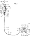
- the Fig. 1 and 2 show a combination of a drain assembly 102 for a basin (not shown), particularly for a sink of a kitchen sink, which includes a valve 104 for closing a pool outlet of the basin and a drive device 106 for driving a movement of the valve 104 of it in Fig. 1 illustrated closed position in his in Fig. 2 illustrated open position, an actuator 108 for triggering an opening movement and a closing movement of the valve 104 of the drain assembly 102 and a power transmission element 110, for example in the form of a Bowden cable 111, for coupling the actuator 108 and the drive device 106 of the drain assembly 102 to a driving force to open or closing the valve 104 from the actuator 108 to the drive device 106.
- the drain assembly 102 includes a cup 112 which is fixed to the bottom of the basin or formed integrally with the bottom of the basin.
- the cup 112 has a drain opening 114, which in the in Fig. 1 shown closed position of the valve 104 is closed by a sealing plug 118, which sealingly sealingly abuts a sealing element 116 surrounding the drain opening 114 bottom portion of the cup 112 via a sealing element.
- pivot axis 126 is pivotally mounted on a main body 128 of the drain assembly 102.
- the lift finger 124 is rotatably connected to a pivot arm 130, which in turn is in engagement with a drain assembly end portion 132 of a wire 134 of the Bowden cable 111.
- the Bowden cable 111 further comprises a sheath 136, which serves as a mechanical guide of the wire rope 134 and as an abutment for the tensile and compressive forces transmitted via the cable 134.
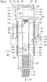
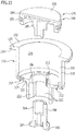
- An operating device side end portion 138 of the wire 134 is in the assembled state of the combination 100 in one example in the Fig. 8 and 9 shown receptacle 140 of a coupling element 142 of the actuator 108 is inserted and secured in the same by means provided on the sleeve 136 threaded sleeve 144.
- an internal thread of the threaded sleeve 144 engages in a complementary external thread 146 of a lower end portion 148 of the actuator 108 a.
- Fig. 1 For example, the actuator side end portion 138 of the wire 134 is shown detached from the coupling member 142.
- Fig. 2 For example, the actuator-side end portion 138 is inserted into the receptacle 140 of the coupling member 142, but not yet secured by the bushing sleeve 144 therein. During operation of the combination 100, however, the operating device-side end region 138 of the wire rope 134 is always coupled to the coupling element 142 and secured thereto.
- a further screw sleeve 150 is provided which, preferably also by screwing, is fixed to the drain assembly 102.
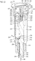
- the lower end portion 148 of the actuator 108 preferably by latching, on a housing 152 of a designated as a whole 154 locking device of the actuator 108 is fixed.
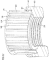
- the housing 152 of the latching device 154 is formed substantially hollow cylindrical and preferably has an external thread 156 which engages with a complementary internal thread 158 of a screwed onto the housing 152 retaining nut 160 is engaged.
- the retaining nut 160 carries a sliding ring 162 surrounding the housing 152, the lower end of which preferably engages in a ring receptacle 164 of the retaining nut 160, which is bounded radially outward by an annular guide wall 166 of the retaining nut 160 (see in particular also FIG Fig. 12 ).
- the slip ring 162 may include a plurality of radially inwardly extending lands 168 that allow the slip ring 162 to be supported on the outside of the housing 152.
- the slip ring 162 cooperates with a guide flange 170 of a guide 172, generally designated 172, for releasably securing the actuator 108 to a countertop or sink (not shown).
- the actuator 108 is inserted into a (preferably substantially circular) passage opening of the worktop or the sink until the guide flange 170 rests with its bottom 174 on the top of the countertop or the sink.
- the retaining nut 160 which carries the slide ring 162, screwed on the external thread 156 of the housing 152 so far up until the top 176 of the slide ring 162 rests against the underside of the countertop or the sink, so that the worktop or the sink between the guide flange 170 and the slide ring 162 is clamped.
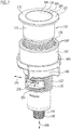
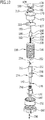
- the guide 172 of the actuator 108 is used, an actuating element 178 of the actuator 108, for example in the form of an actuating knob 180, during a linear displacement of the actuating element 178 from an example in Fig. 13 illustrated rest position in a in Fig. 14 shown working position - preferably in the vertical direction - to guide slidably.
- the guide 172 is formed for example in the form of a cylindrical pot, the interior of which receives the actuating element 178.
- the guide flange 170 may be provided on its underside 174 with a - preferably annular - sealing element 177.
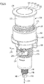
- the actuating element 178 is preferably designed in several parts.
- the actuating element 178 may comprise a visible-side actuating element upper part 184 facing an operator of the actuating device 108, an abutment part 186 delimiting the displacement path of the actuating element 178, and an actuating element lower part 188 arranged between the abutment part 186 and the actuating element upper part 184.
- the stop member 186 can by means of a screw 190 which passes through a running in the axial direction of the stop member 186 channel and is screwed into a threaded blind hole of the actuator lower part 188, releasably secured to the actuator lower part 188.
- the upper part of the actuating element 184 can be fixed to the lower part of the actuating element 188 in any suitable manner, in particular as a material fit, for example by gluing, and / or in a form-fitting manner, for example by latching.
- the actuating element upper part 184 is made of a different material from the actuating element lower part 188.
- the actuator top 184 may be formed of a metallic material while the actuator bottom 188 is formed of a plastic material.
- the stop member 186 has a stop 192, for example in the form of a radially outwardly projecting stop collar 194, with which the stop member 186 abuts a transversely, preferably substantially perpendicular, to the displacement direction 196 of the actuating member 178 aligned stop surface 198 of the guide 172 when the actuator 178 is in the rest position.
- the top 200 of the actuator 178 is preferably substantially flush with the top 202 of the guide flange 170 of the guide 172.
- the height of the upper side 202 of the guide flange 170, around which the guide flange 170 in the assembled state of the actuator 108 projects above the top of the worktop or the sink is preferably at most about 4 mm, in particular at most about 3 mm, particularly preferably at most about 2 mm.
- the stop member 186 further comprises a projecting from the shaft 204 in the radially outward and in the axial direction of the actuating element 178 extending projection 208 which engages in a complementary thereto (not shown) guide groove on the guide stub 206, so that the actuating element 178 is guided against rotation on the guide 172.
- a label optionally present on the upper side 200 of the actuating element upper part 184 for example a manufacturer logo, always retains the same orientation relative to the work surface or relative to the sink on which the actuating device 108 is arranged.
- the guide 172 and the actuator 178 together include a guide space 210 whose volume is maximum when the actuator 178 is in the example in Fig. 13 illustrated rest position, and decreases when the actuator 178 from the rest position in the in Fig. 14 shown work item is moved.
- the guide 172 has one or more, for example four, air channels 212 extending from an inner boundary wall surface of the guide 172 to an outer boundary wall surface of the guide 172.
- the air ducts 212 can also serve for dewatering the guide space 210 in order to allow any water penetrating from the top of the worktop or sink into the guide space 210 to flow out of the guide space 210 into the exterior space of the actuator 108.
- the guide 172 can basically be formed in one piece or in several parts.
- the guide upper part 216 and the guide lower part 220 can be fixed to each other in any suitable manner, in particular by material bonding, for example by adhesive bonding, and / or in a form-fitting manner, for example by latching.
- the guide 172 may further, preferably arranged on the guide base 220, locking tongues 222, by means of which the guide 172 with the housing 152 of the locking device 154 of the actuator 108 can be latched.
- the actuator 108 To bias the actuator 178 to the rest position, the actuator 108 includes a biasing device 224, which preferably includes a spring element 226 in the form of a coil spring 228.
- the spring element 226 is supported on the one hand on the actuating element 178 and on the other hand on a in the housing 152 of the locking device 154 in the direction of displacement 196 slidably guided first locking element 230 from.
- a first end of the spring element 226 is received in a receiving groove 232 of the actuating element 178 and / or a second end of the spring element 226 is received in a receiving space 234 of the first locking element 230.
- the first latching element 230 is preferably rigidly connected to the coupling element 142 of the actuator 108 or, as in the illustrated embodiment, formed integrally with the coupling element 142.
- the first latching element 230 is engaged with a second latching element 236, which is held displaceably in a guide groove 238 of the housing 152 of the latching device 154 in a guide direction 240, preferably aligned substantially perpendicular to the displacement direction 196 of the actuating element 178 and the first latching element 230.
- FIG. 3 and 4 How best of the Fig. 3 and 4 can be seen engages a radially inwardly projecting locking pin 242 of the second locking element 236 in a provided on the circumference of the first locking element 230 closed guideway 244 a.
- the latching pin 242 is in a first latching position, in which the first latching element 230 is deflected relative to the second latching element 236 at a maximum upward to the actuating element 178.
- the latching pin 242 is in a second latching position, in which the first latching element 230 is deflected relative to the second latching element 236 at a maximum downward, away from the actuating element 178.
- the generally approximately heart-shaped guide track 244 comprises a first guide track section 246a through which the second detent element 236 moves relative to the first detent element 230 from the first detent position to the second detent position when the first detent element 230 moves downwardly during a downward movement of the actuator 178 becomes.
- the guideway 244 includes a second guideway portion 246b, through which the second detent element 236 moves back relative to the first detent element 230 from the second detent position to the first detent position when the first detent element 230 is moved upward.
- This upward movement of the first latching element 230 is driven by an energy storage spring 248 which is supported on the one hand on the lower end portion 148 of the actuating device 108 and on the other hand on an annular collar 250 of the first latching element 230 (see, for example Fig. 9 ).
- the first locking element 230 is not rotationally symmetrical, but in particular provided with two protruding in the radial direction projections 252, which extend in the direction of displacement 196 and engage in complementary thereto guide grooves on the inside of the housing 152 of the locking device 154, whereby the first locking element 230 is guided against rotation on the housing 152.
- the movement of the second latching element 236 relative to the first latching element 230 through the guideway sections 246a, 246b along the circumferential direction of the first latching element 230 is made possible in the transition from the first latching position to the second latching position and back to the first latching position in that the second latching element 236 in the guide direction 240 is held displaceably on the housing 152 of the latching device 154, so that the second latching element 236 can move along the guide direction 240 during the transition between the two latching positions.
- the latching device 154 of the actuating device 108 is in its first detent position in which the first latching element 230 is displaced maximally upwards relative to the second latching element 236.
- the first locking element 230 is biased by the energy storage spring 248 against the second locking element 236 in this first detent position.
- the spring element 226 of the biasing device 224 biases the actuator 178 in its rest position, in which the stop 192 of the actuator 178 abuts the stop surface 198 of the guide 172 and the top 200 of the actuator 178 is substantially flush with the top 202 of the guide 172.
- the actuator 178 is thereby moved relative to the guide 172 down to a working position.
- the spring element 226 is compressed, and the lower end of the actuating element 178 comes into contact with the upper end of the first latching element 230, whereby the first latching element 230 is pressed against the restoring force of the energy storage spring 248 down.
- the latching pin 242 of the second latching element 136 comes out of the in Fig. 3 shown first detent position and by the first guide track portion 246a of the guide rail 244 on the first locking element 230 to the in Fig. 4 illustrated second detent position, in which the locking pin 242 prevents further downward movement of the first locking element 230.
- the coupling element 142 also moves downward at the lower end of the first latching element 230 together with the actuating device-side end region 138 of the wire cable 134 of the Bowden cable 111 in the direction of displacement 196.
- the coupling element 142 is completely received in the lower end portion 148 of the actuator 108 when the locking device 154 is in the first detent position, and that the coupling element 142 with the receptacle 140 for the actuator side end portion 138 of the wire 134 down projects beyond the lower end portion 148 of the actuator 108 when the latch 154 is in the second detent position.
- the actuator 178 returns under the action of the restoring force of the spring element 226 of the biasing device 224 in the Fig. 15 shown rest position in which the top 200 of the actuating element 178 with the top 202 of the guide 172 is substantially flush.
- the top of the actuating device 108 thus always has the same appearance for the operator between the actuating operations, regardless of whether the locking device 154 of the actuating device 108 is in the first detent position or in the second detent position.
- the latching pin 242 of the second latching element 236 is released from the second latching position, and the first latching element 230 is moved back under relaxation of the energy storage spring 248, when utilizing the elastic energy stored therein in the first latching position, wherein the latching pin 242, the second guide track section 246b of the guideway 244 passes through the first locking element 230 until it returns to the in Fig. 3 achieved shown first latching position in which the locking pin 242 prevents further upward movement of the first locking element 230.
- the actuator 178 as soon as the operator no longer exerts pressure on the top 200 of the actuating element 178, by the restoring force of the spring element 226 of the biasing device 224 in the in Fig. 13 shown rest position in which the top 200 of the actuating element 178 is substantially flush with the top 202 of the guide 172.
Landscapes
- Engineering & Computer Science (AREA)
- Mechanical Engineering (AREA)
- Environmental & Geological Engineering (AREA)
- Health & Medical Sciences (AREA)
- Life Sciences & Earth Sciences (AREA)
- Hydrology & Water Resources (AREA)
- Public Health (AREA)
- Water Supply & Treatment (AREA)
- Sink And Installation For Waste Water (AREA)
- Mechanically-Actuated Valves (AREA)
Applications Claiming Priority (1)
| Application Number | Priority Date | Filing Date | Title |
|---|---|---|---|
| DE102017100533.1A DE102017100533A1 (de) | 2017-01-12 | 2017-01-12 | Betätigungsvorrichtung für ein Ventil einer Ablaufanordnung für ein Becken |
Publications (2)
| Publication Number | Publication Date |
|---|---|
| EP3348719A1 true EP3348719A1 (fr) | 2018-07-18 |
| EP3348719B1 EP3348719B1 (fr) | 2020-09-23 |
Family
ID=60953692
Family Applications (1)
| Application Number | Title | Priority Date | Filing Date |
|---|---|---|---|
| EP18150623.9A Active EP3348719B1 (fr) | 2017-01-12 | 2018-01-08 | Dispositif d'actionnement pour une soupape d'un dispositif d'écoulement pour un bassin |
Country Status (3)
| Country | Link |
|---|---|
| EP (1) | EP3348719B1 (fr) |
| DE (1) | DE102017100533A1 (fr) |
| ES (1) | ES2836434T3 (fr) |
Cited By (1)
| Publication number | Priority date | Publication date | Assignee | Title |
|---|---|---|---|---|
| DE102022209842A1 (de) | 2022-09-19 | 2024-03-21 | Blanco Gmbh + Co Kg | Betätigungsvorrichtung zum Öffnen oder Schließen eines Ventils einer Ablaufanordnung sowie Ablaufsystem |
Citations (3)
| Publication number | Priority date | Publication date | Assignee | Title |
|---|---|---|---|---|
| US3220695A (en) * | 1965-04-30 | 1965-11-30 | Sterling Faucet Company | Push-button drain valve |
| AT317097B (de) * | 1971-10-18 | 1974-08-12 | Hutterer & Lechner Kg | Vorrichtung zum Öffnen und Schließen eines Verschlusses, insbesondere des Verschlußstopfens von Badewannen, Waschmuscheln u.dgl. |
| EP1870527A1 (fr) * | 2006-06-20 | 2007-12-26 | Geberit Technik Ag | Dispositif pour activer le clapet d'écoulement d'articles sanitaires. |
Family Cites Families (2)
| Publication number | Priority date | Publication date | Assignee | Title |
|---|---|---|---|---|
| JP3344076B2 (ja) * | 1994-05-24 | 2002-11-11 | 株式会社ノーリツ | 排水栓装置 |
| JP6019280B2 (ja) * | 2011-05-31 | 2016-11-02 | 丸一株式会社 | 遠隔操作式排水栓装置及び遠隔操作式排水栓装置の位置決め治具 |
-
2017
- 2017-01-12 DE DE102017100533.1A patent/DE102017100533A1/de active Pending
-
2018
- 2018-01-08 EP EP18150623.9A patent/EP3348719B1/fr active Active
- 2018-01-08 ES ES18150623T patent/ES2836434T3/es active Active
Patent Citations (3)
| Publication number | Priority date | Publication date | Assignee | Title |
|---|---|---|---|---|
| US3220695A (en) * | 1965-04-30 | 1965-11-30 | Sterling Faucet Company | Push-button drain valve |
| AT317097B (de) * | 1971-10-18 | 1974-08-12 | Hutterer & Lechner Kg | Vorrichtung zum Öffnen und Schließen eines Verschlusses, insbesondere des Verschlußstopfens von Badewannen, Waschmuscheln u.dgl. |
| EP1870527A1 (fr) * | 2006-06-20 | 2007-12-26 | Geberit Technik Ag | Dispositif pour activer le clapet d'écoulement d'articles sanitaires. |
Cited By (2)
| Publication number | Priority date | Publication date | Assignee | Title |
|---|---|---|---|---|
| DE102022209842A1 (de) | 2022-09-19 | 2024-03-21 | Blanco Gmbh + Co Kg | Betätigungsvorrichtung zum Öffnen oder Schließen eines Ventils einer Ablaufanordnung sowie Ablaufsystem |
| EP4350091A1 (fr) | 2022-09-19 | 2024-04-10 | BLANCO GmbH + Co KG | Dispositif d'actionnement pour ouvrir ou fermer une soupape d'un ensemble d'écoulement et système d'écoulement |
Also Published As
| Publication number | Publication date |
|---|---|
| EP3348719B1 (fr) | 2020-09-23 |
| ES2836434T3 (es) | 2021-06-25 |
| DE102017100533A1 (de) | 2018-07-12 |
Similar Documents
| Publication | Publication Date | Title |
|---|---|---|
| EP3420258B2 (fr) | Dispositif d'actionnement de soupape | |
| EP1703027B1 (fr) | Dispositif pour activer le clapet d'écoulement d'articles sanitaires et en particulier une baignoire | |
| DE202008005755U1 (de) | Frischhalte-Vakuum-Abdeckvorrichtung | |
| EP2413740B2 (fr) | Dispositif d'escamotage | |
| DE8333674U1 (de) | Kanne für Flüssigkeiten, insbesondere Isolierkanne | |
| DE102012025223A1 (de) | Unterdusche | |
| EP2998622A1 (fr) | Cartouche de soupape pour une armature sanitaire | |
| WO2018153655A1 (fr) | Partie supérieure de soupape | |
| EP2154320A2 (fr) | Arrêt de porte | |
| EP3348719B1 (fr) | Dispositif d'actionnement pour une soupape d'un dispositif d'écoulement pour un bassin | |
| EP4054903A1 (fr) | Dispositif adaptateur de balai d'essuie-glace, balai d'essuie-glace comprenant le dispositif adaptateur de balai d'essuie-glace, et essuie-glace comprenant le balai d'essuie-glace | |
| DE102014019290B4 (de) | Spülvorrichtung, insbesondere Toilettenspülung | |
| EP3348718B1 (fr) | Dispositif d'actionnement pour une soupape d'un dispositif d'écoulement pour un bassin | |
| EP0733749B1 (fr) | Dispositif d'actionnement pour un orifice de vidange d'un réservoir de chasse d'eau | |
| DE102011052811A1 (de) | Knauf-Zylinder mit druckknopfbetätigbarer Kupplung | |
| DE202014100217U1 (de) | Gargerät | |
| DE102008018894B3 (de) | Pneumatisches Handumreifungsgerät | |
| CH708555B1 (de) | Bodenfläche mit Bodenablauf, insbesondere einer Küchenspüle. | |
| DE102008028610B4 (de) | Fluidventil mit Zeitgeber | |
| DE2625601A1 (de) | Betaetigungsvorrichtung fuer den rueckstauverschluss eines kellerablaufs oder fuer dergleichen versenkt eingebauter absperrorgane | |
| EP3467215A1 (fr) | Raccord fileté d'évacuation | |
| DE10162819B4 (de) | Hydraulisches Steuerventil | |
| EP4350091A1 (fr) | Dispositif d'actionnement pour ouvrir ou fermer une soupape d'un ensemble d'écoulement et système d'écoulement | |
| DE4141172B4 (de) | Vorrichtung zum Umstellen eines Ventilgliedes an einer Sanitärarmatur | |
| DE202015101739U1 (de) | Küchenspülen-Anordnung |
Legal Events
| Date | Code | Title | Description |
|---|---|---|---|
| PUAI | Public reference made under article 153(3) epc to a published international application that has entered the european phase |
Free format text: ORIGINAL CODE: 0009012 |
|
| STAA | Information on the status of an ep patent application or granted ep patent |
Free format text: STATUS: THE APPLICATION HAS BEEN PUBLISHED |
|
| AK | Designated contracting states |
Kind code of ref document: A1 Designated state(s): AL AT BE BG CH CY CZ DE DK EE ES FI FR GB GR HR HU IE IS IT LI LT LU LV MC MK MT NL NO PL PT RO RS SE SI SK SM TR |
|
| AX | Request for extension of the european patent |
Extension state: BA ME |
|
| STAA | Information on the status of an ep patent application or granted ep patent |
Free format text: STATUS: REQUEST FOR EXAMINATION WAS MADE |
|
| 17P | Request for examination filed |
Effective date: 20190117 |
|
| RBV | Designated contracting states (corrected) |
Designated state(s): AL AT BE BG CH CY CZ DE DK EE ES FI FR GB GR HR HU IE IS IT LI LT LU LV MC MK MT NL NO PL PT RO RS SE SI SK SM TR |
|
| GRAP | Despatch of communication of intention to grant a patent |
Free format text: ORIGINAL CODE: EPIDOSNIGR1 |
|
| STAA | Information on the status of an ep patent application or granted ep patent |
Free format text: STATUS: GRANT OF PATENT IS INTENDED |
|
| INTG | Intention to grant announced |
Effective date: 20200512 |
|
| GRAS | Grant fee paid |
Free format text: ORIGINAL CODE: EPIDOSNIGR3 |
|
| GRAA | (expected) grant |
Free format text: ORIGINAL CODE: 0009210 |
|
| STAA | Information on the status of an ep patent application or granted ep patent |
Free format text: STATUS: THE PATENT HAS BEEN GRANTED |
|
| AK | Designated contracting states |
Kind code of ref document: B1 Designated state(s): AL AT BE BG CH CY CZ DE DK EE ES FI FR GB GR HR HU IE IS IT LI LT LU LV MC MK MT NL NO PL PT RO RS SE SI SK SM TR |
|
| REG | Reference to a national code |
Ref country code: GB Ref legal event code: FG4D Free format text: NOT ENGLISH |
|
| REG | Reference to a national code |
Ref country code: CH Ref legal event code: EP |
|
| REG | Reference to a national code |
Ref country code: IE Ref legal event code: FG4D Free format text: LANGUAGE OF EP DOCUMENT: GERMAN |
|
| REG | Reference to a national code |
Ref country code: AT Ref legal event code: REF Ref document number: 1316504 Country of ref document: AT Kind code of ref document: T Effective date: 20201015 Ref country code: DE Ref legal event code: R096 Ref document number: 502018002499 Country of ref document: DE |
|
| PG25 | Lapsed in a contracting state [announced via postgrant information from national office to epo] |
Ref country code: SE Free format text: LAPSE BECAUSE OF FAILURE TO SUBMIT A TRANSLATION OF THE DESCRIPTION OR TO PAY THE FEE WITHIN THE PRESCRIBED TIME-LIMIT Effective date: 20200923 Ref country code: FI Free format text: LAPSE BECAUSE OF FAILURE TO SUBMIT A TRANSLATION OF THE DESCRIPTION OR TO PAY THE FEE WITHIN THE PRESCRIBED TIME-LIMIT Effective date: 20200923 Ref country code: NO Free format text: LAPSE BECAUSE OF FAILURE TO SUBMIT A TRANSLATION OF THE DESCRIPTION OR TO PAY THE FEE WITHIN THE PRESCRIBED TIME-LIMIT Effective date: 20201223 Ref country code: GR Free format text: LAPSE BECAUSE OF FAILURE TO SUBMIT A TRANSLATION OF THE DESCRIPTION OR TO PAY THE FEE WITHIN THE PRESCRIBED TIME-LIMIT Effective date: 20201224 Ref country code: HR Free format text: LAPSE BECAUSE OF FAILURE TO SUBMIT A TRANSLATION OF THE DESCRIPTION OR TO PAY THE FEE WITHIN THE PRESCRIBED TIME-LIMIT Effective date: 20200923 Ref country code: BG Free format text: LAPSE BECAUSE OF FAILURE TO SUBMIT A TRANSLATION OF THE DESCRIPTION OR TO PAY THE FEE WITHIN THE PRESCRIBED TIME-LIMIT Effective date: 20201223 |
|
| PG25 | Lapsed in a contracting state [announced via postgrant information from national office to epo] |
Ref country code: LV Free format text: LAPSE BECAUSE OF FAILURE TO SUBMIT A TRANSLATION OF THE DESCRIPTION OR TO PAY THE FEE WITHIN THE PRESCRIBED TIME-LIMIT Effective date: 20200923 Ref country code: RS Free format text: LAPSE BECAUSE OF FAILURE TO SUBMIT A TRANSLATION OF THE DESCRIPTION OR TO PAY THE FEE WITHIN THE PRESCRIBED TIME-LIMIT Effective date: 20200923 |
|
| REG | Reference to a national code |
Ref country code: NL Ref legal event code: MP Effective date: 20200923 |
|
| REG | Reference to a national code |
Ref country code: LT Ref legal event code: MG4D |
|
| PG25 | Lapsed in a contracting state [announced via postgrant information from national office to epo] |
Ref country code: LT Free format text: LAPSE BECAUSE OF FAILURE TO SUBMIT A TRANSLATION OF THE DESCRIPTION OR TO PAY THE FEE WITHIN THE PRESCRIBED TIME-LIMIT Effective date: 20200923 Ref country code: SM Free format text: LAPSE BECAUSE OF FAILURE TO SUBMIT A TRANSLATION OF THE DESCRIPTION OR TO PAY THE FEE WITHIN THE PRESCRIBED TIME-LIMIT Effective date: 20200923 Ref country code: RO Free format text: LAPSE BECAUSE OF FAILURE TO SUBMIT A TRANSLATION OF THE DESCRIPTION OR TO PAY THE FEE WITHIN THE PRESCRIBED TIME-LIMIT Effective date: 20200923 Ref country code: PT Free format text: LAPSE BECAUSE OF FAILURE TO SUBMIT A TRANSLATION OF THE DESCRIPTION OR TO PAY THE FEE WITHIN THE PRESCRIBED TIME-LIMIT Effective date: 20210125 Ref country code: CZ Free format text: LAPSE BECAUSE OF FAILURE TO SUBMIT A TRANSLATION OF THE DESCRIPTION OR TO PAY THE FEE WITHIN THE PRESCRIBED TIME-LIMIT Effective date: 20200923 Ref country code: EE Free format text: LAPSE BECAUSE OF FAILURE TO SUBMIT A TRANSLATION OF THE DESCRIPTION OR TO PAY THE FEE WITHIN THE PRESCRIBED TIME-LIMIT Effective date: 20200923 |
|
| PG25 | Lapsed in a contracting state [announced via postgrant information from national office to epo] |
Ref country code: AL Free format text: LAPSE BECAUSE OF FAILURE TO SUBMIT A TRANSLATION OF THE DESCRIPTION OR TO PAY THE FEE WITHIN THE PRESCRIBED TIME-LIMIT Effective date: 20200923 Ref country code: IS Free format text: LAPSE BECAUSE OF FAILURE TO SUBMIT A TRANSLATION OF THE DESCRIPTION OR TO PAY THE FEE WITHIN THE PRESCRIBED TIME-LIMIT Effective date: 20210123 Ref country code: PL Free format text: LAPSE BECAUSE OF FAILURE TO SUBMIT A TRANSLATION OF THE DESCRIPTION OR TO PAY THE FEE WITHIN THE PRESCRIBED TIME-LIMIT Effective date: 20200923 |
|
| REG | Reference to a national code |
Ref country code: DE Ref legal event code: R097 Ref document number: 502018002499 Country of ref document: DE |
|
| REG | Reference to a national code |
Ref country code: ES Ref legal event code: FG2A Ref document number: 2836434 Country of ref document: ES Kind code of ref document: T3 Effective date: 20210625 |
|
| PG25 | Lapsed in a contracting state [announced via postgrant information from national office to epo] |
Ref country code: SK Free format text: LAPSE BECAUSE OF FAILURE TO SUBMIT A TRANSLATION OF THE DESCRIPTION OR TO PAY THE FEE WITHIN THE PRESCRIBED TIME-LIMIT Effective date: 20200923 |
|
| PLBE | No opposition filed within time limit |
Free format text: ORIGINAL CODE: 0009261 |
|
| STAA | Information on the status of an ep patent application or granted ep patent |
Free format text: STATUS: NO OPPOSITION FILED WITHIN TIME LIMIT |
|
| PG25 | Lapsed in a contracting state [announced via postgrant information from national office to epo] |
Ref country code: DK Free format text: LAPSE BECAUSE OF FAILURE TO SUBMIT A TRANSLATION OF THE DESCRIPTION OR TO PAY THE FEE WITHIN THE PRESCRIBED TIME-LIMIT Effective date: 20200923 Ref country code: SI Free format text: LAPSE BECAUSE OF FAILURE TO SUBMIT A TRANSLATION OF THE DESCRIPTION OR TO PAY THE FEE WITHIN THE PRESCRIBED TIME-LIMIT Effective date: 20200923 Ref country code: MC Free format text: LAPSE BECAUSE OF FAILURE TO SUBMIT A TRANSLATION OF THE DESCRIPTION OR TO PAY THE FEE WITHIN THE PRESCRIBED TIME-LIMIT Effective date: 20200923 |
|
| REG | Reference to a national code |
Ref country code: CH Ref legal event code: PL |
|
| 26N | No opposition filed |
Effective date: 20210624 |
|
| PG25 | Lapsed in a contracting state [announced via postgrant information from national office to epo] |
Ref country code: LU Free format text: LAPSE BECAUSE OF NON-PAYMENT OF DUE FEES Effective date: 20210108 |
|
| REG | Reference to a national code |
Ref country code: BE Ref legal event code: MM Effective date: 20210131 |
|
| PG25 | Lapsed in a contracting state [announced via postgrant information from national office to epo] |
Ref country code: CH Free format text: LAPSE BECAUSE OF NON-PAYMENT OF DUE FEES Effective date: 20210131 Ref country code: LI Free format text: LAPSE BECAUSE OF NON-PAYMENT OF DUE FEES Effective date: 20210131 |
|
| PG25 | Lapsed in a contracting state [announced via postgrant information from national office to epo] |
Ref country code: IE Free format text: LAPSE BECAUSE OF NON-PAYMENT OF DUE FEES Effective date: 20210108 |
|
| PG25 | Lapsed in a contracting state [announced via postgrant information from national office to epo] |
Ref country code: BE Free format text: LAPSE BECAUSE OF NON-PAYMENT OF DUE FEES Effective date: 20210131 |
|
| PGFP | Annual fee paid to national office [announced via postgrant information from national office to epo] |
Ref country code: IT Payment date: 20221213 Year of fee payment: 6 |
|
| PG25 | Lapsed in a contracting state [announced via postgrant information from national office to epo] |
Ref country code: NL Free format text: LAPSE BECAUSE OF NON-PAYMENT OF DUE FEES Effective date: 20200923 Ref country code: CY Free format text: LAPSE BECAUSE OF FAILURE TO SUBMIT A TRANSLATION OF THE DESCRIPTION OR TO PAY THE FEE WITHIN THE PRESCRIBED TIME-LIMIT Effective date: 20200923 |
|
| PG25 | Lapsed in a contracting state [announced via postgrant information from national office to epo] |
Ref country code: HU Free format text: LAPSE BECAUSE OF FAILURE TO SUBMIT A TRANSLATION OF THE DESCRIPTION OR TO PAY THE FEE WITHIN THE PRESCRIBED TIME-LIMIT; INVALID AB INITIO Effective date: 20180108 |
|
| PGFP | Annual fee paid to national office [announced via postgrant information from national office to epo] |
Ref country code: GB Payment date: 20231116 Year of fee payment: 7 |
|
| PGFP | Annual fee paid to national office [announced via postgrant information from national office to epo] |
Ref country code: FR Payment date: 20231108 Year of fee payment: 7 |
|
| REG | Reference to a national code |
Ref country code: AT Ref legal event code: MM01 Ref document number: 1316504 Country of ref document: AT Kind code of ref document: T Effective date: 20230108 |
|
| PGFP | Annual fee paid to national office [announced via postgrant information from national office to epo] |
Ref country code: ES Payment date: 20240206 Year of fee payment: 7 |
|
| PG25 | Lapsed in a contracting state [announced via postgrant information from national office to epo] |
Ref country code: AT Free format text: LAPSE BECAUSE OF NON-PAYMENT OF DUE FEES Effective date: 20230108 |
|
| PG25 | Lapsed in a contracting state [announced via postgrant information from national office to epo] |
Ref country code: MK Free format text: LAPSE BECAUSE OF FAILURE TO SUBMIT A TRANSLATION OF THE DESCRIPTION OR TO PAY THE FEE WITHIN THE PRESCRIBED TIME-LIMIT Effective date: 20200923 Ref country code: AT Free format text: LAPSE BECAUSE OF NON-PAYMENT OF DUE FEES Effective date: 20230108 |
|
| PGFP | Annual fee paid to national office [announced via postgrant information from national office to epo] |
Ref country code: DE Payment date: 20240124 Year of fee payment: 7 |