EP3348503A2 - Blattbearbeitungsvorrichtung und blattbearbeitungsverfahren - Google Patents
Blattbearbeitungsvorrichtung und blattbearbeitungsverfahren Download PDFInfo
- Publication number
- EP3348503A2 EP3348503A2 EP17208458.4A EP17208458A EP3348503A2 EP 3348503 A2 EP3348503 A2 EP 3348503A2 EP 17208458 A EP17208458 A EP 17208458A EP 3348503 A2 EP3348503 A2 EP 3348503A2
- Authority
- EP
- European Patent Office
- Prior art keywords
- sheets
- bundle
- tape
- sheet
- tape binding
- Prior art date
- Legal status (The legal status is an assumption and is not a legal conclusion. Google has not performed a legal analysis and makes no representation as to the accuracy of the status listed.)
- Withdrawn
Links
Images





Classifications
-
- B—PERFORMING OPERATIONS; TRANSPORTING
- B42—BOOKBINDING; ALBUMS; FILES; SPECIAL PRINTED MATTER
- B42C—BOOKBINDING
- B42C1/00—Collating or gathering sheets combined with processes for permanently attaching together sheets or signatures or for interposing inserts
- B42C1/12—Machines for both collating or gathering and permanently attaching together the sheets or signatures
-
- B—PERFORMING OPERATIONS; TRANSPORTING
- B31—MAKING ARTICLES OF PAPER, CARDBOARD OR MATERIAL WORKED IN A MANNER ANALOGOUS TO PAPER; WORKING PAPER, CARDBOARD OR MATERIAL WORKED IN A MANNER ANALOGOUS TO PAPER
- B31F—MECHANICAL WORKING OR DEFORMATION OF PAPER, CARDBOARD OR MATERIAL WORKED IN A MANNER ANALOGOUS TO PAPER
- B31F5/00—Attaching together sheets, strips or webs; Reinforcing edges
- B31F5/06—Attaching together sheets, strips or webs; Reinforcing edges by adhesive tape
-
- B—PERFORMING OPERATIONS; TRANSPORTING
- B42—BOOKBINDING; ALBUMS; FILES; SPECIAL PRINTED MATTER
- B42C—BOOKBINDING
- B42C9/00—Applying glue or adhesive peculiar to bookbinding
- B42C9/0056—Applying glue or adhesive peculiar to bookbinding applying tape or covers precoated with adhesive to a stack of sheets
-
- B—PERFORMING OPERATIONS; TRANSPORTING
- B42—BOOKBINDING; ALBUMS; FILES; SPECIAL PRINTED MATTER
- B42C—BOOKBINDING
- B42C9/00—Applying glue or adhesive peculiar to bookbinding
- B42C9/0056—Applying glue or adhesive peculiar to bookbinding applying tape or covers precoated with adhesive to a stack of sheets
- B42C9/0062—Applying glue or adhesive peculiar to bookbinding applying tape or covers precoated with adhesive to a stack of sheets the tape being fed from a roller
- B42C9/0068—Applying glue or adhesive peculiar to bookbinding applying tape or covers precoated with adhesive to a stack of sheets the tape being fed from a roller on a single stack of sheets
-
- B—PERFORMING OPERATIONS; TRANSPORTING
- B65—CONVEYING; PACKING; STORING; HANDLING THIN OR FILAMENTARY MATERIAL
- B65H—HANDLING THIN OR FILAMENTARY MATERIAL, e.g. SHEETS, WEBS, CABLES
- B65H31/00—Pile receivers
-
- B—PERFORMING OPERATIONS; TRANSPORTING
- B65—CONVEYING; PACKING; STORING; HANDLING THIN OR FILAMENTARY MATERIAL
- B65H—HANDLING THIN OR FILAMENTARY MATERIAL, e.g. SHEETS, WEBS, CABLES
- B65H35/00—Delivering articles from cutting or line-perforating machines; Article or web delivery apparatus incorporating cutting or line-perforating devices, e.g. adhesive tape dispensers
- B65H35/0006—Article or web delivery apparatus incorporating cutting or line-perforating devices
- B65H35/006—Article or web delivery apparatus incorporating cutting or line-perforating devices with means for delivering a predetermined length of tape
- B65H35/0066—Article or web delivery apparatus incorporating cutting or line-perforating devices with means for delivering a predetermined length of tape this length being adjustable
-
- B—PERFORMING OPERATIONS; TRANSPORTING
- B65—CONVEYING; PACKING; STORING; HANDLING THIN OR FILAMENTARY MATERIAL
- B65H—HANDLING THIN OR FILAMENTARY MATERIAL, e.g. SHEETS, WEBS, CABLES
- B65H37/00—Article or web delivery apparatus incorporating devices for performing specified auxiliary operations
- B65H37/04—Article or web delivery apparatus incorporating devices for performing specified auxiliary operations for securing together articles or webs, e.g. by adhesive, stitching or stapling
-
- B—PERFORMING OPERATIONS; TRANSPORTING
- B65—CONVEYING; PACKING; STORING; HANDLING THIN OR FILAMENTARY MATERIAL
- B65H—HANDLING THIN OR FILAMENTARY MATERIAL, e.g. SHEETS, WEBS, CABLES
- B65H39/00—Associating, collating, or gathering articles or webs
- B65H39/02—Associating,collating or gathering articles from several sources
- B65H39/04—Associating,collating or gathering articles from several sources from piles
-
- B—PERFORMING OPERATIONS; TRANSPORTING
- B65—CONVEYING; PACKING; STORING; HANDLING THIN OR FILAMENTARY MATERIAL
- B65H—HANDLING THIN OR FILAMENTARY MATERIAL, e.g. SHEETS, WEBS, CABLES
- B65H43/00—Use of control, checking, or safety devices, e.g. automatic devices comprising an element for sensing a variable
-
- B—PERFORMING OPERATIONS; TRANSPORTING
- B65—CONVEYING; PACKING; STORING; HANDLING THIN OR FILAMENTARY MATERIAL
- B65H—HANDLING THIN OR FILAMENTARY MATERIAL, e.g. SHEETS, WEBS, CABLES
- B65H2301/00—Handling processes for sheets or webs
- B65H2301/10—Selective handling processes
- B65H2301/16—Selective handling processes of discharge in bins, stacking, collating or gathering
- B65H2301/162—Normal or offset stacking mode
-
- B—PERFORMING OPERATIONS; TRANSPORTING
- B65—CONVEYING; PACKING; STORING; HANDLING THIN OR FILAMENTARY MATERIAL
- B65H—HANDLING THIN OR FILAMENTARY MATERIAL, e.g. SHEETS, WEBS, CABLES
- B65H2301/00—Handling processes for sheets or webs
- B65H2301/40—Type of handling process
- B65H2301/43—Gathering; Associating; Assembling
- B65H2301/438—Finishing
- B65H2301/4382—Binding or attaching processes
- B65H2301/43821—Binding or attaching processes involving binding tape
-
- B—PERFORMING OPERATIONS; TRANSPORTING
- B65—CONVEYING; PACKING; STORING; HANDLING THIN OR FILAMENTARY MATERIAL
- B65H—HANDLING THIN OR FILAMENTARY MATERIAL, e.g. SHEETS, WEBS, CABLES
- B65H2404/00—Parts for transporting or guiding the handled material
- B65H2404/10—Rollers
- B65H2404/11—Details of cross-section or profile
- B65H2404/112—Means for varying cross-section
- B65H2404/1122—Means for varying cross-section for rendering elastically deformable
-
- B—PERFORMING OPERATIONS; TRANSPORTING
- B65—CONVEYING; PACKING; STORING; HANDLING THIN OR FILAMENTARY MATERIAL
- B65H—HANDLING THIN OR FILAMENTARY MATERIAL, e.g. SHEETS, WEBS, CABLES
- B65H2404/00—Parts for transporting or guiding the handled material
- B65H2404/10—Rollers
- B65H2404/14—Roller pairs
- B65H2404/143—Roller pairs driving roller and idler roller arrangement
- B65H2404/1431—Roller pairs driving roller and idler roller arrangement idler roller details
-
- B—PERFORMING OPERATIONS; TRANSPORTING
- B65—CONVEYING; PACKING; STORING; HANDLING THIN OR FILAMENTARY MATERIAL
- B65H—HANDLING THIN OR FILAMENTARY MATERIAL, e.g. SHEETS, WEBS, CABLES
- B65H2404/00—Parts for transporting or guiding the handled material
- B65H2404/10—Rollers
- B65H2404/18—Rollers composed of several layers
- B65H2404/185—Rollers composed of several layers easy deformable
-
- B—PERFORMING OPERATIONS; TRANSPORTING
- B65—CONVEYING; PACKING; STORING; HANDLING THIN OR FILAMENTARY MATERIAL
- B65H—HANDLING THIN OR FILAMENTARY MATERIAL, e.g. SHEETS, WEBS, CABLES
- B65H2551/00—Means for control to be used by operator; User interfaces
- B65H2551/10—Command input means
- B65H2551/18—Graphical interactive displays; Mouses; Touchscreens
-
- B—PERFORMING OPERATIONS; TRANSPORTING
- B65—CONVEYING; PACKING; STORING; HANDLING THIN OR FILAMENTARY MATERIAL
- B65H—HANDLING THIN OR FILAMENTARY MATERIAL, e.g. SHEETS, WEBS, CABLES
- B65H2701/00—Handled material; Storage means
- B65H2701/10—Handled articles or webs
- B65H2701/11—Dimensional aspect of article or web
- B65H2701/113—Size
- B65H2701/1131—Size of sheets
-
- B—PERFORMING OPERATIONS; TRANSPORTING
- B65—CONVEYING; PACKING; STORING; HANDLING THIN OR FILAMENTARY MATERIAL
- B65H—HANDLING THIN OR FILAMENTARY MATERIAL, e.g. SHEETS, WEBS, CABLES
- B65H2701/00—Handled material; Storage means
- B65H2701/10—Handled articles or webs
- B65H2701/12—Surface aspects
- B65H2701/124—Patterns, marks, printed information
- B65H2701/1244—RFID [Radio Frequency Identification Data] transponder
-
- B—PERFORMING OPERATIONS; TRANSPORTING
- B65—CONVEYING; PACKING; STORING; HANDLING THIN OR FILAMENTARY MATERIAL
- B65H—HANDLING THIN OR FILAMENTARY MATERIAL, e.g. SHEETS, WEBS, CABLES
- B65H2801/00—Application field
- B65H2801/24—Post -processing devices
- B65H2801/27—Devices located downstream of office-type machines
Definitions
- Embodiments described herein relate generally to a sheet processing device and a sheet processing method.
- a sheet processing device that performs specified post-processing on a sheet (paper sheet) conveyed from an image forming apparatus is known.
- the sheet processing device is provided with a sheet binding mechanism.
- the sheet binding mechanism may include a stapler which staples the sheets together with a staple or a crimping mechanism which processes a sheet into a tooth or detent shape by pressure to temporarily fix a plurality of such sheets together. After being processed by the stapler or the crimping mechanism, holes from the staple or a tooth or detent shape is left in the sheet and thus the stapler or the crimping mechanism limits the ability to reuse the sheet.
- a method for binding a sheet using an adhesive tape has been considered.
- the resulting stack of bundles of sheets is influenced by the thickness of the tape. That is, when a plurality of bundles of sheets subjected to tape binding processing are stacked one over the other, the stack height of the stacked bundles is partially increased in the periphery thereof where the tape binding portion is present. When the stacked height of bundles of sheets is excessively increased where the tape binding portions are present, the balance of the stack of bound bundles of sheets may be deteriorated or the stack of bundles of sheets may collapse and drop.
- the adhesive layers of the adhesive tape of the respective adjacent bundles may have the adhesive layers thereof adhered to each other.
- the adhesive layers of the adhesive tape of adjacent bundles of sheets become adhered to each other, a plurality of bundles of sheets stacked on each other may be adhered to each other and each bundle of sheets will become hard to handle individually.
- One of the objects of the present invention is to improve prior art techniques and overcome at least some of the prior art problems as for instance above illustrated.
- a sheet processing device comprising: a tape binding processing unit configured to tape bind a bundle of sheets on at least one side thereof; a paper discharge unit configured to discharge the bundle of sheets after being tape bound to a paper discharge tray; and a control unit configured to control at least one of the tape binding processing unit and the paper discharge unit, such that a first tape binding of the a first bundle of sheets and a second tape binding of the a second bundle of sheets are not in contact with each other when the first bundle of sheets and the second bundle of sheets are stacked on the paper discharge tray.
- a sheet processing method comprising: performing tape binding processing on a first bundle of sheets; discharging the first bundle of sheets subjected to the tape binding processing to a paper discharge tray; performing tape binding processing on a second bundle of sheets; and discharging the second bundle of sheets subjected to the tape binding processing to the paper discharge tray and onto the first bundle of sheets discharged to the paper discharge tray, wherein the first bundle of sheets and the second bundle of sheets are stacked on each other in the paper discharge tray, such that a first tape binding of the first bundle of sheets and a second tape binding of the second bundle of sheets are not in contact with each other.
- An apparatus for binding together side surfaces of a plurality of sheets comprising: a sheet storage tray for receiving a plurality of sheets thereon; a stopper having a first position preventing movement of a plurality of sheets located on the storage tray and a second position allowing movement of the plurality of sheets from the storage tray; a first roller having a first axis of rotation and a second roller having a second axis of rotation, wherein at least one of the first and second rollers is operatively coupled to a movement unit so as to control the first and second rollers to be spaced from each other by different distances; a tape binding unit; a path selector located between the stopper and the first and second rollers, wherein the path selector is movable to select a first path for the plurality of sheets that are conveyed off the support tray in the direction of the first and second rollers, and a second path for the plurality of sheets that are conveyed the support tray in the direction of the tape binding
- a sheet processing device includes a tape binding processing unit, a paper discharge unit, and a control unit.
- the tape binding processing unit performs tape binding processing on a sheet bundle.
- the paper discharge unit discharges the sheet bundle subjected to the tape binding processing onto the paper discharge tray.
- the control unit is configured to control at least one of the tape binding processing unit and the paper discharge unit, such that a first tape binding of the first bundle of sheets and a second tape binding of the second bundle of sheets are not in contact with each other when the first bundle of sheets and the second bundle of sheets are stacked on the paper discharge tray.
- a sheet processing method includes performing tape binding processing on a first bundle of sheets, discharging the first bundle of sheets subjected to the tape binding processing to a paper discharge tray, and performing tape binding processing on a second bundle of sheets, discharging the second bundle of sheets subjected to the tape binding processing to the paper discharge tray and onto the first bundle of sheets discharged to the paper discharge tray.
- the first bundle of sheets and the second bundle of sheets are stacked on each other in the paper discharge tray, such that a first tape binding of the first bundle of sheets and a second tape binding of the second bundle of sheets are not in contact with each other.
- FIG. 1 and FIG. 2 illustrate an example of the entire configuration of an image forming system 1.
- the image forming system 1 includes an image forming apparatus 2 and a post-processing device 3.
- the image forming apparatus 2 forms an image on a sheet type recording medium such as a paper sheet (in the following, referred to as a "sheet S").
- the post-processing device 3 performs post-processing on a sheet S conveyed from an image forming apparatus 2.
- the post-processing device 3 is an example of a "sheet processing device".
- the image forming apparatus 2 includes a control panel 11, a scanner unit 12, a printer unit 13, a paper feeding unit 14, a paper discharge unit 15, and an image forming control unit 16.
- the control panel 11 includes various keys, touch panels, or the like, that receive a user's input. For example, the control panel 11 receives a user input regarding the type of post-processing of the sheet S.
- the image forming apparatus 2 transmits information on the type of post-processing input to the control panel 11 to the post-processing device 3.
- the control panel 11 receives a user's input to bind a bundle of sheets SS using tape, and thus use a tape binding processing unit 24 as a sheet binding mechanism in the post-processing device 3. Specifically, the control panel 11 receives the user's input regarding at least one of information on the sheet S, information on a tape T, and information on a way to bind the sheets SS by the tape T.
- the tape T as shown in Fig. 3 is a binding tape for binding the sheets SS and is an adhesive tape including an adhesive layer 61.
- the control panel 11 receives a user input selecting a thickness of the sheet(s) S, a type of sheet S, and the number of sheets S to be bound by the tape T or the like as the "information on the sheet S".
- the "thickness of sheet S " is, for example, information indicating a thickness of a single sheet of the sheets S forming the bundle of sheets SS.
- the "type of sheet S " is, for example, information indicating quality of material of the sheets S forming the bundle of sheets SS or a type of sheet S classified by surface finish or the like for the sheet S.
- the "number of binding sheets S" is, for example, information indicating the number of sheets S forming a single bundle of sheets SS to be bound together by the tape T.
- the control panel 11 receives a user input selecting a type of tape T or the like as the "information on tape T".
- the "type of tape T " is information indicating the type of tape T classified by at least one of adhesiveness of tape T, the thickness of tape T, and elasticity of tape T.
- the information on the type of tape T may be acquired by a tape information acquisition unit 51a (see FIG. 3 ) provided in the tape binding processing unit 24.
- the control panel 11 receives a user input to select an application position of tape T to the bundle of sheets SS, the number of staying tapes T to be applied to the bundle of sheets SS, a width of tape T along one side edge of the bundle of sheets SS, or the like as the "information on the way to bind the bundle of sheets SS by the tape T".
- the "staying position of tape T to the bundle of sheets SS” is information indicating which position (s) on the one side edge of the bundle of sheets SS is to be bound with the tape T.
- the "number of staying tapes T to be applied to the bundle of sheets SS” is information indicating how many sheets SS are to be bound together with the tape T as a bundle.
- the "width of tape T along one side edge of the bundle of sheets SS" is information indicating a width of tape T when the width of tape T is selectable.
- the control panel 11 receives a user input selecting the binding strength of the tape T applied to the bundle of sheets SS as the "information on the way to bind the bundle of sheets SS by the tape T".
- the "binding strength of the bundle of sheets SS by the tape T" is, for example, information indicating the degree of binding desired by a user.
- the "binding strength of the bundle of sheets SS by the tape T" is, for example, information indicating that the degree of binding selected for the bundle of sheets SS is either of "binding(strong adhesion mode)" or "temporary fixing (weak adhesion mode)".
- the bundle of sheets SS are comparatively firmly bound together by the tape T, for example, as would be the case if the binding was made by a stapler.
- the bundle of sheets SS is comparatively loosely bound by the tape T such that the bundle of sheets SS is easily disassembled.
- the scanner unit 12 includes a reading unit, to read the image information of an object to be copied.
- the scanner unit 12 transmits the read image information to the printer unit 13.
- the printer unit 13 forms an output image (in the following, referred to as a "toner image") by a developer such as a toner based on the image information transmitted from the scanner unit 12 or an external device.
- the printer unit 13 transfers a toner image onto a surface of the sheet S.
- the printer unit 13 applies heat and pressure to the toner image transferred onto the sheet S to fix the toner image onto the sheet S.
- the paper feeding unit 14 supplies the sheets S one by one to the printer unit 13 in accordance with a desired timing for when the printer unit 13 forms the toner image.
- the paper discharge unit 15 conveys the sheet S discharged from the printer unit 13 to the post-processing device 3.
- the image forming control unit 16 controls the entire operation of the image forming apparatus 2. That is, the image forming control unit 16 controls the control panel 11, the scanner unit 12, the printer unit 13, the paper feeding unit 14, and the paper discharge unit 15.
- the image forming control unit 16 is formed by a control circuit including a central processing unit (CPU), a read only memory (ROM), and a random access memory (RAM).
- the post-processing device 3 is disposed to be adjacent to the image forming apparatus 2.
- the post-processing device 3 executes post-processing processes as designated through the control panel 11 on the sheet S conveyed from the image forming apparatus 2.
- the post-processing to be executed can include sheet binding processing, sort processing, or the like.
- the post-processing device 3 is provided as a separate body different from the image forming apparatus 2 disposed adjacent to the image forming apparatus 2 to be directly fed sheets S therefrom.
- the post-processing device 3 performs post-processing processes as commanded thereto by through the control panel 11, on the sheet S conveyed from the image forming apparatus 2.
- the post-processing may include sort processing, tape binding processing, or the like.
- the post-processing device 3 may be a device disposed on a desk or a floor surface and independently used.
- the post-processing device 3 may be built into and integrated with the image forming apparatus 2.
- FIG. 3 illustrates a configuration of main parts of the post-processing device 3 according to an embodiment.
- the post-processing device 3 includes a processing unit 21, a paper discharge unit 25, and a post-processing control unit (control unit) 26.
- the processing unit 21 performs specified post-processing on the conveyed sheet S.
- the processing unit 21 includes a bundle preparing unit 22, a sheet shifting unit 23, and a tape binding processing unit 24.
- the bundle preparing unit 22 stacks a plurality of sheets S on each other to form the bundle of sheets SS.
- the sheet shifting unit 23 generates a state where a plurality of sheets S forming the bundle of sheets of sheets SS are successively shifted in a sheet conveyance direction D (see FIG. 5 and FIG. 6 ) .
- the sheet conveyance direction D is included in a direction along front and rear surfaces of the bundle of sheets SS (in the following, referred to as the sheet surface direction).
- a direction orthogonal to the sheet conveyance direction D in the sheet surface direction is referred to as a sheet width direction W and a direction perpendicular to the sheet surface direction is referred to as a sheet thickness direction Z.
- the sheet S has a rectangular shape in plan view and in the embodiment, a short side direction of the sheet S coincides with the sheet conveyance direction D and a long side direction of the sheet S coincides with the sheet width direction W.
- the sheet shifting unit 23 ( Fig. 4 ) generates a state where a plurality of sheets S are shifted along their edge portions to form a step shape on both sides of the sheet conveyance direction D of the bundle of sheets SS.
- an edge portion of the upstream side of the sheet conveyance direction D in the bundle of sheets SS is referred to as one side edge SSa ( Fig. 5 ).
- the tape binding processing unit 24 binds the one side edge SSa of the bundle of sheets SS passed through the sheet shifting unit 23 with the tape T and forms the bundle of sheets SS subjected to the tape binding processing which integrally adheres together a plurality of sheets S.
- the post-processing control unit 26 controls operations of the entirety of the image forming apparatus 2.
- the post-processing control unit 26 controls operations of the bundle preparing unit 22, the sheet shifting unit 23, and the tape binding processing unit 24 of the processing unit 21 and an operation of the paper discharge unit 25.
- the post-processing control unit 26 is formed of a control circuit including a CPU, a ROM, and a RAM similar to the image forming control unit 16.
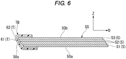
- FIG. 5 and FIG. 6 show a bundle of sheets SS after being subjected to the tape binding processing.
- the plurality of sheets S forming the bundle of sheets SS include a first sheet S1, a second sheet S2, and a plurality of third sheets S3.
- the first sheet S1 is positioned on the lower most surface of the bundle of sheets SS and forms a cover sheet of for the bundle of sheets SS.
- the first sheet S1 is a sheet S conveyed to the processing unit 21 firstly in the bundle of sheets SS.
- the third sheet S3 is positioned on the upper most (or back) surface on the bundle of sheets SS and forms a back cover sheet of the bundle of sheets SS.
- the third sheet S3 is a sheet S conveyed to the processing unit 21 lastly in the bundle of sheets SS.
- the second sheet S2 is positioned between the first sheet S1 and the third sheet S3 and forms an intermediate-page sheet of the bundle of sheets SS.
- the second sheet S2 may be a single sheet or a plurality of sheets.
- the bundle of sheets SS may be formed by only the first sheet S1 and the third sheet S3 without the second sheet S2.
- an adhesive layer 61 is integrally formed on one surface of base material (protective film 62). An end edge of the adhesive layer 61 faces the outer peripheral edge of the tape T.
- the bundle of sheets SS includes a front surface 50a, a back surface 50b, and a side portion 50c.
- the front surface 50a is formed by the first sheet S1.
- the back surface 50b is formed by the third sheet S3.
- the side portion 50c is the outer peripheral edge of the bundle of sheets SS and is formed by side edges of a plurality of sheets S between the front surface 50a and the back surface 50b.
- the side portion 50c is formed by side edges of the first sheet S1, the second sheet(s) S2, and the third sheet S3.
- the side portion 50c is formed with only side edges of the first sheet S1 and the third sheet S3.
- the bundle of sheets SS is formed by shifting a plurality of sheets S bit by bit in the sheet conveyance direction D in the stack of sheets S forming the bundle of sheets SS.
- the side portion 50c of both sides of the sheet conveyance direction D in the bundle of sheets SS is formed in a step shape by side edges of a plurality of sheets S and surfaces exposed through shifting of respective sheets S in the second sheet S2.
- the strength of the binding by the tape T to the sheets S2 is the weakest.
- the shifting of the plurality of sheets S is large, the exposure area of the main surfaces is greater in the second sheet(s) S2 and an adhesion area between the tape T and the sheet S is larger on the second sheet (s) S2. In this case, the strength of the binding by the tape T becomes the strongest.
- an amount of the of the plurality of sheets S may be changed to increase or decrease the sheet S surface area contacting the adhesive layer 61 of the tape T in the bundle of sheets SS to adjust the strength of the binding by the tape T.
- the amount of the shift of each of the plurality of sheets S is preferably substantially uniform, the amounts of shift of different ones of the plurality of sheets S may be non-uniform.
- the delivery direction of a strip-like tape T is arranged to be orthogonal to the one side edge SSa of the bundle of sheets SS as shown in Fig. 3 .
- the front surface 50a, the back surface 50b, and the side portion 50c of the bundle of sheets SS are made to stay together (be bound)by the tape T. That is, the adhesive layer 61 of the tape T is adhered to each of the front surface 50a, the back surface 50b, and the side portions 50c of the bundle of sheets SS.
- the one side edge SSa of the bundle of sheets SS is bound and wrapped in three directions by the tape T.
- a portion bound by the tape T along the one side edge SSa of the bundle of sheets SS is referred to as a tape binding portion TB ( Fig. 5 ).
- the bundle preparing unit 22 includes a main guide 31, a subguide 32, a moveable stopper 33, and a switching member 34.
- the main guide 31 guides the sheet S along the sheet surface direction.
- the plurality of sheets S are stacked on the main guide 31 in order to form the bundle of sheets SS.
- the subguide 32 faces the main guide 31 in the sheet thickness direction Z.
- a space in which the bundle of sheets SS is disposed is provided between the main guide 31 and the subguide 32.
- the stopper 33 is provided in the downstream side end portion of the main guide 31 in the sheet conveyance direction D.
- the stopper 33 is movable between a regulating position (indicated by the solid line in FIG. 3 ) and a releasing position (indicated by the two-dot chain line in FIG. 3 ) .
- the stopper 33 may block the sheet(s) S in the regulating position and thereby form a bundle of sheets SS on the main guide 31.
- the stopper 33 when properly positioned releases the sheets S in the releasing position and allows the bundle of sheets SS on the main guide 31 to pass toward the switching member 34.
- the switching member 34 switches the bundle of sheets SS between different conveyance passage direction.
- a direction in which the bundle of sheets SS is conveyed toward the tape binding processing unit 24 is referred to as a "first conveyance direction”.
- a direction in which the bundle of sheets SS is conveyed toward a position (for example, below the bundle preparing unit 22) different from the tape attaching portion 59 is referred to as a "second conveyance direction”.
- the switching member 34 switches the conveyance direction of the bundle of sheets SS between the first conveyance direction and the second conveyance direction.
- the switching member 34 is rotatable between a first conveyance position (indicated by the solid line in FIG. 3 ) to guide the bundle of sheets SS in the first conveyance direction and a second conveyance position (indicated by the dashed line in FIG. 3 ) to guide the bundle of sheets SS in the second conveyance direction.
- the sheet shifting unit 23 includes a first roller 41 and a second roller 42.
- the first roller 41 is attached to a first shaft 43.
- the first roller 41 is a driving roller driven by a motor (not illustrated).
- the axial center (axis of rotation) of the first roller 41 is fixed.
- Materials of the first roller 41 are not particularly limited.
- the first roller 41 is formed of ethylene propylene diene rubber (EPDM).
- the second roller 42 is attached to a second shaft 44.
- the second roller 42 is a driven roller which rotates as a result of rotation of the first roller 41.
- the second roller 42 is movable in directions approaching the first roller 41 or moving away from the first roller 41 by an axial center moving mechanism (not illustrated) .
- the second roller 42 is moved toward the first roller 41 to contact the bundle of sheets SS therebetween from the side of the bundle of sheets SS opposite to the first roller 41.
- the outer peripheral surface 42s of the second roller 42 is softer, i.e., more compliant, than the outer peripheral surface 41s of the first roller 41 and is deformable along the front surface of the bundle of sheets SS (see FIG. 4 ).
- the second roller 42 is formed by sponge or rubber within which a cavity is formed.
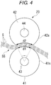
- FIG. 4 illustrates a principle of shifting of a plurality of sheets S of the bundle of sheets SS.
- first length d1 a circumferential length of a portion contacting the bundle of sheets SS
- second length d2 a length of a portion (recessed portion) contacting the bundle of sheets SS in a direction along a circumferential direction of the first roller 41
- the second length d2 is longer than the first length d1.
- the first roller 41 and the second roller 42 are rotated to convey out the bundle of sheets SS to the sheet conveyance direction D.
- the moving distance of the sheet S contacting the outer peripheral surface 42s of the second roller 42 is longer than that of the sheet S contacting the outer peripheral surface 41s of the first roller 41. That is, the conveyed distance of the sheets of the bundle of sheets SS becomes greater in the sheet conveyance direction D as the sheets of the bundle of sheets SS are closer to the second roller 42.
- a state where a plurality of sheets S are shifted in a step shape is formed on the one side edge SSa of the bundle of sheets SS.
- the tape binding processing unit 24 includes an unwinding unit 51, a tape conveyance unit 52, a separation member 53, a winding unit 54, a guide table 55, a cutter 56, a cut length changing unit 57, a tape holding unit 58, and a tape attaching portion 59.
- the unwinding unit 51 holds a raw web roll wound with the strip-like tape T.
- the unwinding unit 51 supplies the tape T delivered from the raw web roll along the delivery direction (length direction) of the tape T.
- the tape T contains a peelable film 63 in addition to the adhesive layer 61 and the protective film (base material) 62.
- the protective film 62 covers one side surface of the adhesive layer 61.
- the protective film 62 is used integrally with the adhesive layer 61.
- the peelable film 63 covers the other side surface of the adhesive layer 61 from a side opposite to the protective film 62.
- the peelable film 63 is peeled off from the adhesive layer 61 prior to use of the tape T.
- the peelable film 63 is pulled away from the adhesive layer 61 at the separation member 53 and the winding unit 54.
- a film to be peeled off and thereby expose the adhesive surface when the tape T is used is referred to as a "peelable film”.
- a film for also protecting the adhesive layer 61 in a use state of the tape T is referred to as a "protective film”.
- the tape T is attached to the unwinding unit 51 in a state of being accommodated in a cartridge C.
- the cartridge C includes an identification portion ID indicating a type of tape T.
- the identification portion ID may include an IC chip, a barcode, a block pattern, or the like.
- the tape binding processing unit 24 may include a tape information acquisition unit 51a.
- the tape information acquisition unit 51a reads information from the identification portion ID of the cartridge C to acquire information on the type of tape T.
- the tape information acquisition unit 51a may include a sensor, a microswitch, or the like.
- the tape information acquisition unit 51a sends the acquired information on the type of tape T to the post-processing control unit 26.
- the post-processing control unit 26 controls the operation of the tape binding processing unit 24 based on information sent from the tape information acquisition unit 51a.
- the tape conveyance unit 52 conveys the tape T supplied from the unwinding unit 51 along the length direction of the tape T.
- the conveyance direction of the tape conveyance unit 52 is a direction substantially parallel to the sheet thickness direction Z.
- the guide table 55 guides the tape T separated from the peelable film 63.
- the guide table 55 supports the tape T when holding or cutting the tape T.
- the cutter 56 cuts out the strip-like tape T supplied from the unwinding unit 51 to form a sheet-like tape T.
- the cutter 56 is a rotary cutter which includes a cutting blade 56a and a supporting shaft 56b.
- the cutting blade 56a is rotationally driven along with the supporting shaft 56b by a motor ⁇ not illustrated).
- a configuration of the cutter 56 is not limited to the example described above.
- the cutter 56 is movable in directions approaching the tape T or moving away from the tape T by a moving mechanism (not illustrated) .
- the cut length changing unit 57 position determines the delivery length of the tape T cut out by the cutter 56.
- the delivery length of the tape T is sufficient for wrapping around a portion spanning from the front surface 50a to the back surface 50b across the side portion 50c of the one side edge SSa of the bundle of sheets SS in three directions.
- the cut length changing unit 57 includes a moving mechanism 71 for changing a relative position of the cutter 56 with respect to a tip end Te of the tape T supplied from the unwinding unit 51.
- the moving mechanism 71 moves the cutter 56 to change the relative position of the cutter 56 with respect to the tip end Te of the tape T.
- the moving mechanism 71 moves the cutter 56 along the conveyance direction of the tape conveyance unit 52.
- the moving mechanism 71 includes a supporting member 72 supporting the cutter 56 and a driving source 73 moving the cutter 56 along the supporting member 72.
- the supporting member 72 is a lead screw connected to the cutter 56.
- the driving source 73 is a motor which drives the lead screw to move the cutter 56.
- a configuration of the moving mechanism 71 is not limited to the example described above.
- the moving mechanism 71 may change the delivery length of the tape T with respect to the cutter 56 fixed in place and may also change the relative position of the cutter 56 with respect to the tip end Te of the tape T.
- the cut length changing unit 57 is controlled by the post-processing control unit 26.
- the post-processing control unit 26 controls the driving source 73 of the cut length changing unit 57 to move the cutter 56 and changes the length of the tape T cut out by the cutter 56.
- the cut length changing unit 57 changes the length of the tape T cut out by the cutter 56 based on information on the sheet S, information on the tape T, information on the way to bind the bundle of sheets SS and the like.
- the tape holding unit 58 supports the tape T in a state of holding a posture of the tape T substantially flat, with the adhesive side of the tape T facing the one side edge SSa of the bundle of sheets SS.
- the tape holding unit 58 is movable along the length direction of the tape T by a moving mechanism not illustrated.
- the tape holding unit 58 is movable in directions approaching the tape T or moving away from the tape T by a moving mechanism not illustrated.
- the tape attaching portion 59 includes a first urging roller 91, a second urging roller 92, a first spring 93, and a second spring 94.
- the first spring 93 urges the first urging roller 91 toward the second urging roller 92.
- the second spring 94 urges the second urging roller 92 toward the first urging roller 91.
- the one side edge SSa of the bundle of sheets SS, and the tape T, are inserted between the first urging roller 91 and the second urging roller 92 when the tape T is attached to the one side edge SSa.
- the tape T is engaged against the one side edge SSa and begins to be folded such that the one side edge SSa of the bundle of sheets SS is wrapped by the tape attaching portion 59 and the tape T is attached to one side edge SSa of the bundle of sheets SS and over the main surfaces of the first and third sheets S1, S3.
- the bundle preparing unit 22 moves the stopper 33 to the regulating position to block the sheet S conveyed along the main guide in the main guide 31. With this, a plurality of sheets S are stacked in order on the main guide 31 to form a bundle of sheets SS.
- the bundle preparing unit 22 moves the stopper 33 to the releasing position and switches the switching member 34 to the second conveyance position. With this, the bundle of sheets SS is guided to the sheet shifting unit 23.
- the sheet shifting unit 23 moves the second roller 42 toward the first roller 41. With this, the bundle of sheets SS and the outer peripheral surface 42s of the second roller 42 are deformed into a circular arc shape along the outer peripheral surface 41s of the first roller 41.
- the sheet shifting unit 23 determines a sheet shifting amount based on at least one of information on a plurality of sheets S, information on the tape T, information on the way to bind the bundle of sheets SS by the tape T and the like. For example, the sheet shifting unit 23 determines a rotation angle of the first roller 41 as a control amount. The sheet shifting unit 23 moves the first roller 41 forwardly based on the determined rotation angle of the second roller 42 in a state where the bundle of sheets SS is pinched between the first roller 41 and the second roller 42.
- the second roller 42 is rotated as a result of the rotation of the first roller 41 while maintaining a recessed state along the outer peripheral surface 41s of the first roller 41.
- the plurality of sheets S (the bundle of sheets SS) is in a state of where individual sheets are shifted in a step shape in the sheet conveyance direction D on the one side edge SSa of the bundle of sheets SS.
- the tape binding processing unit 24 sets a length of the tape T cut out by the cutter 56 by control of the post-processing control unit 26.
- the tape binding processing unit 24 moves the tape holding unit 58 to a location between one side edge SSa of the bundle of sheets SS and the tape attaching portion (indicated by two-dot chain line in FIG. 3 ) while holding the tape T in the tape holding unit 58.
- the tape binding processing unit 24 cuts out the strip-like tape T with the cutter 56 to form a tape T having a sheet-like length.
- the first roller 41 and the second roller 42 are rotated forwardly to move the one side edge SSa of the bundle of sheets SS toward the tape attaching portion 59.
- one side edge SSa of the bundle of sheets SS abuts against the tape T and the one side edge SSa of the bundle of sheets SS and the tape T are inserted between the first urging roller 91 and the second urging roller 92.
- the first urging roller 91 and the second urging roller 92 each move along an outer, opposed, main surface of the first and third sheets S1, S3 adjacent to the one side edge SSa of the bundle of sheets SS.
- the first urging roller 91 and the second urging roller 92 push against the tape and thus hold it as the one side edge SSa of the bundle of sheets SS is pushed against it.
- the tape binding processing unit 24 is movable in the sheet width direction W by a movement unit including a guide rail which extends in the sheet width direction W.
- the tape binding processing unit 24 may perform the tape binding processing on the bundle of sheets SS in an arbitrary position in the sheet width direction W.
- a configuration of the tape binding processing unit 24 is not limited to a configuration in which the tape binding processing unit 24 moves in the sheet width direction W and the tape binding processing unit 24 may be configured in such a way that a side (bundle preparing unit 22 and sheet shifting unit 23) holding the bundle of sheets SS moves in the sheet width direction W.
- a configuration, in which the tape binding processing unit 24 or the like is movable in the sheet conveyance direction D and the tape binding processing may be performed on the bundle of sheets SS in an arbitrary position in the sheet conveyance direction D, may be adopted.
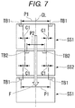
- the first tape binding portion TB1 and the second tape binding portion TB2, which are present on the same side of the bundles, such as the one side portion SSa, are shifted in the sheet width direction W by a distance C1 from each other such that they are not stacked on each other in the sheet width direction W.
- the distance C1 may be the same or different in respective binding portions.
- FIG. 10 and FIG. 11 illustrate a stack of a plurality of bundle of sheets SS discharged in the paper discharge tray 25a.
- a plurality of bundles of sheets SS on the paper discharge tray 25a respectively include tape binding portions TB in the one side edge SSa on the upstream side of each bundle in the sheet conveyance direction D.
- a stack height the plurality of bundles of sheets SS stacked on the paper discharge tray 25a is partially increased due to the thickness of the tape binding portion TB (tape T).
- respective tape binding portions TB of the bundles of sheets SS stacked on each other are shifted to be spaced from each other in the sheet width direction W. With this, the location of the thickness of the tapes T do not overlap one another on each adjacent bundle and the tape binding portions TB of each bundle of sheets SS are not stacked on each other.
- FIG. 12 and FIG. 13 illustrate a stack of a plurality of bundles of sheets SS discharged to the paper discharge tray 25a in a comparative example.
- respective tape binding portions TB of the bundles of sheets SS stacked on each other are shifted to be spaced from each other in the sheet width direction W, at least for each adjacent bound bundle of sheets.
- the thickness of the tape T is not duplicated (double the tape thickness added to the height added of the stack thickness) between the bundles of sheets SS stacked on each other and the increase in the stack height at the one side edge SSa where the tape binding portions are present is reduced, as only the thickness of a sing tape binding portion is added to the thickness of the stack.
- the adhesive layers 61 of the tapes T of each bundle of sheets SS are suppressed from being brought into contact with and adhered to each other in the stack of the bundles of sheets SS. For that reason, the bundles of sheets SS stacked on each other do not easily attach to each other through the tape T.
- the spacing P3 between the three first tape binding portions TB1' and the spacing P4 between pair of second tape binding portions TB2' differ from each other, in particular the spacing of the second tape biding portions from the center of the sheet in the width direction is different than that of the other two first tape binding portions TB2, such that do not overlie each other in a stack thickness direction when stacked.
- the spacing (distance) P5 between the pair of first tape binding portions TB1, the pair of second tape binding portions TB2, and the pair of third tape binding portions TB3 is the substantially the same, and thus only the offset distance from the center of the sheets in the width direction W is different. That is, in each of the three bundles of sheets SS, each pair of tape binding portions TB is moved in the sheet width direction W, but the spacing therebetween is the same for all three pairs of tape binding portions TB1, TB2 and TB3.
- the pattern of locations of the tape binding portions TB on the bundles is repeated, so, for example, where three different tape binding locations are used, a bundle of sheets having the first tape binding portion TB1 locations is next stacked over a bundle of sheets having the third tape binding portion TB3 locations, followed by a bundle of sheets with the second tape binding portion TB2 locations, then a bundle of sheets with the third tape bundle portion TB 3 locations, and then another bundle of sheets with the first tape binding TB1 locations thereon, etc., are stacked.
- a bundle of sheets SS having the third tape binding portion locations TB3 can be located over a bundle of sheets having the first tape binding portion TB1 locations, followed by a bundle with the first or the second tape binding portion TB1, TB2 locations, so long as no two adjacent bundles of sheets SS have the same tape binding locations such that they will contact each other in the stack thickness direction.
- the first bundle of sheets SS1", the second bundle of sheets SS2", and the third bundle of sheets SS3" are stacked on each other in a state where the sides of the bundles of sheets SS1", SS2" and SS3" are substantially aligned with each other.
- one pair of first tape binding portions TB1 of the first bundle of sheets SS1", one pair of second tape binding portions TB2 of the second bundle of sheets SS2", and one pair of third tape binding portions TB3 of the third bundle of sheets SS3" are shifted from each other in the sheet width direction W.
- Respective first tape binding portions TB1, respective second tape binding portions TB2, and respective third tape binding portions TB3 are shifted from each other in the sheet width direction W and thus are not stacked over each other. Respective first tape binding portions TB1, respective second tape binding portions TB2, and respective third tape binding portions TB3 are thus spaced from each other in the sheet width direction W.
- the post-processing control unit 26 may set the tape binding position of the third bundle of sheets SS at the same position as the tape binding position of the first bundle of sheets SS, as long as the tape binding position of the second bundle of sheets SS is avoided. Shift processing for the tape binding position may be automatically performed by the post-processing control unit 26 and may be turned on and off through a user' selecting operation. At least one of a position and the number of tape binding portions TB may be set based on the user' selecting operation.
- the bundle of sheets SS after going through the processing unit 21, is discharged to the paper discharge tray 25a of the paper discharge unit 25 (see FIG. 1 ).
- the paper discharge unit 25 may shift a discharging position of the bundles of sheets SS in the sheet width direction W each time when the bundle of sheets SS is discharged. For example, when a plurality of bundles of sheets SS are discharged, the paper discharge unit 25 may shift a position of the paper discharge tray 25a in the sheet width direction W each time a next bundle of sheets SS is discharged. With this, a plurality of bundles of sheets SS on the paper discharge tray 25a are stacked on each other in the sheet width direction W while each bundle of sheets is shifted in the width direction W from the adjacent bundles of sheets SS.
- first bundle of sheets SS1 and second bundle of sheets SS2 are stacked on each other in a contact state on the paper discharge tray 25a.
- first tape binding portion TB1 of the first bundle of sheets SS1 and the second tape binding portion TB2 of the second bundle of sheets SS2 are shifted from each other in the sheet width direction W by control of the paper discharge unit 25.
- the first tape binding portions TB1 and the second tape binding portions TB2 may be spaced from each other about the center CL in the sheet width direction W without shifting the position of the tape binding portions TB with respect to two consecutive bundles of sheets SS.
- each bundle of sheets SS having the same tape binding position may be prepared without changing a position and/or the number of tape binding portions TB in the bundle of sheets SS.
- the discharging position of the bundles of sheets SS may be shifted in the sheet conveyance direction D instead of shifting the discharging position of the bundle of sheets SS in the sheet width direction W.
- This is especially effective when the tape binding position of the bundle of sheets SS is present in one side of the sheet width direction W. That is, disposition of the tape binding portion TB according to the embodiment may be applied when binding an edge other than the one side edge of the bundle of sheets SS in the sheet width direction W.
- the tape binding portion TB is disposed in the "sheet conveyance direction D" by replacing the "sheet width direction W" of description with reference to FIG. 7 to FIG. 9 described above.
- the post-processing control unit 26 controls at least one of the tape binding processing unit 24 and the paper discharge unit 25 and shifts the position of the tape binding portion TB of the bundle of sheets SS on the paper discharge tray 25a. Respective tape binding portions TB of one pair of bundles of sheets SS stacked on each other in a contact state are shifted from each other in the sheet surface direction by control of the post-processing control unit 26.
- the sheet surface direction includes the sheet width direction W and the sheet conveyance direction D.
- the sheet surface direction is orthogonal to the stacking direction (sheet thickness direction Z) of one pair of bundle of sheets SS.
- the shift amount of the tape binding portions TB is a distance with which at least the tape binding portions TB do not stack over each other (are separated) when viewed in the stacking direction Z of the bundle of sheets SS.
- respective tape binding portions TB of a plurality of bundles of sheets SS stacked on each other in an abutting state in the paper discharge tray 25a are distributed in the sheet surface direction without the tape portions TB being stacked on each other.
- the increase in the stacking thickness in the periphery of the tape binding portions TB of the plurality of bundle of sheets SS is reduced.
- the stacked height in the periphery of the tape binding portions TB of the plurality of piled up bundles of sheets SS is reduced. Accordingly, collapse of the stack of the plurality of bundles of sheets SS may be suppressed.
- Respective tape binding portions TB of one pair of bundles of sheets SS stacked on each other in an abutting state are separated from each other in the sheet surface direction. With this, the tapes T of respective tape binding portions TB are prevented from contacting each other between the plurality of bundles of sheets SS stacked on each other in an abutting state. For that reason, a situation that the adhesive layers of respective tapes T are adhered to each other by being contacted with each other is avoided, and the result of the plurality of piled up bundles of sheets SS being stuck to each other by adhesion of the adhesive layers of respective tapes T may be avoided.
- the post-processing control unit 26 controls the tape binding processing unit 24 and shifts the position of the tape binding portions TB for the bundle of sheets SS in the width direction of the side of the sheets to which the tape binding portion is applied. With this, respective tape binding portions TB of the plurality of bundles of sheets SS stacked on each other are spaced from each other in the sheet surface direction. When a plurality of sheet tape binding portions TB are formed in each bundle of sheets SS, the tape binding position is set such that all of the plurality of tape binding portions TB are spaced from each other.
- one, or a plurality of tape binding processing units 24 equal in number to the maximum number of individual tape bindings desired to be applied to a bundle of sheets SS.
- the tape bundling unit 24 is provided at a first location in the sheet width direction to apply a first tape binding to the bundle of sheets SS, and after the bundle of sheets having the first tape applied thereto is retracted from the tape bundling unit 24, the tape bundling unit 24 is moved in the width direction of the bundle of sheets W, and the tape applying process is repeated to apply a second tape binding to the bundle of sheets SS. This is repeated for the number of tape bindings to be applied to the specific bundle of sheets.
- each tape binding unit is moveable along a slide in a direction generally parallel to the edge of the sheets S to be bound, such as by a motor and lead screw device, or other positioning device.
- two tapes T are used to bind a bundle of sheets SS
- two of the tape binding units 24,each holding a segment of binding tape are simultaneously entered by the bundle of sheets, and the two tapes are simultaneously applied to the edge and adjacent sheet sides thereof.
- three tapes T are used to bind a bundle of sheets SS
- three of the tape binding units 24, each one holding a segment of binding tape are simultaneously entered by the bundle of sheets, and the three tapes are applied to the edge and adjacent side surfaces thereof.
- a number X of the tape binding units 24, each holding a segment of binding tape are simultaneously entered by the bundle of sheets, and X tapes are is applied to the edge and adjacent side surfaces thereof, where X is a whole number greater than one.
- the tape binding portions TB may be distributed in the sheet surface direction by moving the tape binding portion TB location relative to the bundle of sheets SS. For that reason, the stacking height of the plurality of tape binding portions TB of each bundle of sheets SS is reduced after a plurality of bundles of sheets SS are stacked on each other in a state of being aligned along their bound edges or sides.
- the tape binding portions TB of each bundle of sheets SS are spaced from each other in the sheet surface direction after a plurality of bundle of sheets SS are stacked on each other in a state of being aligned along at least their bound edges or sides.
- the post-processing control unit 26 sets the number of the plurality of first tape binding portions TB1 and the number of the plurality of second tape binding portions TB2 to be different from each other. In the modification example, the post-processing control unit 26 sets a difference between the number of first tape binding portions TB1 and the number of second tape binding portions TB2 as one.
- the post-processing control unit 26 makes the spacing P5 between the plurality of first tape binding portions TB1 and the spacing P5 between the plurality of second tape binding portions TB2 the same, but offsets their location from the sheet center CL.
- the post-processing control unit 26 moves the plurality of tape binding portions TB aligned along one side edge SSa of the bundle of sheets SS closer to one end side of one side edge SSa or to the other end side of the sheets.
- the post-processing device 3 includes the tape binding processing unit 24, the paper discharge unit 25, and the post-processing control unit 26.
- the tape binding processing unit 24 performs the tape binding processing on the bundle of sheets SS obtained by stacking a plurality of sheets S.
- the paper discharge unit 25 discharges the bundle of sheets SS subjected to the tape binding processing to the paper discharge tray 25a.
- the paper discharge unit 25 places the first bundle of sheets SS1 and the second bundle of sheets SS2 in the paper discharge tray 25a stacked on each other.
- the first tape binding portion TB1 is formed on the first bundle of sheets SS1 and the second tape binding portion TB2 is formed on the second bundle of sheets SS.
Landscapes
- Engineering & Computer Science (AREA)
- Mechanical Engineering (AREA)
- Textile Engineering (AREA)
- Folding Of Thin Sheet-Like Materials, Special Discharging Devices, And Others (AREA)
Applications Claiming Priority (1)
| Application Number | Priority Date | Filing Date | Title |
|---|---|---|---|
| US15/386,525 US20180170091A1 (en) | 2016-12-21 | 2016-12-21 | Sheet processing device and sheet processing method field |
Publications (2)
| Publication Number | Publication Date |
|---|---|
| EP3348503A2 true EP3348503A2 (de) | 2018-07-18 |
| EP3348503A3 EP3348503A3 (de) | 2018-10-24 |
Family
ID=60673985
Family Applications (1)
| Application Number | Title | Priority Date | Filing Date |
|---|---|---|---|
| EP17208458.4A Withdrawn EP3348503A3 (de) | 2016-12-21 | 2017-12-19 | Blattbearbeitungsvorrichtung und blattbearbeitungsverfahren |
Country Status (3)
| Country | Link |
|---|---|
| US (2) | US20180170091A1 (de) |
| EP (1) | EP3348503A3 (de) |
| CN (1) | CN108217288B (de) |
Families Citing this family (1)
| Publication number | Priority date | Publication date | Assignee | Title |
|---|---|---|---|---|
| US10815086B1 (en) * | 2019-09-10 | 2020-10-27 | Toshiba Tec Kabushiki Kaisha | Sheet binding apparatus and image forming system |
Family Cites Families (15)
| Publication number | Priority date | Publication date | Assignee | Title |
|---|---|---|---|---|
| US3404609A (en) * | 1965-10-11 | 1968-10-08 | Crown Zellerbach Corp | Group collator apparatus and method |
| DE2328659A1 (de) * | 1973-06-06 | 1975-01-02 | Wupa Maschf Gmbh & Co | Verfahren und vorrichtung zum stapeln von bogenzuschnitten mit im verhaeltnis zur zuschnittflaeche grosser stapelhoehe |
| US5096176A (en) * | 1990-12-24 | 1992-03-17 | Pitney Bowes Inc. | Sheet set separation using folded strips |
| CA2079356A1 (en) * | 1991-12-16 | 1993-06-17 | Murray O. Meetze | Removable set retaining system for copy sheets |
| US5540421A (en) * | 1993-07-30 | 1996-07-30 | Canon Kabushiki Kaisha | Book binding apparatus |
| ES2119953T3 (es) * | 1994-02-04 | 1998-10-16 | Ferag Ag | Procedimiento y dispositivo para preparar unidades multiples de productos impresos. |
| JP2947747B2 (ja) * | 1996-04-17 | 1999-09-13 | キヤノン株式会社 | テープ加熱装置及び製本装置 |
| US5897250A (en) * | 1996-04-26 | 1999-04-27 | Canon Kabushiki Kaisha | Sheet processing apparatus |
| JP2000072320A (ja) * | 1998-09-02 | 2000-03-07 | Konica Corp | シート後処理装置及び画像形成装置 |
| US7346309B2 (en) * | 2004-08-05 | 2008-03-18 | Konica Minolta Business Technologies, Inc. | Bookbinding system and image forming system |
| JP2006056671A (ja) * | 2004-08-20 | 2006-03-02 | Konica Minolta Business Technologies Inc | 後処理装置 |
| US8840099B2 (en) * | 2010-12-16 | 2014-09-23 | Gradco Japan Ltd. | Binding apparatus |
| CH704241A1 (de) * | 2010-12-20 | 2012-06-29 | Ferag Ag | Verfahren zum Konfektionieren eines Stapels bzw. einer Kollektion aus lose aufeinanderliegenden ein- oder mehrlagigen Vorprodukten, Zusammenstellungen solcher Vorprodukte sowie ein Applikator zum Herstellen solcher Zusammenstellungen. |
| JP5987452B2 (ja) * | 2012-04-25 | 2016-09-07 | 富士ゼロックス株式会社 | 後処理装置及び画像形成装置 |
| US9688089B2 (en) | 2015-02-11 | 2017-06-27 | Kabushiki Kaisha Toshiba | Sheet glue binding processing apparatus |
-
2016
- 2016-12-21 US US15/386,525 patent/US20180170091A1/en not_active Abandoned
-
2017
- 2017-09-11 CN CN201710816151.8A patent/CN108217288B/zh not_active Expired - Fee Related
- 2017-12-19 EP EP17208458.4A patent/EP3348503A3/de not_active Withdrawn
-
2018
- 2018-11-28 US US16/202,766 patent/US10343442B2/en active Active
Non-Patent Citations (1)
| Title |
|---|
| None |
Also Published As
| Publication number | Publication date |
|---|---|
| US20180170091A1 (en) | 2018-06-21 |
| EP3348503A3 (de) | 2018-10-24 |
| CN108217288A (zh) | 2018-06-29 |
| US20190092071A1 (en) | 2019-03-28 |
| CN108217288B (zh) | 2020-09-25 |
| US10343442B2 (en) | 2019-07-09 |
Similar Documents
| Publication | Publication Date | Title |
|---|---|---|
| US10029880B2 (en) | Sheet bundle binding device and image forming system having the same | |
| US10357988B2 (en) | Paper-made staple and paper-made staple assembly | |
| CN106315290B (zh) | 薄片后处理装置及薄片后处理方法 | |
| CN106042706B (zh) | 片材后处理装置及片材后处理方法 | |
| US10234808B2 (en) | Sheet bundle binding device and image forming system having the same | |
| JP2009018494A (ja) | 製本処理方法及び製本装置並びに画像形成システム | |
| EP3263356B1 (de) | Blattbindungsvorrichtung | |
| US10343442B2 (en) | Sheet processing device and sheet processing method | |
| US7631859B2 (en) | Dual disc stacker/stitcher high speed finisher | |
| JP6227349B2 (ja) | シート後処理装置及びこれを備えた画像形成装置 | |
| US20170087795A1 (en) | Sheet bundle binding device and image forming system having the same | |
| JP3678721B2 (ja) | 用紙整合機構およびそれを備える後処理装置 | |
| JP7075210B2 (ja) | シート処理装置及びこれを備える画像形成システム | |
| JP2009018492A (ja) | 製本装置及び画像形成システム | |
| JP6643817B2 (ja) | シート処理装置及びこれを備えた画像形成装置 | |
| JP6395197B2 (ja) | シート後処理装置及びこれを備えた画像形成装置 | |
| JP7224949B2 (ja) | シート処理装置及びこれを備える画像形成システム | |
| JP4970182B2 (ja) | 製本装置及びこれを備えた画像形成システム | |
| JP6227350B2 (ja) | シート後処理装置及びこれを備えた画像形成装置 | |
| JP6438188B2 (ja) | 紙製ステープル、紙製ステープルユニット及びこれを備えたシート後処理装置 | |
| JP6227351B2 (ja) | シート後処理装置及びこれを備えた画像形成装置 | |
| JP6230858B2 (ja) | シート処理装置及びこれを備えた画像形成装置 | |
| JP7299694B2 (ja) | シート処理装置及びこれを備える画像形成システム | |
| JP6433739B2 (ja) | シート処理装置及びこれを備えた画像形成装置 | |
| JP6205241B2 (ja) | シート処理装置及びこれを備えた画像形成装置 |
Legal Events
| Date | Code | Title | Description |
|---|---|---|---|
| PUAI | Public reference made under article 153(3) epc to a published international application that has entered the european phase |
Free format text: ORIGINAL CODE: 0009012 |
|
| AK | Designated contracting states |
Kind code of ref document: A2 Designated state(s): AL AT BE BG CH CY CZ DE DK EE ES FI FR GB GR HR HU IE IS IT LI LT LU LV MC MK MT NL NO PL PT RO RS SE SI SK SM TR |
|
| AX | Request for extension of the european patent |
Extension state: BA ME |
|
| PUAL | Search report despatched |
Free format text: ORIGINAL CODE: 0009013 |
|
| AK | Designated contracting states |
Kind code of ref document: A3 Designated state(s): AL AT BE BG CH CY CZ DE DK EE ES FI FR GB GR HR HU IE IS IT LI LT LU LV MC MK MT NL NO PL PT RO RS SE SI SK SM TR |
|
| AX | Request for extension of the european patent |
Extension state: BA ME |
|
| RIC1 | Information provided on ipc code assigned before grant |
Ipc: B31F 5/06 20060101ALI20180917BHEP Ipc: B65H 37/04 20060101ALI20180917BHEP Ipc: B42C 1/12 20060101ALI20180917BHEP Ipc: B65H 3/06 20060101AFI20180917BHEP Ipc: B65H 35/00 20060101ALI20180917BHEP Ipc: B42C 9/00 20060101ALI20180917BHEP |
|
| STAA | Information on the status of an ep patent application or granted ep patent |
Free format text: STATUS: THE APPLICATION IS DEEMED TO BE WITHDRAWN |
|
| 18D | Application deemed to be withdrawn |
Effective date: 20190425 |