EP3346885B1 - Support à coulissement pour un écran coulissant - Google Patents
Support à coulissement pour un écran coulissant Download PDFInfo
- Publication number
- EP3346885B1 EP3346885B1 EP16763243.9A EP16763243A EP3346885B1 EP 3346885 B1 EP3346885 B1 EP 3346885B1 EP 16763243 A EP16763243 A EP 16763243A EP 3346885 B1 EP3346885 B1 EP 3346885B1
- Authority
- EP
- European Patent Office
- Prior art keywords
- sliding
- slide bar
- slide
- linear
- lacquer
- Prior art date
- Legal status (The legal status is an assumption and is not a legal conclusion. Google has not performed a legal analysis and makes no representation as to the accuracy of the status listed.)
- Active
Links
- 239000004922 lacquer Substances 0.000 claims description 98
- 239000000203 mixture Substances 0.000 claims description 82
- 239000010410 layer Substances 0.000 claims description 80
- 238000000576 coating method Methods 0.000 claims description 75
- 239000011248 coating agent Substances 0.000 claims description 71
- 229920005989 resin Polymers 0.000 claims description 41
- 239000011347 resin Substances 0.000 claims description 41
- 229910052782 aluminium Inorganic materials 0.000 claims description 40
- XAGFODPZIPBFFR-UHFFFAOYSA-N aluminium Chemical compound [Al] XAGFODPZIPBFFR-UHFFFAOYSA-N 0.000 claims description 40
- 235000014113 dietary fatty acids Nutrition 0.000 claims description 38
- 239000000194 fatty acid Substances 0.000 claims description 38
- 229930195729 fatty acid Natural products 0.000 claims description 38
- 150000004665 fatty acids Chemical class 0.000 claims description 37
- 150000003626 triacylglycerols Chemical class 0.000 claims description 28
- 229920003023 plastic Polymers 0.000 claims description 22
- 239000004033 plastic Substances 0.000 claims description 22
- -1 polyoxymethylenes Polymers 0.000 claims description 19
- 238000000034 method Methods 0.000 claims description 18
- 239000004925 Acrylic resin Substances 0.000 claims description 15
- 229910000831 Steel Inorganic materials 0.000 claims description 15
- 150000001335 aliphatic alkanes Chemical class 0.000 claims description 15
- 150000001875 compounds Chemical class 0.000 claims description 15
- 239000010959 steel Substances 0.000 claims description 15
- 229920000178 Acrylic resin Polymers 0.000 claims description 14
- 125000000217 alkyl group Chemical group 0.000 claims description 14
- 229920000642 polymer Polymers 0.000 claims description 13
- 239000002344 surface layer Substances 0.000 claims description 12
- 125000003118 aryl group Chemical group 0.000 claims description 11
- 125000001183 hydrocarbyl group Chemical group 0.000 claims description 11
- 239000000463 material Substances 0.000 claims description 11
- 150000004671 saturated fatty acids Chemical group 0.000 claims description 8
- 150000001336 alkenes Chemical class 0.000 claims description 7
- 229920000728 polyester Polymers 0.000 claims description 6
- 229920000139 polyethylene terephthalate Polymers 0.000 claims description 6
- 239000005020 polyethylene terephthalate Substances 0.000 claims description 6
- 235000003441 saturated fatty acids Nutrition 0.000 claims description 6
- 229920006324 polyoxymethylene Polymers 0.000 claims description 5
- 239000004696 Poly ether ether ketone Substances 0.000 claims description 4
- 239000004952 Polyamide Substances 0.000 claims description 4
- 229920000331 Polyhydroxybutyrate Polymers 0.000 claims description 4
- 239000004734 Polyphenylene sulfide Substances 0.000 claims description 4
- 125000003342 alkenyl group Chemical group 0.000 claims description 4
- 239000005014 poly(hydroxyalkanoate) Substances 0.000 claims description 4
- 239000005015 poly(hydroxybutyrate) Substances 0.000 claims description 4
- 229920002647 polyamide Polymers 0.000 claims description 4
- 229920006260 polyaryletherketone Polymers 0.000 claims description 4
- 229920001707 polybutylene terephthalate Polymers 0.000 claims description 4
- 229920002530 polyetherether ketone Polymers 0.000 claims description 4
- 229920000903 polyhydroxyalkanoate Polymers 0.000 claims description 4
- 229920000069 polyphenylene sulfide Polymers 0.000 claims description 4
- 229920001343 polytetrafluoroethylene Polymers 0.000 claims description 4
- 239000004810 polytetrafluoroethylene Substances 0.000 claims description 4
- 229920002215 polytrimethylene terephthalate Polymers 0.000 claims description 4
- KXDHJXZQYSOELW-UHFFFAOYSA-N Carbamic acid Chemical group NC(O)=O KXDHJXZQYSOELW-UHFFFAOYSA-N 0.000 claims description 3
- 125000003368 amide group Chemical group 0.000 claims description 3
- 125000002843 carboxylic acid group Chemical group 0.000 claims description 3
- 125000004093 cyano group Chemical group *C#N 0.000 claims description 3
- 125000002887 hydroxy group Chemical group [H]O* 0.000 claims description 3
- 125000000468 ketone group Chemical group 0.000 claims description 3
- 125000002560 nitrile group Chemical group 0.000 claims description 3
- 125000000101 thioether group Chemical group 0.000 claims description 3
- 125000003172 aldehyde group Chemical group 0.000 claims description 2
- 150000004945 aromatic hydrocarbons Chemical class 0.000 claims description 2
- 229920006392 biobased thermoplastic Polymers 0.000 claims description 2
- 239000004626 polylactic acid Substances 0.000 claims description 2
- 239000004800 polyvinyl chloride Substances 0.000 claims description 2
- 229920001169 thermoplastic Polymers 0.000 claims description 2
- 239000004416 thermosoftening plastic Substances 0.000 claims description 2
- 125000005843 halogen group Chemical group 0.000 claims 1
- IPCSVZSSVZVIGE-UHFFFAOYSA-N hexadecanoic acid Chemical compound CCCCCCCCCCCCCCCC(O)=O IPCSVZSSVZVIGE-UHFFFAOYSA-N 0.000 description 34
- 229940057995 liquid paraffin Drugs 0.000 description 24
- POULHZVOKOAJMA-UHFFFAOYSA-N dodecanoic acid Chemical compound CCCCCCCCCCCC(O)=O POULHZVOKOAJMA-UHFFFAOYSA-N 0.000 description 22
- 239000003240 coconut oil Substances 0.000 description 20
- 235000019864 coconut oil Nutrition 0.000 description 20
- 235000021314 Palmitic acid Nutrition 0.000 description 17
- WQEPLUUGTLDZJY-UHFFFAOYSA-N n-Pentadecanoic acid Natural products CCCCCCCCCCCCCCC(O)=O WQEPLUUGTLDZJY-UHFFFAOYSA-N 0.000 description 17
- 235000021355 Stearic acid Nutrition 0.000 description 13
- QIQXTHQIDYTFRH-UHFFFAOYSA-N octadecanoic acid Chemical compound CCCCCCCCCCCCCCCCCC(O)=O QIQXTHQIDYTFRH-UHFFFAOYSA-N 0.000 description 13
- OQCDKBAXFALNLD-UHFFFAOYSA-N octadecanoic acid Natural products CCCCCCCC(C)CCCCCCCCC(O)=O OQCDKBAXFALNLD-UHFFFAOYSA-N 0.000 description 13
- 239000008117 stearic acid Substances 0.000 description 13
- GHVNFZFCNZKVNT-UHFFFAOYSA-N decanoic acid Chemical compound CCCCCCCCCC(O)=O GHVNFZFCNZKVNT-UHFFFAOYSA-N 0.000 description 12
- FUZZWVXGSFPDMH-UHFFFAOYSA-N hexanoic acid Chemical compound CCCCCC(O)=O FUZZWVXGSFPDMH-UHFFFAOYSA-N 0.000 description 12
- VKOBVWXKNCXXDE-UHFFFAOYSA-N icosanoic acid Chemical compound CCCCCCCCCCCCCCCCCCCC(O)=O VKOBVWXKNCXXDE-UHFFFAOYSA-N 0.000 description 12
- WWZKQHOCKIZLMA-UHFFFAOYSA-N octanoic acid Chemical compound CCCCCCCC(O)=O WWZKQHOCKIZLMA-UHFFFAOYSA-N 0.000 description 12
- 238000012360 testing method Methods 0.000 description 12
- TUNFSRHWOTWDNC-HKGQFRNVSA-N tetradecanoic acid Chemical compound CCCCCCCCCCCCC[14C](O)=O TUNFSRHWOTWDNC-HKGQFRNVSA-N 0.000 description 12
- 239000005639 Lauric acid Substances 0.000 description 11
- 229920000180 alkyd Polymers 0.000 description 10
- 229920000877 Melamine resin Polymers 0.000 description 9
- 239000004640 Melamine resin Substances 0.000 description 9
- 238000004070 electrodeposition Methods 0.000 description 9
- 125000000391 vinyl group Chemical group [H]C([*])=C([H])[H] 0.000 description 9
- XEEYBQQBJWHFJM-UHFFFAOYSA-N Iron Chemical compound [Fe] XEEYBQQBJWHFJM-UHFFFAOYSA-N 0.000 description 8
- OKKJLVBELUTLKV-UHFFFAOYSA-N Methanol Chemical compound OC OKKJLVBELUTLKV-UHFFFAOYSA-N 0.000 description 8
- 229910052751 metal Inorganic materials 0.000 description 8
- 239000002184 metal Substances 0.000 description 8
- 229920001187 thermosetting polymer Polymers 0.000 description 8
- 239000000178 monomer Substances 0.000 description 7
- 239000000843 powder Substances 0.000 description 7
- 229920002554 vinyl polymer Polymers 0.000 description 7
- 239000005632 Capric acid (CAS 334-48-5) Substances 0.000 description 6
- 239000005635 Caprylic acid (CAS 124-07-2) Substances 0.000 description 6
- PPBRXRYQALVLMV-UHFFFAOYSA-N Styrene Chemical compound C=CC1=CC=CC=C1 PPBRXRYQALVLMV-UHFFFAOYSA-N 0.000 description 6
- JHIVVAPYMSGYDF-UHFFFAOYSA-N cyclohexanone Chemical compound O=C1CCCCC1 JHIVVAPYMSGYDF-UHFFFAOYSA-N 0.000 description 6
- 229960002446 octanoic acid Drugs 0.000 description 6
- CWYNVVGOOAEACU-UHFFFAOYSA-N Fe2+ Chemical compound [Fe+2] CWYNVVGOOAEACU-UHFFFAOYSA-N 0.000 description 5
- PEDCQBHIVMGVHV-UHFFFAOYSA-N Glycerine Chemical compound OCC(O)CO PEDCQBHIVMGVHV-UHFFFAOYSA-N 0.000 description 5
- 229910052799 carbon Inorganic materials 0.000 description 5
- 239000011521 glass Substances 0.000 description 5
- 229930195733 hydrocarbon Natural products 0.000 description 5
- 150000002430 hydrocarbons Chemical class 0.000 description 5
- 239000007788 liquid Substances 0.000 description 5
- 230000001050 lubricating effect Effects 0.000 description 5
- 239000002245 particle Substances 0.000 description 5
- 235000019271 petrolatum Nutrition 0.000 description 5
- NIXOWILDQLNWCW-UHFFFAOYSA-N 2-Propenoic acid Natural products OC(=O)C=C NIXOWILDQLNWCW-UHFFFAOYSA-N 0.000 description 4
- OKTJSMMVPCPJKN-UHFFFAOYSA-N Carbon Chemical group [C] OKTJSMMVPCPJKN-UHFFFAOYSA-N 0.000 description 4
- RTZKZFJDLAIYFH-UHFFFAOYSA-N Diethyl ether Chemical compound CCOCC RTZKZFJDLAIYFH-UHFFFAOYSA-N 0.000 description 4
- 230000032683 aging Effects 0.000 description 4
- 125000005907 alkyl ester group Chemical group 0.000 description 4
- 150000002148 esters Chemical group 0.000 description 4
- 239000000835 fiber Substances 0.000 description 4
- 238000010438 heat treatment Methods 0.000 description 4
- 230000007774 longterm Effects 0.000 description 4
- 239000000314 lubricant Substances 0.000 description 4
- 125000002496 methyl group Chemical group [H]C([H])([H])* 0.000 description 4
- 239000002480 mineral oil Substances 0.000 description 4
- 235000010446 mineral oil Nutrition 0.000 description 4
- TWNQGVIAIRXVLR-UHFFFAOYSA-N oxo(oxoalumanyloxy)alumane Chemical compound O=[Al]O[Al]=O TWNQGVIAIRXVLR-UHFFFAOYSA-N 0.000 description 4
- 229920006395 saturated elastomer Polymers 0.000 description 4
- 238000005406 washing Methods 0.000 description 4
- SMZOUWXMTYCWNB-UHFFFAOYSA-N 2-(2-methoxy-5-methylphenyl)ethanamine Chemical compound COC1=CC=C(C)C=C1CCN SMZOUWXMTYCWNB-UHFFFAOYSA-N 0.000 description 3
- 239000004215 Carbon black (E152) Substances 0.000 description 3
- LYCAIKOWRPUZTN-UHFFFAOYSA-N Ethylene glycol Chemical compound OCCO LYCAIKOWRPUZTN-UHFFFAOYSA-N 0.000 description 3
- CERQOIWHTDAKMF-UHFFFAOYSA-N Methacrylic acid Chemical compound CC(=C)C(O)=O CERQOIWHTDAKMF-UHFFFAOYSA-N 0.000 description 3
- KWYUFKZDYYNOTN-UHFFFAOYSA-M Potassium hydroxide Chemical compound [OH-].[K+] KWYUFKZDYYNOTN-UHFFFAOYSA-M 0.000 description 3
- YXFVVABEGXRONW-UHFFFAOYSA-N Toluene Chemical compound CC1=CC=CC=C1 YXFVVABEGXRONW-UHFFFAOYSA-N 0.000 description 3
- ZMANZCXQSJIPKH-UHFFFAOYSA-N Triethylamine Chemical compound CCN(CC)CC ZMANZCXQSJIPKH-UHFFFAOYSA-N 0.000 description 3
- YGCOKJWKWLYHTG-UHFFFAOYSA-N [[4,6-bis[bis(hydroxymethyl)amino]-1,3,5-triazin-2-yl]-(hydroxymethyl)amino]methanol Chemical compound OCN(CO)C1=NC(N(CO)CO)=NC(N(CO)CO)=N1 YGCOKJWKWLYHTG-UHFFFAOYSA-N 0.000 description 3
- 239000002253 acid Substances 0.000 description 3
- 239000000654 additive Substances 0.000 description 3
- 239000007795 chemical reaction product Substances 0.000 description 3
- 238000011109 contamination Methods 0.000 description 3
- 238000013461 design Methods 0.000 description 3
- 239000000428 dust Substances 0.000 description 3
- 239000000839 emulsion Substances 0.000 description 3
- 238000002474 experimental method Methods 0.000 description 3
- 239000004744 fabric Substances 0.000 description 3
- 229910001448 ferrous ion Inorganic materials 0.000 description 3
- 125000004435 hydrogen atom Chemical group [H]* 0.000 description 3
- 239000000320 mechanical mixture Substances 0.000 description 3
- 239000003960 organic solvent Substances 0.000 description 3
- 239000003973 paint Substances 0.000 description 3
- 238000006116 polymerization reaction Methods 0.000 description 3
- 239000000047 product Substances 0.000 description 3
- 210000002374 sebum Anatomy 0.000 description 3
- 239000007921 spray Substances 0.000 description 3
- 238000010998 test method Methods 0.000 description 3
- XLYOFNOQVPJJNP-UHFFFAOYSA-N water Substances O XLYOFNOQVPJJNP-UHFFFAOYSA-N 0.000 description 3
- POAOYUHQDCAZBD-UHFFFAOYSA-N 2-butoxyethanol Chemical compound CCCCOCCO POAOYUHQDCAZBD-UHFFFAOYSA-N 0.000 description 2
- TWJNQYPJQDRXPH-UHFFFAOYSA-N 2-cyanobenzohydrazide Chemical compound NNC(=O)C1=CC=CC=C1C#N TWJNQYPJQDRXPH-UHFFFAOYSA-N 0.000 description 2
- HRPVXLWXLXDGHG-UHFFFAOYSA-N Acrylamide Chemical compound NC(=O)C=C HRPVXLWXLXDGHG-UHFFFAOYSA-N 0.000 description 2
- QGZKDVFQNNGYKY-UHFFFAOYSA-N Ammonia Chemical compound N QGZKDVFQNNGYKY-UHFFFAOYSA-N 0.000 description 2
- 239000004593 Epoxy Substances 0.000 description 2
- LFQSCWFLJHTTHZ-UHFFFAOYSA-N Ethanol Chemical compound CCO LFQSCWFLJHTTHZ-UHFFFAOYSA-N 0.000 description 2
- VTLYFUHAOXGGBS-UHFFFAOYSA-N Fe3+ Chemical compound [Fe+3] VTLYFUHAOXGGBS-UHFFFAOYSA-N 0.000 description 2
- KFZMGEQAYNKOFK-UHFFFAOYSA-N Isopropanol Chemical compound CC(C)O KFZMGEQAYNKOFK-UHFFFAOYSA-N 0.000 description 2
- CERQOIWHTDAKMF-UHFFFAOYSA-M Methacrylate Chemical compound CC(=C)C([O-])=O CERQOIWHTDAKMF-UHFFFAOYSA-M 0.000 description 2
- BAPJBEWLBFYGME-UHFFFAOYSA-N Methyl acrylate Chemical compound COC(=O)C=C BAPJBEWLBFYGME-UHFFFAOYSA-N 0.000 description 2
- 235000021360 Myristic acid Nutrition 0.000 description 2
- TUNFSRHWOTWDNC-UHFFFAOYSA-N Myristic acid Natural products CCCCCCCCCCCCCC(O)=O TUNFSRHWOTWDNC-UHFFFAOYSA-N 0.000 description 2
- 125000005396 acrylic acid ester group Chemical group 0.000 description 2
- 125000002015 acyclic group Chemical group 0.000 description 2
- 230000001070 adhesive effect Effects 0.000 description 2
- WNLRTRBMVRJNCN-UHFFFAOYSA-N adipic acid Chemical compound OC(=O)CCCCC(O)=O WNLRTRBMVRJNCN-UHFFFAOYSA-N 0.000 description 2
- 150000008064 anhydrides Chemical class 0.000 description 2
- 230000009286 beneficial effect Effects 0.000 description 2
- 150000001721 carbon Chemical group 0.000 description 2
- 239000002801 charged material Substances 0.000 description 2
- 230000006835 compression Effects 0.000 description 2
- 238000007906 compression Methods 0.000 description 2
- 238000004132 cross linking Methods 0.000 description 2
- 230000003247 decreasing effect Effects 0.000 description 2
- 230000000694 effects Effects 0.000 description 2
- 238000009503 electrostatic coating Methods 0.000 description 2
- 150000002118 epoxides Chemical class 0.000 description 2
- 125000004494 ethyl ester group Chemical group 0.000 description 2
- 229910001447 ferric ion Inorganic materials 0.000 description 2
- 239000010931 gold Substances 0.000 description 2
- 229910052737 gold Inorganic materials 0.000 description 2
- 150000004820 halides Chemical group 0.000 description 2
- FPYJFEHAWHCUMM-UHFFFAOYSA-N maleic anhydride Chemical compound O=C1OC(=O)C=C1 FPYJFEHAWHCUMM-UHFFFAOYSA-N 0.000 description 2
- 150000007524 organic acids Chemical class 0.000 description 2
- 230000003647 oxidation Effects 0.000 description 2
- 238000007254 oxidation reaction Methods 0.000 description 2
- 239000012188 paraffin wax Substances 0.000 description 2
- 229920001225 polyester resin Polymers 0.000 description 2
- 239000004645 polyester resin Substances 0.000 description 2
- 150000007519 polyprotic acids Polymers 0.000 description 2
- 229920005749 polyurethane resin Polymers 0.000 description 2
- 238000007789 sealing Methods 0.000 description 2
- CXMXRPHRNRROMY-UHFFFAOYSA-N sebacic acid Chemical compound OC(=O)CCCCCCCCC(O)=O CXMXRPHRNRROMY-UHFFFAOYSA-N 0.000 description 2
- 239000000243 solution Substances 0.000 description 2
- 238000003756 stirring Methods 0.000 description 2
- 239000000126 substance Substances 0.000 description 2
- 150000005846 sugar alcohols Polymers 0.000 description 2
- VZGDMQKNWNREIO-UHFFFAOYSA-N tetrachloromethane Chemical compound ClC(Cl)(Cl)Cl VZGDMQKNWNREIO-UHFFFAOYSA-N 0.000 description 2
- UFTFJSFQGQCHQW-UHFFFAOYSA-N triformin Chemical compound O=COCC(OC=O)COC=O UFTFJSFQGQCHQW-UHFFFAOYSA-N 0.000 description 2
- PVNIQBQSYATKKL-UHFFFAOYSA-N tripalmitin Chemical compound CCCCCCCCCCCCCCCC(=O)OCC(OC(=O)CCCCCCCCCCCCCCC)COC(=O)CCCCCCCCCCCCCCC PVNIQBQSYATKKL-UHFFFAOYSA-N 0.000 description 2
- 150000004670 unsaturated fatty acids Chemical group 0.000 description 2
- JHPBZFOKBAGZBL-UHFFFAOYSA-N (3-hydroxy-2,2,4-trimethylpentyl) 2-methylprop-2-enoate Chemical compound CC(C)C(O)C(C)(C)COC(=O)C(C)=C JHPBZFOKBAGZBL-UHFFFAOYSA-N 0.000 description 1
- 229920002818 (Hydroxyethyl)methacrylate Polymers 0.000 description 1
- JDCCCHBBXRQRGU-UHFFFAOYSA-N 5-phenylpenta-2,4-dienenitrile Chemical compound N#CC=CC=CC1=CC=CC=C1 JDCCCHBBXRQRGU-UHFFFAOYSA-N 0.000 description 1
- NIXOWILDQLNWCW-UHFFFAOYSA-M Acrylate Chemical compound [O-]C(=O)C=C NIXOWILDQLNWCW-UHFFFAOYSA-M 0.000 description 1
- NLHHRLWOUZZQLW-UHFFFAOYSA-N Acrylonitrile Chemical compound C=CC#N NLHHRLWOUZZQLW-UHFFFAOYSA-N 0.000 description 1
- OMPJBNCRMGITSC-UHFFFAOYSA-N Benzoylperoxide Chemical class C=1C=CC=CC=1C(=O)OOC(=O)C1=CC=CC=C1 OMPJBNCRMGITSC-UHFFFAOYSA-N 0.000 description 1
- JIGUQPWFLRLWPJ-UHFFFAOYSA-N Ethyl acrylate Chemical compound CCOC(=O)C=C JIGUQPWFLRLWPJ-UHFFFAOYSA-N 0.000 description 1
- JOYRKODLDBILNP-UHFFFAOYSA-N Ethyl urethane Chemical compound CCOC(N)=O JOYRKODLDBILNP-UHFFFAOYSA-N 0.000 description 1
- KRHYYFGTRYWZRS-UHFFFAOYSA-M Fluoride anion Chemical compound [F-] KRHYYFGTRYWZRS-UHFFFAOYSA-M 0.000 description 1
- UFHFLCQGNIYNRP-UHFFFAOYSA-N Hydrogen Chemical compound [H][H] UFHFLCQGNIYNRP-UHFFFAOYSA-N 0.000 description 1
- WOBHKFSMXKNTIM-UHFFFAOYSA-N Hydroxyethyl methacrylate Chemical compound CC(=C)C(=O)OCCO WOBHKFSMXKNTIM-UHFFFAOYSA-N 0.000 description 1
- YIVJZNGAASQVEM-UHFFFAOYSA-N Lauroyl peroxide Chemical class CCCCCCCCCCCC(=O)OOC(=O)CCCCCCCCCCC YIVJZNGAASQVEM-UHFFFAOYSA-N 0.000 description 1
- VVQNEPGJFQJSBK-UHFFFAOYSA-N Methyl methacrylate Chemical compound COC(=O)C(C)=C VVQNEPGJFQJSBK-UHFFFAOYSA-N 0.000 description 1
- CNCOEDDPFOAUMB-UHFFFAOYSA-N N-Methylolacrylamide Chemical compound OCNC(=O)C=C CNCOEDDPFOAUMB-UHFFFAOYSA-N 0.000 description 1
- 239000004264 Petrolatum Substances 0.000 description 1
- 239000002202 Polyethylene glycol Substances 0.000 description 1
- 230000002378 acidificating effect Effects 0.000 description 1
- 150000007513 acids Chemical class 0.000 description 1
- 229920002877 acrylic styrene acrylonitrile Polymers 0.000 description 1
- 230000000996 additive effect Effects 0.000 description 1
- 239000000853 adhesive Substances 0.000 description 1
- 239000001361 adipic acid Substances 0.000 description 1
- 235000011037 adipic acid Nutrition 0.000 description 1
- 125000001931 aliphatic group Chemical group 0.000 description 1
- 239000004411 aluminium Substances 0.000 description 1
- 229910021529 ammonia Inorganic materials 0.000 description 1
- 239000007864 aqueous solution Substances 0.000 description 1
- 235000019400 benzoyl peroxide Nutrition 0.000 description 1
- 239000011203 carbon fibre reinforced carbon Substances 0.000 description 1
- 150000001735 carboxylic acids Chemical class 0.000 description 1
- 239000004359 castor oil Substances 0.000 description 1
- 235000019438 castor oil Nutrition 0.000 description 1
- 239000003054 catalyst Substances 0.000 description 1
- 125000002091 cationic group Chemical group 0.000 description 1
- 238000006243 chemical reaction Methods 0.000 description 1
- CBGUOGMQLZIXBE-XGQKBEPLSA-N clobetasol propionate Chemical compound C1CC2=CC(=O)C=C[C@]2(C)[C@]2(F)[C@@H]1[C@@H]1C[C@H](C)[C@@](C(=O)CCl)(OC(=O)CC)[C@@]1(C)C[C@@H]2O CBGUOGMQLZIXBE-XGQKBEPLSA-N 0.000 description 1
- 239000003086 colorant Substances 0.000 description 1
- 230000000052 comparative effect Effects 0.000 description 1
- 239000002131 composite material Substances 0.000 description 1
- 229940069205 cormax Drugs 0.000 description 1
- 239000002537 cosmetic Substances 0.000 description 1
- 230000007812 deficiency Effects 0.000 description 1
- 230000001419 dependent effect Effects 0.000 description 1
- 238000000151 deposition Methods 0.000 description 1
- 230000008021 deposition Effects 0.000 description 1
- 239000003599 detergent Substances 0.000 description 1
- 238000003618 dip coating Methods 0.000 description 1
- 238000007598 dipping method Methods 0.000 description 1
- WNAHIZMDSQCWRP-UHFFFAOYSA-N dodecane-1-thiol Chemical compound CCCCCCCCCCCCS WNAHIZMDSQCWRP-UHFFFAOYSA-N 0.000 description 1
- 230000005684 electric field Effects 0.000 description 1
- 238000001962 electrophoresis Methods 0.000 description 1
- 238000005516 engineering process Methods 0.000 description 1
- 239000003822 epoxy resin Substances 0.000 description 1
- 239000000945 filler Substances 0.000 description 1
- 229960005150 glycerol Drugs 0.000 description 1
- 235000011187 glycerol Nutrition 0.000 description 1
- ZEMPKEQAKRGZGQ-XOQCFJPHSA-N glycerol triricinoleate Natural products CCCCCC[C@@H](O)CC=CCCCCCCCC(=O)OC[C@@H](COC(=O)CCCCCCCC=CC[C@@H](O)CCCCCC)OC(=O)CCCCCCCC=CC[C@H](O)CCCCCC ZEMPKEQAKRGZGQ-XOQCFJPHSA-N 0.000 description 1
- PCHJSUWPFVWCPO-UHFFFAOYSA-N gold Chemical compound [Au] PCHJSUWPFVWCPO-UHFFFAOYSA-N 0.000 description 1
- 239000001257 hydrogen Substances 0.000 description 1
- 229910052739 hydrogen Inorganic materials 0.000 description 1
- 238000007654 immersion Methods 0.000 description 1
- 229910052500 inorganic mineral Inorganic materials 0.000 description 1
- 229910052742 iron Inorganic materials 0.000 description 1
- 229960004592 isopropanol Drugs 0.000 description 1
- 230000005923 long-lasting effect Effects 0.000 description 1
- 238000005259 measurement Methods 0.000 description 1
- 229910021645 metal ion Inorganic materials 0.000 description 1
- 150000004702 methyl esters Chemical class 0.000 description 1
- 239000011707 mineral Substances 0.000 description 1
- 235000010755 mineral Nutrition 0.000 description 1
- NJTGANWAUPEOAX-UHFFFAOYSA-N molport-023-220-454 Chemical compound OCC(O)CO.OCC(O)CO NJTGANWAUPEOAX-UHFFFAOYSA-N 0.000 description 1
- DNTMQTKDNSEIFO-UHFFFAOYSA-N n-(hydroxymethyl)-2-methylprop-2-enamide Chemical compound CC(=C)C(=O)NCO DNTMQTKDNSEIFO-UHFFFAOYSA-N 0.000 description 1
- 230000003472 neutralizing effect Effects 0.000 description 1
- 230000009965 odorless effect Effects 0.000 description 1
- 239000003921 oil Substances 0.000 description 1
- 235000019198 oils Nutrition 0.000 description 1
- 235000005985 organic acids Nutrition 0.000 description 1
- 238000010525 oxidative degradation reaction Methods 0.000 description 1
- 230000001590 oxidative effect Effects 0.000 description 1
- 238000010422 painting Methods 0.000 description 1
- PNJWIWWMYCMZRO-UHFFFAOYSA-N pent‐4‐en‐2‐one Natural products CC(=O)CC=C PNJWIWWMYCMZRO-UHFFFAOYSA-N 0.000 description 1
- 229940066842 petrolatum Drugs 0.000 description 1
- 239000004014 plasticizer Substances 0.000 description 1
- 229920000647 polyepoxide Polymers 0.000 description 1
- 229920001223 polyethylene glycol Polymers 0.000 description 1
- 239000002685 polymerization catalyst Substances 0.000 description 1
- 239000011148 porous material Substances 0.000 description 1
- 235000011118 potassium hydroxide Nutrition 0.000 description 1
- QMRNDFMLWNAFQR-UHFFFAOYSA-N prop-2-enenitrile;prop-2-enoic acid;styrene Chemical compound C=CC#N.OC(=O)C=C.C=CC1=CC=CC=C1 QMRNDFMLWNAFQR-UHFFFAOYSA-N 0.000 description 1
- 230000001105 regulatory effect Effects 0.000 description 1
- 230000000284 resting effect Effects 0.000 description 1
- 238000005096 rolling process Methods 0.000 description 1
- 239000002356 single layer Substances 0.000 description 1
- 239000007787 solid Substances 0.000 description 1
- 239000008247 solid mixture Substances 0.000 description 1
- 238000005507 spraying Methods 0.000 description 1
- 239000007858 starting material Substances 0.000 description 1
- 230000003068 static effect Effects 0.000 description 1
- 239000000758 substrate Substances 0.000 description 1
- 230000003319 supportive effect Effects 0.000 description 1
- 235000013311 vegetables Nutrition 0.000 description 1
- 239000003871 white petrolatum Substances 0.000 description 1
Images


Classifications
-
- A—HUMAN NECESSITIES
- A47—FURNITURE; DOMESTIC ARTICLES OR APPLIANCES; COFFEE MILLS; SPICE MILLS; SUCTION CLEANERS IN GENERAL
- A47H—FURNISHINGS FOR WINDOWS OR DOORS
- A47H1/00—Curtain suspension devices
- A47H1/04—Curtain rails
-
- A—HUMAN NECESSITIES
- A47—FURNITURE; DOMESTIC ARTICLES OR APPLIANCES; COFFEE MILLS; SPICE MILLS; SUCTION CLEANERS IN GENERAL
- A47H—FURNISHINGS FOR WINDOWS OR DOORS
- A47H15/00—Runners or gliders for supporting curtains on rails or rods
- A47H15/04—Gliders
-
- C—CHEMISTRY; METALLURGY
- C09—DYES; PAINTS; POLISHES; NATURAL RESINS; ADHESIVES; COMPOSITIONS NOT OTHERWISE PROVIDED FOR; APPLICATIONS OF MATERIALS NOT OTHERWISE PROVIDED FOR
- C09D—COATING COMPOSITIONS, e.g. PAINTS, VARNISHES OR LACQUERS; FILLING PASTES; CHEMICAL PAINT OR INK REMOVERS; INKS; CORRECTING FLUIDS; WOODSTAINS; PASTES OR SOLIDS FOR COLOURING OR PRINTING; USE OF MATERIALS THEREFOR
- C09D133/00—Coating compositions based on homopolymers or copolymers of compounds having one or more unsaturated aliphatic radicals, each having only one carbon-to-carbon double bond, and at least one being terminated by only one carboxyl radical, or of salts, anhydrides, esters, amides, imides, or nitriles thereof; Coating compositions based on derivatives of such polymers
- C09D133/04—Homopolymers or copolymers of esters
- C09D133/06—Homopolymers or copolymers of esters of esters containing only carbon, hydrogen and oxygen, the oxygen atom being present only as part of the carboxyl radical
- C09D133/10—Homopolymers or copolymers of methacrylic acid esters
-
- C—CHEMISTRY; METALLURGY
- C09—DYES; PAINTS; POLISHES; NATURAL RESINS; ADHESIVES; COMPOSITIONS NOT OTHERWISE PROVIDED FOR; APPLICATIONS OF MATERIALS NOT OTHERWISE PROVIDED FOR
- C09D—COATING COMPOSITIONS, e.g. PAINTS, VARNISHES OR LACQUERS; FILLING PASTES; CHEMICAL PAINT OR INK REMOVERS; INKS; CORRECTING FLUIDS; WOODSTAINS; PASTES OR SOLIDS FOR COLOURING OR PRINTING; USE OF MATERIALS THEREFOR
- C09D191/00—Coating compositions based on oils, fats or waxes; Coating compositions based on derivatives thereof
- C09D191/06—Waxes
-
- C—CHEMISTRY; METALLURGY
- C09—DYES; PAINTS; POLISHES; NATURAL RESINS; ADHESIVES; COMPOSITIONS NOT OTHERWISE PROVIDED FOR; APPLICATIONS OF MATERIALS NOT OTHERWISE PROVIDED FOR
- C09D—COATING COMPOSITIONS, e.g. PAINTS, VARNISHES OR LACQUERS; FILLING PASTES; CHEMICAL PAINT OR INK REMOVERS; INKS; CORRECTING FLUIDS; WOODSTAINS; PASTES OR SOLIDS FOR COLOURING OR PRINTING; USE OF MATERIALS THEREFOR
- C09D5/00—Coating compositions, e.g. paints, varnishes or lacquers, characterised by their physical nature or the effects produced; Filling pastes
-
- C—CHEMISTRY; METALLURGY
- C10—PETROLEUM, GAS OR COKE INDUSTRIES; TECHNICAL GASES CONTAINING CARBON MONOXIDE; FUELS; LUBRICANTS; PEAT
- C10M—LUBRICATING COMPOSITIONS; USE OF CHEMICAL SUBSTANCES EITHER ALONE OR AS LUBRICATING INGREDIENTS IN A LUBRICATING COMPOSITION
- C10M145/00—Lubricating compositions characterised by the additive being a macromolecular compound containing oxygen
- C10M145/18—Macromolecular compounds obtained otherwise than by reactions only involving carbon-to-carbon unsaturated bonds
-
- E—FIXED CONSTRUCTIONS
- E05—LOCKS; KEYS; WINDOW OR DOOR FITTINGS; SAFES
- E05D—HINGES OR SUSPENSION DEVICES FOR DOORS, WINDOWS OR WINGS
- E05D15/00—Suspension arrangements for wings
- E05D15/06—Suspension arrangements for wings for wings sliding horizontally more or less in their own plane
- E05D15/0621—Details, e.g. suspension or supporting guides
- E05D15/0626—Details, e.g. suspension or supporting guides for wings suspended at the top
- E05D15/0647—Details, e.g. suspension or supporting guides for wings suspended at the top on sliding blocks
-
- E—FIXED CONSTRUCTIONS
- E05—LOCKS; KEYS; WINDOW OR DOOR FITTINGS; SAFES
- E05D—HINGES OR SUSPENSION DEVICES FOR DOORS, WINDOWS OR WINGS
- E05D15/00—Suspension arrangements for wings
- E05D15/06—Suspension arrangements for wings for wings sliding horizontally more or less in their own plane
- E05D15/0621—Details, e.g. suspension or supporting guides
- E05D15/0626—Details, e.g. suspension or supporting guides for wings suspended at the top
- E05D15/0652—Tracks
-
- E—FIXED CONSTRUCTIONS
- E05—LOCKS; KEYS; WINDOW OR DOOR FITTINGS; SAFES
- E05D—HINGES OR SUSPENSION DEVICES FOR DOORS, WINDOWS OR WINGS
- E05D15/00—Suspension arrangements for wings
- E05D15/06—Suspension arrangements for wings for wings sliding horizontally more or less in their own plane
- E05D15/0621—Details, e.g. suspension or supporting guides
- E05D15/066—Details, e.g. suspension or supporting guides for wings supported at the bottom
- E05D15/0682—Details, e.g. suspension or supporting guides for wings supported at the bottom on sliding blocks
-
- E—FIXED CONSTRUCTIONS
- E05—LOCKS; KEYS; WINDOW OR DOOR FITTINGS; SAFES
- E05Y—INDEXING SCHEME ASSOCIATED WITH SUBCLASSES E05D AND E05F, RELATING TO CONSTRUCTION ELEMENTS, ELECTRIC CONTROL, POWER SUPPLY, POWER SIGNAL OR TRANSMISSION, USER INTERFACES, MOUNTING OR COUPLING, DETAILS, ACCESSORIES, AUXILIARY OPERATIONS NOT OTHERWISE PROVIDED FOR, APPLICATION THEREOF
- E05Y2900/00—Application of doors, windows, wings or fittings thereof
- E05Y2900/10—Application of doors, windows, wings or fittings thereof for buildings or parts thereof
- E05Y2900/13—Type of wing
- E05Y2900/132—Doors
Definitions
- the present invention relates to a sliding screen sliding system, the sliding system comprising a slide bar having a sliding surface with low friction. Further, the invention relates to a sliding screen arrangement comprising such a sliding system.
- Wardrobes having sliding doors are well-known in the art (cf. e.g. DE 298 13 478 ).
- the doors are arranged with supportive ball bearings, e.g. wheels rolling over a rail, at the upper end of the door and steering means, e.g. pins, at the lower.
- Ball bearings are working well, but suffer from being somewhat dust sensitive.
- the start-stop resistance is very low if the doors are to be easily moveable; an inherent feature of ball bearings. At the end-positions, this may be partly overcome by providing resting end-positions provided with e.g. heads or recesses, for the wheels. However, this would not overcome the low start-stop resistance at intermediate positions. This type of problem is even more pronounced in heavier doors, such as glass doors that are used for patio doors and patio windows of glazed-in patios, and glass doors and glass windows of glazed-in balconies.
- Sliding kitchen doors being less heavy than wardrobe sliding doors, are typically not provided with ball bearings, but are mounted standing in a sliding groove, i.e. a linear plain bearing.
- a linear plain bearing For lighter doors this may work well, though the sliding resistance may be fairly high; especially at start.
- linear plain bearings typically provide too high sliding resistance for practical use; especially at start. Further, such linear plain bearings are sensitive to dust contamination affecting the sliding resistance very negatively.
- curtains represent another type of sliding screens. Also in this application there is a need for low sliding resistance, especially a low start resistance.
- Document JP405076447A discloses an example of a sliding system for curtains.
- a sliding screen sliding system comprising a linear slide bar having a slide surface coated with a lacquer comprising a resin, the lacquer in turn is at least partly coated with a lipophilic composition coating to provide a slide layer with lowered friction, and at least one sliding member.
- This provides for a low friction slide bar with efficient function in sliding screen systems.
- the linear slide bar and the sliding member are arranged in contact and the interface between the slide layer of the slide bar and the sliding member forms a linear plain bearing to allow for linear movement of the sliding member along the longitudinal axis of the linear slide bar.
- the sliding member is provided with a fastening arrangement adapted for connection to a sliding screen to allow for linear movement of the sliding screen along the longitudinal axis of the linear slide bar. At least the part of the sliding member being in contact with the slide layer is made of plastic.
- the part of said sliding member to slide over the slide layer may be configured as a blade extending in the sliding direction.
- the slide layer may arranged at a track, e.g. a groove or a hill, extending along the longitudinal axis of the slide bar. Presence of a track improves the control of the lateral position of the sliding member in relation to the slide bar when the sliding member slides along the slide bar.
- the slide bar may be an aluminum or steel bar.
- the slide surface may be lacquered by electrocoating or autodeposition in a bath containing the lacquer, or by electrostatic coating with a powder lacquer or by wet spraying with a liquid lacquer.
- the slide bar may be a linear, preferably anodized, aluminum profile, having a surface layer onto which the lacquer has been applied.
- the thickness of the anodized oxide surface layer may be at least 5 micrometers, preferably at least 10 micrometers.
- the surface layer may be electrophoretically, such as anaphoretically, coated with an acrylic resin and subsequently heat cured to form the lacquer.
- the lipophilic composition coating comprises compounds comprising C6 to C40, such as C8 to C30, or even C10 to C24, non-aromatic hydrocarbyl groups, such as alkenyl groups and/or alkyl groups, e.g. alkyl groups.
- a sliding screen arrangement comprising the sliding system and a sliding screen.
- the sliding member is arranged to support the sliding screen to allow for linear movement of the sliding screen along the longitudinal axis of the linear slide bar.
- the sliding screen may be a sliding door or a sliding curtain.
- an alternative sliding screen sliding system comprising at least one sliding member having a slide surface coated with a lacquer comprising a resin, wherein said lacquer in turn is at least partly coated with a lipophilic composition coating to provide a slide layer with lowered friction, and a linear slide bar.
- the linear slide bar and the sliding member are arranged in contact, whereby the interface between sliding member and the linear slide bar forms a linear plain bearing to allow for linear movement of the sliding member along the longitudinal axis of the linear slide bar.
- the sliding member is provided with a fastening arrangement adapted for connection to a sliding screen to allow for linear movement of the sliding screen along the longitudinal axis of the linear slide bar. At least the part of said linear slide bar being in contact with the slide layer is made of plastic.
- the present inventors have surprisingly found that coating a surface lacquered with a resin, for example an acrylic resin, with a lipophilic composition, such as for example sebum (natural or artificial), coconut oil, liquid paraffin, etc., provides a slide layer with extremely low friction (sliding resistance).
- a lipophilic composition such as for example sebum (natural or artificial), coconut oil, liquid paraffin, etc.
- a sliding screen sliding system comprising a linear slide bar 10; 110; 210; 310 having a slide surface 14 coated with a lacquer 16 comprising a resin and at least one sliding member 20; 120; 220; 320.
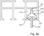
- the provided sliding screen sliding system may for example be in the form of a sliding door sliding system 1;101; 201 for a sliding door 30; 130; 230, or as illustrated in Fig. 8 in the form of a sliding curtain sliding system 301 for a sliding curtain 330.
- the lacquer 16 is in turn at least partly coated with a lipophilic composition coating 18 to provide a slide layer 19 with lowered friction.
- the sliding friction is not just temporarily lowered, but long term low sliding friction is obtained.
- the lubricating coating may be permanent, dispensing with the need to replenish the lubricating coating. Further, very low amounts of the lipophilic composition are needed to provide lowered friction. Thus, contamination of the lubricating coating does not pose any pronounced problem, as the coating, due to the very low amount present, does not have substantial adhesive properties. This is in contrast to the normal use of lubricants in plain bearings. Further, exposure to contaminations, e.g. dust etc., has been shown not to affect the lowered friction. Neither is the lubricating coating sensitive to washing. Wiping the slide bar 10 with a dry and/or wet cloth, does not affect the lowered friction. These properties make the slide bar 10 very useful for sliding wardrobe doors and similar applications.
- sliding screen is intended to mean plate like objects that may slide in a horizontal direction to permit or restrict access to and/or permit or restrict viewing of a certain area.
- the phrase “sliding screen” include, for example, sliding doors of wardrobes, sliding doors for cupboards, sliding doors for kitchen cupboards, sliding doors for glazed-in patios or balconies, sliding windows for glazed-in patios and balconies, sliding doors, with or without glass, that separate rooms in an apartment, house or office space, sliding curtains that cover windows or doors, sliding curtains that separate rooms or parts of rooms in an apartment, house or office space, etc.
- a linear plain bearing is provided as shown in Figs. 1 , 3 , 7 , and 8 .
- the interface between the slide layer of the slide bar 10; 110; 210; 310 and the sliding member 20; 120; 220; 320 thus forms a linear plain bearing to allow for linear movement of the sliding member 20; 120; 220; 320 along the longitudinal axis of the linear slide bar 10; 110; 210; 310.
- the sliding system 1; 101; 201; 301 is arranged to support a sliding screen 30; 130; 230; 330 connected to the sliding member 20; 120; 220; 320 to allow for linear movement of the sliding screen 30; 130; 230; 330 along the longitudinal axis of the linear slide bar 10; 110; 210; 310.
- Such a low amount of the lipophilic composition coating 18 is needed, that the lipophilic composition may be applied to a sliding member 20; 120; 220; 320 rather than to the slide bar 10; 110; 210; 310.
- the lipophilic composition will be transferred to the slide bar 10; 110; 210; 310 to provide a lipophilic composition coating 18.
- the lipophilic composition coating 18 could be applied to the slide bar 10; 110; 210; 310, to the sliding member 20; 120; 220; 320, or both.
- the slide bar 10; 110; 210; 310 is typically made from a hard material, such as metal or glass. Especially, the surface of the slide bar 10; 110; 210; 310 should preferably be hard.
- the Vickers hardness of the material from which the slide bar 10; 110; 210; 310 is made may be at least 50 MPa, more preferably at least 100 MPa, even more preferably at least 150 MPa, and most preferably at least 300 MPa.
- the slide bar 10; 110; 210; 310 is a metal bar, such as an aluminum bar or a steel bar. While it is preferred if an aluminum bar has an oxide layer, also a raw, i.e. not oxidized, lacquered aluminum bar may be used. It is however preferred if the surface of the aluminum bar is oxidized to provide the aluminum bar with a hard oxide surface layer.
- the slide bar 10; 110; 210; 310 may be an aluminum bar.
- the surface of the aluminum bar coated with the lacquer 16 may be an aluminum oxide layer.
- the thickness of such oxide layer may be at least 5 micrometers, more preferably at least 10 micrometers. Further, the thickness of the oxide layer may be less than 250 micrometers, such as less than 100 micrometers or less than 50 micrometers.
- the durability and hardness of the surface of aluminum profiles may be improved by oxidation due to the properties of aluminum oxide.
- the oxide layer initially provided by anodically oxidation is porous.
- a hard, stiff bar such as aluminum or steel bar, may accept far more heavy loads and still provide low friction.
- the low friction slide bar 10; 110; 210; 310 is a linear aluminum profile.
- the linear aluminum profile is oxidized (e.g. anodized) in order to increase the hardness of the surface.
- the profile is typically anaphoretically coated with an acrylic resin subsequently heat cured, thereby providing a linear slide bar 10; 110; 210; 310 having lacquered slide surface 14.
- the aluminum profile may be anodized to obtain an anodized layer thickness of at least 5 micrometers, more preferably at least 10 micrometers, prior to application of the resin of the lacquer. Further, thickness of the anodized layer may be less than 250 micrometers, such as less than 100 micrometers or less than 50 micrometers.
- Such profiles may be obtained via the Honny process (cf. above) or one of its derivatives.
- the Honny process is used to provide white, glossy profiles.
- neither the Honny process nor the present embodiments are limited to white profiles.
- the preferable feature is that the lacquer 16 is suitable for being coated with the lipophilic composition coating 18.
- various resins may be used to lacquer aluminum bars and other bars, i.e. to form a lacquer on aluminum bars and other bars, e.g. steel bars.
- the lacquer 16 comprises a resin.
- a lacquer is a hard, thin coating.
- the resin of the lacquer 16 may for this application preferably comprise polar groups, such as hydroxyl groups, carboxylic acid groups, amide groups, cyano groups (nitrile groups), halide groups, sulfide groups, carbamate group, aldehyd groups, and/or ketone groups. Further may the resin of the lacquer 16 be a thermosetting resin.
- resins for lacquering metal comprise acrylic resins and polyurethane resins.
- the resin is an acrylic resin, such as an acrylate resin, an acrylamide resin, a methacrylate resin, or a methyl metachrylate resin, and mixtures thereof.
- the resin is a polyurethane resin.
- the acrylic resin may be a thermosetting resin.
- the resin of the lacquer 16 is selected from the group consisting of: acrylic resins, acrylate resins, acrylamide resins, methacrylate resins, methyl metachrylate resins, acrylonitrile resins, styrene-acrylonitril resins, acrylonitrile styrene acrylate resins, reaction products or a mechanical mixture of alkyd resin and water-soluble melamine resin, reaction products or a mechanical mixture of a vinyl-modified unsaturated alkyd resin and a water-soluble melamine resin, and polymers and mixtures of one or several of these resins.
- thermosetting resin may include the reaction product or a mechanical mixture of an alkyd resin and water-soluble melamine resin, or of a vinyl-modified unsaturated alkyd resin and a water-soluble melamine resin, the water-soluble melamine resin being obtained from hexamethylol melamine hexaalkylether.
- Vinyl modified unsaturated alkyd resins may be made by polymerization of a vinyl monomer with an alkyd resin composed of an unsaturated oil or fatty acid.
- thermosetting acrylic resins are well-known to the skilled person. As an example, they may be obtained by heating and stirring a mixture consisting of organic solvents, such as methanol, ethylene glycol, monobutyl ether, and/or cyclohexanone, unsaturated organic acids, such as acrylic acid, methacrylic acid, and/or maleic anhydride, a cross-linking vinyl monomer (as defined above), such as methylol-acrylamide and/or methylol methacrylamide, a polymerizable vinyl monomer, such as styrene and/or acrylic acid ester, polymerization catalysts, such as benzoyl peroxides and/or lauroyl peroxides, and polymerization regulators, such as dodecyl mercaptan and/or carbon tetrachloride, to carry out polymerization, thereafter neutralizing the product with, for example, an aqueous solution of ammonia and/or triethylamine to
- thermosetting resins composed of alkyd resins and water-soluble melamine resin may be obtained from hexamethylol melamine hexaalkyl ether, may be obtained by mixing a water-soluble melamine resin at a temperature of from room temperature to 100°C with an alkyd resin modified with a fatty acid, the alkyd resin having an acid value of from 10 to 80 and being obtained by heating a mixture consisting of (1) a saturated or unsaturated aliphatic acid, (2) ethylene glycol, glycerol, polyethylene glycol, other polyhydric alcohol or an epoxide, (3) adipic acid, sebacic acid, maleic anhydride or other polybasic acid or anhydride, and (4) a small quantity of cyclohexanone, toluene or other organic solvent.
- Thermosetting resins may also be obtained by mixing a water-soluble melamine resin and an alkyd resin from the ester exchange process, the resin being obtained by esterifying a mixture of dehydrated castor oil, an above-mentioned polyhydric alcohol and a small amount of an ester exchanging catalyst such as caustic potash, and thereafter esterifying also an above-mentioned polybasic acid or anhydride.
- thermosetting resins consisting of a modified acrylic resin and a water-soluble melamine resin, obtained from hexamethylol melamine hexaalkyl ether, may be obtained by polymerising by heating and stirring a mixture consisting of organic solvents, such as methanol, ethylene glycol, monobutyl ether and/or cyclohexanone, unsaturated acids, such as acrylic acid and/or methacrylic acid, a vinyl monomer (as hereinabove defined), such as styrene and/or acrylic acid ester, a cross-linking vinyl monomer, if necessary, such as methylol, is normally used.
- Good results may be obtained by using a concentration of resin of from 5 to 20% by weight and by regulating the voltage and the initial current density within a safe and economical range.
- the resin of the lacquer may be selected from the group consisting of cationic epoxy electrocoat, epoxy and polyester resins, and polyester resins.
- lacquers adapted for autodeposition coating such as AutophoreticTM coatings (e.g. AquenceTM Autophoretic® 866TM and BONDERITE® M-PP 930TM, the latter being an epoxy-acrylic urethane) available from Henkel AG, DE, may also be used, especially in lacquering surfaces comprising iron.
- the slide surface 14 may be lacquered by electrocoating involving dipping the slide member 10; 110; 210; 310 into a bath containing the lacquer and applying an electric field to deposit lacquer onto the slide member 10; 110; 210; 310 acting as one of the electrodes.
- the lacquer may be provided in powder form or in liquid form. Both powder and liquid lacquers may be sprayed onto the slide surface 14 to coat it.
- electro static coating may be used.
- liquid lacquers a wet spray application or application in a bath may be used. Further, liquid lacquers in a bath may apart from electrocoating be applied by autodeposition.
- the thickness of the lacquer should be as even as possible.
- an electrocoating process e.g. anaphoretic coating (cf. the Honny method) or cataphoretic coating, providing very even coatings.
- electrocoating e.g. anaphoretic coating (cf. the Honny method) or cataphoretic coating, providing very even coatings.
- anodic and cathodic electrocoating There are two types of electrocoating, i.e. anodic and cathodic electrocoating. Whereas the anodic process was the first to be developed commercially, the cathodic process is nowadays more widely used. In the anodic process, a negatively charged material is deposited on the positively charged component constituting the anode. In the cathodic process, positively charged material is deposited on the negatively charged component constituting the cathode.
- cathodic electrocoating is also known as cathodic dip painting (CDP), cathodic dip coating, cataphoretic coating, cataphoresis and cathodic electrodeposition.
- CDP cathodic dip painting
- the electrocoating process may also be referred to by the trade names of the bath material used. Examples include Cathoguard (BASF), CorMax (Du Pont), Powercron (PPG) and Freiotherm (PPG).
- electrostatically coating by powder lacquers or autodeposition coating in a bath provide even coatings and may thus be used.
- autodeposition In lacquering steel surfaces, autodeposition may be used. As recognized by the skilled person, one of the important steps in autodeposition is the coating bath itself, where water-based paint emulsion at low solids (usually around 4-8% by weight) is combined with two other products.
- a "starter" solution of acidified ferric (Fe 3+ ) fluoride initiates the coating reaction and an oxidizing product stabilizes the metal ions in the solution.
- the coating emulsion is stable in the presence of ferric ions, but unstable in the presence of ferrous ions (Fe 2+ ). Therefore, if ferrous ions are liberated from the metal substrate, localized paint deposition will occur on the surface.
- Immersion of a component made from ferrous metal e.g.
- the thickness of the lacquer 16 preferably is to be kept thin to reduce compression of it. Compressing the lacquer 16 may negatively affect the sliding resistance; especially at the start of the sliding sequence, i.e. when the sliding member starts to move along the slide bar 10; 110; 210; 310 from a previous state of being at rest.
- the thickness of the lacquer 16 coated on the slide bar 10; 110; 210; 310 is thus 100 ⁇ m or less, preferably 75 ⁇ m or less, more preferably 50 ⁇ m or less. Further, the thickness of lacquer 16 coated on the slide bar 10; 110; 210; 310 may be 5 to 75 ⁇ m, such as 10 to 50 ⁇ m, or 15 to 40 ⁇ m. Layers of these thicknesses have been found to provide for efficient sliding behavior, also at the instance when the sliding member starts to move along the slide bar 10; 110; 210; 310.
- the slide bar 10; 110; 210; 310 is, at least partly, coated with a lipophilic composition coating 18 to provide a slide layer 19.
- the composition typically comprises components with long carbon chains, e.g. carbon chains having a carbon atom length of C6 or more, such as C8 or more, or C12 or more.
- the lipophilic composition coating 18 may comprise compounds comprising C6 to C40, such as C8 to C30 or even C10 to C24, non-aromatic hydrocarbyl groups.
- non-aromatic hydrocarbyl groups are alkenyl groups and alkyl groups, e.g. alkyl groups. Examples of compounds comprising such non-aromatic hydrocarbyl groups are:
- the lipophilic composition coating 18 present on the lacquer 16 comprises at least 1 wt.% such as at least 5 wt.%, 10 wt.%, 25 wt.%, 50 wt.%, 60 wt.%, 70 wt.%, 75 wt.%, 80 wt.%, 85 wt.% or 90 wt.% of compounds comprising C6 to C40, such as C8 to C30, alkyl groups.
- the lipophilic composition coating 18 may comprise least 1 wt.% such as at least 5 wt.%, 10 wt.%, 25 wt.%, 50 wt.%, 60 wt.%, 70 wt.%, 75 wt.%, 80 wt.%, 85 wt.% or at least 90 wt.% C6 to C40, such as C8 to C30, alkenes and/or alkanes, e.g. alkanes.
- the lipophilic composition coating 18 present on the lacquer 16 may comprise least 1 wt.% such as at least 5 wt.%, 10 wt.%, 25 wt.%, 50 wt.%, 60 wt.%, 70 wt.%, 75 wt.%, 80 wt.%, 85 wt.% or at least 90 wt.% triglycerides and/or fatty acids (or alkyl esters thereof).
- fatty acids have been found to improve the lubricating effect of mixtures of alkanes, such as liquid paraffin, they are less effective if used on their own. It is thus preferred if the lipophilic composition coating 18 present on the lacquer 16 is not only composed of fatty acids.
- the lipophilic composition present on the lacquer 16 may thus comprise less than 99 wt.% fatty acids, such as less than 95 wt.% fatty acids.
- lipophilic compositions essentially only comprising triglycerides, such as coco nut oil provide very low friction and do thus represent a preferred lipophilic composition present on the lacquer 16.
- the lipophilic composition coating 18 present on the lacquer 16 comprises at least 1 wt.% such as at least 5 wt.%, 10 wt.%, 25 wt.%, 50 wt.%, 60 wt.%, 70 wt.%, 75 wt.%, 80 wt.%, 85 wt.% or at least 90 wt.% of alkenes and/or alkanes, e.g. alkanes and 0.1 to 50 wt.%, such as 1 to 40 wt.% or 5 to 30 wt.% triglycerides and/or fatty acids.
- 1 wt.% such as at least 5 wt.%, 10 wt.%, 25 wt.%, 50 wt.%, 60 wt.%, 70 wt.%, 75 wt.%, 80 wt.%, 85 wt.% or at least 90 wt.% of alkenes and/or
- the lipophilic composition coating 18 present on the lacquer 16 comprises at least 1 wt.% such as at least 5 wt.%, 10 wt.%, 25 wt.%, 50 wt.%, 60 wt.%, 75 wt.%, 80 wt.% or 90 wt.% in total of triglycerides and/or fatty acids and 0.1 to 95 wt.%, such as 1 to 90 wt.% or 5 to 60 wt.% alkenes and/or alkanes, e.g. alkanes.
- the lipophilic composition coating 18 present on the lacquer 16 comprises triglycerides and/or fatty acids.
- the lipophilic composition coating 18 may thus comprises more than 25 wt.%, e.g. more than 50 wt.%, such as 50 to 100 wt.%, or 75 to 95 wt.%, in total of triglycerides and fatty acids.
- the triglycerides and/or fatty acids may either be used as the major component in the lipophilic composition coating 18 or as additives.
- the lipophilic composition present on the lacquer 16 coating may comprise more than 50 wt.%, such as 50 to 100 wt.%, or 75 to 95 wt.%, triglycerides, e.g. triglycerides to at least 90 wt. % composed of a glycerol residue and 3 residues of caproic acid, caprylic acid, capric acid, lauric acid, myristic acid, palmitic acid, stearic acid, and/or arachidic acid, such as 3 residues of lauric acid, myristic acid, palmitic acid, and/or stearic acid.
- triglycerides e.g. triglycerides to at least 90 wt. % composed of a glycerol residue and 3 residues of caproic acid, caprylic acid, capric acid, lauric acid, myristic acid, palmitic acid, stearic acid, and/or arachidic acid, such as 3 residues of
- the lipophilic composition coating 18 present on the lacquer 16 comprises coconut oil, such as at least 25 wt.% such as at least 50 wt.%, 60 wt.%, 70 wt.%, 75 wt.%, 80 wt.%, 85 wt.%, or at least 90 wt.% coconut oil.
- coconut oil comprises triglycerides composed of fatty acids that are to a high degree saturated fatty acids. The coconut oil may be hydrogenated to various degrees to further reduce the amount of unsaturated fatty acids residues.
- the lipophilic composition coating 18 present on the lacquer 16 may comprise more than 50 wt.%, such as 50 to 100 wt.%, or 75 to 95 wt.% fatty acids, e.g. caproic acid, caprylic acid, capric acid, lauric acid, myristic acid, palmitic acid, stearic acid, and/or arachidic acid, such as lauric acid, myristic acid, palmitic acid, and/or stearic acid.
- the lipophilic composition coating 18 present on the lacquer 16 may comprise more than 50 wt.%, such as 50 to 100 wt.%, or 75 to 95 wt.% alkyl esters of fatty acids, e.g.
- esterfied fatty acids may be caproic acid, caprylic acid, capric acid, lauric acid, myristic acid, palmitic acid, stearic acid, and/or arachidic acid, such as lauric acid, myristic acid, palmitic acid, and/or stearic acid.
- the lipophilic composition coating 18 present on the lacquer 16 may comprise 0.1 to 50 wt.%, such as 1 to 30 wt.% or 5 to 15 wt.%, triglycerides, e.g. triglycerides to at least 90% composed of a glycerol residue and 3 residues of caproic acid, caprylic acid, capric acid, lauric acid, myristic acid, palmitic acid, stearic acid, and/or arachidic acid, such as 3 residues of to at least 90% myristic acid, palmitic acid, and/or stearic acid.
- triglycerides e.g. triglycerides to at least 90% composed of a glycerol residue and 3 residues of caproic acid, caprylic acid, capric acid, lauric acid, myristic acid, palmitic acid, stearic acid, and/or arachidic acid, such as 3 residues of to at least 90% myristic acid, palmitic
- composition to be used to provide a lipophilic composition coating 18 comprising triglycerides is coconut oil.
- the lipophilic composition coating 18 present on the lacquer 16 comprises coconut oil, such as 0.1 to 50 wt.%, such as 1 to 30 wt.% or 5 to 15 wt.%, coconut oil.
- the lipophilic composition coating 18 present on the lacquer comprises at least 50 wt.% coconut oil, such as at least 60 wt.%, 70 wt.%, 75 wt.%, 80 wt.%, 85 wt.%, or at least 90 wt.% coconut oil.
- coconut oil comprises triglycerides composed of fatty acids that are to a high degree saturated fatty acids.
- the coconut oil may be hydrogenated to various degrees to further reduce the amount of unsaturated fatty acids residues.
- the lipophilic composition present on the lacquer 16 may comprise 0.1 to 50 wt.%, such as 1 to 30 wt.% or 5 to 15 wt.%, of fatty acids, e.g. caproic acid, caprylic acid, capric acid, lauric acid, myristic acid, palmitic acid, stearic acid, and/or arachidic acid, such as to at least 90% myristic acid, palmitic acid, and/or stearic acid.
- the lipophilic composition coating 18 present on the lacquer 16 may comprise 0.1 to 50 wt.%, such as 1 to 30 wt.% or 5 to 15 wt.%, of alkyl esters of fatty acids, e.g. methyl or ethyl esters.
- the esterfied fatty acids may be caproic acid, caprylic acid, capric acid, lauric acid, myristic acid, palmitic acid, stearic acid, and/or arachidic acid, such as to at least 90% myristic acid, palmitic acid, and/or stearic acid.
- saturated and un-saturated compounds comprising C6 to C40 non-aromatic hydrocarbyl groups are well-known in the art. While both types of compounds will be efficient in reducing the sliding resistance, saturated compounds comprising C6 to C40 non-aromatic hydrocarbyl groups are deemed to be less sensitive to oxidative degradation. Thus, it may be preferred to use compounds comprising C6 to C40 non-aromatic hydrocarbyl groups being triglycerides composed of saturated fatty acids residues and/or saturated fatty acids in the composition. It may however not be necessary to use a 100% saturated fatty acids and/or triglycerides. As example, coconut oil is envisaged to have sufficient long term stability, though saturated fatty acids and/or triglycerides are preferred in terms of their long term stability.
- the lipophilic composition coating 18 present on the lacquer 16 may comprises at least 1 wt.% C6 to C40 alkanes.
- the lipophilic composition coating 18 present on the lacquer 16 may thus comprise mineral oil, such as at least 1 wt.%, such as at least 5 wt.%, 10 wt.%, 25 wt.%, 50 wt.%, 60 wt.%, 70 wt.%, 75 wt.%, 80 wt.%, 85 wt.% or at least 90 wt.% mineral oil.
- Mineral oil is a colorless, odorless, light mixture of higher alkanes from a non-vegetable (mineral) source.
- the lipophilic composition present on the lacquer 16 coating may comprise liquid paraffin, such as at least 1 wt.%, such as at least 5 wt.%, 10 wt.%, 25 wt.%, 50 wt.%, 60 wt.%, 70 wt.%, 75 wt.%, 80 wt.%, 85 wt.% or at least 90 wt.% liquid paraffin.
- Liquid paraffin also known as paraffinum liquidum, is a very highly refined mineral oil used in cosmetics and for medical purposes. A preferred form is the one having CAS number 8012-95-1.
- the lipophilic composition coating 18 present on the lacquer 16 may comprise petroleum jelly (also known as petrolatum, white petrolatum, soft paraffin or multi-hydrocarbon), such as at least 1 wt.%, such as at least 5 wt.%, 10 wt.%, 25 wt.%, 50 wt.%, 60 wt.%, 70 wt.%, 75 wt.%, 80 wt.%, 85 wt.% or at least 90 wt.% petroleum jelly.
- Petroleum jelly is a semi-solid mixture of hydrocarbons (with carbon numbers mainly higher than 25). A preferred form is the one having CAS number 8009-03-8.
- the sliding system 101; 201, 301 comprises at least two sliding members 120, 120'; 220, 320.
- the interface between the slide layer of the slide bar 110; 210; 310 and each of the sliding members 120, 120'; 220; 320 forms a linear plain bearing to allow for linear movement of the sliding members 120, 120'; 220; 320 along the longitudinal axis of the linear slide bar 110; 210; 310.
- the sliding members 120, 120'; 220; 320 may be arranged to support a sliding screen 130; 230, 330 connected to the sliding members 120, 120'; 220; 320 to allow for linear movement of the sliding screen 130; 230; 330 along the longitudinal axis of the linear slide bar 110; 210; 310.
- the slide layer 19 may be arranged at a track, e.g. a groove 11, 12; 111, 112, or a hill 211, extending along the longitudinal axis of the slide bar 10; 110; 210 to define a slide direction. Presence of a track improves the control of the lateral position of the sliding member 20; 120; 220 in relation to the slide bar when the sliding member slides along the slide bar 10; 110; 210.
- the slide bar 10; 110 is provided with a groove 11; 111, as illustrated in Figs. 1 and 3 , extending along the longitudinal axis of the slide bar 10; 110 and defining a slide direction along the longitudinal axis of the slide bar 10; 110.
- the slide bar 10; 110 is provided with a groove 11; 111, the slide layer 19 is present in the groove 11; 111.
- the slide bar 210 is provided with a hill 211, as illustrated in Fig. 7 , extending along the longitudinal axis of the slide bar 210 and defining a slide direction along the longitudinal axis of the slide bar 210.
- the slide bar 210 is provided with a hill 211, the slide layer is present on the hill 211.
- the part of the sliding member 20; 120; 220; 320 arranged in contact with the slide layer 19 may be configured as a blade 21; 121; 221; 321 extending in the sliding direction, as illustrated in Fig. 2 , Fig. 4 , and Fig. 8 .
- the sliding member 20; 120; 220; 320 comprises at least one contact point in contact with the slide bar 10; 110; 210; 310 at the interface between the slide bar 10; 110; 210; 310 and the sliding member 20; 120; 220; 320.
- the contact area of each individual contact point is less than 3 mm 2 , such as less than 1.5 mm 2 , or less than 0.75 mm 2 .
- the slide member may further be provided with more than one contact point, such as 2, 3, or 4 contact points. If the sliding member is configured as having one or more blade(s) 21, 22, 23; 121, 123; 221; 321, 322, 323 extending in the sliding direction, then the edge of the blade represents an individual contact point.
- the contact pressure is calculated by dividing the load carried by each individual contact point by the contact area of the contact point. For example, if the sliding door has a total weight of 8.5 kg this represents a total load of 83.3 N.
- the sliding door may be carried by two sliding members 20. Each sliding member 20 of the design illustrated in Fig. 2 has four contact points, i.e. edges of the blades 21, 22, 23 in Fig. 2 (fourth blade not shown), each such contact point having an area of 0.675 mm 2 .
- the contact pressure in said at least one contact point is at least 4 N/mm 2 , more preferably at least 8 N/mm 2 , such as at least 12 N/mm 2 .
- At least the part of the sliding member 20; 120; 220; 320 in contact with the slide layer is made of a plastic, preferably comprising a polymer, such as a polymer comprising polar groups.
- polar groups include hydroxyl groups, carboxylic acid groups, amide groups, halide groups, sulfide groups, cyano groups (nitrile groups), carbamate groups, aldehyde groups, and/or ketone groups
- the polymer may be selected from the group consisting of polyoxymethylenes (POM), polyesters (e.g. thermoplastic polyesters, such as polyethylene terephthalate (PET), polytrimethylene terephthalate (PTT), polybutylene terephthalate (PBT), and polylactic acid (PLA), as well as bio-based thermoplastic polyesters, such as polyhydroxyalkanoates (PHA), polyhydroxybutyrate (PHB), and polyethylene furanoate (PEF)), polyamides (PA), polyvinyl chloride (PVC), polyphenylene sulfide (PPS), polyaryletherketone (PAEK; e.g.
- POM polyoxymethylenes
- PET polyethylene terephthalate
- PTT polytrimethylene terephthalate
- PBT polybutylene terephthalate
- PLA polylactic acid
- bio-based thermoplastic polyesters such as polyhydroxyalkanoates (PHA), polyhydroxybutyrate (PHB), and polyethylene fur
- the sliding member 20; 120; 220; 320 in contact with the slide layer may be made of a polymer, but the entire sliding member 20; 120; 220; 320 may be made of a polymer.
- the sliding member may be made, in its entirety, from a plastic comprising a polymer.
- the plastic may further comprise other additives, such as fillers, colorants, and/or plasticizers.
- the sliding member 20; 120; 220; 320 may be made from a composite comprising a polymer, such as one of the above listed polymers, filled with particles and/or fibers.
- the particles and/or fibers will increase the hardness, the stiffness, the creep resistance and elongation (compression) at yield of the sliding member 20. While not affecting the friction, presence of particles and/or fibers may affect the wear. Thus, use of particles and/or fibers in the plastic is less preferred.
- the linear slide bar 10; 110; 210 has two parallel slide layers, as illustrated in Figs. 1 , 3 and 7 .
- the slide layers may be arranged at a first and second track, respectively, to improve the control of the lateral position of the sliding member 20; 120; 220 in relation to the slide bar 10; 110; 210 when the sliding member 20; 120; 220 slides along the slide bar10; 110; 210 .
- the first slide layer which may be present in a first groove 11; 111, extends along the longitudinal axis of the slide bar 10; 110.
- the second slide layer which may be present in a second groove 12; 112 being parallel to the first groove 11; 111; 211, extends along the longitudinal axis of the slide bar 10; 110.
- the first 11; 111 and second 12; 112 grooves form slide layers that are distinct and parallelly displaced in relation to each other.
- the sliding member 20; 320 is according to an embodiment, as shown in Fig. 1, 2 , and 8 , provided with two parallel, displaced blades 21, 22; 321, 322 arranged along different longitudinal axes.
- the slide bar 10 may be provided with two parallel grooves 11, 12 arranged along each side of its longitudinal sliding axis to support and guide such two parallel blades 21, 22 of the sliding member.
- the sliding system 101 may be arranged to support two sliding doors 130, 130' (cf. Fig. 3 ), for example in a two-door wardrobe.
- the slide layers may be provided in two grooves 111, 112.
- the sliding system 101 comprises at least two sliding members 120, 120'.
- the interface between the first slide layer and the first sliding member 120 forms a first linear plain bearing to allow for linear movement of the sliding member 120 along the longitudinal axis of the linear slide bar 110.
- the interface between the second slide layer and the second sliding member 120' forms a second linear plain bearing to allow for linear movement of the second sliding member 120' along the longitudinal axis of the linear slide bar 110.
- the first sliding door 130 is to be connected to the first sliding member 120
- the second sliding door 130' is to be connected to the second sliding member 120'.
- the sliding member 20; 120; 320 is provided with two parallel blades 21, 23; 121, 123; 321, 323 arranged along the same longitudinal axis (cf. Figs. 2 , 4 , and 8 ).
- the sliding member 20; 120; 320 With two parallel blades 21, 23; 121, 123; 321, 323 arranged at the same longitudinal axis, the sliding member 20; 120; 320 becomes more stable and harder to rotate out of position.
- the sliding system 1; 101; 201; 301 is to be used to support a sliding screen, e.g. a sliding door 30; 130; 230, or a sliding curtain 330, connected to the sliding member 20; 120; 220; 320
- the sliding member 20; 120; 220; 320 may be provided with fastening arrangement(s) 28; 128; 328, e.g. holes, pins, etc., for connecting the sliding member 20; 120; 220; 320 to the sliding screen 30; 130; 230; 330.
- the sliding member 120 may be mounted to a support part 127.
- the support part 127 is provided with a fastening arrangement 128, for example two holes, making it possible to mount the door 130 to the support part 127.
- the sliding member 120' is connected to a support part 127' having a similar fastening arrangement 128' for fastening the door 130', as indicated in Fig. 3 .
- the sliding system 1; 301 may be provided with more than one sliding member 20, 20'; 320 to be connected to a sliding door 30 (cf. Fig. 5 ) or a sliding curtain 330 (cf. Fig. 8 ).
- the sliding system 1 is provided with at least two sliding members 20, 20' for each sliding door 30 to be connected to the sliding system 1.
- a sliding system 101 arranged to be connected to two sliding doors may comprise at least four (4) sliding members 120, 120', two for each sliding door 130, 130'.
- a sliding system 301 for a sliding curtain typically comprises a number of sliding members 320 for each curtain.
- a further embodiment of the invention relates to a sliding door arrangement 2, such as a sliding door arrangement for a wardrobe.
- a schematic sliding door arrangement 2 is illustrated in Fig. 5 .
- Such a sliding door arrangement 2 comprises the herein disclosed sliding system 1 and at least one sliding door 30.
- One, or often two or three, sliding member/-s 20 is/are arranged to support the sliding door 30 to allow for linear movement of the sliding door 30 along the longitudinal axis of the linear slide bar 10.
- the sliding door 30 is connected to the sliding member 20 supporting the door.
- the slide bar 10 may be horizontally arranged in use with the slide layer facing upwards to support the sliding member 20.
- the sliding door 30 may be moved in the horizontal direction along the horizontal axis of the linear slide bar 1.
- the sliding door such as a sliding door 30 for a wardrobe, may be arranged hanging from the linear slide bar 10.
- the sliding door 30; 130 is to be arranged hanging from the linear slide bar 10; 110.
- Embodiments according to which the sliding door 30; 130 is to be arranged hanging are illustrated in Figs. 1 , 3 , 5 and 6 .
- the sliding door arrangement 2 may comprise a linear guide bar 40, illustrated in Fig. 6 , to be arranged at the lower end of the sliding door 30.
- the linear guide bar 40 is provided with at least one guiding channel 41 extending along the longitudinal axis of the linear guide bar 40.
- the sliding door 30; 130 may at its lower end be provided with a guiding member 42 to be received by the guiding channel 41.
- the guiding channel 41 may be provided with the same type of slide layer with lowered friction as the linear slide bar 10; 110.
- aspects of the slide layer with lowered friction provided in relation to the linear slide bar 10; 110 are equally applicable to the linear guide bar 40. Further, also aspects provided in relation to the linear slide bar 10; 110 are equally applicable to the linear guide bar 40. Similarly, aspects of the sliding member 20; 120 provided herein are equally applicable to the guiding member 42.
- the guiding member 42 may be provided with protrusions 43, e.g. blades of a design that is similar to that of the blades 21, 22 described hereinbefore, extending in opposite horizontal directions to engage with corresponding vertical surfaces of the guiding channel 41 to provide lateral support for the door 30 at its lower end.
- the purpose of the guiding member 42 is mainly to guide the door 30 in the lateral direction, but not carrying the weight of the door 30, because the weight of the door 30 is carried by the sliding member 20.
- the linear guide bar 40 may be provided with two or more guiding channels 41, 41', each co-operating with a respective guiding member 42, 42' being provided with respective horizontal and opposing protrusions 43, 43'.
- a sliding door 230 is mounted standing on the linear slide bar 210.
- An example of the latter is illustrated in Fig. 7 .
- a sliding door sliding system 201 for a sliding door 230 comprising a linear slide bar 210 having a slide surface 14 coated with a lacquer 16 comprising a resin, the lacquer 16 being in its turn at least partly coated with a lipophilic composition coating 18 to provide a slide layer 19 with lowered friction, according to principles for the slide layer described hereinbefore with reference to Fig. 1 , and at least one sliding member 220.
- the sliding member 220 is mounted to a bottom edge 232 of the sliding door 230 by means of a pin 234.
- the slide bar 210 is provided with at least one hill 211, serving as a track for the sliding member 220.
- the slide bar 210 is however provided with at least two parallel hills 211, 211' to accommodate two parallel doors, of which only one sliding door 230 is shown in Fig. 7 .
- Each of these hills 211, 211' extend along the longitudinal axis of the slide bar 210 and define a slide direction along the longitudinal axis of the slide bar 210.
- the part of the sliding member 220 arranged in contact with the slide layer is configured as a central blade 221 extending in the sliding direction and sliding on top of the hill 211.
- a side blade 223 extending in the sliding direction and sliding on the sides of the hill 221.
- the side blades 223 act as side supports keeping the sliding member 220 in the correct position on the hill 211.
- the sliding door arrangement may comprise a linear guide bar, corresponding to the linear guide bar 40 illustrated in Fig. 6 but turned upside down and arranged at the upper end of the sliding door 230.
- the linear guide bar is provided with at least one guiding channel similar to the guiding channel 41 and extending along the longitudinal axis of the linear guide bar.
- the sliding door 230 may at its upper end be provided with a guiding member similar to the guiding member 42 of Fig.
- the guiding channel may be provided with the same type of slide layer with lowered friction as the linear slide bar 210.
- aspects of the slide layer with lowered friction provided in relation to the linear slide bar 210 are equally applicable to the linear guide bar.
- aspects provided in relation to the linear slide bar 210 are equally applicable to the linear guide bar.
- aspects of the sliding member 220 provided herein are equally applicable to the guiding member.
- the guiding member may be provided with protrusions of a design being similar to the protrusions 43 described with reference to Fig. 6
- Smaller doors such as kitchen cabinet doors
- doors which may be standing on the linear slide bar 210 are examples of doors which may be standing on the linear slide bar 210, although also heavier doors, such as wardrobe doors and patio doors, may be arranged standing on the linear slide bar 210.
- sliding doors 230 mounted standing on the linear slide bar 210 may not necessarily extend in the vertical plane, but may be slightly tilted with respect to the vertical plane, as is well-known for kitchen cabinet doors.
- a further embodiment of the invention relates to a sliding curtain arrangement 302.
- a sliding curtain arrangement 302 is illustrated in Fig. 8 .
- Such a sliding curtain arrangement 302 comprises the herein disclosed sliding system 301 and at least one sliding curtain 330.
- a number of sliding members 320 are arranged to support the sliding curtain 330 to allow for linear movement of the sliding curtain 330 along the longitudinal axis of the linear slide bar 310.
- the sliding members 320 may be made of a polymer, according to similar principles as described hereinbefore.
- the sliding curtain 330 is connected to the sliding members 320.
- the slide bar 310 may be horizontally arranged in use with the slide layer facing upwards to support the sliding members 320.
- the sliding curtain 330 may be moved in the horizontal direction along the horizontal axis of the linear slide bar 310.
- the curtain 330 will typically be arranged hanging from the linear slide bar 310.
- a number of sliding members 320 are positioned within a channel 315 of the linear slide bar 310.
- the channel 315 is provided with a slit such that the sliding curtain 330 being present outside the channel 315 may be attached to fastening arrangements 328 extending through the slit.
- the sliding member 320 is provided with a springing pushing member 326.
- the part(s) of the sliding member 320 to slide over the slide layer is/are configured as a blade(s) 321, 322, 323 extending in the sliding direction.
- the slide layer may be similar to the slide layer 19 described hereinbefore with reference to Fig. 1 .
- a part 325 of the pushing member 326 engages with an interior wall, which may be the upper wall, of the channel 315 such that the springing pushing member 326 is loaded, thereby pushing the blades 321, 322, and 323 against the slide surface.
- the pushing member 326 restricts movement of the sliding member 320 perpendicularly to the extension of the slide bar to keep the sliding member 320 in position.
- the part 325 of the pushing member 326 engaging with the interior wall of the channel 315 may be a blade.
- the sliding curtain 330 typically is of low weight, it may be advantageous to provide means for keeping the sliding members 320 in position.
- pushing the blades 321, 322, and 323 against the slide surface increases the contact pressure, whereby decreasing the friction.
- the low friction of the present slide bar 310 provides the hanging curtain with low start resistance, while still remaining in at a desired position at rest. This combination is hard to achieve with roll bearings and other bearings of the art.
- the slide layer has been described as arranged on the linear slide bar.
- the slide layer is however arranged on the sliding member 420.
- the sliding screen sliding system 401 comprises at least one sliding member 420 having a slide surface coated with a lacquer comprising a resin, wherein said lacquer in turn is at least partly coated with a lipophilic composition coating to provide a slide layer with lowered friction, and at least a linear slide bar 410.
- the linear slide bar 410 and the sliding member 420 are arranged in contact, whereby the interface between the slide layer of the sliding member 420 and the slide bar 410 forms a linear plain bearing to allow for linear movement of the sliding member 420 along the longitudinal axis of the linear slide bar 410.
- the sliding member 420 is provided with a fastening arrangement 428 adapted for connection to a sliding screen 430 to allow for linear movement of the sliding screen 430 along the longitudinal axis of the linear slide bar 410.
- the linear slide bar 410 may be a plastic profile
- the sliding member 420 may be lacquered metal member, e.g. an aluminum or steel member.
- previous aspects described herein in relation to the lacquered linear slide bar 10; 110; 210; 310, such as aspect of the lacquer and the lipophilic composition coating, respectively, are equally applicable to a lacquered sliding member 420.
- previous aspects described herein in relation to the sliding member 20; 120; 220; 320, such as suitable materials for providing sliding member 20; 120; 220; 320 are equally applicable to a linear slide bar 410, such as a plastic profile.
- the linear slide bar 410 may be a plastic profile provided with at least one ridge 421 extending along the longitudinal axis of the profile.
- the plastic profile may be provided with a sliding channel for the slide member 420 to slide in.
- At least one interior surface of the channel may be provided with a ridge 421 extending along the longitudinal axis of the channel.
- the plastic profile may be fitted inside a support member 450, such as a metal bar or rod, to enhance the mechanical strength of the plastic profile.
- the sliding system 401 is arranged in a manner such that the slide layer of the sliding member 420 engages with the ridges(s) 421 in sliding along the linear slide bar 410.
- Part of the sliding member 420 may be arranged to fit into the sliding channel and to engage with the ridge(s) 421 in sliding within the channel. This part may have a cross-section corresponding to, in general shape, not size, the cross-section of the channel excluding the ridge(s) 421.
- the plastic profile and its ridge(s) 421 may then serve to guide the sliding part 420.
- test procedure used was based on SS-EN 14882:205.
- a sled with parallel plastic blades (four in total; two along each longitudinal slide axis) of POM was positioned on an anodized aluminum profile (cf. Fig. 10 ) having been anaphoretically coated with an acrylic resin and subsequently heat cured to provide a lacquered slide surface.
- Aluminum profiles lacquered in this way are for example provided by Sapa Profiler AB, 574 38 Vetlanda, Sweden, and are marketed under the trade name SAPA HM-white, the materials being produced using the Sapa HM-white method which is based on the above referenced Honny method.
- SAPA HM-white the materials being produced using the Sapa HM-white method which is based on the above referenced Honny method.
- the resulting dynamic friction was reduced by about 75% by applying a lipophilic compositions to the anodized aluminum profiles, though the initial dynamic friction of the un-coated anodized aluminum profiles was not that high. Furthermore, whereas the dynamic friction remained low and nearly the same for the coated profiles over repeated cycles, the dynamic friction for un-coated anodized aluminum profiles was significantly increased (seizing) already after less than 20 test cycles.
- Lacquers Teknotherm 4400 (Teknos) - wet spray lacquer, Standofleet® (Standox) wet spray lacquer, Powercron® 6200HE (PPG) - cationic epoxy electrocoat, Interpon AF (AkzoNobel) - powder coating, and Alesta ® (Axalta) - powder coating.
- the aluminum profiles displayed lower friction than the steel profiles though also the steel profiles displayed a very low friction.
- some of the alternative lacquers displayed comparable or lower friction than the SAPA HM-white profiles (dynamic friction mean: 0.033)
- the wet lacquered profiles displayed slightly higher friction. Without being bond to any theory, this may be due to wet lacquered profiles inherently having somewhat thicker lacquer and/or varying thickness of the lacquer. Further, in comparing coconut oil and liquid paraffin (data not shown) it was seen that coconut oil generally provided somewhat lower friction.
- Tests were also performed in a full-scale test rig using a wardrobe door with a weight of 8.5 kg and using two sliding members 20 and a slide bar 10 of the type described hereinabove with reference to Fig. 1 .
- a lipophilic composition coating comprising 100% Liquid paraffin
- the wardrobe door could still be moved back and forth without problems and at still a low friction after 500 000 cycles of reciprocation of the wardrobe door.
- a comparative test the same equipment was used, but without any lipophilic composition coating being applied on the lacquer. In the latter case the tests had to be stopped already after less than 30 cycles as the test equipment was about to break down due to rapidly increasing friction between the sliding members and the slide bar (seizing).
Landscapes
- Engineering & Computer Science (AREA)
- Chemical & Material Sciences (AREA)
- Mechanical Engineering (AREA)
- Organic Chemistry (AREA)
- Materials Engineering (AREA)
- Wood Science & Technology (AREA)
- Life Sciences & Earth Sciences (AREA)
- Oil, Petroleum & Natural Gas (AREA)
- General Chemical & Material Sciences (AREA)
- Chemical Kinetics & Catalysis (AREA)
- Sliding-Contact Bearings (AREA)
- Laminated Bodies (AREA)
- Paints Or Removers (AREA)
- Lubricants (AREA)
- Health & Medical Sciences (AREA)
- Emergency Medicine (AREA)
Claims (15)
- Système de coulissement (1 ; 101 ; 201 ; 301) d'écran coulissant, comprenant une barre formant glissière droite (10 ; 110 ; 210 ; 310) comportant une surface de coulissement (14) revêtue d'une laque (16) comprenant une résine, dans lequel ladite laque (16) est à son tour au moins partiellement revêtue d'un revêtement de composition lipophile (18) ayant pour rôle de conférer une caractéristique de frottement réduit à la couche de coulissement (19), et au moins un élément coulissant (20 ; 120 ; 220 ; 320), dans lequel la barre formant glissière droite (10 ; 110 ; 210 ; 310) et l'élément coulissant (20 ; 120 ; 220 ; 320) sont disposés en contact, moyennant quoi l'interface entre la couche de coulissement (19) de la barre formant glissière (10 ; 110 ; 210 ; 310) et l'élément coulissant (20 ; 120 ; 220 ; 320) forme un palier lisse droit permettant un déplacement rectiligne de l'élément coulissant (20 ; 120 ; 220 ; 320) le long de l'axe longitudinal de la barre formant glissière droite (10 ; 110 ; 210 ; 310), l'élément coulissant (20 ; 120 ; 220 ; 320) étant pourvu d'un agencement de fixation (28 ; 328) prévu pour une fixation à un rideau coulissant (30 ; 330) de façon à permettre un déplacement rectiligne du rideau coulissant (30 ; 330) le long de l'axe longitudinal de la barre formant glissière droite (10 ; 110 ; 210 ; 310), dans lequel au moins la partie dudit élément coulissant (20 ; 120 ; 220 ; 320) qui est en contact avec la couche de coulissement (19) est constituée d'un plastique.
- Système de coulissement (101 ; 201 ; 301) selon la revendication 1, dans lequel ledit système de coulissement (101 ; 201 ; 301) comprend au moins deux éléments coulissants (120 ; 120' ; 220 ; 320), dans lequel l'interface entre la couche de coulissement (19) de la barre formant glissière (110 ; 210 ; 310) et chacun des éléments coulissants (120 ; 120' ; 220 ; 320) forme un palier lisse droit de façon à permettre un déplacement rectiligne des éléments coulissants (120 ; 120' ; 220 ; 320) le long de l'axe longitudinal de la barre formant glissière droite (110 ; 210 ; 310).
- Système de coulissement (1 ; 101 ; 201 ; 301) selon l'une ou l'autre des revendications précédentes, dans lequel la partie dudit élément coulissant (20 ; 120 ; 220 ; 320) destinée à coulisser sur la couche de coulissement (19) est conçue comme une lame (21 ; 121 ; 221 ; 321, 322, 323) s'étendant dans la direction de coulissement, la couche de coulissement (19) étant idéalement disposée au niveau d'un rail de la barre formant glissière droite (10 ; 110 ; 210), on préfère davantage que la couche de coulissement (19) soit présente dans une rainure (11 ; 111) s'étendant le long de l'axe longitudinal de la barre formant glissière (10 ; 110) ; ou que la couche de coulissement (19) soit présente sur une protubérance (221) s'étendant le long de l'axe longitudinal de la barre formant glissière (210).
- Système de coulissement (1 ; 101 ; 201 ; 301) selon l'une quelconque des revendications précédentes, dans lequel l'élément coulissant (20 ; 120 ; 220 ; 320) comprend au moins un point de contact individuel en contact avec la barre formant glissière (10 ; 110 ; 210 ; 310) au niveau de l'interface entre la barre formant glissière (10 ; 110 ; 210 ; 310) et l'élément coulissant (20 ; 120 ; 220 ; 320), la surface de contact de chaque point de contact individuel étant inférieure à 3 mm2, on préfère davantage inférieure à 1,5 mm2, et l'on préfère le plus qu'elle soit inférieure à 0,75 mm2 et/ou, dans lequel l'élément coulissant (20 ; 120 ; 220 ; 320) comprend au moins un point de contact au niveau duquel un contact est établi entre l'élément coulissant (20 ; 120 ; 220 ; 320) et la barre formant glissière (10 ; 110 ; 210 ; 310), dans lequel la pression de contact au niveau dudit au moins un point de contact est d'au moins 4 N/mm2, on préfère d'au moins 8 N/mm2, et l'on préfère davantage qu'elle soit d'au moins 12 N/mm2, et dans lequel la pression de contact est idéalement inférieure à la force atteinte à la limite élastique du matériau de l'élément coulissant (20 ; 120 ; 220 ; 320) au niveau du point de contact.
- Système de coulissement (1 ; 101 ; 201 ; 301) selon l'une quelconque des revendications précédentes, dans lequel la barre formant glissière droite (10 ; 110 ; 210 ; 310) comporte deux couches de coulissement parallèles, la première couche de coulissement (19) s'étendant le long d'un premier axe longitudinal de la barre formant glissière (10 ; 110 ; 210 ; 310), et la seconde couche de coulissement étant décalée parallèlement par rapport à la première couche de coulissement (19) et s'étendant le long d'un second axe longitudinal de la barre formant glissière (10 ; 110 ; 210 ; 310), les couches de coulissement étant idéalement disposées respectivement au niveau d'un premier rail et d'un second rail ; on préfère davantage que la première couche de coulissement (19) soit présente dans une première rainure (11 ; 111) et que la seconde couche de coulissement soit présente dans une seconde rainure (12 ; 112) ; ou que la première couche de coulissement soit présente sur une première protubérance (211) et que la seconde couche de coulissement soit présente sur une seconde protubérance (211').
- Système de coulissement (1) selon l'une quelconque des revendications précédentes, dans lequel la barre formant glissière (10 ; 110 ; 210 ; 310) est une barre en aluminium ou en acier ; la barre formant glissière (10 ; 110 ; 210 ; 310) étant de préférence une barre en aluminium, par exemple un profilé en aluminium, comportant une couche de surface sur laquelle est appliquée la laque (16), la barre en aluminium comportant idéalement une couche de surface d'oxyde anodisé, l'épaisseur de la couche de surface d'oxyde anodisé étant de préférence d'au moins 5 micromètres, on préfère davantage qu'elle soit d'au moins 10 micromètres.
- Système de coulissement (1) selon l'une quelconque des revendications précédentes, dans lequel la barre formant glissière (10 ; 110 ; 210 ; 310) est un profilé droit en aluminium comportant une couche de surface sur laquelle est appliquée la laque (16), la couche de surface étant de préférence une couche de surface d'oxyde anodisé, l'épaisseur de la couche de surface d'oxyde anodisé étant de préférence d'au moins 5 micromètres, on préfère davantage qu'elle soit d'au moins 10 micromètres, et dans lequel la couche de surface a fait l'objet d'un revêtement par électrophorèse, tel que par anaphorèse, d'une résine acrylique et a fait l'objet d'un durcissement à la chaleur ultérieur de façon à former la laque (16) appliquée à la surface de coulissement (14), la barre formant glissière (10 ; 110 ; 210 ; 310) ayant idéalement fait l'objet d'un revêtent en faisant appel au traitement de Honny ou à l'un de ses dérivés ; et/ou
dans lequel le revêtement de composition lipophile (18) comprend des composés comprenant des groupes hydrocarbyle non aromatiques, comme des groupes alcényle et/ou des groupes alkyle, par exemple des groupes alkyle, en C6 à C40, comme en C8 à C30, voire même en C10 à C24, dans lequel le revêtement de composition lipophile (18) présent sur la laque (16) comprend éventuellement au moins 25 % en poids, tel qu'au moins 50 % en poids, de composés comprenant des groupes alkyle en C6 à C40, comme en C8 à C30 ; et/ou
dans lequel le revêtement de composition lipophile (18) présent sur la laque (16) comprend au moins 25 % en poids, tel qu'au moins 50 % en poids, d'hydrocarbures non aromatiques, comme des alcènes et/ou des alcanes, par exemple des alcanes, en C6 à C40, comme en C8 à C30. - Système de coulissement (1) selon l'une quelconque des revendications précédentes, dans lequel le revêtement de composition lipophile (18) présent sur la laque (16) comprend des triglycérides et/ou des acides gras ; lesdits triglycérides, s'ils sont présents, étant de préférence composés de résidus d'acides gras saturés, et lesdits acides gras, s'ils sont présents, étant des acides gras saturés ;
le revêtement de composition lipophile (18) présent sur la laque (16) comprend de préférence de 1 à 40 % en poids de triglycérides et/ou d'acides gras, lesdits triglycérides, s'ils sont présents, étant idéalement composés d'au moins 90 % d'acides gras possédant des groupes alkyle en C6 à C40, comme en C8 à C30, et lesdits acides gras, s'ils sont présents, possédant idéalement des groupes alkyle en C6 à C40, comme en C8 à C30 ; ou le revêtement de composition lipophile (18) présent sur la laque (16) comprend au moins 25 % en poids, tel qu'au moins 50 % en poids, de triglycérides et/ou d'acides gras, lesdits triglycérides, s'ils sont présents, étant idéalement composés d'au moins 90 % d'acides gras possédant des groupes alkyle en C6 à C40, comme en C8 à C30, et lesdits acides gras, s'ils sont présents, possédant idéalement des groupes alkyle en C6 à C40, comme en C8 à C30 ; ladite composition lipophile n'étant idéalement pas composée que d'acides gras. - Système de coulissement (1 ; 101 ; 201 ; 301) selon l'une quelconque des revendications précédentes, dans lequel au moins la partie dudit élément coulissant (20 ; 120 ; 220 ; 320) qui est en contact avec la couche de coulissement (19) constituée d'un plastique, comprend un polymère possédant des groupes polaires, on préfère davantage que les groupes polaires soient sélectionnés dans le groupe constitué par des groupes hydroxyle, des groupes acide carboxylique, des groupes amide, des groupes halogénure, des groupes sulfure, des groupes cyano (groupes nitrile), des groupes carbamate, des groupes aldéhyde, et/ou des groupes cétone ; et/ou dans lequel au moins la partie dudit élément coulissant (20 ; 120 ; 220 ; 320) en contact avec la couche de coulissement (19) constituée d'un plastique comprend un polymère sélectionné dans le groupe de polymères constitués de polyoxyméthylène (POM), de polyesters (par exemple de polyesters thermoplastiques, tels que du polyéthylène téréphtalate (PET), du polytriméthylène téréphtalate (PTT), du polybutylène téréphtalate (PBT) et de l'acide polylactique (PLA), de même que de polyesters thermoplastiques à base de bio-constituants, comme des polyhydroxyalcanoates (PHA), du polyhydroxybutyrate (PHB), et du polyéthylène furanoate (PEF), du polyéthylène téréphtalate (PET), des polyamides (PA), du polychlorure de vinyle (PVC), du sulfure de polyphénylène (PPS), de la polyaryléthercétone (PAEK ; par exemple de la polyéther-éther-cétone PEEK)), et du polytétrafluoroéthylène (PTFE), dans lequel ledit élément coulissant (20 ; 120 ; 220 ; 320) est éventuellement totalement constitué d'un plastique.
- Agencement d'écran coulissant (2 ; 102 ; 202 ; 302) comprenant un système de coulissement (1 ; 101 ; 201 ; 301) selon l'une quelconque des revendications précédentes, et un écran coulissant (30 ; 130 ; 230 ; 330), dans lequel ledit élément coulissant (20 ; 120 ; 220 ; 320) est conçu pour supporter l'écran coulissant (30 ; 130 ; 230 ; 330) de façon à permettre un déplacement rectiligne de l'écran coulissant (30 ; 130 ; 230 ; 330) le long de l'axe longitudinal de la barre formant glissière droite (10 ; 110 ; 210 ; 310), l'écran coulissant étant idéalement une porte coulissante (30 ; 130 ; 230) ou un rideau coulissant (330).
- Agencement d'écran coulissant (2 ; 102 ; 302) selon la revendication 10, dans lequel l'écran coulissant (30 ; 130 ; 330) est disposé en suspension par rapport à la barre formant glissière droite (10 ; 110 ; 310) ; l'agencement d'écran coulissant (2 ; 102) comprenant idéalement une barre de guidage droite (40) à disposer au niveau de l'extrémité inférieure de l'écran coulissant (30), la barre de guidage droite (40) étant pourvue d'un canal de guidage (41) s'étendant le long de l'axe longitudinal de la barre de guidage droite (40), dans lequel ledit canal de guidage (41) sert à recevoir un élément de guidage (42) disposé au niveau de l'extrémité inférieure de l'écran coulissant (30).
- Agencement d'écran coulissant (202) selon la revendication 10, dans lequel l'écran coulissant est une porte coulissante (230) qui est disposée érigée verticalement sur la barre formant glissière droite (210) ; la barre formant glissière droite (210) étant de préférence pourvue d'une protubérance (211) s'étendant le long de l'axe longitudinal de la barre formant glissière (210) et délimitant une direction de coulissement le long de l'axe longitudinal de la barre formant glissière (210) ; on préfère davantage que la partie de l'élément coulissant (220) disposée en contact avec la couche de coulissement (19) soit conçue en tant que lame centrale (221) s'étendant dans la direction de coulissement et coulissant au sommet de la protubérance (211), une lame latérale (223) s'étendant dans la direction de coulissement et coulissant sur les côtés de la protubérance (211) étant éventuellement en outre prévue de chaque côté de la lame centrale (221), et dans lequel l'agencement d'écran coulissant (202) comprend éventuellement une barre de guidage droite à disposer au niveau de l'extrémité supérieure de la porte coulissante (230), la barre de guidage droite étant pourvue d'un canal de guidage s'étendant le long de l'axe longitudinal de la barre de guidage droite, dans lequel ledit canal de guidage sert à recevoir un élément de guidage disposé au niveau de l'extrémité supérieure de la porte coulissante (230).
- Agencement d'écran coulissant (302) selon la revendication 10 ou 11, dans lequel l'écran est un rideau coulissant (330), un certain nombre desdits éléments coulissants (320) étant prévu pour supporter le rideau coulissant (330) de façon à permettre un déplacement rectiligne dudit rideau coulissant (330) le long de l'axe longitudinal de ladite barre formant glissière droite (310), la partie de l'élément coulissant (320) destinée à coulisser sur la couche de coulissement de la barre formant glissière (310) étant de préférence conçue comme une lame (321, 322, 323) s'étendant dans la direction de coulissement, l'élément coulissant (320) étant idéalement pourvu d'un élément de poussée à effet ressort (326).
- Système de coulissement d'écran coulissant (401), comprenant au moins un élément coulissant (420) comportant une surface de coulissement revêtue d'une laque comprenant une résine, dans lequel ladite laque est à son tour au moins partiellement revêtue d'un revêtement de composition lipophile ayant pour rôle de conférer une propriété de frottement réduit à une couche de coulissement, et une barre formant glissière droite (410), dans lequel la barre formant glissière droite (410) et l'élément coulissant (420) sont disposés en contact, moyennant quoi l'interface entre l'élément coulissant (420) et la barre formant glissière droite (410) forme un palier lisse droit destiné à permettre un déplacement rectiligne de l'élément coulissant (420) le long de l'axe longitudinal de la barre formant glissière droite (410), l'élément coulissant (420) étant pourvu d'un agencement de fixation (428) conçu pour une fixation à un écran coulissant (430) de façon à permettre un déplacement rectiligne de l'écran coulissant (430) le long de l'axe longitudinal de la barre formant glissière droite (410), dans lequel au moins la partie de ladite barre formant glissière droite (410) qui est en contact avec la couche de coulissement est constituée d'un plastique.
- Système de coulissement (401) selon la revendication 14, dans lequel la barre formant glissière droite (410) est un profilé en plastique pourvu d'un canal de coulissement destiné à l'élément coulissant (420) de sorte qu'il coulisse à l'intérieur de ce dernier, au moins une surface intérieure du canal étant idéalement pourvue d'une nervure (421) s'étendant le long de l'axe longitudinal du canal, le profilé en plastique étant de préférence ajusté à l'intérieur d'un élément de support (450) ; et/ou
dans lequel l'élément coulissant (420) est un élément en aluminium ou en acier ; et/ou
dans lequel le revêtement de composition lipophile présent sur la laque comprend au moins 25 % en poids, tel qu'au moins 50 % en poids, de composés comprenant des groupes alkyle en C6 à C40, comme en C8 à C30.
Priority Applications (1)
| Application Number | Priority Date | Filing Date | Title |
|---|---|---|---|
| SI201631082T SI3346885T1 (sl) | 2015-09-07 | 2016-09-07 | Drsni sistem drsnega zaslona |
Applications Claiming Priority (4)
| Application Number | Priority Date | Filing Date | Title |
|---|---|---|---|
| SE1551138 | 2015-09-07 | ||
| SE1651048 | 2016-07-13 | ||
| SE1651049 | 2016-07-13 | ||
| PCT/EP2016/071059 WO2017042201A1 (fr) | 2015-09-07 | 2016-09-07 | Système coulissant d'écran coulissant |
Publications (2)
| Publication Number | Publication Date |
|---|---|
| EP3346885A1 EP3346885A1 (fr) | 2018-07-18 |
| EP3346885B1 true EP3346885B1 (fr) | 2020-11-18 |
Family
ID=56893963
Family Applications (1)
| Application Number | Title | Priority Date | Filing Date |
|---|---|---|---|
| EP16763243.9A Active EP3346885B1 (fr) | 2015-09-07 | 2016-09-07 | Support à coulissement pour un écran coulissant |
Country Status (7)
| Country | Link |
|---|---|
| US (2) | US11187020B2 (fr) |
| EP (1) | EP3346885B1 (fr) |
| CN (1) | CN108135378B (fr) |
| ES (1) | ES2861383T3 (fr) |
| RU (1) | RU2708257C2 (fr) |
| SI (1) | SI3346885T1 (fr) |
| WO (1) | WO2017042201A1 (fr) |
Families Citing this family (11)
| Publication number | Priority date | Publication date | Assignee | Title |
|---|---|---|---|---|
| CN108348065B (zh) | 2015-09-07 | 2021-05-04 | 宜家供应有限公司 | 可延伸桌 |
| EP3346880B1 (fr) | 2015-09-07 | 2021-08-18 | IKEA Supply AG | Canapé-lit et système coulissant de canapé-lit pour ledit canapé-lit |
| EP3346874B1 (fr) | 2015-09-07 | 2019-08-14 | IKEA Supply AG | Tiroir et système coulissant de tiroir pour ledit tiroir |
| WO2017044032A1 (fr) | 2015-09-07 | 2017-03-16 | Ikea Supply Ag | Élément coulissant à faible force de frottement |
| CN108135378B (zh) * | 2015-09-07 | 2021-08-10 | 宜家供应有限公司 | 滑动屏滑动系统 |
| SE540465C2 (en) * | 2017-03-03 | 2018-09-18 | Ikea Supply Ag | Furniture lubricant comprising a C10 to C28 alkane and a triglyceride |
| SE540785C2 (en) | 2017-03-03 | 2018-11-13 | Ikea Supply Ag | A furniture rotary system having reduced friction, and a piece of furniture comprising such system |
| SE543492C2 (en) * | 2019-02-06 | 2021-03-09 | Ikea Supply Ag | A drawer sliding system |
| US11547233B2 (en) * | 2020-02-07 | 2023-01-10 | The Boeing Company | Quick loading curtain track for an aircraft cabin |
| US11457761B2 (en) * | 2020-07-14 | 2022-10-04 | Blindspace Ab | Drapery system and a method for mounting a drapery track |
| WO2023209001A1 (fr) | 2022-04-28 | 2023-11-02 | Ikea Supply Ag | Rail de coulissement ayant un canal ouvert |
Citations (3)
| Publication number | Priority date | Publication date | Assignee | Title |
|---|---|---|---|---|
| JPH0576447A (ja) * | 1991-03-22 | 1993-03-30 | Yokota:Kk | アルミニウム製低摩擦レール型材及びその製造方法 |
| JP2006062328A (ja) * | 2004-08-30 | 2006-03-09 | Oiles Ind Co Ltd | 複層摺動部材 |
| WO2015051892A1 (fr) * | 2013-10-10 | 2015-04-16 | Rehau Ag + Co | Dispositif de fermeture |
Family Cites Families (113)
| Publication number | Priority date | Publication date | Assignee | Title |
|---|---|---|---|---|
| US1071006A (en) | 1912-03-12 | 1913-08-19 | Bert A Little | Drawer-slide. |
| US2441721A (en) | 1946-08-27 | 1948-05-18 | Henry L Schroeder | Bracket support for metal shelves |
| US2720316A (en) | 1949-09-09 | 1955-10-11 | Grace G Glascott | Adjustable shelf and clothes rod |
| DE1112266B (de) | 1953-06-03 | 1961-08-03 | Wolfgang Dichmann | Fuehrung fuer Schubladen od. dgl. in Moebeln |
| CH334983A (de) * | 1957-07-30 | 1958-12-31 | Frau Mettler Mefra Produkte Fa | Gleitschieneneinrichtung |
| US3047934A (en) * | 1959-02-04 | 1962-08-07 | Gen Tire & Rubber Co | Bonding nylon to steel |
| US3139313A (en) | 1961-03-14 | 1964-06-30 | I Xl Furniture Company Inc | Self-closing drawer |
| US3622473A (en) | 1964-10-15 | 1971-11-23 | Honny Chemicals Co Ltd | Method of providing aluminum surfaces with coatings |
| US3221677A (en) | 1964-11-13 | 1965-12-07 | Clarence E Kerr | Expansible shelf assembly |
| FR1467583A (fr) | 1966-02-08 | 1967-01-27 | Dispositif de support et de guidage de panneaux, notamment en verre, coulissants sur une portée fixe | |
| GB1126855A (en) | 1966-03-01 | 1968-09-11 | Honny Kasei Kabushiki Kaisha H | Improvements in or relating to aluminium articles having an electro-deposited resin surface coating of high durability |
| DE1708300A1 (de) * | 1966-09-29 | 1971-05-19 | Franz Ziegler | Aufhaengebeschlag fuer Schiebetueren |
| US3457677A (en) * | 1967-10-09 | 1969-07-29 | Franz Ziegler | Door fitting for glass sliding suspension doors |
| DE1954506A1 (de) | 1969-10-29 | 1971-05-06 | Siemens Ag | Gedaechtnisspeicher mit Torschaltung fuer das Lesesignal |
| US3615144A (en) * | 1969-12-03 | 1971-10-26 | Gordon J Plemeng | Hanger and track for sliding doors and the like |
| JPS5116462B1 (fr) * | 1971-03-31 | 1976-05-24 | ||
| GB1383645A (en) | 1971-04-19 | 1974-02-12 | Oiles Industry Co Ltd | Composite material for use as a low friction element |
| US3760744A (en) | 1971-04-19 | 1973-09-25 | I Cruckshank | Expansible shelf addition |
| US3755053A (en) * | 1971-05-17 | 1973-08-28 | Romac Ind Inc | Decorative panel for use as a bulletin board or display panel |
| DE2206400C3 (de) | 1972-02-11 | 1981-11-26 | Glyco-Metall-Werke Daelen & Loos Gmbh, 6200 Wiesbaden | Verbundwerkstoff, insbesondere zur Herstellung von Reib- und Gleitelementen, sowie Verfahren zur Herstellung solcher Verbundwerkstoffe |
| FR2254222A5 (en) * | 1973-12-10 | 1975-07-04 | Silam | Overhead gear for suspended sliding door - has I-section slide bar on door top fitting into box rail |
| US3916802A (en) | 1974-08-05 | 1975-11-04 | Pride Trimble Corp | Infants dressing table |
| US4036369A (en) | 1975-09-02 | 1977-07-19 | Nash Metalware Co. Inc. | Expandable rack |
| GB1520203A (en) | 1976-05-07 | 1978-08-02 | Clive Investments Pty Ltd | Drawer mounting arrangement |
| US4297952A (en) | 1979-11-19 | 1981-11-03 | Zagaroli & Company | Expandable table |
| US4286525A (en) | 1980-02-19 | 1981-09-01 | Willmore Kathryn A | Over-the-bed-table |
| JPS57173666A (en) | 1981-04-20 | 1982-10-26 | Dainichi Nippon Cables Ltd | Sealing device |
| US4455709A (en) * | 1982-06-16 | 1984-06-26 | Zanini Walter D | Floor mounted guide and shim assembly for sliding doors |
| US4500146A (en) | 1983-08-01 | 1985-02-19 | Sioux Technology, Inc. | Locker shelf assembly |
| US4868935A (en) * | 1985-04-05 | 1989-09-26 | Sterling Plumbing Group, Inc. | Movable glide support for tub enclosure and shower stall doors |
| US4637081A (en) | 1985-07-22 | 1987-01-20 | Tecla Company, Inc. | Fold-down seat construction |
| US4713949A (en) | 1985-10-03 | 1987-12-22 | Top Shelf Company, Inc. | Shelf system for appliance |
| DE3613313A1 (de) * | 1986-04-19 | 1987-10-22 | Walter Dipl Ing Feilhauer | Laufvorrichtung |
| FR2599404B1 (fr) * | 1986-05-28 | 1988-08-12 | Guerin Georges | Paroi a doubles-panneaux |
| US5085524A (en) | 1988-11-22 | 1992-02-04 | Watertown Tableside Company, A Division Of Consolidated Industries, Inc. | Tableslide assembly |
| SU1690664A1 (ru) | 1989-09-07 | 1991-11-15 | В.И.Борушнов | Карниз |
| DE3939704C2 (de) | 1989-12-01 | 1994-06-09 | Glyco Metall Werke | Schichtwerkstoff für Gleitelemente und Verfahren zu seiner Herstellung |
| US5325732A (en) | 1989-12-15 | 1994-07-05 | Vogel Ferdinand L | Motion-transmitting combination comprising a castable, self-lubricating composite and methods of manufacture thereof |
| US5064547A (en) * | 1990-09-12 | 1991-11-12 | Century Laboratories, Incoporated | Lubricant compositions for metals containing dicarboxylic acids as a major constituent |
| JP2559730Y2 (ja) | 1991-02-20 | 1998-01-19 | オリンパス光学工業株式会社 | 移動ステージ |
| US5101524A (en) | 1991-06-10 | 1992-04-07 | Brandschain Daniel B | Sofa-platform bed |
| JPH06136304A (ja) | 1992-10-29 | 1994-05-17 | Koyo Kagaku Kk | 水系塗料用スリップ剤及びその製造方法 |
| CN1090593A (zh) | 1992-12-07 | 1994-08-10 | 日本马库塞鲁株式会社 | 润滑涂料、磁性涂料和磁记录介质 |
| US5290058A (en) | 1993-03-10 | 1994-03-01 | Adams Lorna D | Mobile pediatrics cart |
| WO1994024912A1 (fr) * | 1993-04-26 | 1994-11-10 | Karl Zinner | Element de suspension de rideaux a corps coulissant |
| KR100342150B1 (ko) | 1995-03-20 | 2002-10-25 | 도토기키 가부시키가이샤 | 기재의표면을광촉매적으로초친수성이되게하는방법,초친수성의광촉매성표면을갖는기재및그의제조방법 |
| US7767631B2 (en) | 1995-06-07 | 2010-08-03 | Lee County Mosquito Control District | Lubricant compositions and methods |
| SE509240C2 (sv) | 1996-05-28 | 1998-12-21 | Perstorp Ab | Termoplastisk kompound bestående av en termoplastisk polymer bunden till en dendritisk eller hyperförgrenad makromolekyl samt komposition och produkt därav |
| US5735610A (en) | 1996-06-19 | 1998-04-07 | Machine Systems, Ltd. | Linear guide |
| DE29611949U1 (de) | 1996-07-10 | 1996-09-19 | Rüegg, Peter, Ganterschwil | Ausziehtisch sowie ausziehbare Trägerkonstruktion |
| DE19743041B4 (de) | 1996-10-01 | 2009-04-16 | Akira Matsui | Verwendung eines Schmieröls für Wälzlager in einer mit hoher Drehzahl rotierenden Anordnung |
| US6004909A (en) | 1997-07-18 | 1999-12-21 | American Eagle Technologies, Inc. | Non-toxic antimicrobial lubricant |
| JP2002506956A (ja) | 1998-03-18 | 2002-03-05 | マシーン システムズ リミテッド | ポリマー製リニアガイド |
| DE29813478U1 (de) | 1998-07-29 | 1998-11-05 | Weko Büromöbelfabrik Wessel GmbH, 50825 Köln | Schiebetürenanordnung für Möbel |
| KR100363036B1 (ko) | 1998-09-09 | 2002-12-11 | (주)단건축사사무소 | 슬라이딩 도어 |
| US5992496A (en) * | 1999-02-02 | 1999-11-30 | Lee; Chen Hsiang | Resilient suspension device for foldable doors |
| DE19924642C2 (de) | 1999-05-28 | 2002-08-01 | Nierolen Service Und Vertriebs | Schiebetür |
| ATE312541T1 (de) | 2000-04-14 | 2005-12-15 | Nodeko Gmbh | Vorrichtung zur lagerung der schlaufen einer schlaufengardine an einer gardinenschiene |
| DE10052750B4 (de) | 2000-04-14 | 2017-12-28 | Nodeko Gmbh | Vorrichtung zur Lagerung der Schlaufen einer Schlaufengardine auf einer Gardinenstange |
| US6520092B2 (en) | 2000-11-17 | 2003-02-18 | Darrin A. Marshall | Mechanics portable adjustable tool tray adapted to be supported on opposed edge configurations of a vehicle engine compartment |
| DE20102661U1 (de) | 2001-02-15 | 2001-04-05 | FMS Förder- und Montage-Systeme Schmalzhofer GmbH, 75031 Eppingen | Schlittensystem für einen Profilstab |
| JP2002322391A (ja) | 2001-04-26 | 2002-11-08 | Jsr Corp | 水性被覆剤組成物および床用艶出し剤組成物 |
| CN2481814Y (zh) | 2001-06-29 | 2002-03-13 | 陈大川 | 组合滑块式窗用滑撑铰链 |
| DE20111930U1 (de) | 2001-07-14 | 2001-10-25 | Pro Seda GmbH & Co Möbelproduktion KG, 96515 Sonneberg | Schlafsofa mit teleskopartig ausziehbarem Mittel- und Vorderrahmen |
| US6855676B2 (en) * | 2002-02-11 | 2005-02-15 | Ecolab., Inc. | Lubricant for conveyor system |
| JP2003268194A (ja) | 2002-03-15 | 2003-09-25 | Asahi Kasei Corp | 樹脂材料及びその戸車 |
| JP2003278757A (ja) | 2002-03-26 | 2003-10-02 | Daido Metal Co Ltd | すべり軸受及びその製造方法 |
| US6854402B2 (en) | 2002-04-19 | 2005-02-15 | Dubarry Suzanne | Adjustable shelf |
| US6877826B2 (en) | 2002-04-23 | 2005-04-12 | George W. Wood | Locker shelf assembly with slideable drawer |
| JP2003328155A (ja) | 2002-05-09 | 2003-11-19 | Nippon Parkerizing Co Ltd | アルミニウム又はアルミニウム合金製摺動部材の潤滑処理方法 |
| CN2542785Y (zh) | 2002-05-13 | 2003-04-02 | 爱福赛股份有限公司 | 用于窗户启闭的滑块连杆组合装置 |
| US6855876B1 (en) * | 2003-01-31 | 2005-02-15 | Pioneer Hi-Bred International, Inc. | Soybean variety 92M50 |
| WO2004076568A1 (fr) | 2003-02-25 | 2004-09-10 | Chemetall Gmbh | Procede de revetement de surfaces metalliques au moyen d'une composition riche en polymeres |
| JP2005042304A (ja) | 2003-07-22 | 2005-02-17 | Ibiken Kk | 引き戸及びその取付構造 |
| CA2437147A1 (fr) | 2003-08-08 | 2005-02-08 | Bls Product Design, Inc. | Glissiere |
| WO2006022669A1 (fr) | 2004-08-02 | 2006-03-02 | Brooks Ralph J | Siege convertible en lit |
| DE102004050596B4 (de) * | 2004-10-15 | 2016-01-28 | Dorma Deutschland Gmbh | Klemmverbindung zwischen dem Klemmschuh eines Rollenwagens und einem Schiebeflügel |
| TWM280408U (en) * | 2005-04-15 | 2005-11-11 | Ching Feng Home Fashions Co | Support structure of slide door |
| US7653966B2 (en) * | 2005-04-19 | 2010-02-02 | Quanex Corporation | Sliding rail assembly for a sliding panel movable along a track |
| US7398737B1 (en) | 2005-06-23 | 2008-07-15 | Rosanna Martellaro | Two-legged table for vehicles |
| AT503986B1 (de) * | 2006-08-02 | 2008-05-15 | Miba Gleitlager Gmbh | Laufschicht für ein lagerelement |
| US20080125338A1 (en) | 2006-11-29 | 2008-05-29 | Corbett Patricia M | Food grade lubricant compositions |
| US7987799B2 (en) | 2007-06-12 | 2011-08-02 | Hoffman Enclosures, Inc. | Adjustable shelf |
| EP2031124A1 (fr) * | 2007-08-27 | 2009-03-04 | Nederlandse Organisatie voor Toegepast-Natuuurwetenschappelijk Onderzoek TNO | Revêtement ayant un faible coefficient de friction |
| CN201079158Y (zh) | 2007-09-21 | 2008-07-02 | 卢进家 | 抽屉滑轨组 |
| CN201190490Y (zh) * | 2008-04-30 | 2009-02-04 | 深圳市红门科技股份有限公司 | 平移门的滑轨结构 |
| CN201230725Y (zh) | 2008-07-09 | 2009-05-06 | 谢瑞珠 | 滚珠滑轨 |
| CN101719005B (zh) | 2008-10-09 | 2012-05-16 | 英业达股份有限公司 | 滑轨结构 |
| FR2941857B1 (fr) * | 2009-02-09 | 2013-12-20 | Somfy Sas | Chariot d'entrainement pour rideau coulissant |
| CN201491997U (zh) | 2009-08-25 | 2010-06-02 | 李绍汉 | 增强型抽屉导轨 |
| BR112013024282A2 (pt) | 2011-03-22 | 2017-01-17 | Saint Gobain Performance Plast | casquilho com estado de condução elétrica transfigurável |
| CN202128137U (zh) | 2011-05-30 | 2012-02-01 | 徐灯铨 | 椅背升降装置的改良结构 |
| DE102011053946A1 (de) | 2011-09-26 | 2013-03-28 | Paul Hettich Gmbh & Co. Kg | Auszugsführung |
| JP5983622B2 (ja) | 2011-10-05 | 2016-09-06 | スズキ株式会社 | 摺動部材およびその製造方法ならびに樹脂皮膜の生成方法 |
| CN202436824U (zh) * | 2012-01-12 | 2012-09-19 | 杨国华 | 一种纳米中方窗帘轨道 |
| CN103573075A (zh) * | 2012-07-19 | 2014-02-12 | 南京九竹科技实业有限公司 | 一种低摩擦的滑动导正装置 |
| US8943665B2 (en) | 2012-12-07 | 2015-02-03 | Ford Global Technologies, Llc | Motor vehicle window regulator with low friction guide rails |
| US20140208654A1 (en) * | 2013-01-29 | 2014-07-31 | Liberty Diversified International, Inc. | Sliding panel assembly |
| US9709093B2 (en) | 2013-02-15 | 2017-07-18 | Taiho Kogyo Co., Ltd. | Sliding member |
| CN103555177B (zh) | 2013-11-06 | 2015-11-18 | 展辰涂料集团股份有限公司 | 一种防水耐酸涂料及其制备方法与应用 |
| GB201322453D0 (en) * | 2013-12-18 | 2014-02-05 | Dow Corning | Antifriction coating |
| CN104154118B (zh) | 2014-08-01 | 2017-01-11 | 上海汽车集团股份有限公司 | 内饰防异响滑轨机构 |
| US9414688B2 (en) | 2014-10-20 | 2016-08-16 | R-N-R International, Inc. | Convertible sofa-bed |
| US9532659B2 (en) * | 2015-05-06 | 2017-01-03 | Anthony, Inc. | Sliding door assembly for a refrigerated display case |
| WO2017044032A1 (fr) | 2015-09-07 | 2017-03-16 | Ikea Supply Ag | Élément coulissant à faible force de frottement |
| CN108135378B (zh) * | 2015-09-07 | 2021-08-10 | 宜家供应有限公司 | 滑动屏滑动系统 |
| EP3346880B1 (fr) * | 2015-09-07 | 2021-08-18 | IKEA Supply AG | Canapé-lit et système coulissant de canapé-lit pour ledit canapé-lit |
| EP3346874B1 (fr) | 2015-09-07 | 2019-08-14 | IKEA Supply AG | Tiroir et système coulissant de tiroir pour ledit tiroir |
| CN108348065B (zh) | 2015-09-07 | 2021-05-04 | 宜家供应有限公司 | 可延伸桌 |
| GB201601083D0 (en) * | 2016-01-20 | 2016-03-02 | Kohler Mira Ltd | Sliding door mechanism |
| US10113347B2 (en) * | 2016-03-25 | 2018-10-30 | Assa Abloy Entrance Systems Ab | Door guide system with modular threshold track |
| SE540465C2 (en) * | 2017-03-03 | 2018-09-18 | Ikea Supply Ag | Furniture lubricant comprising a C10 to C28 alkane and a triglyceride |
| US10077934B1 (en) | 2017-11-09 | 2018-09-18 | Jordon Dizon | Ice chest insert and table |
-
2016
- 2016-09-07 CN CN201680059025.6A patent/CN108135378B/zh active Active
- 2016-09-07 WO PCT/EP2016/071059 patent/WO2017042201A1/fr active Application Filing
- 2016-09-07 US US15/757,543 patent/US11187020B2/en active Active
- 2016-09-07 RU RU2018112042A patent/RU2708257C2/ru active
- 2016-09-07 SI SI201631082T patent/SI3346885T1/sl unknown
- 2016-09-07 ES ES16763243T patent/ES2861383T3/es active Active
- 2016-09-07 EP EP16763243.9A patent/EP3346885B1/fr active Active
-
2021
- 2021-11-27 US US17/535,999 patent/US20220081947A1/en active Pending
Patent Citations (3)
| Publication number | Priority date | Publication date | Assignee | Title |
|---|---|---|---|---|
| JPH0576447A (ja) * | 1991-03-22 | 1993-03-30 | Yokota:Kk | アルミニウム製低摩擦レール型材及びその製造方法 |
| JP2006062328A (ja) * | 2004-08-30 | 2006-03-09 | Oiles Ind Co Ltd | 複層摺動部材 |
| WO2015051892A1 (fr) * | 2013-10-10 | 2015-04-16 | Rehau Ag + Co | Dispositif de fermeture |
Also Published As
| Publication number | Publication date |
|---|---|
| CN108135378B (zh) | 2021-08-10 |
| RU2018112042A (ru) | 2019-10-10 |
| US11187020B2 (en) | 2021-11-30 |
| EP3346885A1 (fr) | 2018-07-18 |
| US20220081947A1 (en) | 2022-03-17 |
| SI3346885T1 (sl) | 2021-04-30 |
| RU2018112042A3 (fr) | 2019-10-14 |
| ES2861383T3 (es) | 2021-10-06 |
| CN108135378A (zh) | 2018-06-08 |
| WO2017042201A1 (fr) | 2017-03-16 |
| US20180245389A1 (en) | 2018-08-30 |
| RU2708257C2 (ru) | 2019-12-05 |
Similar Documents
| Publication | Publication Date | Title |
|---|---|---|
| US12098747B2 (en) | Low friction slide member | |
| US20220081947A1 (en) | Sliding screen sliding system | |
| US10844906B2 (en) | Sofa bed, and a sofa bed sliding system for such sofa bed | |
| US20220104618A1 (en) | Drawer, and a drawer sliding system for such drawer | |
| US10441069B2 (en) | Extendable table | |
| US20240183391A1 (en) | Furniture rotary system having reduced friction, and a piece of furniture comprising such system |
Legal Events
| Date | Code | Title | Description |
|---|---|---|---|
| STAA | Information on the status of an ep patent application or granted ep patent |
Free format text: STATUS: UNKNOWN |
|
| STAA | Information on the status of an ep patent application or granted ep patent |
Free format text: STATUS: THE INTERNATIONAL PUBLICATION HAS BEEN MADE |
|
| PUAI | Public reference made under article 153(3) epc to a published international application that has entered the european phase |
Free format text: ORIGINAL CODE: 0009012 |
|
| STAA | Information on the status of an ep patent application or granted ep patent |
Free format text: STATUS: REQUEST FOR EXAMINATION WAS MADE |
|
| 17P | Request for examination filed |
Effective date: 20180406 |
|
| AK | Designated contracting states |
Kind code of ref document: A1 Designated state(s): AL AT BE BG CH CY CZ DE DK EE ES FI FR GB GR HR HU IE IS IT LI LT LU LV MC MK MT NL NO PL PT RO RS SE SI SK SM TR |
|
| AX | Request for extension of the european patent |
Extension state: BA ME |
|
| DAV | Request for validation of the european patent (deleted) | ||
| DAX | Request for extension of the european patent (deleted) | ||
| STAA | Information on the status of an ep patent application or granted ep patent |
Free format text: STATUS: EXAMINATION IS IN PROGRESS |
|
| 17Q | First examination report despatched |
Effective date: 20190429 |
|
| GRAP | Despatch of communication of intention to grant a patent |
Free format text: ORIGINAL CODE: EPIDOSNIGR1 |
|
| STAA | Information on the status of an ep patent application or granted ep patent |
Free format text: STATUS: GRANT OF PATENT IS INTENDED |
|
| INTG | Intention to grant announced |
Effective date: 20191219 |
|
| GRAJ | Information related to disapproval of communication of intention to grant by the applicant or resumption of examination proceedings by the epo deleted |
Free format text: ORIGINAL CODE: EPIDOSDIGR1 |
|
| STAA | Information on the status of an ep patent application or granted ep patent |
Free format text: STATUS: EXAMINATION IS IN PROGRESS |
|
| INTC | Intention to grant announced (deleted) | ||
| GRAP | Despatch of communication of intention to grant a patent |
Free format text: ORIGINAL CODE: EPIDOSNIGR1 |
|
| STAA | Information on the status of an ep patent application or granted ep patent |
Free format text: STATUS: GRANT OF PATENT IS INTENDED |
|
| INTG | Intention to grant announced |
Effective date: 20200515 |
|
| GRAS | Grant fee paid |
Free format text: ORIGINAL CODE: EPIDOSNIGR3 |
|
| GRAA | (expected) grant |
Free format text: ORIGINAL CODE: 0009210 |
|
| STAA | Information on the status of an ep patent application or granted ep patent |
Free format text: STATUS: THE PATENT HAS BEEN GRANTED |
|
| AK | Designated contracting states |
Kind code of ref document: B1 Designated state(s): AL AT BE BG CH CY CZ DE DK EE ES FI FR GB GR HR HU IE IS IT LI LT LU LV MC MK MT NL NO PL PT RO RS SE SI SK SM TR |
|
| REG | Reference to a national code |
Ref country code: GB Ref legal event code: FG4D |
|
| REG | Reference to a national code |
Ref country code: CH Ref legal event code: EP |
|
| REG | Reference to a national code |
Ref country code: IE Ref legal event code: FG4D |
|
| REG | Reference to a national code |
Ref country code: DE Ref legal event code: R096 Ref document number: 602016048118 Country of ref document: DE |
|
| REG | Reference to a national code |
Ref country code: AT Ref legal event code: REF Ref document number: 1334807 Country of ref document: AT Kind code of ref document: T Effective date: 20201215 |
|
| REG | Reference to a national code |
Ref country code: SE Ref legal event code: TRGR |
|
| REG | Reference to a national code |
Ref country code: NL Ref legal event code: MP Effective date: 20201118 |
|
| PG25 | Lapsed in a contracting state [announced via postgrant information from national office to epo] |
Ref country code: NO Free format text: LAPSE BECAUSE OF FAILURE TO SUBMIT A TRANSLATION OF THE DESCRIPTION OR TO PAY THE FEE WITHIN THE PRESCRIBED TIME-LIMIT Effective date: 20210218 Ref country code: RS Free format text: LAPSE BECAUSE OF FAILURE TO SUBMIT A TRANSLATION OF THE DESCRIPTION OR TO PAY THE FEE WITHIN THE PRESCRIBED TIME-LIMIT Effective date: 20201118 Ref country code: PT Free format text: LAPSE BECAUSE OF FAILURE TO SUBMIT A TRANSLATION OF THE DESCRIPTION OR TO PAY THE FEE WITHIN THE PRESCRIBED TIME-LIMIT Effective date: 20210318 Ref country code: GR Free format text: LAPSE BECAUSE OF FAILURE TO SUBMIT A TRANSLATION OF THE DESCRIPTION OR TO PAY THE FEE WITHIN THE PRESCRIBED TIME-LIMIT Effective date: 20210219 Ref country code: FI Free format text: LAPSE BECAUSE OF FAILURE TO SUBMIT A TRANSLATION OF THE DESCRIPTION OR TO PAY THE FEE WITHIN THE PRESCRIBED TIME-LIMIT Effective date: 20201118 |
|
| PG25 | Lapsed in a contracting state [announced via postgrant information from national office to epo] |
Ref country code: BG Free format text: LAPSE BECAUSE OF FAILURE TO SUBMIT A TRANSLATION OF THE DESCRIPTION OR TO PAY THE FEE WITHIN THE PRESCRIBED TIME-LIMIT Effective date: 20210218 Ref country code: LV Free format text: LAPSE BECAUSE OF FAILURE TO SUBMIT A TRANSLATION OF THE DESCRIPTION OR TO PAY THE FEE WITHIN THE PRESCRIBED TIME-LIMIT Effective date: 20201118 Ref country code: PL Free format text: LAPSE BECAUSE OF FAILURE TO SUBMIT A TRANSLATION OF THE DESCRIPTION OR TO PAY THE FEE WITHIN THE PRESCRIBED TIME-LIMIT Effective date: 20201118 Ref country code: IS Free format text: LAPSE BECAUSE OF FAILURE TO SUBMIT A TRANSLATION OF THE DESCRIPTION OR TO PAY THE FEE WITHIN THE PRESCRIBED TIME-LIMIT Effective date: 20210318 |
|
| REG | Reference to a national code |
Ref country code: LT Ref legal event code: MG9D |
|
| PG25 | Lapsed in a contracting state [announced via postgrant information from national office to epo] |
Ref country code: HR Free format text: LAPSE BECAUSE OF FAILURE TO SUBMIT A TRANSLATION OF THE DESCRIPTION OR TO PAY THE FEE WITHIN THE PRESCRIBED TIME-LIMIT Effective date: 20201118 |
|
| PG25 | Lapsed in a contracting state [announced via postgrant information from national office to epo] |
Ref country code: SM Free format text: LAPSE BECAUSE OF FAILURE TO SUBMIT A TRANSLATION OF THE DESCRIPTION OR TO PAY THE FEE WITHIN THE PRESCRIBED TIME-LIMIT Effective date: 20201118 Ref country code: LT Free format text: LAPSE BECAUSE OF FAILURE TO SUBMIT A TRANSLATION OF THE DESCRIPTION OR TO PAY THE FEE WITHIN THE PRESCRIBED TIME-LIMIT Effective date: 20201118 Ref country code: EE Free format text: LAPSE BECAUSE OF FAILURE TO SUBMIT A TRANSLATION OF THE DESCRIPTION OR TO PAY THE FEE WITHIN THE PRESCRIBED TIME-LIMIT Effective date: 20201118 Ref country code: CZ Free format text: LAPSE BECAUSE OF FAILURE TO SUBMIT A TRANSLATION OF THE DESCRIPTION OR TO PAY THE FEE WITHIN THE PRESCRIBED TIME-LIMIT Effective date: 20201118 Ref country code: SK Free format text: LAPSE BECAUSE OF FAILURE TO SUBMIT A TRANSLATION OF THE DESCRIPTION OR TO PAY THE FEE WITHIN THE PRESCRIBED TIME-LIMIT Effective date: 20201118 Ref country code: RO Free format text: LAPSE BECAUSE OF FAILURE TO SUBMIT A TRANSLATION OF THE DESCRIPTION OR TO PAY THE FEE WITHIN THE PRESCRIBED TIME-LIMIT Effective date: 20201118 |
|
| REG | Reference to a national code |
Ref country code: DE Ref legal event code: R097 Ref document number: 602016048118 Country of ref document: DE |
|
| PG25 | Lapsed in a contracting state [announced via postgrant information from national office to epo] |
Ref country code: DK Free format text: LAPSE BECAUSE OF FAILURE TO SUBMIT A TRANSLATION OF THE DESCRIPTION OR TO PAY THE FEE WITHIN THE PRESCRIBED TIME-LIMIT Effective date: 20201118 |
|
| PLBE | No opposition filed within time limit |
Free format text: ORIGINAL CODE: 0009261 |
|
| STAA | Information on the status of an ep patent application or granted ep patent |
Free format text: STATUS: NO OPPOSITION FILED WITHIN TIME LIMIT |
|
| REG | Reference to a national code |
Ref country code: ES Ref legal event code: FG2A Ref document number: 2861383 Country of ref document: ES Kind code of ref document: T3 Effective date: 20211006 |
|
| 26N | No opposition filed |
Effective date: 20210819 |
|
| PG25 | Lapsed in a contracting state [announced via postgrant information from national office to epo] |
Ref country code: NL Free format text: LAPSE BECAUSE OF FAILURE TO SUBMIT A TRANSLATION OF THE DESCRIPTION OR TO PAY THE FEE WITHIN THE PRESCRIBED TIME-LIMIT Effective date: 20201118 Ref country code: AL Free format text: LAPSE BECAUSE OF FAILURE TO SUBMIT A TRANSLATION OF THE DESCRIPTION OR TO PAY THE FEE WITHIN THE PRESCRIBED TIME-LIMIT Effective date: 20201118 |
|
| REG | Reference to a national code |
Ref country code: CH Ref legal event code: PL |
|
| REG | Reference to a national code |
Ref country code: BE Ref legal event code: MM Effective date: 20210930 |
|
| PG25 | Lapsed in a contracting state [announced via postgrant information from national office to epo] |
Ref country code: MC Free format text: LAPSE BECAUSE OF FAILURE TO SUBMIT A TRANSLATION OF THE DESCRIPTION OR TO PAY THE FEE WITHIN THE PRESCRIBED TIME-LIMIT Effective date: 20201118 |
|
| PG25 | Lapsed in a contracting state [announced via postgrant information from national office to epo] |
Ref country code: LU Free format text: LAPSE BECAUSE OF NON-PAYMENT OF DUE FEES Effective date: 20210907 Ref country code: IE Free format text: LAPSE BECAUSE OF NON-PAYMENT OF DUE FEES Effective date: 20210907 Ref country code: BE Free format text: LAPSE BECAUSE OF NON-PAYMENT OF DUE FEES Effective date: 20210930 |
|
| PG25 | Lapsed in a contracting state [announced via postgrant information from national office to epo] |
Ref country code: LI Free format text: LAPSE BECAUSE OF NON-PAYMENT OF DUE FEES Effective date: 20210930 Ref country code: CH Free format text: LAPSE BECAUSE OF NON-PAYMENT OF DUE FEES Effective date: 20210930 |
|
| REG | Reference to a national code |
Ref country code: AT Ref legal event code: UEP Ref document number: 1334807 Country of ref document: AT Kind code of ref document: T Effective date: 20201118 |
|
| PG25 | Lapsed in a contracting state [announced via postgrant information from national office to epo] |
Ref country code: HU Free format text: LAPSE BECAUSE OF FAILURE TO SUBMIT A TRANSLATION OF THE DESCRIPTION OR TO PAY THE FEE WITHIN THE PRESCRIBED TIME-LIMIT; INVALID AB INITIO Effective date: 20160907 |
|
| P01 | Opt-out of the competence of the unified patent court (upc) registered |
Effective date: 20230513 |
|
| PG25 | Lapsed in a contracting state [announced via postgrant information from national office to epo] |
Ref country code: CY Free format text: LAPSE BECAUSE OF FAILURE TO SUBMIT A TRANSLATION OF THE DESCRIPTION OR TO PAY THE FEE WITHIN THE PRESCRIBED TIME-LIMIT Effective date: 20201118 |
|
| PGFP | Annual fee paid to national office [announced via postgrant information from national office to epo] |
Ref country code: TR Payment date: 20230824 Year of fee payment: 8 Ref country code: IT Payment date: 20230920 Year of fee payment: 8 Ref country code: GB Payment date: 20230926 Year of fee payment: 8 Ref country code: AT Payment date: 20230919 Year of fee payment: 8 |
|
| PGFP | Annual fee paid to national office [announced via postgrant information from national office to epo] |
Ref country code: SI Payment date: 20230824 Year of fee payment: 8 Ref country code: SE Payment date: 20230926 Year of fee payment: 8 Ref country code: FR Payment date: 20230926 Year of fee payment: 8 Ref country code: DE Payment date: 20230928 Year of fee payment: 8 |
|
| PGFP | Annual fee paid to national office [announced via postgrant information from national office to epo] |
Ref country code: ES Payment date: 20231017 Year of fee payment: 8 |
|
| PG25 | Lapsed in a contracting state [announced via postgrant information from national office to epo] |
Ref country code: MK Free format text: LAPSE BECAUSE OF FAILURE TO SUBMIT A TRANSLATION OF THE DESCRIPTION OR TO PAY THE FEE WITHIN THE PRESCRIBED TIME-LIMIT Effective date: 20201118 |
|
| PG25 | Lapsed in a contracting state [announced via postgrant information from national office to epo] |
Ref country code: MT Free format text: LAPSE BECAUSE OF FAILURE TO SUBMIT A TRANSLATION OF THE DESCRIPTION OR TO PAY THE FEE WITHIN THE PRESCRIBED TIME-LIMIT Effective date: 20201118 |