EP3344480B1 - Planenaufhängvorrichtung - Google Patents
Planenaufhängvorrichtung Download PDFInfo
- Publication number
- EP3344480B1 EP3344480B1 EP16788010.3A EP16788010A EP3344480B1 EP 3344480 B1 EP3344480 B1 EP 3344480B1 EP 16788010 A EP16788010 A EP 16788010A EP 3344480 B1 EP3344480 B1 EP 3344480B1
- Authority
- EP
- European Patent Office
- Prior art keywords
- base plate
- tarpaulin
- suspension device
- guide roller
- tarpaulin suspension
- Prior art date
- Legal status (The legal status is an assumption and is not a legal conclusion. Google has not performed a legal analysis and makes no representation as to the accuracy of the status listed.)
- Active
Links
Images





Classifications
-
- B—PERFORMING OPERATIONS; TRANSPORTING
- B60—VEHICLES IN GENERAL
- B60J—WINDOWS, WINDSCREENS, NON-FIXED ROOFS, DOORS, OR SIMILAR DEVICES FOR VEHICLES; REMOVABLE EXTERNAL PROTECTIVE COVERINGS SPECIALLY ADAPTED FOR VEHICLES
- B60J5/00—Doors
- B60J5/04—Doors arranged at the vehicle sides
- B60J5/06—Doors arranged at the vehicle sides slidable; foldable
- B60J5/062—Doors arranged at the vehicle sides slidable; foldable for utility vehicles or public transport
- B60J5/065—Doors arranged at the vehicle sides slidable; foldable for utility vehicles or public transport with non-rigid elements, e.g. side curtains
-
- E—FIXED CONSTRUCTIONS
- E05—LOCKS; KEYS; WINDOW OR DOOR FITTINGS; SAFES
- E05D—HINGES OR SUSPENSION DEVICES FOR DOORS, WINDOWS OR WINGS
- E05D15/00—Suspension arrangements for wings
- E05D15/06—Suspension arrangements for wings for wings sliding horizontally more or less in their own plane
- E05D15/0621—Details, e.g. suspension or supporting guides
- E05D15/0626—Details, e.g. suspension or supporting guides for wings suspended at the top
- E05D15/063—Details, e.g. suspension or supporting guides for wings suspended at the top on wheels with fixed axis
-
- E—FIXED CONSTRUCTIONS
- E05—LOCKS; KEYS; WINDOW OR DOOR FITTINGS; SAFES
- E05Y—INDEXING SCHEME ASSOCIATED WITH SUBCLASSES E05D AND E05F, RELATING TO CONSTRUCTION ELEMENTS, ELECTRIC CONTROL, POWER SUPPLY, POWER SIGNAL OR TRANSMISSION, USER INTERFACES, MOUNTING OR COUPLING, DETAILS, ACCESSORIES, AUXILIARY OPERATIONS NOT OTHERWISE PROVIDED FOR, APPLICATION THEREOF
- E05Y2201/00—Constructional elements; Accessories therefor
- E05Y2201/60—Suspension or transmission members; Accessories therefor
- E05Y2201/622—Suspension or transmission members elements
- E05Y2201/688—Rollers
- E05Y2201/692—Rollers having vertical axes
-
- E—FIXED CONSTRUCTIONS
- E05—LOCKS; KEYS; WINDOW OR DOOR FITTINGS; SAFES
- E05Y—INDEXING SCHEME ASSOCIATED WITH SUBCLASSES E05D AND E05F, RELATING TO CONSTRUCTION ELEMENTS, ELECTRIC CONTROL, POWER SUPPLY, POWER SIGNAL OR TRANSMISSION, USER INTERFACES, MOUNTING OR COUPLING, DETAILS, ACCESSORIES, AUXILIARY OPERATIONS NOT OTHERWISE PROVIDED FOR, APPLICATION THEREOF
- E05Y2900/00—Application of doors, windows, wings or fittings thereof
- E05Y2900/50—Application of doors, windows, wings or fittings thereof for vehicles
- E05Y2900/516—Application of doors, windows, wings or fittings thereof for vehicles for trucks or trailers
Definitions
- the invention relates to a tarpaulin suspension device with a base plate on which at least one connection device for a tarpaulin and at least two support rollers are arranged, which can be displaced along a longitudinal member of a convertible top frame for a tarpaulin structure.
- EP 0 882 614 B1 describes a tarpaulin hanging device with a planar base plate on which two support rollers are mounted perpendicular to the plane of the base plate, which are supported in a longitudinal beam in which a narrow lower running surface is provided for the circumference of the support roller, the support rollers on the running surface by one Angle can be pivoted, which is limited by two limits in an upper region of the chamber receiving the support rollers, in which the running surface is also arranged.
- the tarpaulin is tied directly to the base plate.
- EP 2 371 595 A1 describes a tarpaulin suspension device with a base plate to which two support rollers, each with a plastic raceway, are connected vertically, in which a guide area of the base plate is bent over by approx. 90 ° above the area of the support rollers and has a guide roller that is supported in a separate chamber of the side member is.
- the base plate has an elongated hole with rounded ends which is essentially parallel to the connecting line of the two axes of the support roller and through which a belt that is sewn to the side tarpaulin can be passed.
- a region of the base plate with the elongated hole adjoining the fastening of the support rollers on the base plate is bent away from the longitudinal beam.
- the tarpaulin suspension device allows only a slight pivoting of the side tarpaulin and is expensive to manufacture.
- Fig. 4 shows a tarpaulin hanging device that includes a Has base plate made of steel, on which two support rollers are mounted perpendicular to the plane of the base plate, which are supported in a longitudinal beam.
- the base plate has an elongated hole with rounded ends which is essentially parallel to the connecting line of the two axes of the support roller and through which a belt that is sewn to the side tarpaulin can be passed.
- a moment support made of plastic is clipped into this elongated hole and has a contact surface for sliding along the side member.
- a disadvantage of this tarpaulin suspension device is, on the one hand, that it can lead to undesired grinding of the base plate on parts of the longitudinal member if the tarpaulin initiates a pivoting moment around the bearing surface of the support rollers under its own load and thus pivots the side tarpaulin as a whole towards the utility vehicle structure.
- the support rollers connected to the base plate by riveting are surrounded by a race made of plastic, which wears out quickly, with the replacement of a tarpaulin suspension device in the event of a defective support roller requiring time-consuming loosening of the belt from the tarpaulin. Because the torque support is attached in the elongated hole in which the belt is also arranged, the belt wears out quickly and the clip connection also accidentally shears off due to manipulation of the side tarpaulin.
- a base plate comprises a connection device for a tarpaulin and two support rollers.
- a guide roller is resiliently arranged via a spring clip connected to the base plate or a plastic clasp that can be clipped onto the base plate via the side of the base plate carrying the support rollers within the connection device designed as an opening for the tarpaulin.
- a disadvantage of the known tarpaulin suspension device is, in addition to the complex production, above all the fact that the base plate is tilted when the side tarpaulin is pulled around the approximately centrally arranged guide roller, which results in the base plate grinding and working into the longitudinal member. Furthermore, the scope for connecting the tarpaulin is quite large.
- U1 shows a device designed as an elongated stanchion into which a tarpaulin of a convertible top frame can be connected, the stanchion having an upper slide and a lower slide, the upper slide comprising a support roller and a guide roller, each perpendicular to a leg of an angled folded Base plate are rotatably connected, the upper slide being displaceable along a longitudinal beam of a top frame for a tarpaulin structure.
- the lower slide has a folded end with an upwardly pointing edge which can rest from below against a profile counterpart of a loading platform.
- WO 2009 003 218 A1 describes a tarpaulin suspension device and a tarpaulin structure with a curtain that can be displaced along a longitudinal beam.
- the tarpaulin suspension device comprises a carrier on which two pairs of support rollers are connected to corresponding plate sections of the carrier in such a way that an axis of the support rollers is arranged normal to the respective plate section.
- the carrier In the area between the two pairs of support rollers, the carrier is designed as a cylindrical tube in which a shaft is rotatably received. The shaft extends either to a hook-shaped, curved end or to a fork-shaped, straight end.
- a plate is pivotably arranged on the shaft, which in turn enables openings for the connection of strips assigned to a tarpaulin.
- An upper guide roller and a lower guide roller are rotatably connected to the circumference of the shaft - each adjacent to the end faces of the cylindrical tube.
- a tarpaulin suspension device comprising a base plate on which a connection device for a tarpaulin is formed in the form of an elongated hole, the base plate having two support rollers, the axes of which are normal to the plane of the base plate.
- part of the base plate is exposed and bent by 90 °, a guide roller being provided in a plane below the support rollers about an axis arranged perpendicular to the exposure of the base plate.
- the guide roller here has a smaller diameter than the two support rollers.
- EP 2 708 395 A1 describes a tarpaulin suspension device for a side tarpaulin of a vehicle body, in which the tarpaulin is connected to a guide rod, which in turn is connected to the base plate of the tarpaulin suspension device.
- Two support rollers are connected to the base plate transversely to the plane of the plate and can be displaced along a longitudinal member of a convertible top frame of the tarpaulin structure.
- three guide rollers are connected to the base plate, which are arranged perpendicular to the orientation of the support rollers and which are supported on a lateral guide track of the longitudinal member.
- a first guide roller is here between the two support rollers on a folded position of the base plate and is connected perpendicular to its plane, while the two further guide rollers are also connected to folds of the base plate at a position approximately below the support rollers. Since both the support rollers and the guide rollers enforce the base plate or its folds, the resulting tarpaulin suspension device is very space-consuming and requires a large base plate.
- DE 10 2013 014 629 A1 describes a tarpaulin suspension device for a side wall with a base plate, to which a connection device for a tarpaulin and two support rollers are connected perpendicular to the plane of the base plate.
- Another plate body is connected to the base plate and is inclined at about 45 ° to the support rollers of the base plate Guide rollers which have approximately the same dimensions as the support rollers, the plate body engaging around the base plate.
- the guide rollers are also connected perpendicular to a surface of the plate body angled by 45 °.
- the tarpaulin suspension device which is composed of the base plate and the plate body, is quite heavy and takes up space.
- the known tarpaulin hanging devices with a guide roller are mostly based on the principle that the base plate is folded at least once and then the guide roller is mounted on the base plate perpendicular to the folded part of the base plate. As a result, the tarpaulin hanging devices are bulky and expensive.
- a tarpaulin suspension device has a base plate on which at least one connection device for a tarpaulin and at least two support rollers are arranged, which can be displaced along a longitudinal member of a convertible top frame for a tarpaulin structure. Furthermore, at least one guide roller perpendicular to the support rollers is mounted on a narrow side of the base plate.
- the mounting on or in the narrow side of the base plate advantageously prevents the base plate from having to be angled in order to provide a flat section in which the guide roller can be mounted. This makes it possible to provide a base plate with a largely planar course for a tarpaulin suspension device, which can be easily produced by punching.
- the at least one guide roller is perpendicular to this, in particular parallel to the narrow side or the edge of the base plate arranged.
- the tarpaulin hanging device is extremely compact and can therefore be easily stacked or shipped.
- the base plate can be dimensioned such that the narrow side is provided at a height that enables the guide roller to roll on the longitudinal member.
- the at least one guide roller is mounted on one side in the narrow side of the base plate.
- a shaft supporting the guide roller is inserted into the narrow side of the base plate, the corresponding shaft also being able to protrude beyond the limitation of the narrow side and preferably also be able to cling to or be supported on the flat sides of the base plate.
- the at least one guide roller can also be mounted on both sides in a narrow side of the base plate, namely in that a continuous bearing journal is received at both ends in one end in each case in the narrow side of the base plate, so that an improved support of the at least one guide roller on the base plate is achieved, whereas the cost of connecting the at least one guide roller to the base plate is increased.
- the at least one guide roller is expediently mounted on the narrow side of the base plate opposite the support rollers.
- the guide roller can advantageously be arranged in the area of the connection device for a tarpaulin, and a comparatively large distance from the support rollers, around the underside of which the tarpaulin suspension device can be pivoted, is achieved.
- This also makes it possible, in particular, for the support rollers to first come into contact with the longitudinal member when the tarpaulin suspension device is pivoted towards the longitudinal member and roll along it, so that the tarpaulin suspension device or parts of the tarpaulin are effectively prevented from dragging along the longitudinal member.
- the at least one guide roller expediently projects radially on both sides of the base plate. This makes it possible to use the journal of the To arrange the guide roller approximately centrally in the narrow side of the base plate and to align the guide roller approximately with the center plane of the narrow side.
- the guide roller can also be mounted eccentrically on the bearing journal in such a way that a larger part of the guide roller protrudes over the base plate on the side of the support rollers than on the opposite side.
- the at least one guide roller is supported against a guide track of the longitudinal member, which is essentially flat.
- the longitudinal member is practically not worn, so that the distance from the roof frame maintained by the tarpaulin suspension device remains almost constant.
- the at least one guide roller is arranged adjacent to the connection device for the tarpaulin, so that forces introduced into the tarpaulin suspension device and its base plate are absorbed by the guide roller and this advantageously prevents the tarpaulin connected in the connection device from rubbing against the side member and thereby worn or is torn.
- the guide roller is preferably not arranged in the connection device, but rather outside of it.
- the at least one guide roller is arranged on the downwardly pointing end of the base plate.
- the guide roller does not have to be arranged at the lowermost end, but it is sufficient that this takes place on a section that points downwards, so that, for example, recesses or recesses in the base plate can also be used for this purpose.
- the base plate therefore preferably has a recess in which the at least one guide roller is arranged, the recess preferably being provided in a corner of the base plate.
- the at least one guide roller is expediently arranged perpendicular to the plane of the support rollers. However, it is possible to tilt the at least one guide roller a little relative to this vertical arrangement or even to design it to be flexible in order to adapt the tarpaulin suspension device to the local conditions.
- the at least one guide roller is expediently arranged perpendicular to the plane of the base plate. It is possible, however, to arrange the at least one guide roller at a slight incline to this perpendicular arrangement or even to arrange it completely parallel if the bearing journal is configured accordingly.
- the at least one guide roller is expediently mounted on a bearing journal which is fixed to the base plate.
- the bearing pin can be pressed into a groove or into a slot which is incorporated in the edge or the narrow side of the base plate, but alternatively it can also be welded to the base plate. It is also possible to drill a hole in the narrow side of the base plate into which a cylindrical projection of the bearing pin is pressed. Alternatively, instead of being pressed in, a securing bolt can also be knocked through the bearing pin, which connects it to the base plate or fixes it to the base plate. It is also possible that the bearing journal is part of the base plate, that is to say is formed in one piece with the base plate.
- the bearing pin can be designed as a protruding section of the edge of the base plate, which can then be rounded circumferentially. Before or after the rounding, the pin can then still be aligned, for example bent. Welding the bearing pin to the base plate has the advantage that the bearing pin becomes a part with the base plate and, in particular, a washer or the like for the actual guide roller, which can also protrude over the narrow side of the base plate, is connected to the base plate.
- the rotatable part of the guide roller is expediently designed as a perforated disk made of plastic, which is mounted on the bearing journal, similar to a tire made of solid material, which is secured, for example, by a snap ring or split pin.
- a separate bearing bush is not absolutely necessary with this material pairing.
- two guide rollers are arranged on the base plate, each half of the base plate being assigned its own guide roller.
- the two guide rollers are expediently arranged as far outside as possible in relation to the direction of displacement of the tarpaulin suspension device in order to allow only a small tilting moment. It is possible to provide more than exactly two guide rollers, for example three or four.
- the guide rollers are expediently arranged close to the end faces of the base plate pointing in the direction of movement, so that even when the base plate is tilted or the support rollers are lifted from the associated path of the longitudinal beam, the guide rollers are the first to come into contact with the longitudinal beam.
- the two guide rollers are expediently arranged symmetrically on the base plate with respect to a plane bisecting the base plate between the two support rollers, so that the behavior of the tarpaulin suspension device is approximately the same when it is opened and closed.
- the mounting of the two guide rollers is expediently arranged in each case in an area of the base plate that is outside of the support rollers circumscribing area. This means that even if the tarpaulin suspension device is loaded asymmetrically overall, at least one of the two guide rollers is in contact with the longitudinal beam or is the first to come into contact.
- the circumference of the guide rollers is slightly set back with respect to the end faces of the base plate, which points in the direction of displacement of the tarpaulin suspension device. This avoids that when a tarpaulin is pushed together, the rollers of adjacent tarpaulin suspension devices touch one another on the front sides and possibly block one another. In particular, this prevents the guide rollers or their mounting from being damaged when the side tarpaulin is pulled up jerkily.
- the distance between the support rollers and the base plate is preferably greater than the radius of the guide rollers. This ensures that the support rollers can be used in a corresponding support of the longitudinal beam, and the guide rollers can be supported against an outwardly facing surface of the longitudinal beam without the base plate tilting. Rather, the base plate is held essentially vertically and is advantageously centered by the contact line of the support rollers with the support and the contact line of the guide rollers of the outwardly facing wall.
- the tarpaulin suspension device can be pivoted about the line formed by the underside of the support rollers and the support, as a result of which the guide rollers can disengage from the wall of the longitudinal beam, for example when the tarpaulin is actuated.
- the support rollers have a raceway with a circumferential surface made of steel for support on a longitudinal member.
- the running ring is preferably designed as an applied plastic running ring, as a result of which the longitudinal beam is practically not worn when the tarpaulin and the tarpaulin suspension device are displaced.
- the raceway is preferably connected to an outer bearing ring of a roller bearing, in particular a ball bearing.
- the race can also be designed as an outer bearing ring of the roller bearing, which eliminates the work of joining the outer bearing ring and the race.
- the circumferential surface of the raceway preferably has a radial delimitation with a semicircular cross section, the radius of which is selected to be correspondingly small, that is to say approximately half the thickness of the support roller.
- the circumferential surface of the raceway can also have a radial delimitation with a semicircular cross section with a large radius, which is rounded at the corners, whereby the support roller has a very flat curvature in the area of its apex, whereby the tendency to run into the running surface of the longitudinal member dig in is reduced.
- the support rollers are preferably connected to the base plate via a roller bearing, in particular ball bearing, with an inner bearing ring and an outer bearing ring, the inner bearing ring having a hollow cylinder section which projects axially beyond the outer bearing ring and forms a spacer to the base plate.
- a roller bearing in particular ball bearing
- the inner bearing ring having a hollow cylinder section which projects axially beyond the outer bearing ring and forms a spacer to the base plate.
- the hollow cylinder section preferably has an end face which is supported on a side of the base plate which faces the longitudinal member.
- the inner bearing ring has an end face parallel to the plane of the support rollers, the arrangement of support rollers parallel to the plane of that region of the base plate on which the end face is placed can be achieved.
- the end face it is also possible for the end face to be beveled with respect to the plane of the support roller, as a result of which the support rollers can be arranged at an angle to the base plate.
- the hollow cylinder section prefferably has a central threaded section which can be connected to a screw bolt. This creates a connection that is easy to detach, but still has little movement. This makes it easy to replace defective idlers.
- the inner diameter of the hollow cylinder section corresponds to the diameter of a round bore in the base plate to which the hollow cylinder section is connected, so that both parts, the hollow cylinder section and the bore, can be penetrated by a shaft part of the screw bolt with the same outer diameter.
- the hole in the base plate is prismatic, in particular as a square
- the shaft portion of the screw or screw bolt that extends through the hole is complementary, i.e. also prismatic, in particular as a square.
- the cylindrical threaded section of the screw bolt then adjoins the prismatic section. Only a single tool is then required, which engages in a shoulder in the side of the inner bearing ring facing away from the base plate.
- the approach can for example be designed as a Torx, hexagon, cross or longitudinal slot or the like.
- the support rollers are each connected to the base plate via a screw bolt, and that the screw bolt comprises a head and a shaft provided with an external thread which can be screwed into the internal thread or the internal thread section of the spacer section.
- the inner bearing ring of the support roller is axially secured in a simple manner with respect to the base plate.
- attachment areas for a tool are expediently provided both on the inner bearing ring and on the screw in order to be able to screw them apart in opposite directions.
- the inner bearing ring of the support roller preferably has at least twice as large an axial extension as the outer bearing ring in the support roller, so that the inner bearing ring can also be used as a spacer.
- a separate spacer sleeve can be provided between the bearing ring and the base plate, the screw shaft then being intended to extend as far as the inner bearing ring in order to fix it against rotation.
- the raceway and an outer bearing ring of the support roller expediently have essentially the same thickness, so that there is no tilting and no accumulation of impurities at this point.
- the base plate is preferably made of steel and is preferably designed as a planar part that can be punched out of sheet metal, with folded and / or bent areas then being easy to produce. It is possible to still bend the base plate along a horizontal line, so that an upper, planar section and a lower, likewise planar section at an angle to this result.
- the bending line preferably runs close to the horizontal center line of the connecting device designed as an elongated hole.
- the tarpaulin suspension device can be used particularly expediently for the displaceable and pivotable suspension of a side tarpaulin of a utility vehicle body.
- the tarpaulin suspension device can furthermore be used particularly expediently for the pivotable suspension of a side tarpaulin of a tarpaulin extension, for example a utility vehicle.
- a side tarpaulin of a utility vehicle structure is created, which is characterized by at least one belt, which is passed through an opening of a tarpaulin suspension device forming a connection device for the tarpaulin, as explained above, and is connected to the tarpaulin material.
- a tarpaulin structure with a top frame which has an upper longitudinal member to which at least one tarpaulin suspension device can be connected.
- the tarpaulin suspension device comprises a base plate on which at least one connection device for a tarpaulin and at least two support rollers, which can be displaced along a longitudinal member of the convertible top frame, are arranged.
- the tarpaulin suspension device has at least one guide roller which is oriented transversely to the support rollers, preferably perpendicular, and which is arranged or mounted on a narrow side of the base plate.
- the base plate is designed as a plate body and thus has, in its simplest, almost two-dimensional configuration, two planar sides or surfaces, the distance between which defines the thickness of the plate.
- the narrow side includes the edge of the base plate with the thickness mentioned, but not the two planar sides. Furthermore, the narrow side also comprises the edges of parts of the base plate cut out of the base plate.
- the tarpaulin suspension device is characterized in that at least one roller, usually a guide roller, is not mounted perpendicular to the side or surface, but perpendicular to the narrow side or the edge and thus to the plane of the panel. As a result, the correspondingly mounted roller can rotate in a plane perpendicular to the plane of the plate. It is therefore to be understood that the narrow side is not greater than the thickness of the plate body.
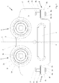
- Figures 1 to 6 show a preferred embodiment of a tarpaulin suspension device 1, in which a flat or planar base plate 2 punched out of sheet steel carries two support rollers 3 which are intended to be displaced horizontally in the plane of the two support rollers 3 in a corresponding track of a longitudinal member L. Furthermore, a connection device designed as an elongated hole 4 for a tarpaulin P is recessed in the base plate, the two ends of which are rounded and which furthermore has inwardly rounded edges between a front side 2v and a rear side 2h of the base plate 2.
- a belt can be passed through the elongated hole 4, which belt is sewn to the tarpaulin P, which is designed as a side tarpaulin, so that the tarpaulin suspension device 1 as a whole hangs the tarpaulin P on the longitudinal beam L.
- this is a plurality of Tarpaulin hanging devices 1 connected to the tarpaulin P and hung in the side member.
- another suspension element can also be considered, for example if a stiff part similar to a stanchion is arranged in the tarpaulin.
- a square opening 5 and a round opening 6 are cut out in the base plate, which on a plane E bisecting the base plate 2 into a left half and a right half ( Fig. 1 ) lie.
- the tarpaulin suspension device 1 is constructed with mirror symmetry with respect to this plane E.
- the edge of the base plate 2 is designed with radii at the corners and has a sufficient material distance from all openings 4, 5, 6 to the edge in order to avoid weak points.
- the base plate 2 can be roughly circumscribed by a rectangle lying on the long side, with an approximately square field 2e being cut out in each of the two lower corners of the rectangle.
- a guide roller 8 is mounted in each case, both of which are supported against an outward-facing guide track of the longitudinal member L.
- the two guide rollers 8 lie in a common horizontal plane which assumes a right angle to the vertical plane in which the support rollers 3 lie.
- a groove 2n penetrating the thickness of the base plate 2 is formed in the base plate 2 and cuts into the lower narrow side 2s.
- the region of the groove 2n adjoining the lower narrow side 2s has an insertion bevel designed in the manner of a bevel in order to facilitate the insertion of a bearing journal 8z of the guide roller 8.
- the bearing pin 8z is pressed or welded into the groove 2n of the base plate 2, in the case of the pressing in by a weld can provide a further safeguard. It can be seen that the thickness of the peg 8z is greater than the thickness of the base plate 2, so that the peg 8z protrudes beyond the base plate both on the front side 2v and on the rear side 2h.
- the bearing pin 8z protrudes a bit more on the front side than on the rear side 2h.
- the width of the bearing pin 8z is adapted to the width of the groove 2n, so that the bearing pin 8z is received essentially without play, possibly even in a clamping manner in the groove 2n.
- the bearing journal 8z is made of steel, so that it can be welded to the material of the base plate 2. It is possible that the areas of the bearing pin 8z that protrude from the groove 2n protrude laterally over the front 2v and / or the rear 2h of the base plate 2 and thus an additional clamping in the manner of a flange on the two flat sides of the base plate 2 or T-piece.
- the same material as the bearing pin 8z is provided with a washer-like washer 8s forming a collar, from the center of which a bolt-like cylindrical section 8b of the bearing pin 8z protrudes axially, which has a perforated washer 8k made of plastic and having a central bore who takes on the leadership role and stores.
- the perforated disk 8k of the guide roller 8 is then fixed with a snap ring 8r on the cylindrical bearing bolt 8b or a circumferential groove formed therein and secured against movement along the bolt 8b.
- a ball bearing can also be provided in which the inner bearing part would possibly be made in one piece with the pin 8z, so that the outer bearing part, for example made of metal, the rolling would make up part of role 8.
- the guide rollers 8 due to the rigid attachment of the bearing pins 8z to the base plate 2, the guide rollers 8 have practically no tolerance with respect to the base plate 2, so that by introducing a force into the tarpaulin suspension device 1, for example by pulling on the tarpaulin P, there is no danger consists in that the guide rollers 8 recede and the base plate 2 works its way into the longitudinal beam L.
- a modified embodiment of a preferred tarpaulin suspension device 1 ' is shown, with the same reference numerals as in the embodiment according to FIG Figures 1 to 6 designate the same or structurally comparable parts.
- the tarpaulin suspension device 1 ' is approximately in the horizontal plane dividing the elongated hole 4 into two vertical halves bent backwards by an angle of about 25 °, so that the lower edge of the elongated hole 4 is no longer aligned with the upper one Section 2o of the base plate 2 is aligned.
- the lower section 2u of the base plate 2 is angled relative to the upper section 2o of the base plate 2.
- the belt passed through the elongated hole 4 and the tarpaulin P bearing on it causes a moment on the base plate 2 around the plane in which the underside of the support rollers 3 rest on the corresponding path of the longitudinal beam L, with the result that the guide rollers 8 are pressed against the guide surface of the side member L by this moment.
- the area to which the guide rollers 8 are connected still belongs to the upper section 2o of the base plate, so that the The lower narrow side 2s of the base plate 2 further enables the guide roller 8 to be arranged perpendicular to the support roller 3.
- the base plate is to be folded in a higher area, it is possible to insert the bearing pin 8z in the groove 2n at an angle such that the guide roller 8 continues to lie in a horizontal plane. It is also possible to make the plastic part 8k of the guide roller 8 conical in order to compensate for the angle.
- Fig. 9 a vertical cross-section through the roller 8 and the associated part of the base plate 2 is shown (the same design for both embodiments), in which it can be seen that the bearing pin 8z, the washer 8s and the bolt 8b are designed as a one-piece part, and that the Bearing pin 8z not completely reached the bottom of the groove 2n. It can be seen that the center of the bolt 8b is slightly offset from the center plane of the base plate 2 in the direction of the front side 2v of the base plate 2, and that the diameter of the plastic part 8k is more than twice the diameter of the cylindrical bolt 8b. It can also be seen that no further parts are required for the guide roller 8.
- Fig. 8 shows a vertical cross section through the tarpaulin suspension device 1 ', which passes through the center of one of the support rollers 3.
- the guide roller 8 remains in the horizontal plane, while the lower section 2u of the base plate 2 including the lower part of the elongated hole 4 is bent backwards.
- the support roller 3 is screwed to the base plate 2 (the same in both exemplary embodiments).
- a screw 9 with a head 9k and a screw shaft 9s is provided which has an external thread 9g, the shaft-side flange of the head 9k resting against the rear side 2h of the base plate 2.
- the shaft 9s is adapted to the diameter of a bore 2b in the base plate and is thus held in the base plate 2 without play.
- the hole 2b is present (not shown) designed as a square hole, while the section of the shaft 9s penetrating the square hole is designed as a complementary square profile, so that the two interlocking parts form an anti-twist device.
- the guide roller 3 comprises an inner ring 3i and an outer ring 3a, onto which a rounded plastic profile 3k is applied.
- the rounded profile can, however, also be made of metal if this results in better running properties with the material of the longitudinal members L, which is usually made of aluminum.
- a ring of rolling elements 3w designed as balls allows the outer ring 3a to rotate relative to the inner ring 3i, with corresponding spherical circumferential grooves being provided in the outer ring 3a and inner ring 3i for this purpose.
- the rolling elements 3w are separated from one another by a rolling element support ring 3t, which at the same time conceals the forward-facing end face between the outer ring 3a and the inner ring 3i.
- a screen 3b is provided, which prevents the penetration of impurities and the like.
- the inner ring 3i is more than twice as wide as the outer ring 3a, and is elongated in the manner of a sleeve and has a central bore 3c.
- the central bore is at least partially equipped with an internal thread 3g into which the external thread 9g of the screw bolt 9 can be screwed.
- a hexagon 3s is formed, which serves as an attachment or receptacle for a tool.
- another hexagon or a slot is formed on the rearward-facing area of the screw bolt 9, which also serves as a receptacle for a tool if the bore 2b and the section of the shaft 9s penetrating it are not designed as a complementary square profile.
- the head 9k and the inner ring 3i have a diameter which makes it possible to cover the surface of the hole 2b, which is designed as a square hole, so that water or impurities cannot penetrate.
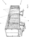
- FIG. 11 shows a view of a tarpaulin structure A which is building over a loading area F of a semi-trailer S.
- the tarpaulin structure A contains longitudinal beams L supported against the loading area F via stanchions R, to which a sliding roof D is connected.
- About tarpaulin suspension devices 1, which are in Fig. 10 are covered by a part of the roof tarpaulin and are therefore not visible, the side tarpaulin P is connected to a chamber K of the side member L ( Fig. 11 ), which allows tilting around the support rollers 3 on the bottom of the chamber K in such a way that the lower end of the tarpaulin suspension device 1 is pivoted outward.
- Fig. 11 One recognizes in Fig. 11 that the guide roller 8 rests against a guide track B of the longitudinal member L and thus ensures that the tarpaulin suspension device 1 does not rub against the longitudinal member L even when the tarpaulin P is released. In this way, the tarpaulin P is not rubbed against the longitudinal beam L either.
- the belt G which connects the side tarpaulin P to the tarpaulin suspension device 1, can also be seen. If the tarpaulin P is pulled in order to open or close it, the support rollers 3 roll along the bottom of the chamber K, while the guide rollers 8 roll on the outward-facing boundary B of the longitudinal beam L.
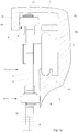
- Fig. 12 shows a further embodiment of a tarpaulin suspension device 1 ', in which the same parts or comparable parts as in the previous embodiment are denoted by the same reference numerals, so that only the differences will be discussed here.
- the longitudinal support 11 ' has a modified configuration in which the support roller 3 is guided in a track K1 provided in the chamber K, which supports the support roller 3 on both sides.
- the chamber K has a outwardly directed leg K2, which is arranged above the guide roller 3 and which prevents the tarpaulin hanging device 1 'from lifting out of the track K1.
- the outwardly directed surface K3 of the chamber K connecting the track K1 and the leg k2 is at a distance from the support rollers 3 so that the tarpaulin suspension device 1 'can be pivoted within the track K1.
- the longitudinal beam L ' has a further chamber J, the upper web J1 of which projects beyond the tarpaulin suspension device 1' and from which a downwardly folded area J2 projects, which provides a further guide track B1.
- a further guide roller 8 ' is connected to the upper edge of the base plate 2, comparable to the guide roller 8, a further guide roller 8' being provided opposite the guide roller 8, the outer circumference of the further guide roller 8 'rolling on the guide track B1. This creates an additional support which relieves the load on the guide roller 8 and therefore ensures an increased service life of the tarpaulin suspension device 1 '.
- the further guide rollers 8 ′ are connected to the base plate 2 in the same way as the guide rollers 8.
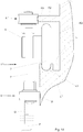
- Fig. 13 shows a further embodiment of a tarpaulin suspension device 1 ′′, in which the same reference numerals as in the embodiment according to FIG Fig. 12 show the same or structurally comparable parts.
- the geometry of the side member L " Fig. 13 is changed here, since the further guide roller 8 'and the support roller 3 run in the same chamber K, that is, the web K2 from Fig. 12 is omitted, so that overall a more compact, lower overall height of the chamber K is achieved.
- the support roller 3 is in turn guided in a track K1, while the outer circumference of the Guide roller 8 'I rolls on the guide track B1 of the chamber K.
- the height of the chamber K is dimensioned so that the tarpaulin suspension device 1 "can be pivoted in the track K1, but cannot be lifted upwards; for this purpose, the underside of the leg K4 is dimensioned so low that the upper end of the guide roller 8 'or .
- FIG. 13 Another special feature of the embodiment according to. Fig. 13 consists in that the guide roller 8 'is mounted on a pin which protrudes from the edge of the base plate 2 and is formed in one piece and in one piece with the base plate 2 and which was rounded off before the actual roller was put on. As a result, it is not necessary to insert a separate bolt into a recess in the base plate 2 or to drive it into it or to weld it, so that the manufacture is simplified and the stability of the tarpaulin suspension device 1 ′′ is increased.
- Fig. 14 shows a further embodiment of a tarpaulin suspension device 1 "', which can be displaced in a longitudinal beam L"', in which the same structurally comparable parts as in FIG Fig. 11 are explained with the same reference numerals.
- the tarpaulin suspension device 1 "' is very compact.
- the special feature of the tarpaulin suspension device 1"' is that the further guide roller 8 "'has a concave outer circumference as in FIG Fig. 14 which enables the further guide roller 8 '''to be supported on the outwardly facing edge of the leg K2 forming a guide track B3. This relieves the load on the guide roller 8, with the further guide roller 8'''' each each of the two guide rollers 8 is connected opposite to the base plate 2.
- Fig. 15 shows a further embodiment of a tarpaulin suspension device 1 ′′ ′′, in which the same reference numerals as in FIG Fig. 13 describe the same or structurally comparable parts.
- the guide roller 8 ′′ ′′ is guided in a modified profile of a longitudinal beam L ′′ ′′ which has only one chamber K with a track K1, the base plate 2 having a guide roller 8 ′′ ′′ above the level of the connection of the support rollers 3 , which is arranged approximately in the middle between the two support rollers 3 and which is quite small so that it can be arranged so deep that it protrudes beyond the plane in which the support rollers 3 are located over the upper edge of the base plate 2.
- the circumference of the guide roller 8 ′′ ′′ rolls against the guide track B2, which rolls on a leg J2 of the chamber K.
- the tarpaulin suspension device 1 ′′ ′′ with its support rollers 3 can pivot well in the track K1, the guide roller 8 ′′ ′′ allowing the side tarpaulin to pivot outward due to its contact with the guide track B2, but not allow the tarpaulin to pivot inward.
- a shoulder K3a is provided on the outwardly facing surface of the chamber K, against which the support rollers 3 abut in the event of pivoting, so that the maximum angle is advantageously limited as a result.
- the leg K4 prevents the tarpaulin suspension device 1 'from being lifted out, with the support rollers 3 making it impossible to lift it upwards.
- the special feature of the embodiment according to. Fig. 15 is that only one guide roller 8 ′′ ′′ is connected to the tarpaulin suspension device 1 ′′ ′′, since the support rollers 3 are already somewhat laterally supported by the track K1 and the moments that occur are therefore low.
- the guide roller is designed with a perforated disc 8k made of plastic as a roller member or as a rotatable part of the guide roller 8.
- a perforated disc made of metal can also be provided, in which case a bushing then expediently improves the friction properties on the bolt 8b and disc 8s.
- a bushing can for example be formed from Teflon in the manner of a collar bushing.
- the base plate is made of steel. It goes without saying that the base plate can also be made from other alloys or materials, in particular from plastic or a metal-plastic composite. If the base plate is formed from a plastic that can also be reinforced with glass fiber or aramid fiber, it is easily possible to provide the grooves 2n into which the bearing pin 8z of the roller 8 is machined without machining. It is then also possible to produce the bearing pin 8z in one piece with the base plate 2, so that only the perforated disk 8k has to be attached and secured. It is even possible to manufacture the perforated disk 8k in one piece with the manufacture from plastic.
- the guide rollers 8 are arranged in a plane perpendicular to the support rollers 3 and in a plane perpendicular to the extension of the base plate 2, but at least its upper section 2o. It goes without saying that the guide rollers 8 can also assume an angle to this in order to compensate for the elastic deformation, in particular when the tarpaulin P is opened and closed.
- a guide roller 8 is provided in each of the two corners 2e of the base plate 2. It goes without saying that only one guide roller 8 can be provided on the base plate 2, or that only in a guide roller 8 can be arranged in one of the two corners 2e. It is also possible to provide further guide rollers in addition to the two guide rollers 8 if, for example, further guide surfaces of the longitudinal member L enable support.
- the guide rollers 8 are arranged approximately in alignment with the extension of the elongated hole 4.
- the exact positioning of the plane of the guide rollers 8 or the plastic perforated disk 8k results from the position of the associated guide surface on the longitudinal member L. It is possible to arrange the guide rollers 8 further down, based on the elongated hole 4, i.e. also below the elongated hole 4 or below the corner 2e which is then not or not completely recessed.
- the guide roller 8 is inserted into a groove 2n in the base plate. It goes without saying that the guide roller 8 can also be arranged on a projection that protrudes from the lower edge or the lower narrow side 2s of the base plate 2 if the protruding section is sufficiently rounded to support the plastic perforated disk 8k rotatably. Alternatively, instead of rounding, a round bearing with a polygonal hole can be attached to the protruding section.
- the bearing pin also has a position in relation to the plane of the base plate Can include angles.
- the angle can also be up to 135 ° and in particular 90 °. If the bearing pin is formed from the base plate 2 itself, it can be bent - also before or after the rounding. It is thus also possible, for example, to punch a pin free from the base plate and then bend it vertically, with the result that the support rollers 3 can be connected to this pin.
Landscapes
- Engineering & Computer Science (AREA)
- Mechanical Engineering (AREA)
- Tents Or Canopies (AREA)
- Handcart (AREA)
- Road Paving Machines (AREA)
- Storage Of Web-Like Or Filamentary Materials (AREA)
Priority Applications (1)
| Application Number | Priority Date | Filing Date | Title |
|---|---|---|---|
| PL16788010T PL3344480T3 (pl) | 2015-09-01 | 2016-09-01 | Urządzenie do zawieszania plandeki |
Applications Claiming Priority (2)
| Application Number | Priority Date | Filing Date | Title |
|---|---|---|---|
| DE202015006044.7U DE202015006044U1 (de) | 2015-09-01 | 2015-09-01 | Planenaufhängvorrichtung |
| PCT/DE2016/100400 WO2017036463A1 (de) | 2015-09-01 | 2016-09-01 | Planenaufhängvorrichtung |
Publications (2)
| Publication Number | Publication Date |
|---|---|
| EP3344480A1 EP3344480A1 (de) | 2018-07-11 |
| EP3344480B1 true EP3344480B1 (de) | 2021-06-16 |
Family
ID=54481849
Family Applications (1)
| Application Number | Title | Priority Date | Filing Date |
|---|---|---|---|
| EP16788010.3A Active EP3344480B1 (de) | 2015-09-01 | 2016-09-01 | Planenaufhängvorrichtung |
Country Status (7)
| Country | Link |
|---|---|
| US (1) | US10596884B2 (pl) |
| EP (1) | EP3344480B1 (pl) |
| CN (1) | CN108025626B (pl) |
| AU (1) | AU2016315296B2 (pl) |
| DE (2) | DE202015006044U1 (pl) |
| PL (1) | PL3344480T3 (pl) |
| WO (1) | WO2017036463A1 (pl) |
Families Citing this family (13)
| Publication number | Priority date | Publication date | Assignee | Title |
|---|---|---|---|---|
| DE102017106126A1 (de) | 2017-03-22 | 2018-09-27 | Schmitz Cargobull Ag | Aufbau eines Nutzfahrzeugs für den Kleidertransport |
| DE102017107583B4 (de) * | 2017-04-07 | 2024-11-21 | European Trailer Systems Gmbh | Rolle |
| ES1191083Y (es) * | 2017-08-02 | 2017-11-29 | Klein Iberica S A U | Dispositivo de sujecion de hojas de vidrio para puertas correderas |
| JP7083668B2 (ja) * | 2018-03-15 | 2022-06-13 | Ykk Ap株式会社 | 戸車、戸体及び建具 |
| RU197688U1 (ru) * | 2019-12-18 | 2020-05-21 | Владимир Владимирович Иванов | Съемное многооборотное устройство для перевозки грузов на универсальных вагонах-платформах |
| EP3859108B1 (en) * | 2020-01-31 | 2024-04-03 | Ningbo Geely Automobile Research & Development Co. Ltd. | Roller assembly for a sliding vehicle door |
| DE102021108772B3 (de) | 2021-04-08 | 2022-09-15 | Helmut Fliegl | Planenroller zur verschiebbaren lagerung einer plane |
| USD1038743S1 (en) * | 2021-12-27 | 2024-08-13 | Klein Iberica, S.A.U. | Holding device for sliding doors |
| DE202022102312U1 (de) | 2022-04-28 | 2022-05-19 | European Trailer Systems Gmbh | Öffenbares Seitenplanenwandsystem |
| EP4514635A1 (de) | 2022-04-28 | 2025-03-05 | European Trailer Systems GmbH | Öffenbares seitenplanenwandsystem |
| DE102022110441B4 (de) | 2022-04-28 | 2025-11-27 | European Trailer Systems Gmbh | Schieberunge und öffenbares Seitenplanenwandsystem |
| DE102022110440B3 (de) | 2022-04-28 | 2023-10-19 | European Trailer Systems Gmbh | Öffenbares Seitenplanenwandsystem und Schieberunge |
| DE102022110438B4 (de) | 2022-04-28 | 2025-05-28 | European Trailer Systems Gmbh | Öffenbares Seitenplanenwandsystem |
Citations (3)
| Publication number | Priority date | Publication date | Assignee | Title |
|---|---|---|---|---|
| WO2009003218A1 (en) * | 2007-06-29 | 2009-01-08 | Barker Trailers Pty. Ltd. | Curtain-sided trailer and roller assembly for side curtain assemblies |
| DE202012003235U1 (de) * | 2012-03-31 | 2013-07-01 | Edscha Trailer Systems Gmbh | Verdeckgestell für einen Planenaufbau |
| DE202014000805U1 (de) * | 2014-01-31 | 2014-02-17 | European Trailer Systems Gmbh | Planenaufhängvorrichtung |
Family Cites Families (13)
| Publication number | Priority date | Publication date | Assignee | Title |
|---|---|---|---|---|
| GB2071582B (en) * | 1980-01-31 | 1984-12-05 | Trende Transport Design Ltd | Curtain-sided vehicle bodies |
| IT1277184B1 (it) * | 1995-04-05 | 1997-11-05 | Spring Di Croce Mattia Celso & | Guida a piu' corsie di scorrimento per la movimentazione in apertura-chiusura dei teloni laterali delle centine portanti |
| ATE203958T1 (de) | 1997-06-18 | 2001-08-15 | Edscha Lkw Schiebeverdeck Gmbh | Verschiebbare seitenplane für nutzfahrzeuge |
| DE29815722U1 (de) * | 1998-09-01 | 2000-01-13 | Edscha LKW-Schiebeverdecke GmbH, 94491 Hengersberg | Faltbarer Planenaufbau für Fahrzeugaufbauten und Container |
| DE19839824A1 (de) * | 1998-09-01 | 2000-03-02 | Edscha Lkw Schiebeverdeck Gmbh | Seitenplanenaufhängung an Verdecken für Nutzfahrzeuge |
| DE19855653A1 (de) * | 1998-12-03 | 2000-06-08 | Edscha Lkw Schiebeverdeck Gmbh | Spiegelausbildung für zusammenschiebbare Verdecke an Fahrzeugaufbauten oder Containern |
| US7975633B2 (en) * | 2008-06-27 | 2011-07-12 | Miller Weldmaster Corporation | Bi-directional seaming machine |
| DE202009002621U1 (de) | 2009-02-25 | 2009-07-16 | Vbg Group Truck Equipment Gmbh | Schiebeverdeck |
| BE1019270A3 (nl) | 2010-04-02 | 2012-05-08 | Versus Invest | Systeem voor het ophangen van een zeil. |
| BE1021442B1 (nl) | 2012-09-17 | 2015-11-20 | Versus-Invest | Bevestigingssysteem voor een zeil |
| DE102013201003A1 (de) | 2013-01-23 | 2014-08-07 | Zf Friedrichshafen Ag | Längsgurt für Schiebeverdeckstruktur und Schiebeverdeckstruktur |
| DE102013201005A1 (de) | 2013-01-23 | 2014-08-07 | Zf Friedrichshafen Ag | Seitenrollenwagen und Führungsgurt mit Schiene für eine Schiebeverdeckstruktur eines Fahrzeugaufbaus oder eines Containers |
| DE102013014629B4 (de) | 2013-09-04 | 2019-12-05 | Fahrzeugwerk Bernard Krone Gmbh | Nutzfahrzeugaufbau mit einer Schiebeplane |
-
2015
- 2015-09-01 DE DE202015006044.7U patent/DE202015006044U1/de not_active Expired - Lifetime
-
2016
- 2016-09-01 DE DE102016116390.2A patent/DE102016116390A1/de not_active Withdrawn
- 2016-09-01 US US15/755,574 patent/US10596884B2/en active Active
- 2016-09-01 EP EP16788010.3A patent/EP3344480B1/de active Active
- 2016-09-01 CN CN201680049974.6A patent/CN108025626B/zh active Active
- 2016-09-01 AU AU2016315296A patent/AU2016315296B2/en active Active
- 2016-09-01 PL PL16788010T patent/PL3344480T3/pl unknown
- 2016-09-01 WO PCT/DE2016/100400 patent/WO2017036463A1/de not_active Ceased
Patent Citations (3)
| Publication number | Priority date | Publication date | Assignee | Title |
|---|---|---|---|---|
| WO2009003218A1 (en) * | 2007-06-29 | 2009-01-08 | Barker Trailers Pty. Ltd. | Curtain-sided trailer and roller assembly for side curtain assemblies |
| DE202012003235U1 (de) * | 2012-03-31 | 2013-07-01 | Edscha Trailer Systems Gmbh | Verdeckgestell für einen Planenaufbau |
| DE202014000805U1 (de) * | 2014-01-31 | 2014-02-17 | European Trailer Systems Gmbh | Planenaufhängvorrichtung |
Also Published As
| Publication number | Publication date |
|---|---|
| DE202015006044U1 (de) | 2015-10-26 |
| CN108025626A (zh) | 2018-05-11 |
| AU2016315296A1 (en) | 2018-03-22 |
| EP3344480A1 (de) | 2018-07-11 |
| CN108025626B (zh) | 2021-08-10 |
| US10596884B2 (en) | 2020-03-24 |
| WO2017036463A1 (de) | 2017-03-09 |
| AU2016315296B2 (en) | 2021-01-14 |
| US20180354350A1 (en) | 2018-12-13 |
| PL3344480T3 (pl) | 2021-11-22 |
| DE102016116390A1 (de) | 2017-03-02 |
Similar Documents
| Publication | Publication Date | Title |
|---|---|---|
| EP3344480B1 (de) | Planenaufhängvorrichtung | |
| EP0254977B1 (de) | Abstreifvorrichtung für den Rücklaufbereich von Förderbändern | |
| DE69923038T2 (de) | Verbindungsvorrichtung für metallische Gitterelemente | |
| EP0060498B1 (de) | Vorrichtung zum Verbinden von zwei stumpf gestossenen Bewehrungsstäben mittels einer Muffe | |
| DE1425143A1 (de) | Rollenlagerung | |
| DE3144258A1 (de) | Sieb-spann- und druckrahmen | |
| DE10164598B4 (de) | Anschlussvorrichtung zum Anschließen von Anschlag- oder Verzurrmitteln | |
| DE102015001092A1 (de) | Planenaufhängvorrichtung | |
| EP0921328B1 (de) | Lagerbuchse mit Mittelbund sowie deren Verwendung und Herstellungsverfahren | |
| DE3601127C2 (de) | Lasthängevorrichtung mit verbessertem Hakenbolzen | |
| EP3175066B1 (de) | Rolle | |
| DE102016103171B4 (de) | Aufbau für ein Nutzfahrzeug | |
| DE202004012138U1 (de) | Stempelkopflagerung zwischen Kappe und Stempel eines Schildausbaugestells | |
| DE20321780U1 (de) | Förderband mit in Lagergehäusen pendelbar aufgenommenen Drehlagern | |
| DE3813088C2 (pl) | ||
| EP2391790A1 (de) | Beschlaganordnung für lichtkuppel | |
| DE60003166T2 (de) | Kippvorrichtung | |
| DE10343539B4 (de) | Förderband mit einer Antriebseinheit | |
| DE69700991T2 (de) | Federringe | |
| EP0723058A2 (de) | Bremse, insbesondere für einen Oberlichtflügel | |
| DE60216760T2 (de) | Kupplungskonstruktion und verfahren zur verbindung und verriegelung der walzen einer presse mit verlängerter presszone | |
| DE20215155U1 (de) | Gelenkige Schienenverbindung für Schienenstöße von Profillaufschienen | |
| EP1882554B1 (de) | Vorrichtung zum Verstellen von Positionierungsstiften zur Lagerfixierung von Werkstücken auf Werkstückträgern | |
| DE102009040302B4 (de) | Exzenterlager | |
| DE29803330U1 (de) | Hubvorrichtung |
Legal Events
| Date | Code | Title | Description |
|---|---|---|---|
| STAA | Information on the status of an ep patent application or granted ep patent |
Free format text: STATUS: UNKNOWN |
|
| STAA | Information on the status of an ep patent application or granted ep patent |
Free format text: STATUS: THE INTERNATIONAL PUBLICATION HAS BEEN MADE |
|
| PUAI | Public reference made under article 153(3) epc to a published international application that has entered the european phase |
Free format text: ORIGINAL CODE: 0009012 |
|
| STAA | Information on the status of an ep patent application or granted ep patent |
Free format text: STATUS: REQUEST FOR EXAMINATION WAS MADE |
|
| 17P | Request for examination filed |
Effective date: 20180209 |
|
| AK | Designated contracting states |
Kind code of ref document: A1 Designated state(s): AL AT BE BG CH CY CZ DE DK EE ES FI FR GB GR HR HU IE IS IT LI LT LU LV MC MK MT NL NO PL PT RO RS SE SI SK SM TR |
|
| AX | Request for extension of the european patent |
Extension state: BA ME |
|
| DAV | Request for validation of the european patent (deleted) | ||
| DAX | Request for extension of the european patent (deleted) | ||
| STAA | Information on the status of an ep patent application or granted ep patent |
Free format text: STATUS: EXAMINATION IS IN PROGRESS |
|
| 17Q | First examination report despatched |
Effective date: 20200305 |
|
| GRAP | Despatch of communication of intention to grant a patent |
Free format text: ORIGINAL CODE: EPIDOSNIGR1 |
|
| STAA | Information on the status of an ep patent application or granted ep patent |
Free format text: STATUS: GRANT OF PATENT IS INTENDED |
|
| INTG | Intention to grant announced |
Effective date: 20210303 |
|
| GRAS | Grant fee paid |
Free format text: ORIGINAL CODE: EPIDOSNIGR3 |
|
| GRAA | (expected) grant |
Free format text: ORIGINAL CODE: 0009210 |
|
| STAA | Information on the status of an ep patent application or granted ep patent |
Free format text: STATUS: THE PATENT HAS BEEN GRANTED |
|
| AK | Designated contracting states |
Kind code of ref document: B1 Designated state(s): AL AT BE BG CH CY CZ DE DK EE ES FI FR GB GR HR HU IE IS IT LI LT LU LV MC MK MT NL NO PL PT RO RS SE SI SK SM TR |
|
| REG | Reference to a national code |
Ref country code: GB Ref legal event code: FG4D Free format text: NOT ENGLISH |
|
| REG | Reference to a national code |
Ref country code: CH Ref legal event code: EP |
|
| REG | Reference to a national code |
Ref country code: DE Ref legal event code: R096 Ref document number: 502016013245 Country of ref document: DE |
|
| REG | Reference to a national code |
Ref country code: AT Ref legal event code: REF Ref document number: 1402043 Country of ref document: AT Kind code of ref document: T Effective date: 20210715 |
|
| REG | Reference to a national code |
Ref country code: IE Ref legal event code: FG4D Free format text: LANGUAGE OF EP DOCUMENT: GERMAN |
|
| REG | Reference to a national code |
Ref country code: NL Ref legal event code: FP |
|
| REG | Reference to a national code |
Ref country code: LT Ref legal event code: MG9D |
|
| PG25 | Lapsed in a contracting state [announced via postgrant information from national office to epo] |
Ref country code: BG Free format text: LAPSE BECAUSE OF FAILURE TO SUBMIT A TRANSLATION OF THE DESCRIPTION OR TO PAY THE FEE WITHIN THE PRESCRIBED TIME-LIMIT Effective date: 20210916 Ref country code: HR Free format text: LAPSE BECAUSE OF FAILURE TO SUBMIT A TRANSLATION OF THE DESCRIPTION OR TO PAY THE FEE WITHIN THE PRESCRIBED TIME-LIMIT Effective date: 20210616 Ref country code: FI Free format text: LAPSE BECAUSE OF FAILURE TO SUBMIT A TRANSLATION OF THE DESCRIPTION OR TO PAY THE FEE WITHIN THE PRESCRIBED TIME-LIMIT Effective date: 20210616 Ref country code: LT Free format text: LAPSE BECAUSE OF FAILURE TO SUBMIT A TRANSLATION OF THE DESCRIPTION OR TO PAY THE FEE WITHIN THE PRESCRIBED TIME-LIMIT Effective date: 20210616 |
|
| PG25 | Lapsed in a contracting state [announced via postgrant information from national office to epo] |
Ref country code: GR Free format text: LAPSE BECAUSE OF FAILURE TO SUBMIT A TRANSLATION OF THE DESCRIPTION OR TO PAY THE FEE WITHIN THE PRESCRIBED TIME-LIMIT Effective date: 20210917 Ref country code: LV Free format text: LAPSE BECAUSE OF FAILURE TO SUBMIT A TRANSLATION OF THE DESCRIPTION OR TO PAY THE FEE WITHIN THE PRESCRIBED TIME-LIMIT Effective date: 20210616 Ref country code: NO Free format text: LAPSE BECAUSE OF FAILURE TO SUBMIT A TRANSLATION OF THE DESCRIPTION OR TO PAY THE FEE WITHIN THE PRESCRIBED TIME-LIMIT Effective date: 20210916 Ref country code: RS Free format text: LAPSE BECAUSE OF FAILURE TO SUBMIT A TRANSLATION OF THE DESCRIPTION OR TO PAY THE FEE WITHIN THE PRESCRIBED TIME-LIMIT Effective date: 20210616 Ref country code: SE Free format text: LAPSE BECAUSE OF FAILURE TO SUBMIT A TRANSLATION OF THE DESCRIPTION OR TO PAY THE FEE WITHIN THE PRESCRIBED TIME-LIMIT Effective date: 20210616 |
|
| PG25 | Lapsed in a contracting state [announced via postgrant information from national office to epo] |
Ref country code: SM Free format text: LAPSE BECAUSE OF FAILURE TO SUBMIT A TRANSLATION OF THE DESCRIPTION OR TO PAY THE FEE WITHIN THE PRESCRIBED TIME-LIMIT Effective date: 20210616 Ref country code: SK Free format text: LAPSE BECAUSE OF FAILURE TO SUBMIT A TRANSLATION OF THE DESCRIPTION OR TO PAY THE FEE WITHIN THE PRESCRIBED TIME-LIMIT Effective date: 20210616 Ref country code: EE Free format text: LAPSE BECAUSE OF FAILURE TO SUBMIT A TRANSLATION OF THE DESCRIPTION OR TO PAY THE FEE WITHIN THE PRESCRIBED TIME-LIMIT Effective date: 20210616 Ref country code: RO Free format text: LAPSE BECAUSE OF FAILURE TO SUBMIT A TRANSLATION OF THE DESCRIPTION OR TO PAY THE FEE WITHIN THE PRESCRIBED TIME-LIMIT Effective date: 20210616 Ref country code: PT Free format text: LAPSE BECAUSE OF FAILURE TO SUBMIT A TRANSLATION OF THE DESCRIPTION OR TO PAY THE FEE WITHIN THE PRESCRIBED TIME-LIMIT Effective date: 20211018 Ref country code: ES Free format text: LAPSE BECAUSE OF FAILURE TO SUBMIT A TRANSLATION OF THE DESCRIPTION OR TO PAY THE FEE WITHIN THE PRESCRIBED TIME-LIMIT Effective date: 20210616 |
|
| REG | Reference to a national code |
Ref country code: DE Ref legal event code: R097 Ref document number: 502016013245 Country of ref document: DE |
|
| PLBE | No opposition filed within time limit |
Free format text: ORIGINAL CODE: 0009261 |
|
| STAA | Information on the status of an ep patent application or granted ep patent |
Free format text: STATUS: NO OPPOSITION FILED WITHIN TIME LIMIT |
|
| PG25 | Lapsed in a contracting state [announced via postgrant information from national office to epo] |
Ref country code: DK Free format text: LAPSE BECAUSE OF FAILURE TO SUBMIT A TRANSLATION OF THE DESCRIPTION OR TO PAY THE FEE WITHIN THE PRESCRIBED TIME-LIMIT Effective date: 20210616 |
|
| REG | Reference to a national code |
Ref country code: CH Ref legal event code: PL |
|
| 26N | No opposition filed |
Effective date: 20220317 |
|
| GBPC | Gb: european patent ceased through non-payment of renewal fee |
Effective date: 20210916 |
|
| PG25 | Lapsed in a contracting state [announced via postgrant information from national office to epo] |
Ref country code: MC Free format text: LAPSE BECAUSE OF FAILURE TO SUBMIT A TRANSLATION OF THE DESCRIPTION OR TO PAY THE FEE WITHIN THE PRESCRIBED TIME-LIMIT Effective date: 20210616 Ref country code: AL Free format text: LAPSE BECAUSE OF FAILURE TO SUBMIT A TRANSLATION OF THE DESCRIPTION OR TO PAY THE FEE WITHIN THE PRESCRIBED TIME-LIMIT Effective date: 20210616 |
|
| PG25 | Lapsed in a contracting state [announced via postgrant information from national office to epo] |
Ref country code: LU Free format text: LAPSE BECAUSE OF NON-PAYMENT OF DUE FEES Effective date: 20210901 Ref country code: IE Free format text: LAPSE BECAUSE OF NON-PAYMENT OF DUE FEES Effective date: 20210901 Ref country code: GB Free format text: LAPSE BECAUSE OF NON-PAYMENT OF DUE FEES Effective date: 20210916 Ref country code: FR Free format text: LAPSE BECAUSE OF NON-PAYMENT OF DUE FEES Effective date: 20210930 |
|
| PG25 | Lapsed in a contracting state [announced via postgrant information from national office to epo] |
Ref country code: LI Free format text: LAPSE BECAUSE OF NON-PAYMENT OF DUE FEES Effective date: 20210930 Ref country code: CH Free format text: LAPSE BECAUSE OF NON-PAYMENT OF DUE FEES Effective date: 20210930 |
|
| REG | Reference to a national code |
Ref country code: AT Ref legal event code: MM01 Ref document number: 1402043 Country of ref document: AT Kind code of ref document: T Effective date: 20210901 |
|
| PG25 | Lapsed in a contracting state [announced via postgrant information from national office to epo] |
Ref country code: AT Free format text: LAPSE BECAUSE OF NON-PAYMENT OF DUE FEES Effective date: 20210901 |
|
| PG25 | Lapsed in a contracting state [announced via postgrant information from national office to epo] |
Ref country code: HU Free format text: LAPSE BECAUSE OF FAILURE TO SUBMIT A TRANSLATION OF THE DESCRIPTION OR TO PAY THE FEE WITHIN THE PRESCRIBED TIME-LIMIT; INVALID AB INITIO Effective date: 20160901 |
|
| PG25 | Lapsed in a contracting state [announced via postgrant information from national office to epo] |
Ref country code: CY Free format text: LAPSE BECAUSE OF FAILURE TO SUBMIT A TRANSLATION OF THE DESCRIPTION OR TO PAY THE FEE WITHIN THE PRESCRIBED TIME-LIMIT Effective date: 20210616 |
|
| PG25 | Lapsed in a contracting state [announced via postgrant information from national office to epo] |
Ref country code: MK Free format text: LAPSE BECAUSE OF FAILURE TO SUBMIT A TRANSLATION OF THE DESCRIPTION OR TO PAY THE FEE WITHIN THE PRESCRIBED TIME-LIMIT Effective date: 20210616 |
|
| PG25 | Lapsed in a contracting state [announced via postgrant information from national office to epo] |
Ref country code: MT Free format text: LAPSE BECAUSE OF FAILURE TO SUBMIT A TRANSLATION OF THE DESCRIPTION OR TO PAY THE FEE WITHIN THE PRESCRIBED TIME-LIMIT Effective date: 20210616 |
|
| PGFP | Annual fee paid to national office [announced via postgrant information from national office to epo] |
Ref country code: CZ Payment date: 20240826 Year of fee payment: 9 |
|
| PGFP | Annual fee paid to national office [announced via postgrant information from national office to epo] |
Ref country code: DE Payment date: 20250919 Year of fee payment: 10 |
|
| PGFP | Annual fee paid to national office [announced via postgrant information from national office to epo] |
Ref country code: PL Payment date: 20250820 Year of fee payment: 10 Ref country code: IT Payment date: 20250923 Year of fee payment: 10 Ref country code: TR Payment date: 20250825 Year of fee payment: 10 Ref country code: NL Payment date: 20250918 Year of fee payment: 10 |
|
| PGFP | Annual fee paid to national office [announced via postgrant information from national office to epo] |
Ref country code: BE Payment date: 20250918 Year of fee payment: 10 |
|
| PG25 | Lapsed in a contracting state [announced via postgrant information from national office to epo] |
Ref country code: CZ Free format text: LAPSE BECAUSE OF NON-PAYMENT OF DUE FEES Effective date: 20250901 |