EP3344405B1 - Produktionsanlage und verfahren zur herstellung von kfz-kennzeichenschildern - Google Patents
Produktionsanlage und verfahren zur herstellung von kfz-kennzeichenschildern Download PDFInfo
- Publication number
- EP3344405B1 EP3344405B1 EP16757592.7A EP16757592A EP3344405B1 EP 3344405 B1 EP3344405 B1 EP 3344405B1 EP 16757592 A EP16757592 A EP 16757592A EP 3344405 B1 EP3344405 B1 EP 3344405B1
- Authority
- EP
- European Patent Office
- Prior art keywords
- buffer
- conveying means
- production system
- hot stamping
- transfer device
- Prior art date
- Legal status (The legal status is an assumption and is not a legal conclusion. Google has not performed a legal analysis and makes no representation as to the accuracy of the status listed.)
- Active
Links
- 238000004519 manufacturing process Methods 0.000 title claims description 49
- 239000000872 buffer Substances 0.000 claims description 116
- 238000012546 transfer Methods 0.000 claims description 38
- 238000000034 method Methods 0.000 claims description 25
- 238000000151 deposition Methods 0.000 claims description 14
- 238000012432 intermediate storage Methods 0.000 claims description 5
- 238000010924 continuous production Methods 0.000 claims description 2
- 230000008021 deposition Effects 0.000 claims 11
- 239000003973 paint Substances 0.000 claims 1
- 238000004049 embossing Methods 0.000 description 48
- 238000003860 storage Methods 0.000 description 39
- 239000011888 foil Substances 0.000 description 18
- 238000006243 chemical reaction Methods 0.000 description 15
- 230000032258 transport Effects 0.000 description 11
- 230000008569 process Effects 0.000 description 9
- 230000008901 benefit Effects 0.000 description 6
- 239000000463 material Substances 0.000 description 5
- 238000013016 damping Methods 0.000 description 4
- 239000004033 plastic Substances 0.000 description 4
- 230000008859 change Effects 0.000 description 3
- 238000011161 development Methods 0.000 description 3
- 230000018109 developmental process Effects 0.000 description 3
- 238000013459 approach Methods 0.000 description 2
- 239000012876 carrier material Substances 0.000 description 2
- 238000004040 coloring Methods 0.000 description 2
- 230000007613 environmental effect Effects 0.000 description 2
- 230000007257 malfunction Effects 0.000 description 2
- 229910052751 metal Inorganic materials 0.000 description 2
- 239000002184 metal Substances 0.000 description 2
- 238000012544 monitoring process Methods 0.000 description 2
- 229920006311 Urethane elastomer Polymers 0.000 description 1
- 230000002411 adverse Effects 0.000 description 1
- 229910052782 aluminium Inorganic materials 0.000 description 1
- XAGFODPZIPBFFR-UHFFFAOYSA-N aluminium Chemical compound [Al] XAGFODPZIPBFFR-UHFFFAOYSA-N 0.000 description 1
- 230000004888 barrier function Effects 0.000 description 1
- 230000001413 cellular effect Effects 0.000 description 1
- 239000003086 colorant Substances 0.000 description 1
- 238000004891 communication Methods 0.000 description 1
- 230000001934 delay Effects 0.000 description 1
- 230000000694 effects Effects 0.000 description 1
- 229920001971 elastomer Polymers 0.000 description 1
- 239000000806 elastomer Substances 0.000 description 1
- 230000001788 irregular Effects 0.000 description 1
- 230000007774 longterm Effects 0.000 description 1
- 230000007246 mechanism Effects 0.000 description 1
- 238000004806 packaging method and process Methods 0.000 description 1
- 230000002093 peripheral effect Effects 0.000 description 1
- 239000002985 plastic film Substances 0.000 description 1
- 229920006255 plastic film Polymers 0.000 description 1
- 239000004810 polytetrafluoroethylene Substances 0.000 description 1
- 229920001343 polytetrafluoroethylene Polymers 0.000 description 1
- 238000011144 upstream manufacturing Methods 0.000 description 1
Images



Classifications
-
- B—PERFORMING OPERATIONS; TRANSPORTING
- B05—SPRAYING OR ATOMISING IN GENERAL; APPLYING FLUENT MATERIALS TO SURFACES, IN GENERAL
- B05C—APPARATUS FOR APPLYING FLUENT MATERIALS TO SURFACES, IN GENERAL
- B05C1/00—Apparatus in which liquid or other fluent material is applied to the surface of the work by contact with a member carrying the liquid or other fluent material, e.g. a porous member loaded with a liquid to be applied as a coating
- B05C1/02—Apparatus in which liquid or other fluent material is applied to the surface of the work by contact with a member carrying the liquid or other fluent material, e.g. a porous member loaded with a liquid to be applied as a coating for applying liquid or other fluent material to separate articles
- B05C1/027—Apparatus in which liquid or other fluent material is applied to the surface of the work by contact with a member carrying the liquid or other fluent material, e.g. a porous member loaded with a liquid to be applied as a coating for applying liquid or other fluent material to separate articles only at particular parts of the articles
-
- B—PERFORMING OPERATIONS; TRANSPORTING
- B44—DECORATIVE ARTS
- B44B—MACHINES, APPARATUS OR TOOLS FOR ARTISTIC WORK, e.g. FOR SCULPTURING, GUILLOCHING, CARVING, BRANDING, INLAYING
- B44B5/00—Machines or apparatus for embossing decorations or marks, e.g. embossing coins
- B44B5/0071—Machines or apparatus for embossing decorations or marks, e.g. embossing coins which simultaneously apply a decorative material
-
- B—PERFORMING OPERATIONS; TRANSPORTING
- B05—SPRAYING OR ATOMISING IN GENERAL; APPLYING FLUENT MATERIALS TO SURFACES, IN GENERAL
- B05C—APPARATUS FOR APPLYING FLUENT MATERIALS TO SURFACES, IN GENERAL
- B05C1/00—Apparatus in which liquid or other fluent material is applied to the surface of the work by contact with a member carrying the liquid or other fluent material, e.g. a porous member loaded with a liquid to be applied as a coating
- B05C1/04—Apparatus in which liquid or other fluent material is applied to the surface of the work by contact with a member carrying the liquid or other fluent material, e.g. a porous member loaded with a liquid to be applied as a coating for applying liquid or other fluent material to work of indefinite length
- B05C1/14—Apparatus in which liquid or other fluent material is applied to the surface of the work by contact with a member carrying the liquid or other fluent material, e.g. a porous member loaded with a liquid to be applied as a coating for applying liquid or other fluent material to work of indefinite length using a travelling band
-
- B—PERFORMING OPERATIONS; TRANSPORTING
- B21—MECHANICAL METAL-WORKING WITHOUT ESSENTIALLY REMOVING MATERIAL; PUNCHING METAL
- B21D—WORKING OR PROCESSING OF SHEET METAL OR METAL TUBES, RODS OR PROFILES WITHOUT ESSENTIALLY REMOVING MATERIAL; PUNCHING METAL
- B21D22/00—Shaping without cutting, by stamping, spinning, or deep-drawing
- B21D22/02—Stamping using rigid devices or tools
- B21D22/022—Stamping using rigid devices or tools by heating the blank or stamping associated with heat treatment
-
- B—PERFORMING OPERATIONS; TRANSPORTING
- B41—PRINTING; LINING MACHINES; TYPEWRITERS; STAMPS
- B41F—PRINTING MACHINES OR PRESSES
- B41F16/00—Transfer printing apparatus
- B41F16/0006—Transfer printing apparatus for printing from an inked or preprinted foil or band
- B41F16/002—Presses of the rotary type
- B41F16/0026—Presses of the rotary type with means for applying print under heat and pressure, e.g. using heat activable adhesive
-
- B—PERFORMING OPERATIONS; TRANSPORTING
- B41—PRINTING; LINING MACHINES; TYPEWRITERS; STAMPS
- B41F—PRINTING MACHINES OR PRESSES
- B41F16/00—Transfer printing apparatus
- B41F16/0006—Transfer printing apparatus for printing from an inked or preprinted foil or band
- B41F16/0073—Transfer printing apparatus for printing from an inked or preprinted foil or band with means for printing on specific materials or products
-
- B—PERFORMING OPERATIONS; TRANSPORTING
- B44—DECORATIVE ARTS
- B44B—MACHINES, APPARATUS OR TOOLS FOR ARTISTIC WORK, e.g. FOR SCULPTURING, GUILLOCHING, CARVING, BRANDING, INLAYING
- B44B5/00—Machines or apparatus for embossing decorations or marks, e.g. embossing coins
- B44B5/0004—Machines or apparatus for embossing decorations or marks, e.g. embossing coins characterised by the movement of the embossing tool(s), or the movement of the work, during the embossing operation
- B44B5/0009—Rotating embossing tools
-
- B—PERFORMING OPERATIONS; TRANSPORTING
- B44—DECORATIVE ARTS
- B44B—MACHINES, APPARATUS OR TOOLS FOR ARTISTIC WORK, e.g. FOR SCULPTURING, GUILLOCHING, CARVING, BRANDING, INLAYING
- B44B5/00—Machines or apparatus for embossing decorations or marks, e.g. embossing coins
- B44B5/009—Machines or apparatus for embossing decorations or marks, e.g. embossing coins by multi-step processes
-
- B—PERFORMING OPERATIONS; TRANSPORTING
- B44—DECORATIVE ARTS
- B44B—MACHINES, APPARATUS OR TOOLS FOR ARTISTIC WORK, e.g. FOR SCULPTURING, GUILLOCHING, CARVING, BRANDING, INLAYING
- B44B5/00—Machines or apparatus for embossing decorations or marks, e.g. embossing coins
- B44B5/02—Dies; Accessories
- B44B5/022—Devices for holding or supporting work
-
- B—PERFORMING OPERATIONS; TRANSPORTING
- B44—DECORATIVE ARTS
- B44B—MACHINES, APPARATUS OR TOOLS FOR ARTISTIC WORK, e.g. FOR SCULPTURING, GUILLOCHING, CARVING, BRANDING, INLAYING
- B44B5/00—Machines or apparatus for embossing decorations or marks, e.g. embossing coins
- B44B5/02—Dies; Accessories
- B44B5/024—Work piece loading or discharging arrangements
-
- B—PERFORMING OPERATIONS; TRANSPORTING
- B44—DECORATIVE ARTS
- B44B—MACHINES, APPARATUS OR TOOLS FOR ARTISTIC WORK, e.g. FOR SCULPTURING, GUILLOCHING, CARVING, BRANDING, INLAYING
- B44B5/00—Machines or apparatus for embossing decorations or marks, e.g. embossing coins
- B44B5/02—Dies; Accessories
- B44B5/028—Heated dies
-
- B—PERFORMING OPERATIONS; TRANSPORTING
- B44—DECORATIVE ARTS
- B44C—PRODUCING DECORATIVE EFFECTS; MOSAICS; TARSIA WORK; PAPERHANGING
- B44C3/00—Processes, not specifically provided for elsewhere, for producing ornamental structures
- B44C3/08—Stamping or bending
- B44C3/085—Stamping or bending stamping
-
- G—PHYSICS
- G09—EDUCATION; CRYPTOGRAPHY; DISPLAY; ADVERTISING; SEALS
- G09F—DISPLAYING; ADVERTISING; SIGNS; LABELS OR NAME-PLATES; SEALS
- G09F7/00—Signs, name or number plates, letters, numerals, or symbols; Panels or boards
Definitions
- the invention relates to a production system for the production of license plates for vehicles according to the preamble of claim 1, comprising a hot stamping machine which is used for the continuous application of color to stamped license plates by means of hot stamping. At least one means of transport is provided for transporting embossed license plates through the hot stamping machine.
- the production system comprises at least one transfer device, which has a buffer with means for temporarily storing at least two flat objects. Furthermore, the production system comprises a control unit, which is designed to control the buffer for successive depositing of flat objects from the buffer onto the first conveying means.
- the invention further relates to a method for operating such a production facility.
- embossed plates in particular motor vehicle license plates
- a specific letter and / or number combination is embossed on the front of the plate in the embossed license plates.
- This combination of letters and / or numbers is also called a legend.
- the raised embossed legend and often also a surrounding edge are colored in the hot stamping machine. This coloring can be done using a plastic hot stamping foil, which serves as a carrier material for a heat-releasable ink.
- the embossed sign is placed on a work table or a conveyor belt so that the visible side with the raised legend faces upwards.
- the sign is then moved under a hot stamping film, which is typically pressed against the sign by a heated pressure roller in such a way that hot ink is applied from the film to the raised areas of the sign. If this process is carried out continuously for several signs, it can be provided that new hot stamping foil is continuously unwound from a supply spool and pressed by the pressure roller onto a sign carried underneath. The used film then winds up on another collecting spool.
- a hot stamping machine is for example in the DE 37 41 232 A1 described.
- the embossed marks can come from different sources. For example, they can be placed manually one after the other on the means of transport to the hot stamping machine, or they can come directly from an automatic embossing press, which stores the marks on the means of transport. It is very difficult to keep a constant small distance between the number plates on the means of transport.
- embossed marks it may be necessary to continuously supply not only embossed marks to a hot stamping machine, but also templates which are placed on the marks and moved together with them by the hot stamping machine.
- Such stencils are used to only partially print raised areas of embossed license plates. This can be necessary, for example, if a license plate is to be printed with different colors.
- a template is then placed on an embossed license plate, which has cutouts in those areas in which a first color is to be printed on the license plate. Other areas are initially covered by the template. For the application of a second color then another area covered with another template or left blank.
- Such templates can also be placed manually on labels that are transported to the hot stamping machine on a means of transport.
- automated storage of templates is more advantageous.
- a device and a method for embossing / coloring vehicle license plates are known.
- This has a hot stamping machine for applying color to embossed license plates which are embossed in an embossing press, a conveying means for transporting embossed license plates through the hot stamping machine, a transfer device which has a buffer for intermediate storage of flat objects, and a control unit which gradually insert flat objects from the buffer into the embossing press.
- the object of the invention is therefore to provide an improved production system for the production of vehicle license plates with a hot stamping machine, with which in particular the specified requirements can be met.
- this object is achieved by a production plant for the production of license plates for vehicles according to independent claim 1.
- Advantageous further developments of the system result from subclaims 2-13.
- the object is achieved by a method for operating such a production system in accordance with independent claim 14.
- Advantageous further developments of the method result from claims 15-22.
- the production system according to the invention is used for the production of license plates for vehicles and comprises a hot stamping machine which is designed for the continuous application of color to stamped plates by means of hot stamping. At least one first conveying means is provided for transporting embossed marks through the hot stamping machine.
- This funding can be, for example, a driven conveyor belt.
- “continuously” means that the hot stamping machine is continuously supplied with embossed marks during operation and these are passed through the hot stamping machine.
- color is applied to the number plates by means of hot stamping, so that the hot stamping machine leaves a continuous stream of vehicle number plates.
- the production system furthermore has a transfer device which comprises a buffer with means for temporarily storing at least two flat objects and a control unit which is designed to control the buffer for successively depositing flat objects from the buffer onto the first conveying means.
- the flat objects can be different types of objects.
- the stencils can be placed on embossed plates, are located on the first conveying means and can be transported together with the stencils by the hot stamping machine.
- the transfer device according to the invention can advantageously be used to apply templates in a controlled and controlled manner to embossed marks which are located on a conveying means and are transported by the latter to a hot stamping machine. This process therefore no longer has to be carried out manually.
- the system can have a sensor means. This sensor means is designed to recognize the position of embossed marks on the first conveying means. The sensor means thus recognizes where there is an embossed label on the funding so that the buffer can place a template on the plate at the right time.
- stencils can preferably be used several times, so that one embodiment of the invention provides that the transfer device has means for lifting stencils of printed vehicle license plates behind the hot stamping machine and feeding these stencils into the buffer of the transfer device. In this way, stencils can be returned to the buffer after use and stored on another label.
- the flat objects are embossed marks which can be deposited on the conveying means from the buffer and can thus be transported by the hot stamping machine.
- the labels are then not fed to the hot stamping machine at will, but can be stored by the control unit in a targeted manner from the buffer on the first conveying means.
- the control unit it is in particular possible for the control unit to place the number plates at predetermined intervals from one another out of the buffer on the first conveying means and thus to feed them to the hot stamping machine.
- the control unit By keeping the distance between the plates as small as possible, the amount of unused hot stamping foil can be considerably reduced compared to previous solutions.
- the embossed identifiers can have previously been fed to the buffer of the conversion device in various ways. For example, they may have been fed into the buffer manually, in that a person places embossed marks individually or in stacks in the conversion device. Embossed marks can also fall one after the other from an automatic embossing press into the converting device and then specifically deposited on the first conveying means by the control unit of the converting device and thus fed to the hot stamping machine. In both cases, embossed marks can be fed to the transfer device at irregular intervals, but this can be compensated for by the intermediate storage in the buffer, so that the marks are fed to the hot stamping machine at regular intervals. The invention is thus in any situation can be used in which embossed marks should not be fed to a hot stamping machine as they occur, but rather specifically and in particular at defined intervals from one another.
- the conversion device has particular advantages when used between a hot stamping machine and an automatic stamping press, which is designed for the continuous production of stamped marks.
- “continuously” in connection with the embossing press means that it continuously embosses marks during operation and outputs them one after the other. This results in a continuous output of embossed license plates, although the distance between these license plates can vary and gaps can also occur, for example, due to a stack change when feeding blank license plates to the embossing press.
- the embossing press has information about a large number of legends to be embossed and the automatic embossing press is supplied with blank blanks for the respective embossing of a particular legend.
- the license plate blanks typically consist of an aluminum sheet into which, for example, a peripheral edge has already been embossed. Furthermore, a reflective plastic film has already been applied to the blanks. These prefabricated blanks are continuously fed to the embossing press, for example from a stack, and a particular legend is stamped into each blank successively by changing embossing tools.
- the automatic embossing press thus leaves continuously embossed labels, which are then fed to a hot stamping machine which provides the raised regions of the respective label with color from a hot stamping foil.
- This transport connection between the automatic embossing press and the hot embossing machine can be carried out directly, embossed labels being placed on a conveyor belt which is also the conveyor belt for feeding labels to the hot embossing machine.
- embossed signs can be continuously converted at one point from a first conveyor belt at the exit of the embossing press to a second conveyor belt at the entrance of the hot stamping machine.
- the working speed of the hot stamping machine should be matched as precisely as possible to the working speed of the upstream stamping press or vice versa, in order to ensure continuous and trouble-free operation.
- this synchronization of both machines is very difficult and can lead to problems in particular if one of the two machines has a fault.
- the optimal working speeds of the two machines are often different, so that synchronization can lead to adverse effects for at least one of the machines.
- hot stamping is carried out at a speed of around 6m / min, for example, a correspondingly fast or slow stamping in the stamping machine can require a lot of tact and constant process monitoring.
- the danger is, in particular, that two embossed plates run over one another and then run together into the hot stamping machine, which can damage the pressure roller there.
- the label blanks of an automatic embossing press are typically fed in stacks with a certain number of blanks. If there is a stack change, there may be a temporary delay in the output of embossed plates on the embossing press. The speed of the hot stamping machine would have to be adjusted precisely here.
- the processes between the hot stamping machine and the automatic stamping press can be designed in such a way that the aforementioned disadvantages are avoided.
- At least a second conveying means can be provided between the embossing press and the hot embossing machine for the removal of embossed marks from the embossing press.
- This second conveyor can also be a driven conveyor belt.
- the converting device is then arranged between the two conveying means, with embossed with the converting device Indicators can be continuously converted from the second funding to the first funding, and the control unit is designed to control the buffer for successively storing labels from the buffer onto the first funding.
- the automatic embossing press supports the license plate through the hot stamping machine. It can be provided that there is no direct conveyor connection between the two machines, but that there is an implementation between different conveyor means or conveyor belts in between. This has the particular advantage that the two machines and their funding can be operated separately.
- the first and the second conveying means are formed by a continuous conveyor belt, temporarily picked up by the indicator and then placed on the conveyor belt again.
- the first and the second funding means can therefore also be formed by a single funding means with two areas in front of and behind the transfer device.
- the control unit is preferably designed to control the buffer.
- the distance between the labels on the first conveyor can be selected so that as little unused hot stamping foil as possible is produced between the labels. Regardless of the distance between the embossed labels when they leave the embossing press, labels embossed in this way can be conveyed at a constant distance from one another to the hot stamping machine.
- the speed of the first conveying means with which the marks are transported through the hot stamping machine can also be selected appropriately without this speed having to be exactly adapted to the speed of the second conveying means or vice versa.
- the buffer permits temporary storage of labels, for example if the second funding transports labels to the buffer faster than the first funding transports labels away. This avoids a backlog of embossed license plates in front of the hot stamping machine.
- the supply of license plates to the hot stamping machine can then be selected slightly slower than the output of the stamping press. In this way the buffer would overflow after a certain time. However, since there is a delay at regular intervals when changing the stack on the embossing press, the respective speeds and the capacity of the buffer can be selected so that the buffer can fill up between the stack changes and empty during the stack change.
- the buffer according to the invention for the temporary storage of license plates makes it possible for stamped license plates to be fed to a hot stamping machine at a constant speed and at a predetermined distance from one another, regardless of how quickly an automatic stamping press or another source emits stamped license plates.
- this distance between the plates in the hot stamping machine can be set so small that the amount of unused hot stamping foil is very small. For example, distances of about 5 mm can be realized in this way.
- Malfunctions such as license plates running one above the other in the hot stamping machine and / or a backlog of license plates back into an embossing press can thus be avoided.
- the operation of the two machines does not require intensive monitoring, since minor faults are largely compensated for by the buffer.
- the invention thus also benefits a more stable overall process.
- the buffer can be designed in different ways.
- the buffer has at least two storage levels with respective holding means for holding flat objects in these storage levels.
- the control unit is then designed to control these holding means in such a way that flat objects are held in a respective storage level or are detached from a respective storage level.
- the release may in particular include falling from a plane. If an object is placed in the buffer, it is first placed in a storage level by being held in this level by the holding means. If this object is to be moved to another level or is to be ejected entirely from the buffer, the holding means are controlled by the control unit in such a way that the object falls from this level, for example.
- the object can be moved to a next level, for example at least two storage levels can be arranged one above the other. If an object falls from a first level, it falls to an underlying level, where it is held again by other holding means. It can be dropped from the lowest level onto the second conveyor belt.
- the buffer has three storage levels. At least two storage levels are required so that objects can be placed at a short distance from the buffer. At least three storage levels have proven to be advantageous in order to always be able to feed objects to an upper storage level of the buffer, while objects from the lower levels are fed to the storage area.
- the control unit releases the lowest storage level
- the buffer is controlled so that an object can now fall from the middle storage level to the lowest storage level that has become free.
- the item can then fall from the top storage level to the middle storage level, so that a new item can be placed on the top storage level.
- the objects thus pass through several stages of the buffer until they are specifically placed on the first funding.
- a larger number of storage levels can also be provided, so that the process described can also be transferred to more than three storage levels / levels.
- the buffer is expediently filled from above and objects fall successively through all stages until they are transferred from the lowest storage level to the first funding.
- the first conveyor therefore preferably runs below the buffer, so that objects fall from the buffer onto the first conveyor.
- additional transfer mechanisms can also be provided with which objects are deposited on the first conveying means.
- an object can also be placed on the first conveying means by a gripper from the lowest level and / or inclined ramps are used.
- each can be at least two opposing support elements that can be moved between at least two positions by the control unit. In a first position, an object is held by the support elements, while in a second position it is not held by them. In this embodiment of the invention it can be provided, for example, that the distance between the support elements in a first position is less than the width B of the object, while the distance between the support elements in a second position is greater than the width B of the object.
- the objects are thus in the buffer so that they can rest on opposite support elements with their longer side edges. If these support elements are withdrawn by the control unit, the objects fall between the support elements.
- buffers or holding elements can also be used.
- objects could also be temporarily stored next to one another and correspondingly moved successively through a plurality of support levels lying next to one another.
- the system can be adaptable to objects of different sizes.
- the distance between holding means can be adjustable, so that objects with different dimensions are held in the buffer or can fall out of it.
- the converting device can have a gripping device.
- a gripping device This is, for example, a suction gripper, the one or more suction elements of which are controlled accordingly by the control unit in order to lift an object from the second conveying means and to implement it in the buffer.
- the invention also encompasses a method for operating a production system according to an embodiment of the invention, in which flat objects are continuously deposited from the buffer on the first conveying means one after the other by the transfer device.
- labels can be continuously transferred from the first conveyor into the buffer by the conversion device, and the control unit can control the buffer in such a way that labels from the buffer are successively stored on the second conveyor at a predetermined distance X from one another.
- the invention also encompasses a method for operating a production system in accordance with an embodiment of the invention, in which the conversion device's characteristics are continuously deposited on the first conveying means from the buffer one after the other at a predetermined distance X from one another.
- the distance X between the labels on the first conveyor is smaller than the distance Y between the labels on the second grant.
- the distance between the number plates is reduced by the buffer so that as little unused hot stamping foil as possible is produced in the hot stamping machine.
- the distance X can be of the order of 3 to 20 mm, in particular 3 to 10 mm, and particularly preferably approximately 5 mm. 5mm have turned out to be a distance X with which embossed marks can be safely guided through the hot stamping machine, with only small amounts of unused hot stamping foil being produced. Compared to conventional modes of operation of such a production plant, this means a considerable saving of hot stamping foil.
- the distance Y on the second conveying means can be at least 20 mm, preferably approximately 50 mm.
- a distance Y of about 50 mm has proven to be advantageous, for example, so that there is sufficient time and space to convert the number plate into the buffer using a gripper.
- Decisive is not only the distance between the plates, but also the speed of the two funds.
- the first conveying means of the hot stamping machine is operated at 6 m / min, and the speed of the second conveying means of the stamping press is suitably adapted to it. Its speed can also be 6m / min. If the two funds are formed by a common conveyor belt, the speed is constant anyway.
- the method can provide that the control unit controls the buffer so that an object falls from a first storage level, whereupon another Object falls from the second storage level arranged directly above this first storage level onto the free first storage level. Objects can be moved successively from above through the buffer and temporarily stored until an object is transferred from the lowest storage level to the second conveyor.
- the control unit can also be connected to the hot stamping machine and control it so that it stops when there are no more objects in the buffer. This occurs, for example, if a malfunction in the long term prevents embossed labels or templates from being fed to the buffer.
- the hot stamping machine can be stopped immediately, although there may still be marks on the first conveyor between the buffer and the hot stamping machine. It can be provided that a number plate located in the hot stamping machine is still printed before the machine and the first conveyor stop before the next number plate is printed. The next time the hot stamping machine is started up, the number plates remaining on the first conveyor can be printed. Alternatively, it can also be provided that the hot stamping machine and the first conveying means are only stopped when all the markings on the first conveying means have passed through the hot stamping machine.
- these stencils are continuously deposited by the transfer device from the buffer on embossed marks on the first conveyor. It can be provided that a template is deposited by the transfer device on an embossed license plate on the first conveyor as soon as a sensor means determines the presence of an embossed label at a predetermined position on the conveyor.
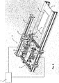
- Fig. 1 shows a schematic representation of a first embodiment of a production system 10 according to the invention for the production of vehicle license plates 41.
- This comprises an automatic embossing press 20 and a hot embossing machine 30, which can be designed in a known manner and whose structure for this invention will not be described in detail.
- the embossing press 20 is designed to process continuously supplied license plate blanks by introducing an embossing therein. This is, for example, a circumferential border and a legend that are raised.
- blanks are continuously fed to the embossing press 20, which can be done, for example, by means of a stack 21 of blanks which are successively embossed by the embossing press 20.
- Each number plate is given an individual legend, which can be transferred to the embossing press by a computer control.
- embossed marks 40 are ejected from the press and placed on a conveyor 11.
- This conveyor 11 is preferably a conveyor belt, for example in the form of a belt conveyor.
- the hot embossing machine 30 is designed to print these embossed identifiers 40 by means of hot embossing, in order to use them to produce vehicle identification plates 41. At elevated temperatures, color is applied to the raised areas of the License plate applied.
- the labels 40 are continuously fed to the hot stamping machine 30 via a conveying means 12 and are also moved by this conveying means 12 through the hot stamping machine 30.
- This funding 12 can also be a belt conveyor.
- the hot stamping machine 30 can be designed in various ways in order to continuously apply color to continuous markings 40.
- a double head hot stamping machine with two pressure rollers 32 and 32 ' is used.
- the hot stamping foil 31 unwinds continuously from a supply spool 33, and used hot stamping foil winds up on a collecting spool 34.
- the film 31 thus runs from the supply spool 33 under the pressure rollers 32, 32 'to the collecting spool 34.
- the pressure rollers 32, 32' are preferably designed to be vertically movable so that they can be raised and lowered. They are raised, for example, when the hot stamping machine 30 is not in operation or is temporarily stopped.
- a conversion device 13 which is connected to a control unit 14, is arranged between the first conveyor 12 and the second conveyor 11 and.
- This control unit 14 is in the Fig. 1 only shown schematically and can be arranged as desired. It can be integrated in the conversion device 13 or arranged at a distance from it. Furthermore, it can be a central control unit that is also connected to other components of the system. In particular, it can be connected for communication with the embossing press 20 and the hot embossing machine 30, as is the case in the exemplary embodiment of FIG Fig. 1 is provided.
- the conversion device 13 is designed to convert labels 40 from the conveyor 11 to the other conveyor 12, the labels being temporary be buffered in a buffer of the conversion device.
- the control unit 14 controls this buffer in particular in such a way that the identifiers are stored on the conveying means 12 one after the other at a predetermined distance X.
- This distance X typically differs from the distance Y of the identifiers 40 on the conveying means 11.
- the distance X is smaller than the distance Y, since the smallest possible distance between the identifiers 40 is aimed for in the hot stamping machine 30.
- the distance Y of the identifiers 40 on the conveying means 11, on the other hand, can be chosen to be larger, for example to facilitate the transfer process from the conveying means 11 into the buffer.
- FIGS Figures 2 and 3 A possible embodiment of such a conversion device 13 with a buffer is shown in FIGS Figures 2 and 3 shown.
- Fig. 2 shows a first three-dimensional view of a transfer device 13, which is arranged between two conveying means 11 and 12. With the conveying means 11, identifiers 40 are transported to the transfer device 13, the identifiers 40 being transported longitudinally, for example.
- the identifiers 40 have a width B.
- the relocating device 13 comprises a gripping device 50 with which identifiers 40 can be lifted from the conveying means 11 and converted into the buffer.
- This gripping device 50 can be formed by one or more suction grippers, for example two suction elements 53 and 54 can be provided on an elongated connecting profile.
- suction elements 53, 54 are connected to hoses, not shown, for generating and releasing a negative pressure in the suction elements 53, 54.
- the suction gripper 50 thus formed can be moved along a rail 51 via a slide 52.
- the direction of movement of the carriage 52 runs in the direction of the first conveying means 11.
- the suction gripper 50 can thus be moved with the carriage 52 into a position above a label 40 and lowered there by means of a lifting device 55.
- the suction elements 53, 54 suck the label 40 and the suction gripper 50 is raised and moved along the conveyor 11 to the buffer.
- the buffer is formed by at least two storage levels, which in the embodiment of the Figures 2 . 3 and 4 are arranged one above the other. Three storage levels were selected. These storage levels are formed by several holding means, with which license plates can be kept on one level. These are, for example, support elements in several levels. The support elements can be formed by small plates, as in the Fig. 2 is shown. Each storage level is formed by four support elements, two of which lie opposite each other so that a mark can be placed on them. In this case, two plates each lie on a first support side 63 of the buffer and two further plates on an opposite support side 64. The distance between the plates is chosen accordingly.
- FIG. 2 three superimposed support elements are identified by way of example with the reference numbers 60, 61 and 62.
- the support elements 60, 61, 62 and 60 ', 61', 62 'on one side could also be continuous, so that they form three longer support webs.
- pin-shaped support elements or elements with other shapes can also be selected.
- the support elements are movable and can be controlled by the control unit 14 on both support sides 63, 64 in such a way that their position and thus the distance between opposite support elements can be changed.
- a first position the distance between opposing support elements is selected such that an identifier 40 can be placed on the support elements.
- the distance is thus smaller than the width B of the identifier 40.
- a second position the distance is greater than the width B, so that an identifier 40 is no longer held on the storage plane, but falls off from it.
- the support elements can be movable in the horizontal direction. However, they can also be designed to be tiltable and can be folded down to increase the distance. A combination of both movements is also possible.
- the conveying means 12 runs underneath the buffer formed in this way. If labels 40 fall out of the buffer, they fall on the conveying means 12, which transports them to the hot stamping machine 30.
- the two funding means can also be realized by a single conveyor belt which runs below the transfer device 13.
- the buffer is arranged in such a way that marks can first be stored with the suction gripper 50 on the top storage level of the buffer.
- the suction gripper 50 then moves back along the rail 51 and picks up the next indicator.
- their support elements have a corresponding distance from one another. Before the next license plate is stored on the top level, this distance is reduced by the control unit 14, so that the license plate falls onto the middle storage level. Then it falls down to the lowest level and the license plate from the highest level falls down to the middle level. This way the buffer is filled and the top level is free again for the next number plate.
- Fig. 4 shows in Figure (a) the state of the filled buffer with three indicators on each level.
- the control unit now controls the buffer in such a way that the lowest indicator can fall onto the first funding (not shown).
- the distance between opposite support elements is increased, as shown in Figure (b) Fig. 4 is shown. In this case, this takes place in such a way that the indicators on the first funding have a predetermined distance X from one another. This distance X is on the order of about 5 mm, for example.
- a damping material can be attached to the top of the support elements in order to dampen the falling of license plates onto levels below.
- This can be, for example, an elastomer material, a polyester-urethane rubber in particular having proven to be expedient.
- the product Vulkollan can be used in cellular form.
- any other type of suitable damping material can also be used.
- the top of this damping material is preferably provided with a stable sliding surface so that the damping material is not damaged and the marks can slide off the support elements.
- the sliding surface can be formed, for example, by a thin sheet metal layer or a plastic layer.
- the figures describe an embodiment of a hot stamping machine 30 in combination with an automatic stamping press.
- the hot stamping machine 30 and the transfer device 13 shown can also be operated with other sources for stamped marks 40.
- embossed marks can also be embossed in batch mode and then placed on the second conveyor belt 11 and thus fed to the buffer with the gripping device 50.
- labels can be placed directly from above on the top level of the buffer. This can be done manually or by mechanical means, a second conveying means 11 being unnecessary in both cases.
- the invention is thus not limited to an embodiment with an automatic embossing press and a second conveying means 11, but rather the conversion device 13 according to the invention in front of the conveying means 11 for feeding labels to a hot stamping machine 30 can advantageously also be used in other production situations.
- Fig. 5 shows an example of a production system 10 'for such an application, in which stencils 70 are successively deposited on embossed marks 40 from the buffer of the transfer device 13, which are moved below the buffer on the conveyor belt 12 to the hot stamping machine 30.
- the hot stamping machine 30 can be like the hot stamping machine of the embodiment of FIG Fig. 1 be trained.
- the stencils 70 can be flat plates which are made, for example, of sheet metal or a plastic such as PTFE.
- the dimensions of the templates essentially correspond to the dimensions of the labels to be printed.
- Recesses are made in these stencils, which leave free those areas in which 30 color is to be applied to an embossed license plate with the hot stamping machine.
- the embossed marks 40 can be transported to the hot stamping machine at regular intervals, or the intervals can vary.
- one of the conversion devices described above can be provided in front of the conversion device 13.
- the production system 10 ' would thus comprise two buffers with different functions.
- embossed labels could be stored on a means of transport at predetermined intervals, and with a second buffer, templates would be placed on these labels.
- the functioning of the two buffers could be identical or different.
- a buffer with several stacking levels arranged one above the other has also proven to be advantageous.
- a sensor means 71 can be provided so that the stencils 70 are deposited at the correct time from the buffer of the transfer device 13 onto the identifier 40 moving beneath them. This sensor means 71 can be used to determine where a label is located on the transport means 12 or when it is located below the transfer device 13 in such a way that a falling template 70 comes to rest correctly on the label.
- the sensor means can be a light barrier, for example.
- the templates 70 can also be fed to the transfer device in different ways. For example, they can be fed manually or by machine. In particular, returning used templates from a point behind the hot stamping machine 30 back into the buffer of the transfer device is advantageous. This return is in Fig. 5 shown with arrows. Movable suction cups or other suitable means can also be used for the return.
Landscapes
- Engineering & Computer Science (AREA)
- Mechanical Engineering (AREA)
- Physics & Mathematics (AREA)
- Thermal Sciences (AREA)
- Making Paper Articles (AREA)
- Labeling Devices (AREA)
- Delivering By Means Of Belts And Rollers (AREA)
- Automobile Manufacture Line, Endless Track Vehicle, Trailer (AREA)
Priority Applications (1)
| Application Number | Priority Date | Filing Date | Title |
|---|---|---|---|
| PL16757592T PL3344405T3 (pl) | 2015-09-01 | 2016-08-16 | Układ produkcji i sposób produkcji tablic rejestracyjnych pojazdów silnikowych |
Applications Claiming Priority (2)
| Application Number | Priority Date | Filing Date | Title |
|---|---|---|---|
| DE102015114573.1A DE102015114573B4 (de) | 2015-09-01 | 2015-09-01 | Produktionsanlage und Verfahren zur Herstellung von KFZ-Kennzeichenschildern |
| PCT/EP2016/069390 WO2017036783A1 (de) | 2015-09-01 | 2016-08-16 | Produktionsanlage und verfahren zur herstellung von kfz-kennzeichenschildern |
Publications (2)
| Publication Number | Publication Date |
|---|---|
| EP3344405A1 EP3344405A1 (de) | 2018-07-11 |
| EP3344405B1 true EP3344405B1 (de) | 2019-12-25 |
Family
ID=56802462
Family Applications (1)
| Application Number | Title | Priority Date | Filing Date |
|---|---|---|---|
| EP16757592.7A Active EP3344405B1 (de) | 2015-09-01 | 2016-08-16 | Produktionsanlage und verfahren zur herstellung von kfz-kennzeichenschildern |
Country Status (10)
| Country | Link |
|---|---|
| US (1) | US20180243781A1 (pl) |
| EP (1) | EP3344405B1 (pl) |
| CN (1) | CN107921514B (pl) |
| BR (1) | BR112018003632A2 (pl) |
| CA (1) | CA2996367A1 (pl) |
| DE (1) | DE102015114573B4 (pl) |
| DK (1) | DK3344405T3 (pl) |
| ES (1) | ES2776434T3 (pl) |
| PL (1) | PL3344405T3 (pl) |
| WO (1) | WO2017036783A1 (pl) |
Families Citing this family (5)
| Publication number | Priority date | Publication date | Assignee | Title |
|---|---|---|---|---|
| ES2786109B2 (es) * | 2019-04-08 | 2021-02-22 | Ind Samart Sa | Procedimiento para la confeccion y pintado de caracteres embutidos en placas de matricula y lamina tubular termotransferible para llevar a cabo dicho metodo |
| CN110000044A (zh) * | 2019-04-11 | 2019-07-12 | 郑楠楠 | 一种防火隔离带的制备装置 |
| CN111114111A (zh) * | 2020-01-22 | 2020-05-08 | 金伟国 | 一种烫印机 |
| CN113536818B (zh) * | 2021-06-30 | 2024-09-13 | 江苏华锐频科技有限公司 | 电子车牌自动生产线系统及其控制方法 |
| CN114833211B8 (zh) * | 2022-05-30 | 2024-08-13 | 重庆公共运输职业学院 | 一种带切割功能的导热片成型装置 |
Family Cites Families (18)
| Publication number | Priority date | Publication date | Assignee | Title |
|---|---|---|---|---|
| US3824921A (en) * | 1972-10-11 | 1974-07-23 | D Alexander | Serial number embossing apparatus |
| FR2539385A1 (fr) * | 1983-01-14 | 1984-07-20 | Commissariat Energie Atomique | Machine pour la fermeture de futs a l'interieur d'une piscine et couvercle de fut prevu pour etre mis en place a l'aide d'une telle machine |
| DE3741232A1 (de) * | 1987-12-05 | 1989-06-15 | Utsch Kg Erich | Vorrichtung zum einfaerben von gepraegten schildern, insbesondere kraftfahrzeug-kennzeichenschildern |
| FR2652766B1 (fr) * | 1989-10-10 | 1995-01-27 | Fabricauto Essarauto | Machine pour l'estampage de caracteres, notamment pour la confection de plaques d'immatriculation. |
| DE19836801A1 (de) * | 1998-08-14 | 2000-02-17 | Utsch Kg Erich | Presse zum Prägen von Schildern, insbesondere Kraftfahrzeug-Kennzeichenschildern |
| WO2000063030A2 (de) * | 1999-04-19 | 2000-10-26 | Erich Utsch Kg | Vorrichtung und verfahren zum bedrucken von verkehrsschildern |
| US6676587B2 (en) * | 2001-09-13 | 2004-01-13 | Hallmark Cards Incorporated | Integrated emboss module |
| DE102004039039B4 (de) * | 2004-08-11 | 2006-12-14 | Hahn, Karlheinz, Dipl.-Ing. | Verfahren und Vorrichtung zum Prägen/Färben von Kfz-Kennzeichen-Schildern |
| DE102004039037B3 (de) * | 2004-08-11 | 2006-01-05 | Hahn, Karlheinz, Dipl.-Ing. | Verfahren und Vorrichtung zum Prägen/Färben von Kfz-Kennzeichenschildern |
| US20100307352A1 (en) * | 2009-06-08 | 2010-12-09 | Kuo-Cheng Huang | Keyboard thermal transfer printer |
| EP2512807B1 (fr) * | 2009-12-18 | 2015-09-23 | Bobst Mex Sa | Dispositif d'impression par estampage a chaud |
| CN201863480U (zh) * | 2010-08-04 | 2011-06-15 | 林树强 | 一种车牌专用烫印机 |
| EP2616243B1 (fr) * | 2010-09-16 | 2016-07-27 | Bobst Mex Sa | Dispositif d'impression par estampage |
| CN102897112A (zh) * | 2011-07-27 | 2013-01-30 | 众睿科技有限公司 | 车牌装置及车牌制造方法 |
| FR3001649B1 (fr) * | 2013-02-04 | 2015-08-07 | Illinois Tool Works | Machine et procede de marquage d'articles |
| DE102013007810A1 (de) * | 2013-05-07 | 2014-11-13 | Friedrich Meyer | Maschine zur Herstellung von Schildern, insbesondere Kraftfahrzeug-Kennzeichenschildern |
| GB2514822B (en) * | 2013-06-06 | 2015-05-13 | Yakov Miller | Foil stamping machine |
| JP6278805B2 (ja) * | 2014-04-08 | 2018-02-14 | ローランドディー.ジー.株式会社 | 打刻装置および打刻方法 |
-
2015
- 2015-09-01 DE DE102015114573.1A patent/DE102015114573B4/de not_active Expired - Fee Related
-
2016
- 2016-08-16 PL PL16757592T patent/PL3344405T3/pl unknown
- 2016-08-16 WO PCT/EP2016/069390 patent/WO2017036783A1/de not_active Ceased
- 2016-08-16 BR BR112018003632-3A patent/BR112018003632A2/pt not_active Application Discontinuation
- 2016-08-16 CA CA2996367A patent/CA2996367A1/en not_active Abandoned
- 2016-08-16 CN CN201680050312.0A patent/CN107921514B/zh not_active Expired - Fee Related
- 2016-08-16 ES ES16757592T patent/ES2776434T3/es active Active
- 2016-08-16 EP EP16757592.7A patent/EP3344405B1/de active Active
- 2016-08-16 US US15/754,527 patent/US20180243781A1/en not_active Abandoned
- 2016-08-16 DK DK16757592.7T patent/DK3344405T3/da active
Non-Patent Citations (1)
| Title |
|---|
| None * |
Also Published As
| Publication number | Publication date |
|---|---|
| PL3344405T3 (pl) | 2020-06-15 |
| CN107921514B (zh) | 2019-09-13 |
| CA2996367A1 (en) | 2017-03-09 |
| BR112018003632A2 (pt) | 2018-09-25 |
| CN107921514A (zh) | 2018-04-17 |
| DE102015114573A1 (de) | 2017-03-02 |
| DK3344405T3 (da) | 2020-03-23 |
| WO2017036783A1 (de) | 2017-03-09 |
| ES2776434T3 (es) | 2020-07-30 |
| EP3344405A1 (de) | 2018-07-11 |
| US20180243781A1 (en) | 2018-08-30 |
| DE102015114573B4 (de) | 2020-10-29 |
Similar Documents
| Publication | Publication Date | Title |
|---|---|---|
| EP3344405B1 (de) | Produktionsanlage und verfahren zur herstellung von kfz-kennzeichenschildern | |
| DE69418438T2 (de) | Vorrichtung und Verfahren zum Palettieren von instabilen Gegenständen | |
| DE102004058598B4 (de) | Vorrichtung zur veredelnden Bearbeitung von bogenförmigen Substraten | |
| DE102007049168B4 (de) | Vorrichtung und Verfahren zum Verschieben von aus erwärmten thermoplastischen Halbzeugen geformten und ausgestanzten Tiefziehprodukten von einer Thermoformmaschine zu einer Verarbeitungsstation | |
| DE3022525C2 (de) | Verfahren und Vorrichtung zum Aufbringen eines Aufklebers auf eine Endlosbahn | |
| EP3017940B2 (de) | Verfahren und eine Vorrichtung zur Herstellung von Säcken aus schlauchförmigen Sackkörpern | |
| EP2110348A1 (de) | Annahmestation und Paketgreifer einer Palettiereinrichtung sowie Verfahren zum Übergeben von Paketen von einer Annahmestation an einen Paketgreifer | |
| EP3585717B1 (de) | Verfahren und vorrichtung zum stapeln von flächigen materialbogen sowie eine druck- und/oder lackiermaschine | |
| EP1520682B1 (de) | Thermoformanlage | |
| DE2058606A1 (de) | Verfahren und Vorrichtung zum seitlichen Ausrichten von Blaettern,insbesondere bei einer Druckpresse | |
| EP2796293B1 (de) | Verfahren und Vorrichtung zum exakten Legen von Beschichtungsmaterial auf einer in einer Presse zu beschichtenden Trägerplatte | |
| DE102016109225A1 (de) | Höhenförderer | |
| DE19926822A1 (de) | Plattenwechselvorrichtung | |
| EP2213475B1 (de) | Prägevorrichtung und Verfahren | |
| EP2029360B2 (de) | Verfahren und Vorrichtung zur Herstellung von Folienverbünden | |
| EP3527500A1 (de) | Verpackungsvorrichtung für artikel und verfahren zum betreiben einer zur handhabung flächiger verpackungszuschnitte ausgebildeten verpackungsvorrichtung | |
| EP1439922B1 (de) | Greifzangenloser tafeltransport mit hoher geschwindigkeit | |
| DE102012007606A1 (de) | Verfahren zur Bogenübergabe und Stanzmaschinemit Greifer-Transportsystem | |
| DE102009038122B4 (de) | Plattenaufteilanlage | |
| DE2232394C3 (de) | Fördertisch zum Überleiten von flachen Werkstücken, die von einer Bearbeitungsmaschine angeliefert werden, auf eine Vorrichtung, welche die Werkstücke in einem anderen Folgerhythmuü weiterbearbeitet | |
| EP3981575B1 (de) | Anordnung zum zuführen eines halbzeugs zu einer thermoformmaschine, anordnung zum thermoformen, sowie verfahren | |
| EP2758225B1 (de) | Etikettiereinrichtung für eine thermoformanlage und verfahren | |
| EP3702157B1 (de) | Verfahren und vorrichtung zum exakten legen von bögen | |
| DE102011116220A1 (de) | Verfahren zum Betreiben einer bogenbearbeitenden Maschine mit speziellem Geschwindigkeitsprofil und solche Maschine | |
| DE2317679A1 (de) | Vorrichtung zur stapelung von fliesen, kacheln und dergleichen auf eine abstellflaeche |
Legal Events
| Date | Code | Title | Description |
|---|---|---|---|
| STAA | Information on the status of an ep patent application or granted ep patent |
Free format text: STATUS: THE INTERNATIONAL PUBLICATION HAS BEEN MADE |
|
| PUAI | Public reference made under article 153(3) epc to a published international application that has entered the european phase |
Free format text: ORIGINAL CODE: 0009012 |
|
| STAA | Information on the status of an ep patent application or granted ep patent |
Free format text: STATUS: REQUEST FOR EXAMINATION WAS MADE |
|
| 17P | Request for examination filed |
Effective date: 20180222 |
|
| AK | Designated contracting states |
Kind code of ref document: A1 Designated state(s): AL AT BE BG CH CY CZ DE DK EE ES FI FR GB GR HR HU IE IS IT LI LT LU LV MC MK MT NL NO PL PT RO RS SE SI SK SM TR |
|
| AX | Request for extension of the european patent |
Extension state: BA ME |
|
| DAV | Request for validation of the european patent (deleted) | ||
| DAX | Request for extension of the european patent (deleted) | ||
| GRAP | Despatch of communication of intention to grant a patent |
Free format text: ORIGINAL CODE: EPIDOSNIGR1 |
|
| STAA | Information on the status of an ep patent application or granted ep patent |
Free format text: STATUS: GRANT OF PATENT IS INTENDED |
|
| INTG | Intention to grant announced |
Effective date: 20190903 |
|
| GRAS | Grant fee paid |
Free format text: ORIGINAL CODE: EPIDOSNIGR3 |
|
| GRAA | (expected) grant |
Free format text: ORIGINAL CODE: 0009210 |
|
| STAA | Information on the status of an ep patent application or granted ep patent |
Free format text: STATUS: THE PATENT HAS BEEN GRANTED |
|
| AK | Designated contracting states |
Kind code of ref document: B1 Designated state(s): AL AT BE BG CH CY CZ DE DK EE ES FI FR GB GR HR HU IE IS IT LI LT LU LV MC MK MT NL NO PL PT RO RS SE SI SK SM TR |
|
| REG | Reference to a national code |
Ref country code: GB Ref legal event code: FG4D Free format text: NOT ENGLISH |
|
| REG | Reference to a national code |
Ref country code: CH Ref legal event code: EP |
|
| REG | Reference to a national code |
Ref country code: AT Ref legal event code: REF Ref document number: 1216601 Country of ref document: AT Kind code of ref document: T Effective date: 20200115 |
|
| REG | Reference to a national code |
Ref country code: DE Ref legal event code: R096 Ref document number: 502016008156 Country of ref document: DE |
|
| REG | Reference to a national code |
Ref country code: IE Ref legal event code: FG4D Free format text: LANGUAGE OF EP DOCUMENT: GERMAN |
|
| REG | Reference to a national code |
Ref country code: SE Ref legal event code: TRGR |
|
| REG | Reference to a national code |
Ref country code: NL Ref legal event code: FP |
|
| REG | Reference to a national code |
Ref country code: NO Ref legal event code: T2 Effective date: 20191225 Ref country code: DK Ref legal event code: T3 Effective date: 20200316 |
|
| PG25 | Lapsed in a contracting state [announced via postgrant information from national office to epo] |
Ref country code: BG Free format text: LAPSE BECAUSE OF FAILURE TO SUBMIT A TRANSLATION OF THE DESCRIPTION OR TO PAY THE FEE WITHIN THE PRESCRIBED TIME-LIMIT Effective date: 20200325 Ref country code: FI Free format text: LAPSE BECAUSE OF FAILURE TO SUBMIT A TRANSLATION OF THE DESCRIPTION OR TO PAY THE FEE WITHIN THE PRESCRIBED TIME-LIMIT Effective date: 20191225 Ref country code: LV Free format text: LAPSE BECAUSE OF FAILURE TO SUBMIT A TRANSLATION OF THE DESCRIPTION OR TO PAY THE FEE WITHIN THE PRESCRIBED TIME-LIMIT Effective date: 20191225 Ref country code: GR Free format text: LAPSE BECAUSE OF FAILURE TO SUBMIT A TRANSLATION OF THE DESCRIPTION OR TO PAY THE FEE WITHIN THE PRESCRIBED TIME-LIMIT Effective date: 20200326 Ref country code: LT Free format text: LAPSE BECAUSE OF FAILURE TO SUBMIT A TRANSLATION OF THE DESCRIPTION OR TO PAY THE FEE WITHIN THE PRESCRIBED TIME-LIMIT Effective date: 20191225 |
|
| REG | Reference to a national code |
Ref country code: LT Ref legal event code: MG4D |
|
| PG25 | Lapsed in a contracting state [announced via postgrant information from national office to epo] |
Ref country code: HR Free format text: LAPSE BECAUSE OF FAILURE TO SUBMIT A TRANSLATION OF THE DESCRIPTION OR TO PAY THE FEE WITHIN THE PRESCRIBED TIME-LIMIT Effective date: 20191225 Ref country code: RS Free format text: LAPSE BECAUSE OF FAILURE TO SUBMIT A TRANSLATION OF THE DESCRIPTION OR TO PAY THE FEE WITHIN THE PRESCRIBED TIME-LIMIT Effective date: 20191225 |
|
| PG25 | Lapsed in a contracting state [announced via postgrant information from national office to epo] |
Ref country code: AL Free format text: LAPSE BECAUSE OF FAILURE TO SUBMIT A TRANSLATION OF THE DESCRIPTION OR TO PAY THE FEE WITHIN THE PRESCRIBED TIME-LIMIT Effective date: 20191225 |
|
| REG | Reference to a national code |
Ref country code: ES Ref legal event code: FG2A Ref document number: 2776434 Country of ref document: ES Kind code of ref document: T3 Effective date: 20200730 |
|
| PG25 | Lapsed in a contracting state [announced via postgrant information from national office to epo] |
Ref country code: EE Free format text: LAPSE BECAUSE OF FAILURE TO SUBMIT A TRANSLATION OF THE DESCRIPTION OR TO PAY THE FEE WITHIN THE PRESCRIBED TIME-LIMIT Effective date: 20191225 Ref country code: PT Free format text: LAPSE BECAUSE OF FAILURE TO SUBMIT A TRANSLATION OF THE DESCRIPTION OR TO PAY THE FEE WITHIN THE PRESCRIBED TIME-LIMIT Effective date: 20200520 Ref country code: RO Free format text: LAPSE BECAUSE OF FAILURE TO SUBMIT A TRANSLATION OF THE DESCRIPTION OR TO PAY THE FEE WITHIN THE PRESCRIBED TIME-LIMIT Effective date: 20191225 Ref country code: CZ Free format text: LAPSE BECAUSE OF FAILURE TO SUBMIT A TRANSLATION OF THE DESCRIPTION OR TO PAY THE FEE WITHIN THE PRESCRIBED TIME-LIMIT Effective date: 20191225 |
|
| PG25 | Lapsed in a contracting state [announced via postgrant information from national office to epo] |
Ref country code: SM Free format text: LAPSE BECAUSE OF FAILURE TO SUBMIT A TRANSLATION OF THE DESCRIPTION OR TO PAY THE FEE WITHIN THE PRESCRIBED TIME-LIMIT Effective date: 20191225 Ref country code: SK Free format text: LAPSE BECAUSE OF FAILURE TO SUBMIT A TRANSLATION OF THE DESCRIPTION OR TO PAY THE FEE WITHIN THE PRESCRIBED TIME-LIMIT Effective date: 20191225 Ref country code: IS Free format text: LAPSE BECAUSE OF FAILURE TO SUBMIT A TRANSLATION OF THE DESCRIPTION OR TO PAY THE FEE WITHIN THE PRESCRIBED TIME-LIMIT Effective date: 20200425 |
|
| REG | Reference to a national code |
Ref country code: DE Ref legal event code: R097 Ref document number: 502016008156 Country of ref document: DE |
|
| PLBE | No opposition filed within time limit |
Free format text: ORIGINAL CODE: 0009261 |
|
| STAA | Information on the status of an ep patent application or granted ep patent |
Free format text: STATUS: NO OPPOSITION FILED WITHIN TIME LIMIT |
|
| PG25 | Lapsed in a contracting state [announced via postgrant information from national office to epo] |
Ref country code: SI Free format text: LAPSE BECAUSE OF FAILURE TO SUBMIT A TRANSLATION OF THE DESCRIPTION OR TO PAY THE FEE WITHIN THE PRESCRIBED TIME-LIMIT Effective date: 20191225 |
|
| 26N | No opposition filed |
Effective date: 20200928 |
|
| PG25 | Lapsed in a contracting state [announced via postgrant information from national office to epo] |
Ref country code: IT Free format text: LAPSE BECAUSE OF FAILURE TO SUBMIT A TRANSLATION OF THE DESCRIPTION OR TO PAY THE FEE WITHIN THE PRESCRIBED TIME-LIMIT Effective date: 20191225 |
|
| REG | Reference to a national code |
Ref country code: DE Ref legal event code: R119 Ref document number: 502016008156 Country of ref document: DE |
|
| REG | Reference to a national code |
Ref country code: NO Ref legal event code: MMEP |
|
| REG | Reference to a national code |
Ref country code: DK Ref legal event code: EBP Effective date: 20200831 |
|
| REG | Reference to a national code |
Ref country code: SE Ref legal event code: EUG |
|
| PG25 | Lapsed in a contracting state [announced via postgrant information from national office to epo] |
Ref country code: MC Free format text: LAPSE BECAUSE OF FAILURE TO SUBMIT A TRANSLATION OF THE DESCRIPTION OR TO PAY THE FEE WITHIN THE PRESCRIBED TIME-LIMIT Effective date: 20191225 |
|
| REG | Reference to a national code |
Ref country code: CH Ref legal event code: PL |
|
| REG | Reference to a national code |
Ref country code: NL Ref legal event code: MM Effective date: 20200901 |
|
| GBPC | Gb: european patent ceased through non-payment of renewal fee |
Effective date: 20200816 |
|
| PG25 | Lapsed in a contracting state [announced via postgrant information from national office to epo] |
Ref country code: NO Free format text: LAPSE BECAUSE OF NON-PAYMENT OF DUE FEES Effective date: 20200831 Ref country code: LU Free format text: LAPSE BECAUSE OF NON-PAYMENT OF DUE FEES Effective date: 20200816 Ref country code: LI Free format text: LAPSE BECAUSE OF NON-PAYMENT OF DUE FEES Effective date: 20200831 Ref country code: CH Free format text: LAPSE BECAUSE OF NON-PAYMENT OF DUE FEES Effective date: 20200831 |
|
| REG | Reference to a national code |
Ref country code: BE Ref legal event code: MM Effective date: 20200831 |
|
| PG25 | Lapsed in a contracting state [announced via postgrant information from national office to epo] |
Ref country code: SE Free format text: LAPSE BECAUSE OF NON-PAYMENT OF DUE FEES Effective date: 20200817 |
|
| PG25 | Lapsed in a contracting state [announced via postgrant information from national office to epo] |
Ref country code: DE Free format text: LAPSE BECAUSE OF NON-PAYMENT OF DUE FEES Effective date: 20210302 Ref country code: FR Free format text: LAPSE BECAUSE OF NON-PAYMENT OF DUE FEES Effective date: 20200831 |
|
| PG25 | Lapsed in a contracting state [announced via postgrant information from national office to epo] |
Ref country code: GB Free format text: LAPSE BECAUSE OF NON-PAYMENT OF DUE FEES Effective date: 20200816 Ref country code: IE Free format text: LAPSE BECAUSE OF NON-PAYMENT OF DUE FEES Effective date: 20200816 Ref country code: BE Free format text: LAPSE BECAUSE OF NON-PAYMENT OF DUE FEES Effective date: 20200831 Ref country code: DK Free format text: LAPSE BECAUSE OF NON-PAYMENT OF DUE FEES Effective date: 20200831 |
|
| PG25 | Lapsed in a contracting state [announced via postgrant information from national office to epo] |
Ref country code: NL Free format text: LAPSE BECAUSE OF NON-PAYMENT OF DUE FEES Effective date: 20200901 |
|
| REG | Reference to a national code |
Ref country code: ES Ref legal event code: FD2A Effective date: 20211228 |
|
| PG25 | Lapsed in a contracting state [announced via postgrant information from national office to epo] |
Ref country code: ES Free format text: LAPSE BECAUSE OF NON-PAYMENT OF DUE FEES Effective date: 20200817 |
|
| PG25 | Lapsed in a contracting state [announced via postgrant information from national office to epo] |
Ref country code: TR Free format text: LAPSE BECAUSE OF FAILURE TO SUBMIT A TRANSLATION OF THE DESCRIPTION OR TO PAY THE FEE WITHIN THE PRESCRIBED TIME-LIMIT Effective date: 20191225 Ref country code: MT Free format text: LAPSE BECAUSE OF FAILURE TO SUBMIT A TRANSLATION OF THE DESCRIPTION OR TO PAY THE FEE WITHIN THE PRESCRIBED TIME-LIMIT Effective date: 20191225 Ref country code: CY Free format text: LAPSE BECAUSE OF FAILURE TO SUBMIT A TRANSLATION OF THE DESCRIPTION OR TO PAY THE FEE WITHIN THE PRESCRIBED TIME-LIMIT Effective date: 20191225 |
|
| PG25 | Lapsed in a contracting state [announced via postgrant information from national office to epo] |
Ref country code: MK Free format text: LAPSE BECAUSE OF FAILURE TO SUBMIT A TRANSLATION OF THE DESCRIPTION OR TO PAY THE FEE WITHIN THE PRESCRIBED TIME-LIMIT Effective date: 20191225 |
|
| REG | Reference to a national code |
Ref country code: AT Ref legal event code: MM01 Ref document number: 1216601 Country of ref document: AT Kind code of ref document: T Effective date: 20210816 |
|
| PG25 | Lapsed in a contracting state [announced via postgrant information from national office to epo] |
Ref country code: AT Free format text: LAPSE BECAUSE OF NON-PAYMENT OF DUE FEES Effective date: 20210816 |
|
| PG25 | Lapsed in a contracting state [announced via postgrant information from national office to epo] |
Ref country code: PL Free format text: LAPSE BECAUSE OF NON-PAYMENT OF DUE FEES Effective date: 20200816 |