EP1520682B1 - Thermoformanlage - Google Patents
Thermoformanlage Download PDFInfo
- Publication number
- EP1520682B1 EP1520682B1 EP04016147A EP04016147A EP1520682B1 EP 1520682 B1 EP1520682 B1 EP 1520682B1 EP 04016147 A EP04016147 A EP 04016147A EP 04016147 A EP04016147 A EP 04016147A EP 1520682 B1 EP1520682 B1 EP 1520682B1
- Authority
- EP
- European Patent Office
- Prior art keywords
- tool
- station
- conveyor
- chain
- unit
- Prior art date
- Legal status (The legal status is an assumption and is not a legal conclusion. Google has not performed a legal analysis and makes no representation as to the accuracy of the status listed.)
- Expired - Lifetime
Links
Images


Classifications
-
- B—PERFORMING OPERATIONS; TRANSPORTING
- B29—WORKING OF PLASTICS; WORKING OF SUBSTANCES IN A PLASTIC STATE IN GENERAL
- B29C—SHAPING OR JOINING OF PLASTICS; SHAPING OF MATERIAL IN A PLASTIC STATE, NOT OTHERWISE PROVIDED FOR; AFTER-TREATMENT OF THE SHAPED PRODUCTS, e.g. REPAIRING
- B29C51/00—Shaping by thermoforming, i.e. shaping sheets or sheet like preforms after heating, e.g. shaping sheets in matched moulds or by deep-drawing; Apparatus therefor
- B29C51/26—Component parts, details or accessories; Auxiliary operations
- B29C51/261—Handling means, e.g. transfer means, feeding means
-
- B—PERFORMING OPERATIONS; TRANSPORTING
- B29—WORKING OF PLASTICS; WORKING OF SUBSTANCES IN A PLASTIC STATE IN GENERAL
- B29C—SHAPING OR JOINING OF PLASTICS; SHAPING OF MATERIAL IN A PLASTIC STATE, NOT OTHERWISE PROVIDED FOR; AFTER-TREATMENT OF THE SHAPED PRODUCTS, e.g. REPAIRING
- B29C31/00—Handling, e.g. feeding of the material to be shaped, storage of plastics material before moulding; Automation, i.e. automated handling lines in plastics processing plants, e.g. using manipulators or robots
- B29C31/006—Handling moulds, e.g. between a mould store and a moulding machine
Definitions
- the invention relates to a thermoforming plant with at least one station for the production or processing of moldings that can be produced from a film, in which the film is detected at both longitudinal edges by a respective conveyor and can be conveyed through the at least one station.
- Thermoforming plants of this type are generally known, see document DE 100 22 269 A1.
- the first type of replacement has the disadvantage that the parts belonging together, for example, upper and lower tool must be aligned with each other again, which is time consuming.
- the second type of exchange in the form of a block does not have this disadvantage, but requires molding stations or punching stations or stacking stations, which must have a large stroke, so that the entire block, consisting of upper and lower on the upper or lower table or on an upper or lower support means arranged tools or other devices below or above the respective conveyor laterally can be taken out. Large strokes require correspondingly large systems that are correspondingly expensive.
- the object of the invention is to provide a thermoforming system, in which a tool change or a change of other processing devices, regardless of the available stroke of the tools receiving tables or the corresponding holders for the devices, is feasible.
- thermoforming system specified in the preamble of claim 1 according to the invention that at least one of the conveyors can be transversely to the conveying direction from its working position into a second position, in the one or one for the production or processing of the moldings serving tool or serving device is independent of the existing displacement or stroke of the tool or the device bearing table or other carrying device interchangeable.
- the transport device can be moved out of the area required for the change of the tool or the processing device, it is possible to make a tool change even in such systems that have no large table lift or other displacement for the corresponding holding devices to the Tool or the processing device can move out laterally from the working position below or above the transport device.
- the individual tool parts that is, upper tool and lower tool or other two-part devices can remain in this way in their mutually aligned or centered position whereby the subsequent centering in the reuse of these tools and devices deleted.
- the main advantage is that the individual stations, whether forming station, punching station, etc., in the extensibility of holding the individual tool parts or device parts tables or support need not be designed particularly generous, resulting in stations with a lower technical and thus financial Effort leads.
- a further advantageous embodiment of the invention is that the one conveyor parallel to the second conveyor is displaceable. This leads to a structurally simple solution, in particular if, in a further embodiment of the invention for the displacement of the conveyor a width setting for the parallel conveyor is provided. Such a width adjustment device is necessary in order to be able to set the individual conveyors to the respective width of the film to be transported and processed.
- the thermoforming plant schematically illustrated in FIG. 1 comprises a forming station 1, a stamping station 2, chain rails 3, 4 running parallel to each other as conveying device and a stacking station 5.
- the chain rails 3, 4 transport a film 7 rolled up on a roll 6 through the individual stations, namely the forming station 1, the punching station 2 and the stacking station 5.
- After the punching station 2 only a foil grid is present after the shaped parts have been punched out in the punching station 2.
- the punched parts are then stacked in the stacking station from below and transported away after reaching a certain stack height.
- Indicated at 8 is a heating station located in front of the forming station to heat the film.
- Figures 2 to 4 show a cross section through the forming station 1 in different working positions.
- a lower lift table is designated by 9 and an upper table by 10.
- Each of these tables carries a tool and Although the lower table 9 carries a tool 11 and the upper table a tool 12.
- the two tables 9 and 10 are moved apart and the two chain rails 3 and 4 hold a heated foil 7 ready for a molding process, in which the two tools 11 and 12 are brought together to effect the desired deformation of the film into a molded part.
- FIG. 4 shows the forming station in a position in which the block consisting of lower tool 11 and upper tool 12 has already been released from the two tables 9 and 10 and has been extended to a tool change arm 13. From there, the block consisting of the two tools, corresponding to the direction of the arrow 14, arrives at a tool change carriage 15, which serves to remove the tools 11 and 12. After the removal of the tools 11 and 12 other tools can be attached to the tables 9 and 10 in order to produce other moldings can.
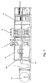
- FIG. 5 shows a plan view of the arrangement according to FIG. 4. The position of the block consisting of the tools 11 and 12 on the tool change arm 13 can be seen from this.
- FIG. 5 also shows a width adjusting device 16, which primarily serves for adjusting the mutual spacing of the chain rails 3 and 4 serving as a transport device for the film, this width adjusting device simultaneously also for displacing the chain rail 4, into those shown in FIGS Used to position 5 shown becomes.
- a width adjusting device 16th To drive the conveyors 3, 4 or the conveyor chains in the longitudinal direction is a schematically indicated in Figure 1 drive device 17th
- FIG. 6 shows a top view of a forming station according to the representation in FIG. 5, however, for a changed tool change.
- the tool block consisting of the upper tool and the lower tool labeled A is pulled or pushed into the position designated A 'on an automatically operating tool change device 18 and is moved from there to position A "
- the tool block is then moved to position B 'so that it can be pulled or pushed from there into the forming station. In this position, the tool block is designated B ".
- the necessary for the change of tools change of energy connections is not shown.
- the tools are held in the individual positions at their operating temperature by preheating, so that, for example, the tool block B is retracted already preheated in the forming station.
- With 19 positioning aids are designated to hold the tool changing device 18 in the correct position with respect to the forming station 1.
- the tool changer 18 may be formed as a shift station, as a carousel or as a paternoster.
Landscapes
- Engineering & Computer Science (AREA)
- Mechanical Engineering (AREA)
- Blow-Moulding Or Thermoforming Of Plastics Or The Like (AREA)
- Confectionery (AREA)
- Air-Conditioning For Vehicles (AREA)
Description
- Die Erfindung bezieht sich auf eine Thermoformanlage mit mindestens einer Station zur Herstellung oder Bearbeitung von aus einer Folie herstellbaren Formteilen, bei der die Folie an beiden Längsrändern durch jeweils eine Fördereinrichtung erfasst ist und durch die mindestens eine Station förderbar ist.
- Thermoformanlagen dieser Art sind allgemein bekannt, siehe Dokument DE 100 22 269 A1.
- Bei einem Werkzeugwechsel in einer Vorformstation, einer Formstation, einer Beschneidestation oder Ausstanzstation sowie einer Stapelstation, gibt es die Möglichkeit, die oberen und unteren Teile eines Werkzeuges oder einer sonstigen Bearbeitungsvorrichtung getrennt voneinander aus der jeweiligen Station herauszuholen und gegen ein entsprechendes anderes Teil zu ersetzen oder die zusammengehörenden Teile des Werkzeuges oder der Bearbeitungsvorrichtung werden in zentrierter Form als Block ausgetauscht.
- Die erste Art des Austausches hat den Nachteil, dass die zusammengehörenden Teile beispielsweise Ober- und Unterwerkzeug wieder zueinander ausgerichtet werden müssen, was zeitaufwendig ist. Die zweite Art des Austausches in Form eines Blockes weist zwar diesen Nachteil nicht auf, erfordert aber Formstationen oder Ausstanzstationen bzw. Stapelstationen, die einen großen Hub aufweisen müssen, damit der gesamte Block, bestehend aus oberen und unteren am Ober- oder Untertisch bzw. an einer oberen oder unteren Trageinrichtung angeordneten Werkzeugen oder sonstigen Vorrichtungen unterhalb oder oberhalb der jeweiligen Fördereinrichtung seitlich herausgenommen werden kann. Große Hubwege erfordern entsprechend große Anlagen, die entsprechend aufwendig sind.
- Aufgabe der Erfindung ist es, eine Thermoformanlage zu schaffen, bei welcher ein Werkzeugwechsel oder ein Wechsel sonstiger Bearbeitungsvorrichtungen, unabhängig vom zur Verfügung stehenden Hub der die Werkzeuge aufnehmenden Tische bzw. der entsprechenden Halterungen für die Vorrichtungen, durchführbar ist.
- Diese Aufgabe wird ausgehend von einer Thermoformanlage der im Oberbegriff des Anspruchs 1 angegebenen Art erfindungsgemäß dadurch gelöst, dass mindestens eine der Fördereinrichtungen quer zur Förderrichtung aus ihrer Arbeitslage in eine zweite Lage überführbar ist, in der ein bzw. eine für die Herstellung oder Bearbeitung der Formteile dienendes Werkzeug oder dienende Vorrichtung unabhängig vom vorhandenen Verschiebeweg oder Hub des das Werkzeug oder die Vorrichtung tragenden Tisches oder sonstigen Tragevorrichtung auswechselbar ist.
- Dadurch, dass die Transportvorrichtung aus demjenigen Bereich herausfahrbar ist, der für den Wechsel des Werkzeuges oder der Bearbeitungsvorrichtung benötigt wird, ist es möglich, einen Werkzeugwechsel auch bei solchen Anlagen vorzunehmen, die keinen großen Tischhub oder sonstigen Verschiebeweg für die entsprechenden Haltevorrichtungen aufweisen, um das Werkzeug oder die Bearbeitungsvorrichtung unterhalb oder oberhalb der Transporteinrichtung seitlich aus der Arbeitsposition herausfahren können. Die einzelnen Werkzeugteile, das heißt Oberwerkzeug und Unterwerkzeug oder sonstige zweiteiligen Vorrichtungen, können auf diese Weise in ihrer gegeneinander ausgerichteten bzw. zentrierten Lage verbleiben wodurch das nachträgliche zentrieren bei der Wiederverwendung dieser Werkzeuge und Vorrichtungen entfällt.
- Der Hauptvorteil liegt jedoch darin, dass die einzelnen Stationen, sei es Formstation, Stanzstation usw., in der Ausfahrbarkeit der die einzelnen Werkzeugteile bzw. Vorrichtungsteile haltenden Tische oder Träger nicht besonders großzügig ausgelegt werden müssen, was zu Stationen mit einem geringeren technischen und damit finanziellen Aufwand führt.
- Die in ihrer gegenseitigen Zentrierlage verbleibenden Werkzeugteile oder Vorrichtungsteile können nach dem Wechsel für eine Wiederverwendung an eine Temperierstation angeschlossen bleiben, so dass der spätere Einsatz bei einem wiederholten Wechsel ohne Zeitverzögerung im Arbeitstakt erfolgen kann, da auf ein Wiederaufwärmen bzw. Aufheizen der Werkzeugformen nicht mehr gewartet werden muss.
- In vorteilhafter Ausgestaltung der Erfindung können als Fördereinrichtung eine Nadelkette, Rollenkette oder Riementrieb oder Kluppenkette dienen.
- Eine weitere vorteilhafte Ausgestaltung der Erfindung besteht darin, dass die eine Fördereinrichtung parallel neben die zweite Fördereinrichtung verschiebbar ist. Dies führt zu einer konstruktiv einfachen Lösung, insbesondere dann, wenn in weiterer Ausgestaltung der Erfindung für die Verschiebung der Fördereinrichtung eine Breiteneinstelleinrichtung für die parallel laufenden Fördereinrichtungen vorgesehen ist. Eine solche Breiteneinstelleinrichtung ist notwendig, um die einzelnen Fördereinrichtungen auf die jeweilige Breite der zu transportierenden und zu verarbeitenden Folie einstellen zu können.
- Die Erfindung wird nachfolgend anhand der in der Zeichnung dargestellten Ausführungsbeispiele näher erläutert. In der Zeichnung zeigen:
- Figur 1:
- eine schematische Darstellung einer Thermoformanlage;
- Figur 2:
- eine schematische Darstellung einer Formstation einer Thermoformanlage in Arbeitsposition;
- Figur 3:
- eine Formstation in einer Werkzeugwechselposition;
- Figur 4:
- die Formstation nach den Figuren 2 und 3 mit ausgeschobenem Werkzeug;
- Figur 5:
- eine Draufsicht auf die Formstation gemäß Figur 4;
- Figur 6:
- eine Draufsicht auf eine Formstation eines zweiten Ausführungsbeispieles.
- Die in Figur 1 schematisch dargestellte Thermoformanlage umfasst eine Formstation 1, eine Stanzstation 2, parallel zueinander laufende als Fördereinrichtung dienende Kettenschienen 3, 4 sowie eine Stapelstation 5. Die Kettenschienen 3, 4 transportieren eine auf einer Rolle 6 aufgerollte Folie 7 durch die einzelnen Stationen, nämlich die Formstation 1, die Stanzstation 2 und die Stapelstation 5. Nach der Stanzstation 2 liegt nur noch ein Foliengitter vor, nachdem die geformten Teile in der Stanzstation 2 ausgestanzt wurden. Die ausgestanzten Teile werden dann in der Stapelstation von unten her ineinander gestapelt und nach Erreichen einer bestimmten Stapelhöhe wegbefördert. Mit 8 ist eine Heizstation bezeichnet, die sich vor der Formstation befindet, um die Folie aufzuheizen.
- Die Figuren 2 bis 4 zeigen einen Querschnitt durch die Formstation 1 in verschiedenen Arbeitsstellungen. In dieser Formstation ist ein unterer Hubtisch mit 9 und ein oberer Tisch mit 10 bezeichnet. Jeder dieser Tische trägt ein Werkzeug und zwar trägt der untere Tisch 9 ein Werkzeug 11 und der obere Tisch ein Werkzeug 12. In Figur 2 sind die beiden Tische 9 und 10 auseinandergefahren und die beiden Kettenschienen 3 und 4 halten eine aufgeheizte Folie 7 für einen Formvorgang bereit, bei welchem die beiden Werkzeuge 11 und 12 zusammengefahren werden, um die gewünschte Verformung der Folie zu einem Formteil zu bewirken.
- In Figur 3 sind die beiden Tische 9 und 10 und damit auch die Werkzeuge 11 und 12 in einer gegeneinander zentrierten Stellung zusammengefahren, wobei vorher die eine Kettenschiene 4 neben die Kettenschiene 3 verschoben wurde, um den Platz zwischen den beiden Tischen 9 und 10 an der in Figur 3 rechten Seite freizumachen.
- Figur 4 zeigt die Formstation in einer Stellung, in welcher der aus Unterwerkzeug 11 und Oberwerkzeug 12 bestehende Block bereits von den beiden Tischen 9 und 10 gelöst und auf einen Werkzeugwechselarm 13 ausgefahren ist. Von dort gelangt der aus den beiden Werkzeugen bestehende Block entsprechend der Pfeilrichtung 14 auf einen Werkzeugwechselwagen 15, der zum Abtransport der Werkzeuge 11 und 12 dient. Nach dem Abtransport der Werkzeuge 11 und 12 können an den Tischen 9 und 10 andere Werkzeuge befestigt werden, um andere Formteile herstellen zu können.
- Figur 5 zeigt eine Draufsicht auf die Anordnung gemäß 4. Hieraus ist die Lage des aus den Werkzeugen 11 und 12 bestehenden Blockes auf dem Werkzeugwechselarm 13 erkennbar. Aus Figur 5 ist auch noch eine Breiteneinstelleinrichtung 16 erkennbar, die in erster Linie zur Einstellung des gegenseitigen Abstandes der als Transporteinrichtung für die Folie dienenden Kettenschienen 3 und 4 dient, wobei diese Breiteneinstelleinrichtung gleichzeitig auch zur Verschiebung der Kettenschiene 4, in die in den Figuren 3 bis 5 darstellte Lage eingesetzt wird. Zum Antrieb der Fördereinrichtungen 3, 4 bzw. der Förderketten in Längsrichtung dient eine in Figur 1 schematisch angedeutete Antriebsvorrichtung 17.
- Figur 6 zeigt eine Draufsicht auf eine Formstation entsprechend der Darstellung in Figur 5 jedoch für einen geänderten Werkzeugwechsel.
- Wie aus dieser Figur ersichtlich, wird der mit A bezeichnete aus dem Oberwerkzeug und dem Unterwerkzeug bestehende Werkzeugblock in die mit A' bezeichnete Stellung auf eine automatisch arbeitende Werkzeugwechseleinrichtung 18 gezogen oder geschoben und von dort in die Stellung A" verbracht. Ein zweiter mit B bezeichneter Werkzeugblock wird dann in die Stellung B' verbracht, um von dort in die Formstation hinein gezogen oder geschoben werden zu können. In dieser Stellung ist der Werkzeugblock mit B" bezeichnet. Der für den Wechsel der Werkzeuge notwendige Wechsel der Energieanschlüsse ist nicht dargestellt. Die Werkzeuge werden in den einzelnen Positionen auf ihrer Betriebstemperatur durch Vorwärmen gehalten, so dass beispielsweise der Werkzeugblock B in die Formstation bereits vorgeheizt eingefahren wird. Mit 19 sind Positionierhilfen bezeichnet, um die Werkzeugwechseleinrichtung 18 in der richtigen Position in Bezug auf die Formstation 1 zu halten. Die Werkzeugwechseleinrichtung 18 kann als Verschiebebahnhof, als Karussell oder als Paternoster ausgebildet sein.
Claims (4)
- Thermoformanlage mit mindestens einer Station (1, 2, 5) zur Herstellung oder Bearbeitung von aus einer Folie (7) herstellbaren Formteilen, bei der die Folie (7) an beiden Längsrändern durch jeweils eine Fördereinrichtung (3, 4) erfasst ist und in einer Förderrichtung durch die mindestens eine Station förderbar ist, dadurch gekennzeichnet, dass mindestens eine der Fördereinrichtungen (4) quer zur Förderrichtung aus ihrer Arbeitslage in eine zweite Lage überführbar ist, in der ein bzw. eine für die Herstellung oder Bearbeitung der Formteile dienendes Werkzeug (11, 12) oder dienende Vorrichtung unabhängig vom vorhandenen Verschiebeweg oder Hub des das Werkzeug (11, 12) oder die Vorrichtung tragenden Tisches (9,10) oder einer sonstigen Tragevorrichtung auswechselbar ist.
- Thermoformanlage nach Anspruch 1, dadurch gekennzeichnet, dass als Fördereinrichtung (3, 4) eine Nadelkette, eine Rollenkette, ein Riementrieb oder eine Kluppenkette dient.
- Thermoformanlage nach Anspruch 1 oder 2, dadurch gekennzeichnet, dass die eine Fördereinrichtung (4) parallel neben die zweite Fördereinrichtung (3) verschiebbar ist.
- Thermoformanlage nach einem der Ansprüche 1 bis 3, dadurch gekennzeichnet, dass für die Verschiebung der Fördereinrichtung (4) eine Breiteneinstelleinrichtung (16) für die parallel laufenden Fördereinrichtungen (3, 4) vorgesehen ist.
Applications Claiming Priority (2)
| Application Number | Priority Date | Filing Date | Title |
|---|---|---|---|
| DE10345534 | 2003-09-30 | ||
| DE10345534A DE10345534A1 (de) | 2003-09-30 | 2003-09-30 | Thermoformanlage |
Publications (2)
| Publication Number | Publication Date |
|---|---|
| EP1520682A1 EP1520682A1 (de) | 2005-04-06 |
| EP1520682B1 true EP1520682B1 (de) | 2007-03-21 |
Family
ID=34306173
Family Applications (1)
| Application Number | Title | Priority Date | Filing Date |
|---|---|---|---|
| EP04016147A Expired - Lifetime EP1520682B1 (de) | 2003-09-30 | 2004-07-08 | Thermoformanlage |
Country Status (5)
| Country | Link |
|---|---|
| US (1) | US7361008B2 (de) |
| EP (1) | EP1520682B1 (de) |
| AT (1) | ATE357329T1 (de) |
| DE (2) | DE10345534A1 (de) |
| ES (1) | ES2286537T3 (de) |
Cited By (1)
| Publication number | Priority date | Publication date | Assignee | Title |
|---|---|---|---|---|
| DE102014006968A1 (de) | 2013-05-14 | 2014-12-18 | Kiefel Gmbh | Werkzeugstation einer Thermoformanlage, Thermoformanlage und Verfahren zum Wechseln eines zweiteiligen Werkzeugs an einer Thermoformanlage |
Families Citing this family (17)
| Publication number | Priority date | Publication date | Assignee | Title |
|---|---|---|---|---|
| AU2004100000A4 (en) | 2004-01-02 | 2004-02-12 | Sands Innovations Pty Ltd | Dispensing stirring implement |
| ITMO20040158A1 (it) * | 2004-06-24 | 2004-09-24 | Green Pack S R L | Apparati metodi per confezionare prodotti. |
| BRPI0806943A2 (pt) | 2007-01-31 | 2014-05-06 | Sands Innovations Pty Ltd | Utensílio de dispensação e método de fabricação para o mesmo |
| EP2373551B1 (de) | 2008-12-09 | 2015-04-08 | Sands Innovations Pty Ltd. | Abgabebehälter |
| USD636890S1 (en) | 2009-09-17 | 2011-04-26 | Sands Innovations Pty. Ltd. | Dispensing utensil |
| US8511500B2 (en) | 2010-06-07 | 2013-08-20 | Sands Innovations Pty. Ltd. | Dispensing container |
| US8485360B2 (en) | 2011-03-04 | 2013-07-16 | Sands Innovations Pty, Ltd. | Fracturable container |
| ES2429891T3 (es) * | 2011-05-10 | 2013-11-18 | Multivac Sepp Haggenmüller Gmbh & Co. Kg | Dispositivo de cambio de herramienta |
| US20130266904A1 (en) * | 2012-04-04 | 2013-10-10 | James Martin | Lip Rolling Machine With Rotated Oven Guide Bar |
| ES2646768T3 (es) | 2013-02-22 | 2017-12-15 | Multivac Sepp Haggenmüller Se & Co. Kg | Máquina de envasado por embutición profunda con estación de sellado y procedimiento |
| EP2813345B1 (de) * | 2013-06-12 | 2015-04-08 | Magna Steyr Fuel Systems GesmbH | Verfahren zum Werkzeugwechsel |
| ITMO20130293A1 (it) * | 2013-10-16 | 2015-04-17 | Cms Spa | Apparato di formatura |
| ITMI20132079A1 (it) * | 2013-12-13 | 2015-06-14 | Antonio Rossini | Dispositivo per il confezionamento. |
| ES2613779T3 (es) * | 2013-12-18 | 2017-05-25 | Ulma Packaging Technological Center, S. Coop | Método de cambio de formato para una máquina termoformadora, y máquina termoformadora |
| DE102014219285A1 (de) * | 2014-09-24 | 2016-03-24 | Frimo Group Gmbh | Vorrichtung und Verfahren zur Verarbeitung eines lagenartigen Materials |
| US10576680B2 (en) * | 2015-11-19 | 2020-03-03 | The Boeing Company | Modular thermoforming system |
| DE102020124641A1 (de) | 2020-09-22 | 2022-03-24 | Illig Maschinenbau Gmbh & Co. Kg | Arbeitsstation einer Thermoformmaschine |
Family Cites Families (7)
| Publication number | Priority date | Publication date | Assignee | Title |
|---|---|---|---|---|
| US4428723A (en) * | 1982-02-18 | 1984-01-31 | Thiel Alfons W | Apparatus for stretching a continuously advancing synthetic-resin web and feeding same stepwise to a thermoforming machine |
| FR2588501B1 (fr) * | 1985-09-11 | 1988-06-24 | Queirel Joel | Procede et dispositif pour le thermoformage de pieces en matiere synthetique a partir de bandes extrudees |
| US4954066A (en) * | 1988-12-20 | 1990-09-04 | Cincinnati Milacron Inc. | Thermoforming and conveyor chain guide apparatus |
| DE19536867C1 (de) * | 1995-10-03 | 1996-11-14 | Illig Maschinenbau Adolf | Verkleinerungsrahmen für Thermoformmaschine |
| JP3125180B2 (ja) * | 1995-10-20 | 2001-01-15 | 新東工業株式会社 | シート状樹脂成型設備 |
| DE10022269B4 (de) * | 2000-05-08 | 2016-07-28 | Kiefel Gmbh | Verfahren und Vorrichtung zur Durchführung eines Produktwechsels bei Thermoformvorgängen |
| DE10313370B3 (de) * | 2003-03-26 | 2004-07-15 | Adolf Illig Maschinenbau Gmbh & Co.Kg | Überführungseinrichtung für den Anfang einer Folienbahn oder eines Folienrestgitters von einer Thermoformmaschine zu einer Schneidmühle und Verfahren zum Betreiben der Überführungseinrichtung |
-
2003
- 2003-09-30 DE DE10345534A patent/DE10345534A1/de not_active Withdrawn
-
2004
- 2004-07-08 ES ES04016147T patent/ES2286537T3/es not_active Expired - Lifetime
- 2004-07-08 DE DE502004003262T patent/DE502004003262D1/de not_active Expired - Lifetime
- 2004-07-08 EP EP04016147A patent/EP1520682B1/de not_active Expired - Lifetime
- 2004-07-08 AT AT04016147T patent/ATE357329T1/de active
- 2004-09-17 US US10/470,640 patent/US7361008B2/en not_active Expired - Lifetime
Non-Patent Citations (1)
| Title |
|---|
| None * |
Cited By (1)
| Publication number | Priority date | Publication date | Assignee | Title |
|---|---|---|---|---|
| DE102014006968A1 (de) | 2013-05-14 | 2014-12-18 | Kiefel Gmbh | Werkzeugstation einer Thermoformanlage, Thermoformanlage und Verfahren zum Wechseln eines zweiteiligen Werkzeugs an einer Thermoformanlage |
Also Published As
| Publication number | Publication date |
|---|---|
| DE10345534A1 (de) | 2005-04-28 |
| US7361008B2 (en) | 2008-04-22 |
| EP1520682A1 (de) | 2005-04-06 |
| US20050186303A1 (en) | 2005-08-25 |
| ES2286537T3 (es) | 2007-12-01 |
| DE502004003262D1 (de) | 2007-05-03 |
| ATE357329T1 (de) | 2007-04-15 |
Similar Documents
| Publication | Publication Date | Title |
|---|---|---|
| EP1520682B1 (de) | Thermoformanlage | |
| EP2207653B1 (de) | Schneidemaschine zum schneiden von materialblöcken | |
| DE2931780A1 (de) | Vorrichtung zum aufteilen einer platte in kleinformatige zuschnitte | |
| DE102016125502A1 (de) | Vorrichtung und Verfahren zur Herstellung von Bipolarplatten | |
| DE102012000189B4 (de) | Verbundvorrichtung mit mehreren Bearbeitungsstationen | |
| DE1149976B (de) | Verfahren und Vorrichtung zum Ausbrechen der Abfaelle oder der Nutzen aus gestanzten Werkstuecken | |
| DE202016008510U1 (de) | Vorrichtung zur Herstellung von Bipolarplatten | |
| DE102007059303A1 (de) | Verarbeitungsanlage | |
| DE3018987A1 (de) | Verfahren und vorrichtung zur herstellung von blattstapeln | |
| EP3344405B1 (de) | Produktionsanlage und verfahren zur herstellung von kfz-kennzeichenschildern | |
| EP1222071B1 (de) | Vorrichtung zum abschnittsweisen laminieren eines schichtaufbaus aus mindestens zwei kunststoffbändern | |
| DE102006049111A1 (de) | Flachbett-Bogenstanzmaschine | |
| EP3328765B1 (de) | Fördervorrichtung | |
| EP0453806B1 (de) | Einrichtung zum Abstapeln von aus aufgeteilten, plattenförmigen Einzelwerkstücken oder Plattenpaketen hergestellten Einzelformaten | |
| DE69621886T2 (de) | Vorrichtung und verfahren zum herstellen von werkstücken | |
| DE4428257C2 (de) | Verfahren zum Stapeln von tiefgezogenen Behältern aus thermoplastischer Kunststoffolie und Vorrichtung zur Durchführung des Verfahrens | |
| EP1439922B1 (de) | Greifzangenloser tafeltransport mit hoher geschwindigkeit | |
| EP1842807A1 (de) | Vorrichtung zum Transport von Flaschen | |
| EP0622167A1 (de) | Vorrichtung zum Herstellen von Glasfaser-Vorformlingen | |
| DE3732556A1 (de) | Buntaufteilanlage fuer plattenfoermige werkstuecke | |
| EP1167194A2 (de) | Verfahren zum Herstellen von Blisterpackungen und Vorrichtung zur Durchführung des Verfahrens | |
| EP0344741B1 (de) | Vorschubeinrichtung zum Zuführen von Blechtafeln zu einem Stanzwerkzeug | |
| DE2852697C3 (de) | Verfahren zur Herstellung von Kunststoffteilen | |
| AT410541B (de) | Vorrichtung zum stapeln von formatzuschnitten mit einem verfahrbaren gabelwagen | |
| DE102014006968A1 (de) | Werkzeugstation einer Thermoformanlage, Thermoformanlage und Verfahren zum Wechseln eines zweiteiligen Werkzeugs an einer Thermoformanlage |
Legal Events
| Date | Code | Title | Description |
|---|---|---|---|
| PUAI | Public reference made under article 153(3) epc to a published international application that has entered the european phase |
Free format text: ORIGINAL CODE: 0009012 |
|
| AK | Designated contracting states |
Kind code of ref document: A1 Designated state(s): AT BE BG CH CY CZ DE DK EE ES FI FR GB GR HU IE IT LI LU MC NL PL PT RO SE SI SK TR |
|
| AX | Request for extension of the european patent |
Extension state: AL HR LT LV MK |
|
| 17P | Request for examination filed |
Effective date: 20050218 |
|
| AKX | Designation fees paid |
Designated state(s): AT BE BG CH CY CZ DE DK EE ES FI FR GB GR HU IE IT LI LU MC NL PL PT RO SE SI SK TR |
|
| GRAP | Despatch of communication of intention to grant a patent |
Free format text: ORIGINAL CODE: EPIDOSNIGR1 |
|
| GRAS | Grant fee paid |
Free format text: ORIGINAL CODE: EPIDOSNIGR3 |
|
| GRAA | (expected) grant |
Free format text: ORIGINAL CODE: 0009210 |
|
| AK | Designated contracting states |
Kind code of ref document: B1 Designated state(s): AT BE BG CH CY CZ DE DK EE ES FI FR GB GR HU IE IT LI LU MC NL PL PT RO SE SI SK TR |
|
| PG25 | Lapsed in a contracting state [announced via postgrant information from national office to epo] |
Ref country code: FI Free format text: LAPSE BECAUSE OF FAILURE TO SUBMIT A TRANSLATION OF THE DESCRIPTION OR TO PAY THE FEE WITHIN THE PRESCRIBED TIME-LIMIT Effective date: 20070321 Ref country code: PL Free format text: LAPSE BECAUSE OF FAILURE TO SUBMIT A TRANSLATION OF THE DESCRIPTION OR TO PAY THE FEE WITHIN THE PRESCRIBED TIME-LIMIT Effective date: 20070321 Ref country code: NL Free format text: LAPSE BECAUSE OF FAILURE TO SUBMIT A TRANSLATION OF THE DESCRIPTION OR TO PAY THE FEE WITHIN THE PRESCRIBED TIME-LIMIT Effective date: 20070321 Ref country code: SI Free format text: LAPSE BECAUSE OF FAILURE TO SUBMIT A TRANSLATION OF THE DESCRIPTION OR TO PAY THE FEE WITHIN THE PRESCRIBED TIME-LIMIT Effective date: 20070321 |
|
| REG | Reference to a national code |
Ref country code: GB Ref legal event code: FG4D Free format text: NOT ENGLISH |
|
| REG | Reference to a national code |
Ref country code: CH Ref legal event code: EP |
|
| REF | Corresponds to: |
Ref document number: 502004003262 Country of ref document: DE Date of ref document: 20070503 Kind code of ref document: P |
|
| REG | Reference to a national code |
Ref country code: IE Ref legal event code: FG4D Free format text: LANGUAGE OF EP DOCUMENT: GERMAN |
|
| GBT | Gb: translation of ep patent filed (gb section 77(6)(a)/1977) |
Effective date: 20070509 |
|
| PG25 | Lapsed in a contracting state [announced via postgrant information from national office to epo] |
Ref country code: SE Free format text: LAPSE BECAUSE OF FAILURE TO SUBMIT A TRANSLATION OF THE DESCRIPTION OR TO PAY THE FEE WITHIN THE PRESCRIBED TIME-LIMIT Effective date: 20070621 |
|
| PG25 | Lapsed in a contracting state [announced via postgrant information from national office to epo] |
Ref country code: PT Free format text: LAPSE BECAUSE OF FAILURE TO SUBMIT A TRANSLATION OF THE DESCRIPTION OR TO PAY THE FEE WITHIN THE PRESCRIBED TIME-LIMIT Effective date: 20070821 |
|
| ET | Fr: translation filed | ||
| NLV1 | Nl: lapsed or annulled due to failure to fulfill the requirements of art. 29p and 29m of the patents act | ||
| PG25 | Lapsed in a contracting state [announced via postgrant information from national office to epo] |
Ref country code: SK Free format text: LAPSE BECAUSE OF FAILURE TO SUBMIT A TRANSLATION OF THE DESCRIPTION OR TO PAY THE FEE WITHIN THE PRESCRIBED TIME-LIMIT Effective date: 20070321 |
|
| REG | Reference to a national code |
Ref country code: ES Ref legal event code: FG2A Ref document number: 2286537 Country of ref document: ES Kind code of ref document: T3 |
|
| PG25 | Lapsed in a contracting state [announced via postgrant information from national office to epo] |
Ref country code: RO Free format text: LAPSE BECAUSE OF FAILURE TO SUBMIT A TRANSLATION OF THE DESCRIPTION OR TO PAY THE FEE WITHIN THE PRESCRIBED TIME-LIMIT Effective date: 20070321 Ref country code: CZ Free format text: LAPSE BECAUSE OF FAILURE TO SUBMIT A TRANSLATION OF THE DESCRIPTION OR TO PAY THE FEE WITHIN THE PRESCRIBED TIME-LIMIT Effective date: 20070321 |
|
| PLBE | No opposition filed within time limit |
Free format text: ORIGINAL CODE: 0009261 |
|
| STAA | Information on the status of an ep patent application or granted ep patent |
Free format text: STATUS: NO OPPOSITION FILED WITHIN TIME LIMIT |
|
| BERE | Be: lapsed |
Owner name: KIEFEL A.G. Effective date: 20070731 |
|
| PG25 | Lapsed in a contracting state [announced via postgrant information from national office to epo] |
Ref country code: DK Free format text: LAPSE BECAUSE OF FAILURE TO SUBMIT A TRANSLATION OF THE DESCRIPTION OR TO PAY THE FEE WITHIN THE PRESCRIBED TIME-LIMIT Effective date: 20070321 |
|
| 26N | No opposition filed |
Effective date: 20071227 |
|
| PG25 | Lapsed in a contracting state [announced via postgrant information from national office to epo] |
Ref country code: GR Free format text: LAPSE BECAUSE OF FAILURE TO SUBMIT A TRANSLATION OF THE DESCRIPTION OR TO PAY THE FEE WITHIN THE PRESCRIBED TIME-LIMIT Effective date: 20070622 Ref country code: MC Free format text: LAPSE BECAUSE OF NON-PAYMENT OF DUE FEES Effective date: 20070731 |
|
| PG25 | Lapsed in a contracting state [announced via postgrant information from national office to epo] |
Ref country code: BE Free format text: LAPSE BECAUSE OF NON-PAYMENT OF DUE FEES Effective date: 20070731 |
|
| PG25 | Lapsed in a contracting state [announced via postgrant information from national office to epo] |
Ref country code: EE Free format text: LAPSE BECAUSE OF FAILURE TO SUBMIT A TRANSLATION OF THE DESCRIPTION OR TO PAY THE FEE WITHIN THE PRESCRIBED TIME-LIMIT Effective date: 20070321 |
|
| REG | Reference to a national code |
Ref country code: CH Ref legal event code: PL |
|
| PG25 | Lapsed in a contracting state [announced via postgrant information from national office to epo] |
Ref country code: LI Free format text: LAPSE BECAUSE OF NON-PAYMENT OF DUE FEES Effective date: 20080731 Ref country code: CH Free format text: LAPSE BECAUSE OF NON-PAYMENT OF DUE FEES Effective date: 20080731 |
|
| PG25 | Lapsed in a contracting state [announced via postgrant information from national office to epo] |
Ref country code: CY Free format text: LAPSE BECAUSE OF FAILURE TO SUBMIT A TRANSLATION OF THE DESCRIPTION OR TO PAY THE FEE WITHIN THE PRESCRIBED TIME-LIMIT Effective date: 20070321 |
|
| PG25 | Lapsed in a contracting state [announced via postgrant information from national office to epo] |
Ref country code: LU Free format text: LAPSE BECAUSE OF NON-PAYMENT OF DUE FEES Effective date: 20070708 Ref country code: BG Free format text: LAPSE BECAUSE OF FAILURE TO SUBMIT A TRANSLATION OF THE DESCRIPTION OR TO PAY THE FEE WITHIN THE PRESCRIBED TIME-LIMIT Effective date: 20070621 |
|
| PG25 | Lapsed in a contracting state [announced via postgrant information from national office to epo] |
Ref country code: HU Free format text: LAPSE BECAUSE OF FAILURE TO SUBMIT A TRANSLATION OF THE DESCRIPTION OR TO PAY THE FEE WITHIN THE PRESCRIBED TIME-LIMIT Effective date: 20070922 Ref country code: TR Free format text: LAPSE BECAUSE OF FAILURE TO SUBMIT A TRANSLATION OF THE DESCRIPTION OR TO PAY THE FEE WITHIN THE PRESCRIBED TIME-LIMIT Effective date: 20070321 |
|
| REG | Reference to a national code |
Ref country code: DE Ref legal event code: R082 Ref document number: 502004003262 Country of ref document: DE Representative=s name: SCHIEBER - FARAGO, DE |
|
| REG | Reference to a national code |
Ref country code: DE Ref legal event code: R082 Ref document number: 502004003262 Country of ref document: DE Representative=s name: SCHIEBER - FARAGO, DE |
|
| REG | Reference to a national code |
Ref country code: DE Ref legal event code: R081 Ref document number: 502004003262 Country of ref document: DE Owner name: KIEFEL GMBH, DE Free format text: FORMER OWNER: KIEFEL AG, 83395 FREILASSING, DE Effective date: 20141029 Ref country code: DE Ref legal event code: R082 Ref document number: 502004003262 Country of ref document: DE Representative=s name: SCHIEBER - FARAGO, DE Effective date: 20140121 Ref country code: DE Ref legal event code: R082 Ref document number: 502004003262 Country of ref document: DE Representative=s name: SCHIEBER - FARAGO, DE Effective date: 20141029 Ref country code: DE Ref legal event code: R082 Ref document number: 502004003262 Country of ref document: DE Representative=s name: FARAGO PATENTANWAELTE, DE Effective date: 20141029 Ref country code: DE Ref legal event code: R082 Ref document number: 502004003262 Country of ref document: DE Representative=s name: FARAGO PATENTANWAELTE, DE Effective date: 20140121 |
|
| REG | Reference to a national code |
Ref country code: FR Ref legal event code: PLFP Year of fee payment: 13 |
|
| REG | Reference to a national code |
Ref country code: AT Ref legal event code: HC Ref document number: 357329 Country of ref document: AT Kind code of ref document: T Owner name: KIEFEL GMBH, DE Effective date: 20160825 |
|
| REG | Reference to a national code |
Ref country code: FR Ref legal event code: CA Effective date: 20160930 Ref country code: FR Ref legal event code: TP Owner name: KIEFEL GMBH, DE Effective date: 20160930 Ref country code: FR Ref legal event code: CD Owner name: KIEFEL GMBH, DE Effective date: 20160930 Ref country code: FR Ref legal event code: CJ Effective date: 20160930 |
|
| REG | Reference to a national code |
Ref country code: GB Ref legal event code: 732E Free format text: REGISTERED BETWEEN 20170601 AND 20170607 |
|
| REG | Reference to a national code |
Ref country code: FR Ref legal event code: PLFP Year of fee payment: 14 |
|
| REG | Reference to a national code |
Ref country code: FR Ref legal event code: PLFP Year of fee payment: 15 |
|
| REG | Reference to a national code |
Ref country code: ES Ref legal event code: PC2A Owner name: KIEFEL GMBH Effective date: 20180925 |
|
| PGFP | Annual fee paid to national office [announced via postgrant information from national office to epo] |
Ref country code: FR Payment date: 20190730 Year of fee payment: 16 Ref country code: ES Payment date: 20190822 Year of fee payment: 16 Ref country code: IE Payment date: 20190730 Year of fee payment: 16 Ref country code: DE Payment date: 20190924 Year of fee payment: 16 Ref country code: IT Payment date: 20190821 Year of fee payment: 16 |
|
| PGFP | Annual fee paid to national office [announced via postgrant information from national office to epo] |
Ref country code: AT Payment date: 20190731 Year of fee payment: 16 Ref country code: GB Payment date: 20190827 Year of fee payment: 16 |
|
| REG | Reference to a national code |
Ref country code: DE Ref legal event code: R119 Ref document number: 502004003262 Country of ref document: DE |
|
| REG | Reference to a national code |
Ref country code: AT Ref legal event code: MM01 Ref document number: 357329 Country of ref document: AT Kind code of ref document: T Effective date: 20200708 |
|
| GBPC | Gb: european patent ceased through non-payment of renewal fee |
Effective date: 20200708 |
|
| PG25 | Lapsed in a contracting state [announced via postgrant information from national office to epo] |
Ref country code: FR Free format text: LAPSE BECAUSE OF NON-PAYMENT OF DUE FEES Effective date: 20200731 Ref country code: GB Free format text: LAPSE BECAUSE OF NON-PAYMENT OF DUE FEES Effective date: 20200708 |
|
| PG25 | Lapsed in a contracting state [announced via postgrant information from national office to epo] |
Ref country code: DE Free format text: LAPSE BECAUSE OF NON-PAYMENT OF DUE FEES Effective date: 20210202 Ref country code: AT Free format text: LAPSE BECAUSE OF NON-PAYMENT OF DUE FEES Effective date: 20200708 |
|
| PG25 | Lapsed in a contracting state [announced via postgrant information from national office to epo] |
Ref country code: IE Free format text: LAPSE BECAUSE OF NON-PAYMENT OF DUE FEES Effective date: 20200708 |
|
| REG | Reference to a national code |
Ref country code: ES Ref legal event code: FD2A Effective date: 20211202 |
|
| PG25 | Lapsed in a contracting state [announced via postgrant information from national office to epo] |
Ref country code: ES Free format text: LAPSE BECAUSE OF NON-PAYMENT OF DUE FEES Effective date: 20200709 |
|
| PG25 | Lapsed in a contracting state [announced via postgrant information from national office to epo] |
Ref country code: IT Free format text: LAPSE BECAUSE OF NON-PAYMENT OF DUE FEES Effective date: 20200708 |