EP3342441A1 - Spritze mit unterschiedlichen materialien - Google Patents
Spritze mit unterschiedlichen materialien Download PDFInfo
- Publication number
- EP3342441A1 EP3342441A1 EP17201549.7A EP17201549A EP3342441A1 EP 3342441 A1 EP3342441 A1 EP 3342441A1 EP 17201549 A EP17201549 A EP 17201549A EP 3342441 A1 EP3342441 A1 EP 3342441A1
- Authority
- EP
- European Patent Office
- Prior art keywords
- syringe
- connection
- syringe body
- thread
- modulus
- Prior art date
- Legal status (The legal status is an assumption and is not a legal conclusion. Google has not performed a legal analysis and makes no representation as to the accuracy of the status listed.)
- Granted
Links
- 239000000463 material Substances 0.000 title claims abstract description 171
- -1 polypropylene Polymers 0.000 claims description 22
- 238000001746 injection moulding Methods 0.000 claims description 21
- 239000004743 Polypropylene Substances 0.000 claims description 20
- 229920000573 polyethylene Polymers 0.000 claims description 20
- 229920001155 polypropylene Polymers 0.000 claims description 20
- 239000004698 Polyethylene Substances 0.000 claims description 19
- 239000007779 soft material Substances 0.000 claims description 18
- 229920000089 Cyclic olefin copolymer Polymers 0.000 claims description 16
- 238000003466 welding Methods 0.000 claims description 16
- 229920002725 thermoplastic elastomer Polymers 0.000 claims description 15
- 229920002647 polyamide Polymers 0.000 claims description 13
- 239000004952 Polyamide Substances 0.000 claims description 12
- 229920001577 copolymer Polymers 0.000 claims description 12
- 239000004417 polycarbonate Substances 0.000 claims description 10
- 229920000515 polycarbonate Polymers 0.000 claims description 10
- 229920001971 elastomer Polymers 0.000 claims description 8
- 239000000806 elastomer Substances 0.000 claims description 8
- 238000000034 method Methods 0.000 claims description 8
- 238000004519 manufacturing process Methods 0.000 claims description 6
- 229920003023 plastic Polymers 0.000 description 10
- 239000004033 plastic Substances 0.000 description 10
- 238000002347 injection Methods 0.000 description 5
- 239000007924 injection Substances 0.000 description 5
- 229920000915 polyvinyl chloride Polymers 0.000 description 3
- 239000004800 polyvinyl chloride Substances 0.000 description 3
- 238000005538 encapsulation Methods 0.000 description 2
- 230000001771 impaired effect Effects 0.000 description 2
- 238000003780 insertion Methods 0.000 description 2
- 230000037431 insertion Effects 0.000 description 2
- 239000007788 liquid Substances 0.000 description 2
- 230000002093 peripheral effect Effects 0.000 description 2
- 238000003825 pressing Methods 0.000 description 2
- 238000007789 sealing Methods 0.000 description 2
- 230000004888 barrier function Effects 0.000 description 1
- 230000008901 benefit Effects 0.000 description 1
- 230000008859 change Effects 0.000 description 1
- 239000002131 composite material Substances 0.000 description 1
- 238000005336 cracking Methods 0.000 description 1
- 150000001925 cycloalkenes Chemical class 0.000 description 1
- 230000007547 defect Effects 0.000 description 1
- 238000009792 diffusion process Methods 0.000 description 1
- 239000003814 drug Substances 0.000 description 1
- 229940079593 drug Drugs 0.000 description 1
- 239000011521 glass Substances 0.000 description 1
- 238000001990 intravenous administration Methods 0.000 description 1
- 230000013011 mating Effects 0.000 description 1
- 238000002844 melting Methods 0.000 description 1
- 230000008018 melting Effects 0.000 description 1
- 239000000825 pharmaceutical preparation Substances 0.000 description 1
- 229940127557 pharmaceutical product Drugs 0.000 description 1
- 229920000642 polymer Polymers 0.000 description 1
- 230000008569 process Effects 0.000 description 1
- 230000009467 reduction Effects 0.000 description 1
- 230000001960 triggered effect Effects 0.000 description 1
- XLYOFNOQVPJJNP-UHFFFAOYSA-N water Chemical compound O XLYOFNOQVPJJNP-UHFFFAOYSA-N 0.000 description 1
Images


Classifications
-
- A—HUMAN NECESSITIES
- A61—MEDICAL OR VETERINARY SCIENCE; HYGIENE
- A61M—DEVICES FOR INTRODUCING MEDIA INTO, OR ONTO, THE BODY; DEVICES FOR TRANSDUCING BODY MEDIA OR FOR TAKING MEDIA FROM THE BODY; DEVICES FOR PRODUCING OR ENDING SLEEP OR STUPOR
- A61M5/00—Devices for bringing media into the body in a subcutaneous, intra-vascular or intramuscular way; Accessories therefor, e.g. filling or cleaning devices, arm-rests
- A61M5/178—Syringes
-
- A—HUMAN NECESSITIES
- A61—MEDICAL OR VETERINARY SCIENCE; HYGIENE
- A61L—METHODS OR APPARATUS FOR STERILISING MATERIALS OR OBJECTS IN GENERAL; DISINFECTION, STERILISATION OR DEODORISATION OF AIR; CHEMICAL ASPECTS OF BANDAGES, DRESSINGS, ABSORBENT PADS OR SURGICAL ARTICLES; MATERIALS FOR BANDAGES, DRESSINGS, ABSORBENT PADS OR SURGICAL ARTICLES
- A61L31/00—Materials for other surgical articles, e.g. stents, stent-grafts, shunts, surgical drapes, guide wires, materials for adhesion prevention, occluding devices, surgical gloves, tissue fixation devices
- A61L31/04—Macromolecular materials
- A61L31/048—Macromolecular materials obtained by reactions only involving carbon-to-carbon unsaturated bonds
-
- A—HUMAN NECESSITIES
- A61—MEDICAL OR VETERINARY SCIENCE; HYGIENE
- A61L—METHODS OR APPARATUS FOR STERILISING MATERIALS OR OBJECTS IN GENERAL; DISINFECTION, STERILISATION OR DEODORISATION OF AIR; CHEMICAL ASPECTS OF BANDAGES, DRESSINGS, ABSORBENT PADS OR SURGICAL ARTICLES; MATERIALS FOR BANDAGES, DRESSINGS, ABSORBENT PADS OR SURGICAL ARTICLES
- A61L31/00—Materials for other surgical articles, e.g. stents, stent-grafts, shunts, surgical drapes, guide wires, materials for adhesion prevention, occluding devices, surgical gloves, tissue fixation devices
- A61L31/04—Macromolecular materials
- A61L31/06—Macromolecular materials obtained otherwise than by reactions only involving carbon-to-carbon unsaturated bonds
-
- A—HUMAN NECESSITIES
- A61—MEDICAL OR VETERINARY SCIENCE; HYGIENE
- A61M—DEVICES FOR INTRODUCING MEDIA INTO, OR ONTO, THE BODY; DEVICES FOR TRANSDUCING BODY MEDIA OR FOR TAKING MEDIA FROM THE BODY; DEVICES FOR PRODUCING OR ENDING SLEEP OR STUPOR
- A61M5/00—Devices for bringing media into the body in a subcutaneous, intra-vascular or intramuscular way; Accessories therefor, e.g. filling or cleaning devices, arm-rests
- A61M5/178—Syringes
- A61M5/31—Details
- A61M5/3129—Syringe barrels
- A61M5/3134—Syringe barrels characterised by constructional features of the distal end, i.e. end closest to the tip of the needle cannula
-
- A—HUMAN NECESSITIES
- A61—MEDICAL OR VETERINARY SCIENCE; HYGIENE
- A61M—DEVICES FOR INTRODUCING MEDIA INTO, OR ONTO, THE BODY; DEVICES FOR TRANSDUCING BODY MEDIA OR FOR TAKING MEDIA FROM THE BODY; DEVICES FOR PRODUCING OR ENDING SLEEP OR STUPOR
- A61M5/00—Devices for bringing media into the body in a subcutaneous, intra-vascular or intramuscular way; Accessories therefor, e.g. filling or cleaning devices, arm-rests
- A61M5/178—Syringes
- A61M5/31—Details
- A61M5/32—Needles; Details of needles pertaining to their connection with syringe or hub; Accessories for bringing the needle into, or holding the needle on, the body; Devices for protection of needles
- A61M5/34—Constructions for connecting the needle, e.g. to syringe nozzle or needle hub
- A61M5/344—Constructions for connecting the needle, e.g. to syringe nozzle or needle hub using additional parts, e.g. clamping rings or collets
- A61M5/345—Adaptors positioned between needle hub and syringe nozzle
-
- A—HUMAN NECESSITIES
- A61—MEDICAL OR VETERINARY SCIENCE; HYGIENE
- A61M—DEVICES FOR INTRODUCING MEDIA INTO, OR ONTO, THE BODY; DEVICES FOR TRANSDUCING BODY MEDIA OR FOR TAKING MEDIA FROM THE BODY; DEVICES FOR PRODUCING OR ENDING SLEEP OR STUPOR
- A61M5/00—Devices for bringing media into the body in a subcutaneous, intra-vascular or intramuscular way; Accessories therefor, e.g. filling or cleaning devices, arm-rests
- A61M5/178—Syringes
- A61M5/31—Details
- A61M5/32—Needles; Details of needles pertaining to their connection with syringe or hub; Accessories for bringing the needle into, or holding the needle on, the body; Devices for protection of needles
- A61M5/34—Constructions for connecting the needle, e.g. to syringe nozzle or needle hub
- A61M5/346—Constructions for connecting the needle, e.g. to syringe nozzle or needle hub friction fit
-
- A—HUMAN NECESSITIES
- A61—MEDICAL OR VETERINARY SCIENCE; HYGIENE
- A61M—DEVICES FOR INTRODUCING MEDIA INTO, OR ONTO, THE BODY; DEVICES FOR TRANSDUCING BODY MEDIA OR FOR TAKING MEDIA FROM THE BODY; DEVICES FOR PRODUCING OR ENDING SLEEP OR STUPOR
- A61M5/00—Devices for bringing media into the body in a subcutaneous, intra-vascular or intramuscular way; Accessories therefor, e.g. filling or cleaning devices, arm-rests
- A61M5/178—Syringes
- A61M5/31—Details
- A61M5/32—Needles; Details of needles pertaining to their connection with syringe or hub; Accessories for bringing the needle into, or holding the needle on, the body; Devices for protection of needles
- A61M5/34—Constructions for connecting the needle, e.g. to syringe nozzle or needle hub
- A61M5/347—Constructions for connecting the needle, e.g. to syringe nozzle or needle hub rotatable, e.g. bayonet or screw
-
- B—PERFORMING OPERATIONS; TRANSPORTING
- B29—WORKING OF PLASTICS; WORKING OF SUBSTANCES IN A PLASTIC STATE IN GENERAL
- B29C—SHAPING OR JOINING OF PLASTICS; SHAPING OF MATERIAL IN A PLASTIC STATE, NOT OTHERWISE PROVIDED FOR; AFTER-TREATMENT OF THE SHAPED PRODUCTS, e.g. REPAIRING
- B29C45/00—Injection moulding, i.e. forcing the required volume of moulding material through a nozzle into a closed mould; Apparatus therefor
- B29C45/0001—Injection moulding, i.e. forcing the required volume of moulding material through a nozzle into a closed mould; Apparatus therefor characterised by the choice of material
-
- B—PERFORMING OPERATIONS; TRANSPORTING
- B29—WORKING OF PLASTICS; WORKING OF SUBSTANCES IN A PLASTIC STATE IN GENERAL
- B29C—SHAPING OR JOINING OF PLASTICS; SHAPING OF MATERIAL IN A PLASTIC STATE, NOT OTHERWISE PROVIDED FOR; AFTER-TREATMENT OF THE SHAPED PRODUCTS, e.g. REPAIRING
- B29C45/00—Injection moulding, i.e. forcing the required volume of moulding material through a nozzle into a closed mould; Apparatus therefor
- B29C45/16—Making multilayered or multicoloured articles
- B29C45/164—The moulding materials being injected simultaneously
-
- B—PERFORMING OPERATIONS; TRANSPORTING
- B29—WORKING OF PLASTICS; WORKING OF SUBSTANCES IN A PLASTIC STATE IN GENERAL
- B29C—SHAPING OR JOINING OF PLASTICS; SHAPING OF MATERIAL IN A PLASTIC STATE, NOT OTHERWISE PROVIDED FOR; AFTER-TREATMENT OF THE SHAPED PRODUCTS, e.g. REPAIRING
- B29C45/00—Injection moulding, i.e. forcing the required volume of moulding material through a nozzle into a closed mould; Apparatus therefor
- B29C45/16—Making multilayered or multicoloured articles
- B29C45/1676—Making multilayered or multicoloured articles using a soft material and a rigid material, e.g. making articles with a sealing part
-
- B—PERFORMING OPERATIONS; TRANSPORTING
- B29—WORKING OF PLASTICS; WORKING OF SUBSTANCES IN A PLASTIC STATE IN GENERAL
- B29C—SHAPING OR JOINING OF PLASTICS; SHAPING OF MATERIAL IN A PLASTIC STATE, NOT OTHERWISE PROVIDED FOR; AFTER-TREATMENT OF THE SHAPED PRODUCTS, e.g. REPAIRING
- B29C65/00—Joining or sealing of preformed parts, e.g. welding of plastics materials; Apparatus therefor
- B29C65/02—Joining or sealing of preformed parts, e.g. welding of plastics materials; Apparatus therefor by heating, with or without pressure
- B29C65/08—Joining or sealing of preformed parts, e.g. welding of plastics materials; Apparatus therefor by heating, with or without pressure using ultrasonic vibrations
-
- B—PERFORMING OPERATIONS; TRANSPORTING
- B29—WORKING OF PLASTICS; WORKING OF SUBSTANCES IN A PLASTIC STATE IN GENERAL
- B29C—SHAPING OR JOINING OF PLASTICS; SHAPING OF MATERIAL IN A PLASTIC STATE, NOT OTHERWISE PROVIDED FOR; AFTER-TREATMENT OF THE SHAPED PRODUCTS, e.g. REPAIRING
- B29C65/00—Joining or sealing of preformed parts, e.g. welding of plastics materials; Apparatus therefor
- B29C65/56—Joining or sealing of preformed parts, e.g. welding of plastics materials; Apparatus therefor using mechanical means or mechanical connections, e.g. form-fits
- B29C65/565—Joining or sealing of preformed parts, e.g. welding of plastics materials; Apparatus therefor using mechanical means or mechanical connections, e.g. form-fits involving interference fits, e.g. force-fits or press-fits
-
- B—PERFORMING OPERATIONS; TRANSPORTING
- B29—WORKING OF PLASTICS; WORKING OF SUBSTANCES IN A PLASTIC STATE IN GENERAL
- B29C—SHAPING OR JOINING OF PLASTICS; SHAPING OF MATERIAL IN A PLASTIC STATE, NOT OTHERWISE PROVIDED FOR; AFTER-TREATMENT OF THE SHAPED PRODUCTS, e.g. REPAIRING
- B29C66/00—General aspects of processes or apparatus for joining preformed parts
- B29C66/70—General aspects of processes or apparatus for joining preformed parts characterised by the composition, physical properties or the structure of the material of the parts to be joined; Joining with non-plastics material
- B29C66/71—General aspects of processes or apparatus for joining preformed parts characterised by the composition, physical properties or the structure of the material of the parts to be joined; Joining with non-plastics material characterised by the composition of the plastics material of the parts to be joined
- B29C66/712—General aspects of processes or apparatus for joining preformed parts characterised by the composition, physical properties or the structure of the material of the parts to be joined; Joining with non-plastics material characterised by the composition of the plastics material of the parts to be joined the composition of one of the parts to be joined being different from the composition of the other part
-
- B—PERFORMING OPERATIONS; TRANSPORTING
- B29—WORKING OF PLASTICS; WORKING OF SUBSTANCES IN A PLASTIC STATE IN GENERAL
- B29C—SHAPING OR JOINING OF PLASTICS; SHAPING OF MATERIAL IN A PLASTIC STATE, NOT OTHERWISE PROVIDED FOR; AFTER-TREATMENT OF THE SHAPED PRODUCTS, e.g. REPAIRING
- B29C66/00—General aspects of processes or apparatus for joining preformed parts
- B29C66/70—General aspects of processes or apparatus for joining preformed parts characterised by the composition, physical properties or the structure of the material of the parts to be joined; Joining with non-plastics material
- B29C66/72—General aspects of processes or apparatus for joining preformed parts characterised by the composition, physical properties or the structure of the material of the parts to be joined; Joining with non-plastics material characterised by the structure of the material of the parts to be joined
-
- B—PERFORMING OPERATIONS; TRANSPORTING
- B29—WORKING OF PLASTICS; WORKING OF SUBSTANCES IN A PLASTIC STATE IN GENERAL
- B29C—SHAPING OR JOINING OF PLASTICS; SHAPING OF MATERIAL IN A PLASTIC STATE, NOT OTHERWISE PROVIDED FOR; AFTER-TREATMENT OF THE SHAPED PRODUCTS, e.g. REPAIRING
- B29C66/00—General aspects of processes or apparatus for joining preformed parts
- B29C66/70—General aspects of processes or apparatus for joining preformed parts characterised by the composition, physical properties or the structure of the material of the parts to be joined; Joining with non-plastics material
- B29C66/73—General aspects of processes or apparatus for joining preformed parts characterised by the composition, physical properties or the structure of the material of the parts to be joined; Joining with non-plastics material characterised by the intensive physical properties of the material of the parts to be joined, by the optical properties of the material of the parts to be joined, by the extensive physical properties of the parts to be joined, by the state of the material of the parts to be joined or by the material of the parts to be joined being a thermoplastic or a thermoset
- B29C66/731—General aspects of processes or apparatus for joining preformed parts characterised by the composition, physical properties or the structure of the material of the parts to be joined; Joining with non-plastics material characterised by the intensive physical properties of the material of the parts to be joined, by the optical properties of the material of the parts to be joined, by the extensive physical properties of the parts to be joined, by the state of the material of the parts to be joined or by the material of the parts to be joined being a thermoplastic or a thermoset characterised by the intensive physical properties of the material of the parts to be joined
- B29C66/7315—Mechanical properties
- B29C66/73151—Hardness
- B29C66/73152—Hardness of different hardness, i.e. the hardness of one of the parts to be joined being different from the hardness of the other part
-
- A—HUMAN NECESSITIES
- A61—MEDICAL OR VETERINARY SCIENCE; HYGIENE
- A61M—DEVICES FOR INTRODUCING MEDIA INTO, OR ONTO, THE BODY; DEVICES FOR TRANSDUCING BODY MEDIA OR FOR TAKING MEDIA FROM THE BODY; DEVICES FOR PRODUCING OR ENDING SLEEP OR STUPOR
- A61M2205/00—General characteristics of the apparatus
- A61M2205/02—General characteristics of the apparatus characterised by a particular materials
-
- A—HUMAN NECESSITIES
- A61—MEDICAL OR VETERINARY SCIENCE; HYGIENE
- A61M—DEVICES FOR INTRODUCING MEDIA INTO, OR ONTO, THE BODY; DEVICES FOR TRANSDUCING BODY MEDIA OR FOR TAKING MEDIA FROM THE BODY; DEVICES FOR PRODUCING OR ENDING SLEEP OR STUPOR
- A61M2207/00—Methods of manufacture, assembly or production
-
- B—PERFORMING OPERATIONS; TRANSPORTING
- B29—WORKING OF PLASTICS; WORKING OF SUBSTANCES IN A PLASTIC STATE IN GENERAL
- B29K—INDEXING SCHEME ASSOCIATED WITH SUBCLASSES B29B, B29C OR B29D, RELATING TO MOULDING MATERIALS OR TO MATERIALS FOR MOULDS, REINFORCEMENTS, FILLERS OR PREFORMED PARTS, e.g. INSERTS
- B29K2023/00—Use of polyalkenes or derivatives thereof as moulding material
- B29K2023/04—Polymers of ethylene
- B29K2023/06—PE, i.e. polyethylene
-
- B—PERFORMING OPERATIONS; TRANSPORTING
- B29—WORKING OF PLASTICS; WORKING OF SUBSTANCES IN A PLASTIC STATE IN GENERAL
- B29K—INDEXING SCHEME ASSOCIATED WITH SUBCLASSES B29B, B29C OR B29D, RELATING TO MOULDING MATERIALS OR TO MATERIALS FOR MOULDS, REINFORCEMENTS, FILLERS OR PREFORMED PARTS, e.g. INSERTS
- B29K2023/00—Use of polyalkenes or derivatives thereof as moulding material
- B29K2023/04—Polymers of ethylene
- B29K2023/08—Copolymers of ethylene
-
- B—PERFORMING OPERATIONS; TRANSPORTING
- B29—WORKING OF PLASTICS; WORKING OF SUBSTANCES IN A PLASTIC STATE IN GENERAL
- B29K—INDEXING SCHEME ASSOCIATED WITH SUBCLASSES B29B, B29C OR B29D, RELATING TO MOULDING MATERIALS OR TO MATERIALS FOR MOULDS, REINFORCEMENTS, FILLERS OR PREFORMED PARTS, e.g. INSERTS
- B29K2023/00—Use of polyalkenes or derivatives thereof as moulding material
- B29K2023/10—Polymers of propylene
- B29K2023/12—PP, i.e. polypropylene
-
- B—PERFORMING OPERATIONS; TRANSPORTING
- B29—WORKING OF PLASTICS; WORKING OF SUBSTANCES IN A PLASTIC STATE IN GENERAL
- B29K—INDEXING SCHEME ASSOCIATED WITH SUBCLASSES B29B, B29C OR B29D, RELATING TO MOULDING MATERIALS OR TO MATERIALS FOR MOULDS, REINFORCEMENTS, FILLERS OR PREFORMED PARTS, e.g. INSERTS
- B29K2023/00—Use of polyalkenes or derivatives thereof as moulding material
- B29K2023/38—Polymers of cycloalkenes, e.g. norbornene or cyclopentene
-
- B—PERFORMING OPERATIONS; TRANSPORTING
- B29—WORKING OF PLASTICS; WORKING OF SUBSTANCES IN A PLASTIC STATE IN GENERAL
- B29K—INDEXING SCHEME ASSOCIATED WITH SUBCLASSES B29B, B29C OR B29D, RELATING TO MOULDING MATERIALS OR TO MATERIALS FOR MOULDS, REINFORCEMENTS, FILLERS OR PREFORMED PARTS, e.g. INSERTS
- B29K2995/00—Properties of moulding materials, reinforcements, fillers, preformed parts or moulds
- B29K2995/0037—Other properties
- B29K2995/007—Hardness
-
- B—PERFORMING OPERATIONS; TRANSPORTING
- B29—WORKING OF PLASTICS; WORKING OF SUBSTANCES IN A PLASTIC STATE IN GENERAL
- B29K—INDEXING SCHEME ASSOCIATED WITH SUBCLASSES B29B, B29C OR B29D, RELATING TO MOULDING MATERIALS OR TO MATERIALS FOR MOULDS, REINFORCEMENTS, FILLERS OR PREFORMED PARTS, e.g. INSERTS
- B29K2995/00—Properties of moulding materials, reinforcements, fillers, preformed parts or moulds
- B29K2995/0037—Other properties
- B29K2995/0089—Impact strength or toughness
-
- B—PERFORMING OPERATIONS; TRANSPORTING
- B29—WORKING OF PLASTICS; WORKING OF SUBSTANCES IN A PLASTIC STATE IN GENERAL
- B29L—INDEXING SCHEME ASSOCIATED WITH SUBCLASS B29C, RELATING TO PARTICULAR ARTICLES
- B29L2031/00—Other particular articles
- B29L2031/753—Medical equipment; Accessories therefor
- B29L2031/7544—Injection needles, syringes
Definitions
- the invention relates to a syringe with a syringe body and a syringe cone, which comprises a distal opening and a, arranged in the region of the syringe cone connection, in particular in the form of a thread, wherein the syringe body consists of a first material and the connection of a second material.
- Such a syringe shows, for example, the US 2013/079 276 A
- a syringe body has become known in which a transport cap, an intravenous port or an injection needle can be screwed into a thread above the syringe cone. If, for example, a transport cap is screwed into the thread, the syringe cone can be protected.
- From the DE 202 158 07 U1 is a syringe with a thread in the region of the Luer-Lock connection has become known, the thread being part of the syringe body.
- the Luer lock connection according to the DE 202 158 07 U1 has an internal thread, which is arranged in the region of the syringe cone.
- the DE 692 26 166 T2 also shows a plastic syringe, wherein the needle fitting is in the form of a standard Luer-lock connector with a Luer taper and an outer wall with a screw thread around its inner peripheral wall.
- a syringe having a syringe barrel and a needle hub provided at a distal end of the syringe barrel, the syringe having a closure comprising a cap sealingly sealing the needle hub and a safety cap, the safety cap engaging around the cap and secured to the cap via a retaining ring Needle attachment is attached.
- the syringe is characterized in that at least the fuse cap and the cap are integrally formed.
- the retaining ring from a thermoplastic elastomer (TPE) or polypropylene as well as the cap and the locking ring can be made.
- the needle hub preferably comprises glass or consists of this.
- An embodiment of the needle hub and the syringe made of a hard plastic material comprising a cycloolefin copolymer (COC) or cycloolefin polymer (COP) shows the WO 2012/116 790 A1 Not.
- a disadvantage of all embodiments according to the prior art was that the connector, for example.
- the thread of the Luer-Lock had the same material, as the syringe itself. This has led to mechanical stresses between the terminal, eg. The thread and the screwed into the thread mating thread, which is associated with the connector, have led to cracks in the material of the syringe body, whereby the functionality of the syringe is impaired. In the worst case, such mechanical stresses can lead to damage to the syringe itself and to its leakage.
- the material of the syringe body was a hard material, for example COC (cycloolefin copolymer) or COP (cycloolefin polymer and the connectors of another material such as PC (polycarbonates), PVC (polyvinyl chloride), PE (polyethylene) or PA (Polyamide) passed.
- COC cycloolefin copolymer
- COP cycloolefin polymer and the connectors of another material such as PC (polycarbonates), PVC (polyvinyl chloride), PE (polyethylene) or PA (Polyamide) passed.
- PC polycarbonates
- PVC polyvinyl chloride
- PE polyethylene
- PA Polyamide
- connectors that are to be screwed, for example.
- a variety of different Materials such as PC, PVC, polyethylene (PE), which are bonded to the material of the thread of the Luer-Lock.
- PC polyethylene
- PE polyethylene
- Another problem, the current connectors, is that they are usually threaded manually into the thread and the insertion torque over a wide range of, for example 12Ncm to 56Ncm preferably 12Ncm to 80Ncm can vary. These stresses cause cracks to form either on the thread or on the connector. In the worst case, even fractures can arise due to these stresses.
- the object of the invention is therefore to overcome the disadvantages of the prior art and in particular to provide a syringe, which allows the application, or the connection of different connectors without the defects occur on the material of the syringe body.
- a syringe body according to the invention having a syringe cone which comprises a distal opening and a connection arranged in the region of the syringe cone, the materials of the connection and the syringe body are different.
- the syringe body consists of a first material and the connection, in particular the thread, at least in sections of a second material.
- the second material is a softer material than the first material.
- the second material can be a thermoplastic elastomer (TPE), an elastomer or polypropylene (PP), polycarbonate (PC), polyethylene (PE), polyamide (PA) or COC-E, which is characterized in that it has a higher impact strength and / or a lower one E modulus has.
- TPE thermoplastic elastomer
- PP polypropylene
- PC polycarbonate
- PE polyethylene
- PA polyamide
- COC-E COC-E
- the modulus of elasticity of the first hard material is in the range of greater than 2500 to 3500 MPa, preferably 2700 to 3200 MPa, and that of the softer second material in the range of 1200 to 2500 MPa, preferably 1500 to 1800 MPa.
- the second soft material is characterized by a high impact strength greater than 2kJ / m 2 .
- Notched impact strength is a measure of the resistance of a material to a sudden (dynamic) stress.
- the unit is the notched impact work in terms of fracture area in joules per unit area [J / cm 2 ].
- soft materials have high impact strength, whereas hard materials are low impact materials.
- More brittle materials such as COC have a notched impact strength of less than 2kJ / m 2 .
- connection in the region of the connection, i. In particular, the thread, a softer material is used, as for the syringe body itself, it is possible that the softer material loads and force peaks that can occur when screwing a connector or adapter into the thread, and these are not passed to the syringe body , By using a soft plastic material, it is possible to compensate for different load cases, such as. Force peaks, torques, etc.
- the connection in the geometry of the geometry of a Luer-lock adapter (LLA). This ensures that a standard syringe is provided which can interact with a wide variety of connection elements, in particular connectors and adapters.
- the softer material in the region of the connection in particular the thread, can not prevent mechanical stresses occurring, however provides the softer material a buffer available to intercept force peaks, for example.
- the soft material thus constitutes a type of buffer. It is possible that the soft material represents both the thread geometry and the thread of the syringe body which serves as a connection, is inserted between the thread of the connector and as a buffer.
- the first, hard material of the syringe body is preferably a cycloolefin copolymer (COC) or a cycloolefin polymer (COP).
- COC cycloolefin copolymer
- COP cycloolefin polymer
- the inventors have found that when COC and COP are used as materials for the syringe body, the problem of cracking can be prevented when the terminal for the connectors, for example, the luer lock, is made of a softer material than the syringe body. By using a softer material can be achieved that even at high torques tensions on the thread or on the connector and thus fractures due to these voltages in the syringe are avoided.
- second material is preferably an elastomer, in particular a thermoplastic elastomer (TPE) or COC-E used.
- TPE thermoplastic elastomer
- Other possible polymers may also be polypropylene (PP), polyethylene (PE), polycarbonate (PC), polyamide (PA).
- both the first and the second material of the syringe body or the connection to comprise materials which at temperatures > 100 ° C, in particular 121 ° C, in particular at most 180 ° C, are sterilizable.
- materials are for the syringe body COC or COP and for the connector COC-E, TPE, PP, PE, PC or PA.
- the syringe body is a first component of the syringe and the connection, in particular the thread and, under certain circumstances, the cone, a second component.
- First component and second component are separate components that must be connected, e.g. by welding.
- the connection of the first and second component can be done in different ways. Possible would be a mechanical and / or a cohesive and / or a frictional and / or a positive connection.
- connection between syringe body and connection is configured such that the first component is indeed connected to the second component, but this connection can be released at a predetermined force, i. the first component is defined releasably connected to the second component.
- the connection between syringe body and connection is configured such that the first component is indeed connected to the second component, but this connection can be released at a predetermined force, i. the first component is defined releasably connected to the second component.
- a first method is characterized in that the syringe body of a first material and the connection, in particular the thread, of a second material, wherein the second material is softer than the first material, and first and second material are provided separately ,
- the connection and the syringe body are connected to one another, namely materially and / or frictional and / or positive and / or cohesive.
- Particularly preferred is in a cohesive composite when syringe body and connection by welding, in particular ultrasonic welding are connected.
- each component is produced individually
- multi-component injection molding an injection molded part is obtained, which consists of two or more different plastics.
- An injection molding machine for multi-component injection molding comprises two or more injection units but only one closing unit.
- a pre-sprayed part can be inserted into a mold for encapsulation.
- the corresponding components can be produced inexpensively with only one tool in a single operation.
- smaller positional tolerances can be implemented by multi-component injection molding than during assembly.
- the soft material is molded onto the hard material or vice versa. This saves the assembly process and leads to a physical connection between the hard and soft material.
- the connection between the soft and the hard material can be adjusted, so that the connection is detachably mounted on the syringe body.
- connection surface should be executable so that the largest possible surface contact of the two materials ensures the stability of the connection.
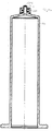
- FIG. 1 shows a section of a syringe body 1, which includes a syringe cone 3, with a distal opening 5. It is shown by the entire syringe body 1, only the upper part of the syringe in the region of the syringe cone 3.
- the syringe body 1 preferably consists of a hard plastic, for example a cycloolefin copolymer (COC) or a cycloolefin polymer (COP).
- COC cycloolefin copolymer
- COP cycloolefin polymer
- To the syringe cone 3 is a connection 10 for connectors, for example. Attachments of syringes arranged. In the present case, the connection 10 is an attachment with an internal thread 12, without being limited thereto.
- the terminal 10 is presently formed opposite the syringe body 3 as an independent component.
- the syringe body as the first component and the connection as a second component are in the illustrated embodiments according to FIG. 1
- the connection 10 is placed on the syringe body and latched in an undercut 14, ie the connection is held in a form-fitting manner.
- the separate component 10 can either be screwed or pressed into the undercut 14.
- the area of the connection is molded around, for example with a plastic. The encapsulation of the connection of the component 10 is stabilized on the syringe body.
- the material of the terminal 10 is softer than the material of the syringe body according to the invention.
- the modulus of elasticity of the syringe body made of a hard material is preferably 2500-3500 MPa, the modulus of elasticity of the connection made of a soft material is 1200-2500 MPa. In general, the modulus of elasticity of the terminal 10 is 10 to 60% less than the modulus of elasticity of the syringe body. While a cycloolefin copolymer or cycloolefin polymer is used as the material of the syringe body, the soft material of the terminal is a thermoplastic elastomer (TPE) or an elastomer or. Polypropylene (PP) or polyethylene (PE).
- TPE thermoplastic elastomer
- PP polypropylene
- PE polyethylene
- FIG. 1c is a plan view of the syringe body 1. Same components as in Figure 1a - 1b bear the same reference numbers. Hard materials such as cycloolefin polymers (COP) or cycloolefin copolymers (COC) have a low impact strength of less than 2 kJ / m 2 .
- COP cycloolefin polymers
- COC cycloolefin copolymers
- FIG. 2a-2c an alternative embodiment of a mechanical connection of a port 100 on a syringe body 101 is shown.
- the fitting 100 is made of a softer material such as a thermoplastic elastomer, an elastomer, polycarbonate, polypropylene or polyethylene compared to the hard material of the syringe body of the COC or COP may be.
- the connector 100 is characterized in that in addition to the internal thread 112 it has a peripheral cap 114 with a cavity 116, wherein in the cavity 116 projections or elevations 110 of the syringe body 101, can engage. By pressing the connection, this can be held on the cavity 116 on the syringe body 101.
- FIG. 2a The detailed configuration of the connecting piece 100 of the syringe body is in FIG. 2a shown.
- the syringe body 101 as in FIG. 2b shown consists of a hard material, for example. COC and has a syringe cone 103 with a distal opening 105 on.
- the syringe body 101 has a circumferential elevation 110.
- the cavities 116 of the connecting piece 100 engage according to FIG. 2a and are held, for example, by pressing after placing the connector on the elevations 110.
- FIG. 2b shows the complete syringe body 101 with attached connector 110. Same components as in FIG. 2a bear the same reference numbers. This also applies to the top view Figure 2c to.
- FIG. 3a1 to 3c shows the connection of the connection with the syringe body by material connection, eg. By welding.
- FIG. 3a1 shows a view of a syringe body 201 according to the invention with a mounted on the syringe body 201 fitting 210.
- the syringe body of the FIG. 3a it is a plastic syringe made of a hard material, for example. Cycloolefin (COC) or Cycloolefinpolymere (COP).
- the syringe body 201 in turn comprises a distal tip 203 with a distal opening 205.
- the connector 210 is arranged with an internal thread 212 for screwing in a connector.
- the fitting 210 is made of a softer material than the syringe body 201, for example, polyethylene or polypropylene or COC-E.
- the soft material can also be used in sections. Then it is preferably used where high forces occur when screwing the connectors.
- FIG. 3a2 is the area in detail FIG. 3a1 which shows the connection between the separate connection piece 210 and the syringe body 201.
- This connection can be made selectively or over the entire support surface.
- the separate fitting 210 made of a soft material is brought into abutment with projections 212 of the syringe body.
- the connecting piece 210 with the syringe body cohesively ie materially connected, for example by welding, in particular by ultrasonic welding.
- the fitting 210 or the syringe body 201 has material projections 220 which are vibrated with a sonotrode and thus fused.
- the ultrasonic welding can be done selectively or areally. If you work with Materialvoren 220, the welding takes place selectively. In heated ultrasonic welding, the choice of materials, especially your combination, is important. If the melting points are too far apart, a combination of different materials is no longer possible.
- FIG. 3b is again shown in great detail the entire syringe body 210 with ultrasonically welded fitting 210.
- Figure 3c shows a plan view of the embodiment according to Figure 3a1 - 3a2 , The same components are identified by the same reference numerals.
- connection piece instead of connecting the connection piece to the syringe body by welding, in particular ultrasonic welding, the complete syringe body with connection piece can be produced by a multi-component injection molding method. This is in the FIGS. 4a-4b for a first embodiment and in Fig. 5a - 5d for a second embodiment.
- FIG. 4a shows the syringe body 301 produced with multi-component injection molding.
- the syringe body 301 in turn comprises a connection piece 310 in the area of the syringe cone 303 with an internal thread 312 made of a softer material than the syringe body 301.
- the softer material is characterized by the modulus of elasticity as indicated above.
- FIG. 4b shows an overall view of the syringe FIG. 4a
- the material of the syringe body 301 is a hard plastic material, for example. COC or COP, whereas the material of the connector 310 is a soft material, eg.
- FIGS. 5a to 5d A second embodiment of a syringe body 401 produced by multi-component injection molding is shown.
- the connecting piece 410 in the region of the syringe body 401 is again made of a softer material.
- the softer material has a modulus of elasticity 10-60% lower than the hard material of the syringe body is characteristic of the second embodiment, that the syringe body 401 has a circumferential receptacle 420 in the region of the lid 421 of the syringe body.
- the fitting made of a soft material engages in the receptacle.
- a larger contact surface is provided, which allows better adhesion of the materials to each other.
- the design also shows a connection of the soft material in the cone area which causes a reduction in the force peaks that occur there.
- the soft material of the fitting also encloses the syringe cone 403 of the syringe 400 on the outside 405. Also well visible is the thread 412.
- Fig. 5b shows the entire syringe with fitting 410
- FIG. 5c the top view
- FIG. 5d a three-dimensional view. Same components as in FIG. 5a are assigned the same reference numbers.
- the entire injection molded part is made from two different plastics.
- the injection molding machine comprises two injection units, but only one closing unit is needed.
- the component produced by a multi-component injection molding method according to Figure 4a-5d Can be produced inexpensively with only one tool, in only one operation.
- geometries can be implemented that would not be possible with a mounting.
- a syringe body is provided for the first time, in which it is possible, a variety of different connectors with a To connect connecting piece, wherein the insertion torque can vary in a wide range, without the thread passes on the mechanical stresses on the syringe body and there leads to leaks.
- the materials are selected so that they do not change in contact with pharmaceutical media. Due to the softer material of the connector, the friction coefficient between the connector and the syringe is met, so that the thread can not be over-tightened.
Landscapes
- Health & Medical Sciences (AREA)
- Engineering & Computer Science (AREA)
- Public Health (AREA)
- Veterinary Medicine (AREA)
- Vascular Medicine (AREA)
- Heart & Thoracic Surgery (AREA)
- General Health & Medical Sciences (AREA)
- Life Sciences & Earth Sciences (AREA)
- Animal Behavior & Ethology (AREA)
- Hematology (AREA)
- Biomedical Technology (AREA)
- Anesthesiology (AREA)
- Mechanical Engineering (AREA)
- Manufacturing & Machinery (AREA)
- Chemical & Material Sciences (AREA)
- Chemical Kinetics & Catalysis (AREA)
- Surgery (AREA)
- Epidemiology (AREA)
- Infusion, Injection, And Reservoir Apparatuses (AREA)
- Materials For Medical Uses (AREA)
Abstract
Description
- Die Erfindung betrifft eine Spritze mit einem Spritzenkörper sowie einem Spritzenkonus, der eine distale Öffnung umfasst und einen, im Bereich des Spritzenkonus angeordneten Anschluss, insbesondere in Form eines Gewindes, wobei der Spritzenkörper aus einem ersten Material und der Anschluss aus einem zweiten Material besteht.
- Aus einer Vielzahl von Patenten sind Spritzen bekannt geworden, die einen Anschluss für unterschiedliche Konnektoren, die manuell auf die Spitze der Spritze montiert werden, aufweisen.
- Eine derartige Spritze zeigt bspw. die
US 2013/ 079 276 A . Aus derUS 2013/079 276 A ist ein Spritzenkörper bekannt geworden, bei dem eine Transportkappe, ein intravenöser Port oder eine Injektionsnadel in ein Gewinde oberhalb des Spritzenkonus eingeschraubt werden kann. Wird bspw. eine Transportkappe in das Gewinde eingeschraubt, so kann der Spritzenkonus geschützt werden. - Aus der
DE 202 158 07 U1 ist eine Spritze mit einem Gewinde im Bereich des Luer-Lock-Anschlusses bekannt geworden, wobei das Gewinde, Teil des Spritzenkörpers ist. Der Luer-Lock-Anschluss gemäß derDE 202 158 07 U1 weist ein Innengewinde auf, das im Bereich des Spritzenkonus angeordnet ist. - Die
DE 692 26 166 T2 zeigt ebenfalls eine Kunststoffspritze, wobei das Nadelanschlussstück die Form eines standardmäßigen Luer-Lock-Anschlusses mit einem Luer-Kegel und einer Außenwand mit einem Schraubgewinde um ihre innere Umfangswand aufweist. - Eine ähnliche Anordnung ist auch aus der
EP 1 080 742 A1 oder derEP 1 410 819 A1 bekannt geworden. Sowohl bei derEP 1 080 742 A1 wie bei derEP 1 410 819 A1 ist das Gewinde, das als Anschluss für Konnektoren dient, ein Teil des Luer-Konus. Ähnliche Systeme, bei denen Teile des Luer-Konus mit einem Innengewinde des Anschluss für Konnektoren bzw. Spritzennadeln etc. vorgesehen sind, zeigen dieEP 1 923 086 A1 und dieEP 3 042 689 A1 . - Aus der
WO 2012/116 790 A1 ist eine Spritze mit einem Spritzenzylinder und einem an einem distalen Ende des Spritzenzylinders vorgesehene Nadelansatzstück bekannt geworden, wobei die Spritze einen Verschluss aufweist, der eine das Nadelansatzstück dichtend verschießende Verschlusskappe und eine Sicherungskappe umfasst, wobei die Sicherungskappe die Verschlusskappe umgreift und über einen Haltering an dem Nadelansatzstück befestigt ist. Die Spritze zeichnet sich dadurch aus, dass zumindest die Sicherungskappe und die Verschlusskappe einstückig ausgebildet sind. - Zwar ist in der
WO 2012/116 790 A1 die Rede davon, dass der Haltering aus einem thermoplastischen Elastomer (TPE) oder aus Polypropylen wie auch die Verschlusskappe und der Sicherungsring gefertigt sein kann. An der anderen Seite umfasst das Nadelansatzstück bevorzugt Glas bzw. besteht aus diesem. Eine Ausgestaltung des Nadelansatzstückes sowie der Spritze aus einem harten Kunststoffmaterial, umfassend ein Cycloolefincopolymer (COC) oder Cycloolefinpolymer (COP), zeigt dieWO 2012/116 790 A1 nicht. - Bei der Verwendung von COC oder COP als Material für den Spritzenzylinder besteht das Problem, dass mechanische Spannungen zwischen dem Anschluss bzw. dem Gewinde und dem in das Gewinde eingeschraubten Gegengewinde, das dem Konnektor zugeordnet ist, Risse im Material des Spritzenkörpers entstehen können, wodurch die Funktionalität der Spritze beeinträchtigt wird. Im schlimmsten Fall führen derartige mechanische Spannungen zu Beschädigungen der Spritze selbst oder deren Undichtigkeit. Dies ist beispielsweise dann der Fall, wenn als Material des Spritzenkörpers COC (Cycloolefincopolymer) oder COP (Cycloolefinpolymer) gewählt werden.
- Zwar zeigen die
US 8,038,182 B1 und dieEP 0 838 229 A2 auch Spritzenkörper aus COC. Um eine Beschädigung des Spritzenkörpers aus COC zu vermeiden, schlägt dieUS 8,038,182 B2 eine aufwändige Konstruktion des Anschlusses, der in das Gewinde des Luer-Lock eingebracht wird, vor, bei dem nach oben und nach unten gerichtete Kräfte im Anschlussgewinde dazu führen, dass sich der Anschluss in einen Freiraum ausdehnt und radiale Kräfte auf den Spritzenkörper, die zu einem Bruch führen könnten, vermieden werden. Bei derEP 0 838 229 A2 wird ein Bruch durch Einbringen eines Halteelements verhindert. - Nachteilig an sämtlichen Ausgestaltungen gemäß dem Stand der Technik war, dass das Anschlussstück, bspw. das Gewinde des Luer-Lock dasselbe Material aufwies, wie die Spritze selbst. Dies hat dazu geführt, dass mechanische Spannungen zwischen dem Anschluss, bspw. dem Gewinde und dem in das Gewinde eingeschraubten Gegengewinde, das dem Konnektor zugeordnet ist, zu Rissen im Material des Spritzenkörpers geführt haben, wodurch die Funktionalität der Spritze beeinträchtigt wird. Im schlimmsten Fall können derartige mechanische Spannungen zu Beschädigungen der Spritze selbst und zu deren Undichtigkeit führen. Dies war insbesondere dann der Fall wenn das Material des Spritzenkörpers ein hartes Material war, beispielsweise COC (Cycloolefin Copolymer) oder COP (Cycloolefinpolymer und die Konnektoren aus einem anderen Material wie PC (Polycarbonate), PVC (Polyvenylchlorid), PE (Polyethylen) oder PA (Polyamid) bestanden.
- Ist der gesamte Spritzenkörper aus einem weicheren Kunststoffmaterial, um die Rissproblematik zu vermindern, so ergibt sich das Problem, dass zwar ein Spritzenkörper aus Polypropylen (PP) die Spannungen durch die Konnektoren aufgrund der Materialeigenschaften kompensieren kann, jedoch kann in einem Spritzenkörper aus Polypropylen (PP) ein pharmazeutisches Medium aufgrund des Diffusionsverhaltens nicht über mehrere Monate gelagert werden.
- Ein weiteres Problem besteht darin, dass Konnektoren, die bspw. in das Gewinde des Luer-Locks eingeschraubt werden sollen, eine Vielzahl unterschiedlicher Materialien wie PC, PVC, Polyethylen (PE) umfassen, die mit dem Material des Gewindes des Luer-Locks verbunden werden. Ein weiteres Problem, der derzeitigen Konnektoren, ist darin zu sehen, dass sie in der Regel manuell in das Gewinde eingedreht werden und das Eindrehmoment über einen breiten Bereich von beispielsweise 12Ncm bis 56Ncm bevorzugt 12Ncm bis 80Ncm schwanken kann. Diese Spannungen führen dazu, dass entweder am Gewinde oder am Konnektor Risse entstehen. Im schlimmsten Fall können sogar Brüche aufgrund dieser Spannungen entstehen.
- Aufgabe der Erfindung ist es daher, die Nachteile des Standes der Technik zu überwinden und insbesondere, eine Spritze anzugeben, die das Aufbringen, bzw. den Anschluss unterschiedlichster Konnektoren ermöglicht, ohne das Defekte am Material des Spritzenkörpers auftreten.
- Erfindungsgemäß wird diese Aufgabe durch eine Spritze mit den Merkmalen des Anspruches 1 gelöst.
- Bei einem erfindungsgemäßen Spritzenkörper mit einem Spritzenkonus der eine distale Öffnung umfasst und einen in Bereich des Spritzenkonus angeordneten Anschluss sind die Materialien von Anschluss und Spritzenkörper unterschiedlich. Dabei besteht der Spritzenkörper aus einem ersten Material und der Anschluss, insbesondere das Gewinde, wenigstens abschnittsweise aus einem zweiten Material. Erfindungsgemäß ist das zweite Material ein weicheres Material als das erste Material. Das zweite Material kann ein thermoplastisches Elastomer (TPE), ein Elastomer oder Polypropylen (PP), Polycarbonat (PC), Polyethylen (PE), Polyamid (PA) oder COC-E sein, das sich dadurch auszeichnet, dass es eine höhere Kerbschlagfestigkeit und/oder einen geringeren
E-Modul aufweist. Das zweite weiche Material wird bevorzugt dort eingesetzt, wo beim Einschrauben beispielsweise von Konnektoren in den Anschluss hohe Kräfte auftreten. Dann ist auch eine abschnittsweise Ausbildung möglich an dem Orten der hohen Kräfte. - In vorliegender Anmeldung wird unter einem weicheren Material, ein Material verstanden, dessen E-Modul um 10 bis 60 % geringer ist als derjenige des harten Materials. Bevorzugt liegt der E-Modul des ersten harten Materials im Bereich von größer 2500 bis 3500 MPa, bevorzugt 2700 bis 3200 MPa, und der des weicheren zweiten Materials im Bereich von1200 bis 2500 MPa, bevorzugt 1500 bis 1800 MPa.
- Des Weiteren zeichnet sich das zweite weiche Material durch eine hohe Kerbschlagfestigkeit größer 2kJ/m2 aus.
- Unter Kerbschlagfestigkeit wird ein Maß für die Widerstandsfähigkeit eines Werkstoffs gegen eine schlagartige (dynamische) Beanspruchung verstanden. Die Einheit ist die geleistete Kerbschlagarbeit bezogen auf die Bruchfläche in Joule pro Flächeneinheit [J/cm2]. Generell haben weiche Materialien eine hohe Kerbschlagfestigkeit, wohingegen harte Materialien, Materialien mit niedriger Kerbschlagfestigkeit sind. Sprödere Materialien wie COC haben eine Kerbschlagfestigkeit kleiner 2kJ/m2.
- Dadurch, dass im Bereich des Anschlusses, d.h. insbesondere des Gewindes, ein weicheres Material verwendet wird, als für den Spritzenkörper selbst, ist es möglich, dass das weichere Material Belastungen und Kraftspitzen, die beim Einschrauben eines Konnektors oder Adapters in das Gewinde auftreten können, auffängt und diese nicht an den Spritzenkörper weitergegeben werden. Durch die Verwendung eines weichen Kunststoffmaterials ist es möglich, unterschiedliche Belastungsfälle zu kompensieren, wie bspw. Kraftspitzen, Drehmomente, etc. Bevorzugt weist der Anschluss in der Geometrie die Geometrie eines Luer-Lock-Adapters (LLA) auf. Dies stellt sicher, dass eine Standardspritze zur Verfügung gestellt wird, die mit den unterschiedlichsten Anschlusselementen insbesondere Konnektoren und Adaptern zusammenwirken kann.
- Das weichere Material im Bereich des Anschlusses, insbesondere des Gewindes, kann zwar nicht verhindern, dass mechanische Belastungen auftreten, jedoch stellt das weichere Material einen Puffer zur Verfügung, um Kraftspitzen bspw. beim Eindrehen des Konnektors abzufangen und gleichmäßig über den Spritzenkörper zu verteilen. Das weiche Material stellt somit eine Art Puffer dar. Möglich ist es, dass das weiche Material sowohl die Gewindegeometrie darstellt, als auch zwischen das Gewinde des Konnektors und das Gewinde des Spritzenkörpers, der als Anschluss dient, als Puffer eingebracht wird.
- Das erste, harte Material des Spritzenkörpers ist bevorzugt ein Cycloolefincopolymer (COC) oder ein Cycloolefinpolymere (COP). Der Vorteil der Verwendung des Cycloolefincopolymer oder des Cycloolefinpolymere ist, dass diese Materialien eine hohe Wasserdampfbarriere darstellen, die es ermöglicht, Flüssigkeiten, insbesondere flüssige Arzneimittel über einen längeren Zeitraum, der mehrere Jahre betragen kann, ohne bzw. mit sehr geringem Volumenverlust zu lagern.
- Die Erfinder haben herausgefunden, dass dann wenn COC und COP als Materialien für den Spritzenkörper verwendet werden, die Problelmatik der Rissbildung verhindert werden kann, wenn der Anschluss für die Konnektoren, bspw. der Luer-Lock aus einem weicheren Material als der Spritzenkörper gefertigt ist. Durch die Verwendung eines weicheren Materials kann erreicht werden, dass auch bei hohen Eindrehmomenten Spannungen am Gewinde oder am Konnektor und damit Brüche aufgrund dieser Spannungen in der Spritze vermieden werden.
- Als weicheres, zweites Material wird bevorzugt ein Elastomer, insbesondere ein thermoplastisches Elastomer (TPE) oder COC-E verwendet. Andere mögliche Polymere können auch Polypropylen (PP), Polyethylen (PE), Polycarbonat (PC), Polyamid (PA) sein.
- Um die Spritze im Bereich von pharmazeutischen Produkten einsetzen zu können, ist es notwendig, dass sowohl das erste, wie auch das zweite Material des Spritzenkörpers bzw. des Anschlusses, Materialien umfasst, die bei Temperaturen > 100°C, insbesondere 121°C, insbesondere maximal 180°C, sterilisierbar sind. Beispiele für derartige Materialien sind für den Spritzenkörper COC oder COP und für den Konnektor COC-E, TPE, PP, PE, PC oder PA.
- Besonders bevorzugt ist es, wenn der Spritzenkörper ein erstes Bauteil der Spritze darstellt und der Anschluss, insbesondere das Gewinde und unter Umstände auch der Konus, ein zweites Bauteil. Erstes Bauteil und zweites Bauteil sind getrennte Bauteile, die verbunden werden müssen, z.B. durch Schweißen. Die Verbindung von erstem und zweitem Bauteil kann aber auf unterschiedliche Art und Weise erfolgen. Möglich wären eine mechanische und/oder eine stoffschlüssige und/oder eine reibschlüssige und/oder eine formschlüssige Verbindung.
- Besonders bevorzugt ist es, wenn die Verbindung zwischen Spritzenkörper und Anschluss derart ausgestaltet ist, dass das erste Bauteil mit dem zweiten Bauteil zwar verbunden ist, diese Verbindung aber bei einer vorbestimmten Kraft, gelöst werden kann, d.h. das erste Bauteil mit dem zweiten Bauteil definiert lösbar verbunden ist. Bei einer derartigen Anordnung wird bei eindeutiger Überbelastung ein sichtbarer Bruch an einer definierten Stelle ausgelöst anstatt an einer kritischen Position, z.B. Dichtstelle, die nicht eingesehen werden kann.
- Bei der Herstellung einer erfindungsgemäßen Spritze sind unterschiedliche Möglichkeiten denkbar. Ein erstes Verfahren zeichnet sich dadurch aus, dass der Spritzenkörper aus einem ersten Material und der Anschluss, insbesondere das Gewinde, aus einem zweiten Material ist, wobei das zweite Material weicher als das erste Material ist, und erstes und zweites Material getrennt zur Verfügung gestellt werden. In einem weiteren Verfahrensschritt werden der Anschluss und der Spritzenkörper miteinander verbunden, und zwar materialschlüssig und/oder reibschlüssig und/oder formschlüssig und/oder stoffschlüssig. Besonders bevorzugt ist bei einem stoffschlüssigen Verbund wenn Spritzenkörper und Anschluss durch Schweißen, insbesondere Ultraschall-Schweißen verbunden werden.
- Alternativ zu dem erstgenannten Herstellverfahren, bei dem jede Komponente einzeln hergestellt wird, ist es auch möglich, dass gesamte Bauteil also die Spritze mit Spritzenkörper und Anschluss durch Mehrkomponenten-Spritzgießen herzustellen. Beim Mehrkomponenten-Spritzgießen wird ein Spritzgussteil erhalten, das aus zwei oder mehreren unterschiedlichen Kunststoffen besteht. Beim Mehrkomponenten-Spritzgießen sind unterschiedliche Verfahren denkbar. Eine Spritzgießmaschine für Mehrkomponenten-Spritzgießen umfasst zwei oder mehreren Spritzeinheiten aber nur eine Schließeinheit. Zudem kann auch ein vorgespritztes Teil in ein Werkzeug zur Umspritzung eingelegt werden. Beim Mehrkomponenten-Spritzgießen können die entsprechenden Bauteile kostengünstig mit nur einem Werkzeug in einem Arbeitsgang hergestellt werden. Zudem können durch Mehrkomponenten-Spritzgießen geringere Lagetoleranzen umgesetzt werden als bei der Montage.
- Mit dem Mehrkomponenten-Spritzgießen ist es möglich, dass das weiche Material an das harte Material oder umgekehrt angespritzt wird. Dies erspart den Vorgang der Montage und führt zu einer physikalischen Anbindung zwischen dem harten und weichen Material. Beim Mehrkomponenten-Spritzgießen ist es möglich, dass zwischen dem weichen und dem harten Material die Anbindung eingestellt werden kann, so dass der Anschluss lösbar auf dem Spritzenkörper angebracht wird.
- Besonders bevorzugt ist es, wenn das weichere Material ein erhöhten Reibungskoeffizienten aufweist, der dazu führt, dass das Gewinde nicht überdreht werden kann. Bei der Anbindung des ersten an das zweite Material sollte die Verbindungsfläche so ausführbar sein, dass ein möglichst großer Oberflächenkontakt der beiden Materialien die Stabilität der Verbindung gewährleistet.
- Die Erfindung soll nachfolgend anhand der Figuren beispielhaft beschrieben werden. Es zeigen:
- Fig. 1a-1c
- eine erste Version einer mechanischen Befestigung des Anschlusses am Spritzenkörper
- Fig.2a-2c
- eine zweite Version einer mechanischen Befestigung des Anschlusses am Spritzenkörper
- Fig.3a1-3c
- eine Version mit Spritzenkörper und Anschluss als Einzelteile, wobei die Einzelteile Ultraschall verschweißt sind
- Fig.4a-4b
- erste Ausführungsform eines Anschlusses und Spritzenkörper erstellt mittels Mehrkomponenten-Spritzgießen
- Fig. 5a-5d
- zweite Ausführungsform eines Anschlusses und Spritzenkörpers erstellt mittels Mehrkomponenten Spritzgießen
-
Figur 1 zeigt einen Ausschnitt, eines Spritzenkörpers 1, der einen Spritzenkonus 3 umfasst, mit einer distalen Öffnung 5. Es ist vom gesamten Spritzenkörper 1 nur der obere Teil der Spritze im Bereich des Spritzenkonus 3 gezeigt. Der Spritzenkörper 1 besteht bevorzugt aus einem harten Kunststoff bspw. einem Cycloolefincopolymere (COC) oder einem Cycloolefinpolymere (COP). Um den Spritzenkonus 3 ist ein Anschluss 10 für Konnektoren bspw. Aufsätze von Spritzen angeordnet. Bei dem Anschluss 10 handelt es sich vorliegend um einen Aufsatz mit einem Innengewinde 12, ohne hierauf beschränkt zu sein. Der Anschluss 10 ist vorliegend gegenüber dem Spritzenkörper 3 als eigenständiges Bauteil ausgebildet. Der Spritzenkörper als erstes Bauteil und der Anschluss als zweites Bauteil sind in den dargestellten Ausführungsformen gemäßFigur 1 lediglich mechanisch miteinander verbunden, bspw. ist der Anschluss 10 auf den Spritzenkörper aufgesetzt und in einer Hinterschneidung 14 verrastet, d.h. der Anschluss wird form- schlüssig gehalten. Das separate Bauteil 10 kann entweder in die Hinterschneidung 14 eingedreht oder aufgepresst sein. Um das Bauteil 10 besser auf dem Spritzenkörper 1 zu halten, kann vorgesehen sein, dass der Bereich des Anschlusses umspritzt wird, bspw. mit einem Kunststoff. Durch die Umspritzung wird der Anschluss des Bauteiles 10 am Spritzenkörper stabilisiert. Das Material des Anschlusses 10 ist gemäß der Erfindung weicher als das Material des Spritzenkörpers. Bevorzugt beträgt der E-Modul des Spritzenkörpers aus einem harten Material 2500-3500 MPa der E-Modul des Anschlusses aus einem weichen Material 1200-2500 MPa. Generell ist der E-Modul des weicheren Materials des Anschlusses 10 um 10 bis 60 % geringer als der E-Modul des harten Materials des Spritzenkörpers. Während als Material des Spritzenkörpers ein Cycloolefincopolymere oder Cycloolefinpolymer eingesetzt wird, handelt es sich bei dem weichen Material des Anschlusses um ein thermoplastisches Elastomer (TPE) oder ein Elastomer oder. Polypropylen (PP) oder Polyethylen (PE). Eine Kerbschlagfestigkeit (Charpy notched impact strength) von mehr als 2kJ/m2 zeichnet die angegebenen weichen Materialien aus.Figur 1c ist eine Draufsicht auf den Spritzenkörper 1. Gleiche Bauteile wie inFigur 1a - 1b tragen gleiche Bezugsziffern. Harte Materialien wie Cycloolefinpolymere (COP) oder Cycloolefincopolymere (COC) haben eine geringe Kerbschlagfertigkeit von weniger als 2kJ/m2. - In
Figur 2a-2c ist eine alternative Ausführungsform einer mechanischen Verbindung eines Anschlusses 100 auf einem Spritzenkörper 101 gezeigt. Hierbei zeigtFigur 2a das Anschlussstück 100 mit dem Innengewinde 112. Das Anschlussstück 100 besteht aus einem weicheren Material z.B. einen thermoplastischen Elastomer, einen Elastomer, Polycarbonat, Polypropylen oder Polyethylen verglichen mit dem harten Material des Spritzenkörpers der COC oder COP sein kann. Das Anschlussstück 100 zeichnet sich dadurch aus, dass neben dem Innengewinde 112 es einen umlaufenden Aufsatz 114 mit einem Hohlraum 116 aufweist, wobei in dem Hohlraum 116 Vorsprünge oder Erhebungen 110 des Spritzenkörpers 101, eingreifen können. Durch Pressung des Anschluss kann dieses über den Hohlraum 116 auf dem Spritzenkörper 101 gehalten werden. Die detaillierte Ausgestaltung des Anschlussstückes 100 des Spritzenkörpers ist inFigur 2a gezeigt. Der Spritzenkörper 101 wie inFigur 2b gezeigt, besteht aus einem harten Material, bspw. COC und weist einen Spritzenkonus 103 mit einer distalen Öffnung 105 auf. Neben dem Spritzenkonus 103 weist der Spritzenkörper 101 eine umlaufende Erhebung 110 auf. In die umlaufende Erhebung 110 greifen die Hohlräume 116 des Anschlussstückes 100 gemäßFigur 2a ein und werden z.B. durch Einpressen nach dem Aufsetzen des Anschlussstückes auf die Erhebungen 110 gehalten.Figur 2b zeigt den kompletten Spritzenkörper 101 mit aufgesetztem Anschlussstück 110. Gleiche Bauteile wie inFigur 2a tragen dieselben Bezugsziffern. Dies trifft auch auf die Draufsicht gemäßFigur 2c zu. -
Figur 3a1 bis 3c zeigt die Verbindung des Anschlusses mit dem Spritzenkörper durch Materialschluss, bspw. durch Verschweißen.Figur 3a1 zeigt eine Ansicht eines Spritzenkörpers 201 gemäß der Erfindung mit einem auf dem Spritzenkörper 201 angebrachten Anschlussstück 210. Bei dem Spritzenkörper derFigur 3a handelt es sich um eine Kunststoffspritze aus einem harten Material, bspw. Cycloolefincolymere (COC) oder Cycloolefinpolymere (COP). Der Spritzenkörper 201 umfasst wiederrum eine distale Spitze 203 mit einer distalen Öffnung 205. Um die distale Spitze 203 herum ist das Anschlussstück 210 mit einem Innengewinde 212 zum Einschrauben eines Konnektors angeordnet. Wie in den vorausgegangenen Ausführungsformen besteht das Anschlussstück 210 aus einem weicheren Material als der Spritzenkörper 201 bspw. aus Polyethylen oder Polypropylen oder COC-E. Das weiche material kann auch abschnittsweise verwandt werden. Dann wird es bevorzugt dort eingesetzt, wo beim Einschrauben der Konnektoren hohe Kräfte auftreten. - In
Figur 3a2 ist detailliert der Bereich ausFigur 3a1 dargestellt, der die Verbindung zwischen dem separaten Anschlussstück 210 und dem Spritzenkörper 201 zeigt. Diese Verbindung kann punktuell oder über die komplette Auflagefläche erfolgen. Das aus einem weichen Material bestehende separate Anschlussstück 210 wird mit Vorsprüngen 212 des Spritzenkörpers zur Anlage gebracht. Nachdem das separate Anschlussstück 210 auf den Spritzenkörper aufgesetzt wurde, wird das Anschlussstück 210 mit dem Spritzenkörper stoffschlüssig d.h. materialschlüssig verbunden, bspw. durch Schweißen, insbesondere durch Ultraschall-Schweißen. Für das Ultraschallschweißen umfassen das Anschlussstück 210 oder der Spritzenkörper 201 Materialvorhaltungen 220 besitzt, die mit einer Sonotrode zum Schwingen und damit zum Verschmelzen gebracht werden. Das Ultraschallschweißen kann punktuell oder flächig erfolgen. Wird mit Materialvorhaltungen 220 gearbeitet, so erfolgt die Verschweißung punktuell. Beim erwärmten Ultraschallschweißen ist die Auswahl der Materialien, insbesondere Ihre Kombination wichtig. Liegen die Schmelzpunkte zu weit auseinander so ist eine Verbindung der unterschiedlichen Materialien nicht mehr möglich. - In
Figur 3b ist nochmals sehr detailliert der gesamte Spritzenkörper 210 mit ultraschallverschweißtem Anschlussstück 210 gezeigt.Figur 3c zeigt eine Draufsicht auf die Ausführung gemäßFigur 3a1 - 3a2 . Gleiche Bauteile sind mit denselben Bezugsziffern gekennzeichnet. - In einer alternativen Ausgestaltung der Erfindung kann anstelle des Verbindens des Anschlussstückes mit dem Spritzenkörper durch Schweißen, insbesondere Ultraschall-Schweißen der komplette Spritzenkörper mit Anschlussstück durch ein Mehrkomponenten-Spritzgieß-Verfahren hergestellt werden. Dies ist in den
Figuren 4a - 4b für eine erste Ausführungsform und inFig. 5a - 5d für eine zweite Ausführungsform gezeigt. -
Figur 4a zeigt den mit Mehrkomponenten-Spritzgießen hergestellten Spritzenkörper 301. Der Spritzenkörper 301 umfasst wiederrum ein Anschlussstück 310 im Bereich des Spritzenkonus 303 mit einem Innengewinde 312 aus einem weicheren Material als der Spritzenkörper 301. Das weichere Material ist wie zuvor angegeben über den E-Modul charakterisiert. -
Figur 4b zeigt eine Gesamtansicht der Spritze ausFigur 4a . Das Material des Spritzenkörpers 301 ist ein hartes Kunststoffmaterial bspw. COC oder COP, wohingegen das Material des Anschlussstückes 310 ein weiches Material, bspw. - Polypropylen oder Polyethylen oder COC-E ist. Gut zu erkennen in
Figur 4a ist auch das Innengewinde des Anschlussstückes 312. Gleiche Bauteile wie inFigur 4a sind inFigur 4b mit denselben Bezugsziffern belegt. - In den
Figuren 5a bis 5d ist eine zweite Ausführungsform eines mit Mehrkomponenten Spritzgießen hergestellten Spritzenkörpers 401 gezeigt. Das Anschlussstück 410 im Bereich des Spritzenkörpers 401 besteht wieder aus einem weicheren Material. Das weichere Material weist einen um 10-60 % geringeren E-Modul auf, als das harte Material des Spritzenkörpers auf Charakteristisch für die zweite Ausführungsform ist, dass der Spritzenkörper 401 eine umlaufende Aufnahme 420 im Bereich des Deckels 421 des Spritzenkörpers aufweist. Das Anschlussstück aus einem weichen Material greift in die Aufnahme ein. Bei den Varianten gemäßFigur 5a bis 5d wird eine größere Kontaktfläche zur Verfügung gestellt, die eine bessere Haftung der Materialien aufeinander zulässt. Zudem zeigt die Ausführung auch eine Anbindung des weichen Materials im Konusbereich die einen Abbau der Kraftspitzen, die dort auftreten bewirkt.
Des Weiteren umschließt das weiche Material des Anschlussstückes auch den Spritzenkonus 403 der Spritze 400 an der Außenseite 405. Gut zu erkennen ist auch das Gewinde 412.Fig. 5b zeigt die gesamte Spritze mit Anschlussstück 410,Figur 5c die Draufsicht undFigur 5d eine dreidimensionale Aussicht. Gleiche Bauteile wie inFigur 5a sind mit denselben Bezugsziffern belegt. - Beim Mehrkomponenten-Spritzgießen wird das gesamte Spritzgussteil aus zwei unterschiedlichen Kunststoffen hergestellt. Hierfür umfasst die Spritzgrieß-Maschine zwei Spritzeinheiten, wobei aber nur eine Schließeinheit benötigt wird. Das mit einem Mehrkomponenten-Spritzgieß-Verfahren hergestellte Bauteil gemäß
Figur 4a-5d kann kostengünstig mit nur einem Werkzeug, in nur einem Arbeitsvorgang hergestellt werden. Zudem sind Geometrien umsetzbar, die bei einer Montage nicht möglich wären. - Mit der Erfindung wird erstmals ein Spritzenkörper zur Verfügung gestellt, bei dem es möglich ist, eine Vielzahl unterschiedlicher Konnektoren mit einem Anschlussstück zu verbinden, wobei das Eindrehmoment in einem breiten Bereich schwanken kann, ohne dass das Gewinde die mechanischen Belastungen an den Spritzenkörper weitergibt und dort zu Undichtigkeiten führt.
- Des Weiteren sollten sämtliche Materialien sowohl des Spritzenkörpers, wie auch des Anschlussstückes Dampf-sterilisierbar sein.
- Des Weiteren sind die Materialien so ausgewählt, dass sie sich nicht in Kontakt mit pharmazeutischen Medien verändern. Durch das weichere Material des Anschlussstückes wird der Reibungskoeffizient zwischen dem Konnektor und der Spritze erfüllt, so dass das Gewinde nicht überdreht werden kann.
- Die Erfindung umfasst Aspekte, die in nachfolgenden Sätze niedergelegt sind, die Teil der Beschreibung sind, aber keine Ansprüche in Übereinstimmung mit J15/88 der Beschwerdekammer.
- 1. Spritze mit einem Spritzenkörper (1,101,201) sowie einem Spritzenkonus (3,103,203), der eine distale Öffnung (5) umfasst
und
einen im Bereich des Spritzenkonus angeordneten Anschluss (10,100,200), insbesondere ein Gewinde (12,112,212),
wobei der Spritzenkörper (1, 101, 201) aus einem ersten Material besteht und der Anschluss (10,100,200) insbesondere das Gewinde wenigstens abschnittsweise, insbesondere vollständig, aus einem zweiten Material,
dadurch gekennzeichnet, dass
das erste Material verschieden zum zweiten Material ist und das zweite Material ein weicheres Material als das erste Material ist. - 2. Spritze nach Satz 1,
dadurch gekennzeichnet, dass,
das erste Material einen E-Modul hat und das zweite Material einen E-Modul hat der um 10 bis 60 % geringer ist als der E-Modul des ersten Materials. - 3. Spritze nach einem der Sätze 1 bis 2,
dadurch gekennzeichnet, dass
der E-Modul des ersten Materials im Bereich >2500 bis 3500 MPa, bevorzugt 2700 bis 3200 MPa und der E-Modul des zweiten Materials 1200 bis 2500 MPa, bevorzugt 1500 bis 1800 MPa liegt. - 4. Spritze nach einem der Sätze 1 bis 3,
dadurch gekennzeichnet, dass
die Kerbschlagfestigkeit des zweiten, weichen Materials größer als 2kJ/m2 ist. - 5. Spritze nach einem der Sätze1 bis 4
dadurch gekennzeichnet, dass
das erste Material ein Cycloolefincopolymer (COC) oder ein Cycloolefinpolymer (COP) ist - 6. Spritze nach einem der Sätze 1 bis 5,
dadurch gekennzeichnet, dass
das zweite Material ein thermoplastisches Elastomer (TPE), ein Elastomer, Polypropyen (PP), Polycabonat (PC), Polyethylen (PE), Polyamid (PA) oder COC-E ist. - 7. Spritze nach einem der Sätze 1 bis 6,
dadurch gekennzeichnet, dass
das erste und das zweite Material Materialien umfasst, die bei Temperaturen > 100° C, insbesondere > 121° C, insbesondere maximal 180° C, sterilisierbar sind. - 8. Spritze nach einem der Sätze 1 bis 7,
dadurch gekennzeichnet, dass
der Spritzenkörper (1, 101, 201) ein erstes Bauteil der Spritze ausbildet und der Anschluss (10,100,200), insbesondere das Gewinde (12,112,212), ein zweites Bauteil und erstes und zweites Bauteil mechanisch und/oder stoffschlüssig und/oder reibschlüssig und/oder formschlüssig und/oder definiert lösbar miteinander verbunden sind. - 9. Spritze nach einem der Sätze 1 bis 8,
dadurch gekennzeichnet, dass
der Anschluss (10, 100, 200) eine Außengeometrie aufweist und die Außengeometrie der Außengeometrie eines Luer-Lock-Adapters entspricht. - 10. Verfahren zur Herstellung einer Spritze, umfassend nachfolgende Schritte:
- ein Spritzenkörper (1,101,201) aus einem ersten Material und
- ein Anschluss (10, 100, 200), insbesondere ein Gewinde (12, 112, 212), aus einem zweiten Material, das weicher als das erste Material ist, wird zur Verfügung gestellt, wobei das zweite Material einen E-Modul aufweist, der 10 bis 60 % geringer ist als der E-Modul der erste Materials.
- Anschluss (10, 100, 200) und Spritzenkörper (1, 101, 201) werden materialschlüssig und/oder reibschlüssig und/oder formschlüssig und/oder stoffschlüssig miteinander verbunden.
- 11. Verfahren nach Satz 10,
dadurch gekennzeichnet, dass
Spritzenkörper und Anschluss stoffschlüssig durch Schweißen, insbesondere Ultraschweißen, miteinander verbunden werden. - 12. Verfahren zur Herstellung einer Spritze mit einem Spritzenkörper aus einem ersten Material und einem Anschluss, insbesondere einem Gewinde aus einem zweiten Material, das weicher als das erste Material ist, wobei das zweite Material einen E-Modul aufweist, der 10 bis 60 % geringer als der E-Modul des ersten Materials ist,
dadurch gekennzeichnet, dass
die Spritze durch Mehrkomponenten-Spritzgießen erhalten wird. - 13. Verfahren nach Satz 12,
dadurch gekennzeichnet, dass
das Mehrkomponenten-Spritzgießen derart geführt wird, dass der Anschluss ab einer Belastung von wenigstens 25 Ncm, insbesondere wenigstens 35 Ncm definiert lösbar ist.
Claims (12)
- Spritze mit einem Spritzenkörper (1,101,201) sowie einem Spritzenkonus (3,103,203), der eine distale Öffnung (5) umfasst
und
einen im Bereich des Spritzenkonus angeordneten Anschluss (10,100,200), insbesondere ein Gewinde (12,112,212),
wobei der Spritzenkörper (1,101,201) aus einem ersten Material besteht und der Anschluss (10,100,200) insbesondere das Gewinde wenigstens abschnittsweise, insbesondere vollständig, aus einem zweiten Material, wobei das erste Material verschieden zum zweiten Material ist und das zweite Material ein weicheres Material als das erste Material ist,
dadurch gekennzeichnet, dass
das erste Material ein Cycloolefincopolymer (COC) oder ein Cycloolefinpolymer (COP) ist. - Spritze nach Anspruch 1,
dadurch gekennzeichnet, dass,
das erste Material einen E-Modul hat und das zweite Material einen E-Modul hat der um 10 bis 60 % geringer ist als der E-Modul des ersten Materials. - Spritze nach einem der Ansprüche 1 bis 2,
dadurch gekennzeichnet, dass
der E-Modul des ersten Materials im Bereich >2500 bis 3500 MPa, bevorzugt 2700 bis 3200 MPa und der E-Modul des zweiten Materials 1200 bis 2500 MPa, bevorzugt 1500 bis 1800 MPa liegt. - Spritze nach einem der Ansprüche 1 bis 3,
dadurch gekennzeichnet, dass
die Kerbschlagfestigkeit des zweiten, weichen Materials größer als 2kJ/m2 ist. - Spritze nach einem der Ansprüche 1 bis 4,
dadurch gekennzeichnet, dass
das zweite Material ein thermoplastisches Elastomer (TPE), ein Elastomer, Polypropyen (PP), Polycabonat (PC), Polyethylen (PE), Polyamid (PA) oder COC-E ist. - Spritze nach einem der Ansprüche 1 bis 5,
dadurch gekennzeichnet, dass
das erste und das zweite Material Materialien umfasst, die bei Temperaturen > 100° C, insbesondere > 121° C, insbesondere maximal 180° C, sterilisierbar sind. - Spritze nach einem der Ansprüche 1 bis 5,
dadurch gekennzeichnet, dass
der Spritzenkörper (1, 101, 201) ein erstes Bauteil der Spritze ausbildet und der Anschluss (10,100,200), insbesondere das Gewinde (12,112,212), ein zweites Bauteil und erstes und zweites Bauteil mechanisch und/oder stoffschlüssig und/oder reibschlüssig und/oder formschlüssig und/oder definiert lösbar miteinander verbunden sind. - Spritze nach einem der Ansprüche 1 bis 7,
dadurch gekennzeichnet, dass
der Anschluss (10, 100, 200) eine Außengeometrie aufweist und die Außengeometrie der Außengeometrie eines Luer-Lock-Adapters entspricht. - Verfahren zur Herstellung einer Spritze, umfassend nachfolgende Schritte:- ein Spritzenkörper (1,101,201) aus einem ersten Material und- ein Anschluss (10, 100, 200), insbesondere ein Gewinde (12, 112, 212), aus einem zweiten Material, das weicher als das erste Material ist, wird zur Verfügung gestellt, wobei das zweite Material einen E-Modul aufweist, der 10 bis 60 % geringer ist als der E-Modul der erste Materials, wobei das erste Material ein Cycloolefincopolymer (COC) oder ein Cycloolefinpolymer (COP) ist,- der Anschluss (10, 100, 200) und der Spritzenkörper (1, 101, 201) werden materialschlüssig und/oder reibschlüssig und/oder formschlüssig und/oder stoffschlüssig miteinander verbunden.
- Verfahren nach Anspruch 9,
dadurch gekennzeichnet, dass
Spritzenkörper und Anschluss stoffschlüssig durch Schweißen, insbesondere Ultraschweißen, miteinander verbunden werden. - Verfahren zur Herstellung einer Spritze mit einem Spritzenkörper aus einem ersten Material und einem Anschluss, insbesondere einem Gewinde aus einem zweiten Material, das weicher als das erste Material ist, wobei das zweite Material einen E-Modul aufweist, der 10 bis 60 % geringer als der E-Modul des ersten Materials ist,
dadurch gekennzeichnet, dass
die Spritze durch Mehrkomponenten-Spritzgießen erhalten wird und das erste Material ein Cycloolefincopolymer (COC) oder ein Cycloolefinpolymer (COP) ist. - Verfahren nach Anspruch 11,
dadurch gekennzeichnet, dass
das Mehrkomponenten-Spritzgießen derart geführt wird, dass der Anschluss ab einer Belastung von wenigstens 25 Ncm, insbesondere wenigstens 35 Ncm definiert lösbar ist.
Applications Claiming Priority (1)
| Application Number | Priority Date | Filing Date | Title |
|---|---|---|---|
| DE102017200007.4A DE102017200007A1 (de) | 2017-01-02 | 2017-01-02 | Spritze mit unterschiedlichen Materialien |
Publications (2)
| Publication Number | Publication Date |
|---|---|
| EP3342441A1 true EP3342441A1 (de) | 2018-07-04 |
| EP3342441B1 EP3342441B1 (de) | 2022-08-31 |
Family
ID=60320775
Family Applications (1)
| Application Number | Title | Priority Date | Filing Date |
|---|---|---|---|
| EP17201549.7A Active EP3342441B1 (de) | 2017-01-02 | 2017-11-14 | Spritze mit unterschiedlichen materialien |
Country Status (6)
| Country | Link |
|---|---|
| US (2) | US20180207324A1 (de) |
| EP (1) | EP3342441B1 (de) |
| JP (2) | JP7053250B2 (de) |
| KR (1) | KR102389743B1 (de) |
| CN (2) | CN117861017A (de) |
| DE (1) | DE102017200007A1 (de) |
Cited By (2)
| Publication number | Priority date | Publication date | Assignee | Title |
|---|---|---|---|---|
| WO2021214192A1 (de) | 2020-04-24 | 2021-10-28 | Fresenius Kabi Deutschland Gmbh | Spritze und spritzenkörper |
| WO2021214193A1 (de) | 2020-04-24 | 2021-10-28 | Fresenius Kabi Deutschland Gmbh | Spritze, spritzenkörper sowie verfahren zu dessen herstellung |
Families Citing this family (3)
| Publication number | Priority date | Publication date | Assignee | Title |
|---|---|---|---|---|
| DE102018121835A1 (de) * | 2018-09-07 | 2020-03-12 | Gerresheimer Regensburg Gmbh | Verfahren und Vorrichtung zur Herstellung eines hohlförmigen Spritzgussteils |
| CN110375067B (zh) | 2019-06-25 | 2024-06-14 | 北京北分瑞利分析仪器(集团)有限责任公司 | 一种应用于注射器的活塞密封结构 |
| WO2023209520A1 (en) * | 2022-04-26 | 2023-11-02 | Pfizer Inc. | Multi-layered syringe with a threaded connection part and method of manufacturing same |
Citations (14)
| Publication number | Priority date | Publication date | Assignee | Title |
|---|---|---|---|---|
| EP0838229A2 (de) | 1996-10-28 | 1998-04-29 | Daikyo Seiko, Ltd. | Spritze mit einem luer-lock Teil |
| DE69226166T2 (de) | 1991-01-15 | 1998-12-03 | Astra Pharmaceuticals Pty. Ltd., North Ryde | Kunststoffspritze |
| EP1080742A1 (de) | 1998-03-27 | 2001-03-07 | Bracco International B.V. | Spritzenzylinder aus kunststoff sowie verfahren zu seiner verbesserung |
| DE20215807U1 (de) | 2002-10-15 | 2003-01-02 | Transcoject Gesellschaft für medizinische Geräte mbH & Co KG, 24539 Neumünster | Spritzenzylinder |
| EP1410819A1 (de) | 2002-10-15 | 2004-04-21 | TRANSCOJECT GESELLSCHAFT FÜR MEDIZINISCHE GERÄTE mbH & CO. KG | Originalitätsverschluss für eine Spritze |
| US20060106349A1 (en) * | 2002-10-24 | 2006-05-18 | Terumo Kabushiki Kaisha | Syringe, cap and method of producing prefilled syringe |
| JP2006166961A (ja) * | 2004-12-13 | 2006-06-29 | Nipro Corp | 接続具 |
| EP1923086A1 (de) | 2006-11-15 | 2008-05-21 | Arte Corporation | Zylindrische Luer-Lock-Spritzenspitze |
| JP2008246070A (ja) * | 2007-03-30 | 2008-10-16 | Terumo Corp | プレフィルドシリンジ |
| US8038182B2 (en) | 2006-07-18 | 2011-10-18 | Mallinckrodt Llc | Breakage resistant fitting |
| WO2012116790A1 (de) | 2011-03-03 | 2012-09-07 | Vetter Pharma-Fertigung GmbH & Co. KG | Verschluss für eine spritze und herstellungsverfahren |
| US20130079276A1 (en) | 2010-03-26 | 2013-03-28 | N.V. Nurticia | Low protein infant formula with increased essential amino acids |
| US20140025017A1 (en) * | 2011-04-20 | 2014-01-23 | Taiji Horita | Barrel with cap, pre-filled syringe, and cap with connector |
| EP3042689A1 (de) | 2013-09-02 | 2016-07-13 | Taisei Kako Co., Ltd. | Spritze und spritzenset |
Family Cites Families (15)
| Publication number | Priority date | Publication date | Assignee | Title |
|---|---|---|---|---|
| US4220151A (en) * | 1978-09-20 | 1980-09-02 | Sherwood Medical Industries Inc. | Disposable Luer lock syringe |
| JPS5911869A (ja) * | 1982-07-10 | 1984-01-21 | テルモ株式会社 | シリンジ |
| US5624402A (en) * | 1994-12-12 | 1997-04-29 | Becton, Dickinson And Company | Syringe tip cap |
| US20040210196A1 (en) * | 2001-07-27 | 2004-10-21 | Bush Jr Charles L. | Luer connector assembly |
| JP2009000194A (ja) * | 2007-06-20 | 2009-01-08 | Daikyo Seiko Ltd | 注射器 |
| EP2437832B1 (de) * | 2009-06-03 | 2018-04-25 | Becton Dickinson France | Verbesserter luer-lock-adapter |
| WO2010150042A1 (en) * | 2009-06-24 | 2010-12-29 | Becton Dickinson France | Improved luer connector |
| EP3875474A1 (de) | 2010-08-20 | 2021-09-08 | Good T Cells, Inc. | Fusionsprotein mit transkriptionsmodulationsdomäne und einer proteintransduktionsdomäne und einem inhibitor zur transkriptionsfaktorfunktion damit |
| CN202015392U (zh) * | 2010-12-15 | 2011-10-26 | 成都市新津事丰医疗器械有限公司 | 一次性使用注射器及芯杆 |
| DE102011120637A1 (de) * | 2011-12-09 | 2013-06-13 | Schott Schweiz Ag | Verschluss, insdesondere Spritzenverschluss zum abdichtenden Verschließen einer distalen Öffnung eines Spritzenkörpers |
| US8985639B2 (en) * | 2011-12-13 | 2015-03-24 | Oridion Medical 1987 Ltd. | Luer connectors |
| UA113893C2 (xx) * | 2012-09-26 | 2017-03-27 | Попередньо наповнений шприц | |
| EP3050591B1 (de) * | 2013-09-27 | 2018-09-19 | Terumo Kabushiki Kaisha | Aussenzylinder einer spritze mit durchstechfunktion, spritze mit durchstechfunktion und vorgefüllte spritze mit durchstechfunktion |
| JP2015228878A (ja) * | 2014-06-03 | 2015-12-21 | ぺんてる株式会社 | 定量吐出容器 |
| DE102014211018A1 (de) * | 2014-06-10 | 2015-12-17 | Schott Schweiz Ag | Mehrkomponenten-Behälter |
-
2017
- 2017-01-02 DE DE102017200007.4A patent/DE102017200007A1/de active Pending
- 2017-11-14 EP EP17201549.7A patent/EP3342441B1/de active Active
- 2017-12-22 KR KR1020170177857A patent/KR102389743B1/ko active IP Right Grant
- 2017-12-25 JP JP2017247822A patent/JP7053250B2/ja active Active
- 2017-12-26 CN CN202410146789.5A patent/CN117861017A/zh active Pending
- 2017-12-26 CN CN201711432077.6A patent/CN108261587A/zh active Pending
-
2018
- 2018-01-02 US US15/860,285 patent/US20180207324A1/en not_active Abandoned
-
2021
- 2021-01-07 JP JP2021001472A patent/JP7034346B2/ja active Active
-
2022
- 2022-09-28 US US17/954,750 patent/US20230019725A1/en active Pending
Patent Citations (14)
| Publication number | Priority date | Publication date | Assignee | Title |
|---|---|---|---|---|
| DE69226166T2 (de) | 1991-01-15 | 1998-12-03 | Astra Pharmaceuticals Pty. Ltd., North Ryde | Kunststoffspritze |
| EP0838229A2 (de) | 1996-10-28 | 1998-04-29 | Daikyo Seiko, Ltd. | Spritze mit einem luer-lock Teil |
| EP1080742A1 (de) | 1998-03-27 | 2001-03-07 | Bracco International B.V. | Spritzenzylinder aus kunststoff sowie verfahren zu seiner verbesserung |
| DE20215807U1 (de) | 2002-10-15 | 2003-01-02 | Transcoject Gesellschaft für medizinische Geräte mbH & Co KG, 24539 Neumünster | Spritzenzylinder |
| EP1410819A1 (de) | 2002-10-15 | 2004-04-21 | TRANSCOJECT GESELLSCHAFT FÜR MEDIZINISCHE GERÄTE mbH & CO. KG | Originalitätsverschluss für eine Spritze |
| US20060106349A1 (en) * | 2002-10-24 | 2006-05-18 | Terumo Kabushiki Kaisha | Syringe, cap and method of producing prefilled syringe |
| JP2006166961A (ja) * | 2004-12-13 | 2006-06-29 | Nipro Corp | 接続具 |
| US8038182B2 (en) | 2006-07-18 | 2011-10-18 | Mallinckrodt Llc | Breakage resistant fitting |
| EP1923086A1 (de) | 2006-11-15 | 2008-05-21 | Arte Corporation | Zylindrische Luer-Lock-Spritzenspitze |
| JP2008246070A (ja) * | 2007-03-30 | 2008-10-16 | Terumo Corp | プレフィルドシリンジ |
| US20130079276A1 (en) | 2010-03-26 | 2013-03-28 | N.V. Nurticia | Low protein infant formula with increased essential amino acids |
| WO2012116790A1 (de) | 2011-03-03 | 2012-09-07 | Vetter Pharma-Fertigung GmbH & Co. KG | Verschluss für eine spritze und herstellungsverfahren |
| US20140025017A1 (en) * | 2011-04-20 | 2014-01-23 | Taiji Horita | Barrel with cap, pre-filled syringe, and cap with connector |
| EP3042689A1 (de) | 2013-09-02 | 2016-07-13 | Taisei Kako Co., Ltd. | Spritze und spritzenset |
Cited By (2)
| Publication number | Priority date | Publication date | Assignee | Title |
|---|---|---|---|---|
| WO2021214192A1 (de) | 2020-04-24 | 2021-10-28 | Fresenius Kabi Deutschland Gmbh | Spritze und spritzenkörper |
| WO2021214193A1 (de) | 2020-04-24 | 2021-10-28 | Fresenius Kabi Deutschland Gmbh | Spritze, spritzenkörper sowie verfahren zu dessen herstellung |
Also Published As
| Publication number | Publication date |
|---|---|
| JP2018108363A (ja) | 2018-07-12 |
| CN117861017A (zh) | 2024-04-12 |
| US20180207324A1 (en) | 2018-07-26 |
| CN108261587A (zh) | 2018-07-10 |
| EP3342441B1 (de) | 2022-08-31 |
| US20230019725A1 (en) | 2023-01-19 |
| DE102017200007A1 (de) | 2018-07-05 |
| KR102389743B1 (ko) | 2022-04-21 |
| JP2021058710A (ja) | 2021-04-15 |
| JP7053250B2 (ja) | 2022-04-12 |
| KR20180080110A (ko) | 2018-07-11 |
| JP7034346B2 (ja) | 2022-03-11 |
Similar Documents
| Publication | Publication Date | Title |
|---|---|---|
| EP3342441B1 (de) | Spritze mit unterschiedlichen materialien | |
| EP2900301B1 (de) | Vorgefüllte spritze | |
| DE60023511T2 (de) | Kolben für spritze | |
| EP1566195B1 (de) | Anordnung zum Lagern, Transportieren und Applizieren einer vorzugsweise medizinischen Flüssigkeit | |
| DE60019446T2 (de) | Flüssigkeitstransferset für phiolen und andere medizinische behälter | |
| EP1410819B1 (de) | Originalitätsverschluss für eine Spritze | |
| DE69921267T2 (de) | Verfahren zur Herstellung durchstechbarer Stopfen | |
| EP1101505B1 (de) | Verschluss für eine vorfüllbare Einmalspritze | |
| EP2103265B1 (de) | Dichtung für einen Trokar | |
| DE10247963A1 (de) | Membranspritze | |
| DE69703889T2 (de) | Kombination eines behälters mit einem abreissverschluss, und verfahren zur herstellung derselben | |
| WO2012116790A1 (de) | Verschluss für eine spritze und herstellungsverfahren | |
| DE102007005407A1 (de) | Verschlusskappe für ein Behältnis zur Aufnahme von medizinischen Flüssigkeiten und Behältnis zur Aufnahme von medizinischen Flüssigkeiten | |
| EP3687474A1 (de) | Behälter sowie verbindungs- und herstellvorrichtung | |
| DE102014003501B3 (de) | Verschlusskappe für Behältnisse, Herstellverfahren und Spritzgusswerkzeug | |
| EP3523107B1 (de) | Verfahren zum herstellen einer spritze mit einem integrierten verschlusselement | |
| EP2089084B1 (de) | Aufsatz für eine spritze oder eine karpule | |
| EP3297595A1 (de) | Kunststoff-behältererzeugnis | |
| DE20215807U1 (de) | Spritzenzylinder | |
| EP3174812B1 (de) | Behälter mit kopfstück, der mit einem medium befüllbar oder befüllt ist | |
| EP1417981B1 (de) | Medizinische Spritze | |
| DE102011111552A1 (de) | Spritze, Verschluss für eine Spritze und Verfahren zum Herstellen eines Verschlusses | |
| DE102016118767B4 (de) | Verfahren zum Herstellen einer Spritze mit einem integrierten Verschlusselement | |
| DE102015107631A1 (de) | Spritze mit Verschluss | |
| EP3446849B1 (de) | Verfahren und vorrichtung zum herstellen eines primärpackmittels mit integriertem septum sowie primärpackmittel mit integriertem septum |
Legal Events
| Date | Code | Title | Description |
|---|---|---|---|
| PUAI | Public reference made under article 153(3) epc to a published international application that has entered the european phase |
Free format text: ORIGINAL CODE: 0009012 |
|
| STAA | Information on the status of an ep patent application or granted ep patent |
Free format text: STATUS: REQUEST FOR EXAMINATION WAS MADE |
|
| 17P | Request for examination filed |
Effective date: 20171213 |
|
| AK | Designated contracting states |
Kind code of ref document: A1 Designated state(s): AL AT BE BG CH CY CZ DE DK EE ES FI FR GB GR HR HU IE IS IT LI LT LU LV MC MK MT NL NO PL PT RO RS SE SI SK SM TR |
|
| AX | Request for extension of the european patent |
Extension state: BA ME |
|
| RAP3 | Party data changed (applicant data changed or rights of an application transferred) |
Owner name: SCHOTT AG |
|
| RIC1 | Information provided on ipc code assigned before grant |
Ipc: A61M 5/31 20060101ALI20220422BHEP Ipc: A61M 5/34 20060101AFI20220422BHEP |
|
| GRAP | Despatch of communication of intention to grant a patent |
Free format text: ORIGINAL CODE: EPIDOSNIGR1 |
|
| STAA | Information on the status of an ep patent application or granted ep patent |
Free format text: STATUS: GRANT OF PATENT IS INTENDED |
|
| INTG | Intention to grant announced |
Effective date: 20220607 |
|
| GRAS | Grant fee paid |
Free format text: ORIGINAL CODE: EPIDOSNIGR3 |
|
| GRAA | (expected) grant |
Free format text: ORIGINAL CODE: 0009210 |
|
| STAA | Information on the status of an ep patent application or granted ep patent |
Free format text: STATUS: THE PATENT HAS BEEN GRANTED |
|
| AK | Designated contracting states |
Kind code of ref document: B1 Designated state(s): AL AT BE BG CH CY CZ DE DK EE ES FI FR GB GR HR HU IE IS IT LI LT LU LV MC MK MT NL NO PL PT RO RS SE SI SK SM TR |
|
| REG | Reference to a national code |
Ref country code: CH Ref legal event code: EP Ref country code: GB Ref legal event code: FG4D Free format text: NOT ENGLISH |
|
| REG | Reference to a national code |
Ref country code: AT Ref legal event code: REF Ref document number: 1514840 Country of ref document: AT Kind code of ref document: T Effective date: 20220915 Ref country code: DE Ref legal event code: R096 Ref document number: 502017013707 Country of ref document: DE |
|
| REG | Reference to a national code |
Ref country code: IE Ref legal event code: FG4D Free format text: LANGUAGE OF EP DOCUMENT: GERMAN |
|
| REG | Reference to a national code |
Ref country code: DE Ref legal event code: R081 Ref document number: 502017013707 Country of ref document: DE Owner name: SCHOTT PHARMA SCHWEIZ AG, CH Free format text: FORMER OWNER: SCHOTT AG, 55122 MAINZ, DE |
|
| REG | Reference to a national code |
Ref country code: LT Ref legal event code: MG9D |
|
| REG | Reference to a national code |
Ref country code: NL Ref legal event code: MP Effective date: 20220831 |
|
| PG25 | Lapsed in a contracting state [announced via postgrant information from national office to epo] |
Ref country code: SE Free format text: LAPSE BECAUSE OF FAILURE TO SUBMIT A TRANSLATION OF THE DESCRIPTION OR TO PAY THE FEE WITHIN THE PRESCRIBED TIME-LIMIT Effective date: 20220831 Ref country code: RS Free format text: LAPSE BECAUSE OF FAILURE TO SUBMIT A TRANSLATION OF THE DESCRIPTION OR TO PAY THE FEE WITHIN THE PRESCRIBED TIME-LIMIT Effective date: 20220831 Ref country code: NO Free format text: LAPSE BECAUSE OF FAILURE TO SUBMIT A TRANSLATION OF THE DESCRIPTION OR TO PAY THE FEE WITHIN THE PRESCRIBED TIME-LIMIT Effective date: 20221130 Ref country code: LV Free format text: LAPSE BECAUSE OF FAILURE TO SUBMIT A TRANSLATION OF THE DESCRIPTION OR TO PAY THE FEE WITHIN THE PRESCRIBED TIME-LIMIT Effective date: 20220831 Ref country code: LT Free format text: LAPSE BECAUSE OF FAILURE TO SUBMIT A TRANSLATION OF THE DESCRIPTION OR TO PAY THE FEE WITHIN THE PRESCRIBED TIME-LIMIT Effective date: 20220831 Ref country code: FI Free format text: LAPSE BECAUSE OF FAILURE TO SUBMIT A TRANSLATION OF THE DESCRIPTION OR TO PAY THE FEE WITHIN THE PRESCRIBED TIME-LIMIT Effective date: 20220831 |
|
| PG25 | Lapsed in a contracting state [announced via postgrant information from national office to epo] |
Ref country code: PL Free format text: LAPSE BECAUSE OF FAILURE TO SUBMIT A TRANSLATION OF THE DESCRIPTION OR TO PAY THE FEE WITHIN THE PRESCRIBED TIME-LIMIT Effective date: 20220831 Ref country code: IS Free format text: LAPSE BECAUSE OF FAILURE TO SUBMIT A TRANSLATION OF THE DESCRIPTION OR TO PAY THE FEE WITHIN THE PRESCRIBED TIME-LIMIT Effective date: 20221231 Ref country code: HR Free format text: LAPSE BECAUSE OF FAILURE TO SUBMIT A TRANSLATION OF THE DESCRIPTION OR TO PAY THE FEE WITHIN THE PRESCRIBED TIME-LIMIT Effective date: 20220831 Ref country code: GR Free format text: LAPSE BECAUSE OF FAILURE TO SUBMIT A TRANSLATION OF THE DESCRIPTION OR TO PAY THE FEE WITHIN THE PRESCRIBED TIME-LIMIT Effective date: 20221201 |
|
| PG25 | Lapsed in a contracting state [announced via postgrant information from national office to epo] |
Ref country code: SM Free format text: LAPSE BECAUSE OF FAILURE TO SUBMIT A TRANSLATION OF THE DESCRIPTION OR TO PAY THE FEE WITHIN THE PRESCRIBED TIME-LIMIT Effective date: 20220831 Ref country code: RO Free format text: LAPSE BECAUSE OF FAILURE TO SUBMIT A TRANSLATION OF THE DESCRIPTION OR TO PAY THE FEE WITHIN THE PRESCRIBED TIME-LIMIT Effective date: 20220831 Ref country code: PT Free format text: LAPSE BECAUSE OF FAILURE TO SUBMIT A TRANSLATION OF THE DESCRIPTION OR TO PAY THE FEE WITHIN THE PRESCRIBED TIME-LIMIT Effective date: 20230102 Ref country code: ES Free format text: LAPSE BECAUSE OF FAILURE TO SUBMIT A TRANSLATION OF THE DESCRIPTION OR TO PAY THE FEE WITHIN THE PRESCRIBED TIME-LIMIT Effective date: 20220831 Ref country code: DK Free format text: LAPSE BECAUSE OF FAILURE TO SUBMIT A TRANSLATION OF THE DESCRIPTION OR TO PAY THE FEE WITHIN THE PRESCRIBED TIME-LIMIT Effective date: 20220831 Ref country code: CZ Free format text: LAPSE BECAUSE OF FAILURE TO SUBMIT A TRANSLATION OF THE DESCRIPTION OR TO PAY THE FEE WITHIN THE PRESCRIBED TIME-LIMIT Effective date: 20220831 |
|
| PG25 | Lapsed in a contracting state [announced via postgrant information from national office to epo] |
Ref country code: SK Free format text: LAPSE BECAUSE OF FAILURE TO SUBMIT A TRANSLATION OF THE DESCRIPTION OR TO PAY THE FEE WITHIN THE PRESCRIBED TIME-LIMIT Effective date: 20220831 Ref country code: EE Free format text: LAPSE BECAUSE OF FAILURE TO SUBMIT A TRANSLATION OF THE DESCRIPTION OR TO PAY THE FEE WITHIN THE PRESCRIBED TIME-LIMIT Effective date: 20220831 |
|
| REG | Reference to a national code |
Ref country code: DE Ref legal event code: R097 Ref document number: 502017013707 Country of ref document: DE |
|
| P01 | Opt-out of the competence of the unified patent court (upc) registered |
Effective date: 20230512 |
|
| PG25 | Lapsed in a contracting state [announced via postgrant information from national office to epo] |
Ref country code: NL Free format text: LAPSE BECAUSE OF FAILURE TO SUBMIT A TRANSLATION OF THE DESCRIPTION OR TO PAY THE FEE WITHIN THE PRESCRIBED TIME-LIMIT Effective date: 20220831 Ref country code: MC Free format text: LAPSE BECAUSE OF FAILURE TO SUBMIT A TRANSLATION OF THE DESCRIPTION OR TO PAY THE FEE WITHIN THE PRESCRIBED TIME-LIMIT Effective date: 20220831 Ref country code: AL Free format text: LAPSE BECAUSE OF FAILURE TO SUBMIT A TRANSLATION OF THE DESCRIPTION OR TO PAY THE FEE WITHIN THE PRESCRIBED TIME-LIMIT Effective date: 20220831 |
|
| PLBE | No opposition filed within time limit |
Free format text: ORIGINAL CODE: 0009261 |
|
| STAA | Information on the status of an ep patent application or granted ep patent |
Free format text: STATUS: NO OPPOSITION FILED WITHIN TIME LIMIT |
|
| REG | Reference to a national code |
Ref country code: AT Ref legal event code: PC Ref document number: 1514840 Country of ref document: AT Kind code of ref document: T Owner name: SCHOTT PHARMA AG & CO. KGAA, DE Effective date: 20230601 |
|
| GBPC | Gb: european patent ceased through non-payment of renewal fee |
Effective date: 20221130 |
|
| REG | Reference to a national code |
Ref country code: BE Ref legal event code: MM Effective date: 20221130 |
|
| 26N | No opposition filed |
Effective date: 20230601 |
|
| PG25 | Lapsed in a contracting state [announced via postgrant information from national office to epo] |
Ref country code: SI Free format text: LAPSE BECAUSE OF FAILURE TO SUBMIT A TRANSLATION OF THE DESCRIPTION OR TO PAY THE FEE WITHIN THE PRESCRIBED TIME-LIMIT Effective date: 20220831 Ref country code: LU Free format text: LAPSE BECAUSE OF NON-PAYMENT OF DUE FEES Effective date: 20221114 |
|
| PG25 | Lapsed in a contracting state [announced via postgrant information from national office to epo] |
Ref country code: IE Free format text: LAPSE BECAUSE OF NON-PAYMENT OF DUE FEES Effective date: 20221114 Ref country code: GB Free format text: LAPSE BECAUSE OF NON-PAYMENT OF DUE FEES Effective date: 20221130 |
|
| PG25 | Lapsed in a contracting state [announced via postgrant information from national office to epo] |
Ref country code: BE Free format text: LAPSE BECAUSE OF NON-PAYMENT OF DUE FEES Effective date: 20221130 |
|
| REG | Reference to a national code |
Ref country code: AT Ref legal event code: PC Ref document number: 1514840 Country of ref document: AT Kind code of ref document: T Owner name: SCHOTT PHARMA SCHWEIZ AG, CH Effective date: 20231024 |
|
| PGFP | Annual fee paid to national office [announced via postgrant information from national office to epo] |
Ref country code: IT Payment date: 20231124 Year of fee payment: 7 Ref country code: FR Payment date: 20231120 Year of fee payment: 7 Ref country code: DE Payment date: 20231121 Year of fee payment: 7 Ref country code: CH Payment date: 20231202 Year of fee payment: 7 Ref country code: AT Payment date: 20231121 Year of fee payment: 7 |
|
| PG25 | Lapsed in a contracting state [announced via postgrant information from national office to epo] |
Ref country code: HU Free format text: LAPSE BECAUSE OF FAILURE TO SUBMIT A TRANSLATION OF THE DESCRIPTION OR TO PAY THE FEE WITHIN THE PRESCRIBED TIME-LIMIT; INVALID AB INITIO Effective date: 20171114 |
|
| PG25 | Lapsed in a contracting state [announced via postgrant information from national office to epo] |
Ref country code: CY Free format text: LAPSE BECAUSE OF FAILURE TO SUBMIT A TRANSLATION OF THE DESCRIPTION OR TO PAY THE FEE WITHIN THE PRESCRIBED TIME-LIMIT Effective date: 20220831 |
|
| PG25 | Lapsed in a contracting state [announced via postgrant information from national office to epo] |
Ref country code: MK Free format text: LAPSE BECAUSE OF FAILURE TO SUBMIT A TRANSLATION OF THE DESCRIPTION OR TO PAY THE FEE WITHIN THE PRESCRIBED TIME-LIMIT Effective date: 20220831 |
|
| PG25 | Lapsed in a contracting state [announced via postgrant information from national office to epo] |
Ref country code: BG Free format text: LAPSE BECAUSE OF FAILURE TO SUBMIT A TRANSLATION OF THE DESCRIPTION OR TO PAY THE FEE WITHIN THE PRESCRIBED TIME-LIMIT Effective date: 20220831 |