EP3340423B1 - Bordeigene ladevorrichtung für unbemanntes luftfahrzeug und fahrzeug damit - Google Patents
Bordeigene ladevorrichtung für unbemanntes luftfahrzeug und fahrzeug damit Download PDFInfo
- Publication number
- EP3340423B1 EP3340423B1 EP17208938.5A EP17208938A EP3340423B1 EP 3340423 B1 EP3340423 B1 EP 3340423B1 EP 17208938 A EP17208938 A EP 17208938A EP 3340423 B1 EP3340423 B1 EP 3340423B1
- Authority
- EP
- European Patent Office
- Prior art keywords
- unmanned aerial
- aerial vehicle
- vehicle
- platform
- charging device
- Prior art date
- Legal status (The legal status is an assumption and is not a legal conclusion. Google has not performed a legal analysis and makes no representation as to the accuracy of the status listed.)
- Active
Links
Images

Classifications
-
- B—PERFORMING OPERATIONS; TRANSPORTING
- B60—VEHICLES IN GENERAL
- B60L—PROPULSION OF ELECTRICALLY-PROPELLED VEHICLES; SUPPLYING ELECTRIC POWER FOR AUXILIARY EQUIPMENT OF ELECTRICALLY-PROPELLED VEHICLES; ELECTRODYNAMIC BRAKE SYSTEMS FOR VEHICLES IN GENERAL; MAGNETIC SUSPENSION OR LEVITATION FOR VEHICLES; MONITORING OPERATING VARIABLES OF ELECTRICALLY-PROPELLED VEHICLES; ELECTRIC SAFETY DEVICES FOR ELECTRICALLY-PROPELLED VEHICLES
- B60L53/00—Methods of charging batteries, specially adapted for electric vehicles; Charging stations or on-board charging equipment therefor; Exchange of energy storage elements in electric vehicles
-
- H—ELECTRICITY
- H02—GENERATION; CONVERSION OR DISTRIBUTION OF ELECTRIC POWER
- H02J—ELECTRIC POWER NETWORKS; CIRCUIT ARRANGEMENTS OR SYSTEMS FOR SUPPLYING OR DISTRIBUTING ELECTRIC POWER; SYSTEMS FOR STORING ELECTRIC ENERGY
- H02J7/00—Circuit arrangements for charging or discharging batteries or for supplying loads from batteries
- H02J7/34—Parallel operation in networks using both storage and other DC sources, e.g. providing buffering
- H02J7/35—Parallel operation in networks using both storage and other DC sources, e.g. providing buffering with light sensitive cells
-
- B—PERFORMING OPERATIONS; TRANSPORTING
- B60—VEHICLES IN GENERAL
- B60L—PROPULSION OF ELECTRICALLY-PROPELLED VEHICLES; SUPPLYING ELECTRIC POWER FOR AUXILIARY EQUIPMENT OF ELECTRICALLY-PROPELLED VEHICLES; ELECTRODYNAMIC BRAKE SYSTEMS FOR VEHICLES IN GENERAL; MAGNETIC SUSPENSION OR LEVITATION FOR VEHICLES; MONITORING OPERATING VARIABLES OF ELECTRICALLY-PROPELLED VEHICLES; ELECTRIC SAFETY DEVICES FOR ELECTRICALLY-PROPELLED VEHICLES
- B60L53/00—Methods of charging batteries, specially adapted for electric vehicles; Charging stations or on-board charging equipment therefor; Exchange of energy storage elements in electric vehicles
- B60L53/50—Charging stations characterised by energy-storage or power-generation means
- B60L53/53—Batteries
-
- B—PERFORMING OPERATIONS; TRANSPORTING
- B64—AIRCRAFT; AVIATION; COSMONAUTICS
- B64F—GROUND OR AIRCRAFT-CARRIER-DECK INSTALLATIONS SPECIALLY ADAPTED FOR USE IN CONNECTION WITH AIRCRAFT; DESIGNING, MANUFACTURING, ASSEMBLING, CLEANING, MAINTAINING OR REPAIRING AIRCRAFT, NOT OTHERWISE PROVIDED FOR; HANDLING, TRANSPORTING, TESTING OR INSPECTING AIRCRAFT COMPONENTS, NOT OTHERWISE PROVIDED FOR
- B64F1/00—Ground or aircraft-carrier-deck installations
- B64F1/005—Protective coverings for aircraft not in use
-
- B—PERFORMING OPERATIONS; TRANSPORTING
- B64—AIRCRAFT; AVIATION; COSMONAUTICS
- B64F—GROUND OR AIRCRAFT-CARRIER-DECK INSTALLATIONS SPECIALLY ADAPTED FOR USE IN CONNECTION WITH AIRCRAFT; DESIGNING, MANUFACTURING, ASSEMBLING, CLEANING, MAINTAINING OR REPAIRING AIRCRAFT, NOT OTHERWISE PROVIDED FOR; HANDLING, TRANSPORTING, TESTING OR INSPECTING AIRCRAFT COMPONENTS, NOT OTHERWISE PROVIDED FOR
- B64F1/00—Ground or aircraft-carrier-deck installations
- B64F1/007—Helicopter portable landing pads
-
- B—PERFORMING OPERATIONS; TRANSPORTING
- B64—AIRCRAFT; AVIATION; COSMONAUTICS
- B64F—GROUND OR AIRCRAFT-CARRIER-DECK INSTALLATIONS SPECIALLY ADAPTED FOR USE IN CONNECTION WITH AIRCRAFT; DESIGNING, MANUFACTURING, ASSEMBLING, CLEANING, MAINTAINING OR REPAIRING AIRCRAFT, NOT OTHERWISE PROVIDED FOR; HANDLING, TRANSPORTING, TESTING OR INSPECTING AIRCRAFT COMPONENTS, NOT OTHERWISE PROVIDED FOR
- B64F1/00—Ground or aircraft-carrier-deck installations
- B64F1/02—Ground or aircraft-carrier-deck installations for arresting aircraft, e.g. nets or cables
-
- B—PERFORMING OPERATIONS; TRANSPORTING
- B64—AIRCRAFT; AVIATION; COSMONAUTICS
- B64U—UNMANNED AERIAL VEHICLES [UAV]; EQUIPMENT THEREFOR
- B64U50/00—Propulsion; Power supply
- B64U50/30—Supply or distribution of electrical power
- B64U50/37—Charging when not in flight
- B64U50/38—Charging when not in flight by wireless transmission
-
- B—PERFORMING OPERATIONS; TRANSPORTING
- B64—AIRCRAFT; AVIATION; COSMONAUTICS
- B64U—UNMANNED AERIAL VEHICLES [UAV]; EQUIPMENT THEREFOR
- B64U80/00—Transport or storage specially adapted for UAVs
- B64U80/80—Transport or storage specially adapted for UAVs by vehicles
- B64U80/86—Land vehicles
-
- H—ELECTRICITY
- H02—GENERATION; CONVERSION OR DISTRIBUTION OF ELECTRIC POWER
- H02J—ELECTRIC POWER NETWORKS; CIRCUIT ARRANGEMENTS OR SYSTEMS FOR SUPPLYING OR DISTRIBUTING ELECTRIC POWER; SYSTEMS FOR STORING ELECTRIC ENERGY
- H02J50/00—Circuit arrangements or systems for wireless supply or distribution of electric power
- H02J50/10—Circuit arrangements or systems for wireless supply or distribution of electric power using inductive coupling
-
- H—ELECTRICITY
- H02—GENERATION; CONVERSION OR DISTRIBUTION OF ELECTRIC POWER
- H02J—ELECTRIC POWER NETWORKS; CIRCUIT ARRANGEMENTS OR SYSTEMS FOR SUPPLYING OR DISTRIBUTING ELECTRIC POWER; SYSTEMS FOR STORING ELECTRIC ENERGY
- H02J7/00—Circuit arrangements for charging or discharging batteries or for supplying loads from batteries
- H02J7/70—Circuit arrangements for charging or discharging batteries or for supplying loads from batteries characterised by the mechanical construction
- H02J7/731—Circuit arrangements for charging or discharging batteries or for supplying loads from batteries characterised by the mechanical construction specially adapted for holding portable devices containing batteries
-
- H—ELECTRICITY
- H02—GENERATION; CONVERSION OR DISTRIBUTION OF ELECTRIC POWER
- H02J—ELECTRIC POWER NETWORKS; CIRCUIT ARRANGEMENTS OR SYSTEMS FOR SUPPLYING OR DISTRIBUTING ELECTRIC POWER; SYSTEMS FOR STORING ELECTRIC ENERGY
- H02J2105/00—Networks for supplying or distributing electric power characterised by their spatial reach or by the load
- H02J2105/30—Networks for supplying or distributing electric power characterised by their spatial reach or by the load the load networks being external to vehicles, i.e. exchanging power with vehicles
- H02J2105/32—Networks for supplying or distributing electric power characterised by their spatial reach or by the load the load networks being external to vehicles, i.e. exchanging power with vehicles for aircrafts
-
- H—ELECTRICITY
- H02—GENERATION; CONVERSION OR DISTRIBUTION OF ELECTRIC POWER
- H02J—ELECTRIC POWER NETWORKS; CIRCUIT ARRANGEMENTS OR SYSTEMS FOR SUPPLYING OR DISTRIBUTING ELECTRIC POWER; SYSTEMS FOR STORING ELECTRIC ENERGY
- H02J7/00—Circuit arrangements for charging or discharging batteries or for supplying loads from batteries
- H02J7/34—Parallel operation in networks using both storage and other DC sources, e.g. providing buffering
-
- H—ELECTRICITY
- H02—GENERATION; CONVERSION OR DISTRIBUTION OF ELECTRIC POWER
- H02J—ELECTRIC POWER NETWORKS; CIRCUIT ARRANGEMENTS OR SYSTEMS FOR SUPPLYING OR DISTRIBUTING ELECTRIC POWER; SYSTEMS FOR STORING ELECTRIC ENERGY
- H02J7/00—Circuit arrangements for charging or discharging batteries or for supplying loads from batteries
- H02J7/40—Circuit arrangements for charging or discharging batteries or for supplying loads from batteries characterised by the exchange of charge or discharge related data
- H02J7/42—Circuit arrangements for charging or discharging batteries or for supplying loads from batteries characterised by the exchange of charge or discharge related data with electronic devices having internal batteries, e.g. mobile phones
-
- Y—GENERAL TAGGING OF NEW TECHNOLOGICAL DEVELOPMENTS; GENERAL TAGGING OF CROSS-SECTIONAL TECHNOLOGIES SPANNING OVER SEVERAL SECTIONS OF THE IPC; TECHNICAL SUBJECTS COVERED BY FORMER USPC CROSS-REFERENCE ART COLLECTIONS [XRACs] AND DIGESTS
- Y02—TECHNOLOGIES OR APPLICATIONS FOR MITIGATION OR ADAPTATION AGAINST CLIMATE CHANGE
- Y02T—CLIMATE CHANGE MITIGATION TECHNOLOGIES RELATED TO TRANSPORTATION
- Y02T10/00—Road transport of goods or passengers
- Y02T10/60—Other road transportation technologies with climate change mitigation effect
- Y02T10/70—Energy storage systems for electromobility, e.g. batteries
-
- Y—GENERAL TAGGING OF NEW TECHNOLOGICAL DEVELOPMENTS; GENERAL TAGGING OF CROSS-SECTIONAL TECHNOLOGIES SPANNING OVER SEVERAL SECTIONS OF THE IPC; TECHNICAL SUBJECTS COVERED BY FORMER USPC CROSS-REFERENCE ART COLLECTIONS [XRACs] AND DIGESTS
- Y02—TECHNOLOGIES OR APPLICATIONS FOR MITIGATION OR ADAPTATION AGAINST CLIMATE CHANGE
- Y02T—CLIMATE CHANGE MITIGATION TECHNOLOGIES RELATED TO TRANSPORTATION
- Y02T10/00—Road transport of goods or passengers
- Y02T10/60—Other road transportation technologies with climate change mitigation effect
- Y02T10/7072—Electromobility specific charging systems or methods for batteries, ultracapacitors, supercapacitors or double-layer capacitors
-
- Y—GENERAL TAGGING OF NEW TECHNOLOGICAL DEVELOPMENTS; GENERAL TAGGING OF CROSS-SECTIONAL TECHNOLOGIES SPANNING OVER SEVERAL SECTIONS OF THE IPC; TECHNICAL SUBJECTS COVERED BY FORMER USPC CROSS-REFERENCE ART COLLECTIONS [XRACs] AND DIGESTS
- Y02—TECHNOLOGIES OR APPLICATIONS FOR MITIGATION OR ADAPTATION AGAINST CLIMATE CHANGE
- Y02T—CLIMATE CHANGE MITIGATION TECHNOLOGIES RELATED TO TRANSPORTATION
- Y02T90/00—Enabling technologies or technologies with a potential or indirect contribution to GHG emissions mitigation
- Y02T90/10—Technologies relating to charging of electric vehicles
- Y02T90/12—Electric charging stations
-
- Y—GENERAL TAGGING OF NEW TECHNOLOGICAL DEVELOPMENTS; GENERAL TAGGING OF CROSS-SECTIONAL TECHNOLOGIES SPANNING OVER SEVERAL SECTIONS OF THE IPC; TECHNICAL SUBJECTS COVERED BY FORMER USPC CROSS-REFERENCE ART COLLECTIONS [XRACs] AND DIGESTS
- Y02—TECHNOLOGIES OR APPLICATIONS FOR MITIGATION OR ADAPTATION AGAINST CLIMATE CHANGE
- Y02T—CLIMATE CHANGE MITIGATION TECHNOLOGIES RELATED TO TRANSPORTATION
- Y02T90/00—Enabling technologies or technologies with a potential or indirect contribution to GHG emissions mitigation
- Y02T90/10—Technologies relating to charging of electric vehicles
- Y02T90/14—Plug-in electric vehicles
Definitions
- the present disclosure generally relates to the technical field of unmanned aerial vehicles, and more particularly, to an onboard charging device for an unmanned aerial vehicle and a vehicle.
- an unmanned aerial vehicle executes a photographing task in a remote area such as a suburb
- the unmanned aerial vehicle is often required to be charged because of its limited flight duration.
- there is no reliable landing place for an unmanned aerial vehicle which brings inconvenience to charging.
- US 8511606B1 provides an apparatus, including a platform configured to house a plurality of unmanned aerial vehicles and a number of charging stations configured to charge the plurality of unmanned aerial vehicles.
- US 2016/244187A1 provides a controller, configured to instruct an unmanned aerial vehicle docket to a landing perch to perform a preflight test operation of a preflight test routine.
- WO 2015/195175A2 provides a system for facilitating automated landing and takeoff of an autonomous or pilot controlled hovering air vehicle with a cooperative underbody at a stationary or mobile landing place and an automated storage system used in conjunction with the landing and takeoff mechanism that stores and services a plurality of UAVs.
- US 2016/144982 A1 provides an aerial vehicle docking system, including a landing pad and an aerial vehicle.
- the document entitled "Automatic Take off, Tracking and Landing of a Miniature UAV on a Moving Carrier Vehicle” provides a system including a miniature unmanned aerial vehicle and a small carrier vehicle, in which the UAV is capable of autonomously starting from the moving ground vehicle, tracking it at a constant distance and landing on a platform on the carrier in motion.
- the present disclosure provides an onboard charging device for an unmanned aerial vehicle and a vehicle in accordance with claims which follow.
- the platform configured for the unmanned aerial vehicle to land is arranged on top of the vehicle, so that influence of a factor such as a rugged terrain may be eliminated when the unmanned aerial vehicle lands.
- the unmanned aerial vehicle may be directly charged by simple steps through the charging module on the platform.
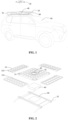
- an exemplary implementation of the present disclosure provides an onboard charging device for an unmanned aerial vehicle (UAV), which includes a platform 10 configured to be mounted on top of a vehicle 50.
- a charging module 30 is configured to charge the unmanned aerial vehicle 20, where the charging module 30 is arranged on the platform 10.
- the platform 10 includes a docking station to dock the UAV
- the charging module 30 may include a charger and related supporting circuit.
- the present disclosure further provides a vehicle, the onboard charging device for the unmanned aerial vehicle being mounted on top of the vehicle.
- the platform 10 in the onboard charging device for the unmanned aerial vehicle provided by the present disclosure may provide a flat landing site for the unmanned aerial vehicle 20, and influence of an external environment is eliminated, so that a blade and the like of the unmanned aerial vehicle 20 may be prevented from being damaged; and on the other hand, the charging module 30 on the platform 10 may charge the unmanned aerial vehicle 20 to guarantee a flight duration for the unmanned aerial vehicle 20 after the unmanned aerial vehicle 20 lands.
- the charging device may further include a power storage module 40 mounted on the platform 10, and the power storage module 40 is electrically connected with the charging module 30, so that the power storage module 40 may fit with the charging module 30 to provide a current output to the unmanned aerial vehicle 20, wherein the power storage module 40 may be, for example, a storage battery.
- the charging module 30 is formed on the platform 10, and an upper surface is flush with the platform 10 to avoid interference and influence on landing of the unmanned aerial vehicle 20.
- the charging module 30 may provide a wired output for the unmanned aerial vehicle in a form of plug connection fit and the like with the unmanned aerial vehicle 20, and may also provide a wireless output for the unmanned aerial vehicle in a wireless charging form.
- the charging module 30 may be a wireless charging module.
- the wireless charging module may perform electric signal interaction with the power storage module 40 firstly and then wirelessly output electric power to a battery of the unmanned aerial vehicle 20.
- the form for wireless charging is well known by those skilled in the art, and will not be elaborated herein.
- the wireless charging module may adopt a form such as an electromagnetic sensing form, a magnetic resonance form or a radio wave form. Under such a condition, when the unmanned aerial vehicle 20 is charged, it is only necessary to make the unmanned aerial vehicle 20 land on the platform 10 and position it within an operation range of the wireless charging module. Such a charging process may complete charging without manual intervention, and is convenient to operate.
- the wireless charging module may include: a receiving unit, configured to receive power information of the unmanned aerial vehicle; a determination unit, configured to determine whether the unmanned aerial vehicle has low power or not; and a charging unit, configured to charge the unmanned aerial vehicle when the unmanned aerial vehicle has low power.
- the charging device provided by the present disclosure may automatically detect that the unmanned aerial vehicle 20 has insufficient power using the receiving module and automatically enter a charging state to recover a flight duration of the unmanned aerial vehicle 20 within a short time; and moreover, after the unmanned aerial vehicle 20 is completely charged, the judgment module determines that the unmanned aerial vehicle 20 has sufficient power, and the charging device may automatically stop the charging process.
- the platform 10 may be a solar panel, and the solar panel is electrically connected with the power storage module 40 to store solar energy in the power storage module 40, thereby timely supplying electric power to the power storage module 40 by virtue of a sufficient solar energy resource.
- a power supply manner is energy-saving and environmentally-friendly.
- the platform 10 includes a bottom plate 11 and side plates 12 pivoted to edges of the bottom plate 11.
- the bottom plate 11 is a tetragon, and there are four side plates 12 pivoted to the four edges of the bottom plate 11 respectively.
- the platform 10 is endowed with an unfolded state and a storage state.
- the side plates 12 are parallel to the bottom plate 11; and in the storage state, the side plates 12 pivot upwards to form a groove structure capable of accommodating the unmanned aerial vehicle.
- the four side plates 12 enclose a closed annular structure in the storage state. There are no specific limits made to specific shapes of the bottom plate 11 and the side plates 12.
- the bottom plate 11 may also be another polygon, irregular pattern and the like, and the side plates 12 may be other corresponding shapes.
- the platform 10 In the unfolded state, the platform 10 may provide a relatively large landing space for the unmanned aerial vehicle 20, and moreover, when the bottom plate 11 and the side plates 12 are solar panels respectively, the solar energy may be maximally collected in such a state.
- the platform 10 accommodates the unmanned aerial vehicle 20 in an enclosing manner, which is convenient and rapid. This may eliminate influence of wind power and the like caused by running of a vehicle on the unmanned aerial vehicle 20 and may also prevent a limited space in the vehicle from being occupied.
- the charging module 30 may be arranged in the center of the bottom plate 11. In such a manner, the unmanned aerial vehicle 20 may be not damaged by overturning of the side plates 12 when landing on the bottom plate 11.
- the bottom plate 11 may further include locking mechanism to lock the UAV in a fixed position while charging.
- the charging device further includes a driving mechanism configured to drive the side plates 12 to pivot relative to the bottom plate 11 to endow the platform with the unfolded state and the storage state.
- the bottom plate 11 is connected with the side plates 12 through rotating shafts
- the driving mechanism may include a motor capable of driving the rotating shafts and a controller for controlling the motor, a wireless signal receiving module being arranged in the controller.
- An operator may control rotation of the rotating shafts to unfold or overturn upwards the side plates 12 by means of operating the controller through a mobile terminal.
- the mobile terminal may be, for example, a remote controller or a smart phone.
- An operating signal is sent to the controller through the remote controller or the smart phone, and after the wireless signal receiving module receives the operating signal, the motor may be controlled to be started, thereby implementing movements of the side plates 12.
- splicing structures may be arranged between every two adjacent side plates 12.
- an inserted block 121 is arranged on an edge of an upper end face of one side plate 12, and a slot 122 is formed in a side end face of the other adjacent side plate 12.
- the inserted block 121 may mate with the slot 122, thereby enabling the annular structure formed by the side plates 12 to be stable.
- positioning sensors 70 configured to guide the unmanned aerial vehicle 20 to land are arranged on the platform 10.
- the positioning sensors 70 are arranged on the bottom plate 11 and are basically positioned in the center of the bottom plate 11 to prevent the unmanned aerial vehicle 20 from being damaged when the side plates 12 are overturned.
- the positioning sensors 70 fits with a sensor on the unmanned aerial vehicle 20 to enable the unmanned aerial vehicle to accurately land on the platform 10.
- the positioning sensors 70 may send infrared or photoelectric signals and the like and fit with an optical flow sensor on the unmanned aerial vehicle 20, and the optical flow sensor may recognize positions of the positioning sensors 70, such that the unmanned aerial vehicle 20 may accurately land on the platform 10.
- the positioning sensors 70 are arranged around the charging module 30, and in such a manner, the unmanned aerial vehicle 20 may land in an area enclosed by the positioning sensors 70, namely positioned above the charging module 30, so that the unmanned aerial vehicle 20 may be conveniently charged by the charging module 30.
- the present disclosure further provides a vehicle 50 including a vehicle top.
- the onboard charging device for the unmanned aerial vehicle may be mounted on the vehicle top.
- the vehicle 50 may serve as a mobile charging device for the unmanned aerial vehicle 20, and may provide a rising and landing platform for the unmanned aerial vehicle 20.
- the vehicle 50 includes top luggage racks 51, and the platform 10 may be detachably mounted on the top luggage racks 51 through a bracket 60, so that overall stability of the charging device and convenience for operation of a user may be ensured.
- the bracket 60 may include a pair of beams crossing the two top luggage racks 51 and a base plate positioned between the two beams, and the platform 10 may be mounted on the base plate in form of clamping, threaded connection or the like.
Landscapes
- Engineering & Computer Science (AREA)
- Power Engineering (AREA)
- Mechanical Engineering (AREA)
- Aviation & Aerospace Engineering (AREA)
- Computer Networks & Wireless Communication (AREA)
- Transportation (AREA)
- Chemical & Material Sciences (AREA)
- Combustion & Propulsion (AREA)
- Remote Sensing (AREA)
- Charge And Discharge Circuits For Batteries Or The Like (AREA)
Claims (12)
- Eine bordeigene bzw.- On-Board- Ladevorrichtung für ein unbemanntes Luftfahrzeug, umfassend:eine Plattform (10), die so konfiguriert ist, dass sie oben auf einem Fahrzeug (50) montiert werden kann und eine Bodenplatte (11) umfasst; undein Lademodul (30), das auf der Plattform (10) angeordnet und zum Aufladen des unbemannten Luftfahrzeugs (20) konfiguriert ist;wobei die Bodenplatte (11) einen Verriegelungsmechanismus umfasst, der so konfiguriert ist, dass er das unbemannte Luftfahrzeug während des Aufladens in einer festen Position verriegelt;dadurch gekennzeichnet, dass die Plattform (10) ferner Seitenplatten (12) umfasst, die an den Kanten der Bodenplatte (11) schwenkbar angebracht sind, wobei die Bodenplatte (11) ein Tetragon ist und die Seitenplatten (12) vier Seitenplatten sind, die jeweils an den vier Kanten der Bodenplatte (11) schwenkbar angebracht sind, wobei die Plattform (10) einen aufgeklappten Zustand und einen Lagerungszustand aufweist, wobei die vier Seitenplatten (12) im Lagerungszustand eine geschlossene ringförmige Struktur einschließen; undwobei Positionierungssensoren (70) um das Lademodul (30) herum auf der Plattform (10) angeordnet sind und so konfiguriert sind, dass sie das unbemannte Luftfahrzeug (20) zur Landung führen, und die Positionierungssensoren (70) auf der Bodenplatte (11) angeordnet und in der Mitte der Bodenplatte (11) positioniert sind .
- Die bordeigene Ladevorrichtung für ein unbemanntes Luftfahrzeug nach Anspruch 1, ferner umfassend ein Energiespeichermodul (40), das auf der Plattform (10) montiert ist, wobei das Energiespeichermodul (40) elektrisch mit dem Lademodul (30) verbunden ist.
- Die bordeigene Ladevorrichtung für ein unbemanntes Luftfahrzeug nach Anspruch 1 oder 2, wobei das Lademodul (3) ein drahtloses Lademodul umfasst.
- Die bordseitige Ladevorrichtung für ein unbemanntes Luftfahrzeug nach Anspruch 3, wobei das drahtlose Lademodul umfasst:eine Empfangseinheit, die so konfiguriert ist, dass sie Leistungsinformationen des unbemannten Luftfahrzeugs empfängt;eine Bestimmungseinheit, die so konfiguriert ist, dass sie feststellt, ob das unbemannte Luftfahrzeug mit niedriger Leistung hat oder nicht; undeine Ladeeinheit, die so konfiguriert ist, dass sie das unbemannte Luftfahrzeug auflädt, wenn das unbemannte Luftfahrzeug eine geringe Leistung hat.
- Die bordeigene Ladevorrichtung für ein unbemanntes Luftfahrzeug nach Anspruch 2, wobei die Plattform (10) ein Solarpanel umfasst und das Solarpanel elektrisch mit dem Energiespeichermodul (40) verbunden ist.
- Die bordeigene Ladevorrichtung für ein unbemanntes Luftfahrzeug nach Anspruch 1 oder 5, , wobei die bordseitige Ladevorrichtung ferner einen Antriebsmechanismus umfasst, der so konfiguriert ist, dass er die Plattform durch Bewegen mindestens einer der Seitenplatten (12) aus dem ausgeklappten Zustand in den Lagerungszustand schaltet.
- Die bordeigene Ladevorrichtung für ein unbemanntes Luftfahrzeug nach Anspruch 1 oder 5, wobei die bordeigene Ladevorrichtung ferner einen Antriebsmechanismus umfasst, der so konfiguriert ist, dass er die Seitenplatten (12) so antreibt, dass sie relativ zur Bodenplatte (11) schwenken, um die Plattform (10) mit dem ausgeklappten Zustand und dem Lagerungszustand auszustatten, wobei die Seitenplatten (12) im ausgeklappten Zustand parallel zur Bodenplatte (11) sind und die Seitenplatten (12) nach oben schwenken, um eine Nutenstruktur zu bilden, die das unbemannte Luftfahrzeug im Lagerungszustand aufnehmen kann.
- Die bordeigene Ladevorrichtung für ein unbemanntes Luftfahrzeug nach Anspruch 7, wobei der Antriebsmechanismus einen Motor und eine Steuerung zur Steuerung des Motors umfasst und in der Steuerung ein drahtloses Signalempfangsmodul angeordnet ist.
- Ein Fahrzeug (50), umfassend:ein Fahrzeugverdeck; unddie bordeigene Ladevorrichtung für ein unbemanntes Luftfahrzeug nach einem der Ansprüche 1-8, die auf dem Fahrzeugdach montiert ist.
- Fahrzeug (50) nach Anspruch 9, das obere Gepäckträger (51) umfasst, wobei die Plattform (10) über eine Halterung (60) abnehmbar an den oberen Gepäckträgern (51) angebracht ist.
- Fahrzeug (50) nach Anspruch 10, wobei das Lademodul (3) ein drahtloses Lademodul umfasst.
- Fahrzeug (50) nach Anspruch 11, wobei das drahtlose Lademodul umfasst:eine Empfangseinheit, die so konfiguriert ist, dass sie Leistungsinformationen des unbemannten Luftfahrzeugs empfängt;eine Bestimmungseinheit, die so konfiguriert ist, dass sie bestimmt, ob das unbemannte Luftfahrzeug eine geringe Leistung hat oder nicht; undeine Ladeeinheit, die so konfiguriert ist, dass sie das unbemannte Luftfahrzeug auflädt, wenn das unbemannte Luftfahrzeug wenig Energie hat.
Applications Claiming Priority (1)
| Application Number | Priority Date | Filing Date | Title |
|---|---|---|---|
| CN201611187863.XA CN106787105A (zh) | 2016-12-20 | 2016-12-20 | 无人机车载充电装置及车辆 |
Publications (2)
| Publication Number | Publication Date |
|---|---|
| EP3340423A1 EP3340423A1 (de) | 2018-06-27 |
| EP3340423B1 true EP3340423B1 (de) | 2024-02-07 |
Family
ID=58894234
Family Applications (1)
| Application Number | Title | Priority Date | Filing Date |
|---|---|---|---|
| EP17208938.5A Active EP3340423B1 (de) | 2016-12-20 | 2017-12-20 | Bordeigene ladevorrichtung für unbemanntes luftfahrzeug und fahrzeug damit |
Country Status (3)
| Country | Link |
|---|---|
| US (1) | US20180170191A1 (de) |
| EP (1) | EP3340423B1 (de) |
| CN (1) | CN106787105A (de) |
Families Citing this family (43)
| Publication number | Priority date | Publication date | Assignee | Title |
|---|---|---|---|---|
| CN108215818B (zh) * | 2016-12-15 | 2020-06-19 | 比亚迪股份有限公司 | 交通工具充电方法和装置 |
| CN107044218A (zh) * | 2017-06-15 | 2017-08-15 | 杭州迪洛智能设备有限公司 | 一种用于无人机自动充电的基站设备 |
| CN107287991A (zh) * | 2017-07-17 | 2017-10-24 | 上海宝冶集团南京建筑有限公司 | 利用bim结合二维码的构件安装方法及无人机及充电座 |
| US10882410B2 (en) * | 2017-07-19 | 2021-01-05 | Wing Aviation Llc | Systems for charging aerial vehicles |
| CN206923855U (zh) * | 2017-07-24 | 2018-01-26 | 深圳市大疆创新科技有限公司 | 无人机的伴飞背包及无人机伴飞系统 |
| CN107685675A (zh) * | 2017-09-21 | 2018-02-13 | 上海合时安防技术有限公司 | 一体化监控排爆机器人航母底盘 |
| US10526094B2 (en) * | 2017-09-29 | 2020-01-07 | Coretronic Intelligent Robotics Corporation | Platform |
| CN107416223A (zh) * | 2017-10-10 | 2017-12-01 | 佛山市领卓科技有限公司 | 一种中继站 |
| CN107628263A (zh) * | 2017-10-10 | 2018-01-26 | 镇江皮埃纳米科技有限公司 | 一种中继站 |
| CN107599875B (zh) * | 2017-10-18 | 2023-10-20 | 武汉博泰电力自动化设备有限责任公司 | 一种车载无人机充电起降平台 |
| CN109153458B (zh) * | 2017-10-31 | 2022-04-26 | 深圳市大疆创新科技有限公司 | 定位机构、无人机基站和无人机系统 |
| CN108008737A (zh) * | 2017-11-29 | 2018-05-08 | 安徽玄同工业设计有限公司 | 一种车载无人机的施放及回收装置 |
| KR102314928B1 (ko) * | 2017-12-07 | 2021-10-20 | 현대모비스 주식회사 | 무인기 착륙 장치 |
| CN108082518A (zh) * | 2018-01-29 | 2018-05-29 | 成都市煜沣科技有限公司 | 一种适用于物流无人机中转充电装置 |
| CN108082519A (zh) * | 2018-01-29 | 2018-05-29 | 成都市煜沣科技有限公司 | 一种适用于小型无人机降落定位充电平台 |
| CN108422884B (zh) * | 2018-03-30 | 2020-10-13 | 榛硕(武汉)智能科技有限公司 | 基于无人机的电动汽车电能补充系统 |
| US11787346B2 (en) * | 2018-04-20 | 2023-10-17 | Axon Enterprise, Inc. | Systems and methods for a housing equipment for a security vehicle |
| CN109466788A (zh) * | 2018-05-14 | 2019-03-15 | 国网浙江省电力有限公司嘉兴供电公司 | 一种无人机地面站操作平台 |
| US11891192B2 (en) * | 2018-07-23 | 2024-02-06 | Shanghai Autoflight Co., Ltd. | Landing platform for unmanned aerial vehicle |
| GB201812065D0 (en) | 2018-07-24 | 2018-09-05 | Lodestar Systems Ltd | Drone recharging station |
| CN109455308A (zh) * | 2018-12-27 | 2019-03-12 | 祺步智能科技(上海)有限公司 | 一种无人机停机库及运输工具 |
| CN109850173B (zh) * | 2019-03-14 | 2020-11-24 | 燕山大学 | 基于六自由度并联调姿机构的多功能车载模式平台装置 |
| US11572197B1 (en) * | 2019-03-15 | 2023-02-07 | Alarm.Com Incorporated | Stations for unmanned aerial vehicles |
| TR201906925A2 (tr) * | 2019-05-09 | 2020-11-23 | Aselsan Elektronik Sanayi Ve Ticaret As | İnsansiz hava araçlari i̇çi̇n elektri̇k tahri̇kli̇ mobi̇l güç ve yer platformu |
| CN110068524B (zh) * | 2019-06-03 | 2024-07-02 | 南京信息工程大学 | 大气颗粒物含铅及其同位素检测系统 |
| CN110341975A (zh) * | 2019-07-22 | 2019-10-18 | 金陵科技学院 | 一种含无人机的太阳能配运站 |
| US11767110B2 (en) * | 2019-12-16 | 2023-09-26 | FLIR Unmanned Aerial Systems AS | System for storing, autonomously launching and landing unmanned aerial vehicles |
| KR20210153773A (ko) * | 2020-06-09 | 2021-12-20 | 현대자동차주식회사 | 드론과 차량간의 배송시스템 및 그 제어방법 |
| CN114435614A (zh) * | 2020-11-05 | 2022-05-06 | 北星空间信息技术研究院(南京)有限公司 | 一种无人机动态降落地面机器人的方法 |
| CN112520057A (zh) * | 2020-12-09 | 2021-03-19 | 中国建筑土木建设有限公司 | 一种多功能多旋翼无人机收纳箱 |
| CN113232576B (zh) * | 2021-05-19 | 2022-08-05 | 南京航空航天大学 | 一种可拼接的二段折叠车载展开平台及操作方法 |
| CN215476898U (zh) * | 2021-06-07 | 2022-01-11 | 上海峰飞航空科技有限公司 | 一种无人机运输箱 |
| CN113277080B (zh) * | 2021-06-20 | 2023-07-14 | 上海倬彼云汉航空科技有限公司 | 一种用于无人机充电的扑翼平台及其充电方法 |
| KR102583405B1 (ko) * | 2021-07-05 | 2023-09-27 | 주식회사 아르고스다인 | 드론 스테이션 |
| CN113928560B (zh) * | 2021-10-21 | 2024-02-27 | 中煤航测遥感集团有限公司 | 一种航空摄影测量用无人机平台及摄影方法 |
| CN114180090B (zh) * | 2021-12-11 | 2024-02-02 | 浙江极客桥智能装备股份有限公司 | 一种无人机智能存放管理方法及系统 |
| JP2024035645A (ja) * | 2022-09-02 | 2024-03-14 | 舘林 秋宣 | ドローン収納ボックス |
| CN115924159B (zh) * | 2023-03-10 | 2023-05-16 | 四川省天域航通科技有限公司 | 大型无人机智能指挥控制平台及其控制方法 |
| US12316272B2 (en) | 2023-04-07 | 2025-05-27 | Nicholas J. Singer | Solar panel pillar |
| US11999266B1 (en) * | 2023-04-07 | 2024-06-04 | Nicholas J. Singer | Solar platform |
| US12047035B1 (en) | 2023-04-07 | 2024-07-23 | Nicholas J. Singer | Solar 3D platform |
| US12565345B1 (en) | 2023-05-28 | 2026-03-03 | Antonio Liska | Automated drone storage and launch apparatus, system, and method |
| CN117048881B (zh) * | 2023-10-12 | 2024-01-02 | 成都航空职业技术学院 | 一种空中充电无人机组及其充电方法 |
Family Cites Families (13)
| Publication number | Priority date | Publication date | Assignee | Title |
|---|---|---|---|---|
| US8511606B1 (en) * | 2009-12-09 | 2013-08-20 | The Boeing Company | Unmanned aerial vehicle base station |
| CN103208832B (zh) * | 2013-03-14 | 2014-12-17 | 深圳市中远航科技有限公司 | 一种太阳能无线充电电源 |
| WO2015195175A2 (en) * | 2014-03-21 | 2015-12-23 | Borko Brandon | System for automatic takeoff and landing by interception of small uavs |
| US9561871B2 (en) * | 2014-05-07 | 2017-02-07 | Deere & Company | UAV docking system and method |
| CN205345354U (zh) * | 2014-11-28 | 2016-06-29 | 湖北智权知识产权咨询有限公司 | 无人飞行器智能维护平台及其农林水产应用系统 |
| US9915956B2 (en) * | 2015-01-09 | 2018-03-13 | Workhorse Group Inc. | Package delivery by means of an automated multi-copter UAS/UAV dispatched from a conventional delivery vehicle |
| CN108137153B (zh) * | 2015-01-18 | 2022-07-15 | 基础制造有限公司 | 用于无人机的装置、系统和方法 |
| US9540121B2 (en) * | 2015-02-25 | 2017-01-10 | Cisco Technology, Inc. | Pre-flight self test for unmanned aerial vehicles (UAVs) |
| US9834151B2 (en) * | 2015-03-26 | 2017-12-05 | Dsh Designs, Llc | Vehicle mounted securing system |
| CN205178593U (zh) * | 2015-12-09 | 2016-04-20 | 长沙钛合电子设备有限公司 | 无人机充电平台 |
| CN205750548U (zh) * | 2016-05-09 | 2016-11-30 | 北京中科精图信息技术有限公司 | 一种基于无人机的巡查系统 |
| CN106004626A (zh) * | 2016-06-14 | 2016-10-12 | 郭永 | 一种无人机车载多功能平台 |
| CN206790194U (zh) * | 2016-12-20 | 2017-12-22 | 北京小米移动软件有限公司 | 无人机车载充电装置及车辆 |
-
2016
- 2016-12-20 CN CN201611187863.XA patent/CN106787105A/zh active Pending
-
2017
- 2017-12-20 EP EP17208938.5A patent/EP3340423B1/de active Active
- 2017-12-20 US US15/849,111 patent/US20180170191A1/en not_active Abandoned
Also Published As
| Publication number | Publication date |
|---|---|
| EP3340423A1 (de) | 2018-06-27 |
| CN106787105A (zh) | 2017-05-31 |
| US20180170191A1 (en) | 2018-06-21 |
Similar Documents
| Publication | Publication Date | Title |
|---|---|---|
| EP3340423B1 (de) | Bordeigene ladevorrichtung für unbemanntes luftfahrzeug und fahrzeug damit | |
| US11643205B2 (en) | Systems and methods for charging, transporting, and operating flying machines | |
| US9623760B2 (en) | System and method for managing unmanned aerial vehicles | |
| EP4087754B1 (de) | Autonome basisstation und netzwerk für unbemannte fahrzeuge | |
| JP6395835B2 (ja) | Uavのバッテリー電源バックアップシステムおよび方法 | |
| US20190100108A1 (en) | Robotic Vehicle Renewable Resource Charging Station Management Systems and Methods | |
| CN111056032B (zh) | 一种无人船载的无人机充电升降系统及实现方法 | |
| KR20190125130A (ko) | 차량에서 자동으로 이륙과 착륙 및 충전하도록 구성된 드론 도킹 스테이션 차량 | |
| JP2018100088A (ja) | Uavにエネルギーを供給する方法、及びuav | |
| CN205469865U (zh) | 带自动充电装置的无人值守的无人机起降平台及系统 | |
| EP4139763B1 (de) | Verfahren und system zur bestimmung der position eines drohnenkastens für stabilisierte landung und vergebührung einer drohne | |
| KR102111055B1 (ko) | 드론용 무선충전 스테이션 | |
| CN106655322A (zh) | 服务型无人机、无人机充电系统及充电方法 | |
| CN107390717A (zh) | 用于输变电站巡检的巡检无人机及系统 | |
| JP2018192932A (ja) | 無人飛行体およびその格納システム | |
| CN206790194U (zh) | 无人机车载充电装置及车辆 | |
| JP2019172255A (ja) | Uavにエネルギーを供給する方法、及び装置 | |
| CN110254737A (zh) | 一种多功能无人机综合管理平台及其控制方法 | |
| KR20170049840A (ko) | 무인 비행기의 옥외용 격납 장치 | |
| RU185019U1 (ru) | Базовая станция с функцией зарядки батареи беспилотного летательного аппарата | |
| KR20230069284A (ko) | 태양광 기반 드론 충전스테이션 | |
| CN205221113U (zh) | 腕式便携伴飞自主监控无人机 | |
| CN105958627A (zh) | 一种船载无人机电源系统 | |
| HK40002254A (en) | Systems and methods for charging, transporting, and operating flying machines | |
| HK40002254B (en) | Systems and methods for charging, transporting, and operating flying machines |
Legal Events
| Date | Code | Title | Description |
|---|---|---|---|
| PUAI | Public reference made under article 153(3) epc to a published international application that has entered the european phase |
Free format text: ORIGINAL CODE: 0009012 |
|
| STAA | Information on the status of an ep patent application or granted ep patent |
Free format text: STATUS: REQUEST FOR EXAMINATION WAS MADE |
|
| 17P | Request for examination filed |
Effective date: 20171220 |
|
| AK | Designated contracting states |
Kind code of ref document: A1 Designated state(s): AL AT BE BG CH CY CZ DE DK EE ES FI FR GB GR HR HU IE IS IT LI LT LU LV MC MK MT NL NO PL PT RO RS SE SI SK SM TR |
|
| AX | Request for extension of the european patent |
Extension state: BA ME |
|
| RBV | Designated contracting states (corrected) |
Designated state(s): AL AT BE BG CH CY CZ DE DK EE ES FI FR GB GR HR HU IE IS IT LI LT LU LV MC MK MT NL NO PL PT RO RS SE SI SK SM TR |
|
| STAA | Information on the status of an ep patent application or granted ep patent |
Free format text: STATUS: EXAMINATION IS IN PROGRESS |
|
| 17Q | First examination report despatched |
Effective date: 20210622 |
|
| RIC1 | Information provided on ipc code assigned before grant |
Ipc: H02J 7/35 20060101ALN20230630BHEP Ipc: H02J 7/34 20060101ALN20230630BHEP Ipc: B64F 1/00 20060101ALI20230630BHEP Ipc: B64U 80/86 20230101ALI20230630BHEP Ipc: B60L 53/53 20190101ALI20230630BHEP Ipc: B60L 53/00 20190101ALI20230630BHEP Ipc: H02J 50/10 20160101ALI20230630BHEP Ipc: H02J 7/02 20160101ALI20230630BHEP Ipc: B64C 39/02 20060101ALI20230630BHEP Ipc: H02J 7/00 20060101AFI20230630BHEP |
|
| RIC1 | Information provided on ipc code assigned before grant |
Ipc: H02J 7/35 20060101ALN20230725BHEP Ipc: H02J 7/34 20060101ALN20230725BHEP Ipc: B64F 1/00 20060101ALI20230725BHEP Ipc: B64U 80/86 20230101ALI20230725BHEP Ipc: B60L 53/53 20190101ALI20230725BHEP Ipc: B60L 53/00 20190101ALI20230725BHEP Ipc: H02J 50/10 20160101ALI20230725BHEP Ipc: H02J 7/02 20160101ALI20230725BHEP Ipc: B64C 39/02 20060101ALI20230725BHEP Ipc: H02J 7/00 20060101AFI20230725BHEP |
|
| GRAP | Despatch of communication of intention to grant a patent |
Free format text: ORIGINAL CODE: EPIDOSNIGR1 |
|
| STAA | Information on the status of an ep patent application or granted ep patent |
Free format text: STATUS: GRANT OF PATENT IS INTENDED |
|
| INTG | Intention to grant announced |
Effective date: 20230901 |
|
| P01 | Opt-out of the competence of the unified patent court (upc) registered |
Effective date: 20230925 |
|
| GRAS | Grant fee paid |
Free format text: ORIGINAL CODE: EPIDOSNIGR3 |
|
| GRAA | (expected) grant |
Free format text: ORIGINAL CODE: 0009210 |
|
| STAA | Information on the status of an ep patent application or granted ep patent |
Free format text: STATUS: THE PATENT HAS BEEN GRANTED |
|
| AK | Designated contracting states |
Kind code of ref document: B1 Designated state(s): AL AT BE BG CH CY CZ DE DK EE ES FI FR GB GR HR HU IE IS IT LI LT LU LV MC MK MT NL NO PL PT RO RS SE SI SK SM TR |
|
| REG | Reference to a national code |
Ref country code: GB Ref legal event code: FG4D |
|
| REG | Reference to a national code |
Ref country code: CH Ref legal event code: EP |
|
| REG | Reference to a national code |
Ref country code: IE Ref legal event code: FG4D |
|
| REG | Reference to a national code |
Ref country code: DE Ref legal event code: R096 Ref document number: 602017078968 Country of ref document: DE |
|
| REG | Reference to a national code |
Ref country code: LT Ref legal event code: MG9D |
|
| REG | Reference to a national code |
Ref country code: NL Ref legal event code: MP Effective date: 20240207 |
|
| PG25 | Lapsed in a contracting state [announced via postgrant information from national office to epo] |
Ref country code: IS Free format text: LAPSE BECAUSE OF FAILURE TO SUBMIT A TRANSLATION OF THE DESCRIPTION OR TO PAY THE FEE WITHIN THE PRESCRIBED TIME-LIMIT Effective date: 20240607 |
|
| PG25 | Lapsed in a contracting state [announced via postgrant information from national office to epo] |
Ref country code: LT Free format text: LAPSE BECAUSE OF FAILURE TO SUBMIT A TRANSLATION OF THE DESCRIPTION OR TO PAY THE FEE WITHIN THE PRESCRIBED TIME-LIMIT Effective date: 20240207 |
|
| PG25 | Lapsed in a contracting state [announced via postgrant information from national office to epo] |
Ref country code: GR Free format text: LAPSE BECAUSE OF FAILURE TO SUBMIT A TRANSLATION OF THE DESCRIPTION OR TO PAY THE FEE WITHIN THE PRESCRIBED TIME-LIMIT Effective date: 20240508 |
|
| REG | Reference to a national code |
Ref country code: AT Ref legal event code: MK05 Ref document number: 1655995 Country of ref document: AT Kind code of ref document: T Effective date: 20240207 |
|
| PG25 | Lapsed in a contracting state [announced via postgrant information from national office to epo] |
Ref country code: RS Free format text: LAPSE BECAUSE OF FAILURE TO SUBMIT A TRANSLATION OF THE DESCRIPTION OR TO PAY THE FEE WITHIN THE PRESCRIBED TIME-LIMIT Effective date: 20240507 Ref country code: NL Free format text: LAPSE BECAUSE OF FAILURE TO SUBMIT A TRANSLATION OF THE DESCRIPTION OR TO PAY THE FEE WITHIN THE PRESCRIBED TIME-LIMIT Effective date: 20240207 Ref country code: HR Free format text: LAPSE BECAUSE OF FAILURE TO SUBMIT A TRANSLATION OF THE DESCRIPTION OR TO PAY THE FEE WITHIN THE PRESCRIBED TIME-LIMIT Effective date: 20240207 |
|
| PG25 | Lapsed in a contracting state [announced via postgrant information from national office to epo] |
Ref country code: ES Free format text: LAPSE BECAUSE OF FAILURE TO SUBMIT A TRANSLATION OF THE DESCRIPTION OR TO PAY THE FEE WITHIN THE PRESCRIBED TIME-LIMIT Effective date: 20240207 |
|
| PG25 | Lapsed in a contracting state [announced via postgrant information from national office to epo] |
Ref country code: AT Free format text: LAPSE BECAUSE OF FAILURE TO SUBMIT A TRANSLATION OF THE DESCRIPTION OR TO PAY THE FEE WITHIN THE PRESCRIBED TIME-LIMIT Effective date: 20240207 |
|
| PG25 | Lapsed in a contracting state [announced via postgrant information from national office to epo] |
Ref country code: RS Free format text: LAPSE BECAUSE OF FAILURE TO SUBMIT A TRANSLATION OF THE DESCRIPTION OR TO PAY THE FEE WITHIN THE PRESCRIBED TIME-LIMIT Effective date: 20240507 Ref country code: NO Free format text: LAPSE BECAUSE OF FAILURE TO SUBMIT A TRANSLATION OF THE DESCRIPTION OR TO PAY THE FEE WITHIN THE PRESCRIBED TIME-LIMIT Effective date: 20240507 Ref country code: NL Free format text: LAPSE BECAUSE OF FAILURE TO SUBMIT A TRANSLATION OF THE DESCRIPTION OR TO PAY THE FEE WITHIN THE PRESCRIBED TIME-LIMIT Effective date: 20240207 Ref country code: LT Free format text: LAPSE BECAUSE OF FAILURE TO SUBMIT A TRANSLATION OF THE DESCRIPTION OR TO PAY THE FEE WITHIN THE PRESCRIBED TIME-LIMIT Effective date: 20240207 Ref country code: IS Free format text: LAPSE BECAUSE OF FAILURE TO SUBMIT A TRANSLATION OF THE DESCRIPTION OR TO PAY THE FEE WITHIN THE PRESCRIBED TIME-LIMIT Effective date: 20240607 Ref country code: HR Free format text: LAPSE BECAUSE OF FAILURE TO SUBMIT A TRANSLATION OF THE DESCRIPTION OR TO PAY THE FEE WITHIN THE PRESCRIBED TIME-LIMIT Effective date: 20240207 Ref country code: GR Free format text: LAPSE BECAUSE OF FAILURE TO SUBMIT A TRANSLATION OF THE DESCRIPTION OR TO PAY THE FEE WITHIN THE PRESCRIBED TIME-LIMIT Effective date: 20240508 Ref country code: FI Free format text: LAPSE BECAUSE OF FAILURE TO SUBMIT A TRANSLATION OF THE DESCRIPTION OR TO PAY THE FEE WITHIN THE PRESCRIBED TIME-LIMIT Effective date: 20240207 Ref country code: ES Free format text: LAPSE BECAUSE OF FAILURE TO SUBMIT A TRANSLATION OF THE DESCRIPTION OR TO PAY THE FEE WITHIN THE PRESCRIBED TIME-LIMIT Effective date: 20240207 Ref country code: BG Free format text: LAPSE BECAUSE OF FAILURE TO SUBMIT A TRANSLATION OF THE DESCRIPTION OR TO PAY THE FEE WITHIN THE PRESCRIBED TIME-LIMIT Effective date: 20240207 Ref country code: AT Free format text: LAPSE BECAUSE OF FAILURE TO SUBMIT A TRANSLATION OF THE DESCRIPTION OR TO PAY THE FEE WITHIN THE PRESCRIBED TIME-LIMIT Effective date: 20240207 |
|
| PG25 | Lapsed in a contracting state [announced via postgrant information from national office to epo] |
Ref country code: PT Free format text: LAPSE BECAUSE OF FAILURE TO SUBMIT A TRANSLATION OF THE DESCRIPTION OR TO PAY THE FEE WITHIN THE PRESCRIBED TIME-LIMIT Effective date: 20240607 Ref country code: PL Free format text: LAPSE BECAUSE OF FAILURE TO SUBMIT A TRANSLATION OF THE DESCRIPTION OR TO PAY THE FEE WITHIN THE PRESCRIBED TIME-LIMIT Effective date: 20240207 |
|
| PG25 | Lapsed in a contracting state [announced via postgrant information from national office to epo] |
Ref country code: SE Free format text: LAPSE BECAUSE OF FAILURE TO SUBMIT A TRANSLATION OF THE DESCRIPTION OR TO PAY THE FEE WITHIN THE PRESCRIBED TIME-LIMIT Effective date: 20240207 Ref country code: PT Free format text: LAPSE BECAUSE OF FAILURE TO SUBMIT A TRANSLATION OF THE DESCRIPTION OR TO PAY THE FEE WITHIN THE PRESCRIBED TIME-LIMIT Effective date: 20240607 Ref country code: PL Free format text: LAPSE BECAUSE OF FAILURE TO SUBMIT A TRANSLATION OF THE DESCRIPTION OR TO PAY THE FEE WITHIN THE PRESCRIBED TIME-LIMIT Effective date: 20240207 Ref country code: LV Free format text: LAPSE BECAUSE OF FAILURE TO SUBMIT A TRANSLATION OF THE DESCRIPTION OR TO PAY THE FEE WITHIN THE PRESCRIBED TIME-LIMIT Effective date: 20240207 |
|
| PG25 | Lapsed in a contracting state [announced via postgrant information from national office to epo] |
Ref country code: DK Free format text: LAPSE BECAUSE OF FAILURE TO SUBMIT A TRANSLATION OF THE DESCRIPTION OR TO PAY THE FEE WITHIN THE PRESCRIBED TIME-LIMIT Effective date: 20240207 |
|
| PG25 | Lapsed in a contracting state [announced via postgrant information from national office to epo] |
Ref country code: SM Free format text: LAPSE BECAUSE OF FAILURE TO SUBMIT A TRANSLATION OF THE DESCRIPTION OR TO PAY THE FEE WITHIN THE PRESCRIBED TIME-LIMIT Effective date: 20240207 |
|
| PG25 | Lapsed in a contracting state [announced via postgrant information from national office to epo] |
Ref country code: CZ Free format text: LAPSE BECAUSE OF FAILURE TO SUBMIT A TRANSLATION OF THE DESCRIPTION OR TO PAY THE FEE WITHIN THE PRESCRIBED TIME-LIMIT Effective date: 20240207 Ref country code: EE Free format text: LAPSE BECAUSE OF FAILURE TO SUBMIT A TRANSLATION OF THE DESCRIPTION OR TO PAY THE FEE WITHIN THE PRESCRIBED TIME-LIMIT Effective date: 20240207 |
|
| PG25 | Lapsed in a contracting state [announced via postgrant information from national office to epo] |
Ref country code: SK Free format text: LAPSE BECAUSE OF FAILURE TO SUBMIT A TRANSLATION OF THE DESCRIPTION OR TO PAY THE FEE WITHIN THE PRESCRIBED TIME-LIMIT Effective date: 20240207 |
|
| PG25 | Lapsed in a contracting state [announced via postgrant information from national office to epo] |
Ref country code: SM Free format text: LAPSE BECAUSE OF FAILURE TO SUBMIT A TRANSLATION OF THE DESCRIPTION OR TO PAY THE FEE WITHIN THE PRESCRIBED TIME-LIMIT Effective date: 20240207 Ref country code: SK Free format text: LAPSE BECAUSE OF FAILURE TO SUBMIT A TRANSLATION OF THE DESCRIPTION OR TO PAY THE FEE WITHIN THE PRESCRIBED TIME-LIMIT Effective date: 20240207 Ref country code: RO Free format text: LAPSE BECAUSE OF FAILURE TO SUBMIT A TRANSLATION OF THE DESCRIPTION OR TO PAY THE FEE WITHIN THE PRESCRIBED TIME-LIMIT Effective date: 20240207 Ref country code: EE Free format text: LAPSE BECAUSE OF FAILURE TO SUBMIT A TRANSLATION OF THE DESCRIPTION OR TO PAY THE FEE WITHIN THE PRESCRIBED TIME-LIMIT Effective date: 20240207 Ref country code: DK Free format text: LAPSE BECAUSE OF FAILURE TO SUBMIT A TRANSLATION OF THE DESCRIPTION OR TO PAY THE FEE WITHIN THE PRESCRIBED TIME-LIMIT Effective date: 20240207 Ref country code: CZ Free format text: LAPSE BECAUSE OF FAILURE TO SUBMIT A TRANSLATION OF THE DESCRIPTION OR TO PAY THE FEE WITHIN THE PRESCRIBED TIME-LIMIT Effective date: 20240207 |
|
| REG | Reference to a national code |
Ref country code: DE Ref legal event code: R097 Ref document number: 602017078968 Country of ref document: DE |
|
| PG25 | Lapsed in a contracting state [announced via postgrant information from national office to epo] |
Ref country code: IT Free format text: LAPSE BECAUSE OF FAILURE TO SUBMIT A TRANSLATION OF THE DESCRIPTION OR TO PAY THE FEE WITHIN THE PRESCRIBED TIME-LIMIT Effective date: 20240207 |
|
| PLBE | No opposition filed within time limit |
Free format text: ORIGINAL CODE: 0009261 |
|
| STAA | Information on the status of an ep patent application or granted ep patent |
Free format text: STATUS: NO OPPOSITION FILED WITHIN TIME LIMIT |
|
| PG25 | Lapsed in a contracting state [announced via postgrant information from national office to epo] |
Ref country code: IT Free format text: LAPSE BECAUSE OF FAILURE TO SUBMIT A TRANSLATION OF THE DESCRIPTION OR TO PAY THE FEE WITHIN THE PRESCRIBED TIME-LIMIT Effective date: 20240207 |
|
| 26N | No opposition filed |
Effective date: 20241108 |
|
| PG25 | Lapsed in a contracting state [announced via postgrant information from national office to epo] |
Ref country code: SI Free format text: LAPSE BECAUSE OF FAILURE TO SUBMIT A TRANSLATION OF THE DESCRIPTION OR TO PAY THE FEE WITHIN THE PRESCRIBED TIME-LIMIT Effective date: 20240207 |
|
| PG25 | Lapsed in a contracting state [announced via postgrant information from national office to epo] |
Ref country code: MC Free format text: LAPSE BECAUSE OF FAILURE TO SUBMIT A TRANSLATION OF THE DESCRIPTION OR TO PAY THE FEE WITHIN THE PRESCRIBED TIME-LIMIT Effective date: 20240207 |
|
| REG | Reference to a national code |
Ref country code: CH Ref legal event code: PL |
|
| PG25 | Lapsed in a contracting state [announced via postgrant information from national office to epo] |
Ref country code: LU Free format text: LAPSE BECAUSE OF NON-PAYMENT OF DUE FEES Effective date: 20241220 |
|
| REG | Reference to a national code |
Ref country code: BE Ref legal event code: MM Effective date: 20241231 |
|
| PG25 | Lapsed in a contracting state [announced via postgrant information from national office to epo] |
Ref country code: BE Free format text: LAPSE BECAUSE OF NON-PAYMENT OF DUE FEES Effective date: 20241231 |
|
| PG25 | Lapsed in a contracting state [announced via postgrant information from national office to epo] |
Ref country code: CH Free format text: LAPSE BECAUSE OF NON-PAYMENT OF DUE FEES Effective date: 20241231 |
|
| PG25 | Lapsed in a contracting state [announced via postgrant information from national office to epo] |
Ref country code: IE Free format text: LAPSE BECAUSE OF NON-PAYMENT OF DUE FEES Effective date: 20241220 |
|
| PGFP | Annual fee paid to national office [announced via postgrant information from national office to epo] |
Ref country code: DE Payment date: 20251126 Year of fee payment: 9 |
|
| PGFP | Annual fee paid to national office [announced via postgrant information from national office to epo] |
Ref country code: GB Payment date: 20251120 Year of fee payment: 9 |
|
| PGFP | Annual fee paid to national office [announced via postgrant information from national office to epo] |
Ref country code: FR Payment date: 20251124 Year of fee payment: 9 |