EP3340334B1 - Dichtungsvorrichtung für batteriegehäuse mit erhöhtem druck- und wärmeanwendungsbereich - Google Patents
Dichtungsvorrichtung für batteriegehäuse mit erhöhtem druck- und wärmeanwendungsbereich Download PDFInfo
- Publication number
- EP3340334B1 EP3340334B1 EP16876040.3A EP16876040A EP3340334B1 EP 3340334 B1 EP3340334 B1 EP 3340334B1 EP 16876040 A EP16876040 A EP 16876040A EP 3340334 B1 EP3340334 B1 EP 3340334B1
- Authority
- EP
- European Patent Office
- Prior art keywords
- sealing
- block
- planned part
- planned
- electrode lead
- Prior art date
- Legal status (The legal status is an assumption and is not a legal conclusion. Google has not performed a legal analysis and makes no representation as to the accuracy of the status listed.)
- Active
Links
Images


Classifications
-
- H—ELECTRICITY
- H01—ELECTRIC ELEMENTS
- H01M—PROCESSES OR MEANS, e.g. BATTERIES, FOR THE DIRECT CONVERSION OF CHEMICAL ENERGY INTO ELECTRICAL ENERGY
- H01M10/00—Secondary cells; Manufacture thereof
- H01M10/04—Construction or manufacture in general
- H01M10/0404—Machines for assembling batteries
-
- B—PERFORMING OPERATIONS; TRANSPORTING
- B29—WORKING OF PLASTICS; WORKING OF SUBSTANCES IN A PLASTIC STATE IN GENERAL
- B29C—SHAPING OR JOINING OF PLASTICS; SHAPING OF MATERIAL IN A PLASTIC STATE, NOT OTHERWISE PROVIDED FOR; AFTER-TREATMENT OF THE SHAPED PRODUCTS, e.g. REPAIRING
- B29C65/00—Joining or sealing of preformed parts, e.g. welding of plastics materials; Apparatus therefor
- B29C65/02—Joining or sealing of preformed parts, e.g. welding of plastics materials; Apparatus therefor by heating, with or without pressure
- B29C65/18—Joining or sealing of preformed parts, e.g. welding of plastics materials; Apparatus therefor by heating, with or without pressure using heated tools
-
- B—PERFORMING OPERATIONS; TRANSPORTING
- B29—WORKING OF PLASTICS; WORKING OF SUBSTANCES IN A PLASTIC STATE IN GENERAL
- B29C—SHAPING OR JOINING OF PLASTICS; SHAPING OF MATERIAL IN A PLASTIC STATE, NOT OTHERWISE PROVIDED FOR; AFTER-TREATMENT OF THE SHAPED PRODUCTS, e.g. REPAIRING
- B29C66/00—General aspects of processes or apparatus for joining preformed parts
- B29C66/01—General aspects dealing with the joint area or with the area to be joined
- B29C66/05—Particular design of joint configurations
- B29C66/10—Particular design of joint configurations particular design of the joint cross-sections
- B29C66/11—Joint cross-sections comprising a single joint-segment, i.e. one of the parts to be joined comprising a single joint-segment in the joint cross-section
- B29C66/112—Single lapped joints
- B29C66/1122—Single lap to lap joints, i.e. overlap joints
-
- B—PERFORMING OPERATIONS; TRANSPORTING
- B29—WORKING OF PLASTICS; WORKING OF SUBSTANCES IN A PLASTIC STATE IN GENERAL
- B29C—SHAPING OR JOINING OF PLASTICS; SHAPING OF MATERIAL IN A PLASTIC STATE, NOT OTHERWISE PROVIDED FOR; AFTER-TREATMENT OF THE SHAPED PRODUCTS, e.g. REPAIRING
- B29C66/00—General aspects of processes or apparatus for joining preformed parts
- B29C66/40—General aspects of joining substantially flat articles, e.g. plates, sheets or web-like materials; Making flat seams in tubular or hollow articles; Joining single elements to substantially flat surfaces
- B29C66/41—Joining substantially flat articles ; Making flat seams in tubular or hollow articles
- B29C66/43—Joining a relatively small portion of the surface of said articles
- B29C66/433—Casing-in, i.e. enclosing an element between two sheets by an outlined seam
-
- B—PERFORMING OPERATIONS; TRANSPORTING
- B29—WORKING OF PLASTICS; WORKING OF SUBSTANCES IN A PLASTIC STATE IN GENERAL
- B29C—SHAPING OR JOINING OF PLASTICS; SHAPING OF MATERIAL IN A PLASTIC STATE, NOT OTHERWISE PROVIDED FOR; AFTER-TREATMENT OF THE SHAPED PRODUCTS, e.g. REPAIRING
- B29C66/00—General aspects of processes or apparatus for joining preformed parts
- B29C66/80—General aspects of machine operations or constructions and parts thereof
- B29C66/81—General aspects of the pressing elements, i.e. the elements applying pressure on the parts to be joined in the area to be joined, e.g. the welding jaws or clamps
- B29C66/814—General aspects of the pressing elements, i.e. the elements applying pressure on the parts to be joined in the area to be joined, e.g. the welding jaws or clamps characterised by the design of the pressing elements, e.g. of the welding jaws or clamps
- B29C66/8141—General aspects of the pressing elements, i.e. the elements applying pressure on the parts to be joined in the area to be joined, e.g. the welding jaws or clamps characterised by the design of the pressing elements, e.g. of the welding jaws or clamps characterised by the surface geometry of the part of the pressing elements, e.g. welding jaws or clamps, coming into contact with the parts to be joined
- B29C66/81431—General aspects of the pressing elements, i.e. the elements applying pressure on the parts to be joined in the area to be joined, e.g. the welding jaws or clamps characterised by the design of the pressing elements, e.g. of the welding jaws or clamps characterised by the surface geometry of the part of the pressing elements, e.g. welding jaws or clamps, coming into contact with the parts to be joined comprising a single cavity, e.g. a groove
-
- B—PERFORMING OPERATIONS; TRANSPORTING
- B29—WORKING OF PLASTICS; WORKING OF SUBSTANCES IN A PLASTIC STATE IN GENERAL
- B29C—SHAPING OR JOINING OF PLASTICS; SHAPING OF MATERIAL IN A PLASTIC STATE, NOT OTHERWISE PROVIDED FOR; AFTER-TREATMENT OF THE SHAPED PRODUCTS, e.g. REPAIRING
- B29C66/00—General aspects of processes or apparatus for joining preformed parts
- B29C66/80—General aspects of machine operations or constructions and parts thereof
- B29C66/83—General aspects of machine operations or constructions and parts thereof characterised by the movement of the joining or pressing tools
- B29C66/832—Reciprocating joining or pressing tools
- B29C66/8322—Joining or pressing tools reciprocating along one axis
- B29C66/83221—Joining or pressing tools reciprocating along one axis cooperating reciprocating tools, each tool reciprocating along one axis
-
- H—ELECTRICITY
- H01—ELECTRIC ELEMENTS
- H01M—PROCESSES OR MEANS, e.g. BATTERIES, FOR THE DIRECT CONVERSION OF CHEMICAL ENERGY INTO ELECTRICAL ENERGY
- H01M10/00—Secondary cells; Manufacture thereof
- H01M10/05—Accumulators with non-aqueous electrolyte
- H01M10/052—Li-accumulators
- H01M10/0525—Rocking-chair batteries, i.e. batteries with lithium insertion or intercalation in both electrodes; Lithium-ion batteries
-
- H—ELECTRICITY
- H01—ELECTRIC ELEMENTS
- H01M—PROCESSES OR MEANS, e.g. BATTERIES, FOR THE DIRECT CONVERSION OF CHEMICAL ENERGY INTO ELECTRICAL ENERGY
- H01M50/00—Constructional details or processes of manufacture of the non-active parts of electrochemical cells other than fuel cells, e.g. hybrid cells
- H01M50/10—Primary casings; Jackets or wrappings
- H01M50/116—Primary casings; Jackets or wrappings characterised by the material
- H01M50/124—Primary casings; Jackets or wrappings characterised by the material having a layered structure
-
- H—ELECTRICITY
- H01—ELECTRIC ELEMENTS
- H01M—PROCESSES OR MEANS, e.g. BATTERIES, FOR THE DIRECT CONVERSION OF CHEMICAL ENERGY INTO ELECTRICAL ENERGY
- H01M50/00—Constructional details or processes of manufacture of the non-active parts of electrochemical cells other than fuel cells, e.g. hybrid cells
- H01M50/10—Primary casings; Jackets or wrappings
- H01M50/172—Arrangements of electric connectors penetrating the casing
- H01M50/174—Arrangements of electric connectors penetrating the casing adapted for the shape of the cells
- H01M50/178—Arrangements of electric connectors penetrating the casing adapted for the shape of the cells for pouch or flexible bag cells
-
- H—ELECTRICITY
- H01—ELECTRIC ELEMENTS
- H01M—PROCESSES OR MEANS, e.g. BATTERIES, FOR THE DIRECT CONVERSION OF CHEMICAL ENERGY INTO ELECTRICAL ENERGY
- H01M50/00—Constructional details or processes of manufacture of the non-active parts of electrochemical cells other than fuel cells, e.g. hybrid cells
- H01M50/10—Primary casings; Jackets or wrappings
- H01M50/183—Sealing members
-
- H—ELECTRICITY
- H01—ELECTRIC ELEMENTS
- H01M—PROCESSES OR MEANS, e.g. BATTERIES, FOR THE DIRECT CONVERSION OF CHEMICAL ENERGY INTO ELECTRICAL ENERGY
- H01M50/00—Constructional details or processes of manufacture of the non-active parts of electrochemical cells other than fuel cells, e.g. hybrid cells
- H01M50/50—Current conducting connections for cells or batteries
- H01M50/543—Terminals
- H01M50/547—Terminals characterised by the disposition of the terminals on the cells
- H01M50/548—Terminals characterised by the disposition of the terminals on the cells on opposite sides of the cell
-
- H—ELECTRICITY
- H01—ELECTRIC ELEMENTS
- H01M—PROCESSES OR MEANS, e.g. BATTERIES, FOR THE DIRECT CONVERSION OF CHEMICAL ENERGY INTO ELECTRICAL ENERGY
- H01M50/00—Constructional details or processes of manufacture of the non-active parts of electrochemical cells other than fuel cells, e.g. hybrid cells
- H01M50/50—Current conducting connections for cells or batteries
- H01M50/543—Terminals
- H01M50/552—Terminals characterised by their shape
- H01M50/553—Terminals adapted for prismatic, pouch or rectangular cells
- H01M50/557—Plate-shaped terminals
-
- B—PERFORMING OPERATIONS; TRANSPORTING
- B29—WORKING OF PLASTICS; WORKING OF SUBSTANCES IN A PLASTIC STATE IN GENERAL
- B29C—SHAPING OR JOINING OF PLASTICS; SHAPING OF MATERIAL IN A PLASTIC STATE, NOT OTHERWISE PROVIDED FOR; AFTER-TREATMENT OF THE SHAPED PRODUCTS, e.g. REPAIRING
- B29C66/00—General aspects of processes or apparatus for joining preformed parts
- B29C66/80—General aspects of machine operations or constructions and parts thereof
- B29C66/81—General aspects of the pressing elements, i.e. the elements applying pressure on the parts to be joined in the area to be joined, e.g. the welding jaws or clamps
- B29C66/814—General aspects of the pressing elements, i.e. the elements applying pressure on the parts to be joined in the area to be joined, e.g. the welding jaws or clamps characterised by the design of the pressing elements, e.g. of the welding jaws or clamps
- B29C66/8141—General aspects of the pressing elements, i.e. the elements applying pressure on the parts to be joined in the area to be joined, e.g. the welding jaws or clamps characterised by the design of the pressing elements, e.g. of the welding jaws or clamps characterised by the surface geometry of the part of the pressing elements, e.g. welding jaws or clamps, coming into contact with the parts to be joined
- B29C66/81411—General aspects of the pressing elements, i.e. the elements applying pressure on the parts to be joined in the area to be joined, e.g. the welding jaws or clamps characterised by the design of the pressing elements, e.g. of the welding jaws or clamps characterised by the surface geometry of the part of the pressing elements, e.g. welding jaws or clamps, coming into contact with the parts to be joined characterised by its cross-section, e.g. transversal or longitudinal, being non-flat
- B29C66/81425—General aspects of the pressing elements, i.e. the elements applying pressure on the parts to be joined in the area to be joined, e.g. the welding jaws or clamps characterised by the design of the pressing elements, e.g. of the welding jaws or clamps characterised by the surface geometry of the part of the pressing elements, e.g. welding jaws or clamps, coming into contact with the parts to be joined characterised by its cross-section, e.g. transversal or longitudinal, being non-flat being stepped, e.g. comprising a shoulder
-
- B—PERFORMING OPERATIONS; TRANSPORTING
- B29—WORKING OF PLASTICS; WORKING OF SUBSTANCES IN A PLASTIC STATE IN GENERAL
- B29L—INDEXING SCHEME ASSOCIATED WITH SUBCLASS B29C, RELATING TO PARTICULAR ARTICLES
- B29L2031/00—Other particular articles
- B29L2031/34—Electrical apparatus, e.g. sparking plugs or parts thereof
- B29L2031/3468—Batteries, accumulators or fuel cells
-
- Y—GENERAL TAGGING OF NEW TECHNOLOGICAL DEVELOPMENTS; GENERAL TAGGING OF CROSS-SECTIONAL TECHNOLOGIES SPANNING OVER SEVERAL SECTIONS OF THE IPC; TECHNICAL SUBJECTS COVERED BY FORMER USPC CROSS-REFERENCE ART COLLECTIONS [XRACs] AND DIGESTS
- Y02—TECHNOLOGIES OR APPLICATIONS FOR MITIGATION OR ADAPTATION AGAINST CLIMATE CHANGE
- Y02E—REDUCTION OF GREENHOUSE GAS [GHG] EMISSIONS, RELATED TO ENERGY GENERATION, TRANSMISSION OR DISTRIBUTION
- Y02E60/00—Enabling technologies; Technologies with a potential or indirect contribution to GHG emissions mitigation
- Y02E60/10—Energy storage using batteries
-
- Y—GENERAL TAGGING OF NEW TECHNOLOGICAL DEVELOPMENTS; GENERAL TAGGING OF CROSS-SECTIONAL TECHNOLOGIES SPANNING OVER SEVERAL SECTIONS OF THE IPC; TECHNICAL SUBJECTS COVERED BY FORMER USPC CROSS-REFERENCE ART COLLECTIONS [XRACs] AND DIGESTS
- Y02—TECHNOLOGIES OR APPLICATIONS FOR MITIGATION OR ADAPTATION AGAINST CLIMATE CHANGE
- Y02P—CLIMATE CHANGE MITIGATION TECHNOLOGIES IN THE PRODUCTION OR PROCESSING OF GOODS
- Y02P70/00—Climate change mitigation technologies in the production process for final industrial or consumer products
- Y02P70/50—Manufacturing or production processes characterised by the final manufactured product
Definitions
- the present invention relates to a sealing apparatus for a battery case with increased application area of pressure and heat.
- the secondary battery has received attention as a power source of an electric vehicle (EV), a hybrid electric vehicle (HEV), a plug-in hybrid electric vehicle (PLUG-IN HEV), etc., that are suggested as a solution to solve the air pollution of existing gasoline vehicles and diesel vehicles using fossil fuels.
- EV electric vehicle
- HEV hybrid electric vehicle
- PLUG-IN HEV plug-in hybrid electric vehicle
- a lithium secondary battery having high energy density and discharge voltage has been studied extensively, commercialized and widely used.
- As a representative one there is a high demand for a pouch type lithium secondary battery cell in which a thickness is thin in view of a shape of a battery, lamination arrangement is easy, and the shape is capable of being partially modified.
- the pouch type battery cell has a structure in which an electrode assembly and an electrolyte solution are embedded in a pouch type laminate sheet capable of accommodating the electrode assembly.
- the laminate sheet may also be referred to as a 'pouch type battery case' in a narrow sense, and a resin layer of the laminate sheet may be fused by heat.
- the pouch type battery cell has a structure in which the laminate sheet surrounds the electrode assembly so that the electrode assembly is not exposed to the outside.
- the sheet is sealed by applying heat and pressure to a sealing-planned part of the laminate sheet overlapping each other at an external circumference portion of the battery case.
- An exemplary structure of the pouch type battery cell is shown in FIG 1 .
- a battery cell 10 has a structure in which sealing-planned parts 14a, 14b, and 14c which are external circumference ends of the battery case 14 are sealed in a state in which electrode leads 11, 12 protrude to an outer side of the battery case 14.
- the electrode lead 12 may have a concept including a bar-shaped lead member formed of a conductive material and an insulating film 16 attached to both surfaces of the lead member in a broad sense.
- the sealing-planned part means a portion extending from one side end portion of a seat body in the seat body of the battery case having an electrode assembly accommodating part formed thereon or an external circumferential portion of the battery case overlapping each other in a state in which a seat cover formed as an independent member with respect to the case body is in close contact with the body.
- the sealing-planned parts 14a and 14c of the battery case corresponding to protruding portions of the electrode leads 11 and 12 are spaced apart from each other by a thickness of the electrode leads 11 and 12, it is general to apply a strong pressure so as to correspond to an outer shape of the electrode leads 11 and 12 to thereby form a state in which the sealing-planned parts 14a and 14c are in close contact with the electrode leads 11 and 12, and to apply heat in the above-described state to thereby bond the sealing-planned parts. Further, the sealing-planned parts 14a and 14c and the lead film 16 are bonded together and are integrated with each other by heat, and thus the sealing-planned portions 14a and 14c may correspond to the outer shape of the electrode leads 11 and 12 to be bonded thereto.
- the sealing-planned parts 14a and 14c may be difficult to be completely bonded to the electrode leads 11 and 12 in a state in which they are in close contact with each other.
- the sealing-planned parts 14a and 14c are bonded to the lead member indirectly while being bonded to the insulating film 16 interposed therebetween.
- the insulating film 16 is pushed in a protruding direction of the lead member by the pressure and is deviated to an outer side of the sealing-planned portions 14a and 14c.
- a shape of the battery cell has been diversified in order to cope with a device having a thin structure or a geometrical structure.
- a volume of the electrode assembly has been designed to be relatively large so as to have a high capacity and an output characteristic, whereas an area of the sealing-planned part for sealing has been designed to be gradually reduced so as to have a small size of the battery case.
- JP 2012 199248 A relates to a method for manufacturing a film-covered electric device.
- EP 2 884 556 A1 relates to an apparatus and method for sealing a pouch case of a secondary battery.
- the present invention has been made in an effort to solve the above-described problems of the conventional art and technical problems required from the past.
- the present invention has been made in an effort to provide a sealing apparatus having advantages of firmly bonding an electrode lead and a sealing-planned part adjacent to the electrode lead by applying heat and pressure even to the sealing-planned part or an insulating film to be extended when pressurizing the sealing-planned part based on a structure in which an application area of pressure and heat is increased.
- An exemplary embodiment of the present invention provides a sealing apparatus for sealing a sealing-planned part of a battery case in which an electrode lead protrudes, by applying heat and pressure in a battery cell having a structure in which an electrode assembly and an electrolyte solution are embedded in a battery case of a laminate sheet
- the sealing apparatus includes a pair of sealing blocks for bonding the sealing-planned part by applying pressure and heat to the sealing-planned part at an upper portion and a lower portion with the sealing-planned part and the electrode lead protruding from the sealing-planned part interposed therebetween;
- the sealing blocks are formed with two or more protrusion parts each extending in a direction of the electrode assembly and in a direction opposite to the electrode assembly; and the protrusion part further applies heat and pressure to a corresponding portion of the sealing-planned part extending along an end portion of the electrode lead by heat and pressure of the sealing blocks, thereby sealing the extended sealing-planned part.
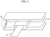
- the sealing-planned part in a sheet form is inevitably extended by pressurization.
- members pressurizing the sealing-planned part 21 at an upper portion and a lower portion have a shape corresponding to the sealing-planned part 21 in a plane, thereby protruding to an outer side of the sealing apparatus 20 when the sealing-planned part 21 is extended.
- the sealing-planned part since it is impossible to apply heat and pressure to the extended sealing-planned part, the sealing-planned part may not be sealed, and consequently, sealing force of a battery case may be low, and thus when the battery cell is used for a long time, leakage of electrolyte solution and penetration of water and foreign matters may occur by separation of sealing of the battery cell.
- the present invention provides a sealing apparatus having a novel structure in which not only the sealing-planned part but also the inevitably extended sealing-planned part in a sealing process are further able to be sealed.
- the sealing apparatus has a protrusion part, which extends from the sealing block toward a direction of an electrode assembly and in a direction opposite to the electrode assembly, and thus the sealing-planned part may be sealed by additionally applying heat and pressure to the sealing-planned part extending in the above-described directions.
- the sealing apparatus has a structure in which the application area of pressure and heat of the sealing blocks with respect to the sealing-planned part is substantially increased by the protrusion part, which is more effective at a portion of the electrode lead where an area to which heat is applicable is considerably narrow.
- a shape of the protrusion part may be a round structure including a polygon or a curve on a vertical cross section, and the shape may be selected in consideration of a thickness of the sealing-planned portion to be extended, an extended form of the sealing-planned part, etc.
- the sealing-planned part to be extended has a small area, but is extended in a relatively sharp shape at the time of pressurization.
- the protrusion part pressurizes the extended sealing-planned part
- the sealing-planned part is extended in a form in which an angled edge portion is curve, and thus a rounded structure including curves may be more suitable for extensive pressurization.
- the sealing-planned part to be extended has a large area and is extended in a relatively round shape at the time of pressurization.
- the protrusion part pressurizes the extended sealing-planned part
- the sealing-planned part is extended in an angled edge form in the round structure, and thus the protrusion part having a polygonal structure may be more effective for extensive pressurization.
- the protrusion part may also have a wedge-shaped structure in a plane.
- the protrusion part has a very sharply protruding shape in a 'V' shape, and has an advantage in that a sharpened edge of the protrusion part is able to more precisely pressurize the sealing-planned part to be extended in the 'V' shape along the electrode lead.
- An extension length of the protrusion part may be 5% to 30% relative to a width of the sealing-planned part.
- the extension length of the protrusion part means the maximum length of the protrusion part from an end portion of the sealing block.
- the extension length of the protrusion part When the extension length of the protrusion part is less than the above-described range, it is difficult to effectively pressurize the sealing-planned part to be extended, and a heat application range is also very limited, and thus it is not possible to achieve an intended effect of the present invention. Conversely, when the extension length of the protrusion part is more than the above-described range, it is not preferable since the extended sealing-planned part is further extended or is completely melted by heat and pressure, and thus bonding is not able to be performed. In consideration of the above description, the extension length of the protrusion part may be more preferably 15% to 20% relative to the width of the sealing-planned part.
- the sealing apparatus has a special structure capable of more tightly sealing the sealing-planned part adjacent to the electrode lead.
- a shape of the electrode lead and a detailed structure of the sealing blocks and the protrusion part for effectively sealing the sealing-planned part in consideration of the shape of the electrode lead will be described in detail through non-limiting examples described below.
- the electrode lead may include an electrically conductive lead member and a pair of insulating films attached in a form of locally surrounding the lead member; and the insulating films may include a surplus bonding part bonded to each other at both side end portions of the lead member.
- the sealing blocks may further bond the sealing-planned part and the insulating films that are in close contact with each other, and the protrusion parts may further bond the sealing-planned part extending along the end portion of the lead member and the insulating film exposed to the outside.
- the insulating film may be in close contact with the inner surface of the sealing-planned part in a state in which a portion of the insulating film is interposed between the sealing-planned parts.
- the sealing block may apply heat and pressure to the sealing-planned part to bond a portion of the sealing-planned part and the insulating film.
- the insulating film may be pushed in a protrusion direction of the lead member by pressure.
- the insulating film on which the protrusion part is exposed to the outside may be pressurized and fixed when the sealing block pressurizes the sealing-planned part, and thus it is possible not only to suppress a pushing phenomenon of the insulating film but also to bond the extended sealing-planned part to the insulating film exposed to the outside. Even if the insulating film is partially pushed, the insulating film may be immediately sealed with the sealing-planned part to be extended, by the protrusion part, and thus a phenomenon that the insulating film is completely deviated to the outer side of the sealing-planned part may be prevented.
- the sealing blocks may include a first block that pressurizes the sealing-planned part at an upper portion; and a second block that pressurizes the sealing-planned part at a lower portion, and the protrusion parts may be formed in the first block and the second block, respectively.
- the protrusion parts formed on the first block and the protrusion parts formed on the second block face each other in a state in which the first block and the second block face each other, and when the first block and the second block come in close contact with each other, the protrusion parts formed respectively on the blocks are also in close contact with each other.
- each of the first block and the second block includes a pair of first steps formed at positions corresponding to both side end portions of the electrode lead on a vertical cross section; and second steps extending from the first steps, respectively, and formed at positions corresponding to both side end portions of the surplus bonding part in the insulating film.
- the first steps may have a depth that approximately corresponds to or is smaller than a thickness of the lead member and the insulating film that is locally added to the lead member, and a width therebetween may approximately correspond to the width of the lead member.
- the first steps may have a shape of a recessed groove having the depth and the width, and the lead member and the insulating film may be inserted into the recessed groove formed by the first steps.
- the second steps may have a depth that approximately corresponds to or is smaller than a thickness of the surplus bonding part, and a width therebetween may be a length corresponding approximately to a length from an end portion of the surplus bonding part that is bonded at an end portion of one side of the lead member to an end portion of the surplus bonding part that is bonded at an end portion of the other side thereof.
- the second steps may have a shape of another recessed groove having the depth and width, and the surplus bonding parts may be inserted into the recessed groove.
- a material for forming the first block, the second block, and each of the protrusion parts is not particularly limited as long as it is a material capable of conducting heat, but more specifically, the material may be one or more selected from metals capable of having both strength and heat conduction such as stainless steel, steel, titanium, etc., and heat conductive metals such as aluminum, copper, lead, tin, etc.
- Inner portions of the first block, the second block, and the respective protrusion parts have a heating means such as a heater, a heating wire, or the like, for applying heat.
- the first block, the second block, and the respective protrusion parts may be heated by the heating means, and thus heat may be applied to the sealing-planned part and the insulating film that are in contact with the first block, the second block, and the protrusion parts.
- a plurality of heating means may be embedded inside the first and second steps, and thus the electrode lead and the sealing-planned part to be inserted into the recessed grooves formed by these steps may be quickly bonded by heating in a short time.
- the sealing-planned part may be more effectively bonded to the insulating film attached on the lead member.
- a portion of the sealing-planned part may be bent by the first step while the electrode lead is inserted between the first steps to thereby be in close contact with the insulating films that are attached to both side surfaces of the lead member, and then may be bonded thereto.
- a remaining portion of the sealing-planned part may be in close contact with the insulating films that are attached to an upper surface and a lower surface of the lead member in the electrode lead inserted between the first steps, and then may be bonded thereto.
- the sealing-planned part may be bonded to the insulating film at a side surface of the lead member in state in which the sealing-planned part is bent corresponding to the first steps formed on the first block and the second block. Due to this point, it should be noted that the sealing-planned part may enlarge a close contact area in a side surface direction of the lead member as well as an upper surface of the electrode lead to secure a wide heat application area for each block.
- the above-described sealing apparatus structure may utilize a very limited heat application area to be capable of firmly bonding the sealing-planned part with respect to the lead member and the insulating film, and preventing an undesired gap between the sealing-planned part and the lead member from occurring.
- a portion of the sealing-planned part may be bent by the second step while the insulating film is inserted between the second steps to thereby be in close contact with the both side end portions of the surplus bonding part, and then may be bonded thereto.
- a remaining portion of the sealing-planned part may be in close contact with an upper surface and a lower surface of the surplus bonding parts that are inserted between the second steps, and then may be bonded thereto.
- the sealing-planned part may be bonded to a side surface of the surplus bonding parts in a state in which the sealing-planned part is bent corresponding to the second steps formed on the first block and the second block. Due to this point, the sealing-planned part may enlarge a close contact area in a side surface direction of the surplus bonding parts as well as an upper surface of the surplus bonding parts to secure a wide heat application area for each block.
- the above-described sealing apparatus structure may utilize a very limited heat application area to be capable of firmly bonding the sealing-planned part with respect to the surplus bonding parts, and preventing an undesired gap between the sealing-planned part and the surplus bonding part from occurring.
- the protrusion parts of the first block and the second block include, in each of the first steps, a pair of first protrusion parts protruding toward the electrode assembly; and a pair of second protrusion parts protruding in opposition to the first protrusion parts, and the protrusion parts of the first block and the second block also further include, in each of the second steps, a pair of third protrusion parts protruding toward the electrode assembly; and a pair of fourth protrusion parts protruding in opposition to the third protrusion parts.
- the sealing-planned part extending in a direction of the electrode lead may be bent by the first steps while the electrode lead is inserted between the second protrusion parts to thereby be in close contact with the insulating films that are attached to the electrode lead, and then may be bonded thereto.
- the first protrusion parts may be formed so that the sealing-planned part extending in a direction of the electrode assembly is in close contact with the insulating films that are attached to the electrode lead, and then is bonded thereto.
- the sealing-planned part extended by the first block and the second block may be further bonded in a direction of the electrode lead and a direction of the electrode assembly by the first protrusion parts and the second protrusion parts, thereby more firmly bonding the electrode lead and the sealing-planned part adjacent thereto.
- the surplus bonding part of the insulating film may be inserted between the fourth protrusion parts, and the sealing-planned part extending in a direction of the electrode lead may be in close contact with the surplus bonding part while being bent so as to surround the surplus bonding part by the second steps, and then may be bonded thereto.
- the third protrusion parts may be formed so that the sealing-planned part extending in a direction of the electrode assembly is in close contact with the insulating films that are attached to the electrode lead, and then is bonded thereto.
- the extended sealing-planned part may be further bonded in the first protrusion parts to the fourth protrusion parts extending from the second steps, and due to this point, the sealing apparatus according to the present invention may more firmly bond the sealing-planned part.
- the battery cell may include a pouch type battery case of a laminate sheet; a non-aqueous electrolyte solution; and an electrode assembly including a cathode, an anode, and a separator, wherein the sealing-planned part of the battery case is thermally fused in a state in which the electrode assembly and the non-aqueous electrolyte solution are embedded in the battery case.
- the battery cell is not particularly limited in its kind, but specific examples thereof may include a lithium secondary battery having advantages such as high energy density, discharge voltage, and output stability, etc., such as a lithium ion (Li-ion) secondary battery, a lithium polymer (Li-polymer) secondary battery, a lithium ion polymer (Li-ion polymer) secondary battery, or the like.
- a lithium secondary battery having advantages such as high energy density, discharge voltage, and output stability, etc., such as a lithium ion (Li-ion) secondary battery, a lithium polymer (Li-polymer) secondary battery, a lithium ion polymer (Li-ion polymer) secondary battery, or the like.
- the lithium secondary battery may be composed of a cathode, an anode, a separator, and a lithium salt-containing non-aqueous electrolyte solution.
- the cathode may be manufactured, for example, by applying a mixture of a cathode active material, a conductive material, and a binder on a cathode current collector and/or an extended current collecting part, followed by drying.
- a filler may be further added to the mixture.
- the cathode current collector and/or the extended current collecting part is generally formed to have a thickness of 3 to 500 ⁇ m.
- the cathode current collector and the extended current collecting part are not particularly limited as long as they have electrical conductivity without causing a chemical change in the battery.
- stainless steel, aluminum, nickel, titanium, sintered carbon, or a surface-modified material with carbon, nickel, titanium, silver, or the like, on an aluminum surface or a stainless steel surface may be used.
- the cathode current collector and the extended current collecting part may have fine protrusions and depressions formed on a surface thereof to enhance bonding force of the cathode active material, and may be used in various forms such as films, sheets, foils, nets, porous bodies, foams, non-woven fabrics, etc.
- cathode active material may include layered compounds including lithium cobalt oxide (LiCoO 2 ), lithium nickel oxide (LiNiO 2 ), and the like, or compounds substituted with one or more transition metals; lithium manganese oxides represented by Chemical Formula Li 1+x Mn 2-x O 4 wherein x is 0 to 0.33, LiMnO 3 , LiMn 2 O 3 , LiMnO 2 , etc.; lithium copper oxides (Li 2 CuO 2 ); vanadium oxides such as LiV 3 O 8 , LiFe 3 O 4 , V 2 O 5 , Cu 2 V 2 O 7 , etc.; Ni-site type lithium nickel oxides represented by Chemical Formula LiNi 1-x M x O 2 wherein M is Co, Mn, Al, Cu, Fe, Mg, B or Ga, and x is 0.01 to 0.3; lithium manganese complex oxides represented by LiMn 2-x M x O 2 wherein M is Co, Ni, Fe, Cr, Zn or Ta, and
- the conductive material is generally added in an amount of 1 to 30 wt% based on the total weight of the mixture including the cathode active material.
- the conductive material is not particularly limited as long as it has electrical conductivity without causing a chemical change in the battery.
- Examples of the conductive material may include graphite such as natural graphite, and artificial graphite, or the like; carbon black such as carbon black, acetylene black, Ketjen black, channel black, furnace black, lamp black, and summer black, or the like; conductive fiber such as carbon fiber, metal fiber, or the like; metal powder such as carbon fluoride, aluminum, nickel powder, or the like; conductive whisker such as zinc oxide, potassium titanate, or the like; conductive metal oxide such as titanium oxide, or the like; conductive material such as polyphenylene derivative, or the like, may be used.
- the binder is a component which assists in bonding of the active material and the conductive material, etc., and bonding to the current collector, and is generally added in an amount of 1 to 30 wt% based on the total weight of the mixture containing the cathode active material.
- the binder may include polyvinylidene fluoride, polyvinyl alcohol, carboxymethylcellulose (CMC), starch, hydroxypropylcellulose, regenerated cellulose, polyvinylpyrrolidone, tetrafluoroethylene, polyethylene, polypropylene, ethylenepropylene-diene terpolymer (EPDM), sulfonated EPDM, styrene butylene rubber, fluorine rubber, various copolymers, etc.
- the filler is optionally used as a component for suppressing expansion of the cathode, and is not particularly limited as long as it is a fibrous material without causing a chemical change in the battery.
- the filler may include olefin-based polymers such as polyethylene, polypropylene, etc.; fibrous materials such as glass fibers and carbon fibers, etc.
- the anode may be manufactured by applying an anode active material on an anode current collector and/or an extended current collecting part, followed by drying. If required, the above-described components may be optionally included in the anode.
- the anode current collector and/or the extended current collecting part is generally formed to have a thickness of 3 to 500 ⁇ m.
- the anode current collector and/or the extended current collecting part are not particularly limited as long as they have electrical conductivity without causing a chemical change in the battery.
- copper, stainless steel, aluminum, nickel, titanium, sintered carbon, a surface-modified material with carbon, nickel, titanium, silver, or the like, on a copper surface or a stainless steel surface, or an aluminum-cadmium alloy may be used.
- the anode current collector and/or the extended current collecting part may have fine protrusions and depressions formed on a surface thereof to enhance bonding force of the anode active material, and may be used in various forms such as films, sheets, foils, nets, porous bodies, foams, non-woven fabrics, etc.
- anode active material may include carbons such as non-graphitized carbon, graphite-based carbon, etc.; metal complex oxides such as Li x Fe 2 O 3 (0 ⁇ x ⁇ 1), Li x WO 2 (0 ⁇ x ⁇ 1), Sn x Me 1-x Me' y O z (Me: Mn, Fe, Pb, Ge; Me': Al, B, P, Si, Group 1, Group 2 and Group 3 elements in the Periodic Table, halogen; 0 ⁇ x ⁇ 1; 1 ⁇ y ⁇ 3; 1 ⁇ z ⁇ 8), etc.; lithium metals; lithium alloys; silicon-based alloys; tin-based alloys; metal oxides such as SnO, SnO 2 , PbO, PbO 2 , Pb 2 O 3 , Pb 3 O 4 , Sb 2 O 3 , Sb 2 O 4 , Sb 2 O 5 , GeO, GeO 2 , Bi 2 O 3 , Bi 2 O
- the separator is interposed between the cathode and the anode, and as the separator, an insulating thin film having high ion permeability and mechanical strength is used.
- the separator generally has a pore diameter of 0.01 to 10 ⁇ m and generally has a thickness of 5 to 300 ⁇ m.
- olefin-based polymers such as polypropylene having chemical resistance and hydrophobicity; a sheet or a non-woven fabric made of glass fiber, polyethylene, or the like, is used.
- a solid electrolyte such as a polymer is used as the electrolyte, the solid electrolyte may also serve as the separator.
- the electrolyte solution may be a lithium salt-containing non-aqueous electrolyte solution, and may be formed of a non-aqueous electrolyte solution and a lithium salt.
- non-aqueous electrolyte solution may include non-aqueous organic solvents, organic solid electrolytes, inorganic solid electrolytes, etc., but the non-aqueous electrolyte solution is not limited thereto.
- non-aqueous organic solvent may include aprotic organic solvents such as N-methyl-2-pyrrolidinone, propylene carbonate, ethylene carbonate, butylene carbonate, dimethyl carbonate, diethyl carbonate, gamma-butyrolactone, 1,2-dimethoxy ethane, tetrahydroxy franc, 2-methyl tetrahydrofuran, dimethylsulfoxide, 1,3-dioxolane, formamide, dimethylformamide, dioxolane, acetonitrile, nitromethane, methyl formate, methyl acetate, phosphoric acid triester, trimethoxy methane, dioxolane derivative, sulfolane, methyl sulfolane
- organic solid electrolyte may include a polyethylene derivative, a polyethylene oxide derivative, a polypropylene oxide derivative, a phosphate ester polymer, poly agitation lysine, polyester sulfide, polyvinyl alcohol, polyvinylidene fluoride, and a polymer including an ionic dissociation group, etc.
- Examples of the inorganic solid electrolyte may include Li nitrides, Li halides, Li sulfates such as Li 3 N, Lil, Li 5 NI 2 , Li 3 N-LiI-LiOH, LiSiO 4 , LiSiO 4 -LiI-LiOH, Li 2 SiS 3 , Li 4 SiO 4 , Li 4 SiO 4 -LiI-LiOH, Li 3 PO 4 -Li 2 S-SiS 2 , etc.
- Li nitrides Li halides, Li sulfates such as Li 3 N, Lil, Li 5 NI 2 , Li 3 N-LiI-LiOH, LiSiO 4 , LiSiO 4 -LiI-LiOH, Li 2 SiS 3 , Li 4 SiO 4 , Li 4 SiO 4 -LiI-LiOH, Li 3 PO 4 -Li 2 S-SiS 2 , etc.
- the lithium salt is a material that is favorable to be dissolved in the non-aqueous electrolyte.
- pyridine triethylphosphite, triethanolamine, cyclic ether, ethylene diamine, n-glyme, hexaphosphoric triamide, nitrobenzene derivative, sulfur, quinone imine dye, N-substituted oxazolidinone, N,N-substituted imidazolidine, ethylene glycol dialkyl ether, ammonium salt, pyrrole, 2-methoxy ethanol, aluminum trichloride, etc., may be added to the non-aqueous electrolyte solution.
- a halogen-containing solvent such as carbon tetrachloride, ethylene trifluoride, or the like, may be further added.
- carbon dioxide gas may be further added or fluoro-ethylene carbonate (FEC), propene sultone (PRS), or the like, may be further added.
- the lithium salt-containing non-aqueous electrolyte solution may be prepared by adding a lithium salt such as LiPF 6 , LiClO 4 , LiBF 4 , LiN(SO 2 CF 3 ) 2 , or the like, to a mixed solvent including a cyclic carbonate of EC or PC which is a high-dielectric solvent and a linear carbonate of DEC, DMC or EMC which is a low viscosity solvent.
- a lithium salt such as LiPF 6 , LiClO 4 , LiBF 4 , LiN(SO 2 CF 3 ) 2 , or the like
- a mixed solvent including a cyclic carbonate of EC or PC which is a high-dielectric solvent and a linear carbonate of DEC, DMC or EMC which is a low viscosity solvent.
- a battery pack including at least one battery cell, or a battery module including at least two battery packs, or a device including at least one battery cell.
- the device may be, but is not limited to, a mobile device such as, for example, a notebook computer, a netbook, a tablet PC or a smart pad, or a large device such as an electric vehicle, a hybrid electric vehicle, a plug-in hybrid electric vehicle, or the like.
- a mobile device such as, for example, a notebook computer, a netbook, a tablet PC or a smart pad, or a large device such as an electric vehicle, a hybrid electric vehicle, a plug-in hybrid electric vehicle, or the like.
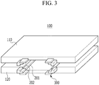
- FIG. 3 shows a schematic view of a sealing apparatus according to one example of the present invention
- FIG. 4 shows a plan view of the sealing apparatus
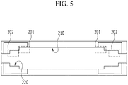
- FIG. 5 shows a vertical cross-sectional view of the sealing apparatus.
- the sealing apparatus 100 is a sealing block for applying heat and pressure to the sealing-planned part 150 of the battery cell, and includes a first block 110 and a second block 120 opposing each other at an upper part and a lower part.
- Each of the first block 110 and the second block 120 includes a pair of protrusion parts 300 extending outwardly from one side end portion and a pair of protrusion parts (not shown) extending outwardly from the other side end portion.
- the protrusion parts 300 extend from steps 201 and 202 formed on the first block 110 and the second block 120.
- the steps 201 and 202 into which protruding portions of the electrode leads 50 are inserted may be formed in the battery cell having surfaces on which the first block 110 and the second block 120 face each other.
- the steps 201 and 202 structures of the electrode lead 50 shown in FIGS. 5 and 6 will be described.
- the electrode lead 50 includes an electrically conductive lead member 51 and a pair of insulating films 52 attached in a form of locally surrounding the lead member 51.
- the insulating film 52 may include a surplus bonding part 52a bonded to each other at both side end portions of the lead member 51.
- the electrode lead 50 means the lead member 51 in a state in which the insulating film 52 is added, but this concept may include or may not include the surplus bonding part 52a of the insulating film 52.
- the first block 110 and the second block 120 may have an inner surface shape corresponding so that the electrode lead 50, that is, the lead member 51 in a state in which the insulating film 52 is added is able to be inserted.
- steps include a pair of first steps 201 formed at positions corresponding to both side end portions of the electrode lead 50, on the vertical cross section.
- the lead member 51 in a state in which the insulating film 52 is added may be inserted between the first steps 201 together with the sealing-planned part 150 and a portion between the first steps 201 may be referred to as a first recessed groove 210.
- first block and the second block 120 further include second steps 202 formed at positions corresponding to both side end portions of the surplus bonding part 52a in the insulating film 52, on the vertical cross section, respectively, and the second steps 202 may extend from the first steps 201, respectively.
- the surplus bonding part 52a may be inserted between the second steps 202 together with the sealing-planned part 150, and a portion between the second steps 202 may be referred to as a second recessed groove 220.
- the protrusion parts protrude from the first steps 201 and the second steps 202, respectively.
- the protrusion parts include, in each of the first steps 201, a pair of first protrusion parts 310a and 310b protruding toward the electrode assembly 60; and a pair of second protrusion parts 312a and 312b protruding in opposition to the first protrusion parts 310a and 310b.
- the protrusion parts also include, in each of the second steps 202, a pair of third protrusion parts 320a and 320b protruding toward the electrode assembly 60; and a pair of fourth protrusion parts 322a and 322b protruding in opposition to the third protrusion parts 320a and 320b.
- each of the first protrusion parts 310a and 310b and the second protrusion parts 312a and 312b may include a step extending from the first steps 201
- each of the third protrusion parts 320a and 320b and the fourth protrusion parts 322a and 322b may include a step extending from the second steps 202.
- Heating means may be provided in an inner part of each of the protrusion parts 310a, 310b, 312a, 312b, 320a, 320b, 322a, and 322b so that heat is applicable to the sealing-planned part 150, and the heating means may be the same as or different from the heating means provided in the first block 110 and the second block 120.
- the electrode lead 50 together with the sealing-planned part 150 may be inserted between the first steps 201.
- a portion of the sealing-planned part 150 may be bent by the first step to be pressurized and to be in close contact with the insulating film 52 that is attached to both side surfaces of the lead member 51.
- the insulating film 52 and the sealing-planned part 150 may be bonded in a side surface direction of the electrode lead 50 by heat applied to inner surfaces of the first block 110 and the second block 120.
- the sealing-planned part 150 inserted into and in close contact with the first recessed groove 210 may be in close contact with the insulating film 52 attached to the upper and lower surfaces of the lead member 51 in the electrode lead 50, and then may be bonded thereto.
- the sealing-planned part 150 may be bonded to the insulating film 52 at a side surface of the lead member 51 in state in which the sealing-planned part 150 is bent corresponding to the first steps 201 formed on the first block 110 and the second block 120. Due to this point, it should be noted that the sealing-planned part 150 may enlarge a close contact area in a side surface direction of the lead member 51 as well as an upper surface of the electrode lead 50 to secure a wide heat application area for each block.
- the insulating film 52 may be inserted between the second steps 202.
- a portion of the sealing-planned part 150 may be bent by the second step, pressurized and in close contact with both side end portions of the surplus bonding portions 52a, and then may be bonded by heat. Further, the sealing-planned part 150 inserted into and in close contact with the second recessed groove 220 may be in close contact with the upper and lower surfaces of the surplus bonding parts 52a, and then may be bonded thereto.
- the sealing-planned part 150 may be bonded to a side surface of the surplus bonding parts 52a in a state in which the sealing-planned part 150 is bent corresponding to the second steps 202 formed on the first block 110 and the second block 120. Due to this point, the sealing-planned part 150 may enlarge a close contact area in a side surface direction of the surplus bonding parts 52a as well as an upper surface of the surplus bonding parts 52a to secure a wide heat application area for each block.
- the electrode lead 50 and the adjacent sealing-planned part 150 may be further bonded at the protrusion part at the same time as the above-described process.
- the electrode lead 50 together with the sealing-planned part 150 may be inserted between the first steps of 201, and portions 152, 154, 156, and 158 of the sealing-planned part 150 may be extended in a direction of the electrode lead 50 by a pressurization force between the first recessed groove 210 and the electrode lead 50.
- the extension is actually caused very locally.
- the sealing-planned part 150 tends to be extended at a portion where the sealing-planned part 150 is bent by the step.
- the sealing-planned part 150 extended by the heat from the protrusion part 300 may be bonded.
- the sealing-planned parts 152 and 156 extending in the direction of the electrode lead 50 may be bent by the first steps 201 on the second protrusion parts 312a and 312b while the electrode lead 50 is inserted between the second protrusion parts 312a and 312b to thereby be in close contact with the insulating film 52 attached to the electrode lead 50, and then may be further bonded thereto.
- the portion 154 and 158 of the sealing-planned part 150 may be extended in a direction of the electrode assembly 60 by the pressurization force between the first recessed groove 210 and the electrode lead 50, wherein the first protrusion parts 310a and 310b may be formed so that the sealing-planned part 150 extending in a direction of the electrode assembly 60 is in close contact with the insulating film 52 that is attached to the electrode lead 50, and then is bonded thereto.
- the sealing-planned part 150 extended by the first block 110 and the second block 120 may be further bonded in the direction of the electrode lead 50 and the direction of the electrode assembly 60 by the first protrusion parts 310a and 310b and the second protrusion parts 312a and 312b, thereby more firmly bonding the electrode lead 50 and the sealing-planned part 150 adjacent thereto.
- the surplus bonding part 52a of the insulating film 52 may be inserted between the fourth protrusion parts 322a and 322b, and the sealing-planned part 150 extending in a direction of the electrode lead 50 may be in contact with the surplus bonding part 52a while being bent so as to surround the surplus bonding part 52a by the second steps 202, and then may be bonded thereto.
- the third protrusion parts 320a and 320b may be formed so that the sealing-planned part 150 extending in a direction of the electrode assembly 60 is in close contact with the insulating films 52 that are attached to the electrode lead 50, and then is bonded thereto.
- the sealing apparatus 100 may have a structure in which an application area of pressure and heat is substantially increased by sealing blocks with respect to the sealing-planned part 150 by the protrusion part, and may have a structural advantage in that these protrusion parts may further apply heat and pressure to the sealing-planned part 150 extending in the direction of the electrode assembly 60 and the direction opposite thereto, thereby sealing the sealing-planned part 150, and thus the sealing-planned part 150 may be more firmly bonded.
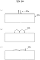
- FIG. 9 is a schematic view showing various shapes of protrusion parts according to another exemplary embodiment of the present invention.
- the protrusion parts may have a wedge shape, a polygonal shape, or a round shape on a vertical cross section.
- the protrusion part 300a having a wedge shape has a very sharply protruding shape in a 'V' shape, and has an advantage in that a sharpened edge of the protrusion part is able to more precisely pressurize the sealing-planned part to be extended in the 'V' shape along the electrode lead.
- the protrusion part 300b having a polygonal shape is preferable when a thickness of the sealing-planned part is very thick.
- the thick sealing-planned part has a large area and is extended in a round structure.
- the protrusion part 300b pressurizes the extended sealing-planned part, the sealing-planned part is extended in an angled edge form in the round structure, and thus the protrusion part 300b having a polygonal shape may more extensively pressurize the sealing-planned part.
- the sealing-planned part to be extended has a small area, but is extended in a relatively sharp shape at the time of pressurization.
- the protrusion part 300c having a round structure pressurizes the angled edge portion of the extended sealing-planned part by the round structure, thereby preventing the sealing-planned part from being extended beyond the protrusion part.
- the sealing apparatus may have a structure in which an application area of pressure and heat is substantially increased by sealing blocks with respect to the sealing-planned part by the protrusion part, and may have a structural advantage in that these protrusion parts may further apply heat and pressure to the sealing-planned part extending in the direction of the electrode assembly and the direction opposite thereto, thereby sealing the sealing-planned part, and thus the sealing-planned part may be more firmly bonded.
Landscapes
- Chemical & Material Sciences (AREA)
- Chemical Kinetics & Catalysis (AREA)
- Electrochemistry (AREA)
- General Chemical & Material Sciences (AREA)
- Engineering & Computer Science (AREA)
- Mechanical Engineering (AREA)
- Manufacturing & Machinery (AREA)
- Materials Engineering (AREA)
- Sealing Battery Cases Or Jackets (AREA)
- Connection Of Batteries Or Terminals (AREA)
- Secondary Cells (AREA)
Claims (9)
- Dichtungsvorrichtung (100) zum Abdichten eines zum Abdichten vorgesehenen Teils (150) eines Batteriegehäuses, welcher eine vorstehende Elektrodenleitung (50) umfasst, durch Aufbringen von Wärme und Druck auf eine Batteriezelle, welche eine Struktur aufweist, in welcher eine Elektrodenanordnung (60) und eine Elektrolytlösung in einem Batteriegehäuse aus einer Laminatschicht eingebettet sind,wobei die Elektrodenleitung (50) ein elektrisch leitfähiges Leitungselement (51) und ein Paar von Isolierfilmen (52) umfasst, welche in einer derartigen Form angeordnet sind, dass sie das Leitungselement (51) lokal umgeben;wobei die Isolierfilme (52) einen Überschussverbindungsteil (52a) umfassen, welcher an beiden seitlichen Endabschnitten des Leitungselements (51) miteinander verbunden ist;wobei in der Elektrodenleitung (50), in einem Zustand, in welchem ein Abschnitt der Isolierfilme (52) in engem Kontakt mit einer inneren Fläche des zum Abdichten vorgesehenen Teils (150) ist, ein verbleibender Abschnitt der Elektrodenleitung (50) von dem Isolierfilm (52) nach außen vorsteht;wobei die Dichtungsvorrichtung (100) ein Paar von Dichtungsblöcken umfasst, welche dafür geeignet sind, durch Aufbringen von Druck und Wärme auf den zum Abdichten vorgesehenen Teil (150) an einem oberen Abschnitt und einem unteren Abschnitt des zum Abdichten vorgesehenen Teils den zum Abdichten vorgesehenen Teil (150) und die Elektrodenleitung (50) zu verbinden, welche von dem zum Abdichten vorgesehenen Teil (150) vorsteht, wobei die Elektrodenleitung (50) zwischen dem zum Abdichten vorgesehenen Teil (150) eingefügt ist;wobei die Dichtungsblöcke mit zwei oder mehr vorstehenden Teilen (300) gebildet sind, welche sich jeweils in einer Richtung hin zu der Elektrodenanordnung (60) und in einer der Elektrodenanordnung (60) entgegengesetzten Richtung erstrecken;wobei die Dichtungsblöcke ferner dafür geeignet sind, den zum Abdichten vorgesehenen Teil (150) und die Isolierfilme (52) zu verbinden, welche in engem Kontakt zueinander sind, und wobei die vorstehenden Teile (300) ferner dafür geeignet sind, den zum Abdichten vorgesehenen Teil (150), welcher sich entlang des Endabschnitts des Leitungselements (51) erstreckt, und den Isolierfilm (52) zu verbinden, welcher von dem zum Abdichten vorgesehenen Teil (150) zu der Außenseite freigelegt ist;und wobei der vorstehende Teil (300) ferner dafür geeignet ist, durch Wärme und Druck der Dichtungsblöcke Wärme und Druck auf einen entsprechenden Abschnitt des zum Abdichten vorgesehenen Teils (150) aufzubringen, welcher sich entlang eines Endabschnitts der Elektrodenleitung (50) erstreckt, wodurch der sich erstreckende, zum Abdichten vorgesehene Teil (150) abgedichtet wird,wobei die Dichtungsblöcke umfassen:einen ersten Block (110), welcher dazu eingerichtet ist, den zum Abdichten vorgesehenen Teil (150) an einem oberen Abschnitt mit Druck zu beaufschlagen; undeinen zweiten Block (120), welcher dazu eingerichtet ist, den zum Abdichten vorgesehenen Teil (150) an einem unteren Abschnitt mit Druck zu beaufschlagen,wobei die vorstehenden Teile (300) in dem ersten Block (110) bzw. dem zweiten Block (120) gebildet sind,wobei innere Abschnitte des ersten Blocks, des zweiten Blocks und der jeweiligen vorstehenden Teile Heizmittel aufweisen,wobei sich die vorstehenden Teile beider Dichtungsblöcke von dem Dichtungsblock in beide Richtungen erstrecken, welche senkrecht zu der Richtung sind, in welcher die Dichtungsblöcke einander gegenüberliegen,wobei die vorstehenden Teile eines ersten und eines zweiten Dichtungsblocks, welche einander gegenüberliegen, entlang der Richtung einander zugewandt sind, in welcher die Dichtungsblöcke einander gegenüberliegen,wobei sowohl der erste Block (110) als auch der zweite Block (120) ein Paar erster Stufen (201), welche an Positionen gebildet sind, welche in einem Querschnitt senkrecht zu der Richtung, in welcher die Dichtungsblöcke einander gegenüberliegen, beiden seitlichen Endabschnitten der Elektrodenleitung (50) entsprechen; undzweite Stufen (202) umfasst, welche sich jeweils von den ersten Stufen (201) in einer Richtung parallel zu der Richtung erstrecken, in welcher die Dichtungsblöcke einander gegenüberliegen, und welche an Positionen gebildet sind, welche beiden seitlichen Endabschnitten des Überschussverbindungsteils (52a) in dem Isolierfilm (52) entsprechen, undwobei die vorstehenden Teile (300) des ersten Blocks (110) und des zweiten Blocks (120), in jeder der ersten Stufen (201),ein Paar erster vorstehender Teile (310a, 310b), welche in Richtung der Elektrodenanordnung (60) vorstehen; undein Paar zweiter vorstehender Teile (312a, 312b) umfassen, welche entgegengesetzt zu den ersten vorstehenden Teilen (310a, 310b) vorstehen, undwobei die vorstehenden Teile des ersten Blocks (110) und des zweiten Blocks (120) ferner auch, in jeder der zweiten Stufen (202),ein Paar dritter vorstehender Teile (320a, 320b), welche in Richtung der Elektrodenanordnung (60) vorstehen; undein Paar vierter vorstehender Teile (322a, 322b) umfassen, welche entgegengesetzt zu den dritten vorstehenden Teilen (320a, 320b) vorstehen.
- Dichtungsvorrichtung (100) nach Anspruch 1, wobei: der erste Block (110) und der zweite Block (120) dafür geeignet sind, den zum Abdichten vorgesehenen Teil (150) derart mit Druck zu beaufschlagen, dass ein Abschnitt des zum Abdichten vorgesehenen Teils (150) durch die erste Stufe gebogen wird, während die Elektrodenleitung (50) zwischen die ersten Stufen (201) eingesetzt wird, um dadurch in engem Kontakt mit den Isolierfilmen (52) zu sein, welche an beiden seitlichen Flächen des Leitungselements (51) angebracht sind, und dann damit verbunden wird.
- Dichtungsvorrichtung (100) nach Anspruch 2, wobei: ein verbleibender Abschnitt des zum Abdichten vorgesehenen Teils (150) in engem Kontakt mit den Isolierfilmen (52) ist, welche an einer oberen Fläche und einer unteren Fläche des Leitungselements (51) in der Elektrodenleitung (50) angebracht sind, welche zwischen die ersten Stufen (201) einsetzbar ist, und dann dazu in der Lage ist, damit verbunden zu werden.
- Dichtungsvorrichtung (100) nach Anspruch 1, wobei: der erste Block (110) und der zweite Block (120) dafür geeignet sind, den zum Abdichten vorgesehenen Teil (150) derart mit Druck zu beaufschlagen, dass ein Abschnitt des zum Abdichten vorgesehenen Teils (150) durch die zweite Stufe gebogen wird, während der Isolierfilm (52) zwischen die zweiten Stufen (202) eingesetzt wird, um dadurch in engem Kontakt mit den beiden seitlichen Endabschnitten des Überschussverbindungsteils (52a) zu sein, und dann damit verbunden wird.
- Dichtungsvorrichtung (100) nach Anspruch 4, wobei: ein verbleibender Abschnitt des zum Abdichten vorgesehenen Teils (150) in engem Kontakt mit einer oberen Fläche und einer unteren Fläche der Überschussverbindungsteile (52a) ist, welche zwischen die ersten Stufen (201) einsetzbar sind, und dann dazu in der Lage ist, damit verbunden zu werden.
- Dichtungsvorrichtung (100) nach Anspruch 1, wobei: der erste Block (110) und der zweite Block (120) dafür geeignet sind, den zum Abdichten vorgesehenen Teil (150) derart mit Druck zu beaufschlagen, dass der zum Abdichten vorgesehene Teil (150), welcher sich in einer Richtung der Elektrodenleitung (50) erstreckt, durch die ersten Stufen (201) gebogen wird, während die Elektrodenleitung (50) zwischen die zweiten vorstehenden Teile eingesetzt wird, um dadurch in engem Kontakt mit den Isolierfilmen (52) zu sein, welche an der Elektrodenleitung (50) angebracht sind, und dann damit verbunden wird.
- Dichtungsvorrichtung (100) nach Anspruch 1, wobei: der erste Block (110) und der zweite Block (120) dafür geeignet sind, den zum Abdichten vorgesehenen Teil (150) derart mit Druck zu beaufschlagen, dass die ersten vorstehenden Teile derart gebildet werden, dass der zum Abdichten vorgesehene Teil (150), welcher sich in einer Richtung der Elektrodenanordnung (60) erstreckt, in engem Kontakt mit den Isolierfilmen (52) ist, welche an der Elektrodenleitung (50) angebracht sind, und dann damit verbunden wird.
- Dichtungsvorrichtung (100) nach Anspruch 1, wobei: der erste Block (110) und der zweite Block (120) dafür geeignet sind, den zum Abdichten vorgesehenen Teil (150) derart mit Druck zu beaufschlagen, dass der Überschussverbindungsteil (52a) des Isolierfilms (52) zwischen den vierten vorstehenden Teilen eingesetzt wird und der zum Abdichten vorgesehene Teil (150), welcher sich in einer Richtung der Elektrodenleitung (50) erstreckt, in engem Kontakt mit dem Überschussverbindungsteil (52a) ist, während er durch die zweiten Stufen (202) derart gebogen wird, dass er den Überschussverbindungsteil (52a) umgibt, und dann damit verbunden wird.
- Dichtungsvorrichtung (100) nach Anspruch 1, wobei: der erste Block (110) und der zweite Block (120) dafür geeignet sind, den zum Abdichten vorgesehenen Teil (150) derart mit Druck zu beaufschlagen, dass die dritten vorstehenden Teile (320a, 320b) derart gebildet werden, dass der zum Abdichten vorgesehene Teil (150), welcher sich in einer Richtung der Elektrodenanordnung (60) erstreckt, in engem Kontakt mit den Isolierfilmen (52) ist, welche an der Elektrodenleitung (50) angebracht sind, und dann damit verbunden wird.
Priority Applications (1)
| Application Number | Priority Date | Filing Date | Title |
|---|---|---|---|
| PL16876040T PL3340334T3 (pl) | 2015-12-16 | 2016-12-15 | Urządzenie uszczelniające do komory akumulatora o zwiększonej powierzchni przykładania nacisku i ciepła |
Applications Claiming Priority (2)
| Application Number | Priority Date | Filing Date | Title |
|---|---|---|---|
| KR1020150179813A KR101947149B1 (ko) | 2015-12-16 | 2015-12-16 | 가압과 열 인가 면적이 증대된 전지케이스의 밀봉 장치 |
| PCT/KR2016/014699 WO2017105098A1 (ko) | 2015-12-16 | 2016-12-15 | 가압과 열 인가 면적이 증대된 전지케이스의 밀봉 장치 |
Publications (3)
| Publication Number | Publication Date |
|---|---|
| EP3340334A1 EP3340334A1 (de) | 2018-06-27 |
| EP3340334A4 EP3340334A4 (de) | 2018-07-04 |
| EP3340334B1 true EP3340334B1 (de) | 2021-03-10 |
Family
ID=59057209
Family Applications (1)
| Application Number | Title | Priority Date | Filing Date |
|---|---|---|---|
| EP16876040.3A Active EP3340334B1 (de) | 2015-12-16 | 2016-12-15 | Dichtungsvorrichtung für batteriegehäuse mit erhöhtem druck- und wärmeanwendungsbereich |
Country Status (7)
| Country | Link |
|---|---|
| US (1) | US10784476B2 (de) |
| EP (1) | EP3340334B1 (de) |
| JP (1) | JP6650039B2 (de) |
| KR (1) | KR101947149B1 (de) |
| CN (1) | CN108140759B (de) |
| PL (1) | PL3340334T3 (de) |
| WO (1) | WO2017105098A1 (de) |
Cited By (1)
| Publication number | Priority date | Publication date | Assignee | Title |
|---|---|---|---|---|
| EP4564542A1 (de) | 2023-11-29 | 2025-06-04 | LG Energy Solution, Ltd. | Dichtungsblock, dichtungsvorrichtung und sekundärbatterie |
Families Citing this family (20)
| Publication number | Priority date | Publication date | Assignee | Title |
|---|---|---|---|---|
| KR102364469B1 (ko) * | 2018-12-07 | 2022-02-17 | 주식회사 엘지에너지솔루션 | 두께의 편차가 있는 전지케이스용 라미네이트 시트 및 이를 이용하여 제조된 파우치형 전지케이스 |
| KR102549539B1 (ko) * | 2019-03-28 | 2023-06-29 | 주식회사 엘지에너지솔루션 | 이차전지용 실링장치 및 실링방법 |
| JP7398050B2 (ja) * | 2020-02-04 | 2023-12-14 | トヨタ自動車株式会社 | ラミネート電池およびその製造方法 |
| KR102779856B1 (ko) | 2020-02-13 | 2025-03-12 | 주식회사 엘지에너지솔루션 | 이차전지 가압장치 및 가압방법 |
| JP7328167B2 (ja) * | 2020-03-13 | 2023-08-16 | 本田技研工業株式会社 | 固体蓄電装置及びその製造方法 |
| EP4109612B1 (de) * | 2020-03-25 | 2024-10-16 | LG Energy Solution, Ltd. | Vorrichtung und verfahren zur herstellung von einheitszellen |
| WO2022050616A1 (ko) * | 2020-09-07 | 2022-03-10 | 주식회사 엘지에너지솔루션 | 이차전지, 이차전지 제조장치 및 제조방법 |
| KR20220057098A (ko) | 2020-10-29 | 2022-05-09 | 주식회사 엘지에너지솔루션 | 파우치형 전지 제조 장치 |
| MX2023006080A (es) * | 2020-12-02 | 2023-06-06 | Nestle Sa | Sellado a presion de multiples etapas de sustratos metalizados. |
| CN116325259A (zh) * | 2020-12-23 | 2023-06-23 | 株式会社Lg新能源 | 制造电极组件的方法、其中使用的密封单元以及由密封单元制造的电极组件 |
| KR102802113B1 (ko) * | 2020-12-23 | 2025-05-02 | 주식회사 엘지에너지솔루션 | 전극조립체의 제조방법, 그에 사용되는 실링 유닛, 및 그 실링 유닛에 의하여 제조된 전극조립체 |
| KR102917120B1 (ko) | 2021-02-09 | 2026-01-22 | 주식회사 엘지에너지솔루션 | 전지셀 제조 장치 |
| CN113422161A (zh) * | 2021-06-09 | 2021-09-21 | 宁德新能源科技有限公司 | 电化学装置及电子装置 |
| KR102657917B1 (ko) * | 2021-07-06 | 2024-04-16 | 주식회사 엘지에너지솔루션 | 전지셀 및 이를 제조하는 전지셀 제조 장치 |
| ES3045146T3 (en) * | 2021-07-06 | 2025-11-27 | Lg Energy Solution Ltd | Battery cell and battery cell manufacturing apparatus for manufacturing same |
| KR102835534B1 (ko) * | 2021-10-22 | 2025-07-17 | 주식회사 엘지에너지솔루션 | 간격 조정장치 및 그를 포함하는 이차전지용 실링설비 |
| ES3030548T3 (en) | 2021-11-30 | 2025-06-30 | Lg Energy Solution Ltd | Pouch-type battery and sealing device for pouch-type battery |
| KR20230080589A (ko) | 2021-11-30 | 2023-06-07 | 주식회사 엘지에너지솔루션 | 파우치형 전지의 밀봉장치 |
| KR20230081209A (ko) * | 2021-11-30 | 2023-06-07 | 에스케이온 주식회사 | 배터리 셀 실링 장치 |
| EP4459690A4 (de) * | 2021-12-29 | 2025-09-10 | Dongguan Amperex Tech Ltd | Elektrochemische vorrichtung und elektronische vorrichtung |
Family Cites Families (20)
| Publication number | Priority date | Publication date | Assignee | Title |
|---|---|---|---|---|
| JPH06163014A (ja) * | 1992-11-24 | 1994-06-10 | Yuasa Corp | 薄形電池とその製造方法 |
| KR100676989B1 (ko) * | 2000-01-26 | 2007-01-31 | 다이니폰 인사츠 가부시키가이샤 | 히트실링장치, 히트실링방법, 엠보스성형방법, 워크압압장치 및 워크 |
| JP2001266952A (ja) * | 2000-03-23 | 2001-09-28 | Sony Corp | リチウムイオン電池およびその製造方法 |
| JP2005353503A (ja) | 2004-06-14 | 2005-12-22 | Sii Micro Parts Ltd | 薄型電気化学セル |
| KR100571269B1 (ko) * | 2004-09-22 | 2006-04-13 | 삼성에스디아이 주식회사 | 이차전지용 파우치 및 파우치형 이차전지 |
| JP2006147230A (ja) * | 2004-11-17 | 2006-06-08 | Sony Corp | 電池および電池製造方法 |
| JP5082263B2 (ja) | 2006-03-10 | 2012-11-28 | 日本電気株式会社 | フィルム外装電気デバイスの製造方法 |
| JP4952658B2 (ja) * | 2008-06-02 | 2012-06-13 | ソニー株式会社 | 電池素子外装部材、及びこれを用いた非水電解質二次電池 |
| KR101452021B1 (ko) | 2010-10-14 | 2014-10-23 | 주식회사 엘지화학 | 파우치형 이차 전지의 실링장치 |
| KR101304870B1 (ko) * | 2010-12-02 | 2013-09-06 | 주식회사 엘지화학 | 전지셀의 제조방법 및 이를 이용하여 생산되는 전지셀 |
| KR20120126932A (ko) | 2011-05-13 | 2012-11-21 | 에스케이이노베이션 주식회사 | 파우치형 이차전지의 실링방법 및 실링장치 |
| JP2013026173A (ja) * | 2011-07-26 | 2013-02-04 | Sanyo Electric Co Ltd | ラミネート外装電池 |
| JP5909985B2 (ja) * | 2011-10-17 | 2016-04-27 | ソニー株式会社 | 電池および電池の製造方法ならびに電池パック、電子機器、電動車両、蓄電装置および電力システム |
| JP5561315B2 (ja) * | 2012-06-18 | 2014-07-30 | 日本電気株式会社 | フィルム外装電気デバイス |
| CN202888255U (zh) * | 2012-11-12 | 2013-04-17 | 微宏动力系统(湖州)有限公司 | 软包装电池封条 |
| CN104584259B (zh) * | 2012-12-28 | 2017-03-15 | 株式会社Lg 化学 | 用于密封二次电池的袋状壳体的设备和方法 |
| JP6019224B2 (ja) * | 2013-05-23 | 2016-11-02 | 日産自動車株式会社 | ラミネート型二次電池の製造方法および製造装置 |
| KR101763980B1 (ko) * | 2013-08-30 | 2017-08-01 | 주식회사 엘지화학 | 파우치형 이차전지의 실링 툴 |
| JP6851131B2 (ja) * | 2013-12-04 | 2021-03-31 | 株式会社半導体エネルギー研究所 | 可撓性を有する二次電池 |
| KR20150071918A (ko) * | 2013-12-19 | 2015-06-29 | 주식회사 엘지화학 | 이차전지의 실링장치 및 실링방법 |
-
2015
- 2015-12-16 KR KR1020150179813A patent/KR101947149B1/ko active Active
-
2016
- 2016-12-15 CN CN201680057724.7A patent/CN108140759B/zh active Active
- 2016-12-15 JP JP2018531283A patent/JP6650039B2/ja active Active
- 2016-12-15 WO PCT/KR2016/014699 patent/WO2017105098A1/ko not_active Ceased
- 2016-12-15 PL PL16876040T patent/PL3340334T3/pl unknown
- 2016-12-15 EP EP16876040.3A patent/EP3340334B1/de active Active
- 2016-12-15 US US15/760,817 patent/US10784476B2/en active Active
Non-Patent Citations (1)
| Title |
|---|
| None * |
Cited By (1)
| Publication number | Priority date | Publication date | Assignee | Title |
|---|---|---|---|---|
| EP4564542A1 (de) | 2023-11-29 | 2025-06-04 | LG Energy Solution, Ltd. | Dichtungsblock, dichtungsvorrichtung und sekundärbatterie |
Also Published As
| Publication number | Publication date |
|---|---|
| EP3340334A4 (de) | 2018-07-04 |
| JP2018530137A (ja) | 2018-10-11 |
| EP3340334A1 (de) | 2018-06-27 |
| KR20170071759A (ko) | 2017-06-26 |
| US10784476B2 (en) | 2020-09-22 |
| CN108140759B (zh) | 2020-11-03 |
| PL3340334T3 (pl) | 2021-07-05 |
| KR101947149B1 (ko) | 2019-02-13 |
| WO2017105098A1 (ko) | 2017-06-22 |
| US20180261807A1 (en) | 2018-09-13 |
| JP6650039B2 (ja) | 2020-02-19 |
| CN108140759A (zh) | 2018-06-08 |
Similar Documents
| Publication | Publication Date | Title |
|---|---|---|
| EP3340334B1 (de) | Dichtungsvorrichtung für batteriegehäuse mit erhöhtem druck- und wärmeanwendungsbereich | |
| EP3185346A1 (de) | Elektrodenanordnung mit raumteil für laschen-leitungs-kupplungsteil von elektrodenlaschen und elektrodenleitung | |
| KR102143366B1 (ko) | 곡면 엣지를 가진 전지셀 케이스 및 이의 제조 장치 | |
| KR101833540B1 (ko) | 가스 배출 수단을 포함하는 전지셀 | |
| KR102096817B1 (ko) | 노칭부를 포함하는 전극 시트를 이용하여 전극판을 제조하는 방법 | |
| KR102197377B1 (ko) | 비대칭 구조의 전극조립체 수납부를 포함하는 파우치형 전지셀 | |
| KR102066909B1 (ko) | 둥근 형태로 전극 리드를 가공할 수 있는 리드 가공 장치 및 이를 이용하여 가공된 전극 리드를 포함하는 가공된 전지셀 | |
| KR101752329B1 (ko) | 안전성이 향상된 이차전지 | |
| EP2922135B1 (de) | Batteriezelle mit amorpher struktur | |
| KR102026292B1 (ko) | 활물질 로딩량의 구배를 가진 전극을 포함하는 전극조립체 | |
| KR20150125263A (ko) | 전지케이스용 실링 장치 및 이를 사용하여 생산되는 전지셀 | |
| EP3605657B1 (de) | Batteriemodul und verfahren zur herstellung davon | |
| EP3370281B1 (de) | Elektrode mit elektrodenstromkollektor einer dreidimensionalen netzwerkstruktur | |
| US10868285B2 (en) | Pouch type battery cell including electrode lead of bending structure | |
| KR102082467B1 (ko) | 집전체 중심 부위에 높은 활물질 로딩량을 가지는 전극을 포함하는 전극조립체 | |
| KR102164576B1 (ko) | 전극조립체 제조방법 및 이를 사용하여 제조되는 전극조립체 | |
| KR20170063222A (ko) | 가스 트랩 현상을 개선시킨 이차전지 | |
| KR20160076735A (ko) | 전극 탭-리드 결합부의 안정성이 향상된 이차전지 | |
| KR102070907B1 (ko) | 충방전 시 발생하는 가스를 수용할 수 있는 잉여부를 포함하는 전지셀 | |
| KR20160074209A (ko) | 각형 만곡 이차전지 및 이의 제조방법 | |
| KR102120084B1 (ko) | 전극 리드 예열 방식의 전지셀 제조 방법 | |
| KR102025564B1 (ko) | 전지 소자들 사이에 개재되어 있는 단위셀을 포함하는 전극조립체 | |
| KR102201630B1 (ko) | 전지케이스의 외형 변형이 적은 전지셀 | |
| KR101307772B1 (ko) | 이차전지 제조방법 및 이를 이용하여 생산되는 이차전지 | |
| KR102201632B1 (ko) | 상부 케이스와 하부 케이스의 수납부 크기가 상이한 전지셀 |
Legal Events
| Date | Code | Title | Description |
|---|---|---|---|
| STAA | Information on the status of an ep patent application or granted ep patent |
Free format text: STATUS: THE INTERNATIONAL PUBLICATION HAS BEEN MADE |
|
| PUAI | Public reference made under article 153(3) epc to a published international application that has entered the european phase |
Free format text: ORIGINAL CODE: 0009012 |
|
| STAA | Information on the status of an ep patent application or granted ep patent |
Free format text: STATUS: REQUEST FOR EXAMINATION WAS MADE |
|
| 17P | Request for examination filed |
Effective date: 20180322 |
|
| AK | Designated contracting states |
Kind code of ref document: A1 Designated state(s): AL AT BE BG CH CY CZ DE DK EE ES FI FR GB GR HR HU IE IS IT LI LT LU LV MC MK MT NL NO PL PT RO RS SE SI SK SM TR |
|
| AX | Request for extension of the european patent |
Extension state: BA ME |
|
| A4 | Supplementary search report drawn up and despatched |
Effective date: 20180601 |
|
| STAA | Information on the status of an ep patent application or granted ep patent |
Free format text: STATUS: EXAMINATION IS IN PROGRESS |
|
| 17Q | First examination report despatched |
Effective date: 20190118 |
|
| DAV | Request for validation of the european patent (deleted) | ||
| DAX | Request for extension of the european patent (deleted) | ||
| GRAP | Despatch of communication of intention to grant a patent |
Free format text: ORIGINAL CODE: EPIDOSNIGR1 |
|
| STAA | Information on the status of an ep patent application or granted ep patent |
Free format text: STATUS: GRANT OF PATENT IS INTENDED |
|
| INTG | Intention to grant announced |
Effective date: 20200929 |
|
| GRAS | Grant fee paid |
Free format text: ORIGINAL CODE: EPIDOSNIGR3 |
|
| GRAA | (expected) grant |
Free format text: ORIGINAL CODE: 0009210 |
|
| STAA | Information on the status of an ep patent application or granted ep patent |
Free format text: STATUS: THE PATENT HAS BEEN GRANTED |
|
| AK | Designated contracting states |
Kind code of ref document: B1 Designated state(s): AL AT BE BG CH CY CZ DE DK EE ES FI FR GB GR HR HU IE IS IT LI LT LU LV MC MK MT NL NO PL PT RO RS SE SI SK SM TR |
|
| REG | Reference to a national code |
Ref country code: GB Ref legal event code: FG4D |
|
| REG | Reference to a national code |
Ref country code: AT Ref legal event code: REF Ref document number: 1370793 Country of ref document: AT Kind code of ref document: T Effective date: 20210315 Ref country code: CH Ref legal event code: EP |
|
| REG | Reference to a national code |
Ref country code: IE Ref legal event code: FG4D |
|
| REG | Reference to a national code |
Ref country code: DE Ref legal event code: R096 Ref document number: 602016054224 Country of ref document: DE |
|
| REG | Reference to a national code |
Ref country code: SE Ref legal event code: TRGR |
|
| REG | Reference to a national code |
Ref country code: LT Ref legal event code: MG9D |
|
| PG25 | Lapsed in a contracting state [announced via postgrant information from national office to epo] |
Ref country code: NO Free format text: LAPSE BECAUSE OF FAILURE TO SUBMIT A TRANSLATION OF THE DESCRIPTION OR TO PAY THE FEE WITHIN THE PRESCRIBED TIME-LIMIT Effective date: 20210610 Ref country code: GR Free format text: LAPSE BECAUSE OF FAILURE TO SUBMIT A TRANSLATION OF THE DESCRIPTION OR TO PAY THE FEE WITHIN THE PRESCRIBED TIME-LIMIT Effective date: 20210611 Ref country code: HR Free format text: LAPSE BECAUSE OF FAILURE TO SUBMIT A TRANSLATION OF THE DESCRIPTION OR TO PAY THE FEE WITHIN THE PRESCRIBED TIME-LIMIT Effective date: 20210310 Ref country code: FI Free format text: LAPSE BECAUSE OF FAILURE TO SUBMIT A TRANSLATION OF THE DESCRIPTION OR TO PAY THE FEE WITHIN THE PRESCRIBED TIME-LIMIT Effective date: 20210310 Ref country code: BG Free format text: LAPSE BECAUSE OF FAILURE TO SUBMIT A TRANSLATION OF THE DESCRIPTION OR TO PAY THE FEE WITHIN THE PRESCRIBED TIME-LIMIT Effective date: 20210610 Ref country code: LT Free format text: LAPSE BECAUSE OF FAILURE TO SUBMIT A TRANSLATION OF THE DESCRIPTION OR TO PAY THE FEE WITHIN THE PRESCRIBED TIME-LIMIT Effective date: 20210310 |
|
| REG | Reference to a national code |
Ref country code: AT Ref legal event code: MK05 Ref document number: 1370793 Country of ref document: AT Kind code of ref document: T Effective date: 20210310 |
|
| REG | Reference to a national code |
Ref country code: NL Ref legal event code: MP Effective date: 20210310 |
|
| PG25 | Lapsed in a contracting state [announced via postgrant information from national office to epo] |
Ref country code: LV Free format text: LAPSE BECAUSE OF FAILURE TO SUBMIT A TRANSLATION OF THE DESCRIPTION OR TO PAY THE FEE WITHIN THE PRESCRIBED TIME-LIMIT Effective date: 20210310 Ref country code: RS Free format text: LAPSE BECAUSE OF FAILURE TO SUBMIT A TRANSLATION OF THE DESCRIPTION OR TO PAY THE FEE WITHIN THE PRESCRIBED TIME-LIMIT Effective date: 20210310 |
|
| PG25 | Lapsed in a contracting state [announced via postgrant information from national office to epo] |
Ref country code: NL Free format text: LAPSE BECAUSE OF FAILURE TO SUBMIT A TRANSLATION OF THE DESCRIPTION OR TO PAY THE FEE WITHIN THE PRESCRIBED TIME-LIMIT Effective date: 20210310 |
|
| PG25 | Lapsed in a contracting state [announced via postgrant information from national office to epo] |
Ref country code: AT Free format text: LAPSE BECAUSE OF FAILURE TO SUBMIT A TRANSLATION OF THE DESCRIPTION OR TO PAY THE FEE WITHIN THE PRESCRIBED TIME-LIMIT Effective date: 20210310 Ref country code: SM Free format text: LAPSE BECAUSE OF FAILURE TO SUBMIT A TRANSLATION OF THE DESCRIPTION OR TO PAY THE FEE WITHIN THE PRESCRIBED TIME-LIMIT Effective date: 20210310 Ref country code: CZ Free format text: LAPSE BECAUSE OF FAILURE TO SUBMIT A TRANSLATION OF THE DESCRIPTION OR TO PAY THE FEE WITHIN THE PRESCRIBED TIME-LIMIT Effective date: 20210310 Ref country code: EE Free format text: LAPSE BECAUSE OF FAILURE TO SUBMIT A TRANSLATION OF THE DESCRIPTION OR TO PAY THE FEE WITHIN THE PRESCRIBED TIME-LIMIT Effective date: 20210310 |
|
| PG25 | Lapsed in a contracting state [announced via postgrant information from national office to epo] |
Ref country code: IS Free format text: LAPSE BECAUSE OF FAILURE TO SUBMIT A TRANSLATION OF THE DESCRIPTION OR TO PAY THE FEE WITHIN THE PRESCRIBED TIME-LIMIT Effective date: 20210710 Ref country code: PT Free format text: LAPSE BECAUSE OF FAILURE TO SUBMIT A TRANSLATION OF THE DESCRIPTION OR TO PAY THE FEE WITHIN THE PRESCRIBED TIME-LIMIT Effective date: 20210712 Ref country code: SK Free format text: LAPSE BECAUSE OF FAILURE TO SUBMIT A TRANSLATION OF THE DESCRIPTION OR TO PAY THE FEE WITHIN THE PRESCRIBED TIME-LIMIT Effective date: 20210310 Ref country code: RO Free format text: LAPSE BECAUSE OF FAILURE TO SUBMIT A TRANSLATION OF THE DESCRIPTION OR TO PAY THE FEE WITHIN THE PRESCRIBED TIME-LIMIT Effective date: 20210310 |
|
| REG | Reference to a national code |
Ref country code: DE Ref legal event code: R097 Ref document number: 602016054224 Country of ref document: DE |
|
| PLBE | No opposition filed within time limit |
Free format text: ORIGINAL CODE: 0009261 |
|
| STAA | Information on the status of an ep patent application or granted ep patent |
Free format text: STATUS: NO OPPOSITION FILED WITHIN TIME LIMIT |
|
| RAP2 | Party data changed (patent owner data changed or rights of a patent transferred) |
Owner name: LG ENERGY SOLUTION LTD. |
|
| PG25 | Lapsed in a contracting state [announced via postgrant information from national office to epo] |
Ref country code: AL Free format text: LAPSE BECAUSE OF FAILURE TO SUBMIT A TRANSLATION OF THE DESCRIPTION OR TO PAY THE FEE WITHIN THE PRESCRIBED TIME-LIMIT Effective date: 20210310 Ref country code: DK Free format text: LAPSE BECAUSE OF FAILURE TO SUBMIT A TRANSLATION OF THE DESCRIPTION OR TO PAY THE FEE WITHIN THE PRESCRIBED TIME-LIMIT Effective date: 20210310 Ref country code: ES Free format text: LAPSE BECAUSE OF FAILURE TO SUBMIT A TRANSLATION OF THE DESCRIPTION OR TO PAY THE FEE WITHIN THE PRESCRIBED TIME-LIMIT Effective date: 20210310 |
|
| 26N | No opposition filed |
Effective date: 20211213 |
|
| PG25 | Lapsed in a contracting state [announced via postgrant information from national office to epo] |
Ref country code: SI Free format text: LAPSE BECAUSE OF FAILURE TO SUBMIT A TRANSLATION OF THE DESCRIPTION OR TO PAY THE FEE WITHIN THE PRESCRIBED TIME-LIMIT Effective date: 20210310 |
|
| PG25 | Lapsed in a contracting state [announced via postgrant information from national office to epo] |
Ref country code: IT Free format text: LAPSE BECAUSE OF FAILURE TO SUBMIT A TRANSLATION OF THE DESCRIPTION OR TO PAY THE FEE WITHIN THE PRESCRIBED TIME-LIMIT Effective date: 20210310 |
|
| PG25 | Lapsed in a contracting state [announced via postgrant information from national office to epo] |
Ref country code: IS Free format text: LAPSE BECAUSE OF FAILURE TO SUBMIT A TRANSLATION OF THE DESCRIPTION OR TO PAY THE FEE WITHIN THE PRESCRIBED TIME-LIMIT Effective date: 20210710 |
|
| PG25 | Lapsed in a contracting state [announced via postgrant information from national office to epo] |
Ref country code: MC Free format text: LAPSE BECAUSE OF FAILURE TO SUBMIT A TRANSLATION OF THE DESCRIPTION OR TO PAY THE FEE WITHIN THE PRESCRIBED TIME-LIMIT Effective date: 20210310 |
|
| REG | Reference to a national code |
Ref country code: CH Ref legal event code: PL |
|
| REG | Reference to a national code |
Ref country code: BE Ref legal event code: MM Effective date: 20211231 |
|
| PG25 | Lapsed in a contracting state [announced via postgrant information from national office to epo] |
Ref country code: LU Free format text: LAPSE BECAUSE OF NON-PAYMENT OF DUE FEES Effective date: 20211215 Ref country code: IE Free format text: LAPSE BECAUSE OF NON-PAYMENT OF DUE FEES Effective date: 20211215 |
|
| PG25 | Lapsed in a contracting state [announced via postgrant information from national office to epo] |
Ref country code: BE Free format text: LAPSE BECAUSE OF NON-PAYMENT OF DUE FEES Effective date: 20211231 |
|
| PG25 | Lapsed in a contracting state [announced via postgrant information from national office to epo] |
Ref country code: LI Free format text: LAPSE BECAUSE OF NON-PAYMENT OF DUE FEES Effective date: 20211231 Ref country code: CH Free format text: LAPSE BECAUSE OF NON-PAYMENT OF DUE FEES Effective date: 20211231 |
|
| REG | Reference to a national code |
Ref country code: DE Ref legal event code: R081 Ref document number: 602016054224 Country of ref document: DE Owner name: LG ENERGY SOLUTION, LTD., KR Free format text: FORMER OWNER: LG CHEM, LTD., SEOUL, KR |
|
| PG25 | Lapsed in a contracting state [announced via postgrant information from national office to epo] |
Ref country code: HU Free format text: LAPSE BECAUSE OF FAILURE TO SUBMIT A TRANSLATION OF THE DESCRIPTION OR TO PAY THE FEE WITHIN THE PRESCRIBED TIME-LIMIT; INVALID AB INITIO Effective date: 20161215 |
|
| P01 | Opt-out of the competence of the unified patent court (upc) registered |
Effective date: 20230512 |
|
| PG25 | Lapsed in a contracting state [announced via postgrant information from national office to epo] |
Ref country code: CY Free format text: LAPSE BECAUSE OF FAILURE TO SUBMIT A TRANSLATION OF THE DESCRIPTION OR TO PAY THE FEE WITHIN THE PRESCRIBED TIME-LIMIT Effective date: 20210310 |
|
| REG | Reference to a national code |
Ref country code: GB Ref legal event code: 732E Free format text: REGISTERED BETWEEN 20230901 AND 20230906 |
|
| PG25 | Lapsed in a contracting state [announced via postgrant information from national office to epo] |
Ref country code: MK Free format text: LAPSE BECAUSE OF FAILURE TO SUBMIT A TRANSLATION OF THE DESCRIPTION OR TO PAY THE FEE WITHIN THE PRESCRIBED TIME-LIMIT Effective date: 20210310 |
|
| PG25 | Lapsed in a contracting state [announced via postgrant information from national office to epo] |
Ref country code: TR Free format text: LAPSE BECAUSE OF FAILURE TO SUBMIT A TRANSLATION OF THE DESCRIPTION OR TO PAY THE FEE WITHIN THE PRESCRIBED TIME-LIMIT Effective date: 20210310 |
|
| PG25 | Lapsed in a contracting state [announced via postgrant information from national office to epo] |
Ref country code: MT Free format text: LAPSE BECAUSE OF FAILURE TO SUBMIT A TRANSLATION OF THE DESCRIPTION OR TO PAY THE FEE WITHIN THE PRESCRIBED TIME-LIMIT Effective date: 20210310 |
|
| PGFP | Annual fee paid to national office [announced via postgrant information from national office to epo] |
Ref country code: DE Payment date: 20251120 Year of fee payment: 10 |
|
| PGFP | Annual fee paid to national office [announced via postgrant information from national office to epo] |
Ref country code: GB Payment date: 20251120 Year of fee payment: 10 |
|
| PGFP | Annual fee paid to national office [announced via postgrant information from national office to epo] |
Ref country code: FR Payment date: 20251125 Year of fee payment: 10 |
|
| PGFP | Annual fee paid to national office [announced via postgrant information from national office to epo] |
Ref country code: SE Payment date: 20251121 Year of fee payment: 10 |
|
| PGFP | Annual fee paid to national office [announced via postgrant information from national office to epo] |
Ref country code: PL Payment date: 20251124 Year of fee payment: 10 |