EP3370281B1 - Elektrode mit elektrodenstromkollektor einer dreidimensionalen netzwerkstruktur - Google Patents
Elektrode mit elektrodenstromkollektor einer dreidimensionalen netzwerkstruktur Download PDFInfo
- Publication number
- EP3370281B1 EP3370281B1 EP17849050.4A EP17849050A EP3370281B1 EP 3370281 B1 EP3370281 B1 EP 3370281B1 EP 17849050 A EP17849050 A EP 17849050A EP 3370281 B1 EP3370281 B1 EP 3370281B1
- Authority
- EP
- European Patent Office
- Prior art keywords
- electrode
- current collector
- unit
- unit current
- dimensional network
- Prior art date
- Legal status (The legal status is an assumption and is not a legal conclusion. Google has not performed a legal analysis and makes no representation as to the accuracy of the status listed.)
- Active
Links
Images


Classifications
-
- H—ELECTRICITY
- H01—ELECTRIC ELEMENTS
- H01M—PROCESSES OR MEANS, e.g. BATTERIES, FOR THE DIRECT CONVERSION OF CHEMICAL ENERGY INTO ELECTRICAL ENERGY
- H01M10/00—Secondary cells; Manufacture thereof
- H01M10/05—Accumulators with non-aqueous electrolyte
- H01M10/052—Li-accumulators
- H01M10/0525—Rocking-chair batteries, i.e. batteries with lithium insertion or intercalation in both electrodes; Lithium-ion batteries
-
- H—ELECTRICITY
- H01—ELECTRIC ELEMENTS
- H01M—PROCESSES OR MEANS, e.g. BATTERIES, FOR THE DIRECT CONVERSION OF CHEMICAL ENERGY INTO ELECTRICAL ENERGY
- H01M4/00—Electrodes
- H01M4/02—Electrodes composed of, or comprising, active material
- H01M4/04—Processes of manufacture in general
- H01M4/0402—Methods of deposition of the material
- H01M4/0404—Methods of deposition of the material by coating on electrode collectors
-
- H—ELECTRICITY
- H01—ELECTRIC ELEMENTS
- H01M—PROCESSES OR MEANS, e.g. BATTERIES, FOR THE DIRECT CONVERSION OF CHEMICAL ENERGY INTO ELECTRICAL ENERGY
- H01M4/00—Electrodes
- H01M4/02—Electrodes composed of, or comprising, active material
- H01M4/04—Processes of manufacture in general
- H01M4/043—Processes of manufacture in general involving compressing or compaction
- H01M4/0435—Rolling or calendering
-
- H—ELECTRICITY
- H01—ELECTRIC ELEMENTS
- H01M—PROCESSES OR MEANS, e.g. BATTERIES, FOR THE DIRECT CONVERSION OF CHEMICAL ENERGY INTO ELECTRICAL ENERGY
- H01M4/00—Electrodes
- H01M4/02—Electrodes composed of, or comprising, active material
- H01M4/04—Processes of manufacture in general
- H01M4/0471—Processes of manufacture in general involving thermal treatment, e.g. firing, sintering, backing particulate active material, thermal decomposition, pyrolysis
-
- H—ELECTRICITY
- H01—ELECTRIC ELEMENTS
- H01M—PROCESSES OR MEANS, e.g. BATTERIES, FOR THE DIRECT CONVERSION OF CHEMICAL ENERGY INTO ELECTRICAL ENERGY
- H01M4/00—Electrodes
- H01M4/02—Electrodes composed of, or comprising, active material
- H01M4/64—Carriers or collectors
- H01M4/66—Selection of materials
- H01M4/661—Metal or alloys, e.g. alloy coatings
-
- H—ELECTRICITY
- H01—ELECTRIC ELEMENTS
- H01M—PROCESSES OR MEANS, e.g. BATTERIES, FOR THE DIRECT CONVERSION OF CHEMICAL ENERGY INTO ELECTRICAL ENERGY
- H01M4/00—Electrodes
- H01M4/02—Electrodes composed of, or comprising, active material
- H01M4/64—Carriers or collectors
- H01M4/70—Carriers or collectors characterised by shape or form
- H01M4/72—Grids
- H01M4/74—Meshes or woven material; Expanded metal
-
- H—ELECTRICITY
- H01—ELECTRIC ELEMENTS
- H01M—PROCESSES OR MEANS, e.g. BATTERIES, FOR THE DIRECT CONVERSION OF CHEMICAL ENERGY INTO ELECTRICAL ENERGY
- H01M4/00—Electrodes
- H01M4/02—Electrodes composed of, or comprising, active material
- H01M4/64—Carriers or collectors
- H01M4/70—Carriers or collectors characterised by shape or form
- H01M4/80—Porous plates, e.g. sintered carriers
- H01M4/806—Nonwoven fibrous fabric containing only fibres
-
- H—ELECTRICITY
- H01—ELECTRIC ELEMENTS
- H01M—PROCESSES OR MEANS, e.g. BATTERIES, FOR THE DIRECT CONVERSION OF CHEMICAL ENERGY INTO ELECTRICAL ENERGY
- H01M4/00—Electrodes
- H01M4/02—Electrodes composed of, or comprising, active material
- H01M2004/021—Physical characteristics, e.g. porosity, surface area
-
- H—ELECTRICITY
- H01—ELECTRIC ELEMENTS
- H01M—PROCESSES OR MEANS, e.g. BATTERIES, FOR THE DIRECT CONVERSION OF CHEMICAL ENERGY INTO ELECTRICAL ENERGY
- H01M4/00—Electrodes
- H01M4/02—Electrodes composed of, or comprising, active material
- H01M4/13—Electrodes for accumulators with non-aqueous electrolyte, e.g. for lithium-accumulators; Processes of manufacture thereof
- H01M4/139—Processes of manufacture
-
- Y—GENERAL TAGGING OF NEW TECHNOLOGICAL DEVELOPMENTS; GENERAL TAGGING OF CROSS-SECTIONAL TECHNOLOGIES SPANNING OVER SEVERAL SECTIONS OF THE IPC; TECHNICAL SUBJECTS COVERED BY FORMER USPC CROSS-REFERENCE ART COLLECTIONS [XRACs] AND DIGESTS
- Y02—TECHNOLOGIES OR APPLICATIONS FOR MITIGATION OR ADAPTATION AGAINST CLIMATE CHANGE
- Y02E—REDUCTION OF GREENHOUSE GAS [GHG] EMISSIONS, RELATED TO ENERGY GENERATION, TRANSMISSION OR DISTRIBUTION
- Y02E60/00—Enabling technologies; Technologies with a potential or indirect contribution to GHG emissions mitigation
- Y02E60/10—Energy storage using batteries
-
- Y—GENERAL TAGGING OF NEW TECHNOLOGICAL DEVELOPMENTS; GENERAL TAGGING OF CROSS-SECTIONAL TECHNOLOGIES SPANNING OVER SEVERAL SECTIONS OF THE IPC; TECHNICAL SUBJECTS COVERED BY FORMER USPC CROSS-REFERENCE ART COLLECTIONS [XRACs] AND DIGESTS
- Y02—TECHNOLOGIES OR APPLICATIONS FOR MITIGATION OR ADAPTATION AGAINST CLIMATE CHANGE
- Y02P—CLIMATE CHANGE MITIGATION TECHNOLOGIES IN THE PRODUCTION OR PROCESSING OF GOODS
- Y02P70/00—Climate change mitigation technologies in the production process for final industrial or consumer products
- Y02P70/50—Manufacturing or production processes characterised by the final manufactured product
Definitions
- the present disclosure relates to an electrode including a current collector with a three-dimensional network structure.
- lithium secondary batteries which have high energy density, high operating voltage, a long cycle lifespan, and a low self-discharge rate, have been commercially available and widely used.
- a conventional electrode is prepared by applying a slurry in which an electrode active material, a binder and a conductive material are appropriately mixed, on positive and negative electrode current collectors, followed by a heat treatment process. That is, the conventional electrode has a structure in which an electrode mixture layer containing the binder and the conductive material is formed on the positive and negative electrode current collectors.
- the binder contained in the electrode mixture layer is relatively light, the binder may not be uniformly dispersed in the electrode mixture layer, and thus the binder may be separated from a surface of the electrode mixture layer.
- the thicker the electrode mixture layer the greater a separation of the binder from the electrode material mixture layer, so that it is impossible to avoid deterioration of cycle characteristics and the lifespan of the battery due to a separation of the active material and the current collector, wherein the separation is caused by a volume change that occurs during a charging and discharging process of the battery.
- WO2012/111613 and US2003/0068554 disclose a porous structure of the electrode.
- the present disclosure is provided to solve the above-described problems of the related art and technical problems which have been identified in the past.
- the inventors of the present application have conducted intense research and various experiments and have confirmed that , as will be described below, when an electrode for a secondary battery consisting of unit electrodes having a structure in which an electrode mixture containing an electrode active material is introduced into pores of a unit current collector with a three-dimensional network structure is used, resistance inside the electrode is small even when a loading amount of the electrode mixture is increased, and separation of an electrode mixture layer may be prevented, thereby completing the present disclosure.
- the present invention provides an electrode as disclosed in the appended set of claims for a secondary battery in which two or more unit electrodes are laminated in a state of being in close contact with each other, and mutually adjacent unit electrodes are electrically connected through an electrode mixture, wherein in each of the unit electrodes, the electrode mixture containing an electrode active material is introduced into pores of a unit current collector with a three-dimensional network structure.
- the electrode may have a structure in which 2 to 10 unit electrodes are laminated.
- the unit current collector with a three-dimensional network structure is conductive metal felt.
- an average thickness of the unit current collector with a three-dimensional network structure is in a range of 30 ⁇ m to 400 ⁇ m.
- an average diameter of pores in the unit current collector with a three-dimensional network structure is in a range of 1 ⁇ m to 100 ⁇ m.
- a unit current collector with a three-dimensional network structure and an electrode mixture may be mixed in the unit electrodes.
- a thickness of an electrode mixture layer applied on an outer surface of one side of the unit current collector may be in a range of 10 ⁇ m to 100 ⁇ m.
- a thickness of the electrode may be in a range of 50 ⁇ m to 500 ⁇ m.
- the unit electrodes may be mutually bonded by a binder in an electrode mixture.
- a general current collector may be additionally interposed between the unit electrodes.
- the present disclosure provides a battery cell consisting of the electrode for a secondary battery.
- the electrode for a secondary battery may be prepared by a method including: (a) a process of preparing a unit current collector with a three-dimensional network structure and an electrode slurry; (b) a process of coating the unit current collector with the electrode slurry; (c) a process of drying the electrode slurry to form an electrode mixture layer; (d) a process of rolling unit electrodes; and (e) a process of laminating the unit electrodes.
- the electrode for a secondary battery may be prepared by a method including: (a) a process of preparing a unit current collector with a three-dimensional network structure and an electrode slurry; (b) a process of coating the unit current collector with the electrode slurry; (c) a process of drying the electrode slurry to form an electrode mixture layer; (d) a process of laminating unit electrodes; and (e) a process of rolling the laminated unit electrodes.
- an electrode for a secondary battery has a structure in which unit electrodes having a structure in which an electrode mixture is impregnated and applied on a unit current collector with a three-dimensional network structure are laminated, and the unit electrodes are connected to each other through an electrode mixture.
- a structure in which the electrode mixture containing an electrode active material is moved into pores formed in the unit current collector to fill the inside of the unit current collector can alleviate an increase in an overall thickness of an electrode and shorten a physical distance between the current collector and the electrode active material.
- the distance between the current collector and the electrode active material is short, which enables the achievement of a battery having both a high output and high capacity.
- the inside of the current collector is filled with the electrode mixture containing the electrode active material, and finally, the binder is evenly dispersed in the electrode, and thus separation of the electrode active material can be prevented, resulting in improved performance and an extended lifespan of the electrode.
- the electrode of a secondary battery according to the present disclosure has an advantage of being suitable for use in a flexible battery due to the flexibility of the metal felt itself.
- the present disclosure relates to an electrode for a secondary battery in which two or more unit electrodes are laminated in a state of being in close contact with each other, and mutually adjacent unit electrodes are electrically connected through an electrode mixture, wherein in each of the unit electrodes, the electrode mixture containing an electrode active material is introduced into pores of a unit current collector with a three-dimensional network structure.
- FIG. 1 is a perspective view schematically showing a unit current collector according to an embodiment of the present disclosure
- FIG. 2 is a perspective view schematically showing an electrode in which the unit current collectors of FIG. 1 are laminated.
- a unit electrode 10 includes a unit current collector 11 with a three-dimensional network structure having pores 13, the pores 13 are formed as open pores passing through an outer surface and the inside of the unit current collector, and an electrode mixture containing an electrode active material is permeated between the pores.
- an electrode for a secondary battery of the present disclosure has a structure in which open pores are formed in a unit current collector itself, and thus when an electrode mixture is applied on the unit current collector, the electrode mixture containing an electrode active material flows into the open pores. That is, the electrode mixture containing the electrode active material is not only applied on the unit current collector but also fills the pores in a current collector. Accordingly, even when the same amount of the electrode mixture is loaded, it is possible to prevent an increase in total thickness of the electrode compared with an electrode in which a coating layer is formed only on a current collector. In addition, it is possible to prevent the internal resistance from increasing since the distance between the outermost portion of an electrode mixture layer and the surface of the current collector is not increased.
- the electrode mixture layer containing the electrode active material permeates into the unit current collector so that adhesion between the current collector and the electrode active material is increased, and the inside of the current collector is filled with the electrode mixture containing the electrode active material so that a binder is uniformly dispersed in the electrode.
- An electrode for a secondary battery according to the present disclosure has a structure in which unit electrodes are electrically connected to adjacent unit electrodes through an electrode mixture in a state in which the unit electrodes are laminated. Further, in the electrode for a secondary battery according to the present disclosure, since an increase in a thickness of the electrode is small even when the electrode mixture is applied, in order to provide a secondary battery with a high capacity, the electrode may have a structure in which 2 to 10 unit electrodes are laminated, and preferably, may have a structure in which 4 to 10 unit electrodes are laminated.
- an electrode 100 of the present disclosure is formed by laminating the plurality of unit electrodes 10, and thus when 2 to 10 unit current collectors having an average thickness of 30 ⁇ m to 400 ⁇ m are laminated, the total thickness of the electrodes is formed to be 50 ⁇ m to 500 ⁇ m.
- an average thickness of the unit current collectors is in a range of 30 ⁇ m to 400 ⁇ m, preferably, in a range of 30 ⁇ m to 350 ⁇ m, and more preferably, in a range of 40 ⁇ m to 300 ⁇ m.
- the average thickness of the unit current collectors is less than 30 ⁇ m, the strength of the current collector is significantly lowered, which is not preferable.
- the average thickness of the unit current collector is greater than 400 ⁇ m, it is difficult for the electrode mixture layer to penetrate into the current collector, which is also not preferable.
- the unit current collector is made of a material having high electrical conductivity, i.e., conductive metal felt with a three-dimensional network structure. Since the electrode of the present disclosure uses conductive metal felt as a current collector, there is an advantage of being suitable for use in a flexible battery due to the flexibility of the metal felt itself.
- the material having high electrical conductivity while not being particularly limited as long as the material does not have a chemical effect by reacting with an electrode mixture, may be, for example, at least one selected from the group consisting of aluminum (Al), magnesium (Mg), iron (Fe), nickel (Ni), chromium (Cr), copper (Cu), stainless steel, or an alloy thereof, and specifically, may be varied depending on a potential of an electrode and constituent components of an electrode mixture.
- An aspect ratio of metal fibers constituting the conductive metal felt may be in a range of 10 to 1,000, preferably, in a range of 10 to 500, and more preferably, in a range of 30 to 150.
- an average diameter of the pores 13 is in a range of 1 ⁇ m to 100 ⁇ m, preferably, in a range of 10 ⁇ m to 90 ⁇ m, and more preferably, in a range of 20 ⁇ m to 80 ⁇ m, in consideration of particle diameters of an electrode active material, a conductive agent, and a binder contained in the electrode mixture.
- the average diameter of the open pores is less than 1 ⁇ m, it is difficult for the electrode mixture having a particle size greater than 1 ⁇ m to move into the pores, and thus a particle diameter range of an applicable electrode active material may be limited, which is not preferable.
- the average diameter of the open pores is greater than 100 ⁇ m, the strength of the current collector may be weakened, which is also not preferable.
- the open pores may have a structure in which an electrode mixture containing an electrode active material is introduced into at least a part of the open pores, and thus a process of rolling the electrode slurry after coating the unit current collector with the electrode slurry may be included to induce the electrode mixture to be introduced into the pores.
- a viscosity of the electrode mixture falls within a certain range in order for the electrode mixture to be moved and introduced into the pores of the unit current collector, for example, the viscosity of the electrode mixture may be selected within a range of 2,000 cP or more to 12,000 cP or less in consideration of a size of the open pores formed in the current collector and a coating method .
- an electrode mixture having a high viscosity when a coating method that includes a method of applying pressure is used, an electrode mixture having a high viscosity may be used, but when a coating method that does not include a process of applying pressure is used, an electrode mixture having a low viscosity is preferably used.
- an excessive electrode mixture which is not introduced into the open pores formed in the current collector may form a coating layer while being applied on one surface or both surfaces of the unit current collector.
- FIG. 4 is a perspective view schematically showing a state in which the unit current collector of FIG. 1 is coated with the electrode mixture
- FIG. 5 is a vertical section taken along line A - A 'of FIG. 4 .
- the viscosity of the electrode mixture may be selected within a range of 2,000 cP to 12,000 cP according to the coating method, and the electrode mixture 202 is introduced into at least a part of pores 203. Further, when a coating amount of the electrode mixture is greater than an amount that can be introduced into the open pores formed in the current collector, the excessive electrode mixture which is not introduced into the pores forms an electrode mixture layer 204 on the outer surface of the current collector. When the unit electrodes formed with an outer surface of one side of the unit current collector coated with the electrode mixture layer are rolled, the electrode mixture layer may be uniformly formed with a thickness d.
- a thickness of the electrode mixture layer applied on the outer surface of one side of the unit current collector may be in a range of 10 ⁇ m to 100 ⁇ m, and preferably, in a range of 10 ⁇ m to 80 ⁇ m.
- the thickness of the electrode mixture layer applied on the outer surface of one side of the unit current collector is less than 10 ⁇ m, a bonding force between adjacent unit electrodes may be weakened, which is not preferable.
- the electrode mixture layer is thicker than 100 ⁇ m, a problem that an impregnation rate of an electrolyte is lowered or the mobility of lithium ions is lowered may occur, which is also not preferable.
- a thickness of the electrode may be freely set to have a desired capacity in consideration of the thickness of the electrode current collector or the thickness of the electrode mixture layer applied on the outer surface of the current collector, and may be in a range of 50 ⁇ m to 500 ⁇ m, preferably, in a range of 100 ⁇ m to 500 ⁇ m, and more preferably, in a range of 200 ⁇ m to 450 ⁇ m.
- the thickness of the electrode is less than 50 ⁇ m, it is difficult to achieve the purpose of providing a high capacity battery, which is not preferable.
- the thickness of the electrode is greater than 500 ⁇ m, as the number of laminated unit electrodes increases, the electrode may be tilted or pushed to one side at the time of rolling after laminating or using a secondary battery, which is also not preferable.
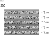
- the electrode 300 is formed by laminating five unit electrodes 310, 320, 330, 340, and 350 in a state of being in close contact with each other, and the unit electrodes adjacent to each other in a laminated state are electrically connected through the electrode mixture.
- the unit electrodes may be bonded to each other by a binder in the electrode mixture in order to prevent a phenomenon in which the unit electrodes push against each other in the laminated state, and a bonding force between the electrode mixture and the unit current collector may be increased due to the presence of the binder.
- a general current collector having no porous structure may be interposed between laminated unit electrodes in various shapes.
- at least one of the general current collectors may be interposed in one electrode, for the general current collector, for example, an aluminum current collector may be used for as a positive electrode, and a copper foil current collector may be used as a negative electrode.
- the unit electrode may be rolled to reduce a thickness of the unit electrode by introducing the electrode mixture into the pores in the current collector, and in this case, a method in which an individual unit electrode is rolled and then laminated may be used, or the unit electrodes may be rolled in a state in which the unit electrode is laminated without individually rolling the unit electrode.
- the present disclosure provides a battery cell having a structure in which at least one of positive and negative electrodes made of the above-described electrode for a secondary battery and an electrolyte are assembled in a cell case, and since the electrolyte may be introduced into open pores of an unit current collector in the electrode for a secondary battery, an electrode mixture introduced into the open pores of the unit current collector may be impregnated into the electrolyte, thereby preventing a capacity from being reduced.
- the present disclosure also provides a method of preparing an electrode for a secondary battery, including:
- the electrode slurry moves into the pores in the unit current collector and thus the inside of the unit current collector may be filled with the electrode slurry. Since the electrode slurry is dried and the unit electrodes are rolled in a state in which the unit current collector is filled with the electrode slurry as described above, the unit electrodes may be formed with a uniform thickness.
- the present disclosure also provides a method of preparing an electrode for a secondary battery, including:
- the electrode slurry moves into the pores in the unit current collector and thus the inside of the unit current collector may be filled with the electrode slurry.
- the electrode slurry is dried in a state in which the unit current collector is filled with the electrode slurry, and the unit electrodes in which the electrode mixture layer is formed are laminated, then the laminated unit electrodes are rolled.
- the present disclosure also provides a lithium secondary battery including the electrode.
- the lithium secondary battery may consist of a positive electrode, a negative electrode, a separator, and a non-aqueous electrolyte containing a lithium salt, and be prepared by inserting a porous separator between the positive electrode and the negative electrode and introducing the electrolyte, which is a conventional method known in the art.
- the electrode according to the present disclosure may be at least one selected from the positive electrode and the negative electrode. That is, both the positive electrode and the negative electrode may have a structure of the electrode according to the present disclosure, or only one of the positive electrode and the negative electrode may have the structure of the electrode according to the present disclosure, and the present disclosure is not particularly limited thereto and may be appropriately selected as necessary.
- the positive electrode for example, may be prepared by coating a unit current collector with a three-dimensional network structure of the present disclosure with a mixture slurry of a positive electrode active material, a conductive material and a binder, and then drying the mixture, a filler may be further added to the mixture as necessary.
- the conductive agent is generally added so that the conductive agent has 1 to 30 wt% based on the total weight of the slurry including the positive electrode active material.
- the conductive agent is not particularly restricted so long as the conductive agent exhibits high conductivity while the conductive agent does not induce any chemical change in a battery to which the conductive agent is applied.
- graphite such as natural graphite or artificial graphite
- carbon black such as carbon black, acetylene black, Ketjen black, channel black, furnace black, lamp black, thermal black
- conductive fiber such as carbon fiber or metallic fiber
- metallic powder such as carbon fluoride powder, aluminum powder, or nickel powder
- conductive whisker such as zinc oxide or potassium titanate
- conductive metal oxide such as titanium oxide
- polyphenylene derivatives may be used as the conductive agent.
- the binder is a component assisting in binding between the active material and conductive agent and in binding with the current collector.
- the binder is generally added in an amount of 1 to 30 wt% based on the total weight of the mixture including the positive electrode active material.
- the binder there may be used polyvinylidene fluoride, polyvinyl alcohol, carboxymethylcellulose (CMC), starch, hydroxypropylcellulose, regenerated cellulose, polyvinyl pyrollidone, tetrafluoroethylene, polyethylene, polypropylene, ethylene-propylene-diene terpolymer (EPDM), sulfonated EPDM, styrene butadiene rubber, fluoro rubber, and various copolymers.
- the negative electrode for example, may be prepared by coating a unit current collector with a three-dimensional network structure of the present disclosure with a mixture slurry of a negative electrode active material, a conductive material and a binder, and then drying the mixture, a filler may be further added to the mixture, as necessary.
- the negative electrode active material for example, there may be used carbon, such as non-graphitizing carbon or a graphite-based carbon; a metal composite oxide, such as Li x Fe 2 O 3 (0 ⁇ x ⁇ 1), Li x WO 2 (0 ⁇ x ⁇ 1), Sn x Me 1-x Me' y O z (Me: Mn, Fe, Pb, Ge; Me': Al, B, P, Si, Group 1, 2 and 3 elements of the periodic table, halogen; 0 ⁇ x ⁇ 1; 1 ⁇ y ⁇ 3; 1 ⁇ z ⁇ 8); lithium metal; lithium alloy; silicon-based alloy; tin-based alloy; a metal oxide, such as SnO, SnO 2 , PbO, PbO 2 , Pb 2 O 3 , Pb 3 O 4 , Sb 2 O 3 , Sb 2 O 4 , Sb 2 O 5 , GeO, GeO 2 , Bi 2 O 3 , Bi 2 O 4 ,
- the positive electrode When the electrode according to the present disclosure is a positive electrode and contains a lithium transition metal oxide generally used as a positive electrode active material, the positive electrode may have a loading amount up to 700 mg/25 cm 2 or more.
- the electrode according to the present disclosure is a negative electrode and contains a carbon material generally used as a negative electrode active material, the negative electrode may have a loading amount up to 300 mg/25 cm 2 or more.
- the separator is disposed between the positive electrode and the negative electrode.
- the separator for example, an insulative thin film exhibiting high ion permeability and high mechanical strength may be used.
- the separator generally has a pore diameter of 0.01 to 10 ⁇ m and a thickness of 5 to 300 ⁇ m.
- a sheet or non-woven fabric made of olefin polymer, such as polypropylene, which exhibits chemical resistance and hydrophobicity, glass fiber, or polyethylene is used.
- a solid electrolyte such as polymer
- the solid electrolyte may function as the separator.
- the non-aqueous electrolyte containing a lithium salt may be composed of a non-aqueous electrolyte and a lithium salt.
- a non-aqueous organic solvent an organic solid electrolyte or an inorganic solid electrolyte may be used, but not limited thereto.
- non-protic organic solvents such as N-methyl-2-pyrollidinone, propylene carbonate, ethylene carbonate, butylene carbonate, dimethyl carbonate, diethyl carbonate, gamma-butyro lactone, 1,2-dimethoxy ethane, tetrahydroxy Franc, 2-methyl tetrahydrofuran, dimethylsulfoxide, 1,3-dioxolane, formamide, dimethylformamide, dioxolane, acetonitrile, nitromethane, methyl formate, methyl acetate, phosphoric acid triester, trimethoxy methane, dioxolane derivatives, sulfolane, methyl sulfolane, 1,3-dimethyl-2-imidazolidinone, propylene carbonate derivatives, tetrahydrofuran derivatives, ether, methyl propionate, and ethyl propionate
- non-protic organic solvents such as N-methyl-2-pyr
- organic solid electrolyte examples include polyethylene derivatives, polyethylene oxide derivatives, polypropylene oxide derivatives, phosphoric acid ester polymers, poly agitation lysine, polyester sulfide, polyvinyl alcohols, polyvinylidene fluoride, and polymers containing ionic dissociation groups.
- lithium Li
- Li lithium
- Li nitrides, halides, and sulphates of lithium (Li), such as Li 3 N, LiI, Li 5 NI 2 , Li 3 N-LiI-LiOH, LiSiO 4 , LiSiO 4 -LiI-LiOH, Li 2 SiS 3 , Li 4 SiO 4 , Li 4 SiO 4 -LiI-LiOH, and Li 3 PO 4 -Li 2 S-SiS 2 .
- Li lithium
- the lithium salt is a material that is readily soluble in the above-mentioned non-aqueous electrolyte, and may include, for example, LiCl, LiBr, LiI, LiClO 4 , LiBF 4 , LiB 10 Cl 10 , LiPF 6 , LiCF 3 SO 3 , LiCF 3 CO 2 , LiAsF 6 , LiSbF 6 , LiAlCl 4 , CH 3 SO 3 Li, CF 3 SO 3 Li, (CF 3 SO 2 ) 2 NLi, chloroborane lithium, lower aliphatic carboxylic acid lithium, lithium tetraphenyl borate, and imide.
- pyridine triethylphosphite, triethanolamine, cyclic ether, ethylenediamine, n-glyme, hexaphosphoric triamide, nitrobenzene derivatives, sulfur, quinone imine dyes, N-substituted oxazolidinone, N,N-substituted imidazolidine, ethylene glycol dialkyl ether, ammonium salts, pyrrole, 2-methoxy ethanol, aluminum trichloride, or the like may be added to the electrolytic solution.
- the non-aqueous electrolytic solution may further include halogen-containing solvents, such as carbon tetrachloride and ethylene trifluoride.
- the non-aqueous electrolytic solution may further include carbon dioxide gas, and may further include fluoro-ethylene carbonate(FEC), propene sultone(PRS), etc.
- a lithium salt such as LiPF 6 , LiClO 4 , LiBF 4 , or LiN(SO 2 CF 3 ) 2 is added to a mixed solvent of a cyclic carbonate such as ethylene carbonate (EC) or propylene carbonate (PC) which is a high-dielectric solvent and a linear carbonate such as diethyl carbonate (DEC), dimethyl carbonate (DMC) or ethylmethyl carbonate (EMC) which is a low-viscosity solvent to prepare a non-aqueous electrolyte containing a lithium salt.
- a cyclic carbonate such as ethylene carbonate (EC) or propylene carbonate (PC) which is a high-dielectric solvent
- a linear carbonate such as diethyl carbonate (DEC), dimethyl carbonate (DMC) or ethylmethyl carbonate (EMC) which is a low-viscosity solvent to prepare a non-aqueous electrolyte containing a lithium
- the present disclosure also provides a secondary battery in which an electrode assembly made of the electrode for a secondary battery is sealed inside a battery case together with an electrolyte.
- the secondary battery may be used for a battery cell which is being used as a power source of a small device.
- the secondary battery may also preferably be used as a unit cell in a battery pack, which include a plurality of battery cells, used as a power source of a middle- or large-sized device in which high temperature stability, long cycle characteristics, high rate characteristics, and the like are required and in a device including the battery pack as a power source.
- the device may be any one selected from a mobile electronics, a power tool powered by battery-based motors; an electric vehicle including an electric vehicle(EV), a hybrid electric vehicle(HEV), a plug-in hybrid electric vehicle(PHEV), etc.; an electric motorcycle including an electric bike(E-bike) and electric scooter(E-scooter); an electric golf cart; power storage systems, but is not limited thereto.
- LiNi 0.55 Mn 0.30 Co 0.15 O 2 as a positive electrode active material, Denka black as a conductive material, and polyvinylidene fluoride as a binder were mixed at a weight ratio of 96:2:2, and N-methyl pyrrolidone (NMP) was added to the mixture to prepare a slurry.
- NMP N-methyl pyrrolidone
- Lithium metal 40 ⁇ m was attached to a copper (Cu) foil as a counter electrode and used, and a polyolefin separator was interposed between the positive electrode and the counter electrode, and then an electrolyte in which 1M lithium hexafluorophosphate (LiPF 6 ) was dissolved in a solvent in which ethylene carbonate (EC) and ethyl methyl carbonate (DEC) were mixed at a volume ratio of 50:50 was injected to prepare a pouch type half-cell.
- LiPF 6 lithium hexafluorophosphate
- EC ethylene carbonate
- DEC ethyl methyl carbonate
- a lithium secondary battery was prepared in the same manner as in Example 1, except that an average diameter of the pores of the current collector was changed as shown in Table 1.
- a lithium secondary battery was prepared in the same manner as in Example 1, except that a thickness of the aluminum felt was changed to 55 ⁇ m, and a thickness of the electrode including the current collector was adjusted to 102 ⁇ m.
- a lithium secondary battery was prepared in the same manner as in Example 5, except that an average diameter of the pores of the current collector was changed as shown in Table 1.
- LiNi 0.55 Mn 0.30 Co 0.15 O 2 as a positive electrode active material, Denka black as a conductive material, and polyvinylidene fluoride as a binder were mixed at a weight ratio of 96:2:2, and N-methyl pyrrolidone (NMP) was added to the mixture to prepare a slurry.
- NMP N-methyl pyrrolidone
- the positive electrode slurry was applied in three layers between two pieces of aluminum and on outer surfaces thereof, followed by drying in a vacuum oven at 120 °C to prepare a positive electrode.
- a thickness of the electrode including the thickness of the current collector was 75 ⁇ m, and a thickness of the current collector was 12 ⁇ m.
- Lithium metal 40 ⁇ m was attached to a copper (Cu) foil as a counter electrode and used, and a polyolefin separator was interposed between the positive electrode and the counter electrode, and then an electrolyte in which 1M lithium hexafluorophosphate (LiPF 6 ) was dissolved in a solvent in which ethylene carbonate (EC) and ethyl methyl carbonate (DEC) were mixed at a volume ratio of 50:50 was injected to prepare a pouch type half-cell.
- LiPF 6 lithium hexafluorophosphate
- EC ethylene carbonate
- DEC ethyl methyl carbonate
- a lithium secondary battery was prepared in the same manner as in Comparative Example 1, except that a thickness of the electrode including the current collector was changed as shown in Table 1.
- the experiment was carried out under the condition of 1/3 C ⁇ 1/3 C (one charge / discharge) between 4.2 V to 2.5 V for the batteries prepared in Examples and Comparative Examples.
- the lifespan characteristics were evaluated from a discharge capacity retention rate, and the discharge capacity retention rate was expressed as a percentage ratio of a capacity after repeating charging and discharging 200 times to an initial capacity. The result is shown in Table 1.
- Example 1 Average Diameter of Pores of Current Collector ( ⁇ m) Thickness of Electrode including Current Collector ( ⁇ m) Lifespan Characteristics Initial Discharge Capacity (mAh/cm 2 ) Capacity After 200 cycles (mAh/cm 2 ) Discharge Capacity Retention Rate at 200 Times (%)
- Example 1 20 75 3.431 3.163 92.2
- Example 2 30 75 3.864 3.578 92.6
- Example 3 50 75 3.715 3.444 92.7
- Example 4 80 75 3.449 3.197 92.7
- Example 5 20 102 3.313 2.932 88.5
- Example 6 30 102 3.753 3.318 88.4
- Example 7 50 102 3.623 3.224 89.0
- Example 8 80 102 3.330 2.957 88.8 Comparative Example 1 - 75 3.643 3.356 92.1 Comparative Example 2 - 102 3.446 2.939 85.3
- the electrodes are high loading electrodes having the same electrode thickness.
- the lifespan characteristics in Examples 5 to 8 were better than those of Comparative Example 2 while the lifespan characteristics of the electrode were significantly lowered in Comparative Example 2.
Landscapes
- Chemical & Material Sciences (AREA)
- Chemical Kinetics & Catalysis (AREA)
- Electrochemistry (AREA)
- General Chemical & Material Sciences (AREA)
- Engineering & Computer Science (AREA)
- Manufacturing & Machinery (AREA)
- Materials Engineering (AREA)
- Battery Electrode And Active Subsutance (AREA)
- Secondary Cells (AREA)
- Cell Electrode Carriers And Collectors (AREA)
Claims (10)
- Elektrode (100) für eine Sekundärbatterie, in welcherzwei oder mehrere Einheitselektroden (10; 201) in einem Zustand eines nahen Kontakts miteinander laminiert sind; undwechselseitig benachbarte Einheitselektroden (10, 201) durch eine Elektrodenmischung (202) elektrisch verbunden sind,wobei, in jeder der Einheitsektroden, die Elektrodenmischung (202), welche ein Elektrodenaktivmaterial beinhaltet, in Poren (203) eines Einheits-Stromkollektors (11) mit einer dreidimensionalen Netzwerkstruktur eingeführt ist,der Einheits-Stromkollektor (11) mit einer dreidimensionalen Netzwerkstruktur ein leitfähiger Metallfilz ist,eine Durchschnittsdicke des Einheits-Stromkollektors (11) mit einer dreidimensionalen Netzwerkstruktur in einem Bereich von 30 µm bis 400 µm ist, undein Durchschnittsdurchmesser von Poren (203) in dem Einheits-Stromkollektor (11) mit einer dreidimensionalen Netzwerkstruktur in einem Bereich von 1 µm bis 100 µm ist.
- Elektrode (100) nach Anspruch 1, wobei die Elektrode eine Struktur aufweist, in welcher 2 bis 10 Einheitselektroden laminiert sind.
- Elektrode (100) nach Anspruch 1, wobei ein Einheits-Stromkollektor (11) mit einer dreidimensionalen Netzwerkstruktur und eine Elektrodenmischung in den Einheitselektroden gemischt sind.
- Elektrode (100) nach Anspruch 1, wobei eine Dicke einer Elektrodenmischungsschicht, welche an einer äußeren Fläche einer Seite des Einheits-Stromkollektors (11) angebracht ist, in einem Bereich von 10 µm bis 100 µm ist.
- Elektrode (100) nach Anspruch 1, wobei eine Dicke der Elektrode in einem Bereich von 50 µm bis 500 µm ist.
- Elektrode nach Anspruch 1, wobei die Einheitselektroden durch ein Bindemittel in einer Elektrodenmischung wechselseitig verbunden sind.
- Batteriezelle, welche aus der Elektrode (100) für eine Sekundärbatterie besteht, wobei eine positive Elektrode, eine negative Elektrode und eine elektrolytische Lösung in einem Zellengehäuse eingebaut sind und wenigstens eine von der positiven Elektrode und der negativen Elektrode nach einem der Ansprüche 1 bis 6 vorbereitet ist.
- Batteriezelle nach Anspruch 7, wobei der Elektrolyt in offene Poren eines Einheits-Stromkollektors (11) in der Elektrode (100) für eine Sekundärbatterie eingeführt ist.
- Verfahren zum Vorbereiten einer Elektrode für eine Sekundärbatterie nach einem der Ansprüche 1 bis 6, umfassend:(a) einen Prozess eines Vorbereitens eines Einheits-Stromkollektors (11) mit einer dreidimensionalen Netzwerkstruktur und einer Elektrodensuspension;(b) einen Prozess eines Bedeckens des Einheits-Stromkollektors (11) mit der Elektrodensuspension;(c) einen Prozess eines Trocknens der Elektrodensuspension, um eine Elektrodenmischungsschicht zu bilden;(d) einen Prozess eines Rollens von Einheitselektroden (10; 201); und(e) einen Prozess eines Laminierens der Einheitselektroden (10; 201).
- Verfahren zum Vorbereiten einer Elektrode (100) für eine Sekundärbatterie nach einem der Ansprüche 1 bis 6, umfassend:(a) einen Prozess eines Vorbereitens eines Einheits-Stromkollektors (11) mit einer dreidimensionalen Netzwerkstruktur und einer Elektrodensuspension;(b) einen Prozess eines Bedeckens des Einheits-Stromkollektors (11) mit der Elektrodensuspension;(c) einen Prozess eines Trocknens der Elektrodensuspension, um eine Elektrodenmischungsschicht zu bilden;(d) einen Prozess eines Laminierens von Einheitselektroden (10; 201); und(e) einen Prozess eines Rollens der laminierten Einheitselektroden (10; 201).
Applications Claiming Priority (3)
| Application Number | Priority Date | Filing Date | Title |
|---|---|---|---|
| KR20160116187 | 2016-09-09 | ||
| KR1020170112505A KR102098154B1 (ko) | 2016-09-09 | 2017-09-04 | 3차원 망상 구조의 전극 집전체를 포함하는 전극 |
| PCT/KR2017/009672 WO2018048166A1 (ko) | 2016-09-09 | 2017-09-05 | 3차원 망상 구조의 전극집전체를 포함하는 전극 |
Publications (3)
| Publication Number | Publication Date |
|---|---|
| EP3370281A1 EP3370281A1 (de) | 2018-09-05 |
| EP3370281A4 EP3370281A4 (de) | 2018-09-05 |
| EP3370281B1 true EP3370281B1 (de) | 2025-04-16 |
Family
ID=61910935
Family Applications (1)
| Application Number | Title | Priority Date | Filing Date |
|---|---|---|---|
| EP17849050.4A Active EP3370281B1 (de) | 2016-09-09 | 2017-09-05 | Elektrode mit elektrodenstromkollektor einer dreidimensionalen netzwerkstruktur |
Country Status (7)
| Country | Link |
|---|---|
| US (1) | US20180337408A1 (de) |
| EP (1) | EP3370281B1 (de) |
| JP (1) | JP6723370B2 (de) |
| KR (1) | KR102098154B1 (de) |
| CN (1) | CN108292736B (de) |
| ES (1) | ES3025283T3 (de) |
| HU (1) | HUE071126T2 (de) |
Families Citing this family (5)
| Publication number | Priority date | Publication date | Assignee | Title |
|---|---|---|---|---|
| JP7426039B2 (ja) * | 2019-08-20 | 2024-02-01 | 国立研究開発法人産業技術総合研究所 | 非水電解質二次電池用の電極、非水電解質二次電池及び非水電解質二次電池用の電極に用いるための集電体 |
| KR102176482B1 (ko) | 2020-08-28 | 2020-11-09 | 한국자동차연구원 | 리튬이차전지 음극용 다공성 입체 집전체의 제조방법 및 그로부터 제조된 입체 집전체를 포함한 음극 |
| KR102397790B1 (ko) | 2020-10-13 | 2022-05-13 | 한국자동차연구원 | 마이크로웨이브를 이용한 고강도 다공성 입체 집전체의 제조방법 및 그로부터 제조된 입체 집전체를 포함한 음극 |
| WO2023177244A1 (ko) * | 2022-03-16 | 2023-09-21 | 주식회사 엘지에너지솔루션 | 이차전지의 건식 전극용 필름 |
| US20240154093A1 (en) * | 2022-11-04 | 2024-05-09 | Lg Energy Solution, Ltd. | Lithium Secondary Battery |
Citations (2)
| Publication number | Priority date | Publication date | Assignee | Title |
|---|---|---|---|---|
| US20110151329A1 (en) * | 2008-08-29 | 2011-06-23 | Saft Group Sa | Lithiated oxide for a positive electrode of an alkaline accumulator |
| US20140306665A1 (en) * | 2011-11-17 | 2014-10-16 | Shine Co., Ltd. | Electrode assembly, method for fabricating same, and battery charging and discharging method |
Family Cites Families (19)
| Publication number | Priority date | Publication date | Assignee | Title |
|---|---|---|---|---|
| JP3738864B2 (ja) * | 1996-11-29 | 2006-01-25 | 株式会社ユアサコーポレーション | アルカリ蓄電池用ニッケル電極 |
| JP2001155739A (ja) * | 1999-11-24 | 2001-06-08 | Nissha Printing Co Ltd | 二次電池用正極および二次電池 |
| JP3849478B2 (ja) * | 2001-09-28 | 2006-11-22 | 松下電器産業株式会社 | アルカリ蓄電池およびその製造方法 |
| KR101276336B1 (ko) * | 2010-05-24 | 2013-06-18 | 주식회사 아모텍 | 다공성 cnf 집전체를 이용한 리튬 이온 커패시터용 전극과 그의 제조방법 및 이를 이용한 리튬 이온 커패시터 |
| KR101088073B1 (ko) * | 2010-10-16 | 2011-12-01 | 주식회사 샤인 | 금속 장섬유를 포함하는 전극 구조를 갖는 전지 및 이의 제조 방법 |
| JP2012160320A (ja) * | 2011-01-31 | 2012-08-23 | Nissan Motor Co Ltd | 電極、電気デバイスおよび電極の製造方法 |
| JP5976551B2 (ja) * | 2011-02-18 | 2016-08-23 | 住友電気工業株式会社 | 三次元網状アルミニウム多孔体及び該アルミニウム多孔体を用いた電極並びに該電極を用いた非水電解質電池、非水電解液を用いたキャパシタ及びリチウムイオンキャパシタ |
| JP2012186142A (ja) * | 2011-02-18 | 2012-09-27 | Sumitomo Electric Ind Ltd | 電気化学デバイス用電極およびその製造方法 |
| KR20120111508A (ko) * | 2011-04-01 | 2012-10-10 | 주식회사 엘지화학 | 이차전지용 전극 집전체 및 이를 포함하는 리튬 이차전지 |
| KR101806547B1 (ko) * | 2011-04-06 | 2018-01-10 | 주식회사 제낙스 | 금속 섬유를 포함하는 전극 구조체를 갖는 전지 및 상기 전극 구조의 제조 방법 |
| DE112013001595T5 (de) * | 2012-03-22 | 2015-01-08 | Sumitomo Electric Industries, Ltd. | Festkörper-Lithiumsekundärbatterie |
| DE112013001587T5 (de) * | 2012-03-22 | 2015-01-08 | Sumitomo Electric Industries, Ltd. | Poröser Metallkörper mit dreidimensionalem Netzwerk für Kollektoren, Elektrode und nicht-wässrige Elektrolyt- Sekundärbatterie |
| KR101746876B1 (ko) * | 2012-05-08 | 2017-06-13 | 삼성에스디아이 주식회사 | 전극판, 이를 포함하는 이차전지 및 전극판의 제조방법 |
| KR101582376B1 (ko) * | 2013-06-07 | 2016-01-04 | 주식회사 제낙스 | 전극, 이의 제조 방법 및 이를 이용한 전지 |
| KR20140147475A (ko) * | 2013-06-20 | 2014-12-30 | 에스케이이노베이션 주식회사 | 그라파이트 펠트를 포함하는 소듐 이차전지 |
| WO2015020338A1 (ko) * | 2013-08-05 | 2015-02-12 | 주식회사 아모그린텍 | 플렉시블 집전체 및 그 제조방법과 이를 이용한 이차전지 |
| KR20150062617A (ko) * | 2013-11-29 | 2015-06-08 | 포스코강판 주식회사 | 워크롤 제조장치 및 이를 이용한 표면처리장치 |
| KR101717220B1 (ko) * | 2014-05-09 | 2017-03-16 | 주식회사 엘지화학 | 둘 이상의 집전체를 구비하는 이차전지용 전극 및 이를 포함하는 리튬 이차전지 |
| KR20160054315A (ko) * | 2014-11-06 | 2016-05-16 | 삼성에스디아이 주식회사 | 리튬 이차 전지용 전극 및 이를 포함하는 리튬 이차 전지 |
-
2017
- 2017-09-04 KR KR1020170112505A patent/KR102098154B1/ko active Active
- 2017-09-05 HU HUE17849050A patent/HUE071126T2/hu unknown
- 2017-09-05 EP EP17849050.4A patent/EP3370281B1/de active Active
- 2017-09-05 ES ES17849050T patent/ES3025283T3/es active Active
- 2017-09-05 JP JP2018547249A patent/JP6723370B2/ja active Active
- 2017-09-05 US US15/774,192 patent/US20180337408A1/en not_active Abandoned
- 2017-09-05 CN CN201780004251.9A patent/CN108292736B/zh active Active
Patent Citations (2)
| Publication number | Priority date | Publication date | Assignee | Title |
|---|---|---|---|---|
| US20110151329A1 (en) * | 2008-08-29 | 2011-06-23 | Saft Group Sa | Lithiated oxide for a positive electrode of an alkaline accumulator |
| US20140306665A1 (en) * | 2011-11-17 | 2014-10-16 | Shine Co., Ltd. | Electrode assembly, method for fabricating same, and battery charging and discharging method |
Also Published As
| Publication number | Publication date |
|---|---|
| ES3025283T3 (en) | 2025-06-06 |
| US20180337408A1 (en) | 2018-11-22 |
| HUE071126T2 (hu) | 2025-08-28 |
| CN108292736B (zh) | 2021-02-26 |
| KR20180028930A (ko) | 2018-03-19 |
| CN108292736A (zh) | 2018-07-17 |
| JP6723370B2 (ja) | 2020-07-15 |
| KR102098154B1 (ko) | 2020-04-08 |
| JP2018535535A (ja) | 2018-11-29 |
| EP3370281A1 (de) | 2018-09-05 |
| EP3370281A4 (de) | 2018-09-05 |
Similar Documents
| Publication | Publication Date | Title |
|---|---|---|
| US10122011B2 (en) | Multi layered electrode and method of manufacturing the same | |
| EP3182487A1 (de) | Elektrode mit mehrschichtiger struktur und lithiumsekundärbatterie damit | |
| US9673444B2 (en) | Method of manufacturing electrode for lithium secondary battery and electrode manufactured using the same | |
| KR101643593B1 (ko) | 전해액 함침성이 향상된 스택-폴딩형 전극조립체 및 이의 제조방법 | |
| KR101717220B1 (ko) | 둘 이상의 집전체를 구비하는 이차전지용 전극 및 이를 포함하는 리튬 이차전지 | |
| KR20130117721A (ko) | 전극 및 이를 포함하는 이차전지 | |
| EP3370281B1 (de) | Elektrode mit elektrodenstromkollektor einer dreidimensionalen netzwerkstruktur | |
| KR102011679B1 (ko) | 양면에 활물질의 로딩량이 상이한 전극판을 포함하는 전극조립체 | |
| KR20130116028A (ko) | 전극의 제조방법 및 이를 사용하여 제조되는 전극 | |
| EP3654415B1 (de) | Elektrode ohne stromkollektor und sekundärbatterie damit | |
| KR20130117711A (ko) | 성능이 우수한 리튬 이차전지 | |
| US20130302668A1 (en) | Electrolyte for secondary battery and the secondary battery comprising the same | |
| KR102082467B1 (ko) | 집전체 중심 부위에 높은 활물질 로딩량을 가지는 전극을 포함하는 전극조립체 | |
| KR102026292B1 (ko) | 활물질 로딩량의 구배를 가진 전극을 포함하는 전극조립체 | |
| KR101744120B1 (ko) | 침상 관통 테스트 안전성이 향상된 파우치형 이차전지 | |
| KR20130117356A (ko) | 양극 활물질 및 이를 포함하는 이차전지 | |
| KR101506451B1 (ko) | 이차전지용 음극 | |
| KR102070907B1 (ko) | 충방전 시 발생하는 가스를 수용할 수 있는 잉여부를 포함하는 전지셀 | |
| KR20130117712A (ko) | 성능이 우수한 리튬 이차전지 | |
| US9831493B2 (en) | Cathode active material and lithium secondary battery comprising the same | |
| KR101514303B1 (ko) | 전극의 제조방법 및 이를 사용하여 제조되는 전극 | |
| US20130273427A1 (en) | Secondary battery having improved safety | |
| US20210336253A1 (en) | Anode Active Material And The Secondary Battery Comprising The Same | |
| KR101666413B1 (ko) | 하이브리드 스택-폴딩형 전극조립체 및 이를 포함하는 이차전지 | |
| KR101666415B1 (ko) | 하이브리드 스택-폴딩형 전극조립체 및 이를 포함하는 이차전지 |
Legal Events
| Date | Code | Title | Description |
|---|---|---|---|
| STAA | Information on the status of an ep patent application or granted ep patent |
Free format text: STATUS: THE INTERNATIONAL PUBLICATION HAS BEEN MADE |
|
| PUAI | Public reference made under article 153(3) epc to a published international application that has entered the european phase |
Free format text: ORIGINAL CODE: 0009012 |
|
| STAA | Information on the status of an ep patent application or granted ep patent |
Free format text: STATUS: REQUEST FOR EXAMINATION WAS MADE |
|
| 17P | Request for examination filed |
Effective date: 20180529 |
|
| A4 | Supplementary search report drawn up and despatched |
Effective date: 20180731 |
|
| AK | Designated contracting states |
Kind code of ref document: A1 Designated state(s): AL AT BE BG CH CY CZ DE DK EE ES FI FR GB GR HR HU IE IS IT LI LT LU LV MC MK MT NL NO PL PT RO RS SE SI SK SM TR |
|
| AX | Request for extension of the european patent |
Extension state: BA ME |
|
| DAV | Request for validation of the european patent (deleted) | ||
| DAX | Request for extension of the european patent (deleted) | ||
| RAP1 | Party data changed (applicant data changed or rights of an application transferred) |
Owner name: LG ENERGY SOLUTION LTD. |
|
| RAP3 | Party data changed (applicant data changed or rights of an application transferred) |
Owner name: LG ENERGY SOLUTION, LTD. |
|
| STAA | Information on the status of an ep patent application or granted ep patent |
Free format text: STATUS: EXAMINATION IS IN PROGRESS |
|
| 17Q | First examination report despatched |
Effective date: 20220628 |
|
| GRAP | Despatch of communication of intention to grant a patent |
Free format text: ORIGINAL CODE: EPIDOSNIGR1 |
|
| STAA | Information on the status of an ep patent application or granted ep patent |
Free format text: STATUS: GRANT OF PATENT IS INTENDED |
|
| RIC1 | Information provided on ipc code assigned before grant |
Ipc: H01M 4/02 20060101ALI20241212BHEP Ipc: H01M 4/80 20060101ALI20241212BHEP Ipc: H01M 4/66 20060101ALI20241212BHEP Ipc: H01M 10/0525 20100101ALI20241212BHEP Ipc: H01M 4/04 20060101ALI20241212BHEP Ipc: H01M 4/139 20100101ALI20241212BHEP Ipc: H01M 4/74 20060101ALI20241212BHEP Ipc: H01M 4/13 20100101AFI20241212BHEP |
|
| INTG | Intention to grant announced |
Effective date: 20250102 |
|
| P01 | Opt-out of the competence of the unified patent court (upc) registered |
Free format text: CASE NUMBER: APP_572/2025 Effective date: 20250107 |
|
| GRAS | Grant fee paid |
Free format text: ORIGINAL CODE: EPIDOSNIGR3 |
|
| GRAA | (expected) grant |
Free format text: ORIGINAL CODE: 0009210 |
|
| STAA | Information on the status of an ep patent application or granted ep patent |
Free format text: STATUS: THE PATENT HAS BEEN GRANTED |
|
| AK | Designated contracting states |
Kind code of ref document: B1 Designated state(s): AL AT BE BG CH CY CZ DE DK EE ES FI FR GB GR HR HU IE IS IT LI LT LU LV MC MK MT NL NO PL PT RO RS SE SI SK SM TR |
|
| REG | Reference to a national code |
Ref country code: GB Ref legal event code: FG4D |
|
| REG | Reference to a national code |
Ref country code: CH Ref legal event code: EP Ref country code: DE Ref legal event code: R096 Ref document number: 602017088972 Country of ref document: DE |
|
| REG | Reference to a national code |
Ref country code: IE Ref legal event code: FG4D |
|
| REG | Reference to a national code |
Ref country code: ES Ref legal event code: FG2A Ref document number: 3025283 Country of ref document: ES Kind code of ref document: T3 Effective date: 20250606 |
|
| REG | Reference to a national code |
Ref country code: NL Ref legal event code: MP Effective date: 20250416 |
|
| REG | Reference to a national code |
Ref country code: HU Ref legal event code: AG4A Ref document number: E071126 Country of ref document: HU |
|
| PG25 | Lapsed in a contracting state [announced via postgrant information from national office to epo] |
Ref country code: NL Free format text: LAPSE BECAUSE OF FAILURE TO SUBMIT A TRANSLATION OF THE DESCRIPTION OR TO PAY THE FEE WITHIN THE PRESCRIBED TIME-LIMIT Effective date: 20250416 |
|
| REG | Reference to a national code |
Ref country code: AT Ref legal event code: MK05 Ref document number: 1786408 Country of ref document: AT Kind code of ref document: T Effective date: 20250416 |
|
| PG25 | Lapsed in a contracting state [announced via postgrant information from national office to epo] |
Ref country code: FI Free format text: LAPSE BECAUSE OF FAILURE TO SUBMIT A TRANSLATION OF THE DESCRIPTION OR TO PAY THE FEE WITHIN THE PRESCRIBED TIME-LIMIT Effective date: 20250416 Ref country code: PT Free format text: LAPSE BECAUSE OF FAILURE TO SUBMIT A TRANSLATION OF THE DESCRIPTION OR TO PAY THE FEE WITHIN THE PRESCRIBED TIME-LIMIT Effective date: 20250818 |
|
| PGFP | Annual fee paid to national office [announced via postgrant information from national office to epo] |
Ref country code: DE Payment date: 20250820 Year of fee payment: 9 |
|
| REG | Reference to a national code |
Ref country code: LT Ref legal event code: MG9D |
|
| PG25 | Lapsed in a contracting state [announced via postgrant information from national office to epo] |
Ref country code: GR Free format text: LAPSE BECAUSE OF FAILURE TO SUBMIT A TRANSLATION OF THE DESCRIPTION OR TO PAY THE FEE WITHIN THE PRESCRIBED TIME-LIMIT Effective date: 20250717 Ref country code: NO Free format text: LAPSE BECAUSE OF FAILURE TO SUBMIT A TRANSLATION OF THE DESCRIPTION OR TO PAY THE FEE WITHIN THE PRESCRIBED TIME-LIMIT Effective date: 20250716 |
|
| PG25 | Lapsed in a contracting state [announced via postgrant information from national office to epo] |
Ref country code: PL Free format text: LAPSE BECAUSE OF FAILURE TO SUBMIT A TRANSLATION OF THE DESCRIPTION OR TO PAY THE FEE WITHIN THE PRESCRIBED TIME-LIMIT Effective date: 20250416 |
|
| PG25 | Lapsed in a contracting state [announced via postgrant information from national office to epo] |
Ref country code: BG Free format text: LAPSE BECAUSE OF FAILURE TO SUBMIT A TRANSLATION OF THE DESCRIPTION OR TO PAY THE FEE WITHIN THE PRESCRIBED TIME-LIMIT Effective date: 20250416 |
|
| PGFP | Annual fee paid to national office [announced via postgrant information from national office to epo] |
Ref country code: BE Payment date: 20250820 Year of fee payment: 9 Ref country code: HU Payment date: 20250929 Year of fee payment: 9 Ref country code: GB Payment date: 20250820 Year of fee payment: 9 |
|
| PG25 | Lapsed in a contracting state [announced via postgrant information from national office to epo] |
Ref country code: HR Free format text: LAPSE BECAUSE OF FAILURE TO SUBMIT A TRANSLATION OF THE DESCRIPTION OR TO PAY THE FEE WITHIN THE PRESCRIBED TIME-LIMIT Effective date: 20250416 |
|
| PG25 | Lapsed in a contracting state [announced via postgrant information from national office to epo] |
Ref country code: AT Free format text: LAPSE BECAUSE OF FAILURE TO SUBMIT A TRANSLATION OF THE DESCRIPTION OR TO PAY THE FEE WITHIN THE PRESCRIBED TIME-LIMIT Effective date: 20250416 |
|
| PGFP | Annual fee paid to national office [announced via postgrant information from national office to epo] |
Ref country code: FR Payment date: 20250821 Year of fee payment: 9 |
|
| PG25 | Lapsed in a contracting state [announced via postgrant information from national office to epo] |
Ref country code: RS Free format text: LAPSE BECAUSE OF FAILURE TO SUBMIT A TRANSLATION OF THE DESCRIPTION OR TO PAY THE FEE WITHIN THE PRESCRIBED TIME-LIMIT Effective date: 20250716 |
|
| PG25 | Lapsed in a contracting state [announced via postgrant information from national office to epo] |
Ref country code: IS Free format text: LAPSE BECAUSE OF FAILURE TO SUBMIT A TRANSLATION OF THE DESCRIPTION OR TO PAY THE FEE WITHIN THE PRESCRIBED TIME-LIMIT Effective date: 20250816 |
|
| PG25 | Lapsed in a contracting state [announced via postgrant information from national office to epo] |
Ref country code: LV Free format text: LAPSE BECAUSE OF FAILURE TO SUBMIT A TRANSLATION OF THE DESCRIPTION OR TO PAY THE FEE WITHIN THE PRESCRIBED TIME-LIMIT Effective date: 20250416 |