EP3337676B1 - Flachprägedruckmaschine und prägeplatte - Google Patents
Flachprägedruckmaschine und prägeplatte Download PDFInfo
- Publication number
- EP3337676B1 EP3337676B1 EP16758084.4A EP16758084A EP3337676B1 EP 3337676 B1 EP3337676 B1 EP 3337676B1 EP 16758084 A EP16758084 A EP 16758084A EP 3337676 B1 EP3337676 B1 EP 3337676B1
- Authority
- EP
- European Patent Office
- Prior art keywords
- tool
- plate
- base plate
- tool plate
- embossing
- Prior art date
- Legal status (The legal status is an assumption and is not a legal conclusion. Google has not performed a legal analysis and makes no representation as to the accuracy of the status listed.)
- Active
Links
- 238000004049 embossing Methods 0.000 title claims description 111
- 238000010438 heat treatment Methods 0.000 claims description 99
- 239000000463 material Substances 0.000 claims description 34
- 230000006698 induction Effects 0.000 claims description 19
- 230000005291 magnetic effect Effects 0.000 claims description 18
- 239000012876 carrier material Substances 0.000 claims description 11
- 230000007246 mechanism Effects 0.000 claims description 11
- 230000001939 inductive effect Effects 0.000 claims description 9
- 230000005293 ferrimagnetic effect Effects 0.000 claims description 7
- 239000004020 conductor Substances 0.000 claims description 5
- 239000003302 ferromagnetic material Substances 0.000 claims description 5
- 229920002430 Fibre-reinforced plastic Polymers 0.000 claims description 4
- 239000011151 fibre-reinforced plastic Substances 0.000 claims description 4
- 238000007639 printing Methods 0.000 description 45
- 238000000034 method Methods 0.000 description 32
- 230000008569 process Effects 0.000 description 32
- 239000011888 foil Substances 0.000 description 17
- 238000011161 development Methods 0.000 description 15
- 230000018109 developmental process Effects 0.000 description 15
- 239000004033 plastic Substances 0.000 description 8
- 229920003023 plastic Polymers 0.000 description 8
- 229910052751 metal Inorganic materials 0.000 description 6
- 239000002184 metal Substances 0.000 description 6
- 230000006835 compression Effects 0.000 description 4
- 238000007906 compression Methods 0.000 description 4
- 230000001105 regulatory effect Effects 0.000 description 4
- 229910052782 aluminium Inorganic materials 0.000 description 3
- XAGFODPZIPBFFR-UHFFFAOYSA-N aluminium Chemical compound [Al] XAGFODPZIPBFFR-UHFFFAOYSA-N 0.000 description 3
- 239000000835 fiber Substances 0.000 description 3
- 238000004519 manufacturing process Methods 0.000 description 3
- 238000003825 pressing Methods 0.000 description 3
- 238000012546 transfer Methods 0.000 description 3
- 230000008901 benefit Effects 0.000 description 2
- 230000033228 biological regulation Effects 0.000 description 2
- 230000008859 change Effects 0.000 description 2
- 238000006243 chemical reaction Methods 0.000 description 2
- 239000002131 composite material Substances 0.000 description 2
- 238000013461 design Methods 0.000 description 2
- 229920006351 engineering plastic Polymers 0.000 description 2
- 239000004744 fabric Substances 0.000 description 2
- 239000011159 matrix material Substances 0.000 description 2
- 238000005259 measurement Methods 0.000 description 2
- 239000012811 non-conductive material Substances 0.000 description 2
- 239000012783 reinforcing fiber Substances 0.000 description 2
- 239000004753 textile Substances 0.000 description 2
- 229910001369 Brass Inorganic materials 0.000 description 1
- RYGMFSIKBFXOCR-UHFFFAOYSA-N Copper Chemical compound [Cu] RYGMFSIKBFXOCR-UHFFFAOYSA-N 0.000 description 1
- 229910001141 Ductile iron Inorganic materials 0.000 description 1
- 239000004593 Epoxy Substances 0.000 description 1
- FYYHWMGAXLPEAU-UHFFFAOYSA-N Magnesium Chemical compound [Mg] FYYHWMGAXLPEAU-UHFFFAOYSA-N 0.000 description 1
- 239000004642 Polyimide Substances 0.000 description 1
- 229910000831 Steel Inorganic materials 0.000 description 1
- 230000009471 action Effects 0.000 description 1
- 239000000853 adhesive Substances 0.000 description 1
- 230000001070 adhesive effect Effects 0.000 description 1
- 239000010951 brass Substances 0.000 description 1
- 239000011111 cardboard Substances 0.000 description 1
- 229920006026 co-polymeric resin Polymers 0.000 description 1
- 238000010276 construction Methods 0.000 description 1
- 230000001276 controlling effect Effects 0.000 description 1
- 229910052802 copper Inorganic materials 0.000 description 1
- 239000010949 copper Substances 0.000 description 1
- 230000001419 dependent effect Effects 0.000 description 1
- 238000005553 drilling Methods 0.000 description 1
- 230000000694 effects Effects 0.000 description 1
- 238000005265 energy consumption Methods 0.000 description 1
- 239000011152 fibreglass Substances 0.000 description 1
- 239000011521 glass Substances 0.000 description 1
- 239000003365 glass fiber Substances 0.000 description 1
- 230000003993 interaction Effects 0.000 description 1
- 238000002372 labelling Methods 0.000 description 1
- 239000011777 magnesium Substances 0.000 description 1
- 229910052749 magnesium Inorganic materials 0.000 description 1
- 150000002739 metals Chemical class 0.000 description 1
- 238000003801 milling Methods 0.000 description 1
- 239000000123 paper Substances 0.000 description 1
- 229920000647 polyepoxide Polymers 0.000 description 1
- 229920001225 polyester resin Polymers 0.000 description 1
- 229920001721 polyimide Polymers 0.000 description 1
- 238000004382 potting Methods 0.000 description 1
- 230000035484 reaction time Effects 0.000 description 1
- 229920005989 resin Polymers 0.000 description 1
- 239000011347 resin Substances 0.000 description 1
- 230000000284 resting effect Effects 0.000 description 1
- 238000010008 shearing Methods 0.000 description 1
- 229920002050 silicone resin Polymers 0.000 description 1
- 238000009751 slip forming Methods 0.000 description 1
- 238000005476 soldering Methods 0.000 description 1
- 239000010959 steel Substances 0.000 description 1
- 239000012815 thermoplastic material Substances 0.000 description 1
- 229920001187 thermosetting polymer Polymers 0.000 description 1
- 230000007704 transition Effects 0.000 description 1
- 238000003466 welding Methods 0.000 description 1
- 238000004804 winding Methods 0.000 description 1
- 229910000859 α-Fe Inorganic materials 0.000 description 1
Images

Classifications
-
- B—PERFORMING OPERATIONS; TRANSPORTING
- B44—DECORATIVE ARTS
- B44B—MACHINES, APPARATUS OR TOOLS FOR ARTISTIC WORK, e.g. FOR SCULPTURING, GUILLOCHING, CARVING, BRANDING, INLAYING
- B44B5/00—Machines or apparatus for embossing decorations or marks, e.g. embossing coins
- B44B5/02—Dies; Accessories
- B44B5/028—Heated dies
-
- B—PERFORMING OPERATIONS; TRANSPORTING
- B21—MECHANICAL METAL-WORKING WITHOUT ESSENTIALLY REMOVING MATERIAL; PUNCHING METAL
- B21D—WORKING OR PROCESSING OF SHEET METAL OR METAL TUBES, RODS OR PROFILES WITHOUT ESSENTIALLY REMOVING MATERIAL; PUNCHING METAL
- B21D22/00—Shaping without cutting, by stamping, spinning, or deep-drawing
- B21D22/02—Stamping using rigid devices or tools
-
- B—PERFORMING OPERATIONS; TRANSPORTING
- B21—MECHANICAL METAL-WORKING WITHOUT ESSENTIALLY REMOVING MATERIAL; PUNCHING METAL
- B21D—WORKING OR PROCESSING OF SHEET METAL OR METAL TUBES, RODS OR PROFILES WITHOUT ESSENTIALLY REMOVING MATERIAL; PUNCHING METAL
- B21D37/00—Tools as parts of machines covered by this subclass
- B21D37/16—Heating or cooling
-
- B—PERFORMING OPERATIONS; TRANSPORTING
- B41—PRINTING; LINING MACHINES; TYPEWRITERS; STAMPS
- B41F—PRINTING MACHINES OR PRESSES
- B41F19/00—Apparatus or machines for carrying out printing operations combined with other operations
- B41F19/02—Apparatus or machines for carrying out printing operations combined with other operations with embossing
- B41F19/06—Printing and embossing between a negative and a positive forme after inking and wiping the negative forme; Printing from an ink band treated with colour or "gold"
- B41F19/064—Presses of the reciprocating type
-
- B—PERFORMING OPERATIONS; TRANSPORTING
- B41—PRINTING; LINING MACHINES; TYPEWRITERS; STAMPS
- B41F—PRINTING MACHINES OR PRESSES
- B41F33/00—Indicating, counting, warning, control or safety devices
-
- H—ELECTRICITY
- H05—ELECTRIC TECHNIQUES NOT OTHERWISE PROVIDED FOR
- H05B—ELECTRIC HEATING; ELECTRIC LIGHT SOURCES NOT OTHERWISE PROVIDED FOR; CIRCUIT ARRANGEMENTS FOR ELECTRIC LIGHT SOURCES, IN GENERAL
- H05B6/00—Heating by electric, magnetic or electromagnetic fields
- H05B6/02—Induction heating
- H05B6/10—Induction heating apparatus, other than furnaces, for specific applications
- H05B6/14—Tools, e.g. nozzles, rollers, calenders
-
- B—PERFORMING OPERATIONS; TRANSPORTING
- B41—PRINTING; LINING MACHINES; TYPEWRITERS; STAMPS
- B41P—INDEXING SCHEME RELATING TO PRINTING, LINING MACHINES, TYPEWRITERS, AND TO STAMPS
- B41P2219/00—Printing presses using a heated printing foil
- B41P2219/30—Printing dies
- B41P2219/31—Heating means
Definitions
- the invention relates to the field of flat stamping printing machines and relates to a flat stamping printing machine and a tool plate for a flat stamping printing machine according to the preamble of claims 1 and 15.
- Embossing printing machines are used, among other things, for embossing foil printing, hologram transfer, blind embossing, microembossing and structure embossing.
- stamping foil In the case of foil stamping, a stamping foil is "pressed" onto a flat material with the aid of an embossing tool and, as a rule, under the action of heat.
- the transferred film lies in one plane with the flat material.
- the flat material is the carrier of the embossing or printing embossing.
- Flat embossing printing machines represent a special type of construction of embossing printing machines and differ from other embossing printing machines, among other things, by a flat bed press with press head and press table.
- the press head which receives the tool plate, corresponds to the upper part of the press. It represents the counterpart to the press table, the lower part of the press, which holds the counter pressure plate.
- Flat stamping printing machines are characterized by a high stamping performance and stamping quality. This is why flat stamping printing machines are also suitable for particularly demanding stamping tasks, such as the production of banknotes.
- Flat embossing printing machines allow, in particular, precise positioning of the flat material in the embossing zone and the use of highly sensitive embossing foils.
- Flat embossing printing machines are also characterized by optimal operating conditions, such as uniform temperature and pressure conditions in the area of the embossing zone.
- Typical flat stamping printing machines are, for example, from EP 0858 888 and the WO 2009/14644 known.
- the publication font EP 2 664 458 A2 describes a device for printing a workpiece made of glass with a hot stamping foil using an embossing stamp.
- at least part of the stamping die is inductively heated during or immediately before the hot foil stamping.
- the publication font U.S. 2,558,354 describes a device for labeling and embossing cylindrical bodies with an embossing device which can be inductively heated.
- the publication font GB 867 287 describes a device for transferring a pattern made of thermoplastic material onto an object made of plastic.
- the pattern is arranged on a carrier in the form of a metal strip. By heating the carrier, the pattern is softened so that it can be transferred to the object by means of a pressing process.
- the carrier can be heated inductively.
- the embossing tools are brought to an operating temperature, e.g. B. to 150 to 200 ° C, heated.
- the operating temperature is designed, for example, so that an embossing foil with a plastic transfer layer is activated, in particular melted, by the heat of the embossing tool during the embossing process in order to create a material connection with the flat material.
- embossing For error-free embossing and in order to achieve the highest embossing quality, it is important, on the one hand, to heat the embossing tools to the optimum operating temperature and to keep them at this temperature while the machine is in operation. On the other hand, it is also important that the operating temperature is the same across all embossing tools and that it can be kept the same during operation of the machine. This is the only way to guarantee the same embossing conditions over the entire tool plate, so that there are no quality differences in the embossed flat material.
- the heating process is not only of great importance in terms of setting the optimum operating temperature of the stamping tools.
- the heated machine parts also expand. This thermal expansion must be taken into account in advance when setting the embossing geometries. This is the only way to achieve precise embossing. Consequently, it is extremely important that the machine is operated at the optimum operating temperature to which the embossing geometry has been set in advance.
- the components of the press head which are also heated up unintentionally, are, however, also subject to thermal expansion, which in turn influences the stamping accuracy. Therefore, the embossing process can only be started, albeit the press head is heated to a stable operating temperature. This is taken into account in advance in the embossing settings.
- the flat stamping printing machine should also be suitable for demanding stamping tasks and should not show any loss in the quality of the stamped products compared to conventional flat stamping printing machines.
- Another object of the present invention is to propose a flat stamping printing machine with a heating device, which is characterized by lower energy costs.
- Another object of the present invention is to propose a flat stamping printing machine with a heating device, which is characterized by precise, instantaneous regulation of the tool temperature.
- the heating device or the temperature control is intended, in particular, to make it easier to heat the stamping tools to an operating temperature that is the same for all of the stamping tools and to maintain this operating temperature.
- a further object of the present invention is to propose a flat embossing printing machine with a heating device, by means of which the embossing tools can be heated as precisely as possible without further machine parts being unnecessarily heated.
- Tool plate with stamping tool and the base plate are in particular part of a press head.
- the back of the base plate faces the press head.
- the base plate is attached to the press head in particular via the back of the plate.
- the press head is in particular arranged above a press table, also called an embossing table, which comprises a counter-pressure plate.
- a flat material and an embossing film web are introduced between the tool plate and the counter pressure plate, which are spaced apart from one another.
- the embossing pressure is carried out by bringing together the tool plate with the embossing tool and the counter pressure plate while applying pressure.
- the counter-pressure plate is moved towards the stationary tool plate during the stamping process.
- the press pressure is consequently exerted by the counter pressure plate or press table on the tool plate or the press head.
- the press pressure is transferred from the die plate to the rest of the press head via the base plate.
- the tool plate is fastened to the press head in a detachable manner, in particular via a holder.
- the tool plate is released from the press head and z. B. moved via a guide device into a set-up position in which the tool plate can be equipped with embossing tools.
- the tool plate is moved back into its operating position via the guide device and fastened to the press head by means of a bracket.
- the base plate remains, in particular, stationary on the press head.
- the base plate can, however, also be releasably attached to the press head.
- the heater is now an induction heater with an inductor.
- an alternating magnetic field is generated by means of an inductor through which alternating current flows, which produces eddy currents and possibly also magnetic reversal losses in an electrically conductive body to be heated induced, which cause the body to warm up.
- the inductor is therefore an inductive heating means.
- the inductor is designed and arranged between the tool plate side and the base plate rear side that an alternating magnetic field extending beyond the base plate on the tool plate side can be generated for inductive heating of an inductively heatable tool plate on the other side of the tool plate side and outside the base plate.
- the alternating magnetic field extends into the tool plate in particular.
- the induction heating device contains, in particular, a device for providing alternating current at the required frequency.
- the device can in particular comprise a power unit, e.g. with a frequency converter, which provides the electrical power at the required frequency.
- the heat is generated directly in the body to be heated and consequently does not have to be transferred to it by conduction. Accordingly, the heat output can be easily controlled and the efficiency is very high, especially with ferromagnetic materials.
- the induction heating device is now designed to inductively heat the tool plate, with an alternating magnetic field being applied in a targeted manner in the tool plate by means of an inductor.
- the embossing tools are heated up indirectly via the tool plate through thermal conduction.
- the induction heating device can also be designed to additionally inductively heat the stamping tools mounted on the tool plate.
- the alternating magnetic field is also applied to the embossing tools by means of an inductor.
- the induction heating device can inductively heat both the stamping tools and the tool plate, possibly with different degrees of efficiency.
- the stamping tools can be made of different materials such as brass, steel, magnesium or aluminum, depending on the area of application, i.e. depending on the materials to be stamped and depending on the prevailing stamping pressures and stamping temperatures. Some of these metals do not have particularly good inductive properties, so that the embossing tools are comparatively poor, i.e. particularly with poor efficiency, or cannot be heated inductively at all.
- the tool plate can also be viewed as part of the induction heating device.
- inductive heating also has the advantage that the inductive effect can take place through non-conductive materials, such as plastic, without the non-conductive materials being inductively heated. So between the inductor and the heating zone, in which inductive heating will be arranged, non-conductive body, which does not affect the heating process.
- the tool plate in cooperation with an alternating magnetic field, forms a heating zone made of an inductively heatable material.
- the heating zone in the tool plate consists in particular of or contains a ferromagnetic material.
- the entire tool plate can also consist of or contain a ferromagnetic material.
- the tool plate can in particular consist of nodular cast iron, in particular GGG40.
- the tool plate typically has a width transverse to the process direction of 70 to 110 cm and a length in the process direction of 50 to 80 cm.
- the height or thickness of the tool plate is typically 15 to 20 mm.
- the tool plate is in particular formed in one piece.
- the tool plate forms a continuous, i.e. continuous base area in the area of the rear side of the tool plate.
- the height of the floor area can e.g. B. from 1 to 5 mm, in particular from 1 to 3 mm.
- Continuous or continuous means that the floor area runs uninterrupted over the entire surface of the tool plate, i.e. has no openings.
- the heating zone formed in the tool plate includes in particular the continuous floor area. Thanks to the continuous floor area, the thermal energy generated inductively in the floor area is distributed quickly and evenly across the floor.
- the induction heating device is designed accordingly in such a way that the alternating magnetic field is directed into the tool plate and, in particular, into its base area.
- the eddy currents generated in the mold plate ensure that it is heated quickly and evenly.
- the tool plate contains a plurality of depressions which are open towards the tool side and are detached from the continuous bottom area towards the rear side of the plate.
- the recesses are not continuously formed between the tool side and the back of the plate but are delimited by the bottom area. The depressions run transversely to the support surfaces formed by the tool side and the back of the plate.
- the depressions serve as a fastening aid for the embossing tools which are detachably fastened on the tool side. They consequently form a fastening zone in the tool plate.
- the depressions can be made in the tool plate by means of drilling or milling.
- the depressions are designed in particular as bores in the tool plate.
- the depressions are in particular blind holes.
- the tool plate is constructed in several parts and z.
- B. comprises a carrier plate with continuous holes and a base plate resting on its rear side.
- the floor slab forms the continuous floor area.
- the base plate is made of or contains a ferromagnetic material.
- the base plate can be connected to the carrier plate via a material connection such as soldering or welding.
- a mechanical connection is also conceivable.
- a special embodiment of such a tool plate is the honeycomb foundation known in the prior art.
- the present one differs Tool plate from the known honeycomb foundation in that the depressions in the tool plate are not designed as continuous holes from the tool side to the rear of the plate, but rather are closed off towards the rear of the plate and end in the transition to the continuous floor area.
- the inductor is designed in particular as a coiled electrical conductor. Its curvatures are in particular arranged in a plane parallel to the support surface which is formed on the tool plate side.
- the inductor can in particular be a flat coil, such as a spiral flat coil.
- the base plate forms a flat support surface on the tool plate side. With the exception of an opening for a temperature sensor, the support surface is in particular continuous.
- the base plate forms a flat support surface on its back.
- the support surface is not designed to be continuous.
- the support surface can in particular be interrupted by depressions or recesses for receiving the inductor or field guide elements.
- the aforementioned embossing pressures are transmitted between the tool plate and the rest of the press head via the aforementioned contact surfaces.
- the base plate accommodates the inductor.
- Recessed means in particular that the inductor does not extend beyond the support surface on the rear side.
- the base plate and inductor are thus part of a heating module.
- the inductor can, for example, be embedded in depressions or recesses in the base plate.
- the depressions or recesses can, for. B. be slot-shaped.
- the depressions or recesses are open towards the rear of the base plate.
- the base plate has, in particular, a floor area towards the tool plate side.
- the depressions or recesses for the inductor are delimited towards the tool plate side, in particular by the base area.
- the floor area is in particular continuous.
- the inductor can, for example, be cast or glued into the depressions or recesses of the base plate.
- the inductor it is also possible for the inductor to be integrated into the base plate during the manufacture of the base plate.
- the inductor is enclosed on all sides by the carrier material of the base plate.
- the tool side and the rear side both have a continuous support surface, possibly with the exception of an opening for a temperature sensor.
- field guide elements with ferrimagnetic properties are arranged between the inductor and the rear side of the base plate.
- the field guide elements serve to deflect and, if necessary, also to modulate the magnetic alternating field. This is to ensure that the alternating magnetic field on the one hand is optimally directed into the die plate and on the other hand, if possible, does not penetrate the rest of the press head. With this measure, undesired heating of the rest of the press head can be prevented or at least reduced.
- the field guide elements can, for. B. be ferrite body.
- the base plate accommodates the field guiding elements.
- Recessed means in particular that the field guide elements do not extend beyond the support surface of the back of the plate.
- the field guiding elements can be part of the heating module mentioned above.
- the field guide elements can, for example, be embedded in depressions or recesses in the base plate. As discussed above as an alternative variant, the field guide elements can also be integrated into the base plate together with the inductor during the manufacture of the base plate.
- a flat shielding element with at least one layer made of an electrically conductive material is arranged on the back of the base plate.
- the shielding element covers the contact surface of the back of the base plate over an area, in particular over the entire area. In particular, the shielding element rests against the support surface.
- the shielding element cannot be heated inductively or only slightly. In this way, the shielding element shields the rest of the press head in the rear area of the base plate at least partially from the alternating magnetic field, without the shielding element itself being heated to any significant degree. This measure helps to prevent or at least reduce heating of the rest of the press head.
- the shielding element is in particular made of a metal with very good electrical conductivity, such as aluminum or copper, or contains this.
- the shielding element can in particular be designed as a plate or sheet metal.
- the base plate consists in particular of a carrier material which is not electrically conductive.
- the carrier material of the base plate is designed in particular to be thermally insulating. In this way, the thermal energy generated in the tool plate cannot penetrate into the rest of the press head by means of heat conduction through the base plate via the base plate rear side.
- the base plate therefore thermally insulates the press head arranged above from the die plate arranged below.
- the carrier material is also characterized in particular by its dimensional stability, mechanical strength, in particular compressive strength, and temperature resistance.
- Compressive strength means that the base plate can absorb compression pressures that occur during stamping or can transfer them between the tool plate and the rest of the press head without being structurally damaged, in particular deformed.
- the carrier material can, for example, be resistant to pressures of up to 600 N / mm 2 and can be used accordingly.
- the carrier material can, for example, be resistant to temperatures of up to 250 ° C. and can be used accordingly.
- the carrier material is preferably a plastic, in particular an engineering plastic or contains such a z. B. in the form of a matrix.
- the carrier material can in particular be a fiber-reinforced plastic.
- the reinforcing fibers are in particular glass fibers.
- the engineering plastic mentioned is characterized in particular by its high application temperatures and high compressive strengths.
- the fibers of the fiber-reinforced plastic can be in the form of flat textile structures, such as fiber mats.
- the textile fabrics can in particular be short fiber mats or fine or roving fabrics.
- the plastic which forms the matrix in the presence of reinforcing fibers is in particular a z. B. be based on a resin system thermoset.
- the plastic can in particular be made of an epoxy, polyester, copolymer, polyimide or silicone resin or contain this.
- the base plate lies particularly flat on the tool plate via its tool side. Furthermore, the base plate lies particularly flat on the rest of the press head via its plate rear side. In this way, pressing forces can be transmitted between the base plate and the tool plate or between the base plate and the press head via the mutually facing support surfaces.
- the mutually facing support surfaces of the base plate and tool plate or of the base plate and the press head are in particular plane-parallel to one another during operation. All four bearing surfaces preferably run plane-parallel to one another.
- the base plate can have a height or thickness of 10 to 30 mm.
- the tolerance range with regard to the thickness of the base plate is in particular only 0.02 to 0.05 mm.
- the base plate can have a width of 10 to 30 cm and a length of 20 to 50 cm.
- the flat stamping printing machine contains a plurality of side by side over the back of the tool plate arranged heating modules, each with at least one base plate and one inductor.
- the individual heating modules can be controlled individually and can consequently be operated individually. This allows individual areas of the tool plate to be heated individually.
- the heating zone of the tool plate can thus be divided into individual sub-zones (sub-heating zones), which can be heated individually.
- a blown air stream is z. B. in sheet-fed machines on the output side and in endless web machines on the input and output sides of the embossing area for separating the film web from the flat material.
- the process direction here means the direction in which the flat material is transported during operation through the embossing area between the embossing tool and the counter-pressure plate.
- the front or rear area can now be supplied with more heating power than the middle area.
- the flat stamping printing machine contains, in particular, several heating modules arranged one behind the other in the process direction.
- the flat stamping printing machine can also contain several heating modules arranged next to one another in the process direction. However, it is also possible that the heating modules, in relation to the process direction, extend over the entire transverse extent of the tool plate.
- the flat stamping printing machine contains both a plurality of heating modules arranged one behind the other and a plurality of heating modules arranged next to one another in the process direction.
- each heating module comprises a device for detecting the temperature in the corresponding sub-zone, in particular a temperature measuring device with at least one temperature sensor, as described below.
- a separate power unit can be assigned to each inductor of a heating module.
- the inductors of the heating modules are individually supplied with power via a common power unit by means of a multiplexer.
- the heating device contains a device for determining or recording at least one temperature of the tool plate, in particular a temperature in the heating zone of the tool plate.
- the device can be part of the heating module.
- the temperature is, based on the surface area of the tool plate, in particular at least at one point or in at least one area of the Tool plate determined.
- the device can in particular also be designed to determine the temperature at several points or areas of the tool plate.
- the heating zone comprises a continuous base area of the tool plate, then in particular a temperature of the base area is determined or measured.
- the above-mentioned device is a temperature measuring device with at least one temperature sensor for measuring a temperature of the tool plate, in particular of the base area.
- the temperature sensor can, for. B. be a Pt100 sensor.
- the temperature sensor is attached in particular to a sensor carrier.
- the sensor carrier is embedded in a recess in the base plate.
- the recess has an opening towards the tool plate side.
- the temperature measuring device is designed in such a way that the temperature sensor forms a measuring contact with the tool plate, in particular with the base area, during operation.
- the temperature measuring device can contain a movement mechanism via which the temperature sensor is movably attached to the base plate relative to the base plate.
- the movement mechanism is designed so that the temperature sensor by means of the movement mechanism at least between a measuring position, in which the temperature sensor forms a measuring contact with the tool plate in the operating position, and a set-up position different from the measuring position, which the temperature sensor during (change) the Tool plate occupies, is movable.
- the measuring position is designed in such a way that the temperature sensor makes physical measuring contact with the tool plate in the operating position.
- the temperature sensor is aligned, in particular, flush with the support surface of the tool plate side in the measuring position or protrudes from it.
- the movement mechanism can contain a restoring element which is designed to move the temperature sensor into one of the two positions, in particular into the set-up position, by means of a restoring force when an adjusting force acting directly or indirectly on the temperature sensor is no longer applicable.
- thermo measuring device as described, for example, on the basis of the exemplary embodiment Figures 8a and 8b is shown, the set-up position is now designed so that the temperature sensor is arranged in the base plate at a distance from the support surface of the tool plate side. This means that the temperature sensor is retracted into the base plate.
- the temperature sensor can be moved via the movement mechanism towards the tool plate side into the measuring position and from there back into the set-up position.
- the movement mechanism can have a drive.
- the drive can, for. B. be done pneumatically or hydraulically.
- the drive moves the temperature sensor z. B. by means of a pneumatically or hydraulically exerted adjusting force by means of a guide from the set-up position to the measuring position.
- the movement mechanism can also contain a restoring element, such as a restoring spring (tension spring), which ensures that the temperature sensor is returned from the measuring position to the set-up position by the restoring force of the restoring element when the adjusting force is lowered or removed.
- a restoring element such as a restoring spring (tension spring)
- the set-up position is designed so that the temperature sensor protrudes from the support surface on the tool plate side. This means that the temperature sensor protrudes from the base plate.
- the temperature sensor can be moved into the measuring position via the movement mechanism towards the support surface and can be moved from the measuring position away from the base plate into the set-up position.
- the determination of the temperature on the tool plate is used in particular to regulate the temperature of the tool plate.
- the flat stamping printing machine contains, in particular, a device for regulating the temperature of the tool plate based on temperature values which are recorded by the device for determining the temperature.
- the heating power of the induction heating device is determined by the control device.
- the flat stamping printing machine also has, in particular, a film web guide for guiding the film web through the stamping area between the stamping tool and the counter pressure plate.
- the stamping foil can be a metal foil, a plastic foil or a composite foil.
- the stamping foil can be a picture or color foil.
- the flat stamping printing machine has, in particular, a transport device for the flat material.
- the transport device contains a feed device for feeding the flat material into the embossing area between the embossing tool and counter-pressure plate and a removal device for moving the flat material away from the embossing area after the embossing has taken place.
- the flat material is particularly flexible.
- the flat material is z. B. made of paper, cardboard, plastic, metal or a composite thereof.
- the flat material can be supplied in the form of individual sheets (sheet-fed machine) or in the form of a continuous web (continuous web machine).
- the present invention has the advantage that the reduced setting and retooling times, thanks to the shorter heating-up time, lead to a higher productivity of the flat stamping printing machine. In this way, the heating time can be reduced to less than an hour with the flat stamping printing machine according to the invention.
- the induction heating device is also characterized by a greatly reduced energy consumption, since the thermal energy can be generated directly in the body to be heated and there is no unnecessary heating of other machine parts.
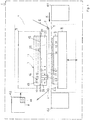
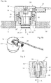
- the Figure 1 shows a schematic representation of a flat stamping printing machine 1.
- the machine 1 contains a flat bed press 4 with an embossing table 8 and a press head 7.
- the embossing table 8 comprises a counter pressure plate 9.
- a base plate 10 with an induction heating device 3 is arranged on the press head 7.
- the base plate 10 has a plate rear side 11 with a first support surface and a tool plate side 12 opposite the plate rear side 11 with a second support surface.
- the base plate 10 rests flat against a fastening component of the press head 7 with the support surface of the rear side 11 of the plate and is mechanically connected to it.
- the press head 7 further comprises a tool plate 20. This forms a plate rear side 35 with a first support surface and a tool side 36 opposite the plate rear side 35 with a tool receiving surface (see also FIG Figure 2 ).
- the tool plate 20 rests with the contact surface of the rear side 35 of the plate against the contact surface of the tool plate side 12 of the base plate 10.
- the tool plate 20 is releasably attached to the press head 7.
- Embossing tools 23 are detachably attached to the tool side 36 of the tool plate 20.
- the tool plate 20 is designed as a honeycomb foundation and contains a honeycomb region 22 for fastening the embossing tools, which forms a fastening zone with a plurality of blind holes 31 running transversely to the support surface.
- a feed device 41 for the flat material 5 and a removal device 42 for the flat material 5 are also shown schematically.
- the flat stamping printing machine 1 is designed as a sheet-fed machine
- the flat material 5 is present as a sheet 5.1.
- the feed device 41 comprises a feeder and the removal device 42 comprises a boom.
- the flat stamping printing machine 1 is designed as an endless web machine
- the flat material 5 is present as an endless web 5.2.
- the feed device 41 comprises an unwinding unit and the removal device 42 comprises a winding unit.
- the flat stamping printing machine 1 further comprises a film web guide 2 for guiding a stamping film web 6 through the stamping area between the tool plate 20 and the counter pressure plate 9.
- the flat stamping printing machine 1 further comprises a machine control 43 for controlling the flat bed press 4 as well as the film web guide 2 and the feed and removal device 41, 42.
- the heating device 3 further comprises a regulating device 44 for regulating the temperature of the tool plate 20.
- the regulating device 44 is integrated into the machine control 43 here.
- the embossing foil and flat material 5 are inserted and positioned between the tool plate 20 and the counter pressure plate 9. While the flat material 5 is being introduced in the process direction X, the embossing foil can also be introduced in the process direction X or against the process direction X.
- the flat material 5 rests on the counter-pressure plate 9.
- the stamping foil 6 is arranged between the flat material 5 and the tool plate 20.
- the embossing table 8 By moving up (see arrows) the embossing table 8, the counter-pressure plate 9 is pressed against the stationary tool plate 20 while applying an embossing pressure. After completion of the embossing process, the embossing table 8 with the counter-pressure plate 9 is moved downwards again. The embossing table 8 thus carries out an embossing stroke H. The embossed flat material 5 is then moved on in the process direction X.
- a compressed air device 40 for generating a blown air flow for the purpose of separating the embossed flat material 5 from the film web 6 is arranged on the exit side of the embossing area in the process direction X (see FIG Figure 3 , 6 and 7 ).
- the compressed air device 40 is z. B. a fan.
- the embossing tools 23 must first be heated to an embossing temperature.
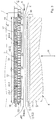
- the base plate 10 is part of an induction heating device 3.
- An inductor 16 in the form of a flat coil (see also FIG Figure 4 ) is embedded in the base plate 10 and arranged between the tool plate side 12 and the rear side 11 of the plate.
- the inductor 16 is inserted from the plate rear 11 into slot openings 33 in the base plate 10 and in this z. B. glued with an adhesive or potted with a potting material.
- the slot openings 33 are correspondingly open towards the rear side 11 of the plate.
- the flat coil 16 is arranged plane-parallel to the support surface on the tool plate side 12.
- the Figure 5a shows a plan view of the base plate 10 towards the rear side 11 of the plate.
- the back side of the plate 11 shows, among other things, the slot openings 33 for the flat coil 16 and a through opening 34 for the sensor unit 26, which will be described further below.
- the carrier material 13 of the base plate 10 is a glass fiber reinforced plastic and is accordingly not electrically conductive, but permeable to the generated alternating magnetic field 19.
- the inductor 16 is fed with an alternating current in order to put the induction heating device 3 into operation.
- the design and arrangement of the inductor 16 now generates an alternating magnetic field 19 which penetrates into the base area 21 of the tool plate 20 and heats it inductively.
- ferrimagnetic bodies 18 are arranged in the base plate 10 between the support surface of the rear side 11 of the plate and the inductor 16. The ferrimagnetic bodies 18 are let into recesses in the base plate 10 from the rear side 11 of the plate. The ferrimagnetic bodies 18 are used to deflect the alternating magnetic field towards the die plate 20 and thus also to shield the rest of the press head 7 on the plate rear 11.
- the Figure 5b shows the top view of a heating module looking towards the rear side 11 of the base plate 10.
- the heating module comprises the flat coil 16 inserted into the slot openings 33 of the base plate and the above-mentioned ferrimagnetic bodies 18, which are also located in depressions in the base plate 10 between the flat coil 16 and the Support surface of the plate back 11 are arranged.
- the rear side 11 of the base plate 10 is a shielding element 17 in the form of an aluminum sheet with a thickness of, for. B. 0.2 mm at ( Figure 2 ).
- the shielding element 17 serves to shield the rest of the press head 7 from the alternating magnetic field. This is intended to prevent inductive heating of the rest of the press head 7.
- the shielding element 17 can also be part of the heating module.
- the thermal energy inductively generated in the base area 21 of the tool plate 20 is now conducted by means of heat conduction to the tool side 36 and from there into the embossing tools 23.
- the heat conduction within the continuous base area 21, parallel to the support surface of the rear side of the plate ensures a homogeneous temperature over the entire extent of the tool plate 20.
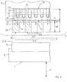
- the Figure 6 shows a particular embodiment of an induction heating device for a continuous web machine with four heating modules, each with a base plate 10.1 to 10.4 and an inductor.
- the four heating modules are arranged one behind the other on the rear side of the tool plate 20 in the process direction X.
- the tool plate 20 is in Figure 6 for the sake of completeness still drawn in dotted lines.
- the tool plate 20 has a length L in the process direction X and a width B transverse to the process direction X.
- a compressed air device 40 for generating a blown air flow, which is arranged on the inlet and outlet side, is also shown.
- the Figure 7 shows an embodiment for a sheet-fed machine with a total of six heating modules 10.1 to 10.6.
- heating modules 10.3 to 10.6 are arranged next to one another at right angles to the process direction X.
- two further heating modules 10.3 to 10.6 are arranged next to one another at right angles to the process direction X.
- blown air is blown in on the output side and optionally also on the input side of the embossing area by means of a compressed air device 40, the input-side or output-side subzone cools down faster than the central subzones of the heating zone.
- each heating module has a temperature sensor 25.1 to 25.4 ( Figure 6 ) or 25.1 to 25.6 ( Figure 7 ), with which the temperature in the corresponding sub-zone is measured.
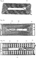
- the Figure 3 shows a schematic cross-sectional view through the embossing area of an embossing printing machine with a tool plate 20 and two heating modules arranged next to one another on the back of the plate 35, each with a base plate 10.1, 10.2.
- the heating modules can be operated individually, so that, viewed in the process direction X, a front and a rear partial zone of the heating zone formed by the base area 21 can be heated independently of one another.
- the respective heating module contains a temperature measuring device with a temperature sensor 25.1, 25.2 (see also Figures 8a, 8b ).
- the Figures 8a and 8b show a first embodiment of a temperature measuring device 24 with a sensor unit 26.
- the sensor unit 26 comprises a temperature sensor 25 which is attached to the end of a movable sensor carrier 30 and is directed towards the support surface of the base plate 10.
- the sensor carrier 30 is in the form of a sleeve and forms the movable part of the sensor unit 26.
- the sensor unit 26 further comprises a housing 32 in which the sensor carrier 30 together with the temperature sensor 25 is displaceably guided along a movement axis A between a measuring position S1 and a set-up position S2 via a sliding guide.
- a tension spring 27 acts as a restoring element, which returns the sensor carrier 30 together with the temperature sensor 25 to the set-up position S2 or holds it in it.
- the above-mentioned elements together form a movement mechanism for displacing the sensor carrier 30 with the temperature sensor 25.
- the sensor unit 26 is let into a through opening 34 in the base plate 10, the temperature sensor 25 being directed towards the tool plate side 12.
- the movement mechanism is driven by a pneumatic drive 28.
- a gas pressure is thus built up in the cavity of the sensor carrier 30 via a pneumatic line. If the compressive force exerted on the sleeve by the gas pressure exceeds the restoring force of the tension spring 27, the sensor carrier 30 is moved from the set-up position S2 into the measuring position S1.
- the control of the pneumatic drive 28 and thus the position of the temperature sensor takes place, for. B. via the machine control 43.
- a sensor line 59 is provided, which is led from the temperature sensor 25 through the cavity of the sensor carrier 30 to the outside.
- the temperature measuring device described above is particularly suitable for flat stamping printing machines in which the tool plate is brought up to the base plate with a lateral movement component during assembly after (re) setting up, so that the tool plate has a protruding temperature sensor during assembly, e.g. B. by shearing, could damage.
- the second embodiment shown of a temperature measuring device differs from the first embodiment according to FIGS Figures 8a and 8b in that it does not contain any pneumatic device for the controlled movement of the sensor carrier in the base plate.
- the temperature measuring device 54 contains a sensor unit 56.
- the sensor unit 56 comprises a temperature sensor 55 which is attached to the end of a movable sensor carrier 60 and is directed towards the support surface on the tool plate side of the base plate.
- the sensor carrier 60 is in the form of a sleeve and forms the movable part of the sensor unit 56.
- the sensor unit 56 further comprises a housing 62 in which the movable sensor carrier 60 with the temperature sensor 55 is movably guided along a movement axis A via a sliding guide.
- the sensor unit 56 is let into a through opening in the base plate, the temperature sensor 55 being directed towards the tool plate side.
- the sliding guide is formed by a guide sleeve 61 which is fixedly arranged in the housing 62.
- the movable sensor carrier 60 forms a particular one for this purpose cylindrical sliding section, over which the sensor carrier 60 is slidably guided along an in particular cylindrical sliding section of the sliding sleeve 61.
- the sliding sections are in particular circular cylindrical. The sliding section of the movable sensor carrier 60 engages over the sliding section of the sliding sleeve 61 or - as in FIG Figure 9 shown - intervenes in this.
- the sliding sections of the two sleeves 60, 61 are surrounded by a compression spring 57 in the form of a helical spring.
- a compression spring 57 in the form of a helical spring.
- One end of the compression spring 57 rests against a stop on the sensor carrier 60 and the other end rests against a stop on the guide sleeve 61.
- the compression spring 57 serves as a restoring element which moves the pressure-relieved sensor carrier 60 together with the temperature sensor 55 into the set-up position and holds it in this position.
- the end portion of the sensor sleeve 60 with the temperature sensor 55 protrudes in the set-up position, for. B. by around 0.5 mm, beyond the contact surface of the base plate (see Figure 9 ).
- the temperature measuring device described above is particularly suitable for flat stamping printing machines in which the tool plate is brought up to the base plate perpendicular to the support surface of the base plate during assembly after the (re) set-up, so that the tool plate cannot damage a protruding temperature sensor during assembly, but rather rather it pushes it back into the base plate. In this way, sufficient contact pressure of the temperature sensor on the tool plate in the operating position is guaranteed for the purpose of forming the measuring contact.
- a sensor line 59 is also provided, which is led from the temperature sensor 55 through the cavity of the sensor carrier 60 and the sliding guide 61 to the outside.
Landscapes
- Engineering & Computer Science (AREA)
- Mechanical Engineering (AREA)
- Physics & Mathematics (AREA)
- Electromagnetism (AREA)
- Shaping Of Tube Ends By Bending Or Straightening (AREA)
- Press Drives And Press Lines (AREA)
- Machines For Manufacturing Corrugated Board In Mechanical Paper-Making Processes (AREA)
- Moulds For Moulding Plastics Or The Like (AREA)
- Printing Methods (AREA)
Applications Claiming Priority (2)
| Application Number | Priority Date | Filing Date | Title |
|---|---|---|---|
| CH01211/15A CH711441A1 (de) | 2015-08-21 | 2015-08-21 | Flachprägedruckmaschine. |
| PCT/CH2016/000108 WO2017031603A2 (de) | 2015-08-21 | 2016-08-15 | Flachprägedruckmaschine |
Publications (2)
| Publication Number | Publication Date |
|---|---|
| EP3337676A2 EP3337676A2 (de) | 2018-06-27 |
| EP3337676B1 true EP3337676B1 (de) | 2021-12-22 |
Family
ID=54207261
Family Applications (1)
| Application Number | Title | Priority Date | Filing Date |
|---|---|---|---|
| EP16758084.4A Active EP3337676B1 (de) | 2015-08-21 | 2016-08-15 | Flachprägedruckmaschine und prägeplatte |
Country Status (6)
| Country | Link |
|---|---|
| US (1) | US11117416B2 (ja) |
| EP (1) | EP3337676B1 (ja) |
| JP (1) | JP6899377B2 (ja) |
| CN (1) | CN108136815B (ja) |
| CH (1) | CH711441A1 (ja) |
| WO (1) | WO2017031603A2 (ja) |
Families Citing this family (9)
| Publication number | Priority date | Publication date | Assignee | Title |
|---|---|---|---|---|
| CN107107608B (zh) * | 2014-12-04 | 2019-07-05 | 吉茨公司 | 包括箔条引导装置和单张引导装置的平面烫印机 |
| CH711441A1 (de) * | 2015-08-21 | 2017-02-28 | Gietz Ag | Flachprägedruckmaschine. |
| US9913994B2 (en) * | 2016-02-26 | 2018-03-13 | Steve Marchese | LED therapy bed |
| KR102052702B1 (ko) | 2017-06-26 | 2019-12-05 | 엘지전자 주식회사 | 코일 어셈블리 및 유도 가열 장치 |
| CN108045087B (zh) * | 2018-02-07 | 2024-02-27 | 江苏劲嘉新型包装材料有限公司 | 检品剔废烫金机 |
| CN110228288B (zh) * | 2018-03-05 | 2022-09-16 | 博斯特(上海)有限公司 | 吹气装置单元以及烫金模切设备 |
| US20230129474A1 (en) * | 2020-04-10 | 2023-04-27 | Korber Tissue S.p.A. | Method and device for heating an embossing roller in an embossing-laminating device |
| CN112319037B (zh) * | 2020-11-26 | 2024-04-19 | 浙江星淦科技有限公司 | 一种可更换凹凸版模板装置 |
| CN113232414B (zh) * | 2021-05-12 | 2023-10-13 | 泸州裕同包装科技有限公司 | 一种用于防伪印刷技术的烫印设备及烫印方法 |
Family Cites Families (31)
| Publication number | Priority date | Publication date | Assignee | Title |
|---|---|---|---|---|
| US1909844A (en) * | 1931-12-15 | 1933-05-16 | Brenner Louis | Printing machine |
| US2558354A (en) * | 1947-12-13 | 1951-06-26 | Ira S Gottscho | Hot die marking device |
| US2740352A (en) * | 1953-09-04 | 1956-04-03 | Lewis A Kingsley | Type head adapter for hot stamping machines |
| GB867287A (en) * | 1959-03-07 | 1961-05-03 | Athos Forti | Improvements in or relating to apparatus for the transference of designs |
| US3486449A (en) * | 1966-08-26 | 1969-12-30 | Alfred B Levine | Process of repulsion printing employing a radiant energy field |
| DE2724886C3 (de) | 1976-08-31 | 1980-08-07 | Maschinenfabrik Gietz Ag, Gossau (Schweiz) | Verfahren und Vorrichtung zum Herstellen von schalenartigen Werkstücken |
| CH674337A5 (ja) | 1987-04-08 | 1990-05-31 | Gietz Ag Maschf | |
| DE4241210C2 (de) * | 1992-12-08 | 1996-02-08 | Joachim Utsch | Anlage zum Prägen einer Legende auf vorgefertigte Schilderplatinen und Einfärben der geprägten Schilder, insbesondere zur Herstellung von Kraftfahrzeug-Kennzeichenschildern |
| EP0708046A1 (de) | 1994-10-21 | 1996-04-24 | Maschinenfabrik Gietz Ag | Registereinzugsvorrichtung |
| EP0741001B1 (de) | 1995-05-04 | 2002-02-06 | Gietz AG | Präge-Druck- und Stanzmaschine |
| DE59805462D1 (de) | 1997-02-13 | 2002-10-17 | Gietz Ag Gossau Maschf | Flach-Prägedruckmaschine |
| US6814830B2 (en) * | 2000-10-26 | 2004-11-09 | Sankyo Seiki Mfg. Co., Ltd. | Hot-stamping foil tape cassette and foil-peeling mechanism for hot-stamping device and peeling method for hot-stamping foil a control method for hot-stamping foil tape cassette |
| WO2005075184A1 (ja) * | 2004-02-04 | 2005-08-18 | Sumitomo Heavy Industries, Ltd. | 加圧成形装置、金型及び加圧成形方法 |
| JP3974118B2 (ja) | 2004-04-22 | 2007-09-12 | 株式会社名機製作所 | 光学製品の転写成形装置および転写成形方法 |
| EP1593503B1 (de) | 2004-05-04 | 2013-06-26 | Maschinenfabrik Gietz Ag | Folienbahnführung für eine Flachprägedruckmaschine |
| JP4244207B2 (ja) * | 2004-07-23 | 2009-03-25 | 株式会社日立産機システム | 緩衝層付押圧転写用金型及び押圧転写方法 |
| JP2006256078A (ja) * | 2005-03-17 | 2006-09-28 | Ricoh Co Ltd | プレス成形装置、このプレス成形装置を用いたプレス成形方法およびこのプレス成形装置により形成された樹脂成形品 |
| US20070056451A1 (en) * | 2005-09-15 | 2007-03-15 | Klann Kenneth J | Composite printing die |
| US7388178B2 (en) | 2006-05-01 | 2008-06-17 | Energy Conversion Devices, Inc. | Rapid thermal response induction heating system for platen embossing |
| US8196307B2 (en) | 2006-09-03 | 2012-06-12 | Gietz Ag | Register insertion apparatus |
| CN200957690Y (zh) * | 2006-10-11 | 2007-10-10 | 苏州大学 | 塑料印刷机 |
| GB0620955D0 (en) * | 2006-10-20 | 2006-11-29 | Speakman Stuart P | Methods and apparatus for the manufacture of microstructures |
| KR101432849B1 (ko) * | 2006-10-31 | 2014-08-26 | 오와이 모디네스 리미티드 | 복합 3차원 형태를 갖는 광학 제품을 제조하기 위한 방법 및 장치 |
| US8025632B2 (en) | 2007-07-20 | 2011-09-27 | össur hf. | Wearable device having feedback characteristics |
| WO2009143644A1 (de) * | 2008-05-27 | 2009-12-03 | Gietz Ag | Flachprägedruckmaschine mit einer folienbahnführungseinrichtung |
| CN202242388U (zh) * | 2011-09-29 | 2012-05-30 | 上海绿新包装材料科技股份有限公司 | 电磁感应加热模压装置 |
| DE102012009773A1 (de) * | 2012-05-16 | 2013-11-21 | Heinz-Glas Group Holding HGGH GmbH & Co. KGaA | Verfahren und Vorrichtung zum Bedrucken eines Werkstücks aus Glas mit einer Heißprägefolie unter Verwendung eines Prägestempels |
| CN202764567U (zh) * | 2012-08-14 | 2013-03-06 | 无锡光群雷射科技有限公司 | 一种电磁加热版辊雷射压印机 |
| JP5376038B1 (ja) | 2012-11-05 | 2013-12-25 | オムロン株式会社 | 転写成形装置 |
| JP6300327B2 (ja) * | 2012-12-27 | 2018-03-28 | テーセェーテク スウェーデン アクチエボラグTCTech Sweden AB | 金型または工具を加熱するための装置および方法 |
| CH711441A1 (de) * | 2015-08-21 | 2017-02-28 | Gietz Ag | Flachprägedruckmaschine. |
-
2015
- 2015-08-21 CH CH01211/15A patent/CH711441A1/de not_active Application Discontinuation
-
2016
- 2016-08-15 US US15/752,267 patent/US11117416B2/en active Active
- 2016-08-15 CN CN201680056161.XA patent/CN108136815B/zh active Active
- 2016-08-15 EP EP16758084.4A patent/EP3337676B1/de active Active
- 2016-08-15 JP JP2018509776A patent/JP6899377B2/ja active Active
- 2016-08-15 WO PCT/CH2016/000108 patent/WO2017031603A2/de active Application Filing
Also Published As
| Publication number | Publication date |
|---|---|
| EP3337676A2 (de) | 2018-06-27 |
| CN108136815B (zh) | 2020-05-22 |
| JP6899377B2 (ja) | 2021-07-07 |
| CH711441A1 (de) | 2017-02-28 |
| WO2017031603A2 (de) | 2017-03-02 |
| CN108136815A (zh) | 2018-06-08 |
| US20180229543A1 (en) | 2018-08-16 |
| JP2018527223A (ja) | 2018-09-20 |
| US11117416B2 (en) | 2021-09-14 |
| WO2017031603A3 (de) | 2017-04-27 |
Similar Documents
| Publication | Publication Date | Title |
|---|---|---|
| EP3337676B1 (de) | Flachprägedruckmaschine und prägeplatte | |
| EP0292738B1 (de) | Doppelbandpresse mit erwärm- oder kühlbaren Teilen und Verfahren zu deren Herstellung | |
| EP1892078B1 (de) | Verfahren und Vorrichtung zum Vorformen von Kohlenstofffaser-Halbzeugen für die Herstellung von Faserverbundbauteilen | |
| WO2007019961A1 (de) | Verfahren zum verbinden des stoss von dichtungsprofilen sowie vorrichtung zu dessen durchführung | |
| EP2039460A2 (de) | Verlegevorrichtung, Kontaktiervorrichtung, Zustellsystem, Verlege- und Kontaktiereinheit, herstellungsanlage, Verfahren zur Herstellung und eine Transpondereinheit | |
| DE3210551A1 (de) | Verfahren und vorrichtung zum anbringen eines praegefolien-abdruckes auf einer flexiblen materialbahn | |
| EP2673138B1 (de) | Verfahren und vorrichtung zum stanz-laminieren einer ersten folie auf eine folienbahn | |
| DE102015010000B4 (de) | Werkzeugvorrichtung zur Fertigung von Bauteilen sowie Verfahren zur Fertigung der Werkzeugvorrichtung | |
| EP3595878A1 (de) | Verfahren und anlage zum konsolidieren von faserverbundstrukturen | |
| EP0812262B1 (de) | Verfahren zum herstellen von wellpappe | |
| DE102010032147B4 (de) | Verfahren und Vorrichtung zum Betrieb einer Schneidvorrichtung an einer Stickmaschine | |
| DE102017105343A1 (de) | Verfahren und Vorrichtung zum Konsolidieren von Faserverbundstrukturen | |
| EP0140117B1 (de) | Kontinuierlich arbeitende Presse zum Pressen einer vorlaufenden Werkstoffbahn | |
| EP0244035B1 (de) | Verfahren und Vorrichtung zum Aufbringen von Markierungslinien auf eine bindemittelhaltige Mineralfaserbahn | |
| DE102012009773A1 (de) | Verfahren und Vorrichtung zum Bedrucken eines Werkstücks aus Glas mit einer Heißprägefolie unter Verwendung eines Prägestempels | |
| DE102014203559B4 (de) | Verfahren und Vorrichtung zum Herstellen einer stoffschlüssigen Verbindung | |
| DE102013101124B4 (de) | Vorrichtung und Verfahren zum Sintern eines Sinterproduktes | |
| WO2012045647A1 (de) | Verfahren und ofen zum behandeln von werkstücken | |
| EP0392047A1 (de) | Verfahren und Vorrichtung zum Heissverformen einer Kunstharz-Schichtpressstoffplatte | |
| DE102007062755B4 (de) | Heizpresse | |
| DE102007055274B4 (de) | Laminator | |
| DE10218560B4 (de) | Verfahren zum Herstellen eines harzgebundenen Formteils | |
| DE102010028545A1 (de) | Anschlagloser Folientransfer | |
| DE4420196C1 (de) | Einrichtung zum Vorheizen von Einzelblättern in einem elektrografischen Druck- oder Kopiergerät | |
| DE102016108467B3 (de) | Werkzeugvorrichtung |
Legal Events
| Date | Code | Title | Description |
|---|---|---|---|
| STAA | Information on the status of an ep patent application or granted ep patent |
Free format text: STATUS: THE INTERNATIONAL PUBLICATION HAS BEEN MADE |
|
| PUAI | Public reference made under article 153(3) epc to a published international application that has entered the european phase |
Free format text: ORIGINAL CODE: 0009012 |
|
| STAA | Information on the status of an ep patent application or granted ep patent |
Free format text: STATUS: REQUEST FOR EXAMINATION WAS MADE |
|
| 17P | Request for examination filed |
Effective date: 20180213 |
|
| AK | Designated contracting states |
Kind code of ref document: A2 Designated state(s): AL AT BE BG CH CY CZ DE DK EE ES FI FR GB GR HR HU IE IS IT LI LT LU LV MC MK MT NL NO PL PT RO RS SE SI SK SM TR |
|
| AX | Request for extension of the european patent |
Extension state: BA ME |
|
| DAV | Request for validation of the european patent (deleted) | ||
| DAX | Request for extension of the european patent (deleted) | ||
| GRAP | Despatch of communication of intention to grant a patent |
Free format text: ORIGINAL CODE: EPIDOSNIGR1 |
|
| STAA | Information on the status of an ep patent application or granted ep patent |
Free format text: STATUS: GRANT OF PATENT IS INTENDED |
|
| INTG | Intention to grant announced |
Effective date: 20210812 |
|
| GRAS | Grant fee paid |
Free format text: ORIGINAL CODE: EPIDOSNIGR3 |
|
| GRAA | (expected) grant |
Free format text: ORIGINAL CODE: 0009210 |
|
| STAA | Information on the status of an ep patent application or granted ep patent |
Free format text: STATUS: THE PATENT HAS BEEN GRANTED |
|
| AK | Designated contracting states |
Kind code of ref document: B1 Designated state(s): AL AT BE BG CH CY CZ DE DK EE ES FI FR GB GR HR HU IE IS IT LI LT LU LV MC MK MT NL NO PL PT RO RS SE SI SK SM TR |
|
| REG | Reference to a national code |
Ref country code: GB Ref legal event code: FG4D Free format text: NOT ENGLISH |
|
| REG | Reference to a national code |
Ref country code: CH Ref legal event code: EP |
|
| REG | Reference to a national code |
Ref country code: DE Ref legal event code: R096 Ref document number: 502016014297 Country of ref document: DE |
|
| REG | Reference to a national code |
Ref country code: AT Ref legal event code: REF Ref document number: 1456841 Country of ref document: AT Kind code of ref document: T Effective date: 20220115 |
|
| REG | Reference to a national code |
Ref country code: IE Ref legal event code: FG4D Free format text: LANGUAGE OF EP DOCUMENT: GERMAN |
|
| REG | Reference to a national code |
Ref country code: LT Ref legal event code: MG9D |
|
| PG25 | Lapsed in a contracting state [announced via postgrant information from national office to epo] |
Ref country code: RS Free format text: LAPSE BECAUSE OF FAILURE TO SUBMIT A TRANSLATION OF THE DESCRIPTION OR TO PAY THE FEE WITHIN THE PRESCRIBED TIME-LIMIT Effective date: 20211222 Ref country code: LT Free format text: LAPSE BECAUSE OF FAILURE TO SUBMIT A TRANSLATION OF THE DESCRIPTION OR TO PAY THE FEE WITHIN THE PRESCRIBED TIME-LIMIT Effective date: 20211222 Ref country code: FI Free format text: LAPSE BECAUSE OF FAILURE TO SUBMIT A TRANSLATION OF THE DESCRIPTION OR TO PAY THE FEE WITHIN THE PRESCRIBED TIME-LIMIT Effective date: 20211222 Ref country code: BG Free format text: LAPSE BECAUSE OF FAILURE TO SUBMIT A TRANSLATION OF THE DESCRIPTION OR TO PAY THE FEE WITHIN THE PRESCRIBED TIME-LIMIT Effective date: 20220322 |
|
| REG | Reference to a national code |
Ref country code: NL Ref legal event code: MP Effective date: 20211222 |
|
| PG25 | Lapsed in a contracting state [announced via postgrant information from national office to epo] |
Ref country code: SE Free format text: LAPSE BECAUSE OF FAILURE TO SUBMIT A TRANSLATION OF THE DESCRIPTION OR TO PAY THE FEE WITHIN THE PRESCRIBED TIME-LIMIT Effective date: 20211222 Ref country code: NO Free format text: LAPSE BECAUSE OF FAILURE TO SUBMIT A TRANSLATION OF THE DESCRIPTION OR TO PAY THE FEE WITHIN THE PRESCRIBED TIME-LIMIT Effective date: 20220322 Ref country code: LV Free format text: LAPSE BECAUSE OF FAILURE TO SUBMIT A TRANSLATION OF THE DESCRIPTION OR TO PAY THE FEE WITHIN THE PRESCRIBED TIME-LIMIT Effective date: 20211222 Ref country code: HR Free format text: LAPSE BECAUSE OF FAILURE TO SUBMIT A TRANSLATION OF THE DESCRIPTION OR TO PAY THE FEE WITHIN THE PRESCRIBED TIME-LIMIT Effective date: 20211222 Ref country code: GR Free format text: LAPSE BECAUSE OF FAILURE TO SUBMIT A TRANSLATION OF THE DESCRIPTION OR TO PAY THE FEE WITHIN THE PRESCRIBED TIME-LIMIT Effective date: 20220323 |
|
| PG25 | Lapsed in a contracting state [announced via postgrant information from national office to epo] |
Ref country code: NL Free format text: LAPSE BECAUSE OF FAILURE TO SUBMIT A TRANSLATION OF THE DESCRIPTION OR TO PAY THE FEE WITHIN THE PRESCRIBED TIME-LIMIT Effective date: 20211222 |
|
| PG25 | Lapsed in a contracting state [announced via postgrant information from national office to epo] |
Ref country code: SM Free format text: LAPSE BECAUSE OF FAILURE TO SUBMIT A TRANSLATION OF THE DESCRIPTION OR TO PAY THE FEE WITHIN THE PRESCRIBED TIME-LIMIT Effective date: 20211222 Ref country code: SK Free format text: LAPSE BECAUSE OF FAILURE TO SUBMIT A TRANSLATION OF THE DESCRIPTION OR TO PAY THE FEE WITHIN THE PRESCRIBED TIME-LIMIT Effective date: 20211222 Ref country code: RO Free format text: LAPSE BECAUSE OF FAILURE TO SUBMIT A TRANSLATION OF THE DESCRIPTION OR TO PAY THE FEE WITHIN THE PRESCRIBED TIME-LIMIT Effective date: 20211222 Ref country code: PT Free format text: LAPSE BECAUSE OF FAILURE TO SUBMIT A TRANSLATION OF THE DESCRIPTION OR TO PAY THE FEE WITHIN THE PRESCRIBED TIME-LIMIT Effective date: 20220422 Ref country code: ES Free format text: LAPSE BECAUSE OF FAILURE TO SUBMIT A TRANSLATION OF THE DESCRIPTION OR TO PAY THE FEE WITHIN THE PRESCRIBED TIME-LIMIT Effective date: 20211222 Ref country code: EE Free format text: LAPSE BECAUSE OF FAILURE TO SUBMIT A TRANSLATION OF THE DESCRIPTION OR TO PAY THE FEE WITHIN THE PRESCRIBED TIME-LIMIT Effective date: 20211222 Ref country code: CZ Free format text: LAPSE BECAUSE OF FAILURE TO SUBMIT A TRANSLATION OF THE DESCRIPTION OR TO PAY THE FEE WITHIN THE PRESCRIBED TIME-LIMIT Effective date: 20211222 |
|
| PG25 | Lapsed in a contracting state [announced via postgrant information from national office to epo] |
Ref country code: PL Free format text: LAPSE BECAUSE OF FAILURE TO SUBMIT A TRANSLATION OF THE DESCRIPTION OR TO PAY THE FEE WITHIN THE PRESCRIBED TIME-LIMIT Effective date: 20211222 |
|
| REG | Reference to a national code |
Ref country code: DE Ref legal event code: R097 Ref document number: 502016014297 Country of ref document: DE |
|
| PG25 | Lapsed in a contracting state [announced via postgrant information from national office to epo] |
Ref country code: IS Free format text: LAPSE BECAUSE OF FAILURE TO SUBMIT A TRANSLATION OF THE DESCRIPTION OR TO PAY THE FEE WITHIN THE PRESCRIBED TIME-LIMIT Effective date: 20220422 |
|
| PLBE | No opposition filed within time limit |
Free format text: ORIGINAL CODE: 0009261 |
|
| STAA | Information on the status of an ep patent application or granted ep patent |
Free format text: STATUS: NO OPPOSITION FILED WITHIN TIME LIMIT |
|
| PG25 | Lapsed in a contracting state [announced via postgrant information from national office to epo] |
Ref country code: DK Free format text: LAPSE BECAUSE OF FAILURE TO SUBMIT A TRANSLATION OF THE DESCRIPTION OR TO PAY THE FEE WITHIN THE PRESCRIBED TIME-LIMIT Effective date: 20211222 Ref country code: AL Free format text: LAPSE BECAUSE OF FAILURE TO SUBMIT A TRANSLATION OF THE DESCRIPTION OR TO PAY THE FEE WITHIN THE PRESCRIBED TIME-LIMIT Effective date: 20211222 |
|
| 26N | No opposition filed |
Effective date: 20220923 |
|
| PG25 | Lapsed in a contracting state [announced via postgrant information from national office to epo] |
Ref country code: SI Free format text: LAPSE BECAUSE OF FAILURE TO SUBMIT A TRANSLATION OF THE DESCRIPTION OR TO PAY THE FEE WITHIN THE PRESCRIBED TIME-LIMIT Effective date: 20211222 |
|
| PG25 | Lapsed in a contracting state [announced via postgrant information from national office to epo] |
Ref country code: MC Free format text: LAPSE BECAUSE OF FAILURE TO SUBMIT A TRANSLATION OF THE DESCRIPTION OR TO PAY THE FEE WITHIN THE PRESCRIBED TIME-LIMIT Effective date: 20211222 |
|
| PG25 | Lapsed in a contracting state [announced via postgrant information from national office to epo] |
Ref country code: LU Free format text: LAPSE BECAUSE OF NON-PAYMENT OF DUE FEES Effective date: 20220815 |
|
| REG | Reference to a national code |
Ref country code: BE Ref legal event code: MM Effective date: 20220831 |
|
| PG25 | Lapsed in a contracting state [announced via postgrant information from national office to epo] |
Ref country code: IT Free format text: LAPSE BECAUSE OF FAILURE TO SUBMIT A TRANSLATION OF THE DESCRIPTION OR TO PAY THE FEE WITHIN THE PRESCRIBED TIME-LIMIT Effective date: 20211222 |
|
| PG25 | Lapsed in a contracting state [announced via postgrant information from national office to epo] |
Ref country code: IE Free format text: LAPSE BECAUSE OF NON-PAYMENT OF DUE FEES Effective date: 20220815 |
|
| PG25 | Lapsed in a contracting state [announced via postgrant information from national office to epo] |
Ref country code: BE Free format text: LAPSE BECAUSE OF NON-PAYMENT OF DUE FEES Effective date: 20220831 |
|
| REG | Reference to a national code |
Ref country code: AT Ref legal event code: MM01 Ref document number: 1456841 Country of ref document: AT Kind code of ref document: T Effective date: 20220815 |
|
| PG25 | Lapsed in a contracting state [announced via postgrant information from national office to epo] |
Ref country code: AT Free format text: LAPSE BECAUSE OF NON-PAYMENT OF DUE FEES Effective date: 20220815 |
|
| PGFP | Annual fee paid to national office [announced via postgrant information from national office to epo] |
Ref country code: GB Payment date: 20230822 Year of fee payment: 8 Ref country code: CH Payment date: 20230902 Year of fee payment: 8 |
|
| PGFP | Annual fee paid to national office [announced via postgrant information from national office to epo] |
Ref country code: FR Payment date: 20230825 Year of fee payment: 8 Ref country code: DE Payment date: 20230821 Year of fee payment: 8 |
|
| PG25 | Lapsed in a contracting state [announced via postgrant information from national office to epo] |
Ref country code: HU Free format text: LAPSE BECAUSE OF FAILURE TO SUBMIT A TRANSLATION OF THE DESCRIPTION OR TO PAY THE FEE WITHIN THE PRESCRIBED TIME-LIMIT; INVALID AB INITIO Effective date: 20160815 |
|
| PG25 | Lapsed in a contracting state [announced via postgrant information from national office to epo] |
Ref country code: CY Free format text: LAPSE BECAUSE OF FAILURE TO SUBMIT A TRANSLATION OF THE DESCRIPTION OR TO PAY THE FEE WITHIN THE PRESCRIBED TIME-LIMIT Effective date: 20211222 |