EP3337676B1 - Flat-bed embossing machine and embossing plate - Google Patents
Flat-bed embossing machine and embossing plate Download PDFInfo
- Publication number
- EP3337676B1 EP3337676B1 EP16758084.4A EP16758084A EP3337676B1 EP 3337676 B1 EP3337676 B1 EP 3337676B1 EP 16758084 A EP16758084 A EP 16758084A EP 3337676 B1 EP3337676 B1 EP 3337676B1
- Authority
- EP
- European Patent Office
- Prior art keywords
- tool
- plate
- base plate
- tool plate
- embossing
- Prior art date
- Legal status (The legal status is an assumption and is not a legal conclusion. Google has not performed a legal analysis and makes no representation as to the accuracy of the status listed.)
- Active
Links
- 238000004049 embossing Methods 0.000 title claims description 111
- 238000010438 heat treatment Methods 0.000 claims description 99
- 239000000463 material Substances 0.000 claims description 34
- 230000006698 induction Effects 0.000 claims description 19
- 230000005291 magnetic effect Effects 0.000 claims description 18
- 239000012876 carrier material Substances 0.000 claims description 11
- 230000007246 mechanism Effects 0.000 claims description 11
- 230000001939 inductive effect Effects 0.000 claims description 9
- 230000005293 ferrimagnetic effect Effects 0.000 claims description 7
- 239000004020 conductor Substances 0.000 claims description 5
- 239000003302 ferromagnetic material Substances 0.000 claims description 5
- 229920002430 Fibre-reinforced plastic Polymers 0.000 claims description 4
- 239000011151 fibre-reinforced plastic Substances 0.000 claims description 4
- 238000007639 printing Methods 0.000 description 45
- 238000000034 method Methods 0.000 description 32
- 230000008569 process Effects 0.000 description 32
- 239000011888 foil Substances 0.000 description 17
- 238000011161 development Methods 0.000 description 15
- 230000018109 developmental process Effects 0.000 description 15
- 239000004033 plastic Substances 0.000 description 8
- 229920003023 plastic Polymers 0.000 description 8
- 229910052751 metal Inorganic materials 0.000 description 6
- 239000002184 metal Substances 0.000 description 6
- 230000006835 compression Effects 0.000 description 4
- 238000007906 compression Methods 0.000 description 4
- 230000001105 regulatory effect Effects 0.000 description 4
- 229910052782 aluminium Inorganic materials 0.000 description 3
- XAGFODPZIPBFFR-UHFFFAOYSA-N aluminium Chemical compound [Al] XAGFODPZIPBFFR-UHFFFAOYSA-N 0.000 description 3
- 239000000835 fiber Substances 0.000 description 3
- 238000004519 manufacturing process Methods 0.000 description 3
- 238000003825 pressing Methods 0.000 description 3
- 238000012546 transfer Methods 0.000 description 3
- 230000008901 benefit Effects 0.000 description 2
- 230000033228 biological regulation Effects 0.000 description 2
- 230000008859 change Effects 0.000 description 2
- 238000006243 chemical reaction Methods 0.000 description 2
- 239000002131 composite material Substances 0.000 description 2
- 238000013461 design Methods 0.000 description 2
- 229920006351 engineering plastic Polymers 0.000 description 2
- 239000004744 fabric Substances 0.000 description 2
- 239000011159 matrix material Substances 0.000 description 2
- 238000005259 measurement Methods 0.000 description 2
- 239000012811 non-conductive material Substances 0.000 description 2
- 239000012783 reinforcing fiber Substances 0.000 description 2
- 239000004753 textile Substances 0.000 description 2
- 229910001369 Brass Inorganic materials 0.000 description 1
- RYGMFSIKBFXOCR-UHFFFAOYSA-N Copper Chemical compound [Cu] RYGMFSIKBFXOCR-UHFFFAOYSA-N 0.000 description 1
- 229910001141 Ductile iron Inorganic materials 0.000 description 1
- 239000004593 Epoxy Substances 0.000 description 1
- FYYHWMGAXLPEAU-UHFFFAOYSA-N Magnesium Chemical compound [Mg] FYYHWMGAXLPEAU-UHFFFAOYSA-N 0.000 description 1
- 239000004642 Polyimide Substances 0.000 description 1
- 229910000831 Steel Inorganic materials 0.000 description 1
- 230000009471 action Effects 0.000 description 1
- 239000000853 adhesive Substances 0.000 description 1
- 230000001070 adhesive effect Effects 0.000 description 1
- 239000010951 brass Substances 0.000 description 1
- 239000011111 cardboard Substances 0.000 description 1
- 229920006026 co-polymeric resin Polymers 0.000 description 1
- 238000010276 construction Methods 0.000 description 1
- 230000001276 controlling effect Effects 0.000 description 1
- 229910052802 copper Inorganic materials 0.000 description 1
- 239000010949 copper Substances 0.000 description 1
- 230000001419 dependent effect Effects 0.000 description 1
- 238000005553 drilling Methods 0.000 description 1
- 230000000694 effects Effects 0.000 description 1
- 238000005265 energy consumption Methods 0.000 description 1
- 239000011152 fibreglass Substances 0.000 description 1
- 239000011521 glass Substances 0.000 description 1
- 239000003365 glass fiber Substances 0.000 description 1
- 230000003993 interaction Effects 0.000 description 1
- 238000002372 labelling Methods 0.000 description 1
- 239000011777 magnesium Substances 0.000 description 1
- 229910052749 magnesium Inorganic materials 0.000 description 1
- 150000002739 metals Chemical class 0.000 description 1
- 238000003801 milling Methods 0.000 description 1
- 239000000123 paper Substances 0.000 description 1
- 229920000647 polyepoxide Polymers 0.000 description 1
- 229920001225 polyester resin Polymers 0.000 description 1
- 229920001721 polyimide Polymers 0.000 description 1
- 238000004382 potting Methods 0.000 description 1
- 230000035484 reaction time Effects 0.000 description 1
- 229920005989 resin Polymers 0.000 description 1
- 239000011347 resin Substances 0.000 description 1
- 230000000284 resting effect Effects 0.000 description 1
- 238000010008 shearing Methods 0.000 description 1
- 229920002050 silicone resin Polymers 0.000 description 1
- 238000009751 slip forming Methods 0.000 description 1
- 238000005476 soldering Methods 0.000 description 1
- 239000010959 steel Substances 0.000 description 1
- 239000012815 thermoplastic material Substances 0.000 description 1
- 229920001187 thermosetting polymer Polymers 0.000 description 1
- 230000007704 transition Effects 0.000 description 1
- 238000003466 welding Methods 0.000 description 1
- 238000004804 winding Methods 0.000 description 1
- 229910000859 α-Fe Inorganic materials 0.000 description 1
Images

Classifications
-
- B—PERFORMING OPERATIONS; TRANSPORTING
- B44—DECORATIVE ARTS
- B44B—MACHINES, APPARATUS OR TOOLS FOR ARTISTIC WORK, e.g. FOR SCULPTURING, GUILLOCHING, CARVING, BRANDING, INLAYING
- B44B5/00—Machines or apparatus for embossing decorations or marks, e.g. embossing coins
- B44B5/02—Dies; Accessories
- B44B5/028—Heated dies
-
- B—PERFORMING OPERATIONS; TRANSPORTING
- B21—MECHANICAL METAL-WORKING WITHOUT ESSENTIALLY REMOVING MATERIAL; PUNCHING METAL
- B21D—WORKING OR PROCESSING OF SHEET METAL OR METAL TUBES, RODS OR PROFILES WITHOUT ESSENTIALLY REMOVING MATERIAL; PUNCHING METAL
- B21D22/00—Shaping without cutting, by stamping, spinning, or deep-drawing
- B21D22/02—Stamping using rigid devices or tools
-
- B—PERFORMING OPERATIONS; TRANSPORTING
- B21—MECHANICAL METAL-WORKING WITHOUT ESSENTIALLY REMOVING MATERIAL; PUNCHING METAL
- B21D—WORKING OR PROCESSING OF SHEET METAL OR METAL TUBES, RODS OR PROFILES WITHOUT ESSENTIALLY REMOVING MATERIAL; PUNCHING METAL
- B21D37/00—Tools as parts of machines covered by this subclass
- B21D37/16—Heating or cooling
-
- B—PERFORMING OPERATIONS; TRANSPORTING
- B41—PRINTING; LINING MACHINES; TYPEWRITERS; STAMPS
- B41F—PRINTING MACHINES OR PRESSES
- B41F19/00—Apparatus or machines for carrying out printing operations combined with other operations
- B41F19/02—Apparatus or machines for carrying out printing operations combined with other operations with embossing
- B41F19/06—Printing and embossing between a negative and a positive forme after inking and wiping the negative forme; Printing from an ink band treated with colour or "gold"
- B41F19/064—Presses of the reciprocating type
-
- B—PERFORMING OPERATIONS; TRANSPORTING
- B41—PRINTING; LINING MACHINES; TYPEWRITERS; STAMPS
- B41F—PRINTING MACHINES OR PRESSES
- B41F33/00—Indicating, counting, warning, control or safety devices
-
- H—ELECTRICITY
- H05—ELECTRIC TECHNIQUES NOT OTHERWISE PROVIDED FOR
- H05B—ELECTRIC HEATING; ELECTRIC LIGHT SOURCES NOT OTHERWISE PROVIDED FOR; CIRCUIT ARRANGEMENTS FOR ELECTRIC LIGHT SOURCES, IN GENERAL
- H05B6/00—Heating by electric, magnetic or electromagnetic fields
- H05B6/02—Induction heating
- H05B6/10—Induction heating apparatus, other than furnaces, for specific applications
- H05B6/14—Tools, e.g. nozzles, rollers, calenders
-
- B—PERFORMING OPERATIONS; TRANSPORTING
- B41—PRINTING; LINING MACHINES; TYPEWRITERS; STAMPS
- B41P—INDEXING SCHEME RELATING TO PRINTING, LINING MACHINES, TYPEWRITERS, AND TO STAMPS
- B41P2219/00—Printing presses using a heated printing foil
- B41P2219/30—Printing dies
- B41P2219/31—Heating means
Definitions
- the invention relates to the field of flat stamping printing machines and relates to a flat stamping printing machine and a tool plate for a flat stamping printing machine according to the preamble of claims 1 and 15.
- Embossing printing machines are used, among other things, for embossing foil printing, hologram transfer, blind embossing, microembossing and structure embossing.
- stamping foil In the case of foil stamping, a stamping foil is "pressed" onto a flat material with the aid of an embossing tool and, as a rule, under the action of heat.
- the transferred film lies in one plane with the flat material.
- the flat material is the carrier of the embossing or printing embossing.
- Flat embossing printing machines represent a special type of construction of embossing printing machines and differ from other embossing printing machines, among other things, by a flat bed press with press head and press table.
- the press head which receives the tool plate, corresponds to the upper part of the press. It represents the counterpart to the press table, the lower part of the press, which holds the counter pressure plate.
- Flat stamping printing machines are characterized by a high stamping performance and stamping quality. This is why flat stamping printing machines are also suitable for particularly demanding stamping tasks, such as the production of banknotes.
- Flat embossing printing machines allow, in particular, precise positioning of the flat material in the embossing zone and the use of highly sensitive embossing foils.
- Flat embossing printing machines are also characterized by optimal operating conditions, such as uniform temperature and pressure conditions in the area of the embossing zone.
- Typical flat stamping printing machines are, for example, from EP 0858 888 and the WO 2009/14644 known.
- the publication font EP 2 664 458 A2 describes a device for printing a workpiece made of glass with a hot stamping foil using an embossing stamp.
- at least part of the stamping die is inductively heated during or immediately before the hot foil stamping.
- the publication font U.S. 2,558,354 describes a device for labeling and embossing cylindrical bodies with an embossing device which can be inductively heated.
- the publication font GB 867 287 describes a device for transferring a pattern made of thermoplastic material onto an object made of plastic.
- the pattern is arranged on a carrier in the form of a metal strip. By heating the carrier, the pattern is softened so that it can be transferred to the object by means of a pressing process.
- the carrier can be heated inductively.
- the embossing tools are brought to an operating temperature, e.g. B. to 150 to 200 ° C, heated.
- the operating temperature is designed, for example, so that an embossing foil with a plastic transfer layer is activated, in particular melted, by the heat of the embossing tool during the embossing process in order to create a material connection with the flat material.
- embossing For error-free embossing and in order to achieve the highest embossing quality, it is important, on the one hand, to heat the embossing tools to the optimum operating temperature and to keep them at this temperature while the machine is in operation. On the other hand, it is also important that the operating temperature is the same across all embossing tools and that it can be kept the same during operation of the machine. This is the only way to guarantee the same embossing conditions over the entire tool plate, so that there are no quality differences in the embossed flat material.
- the heating process is not only of great importance in terms of setting the optimum operating temperature of the stamping tools.
- the heated machine parts also expand. This thermal expansion must be taken into account in advance when setting the embossing geometries. This is the only way to achieve precise embossing. Consequently, it is extremely important that the machine is operated at the optimum operating temperature to which the embossing geometry has been set in advance.
- the components of the press head which are also heated up unintentionally, are, however, also subject to thermal expansion, which in turn influences the stamping accuracy. Therefore, the embossing process can only be started, albeit the press head is heated to a stable operating temperature. This is taken into account in advance in the embossing settings.
- the flat stamping printing machine should also be suitable for demanding stamping tasks and should not show any loss in the quality of the stamped products compared to conventional flat stamping printing machines.
- Another object of the present invention is to propose a flat stamping printing machine with a heating device, which is characterized by lower energy costs.
- Another object of the present invention is to propose a flat stamping printing machine with a heating device, which is characterized by precise, instantaneous regulation of the tool temperature.
- the heating device or the temperature control is intended, in particular, to make it easier to heat the stamping tools to an operating temperature that is the same for all of the stamping tools and to maintain this operating temperature.
- a further object of the present invention is to propose a flat embossing printing machine with a heating device, by means of which the embossing tools can be heated as precisely as possible without further machine parts being unnecessarily heated.
- Tool plate with stamping tool and the base plate are in particular part of a press head.
- the back of the base plate faces the press head.
- the base plate is attached to the press head in particular via the back of the plate.
- the press head is in particular arranged above a press table, also called an embossing table, which comprises a counter-pressure plate.
- a flat material and an embossing film web are introduced between the tool plate and the counter pressure plate, which are spaced apart from one another.
- the embossing pressure is carried out by bringing together the tool plate with the embossing tool and the counter pressure plate while applying pressure.
- the counter-pressure plate is moved towards the stationary tool plate during the stamping process.
- the press pressure is consequently exerted by the counter pressure plate or press table on the tool plate or the press head.
- the press pressure is transferred from the die plate to the rest of the press head via the base plate.
- the tool plate is fastened to the press head in a detachable manner, in particular via a holder.
- the tool plate is released from the press head and z. B. moved via a guide device into a set-up position in which the tool plate can be equipped with embossing tools.
- the tool plate is moved back into its operating position via the guide device and fastened to the press head by means of a bracket.
- the base plate remains, in particular, stationary on the press head.
- the base plate can, however, also be releasably attached to the press head.
- the heater is now an induction heater with an inductor.
- an alternating magnetic field is generated by means of an inductor through which alternating current flows, which produces eddy currents and possibly also magnetic reversal losses in an electrically conductive body to be heated induced, which cause the body to warm up.
- the inductor is therefore an inductive heating means.
- the inductor is designed and arranged between the tool plate side and the base plate rear side that an alternating magnetic field extending beyond the base plate on the tool plate side can be generated for inductive heating of an inductively heatable tool plate on the other side of the tool plate side and outside the base plate.
- the alternating magnetic field extends into the tool plate in particular.
- the induction heating device contains, in particular, a device for providing alternating current at the required frequency.
- the device can in particular comprise a power unit, e.g. with a frequency converter, which provides the electrical power at the required frequency.
- the heat is generated directly in the body to be heated and consequently does not have to be transferred to it by conduction. Accordingly, the heat output can be easily controlled and the efficiency is very high, especially with ferromagnetic materials.
- the induction heating device is now designed to inductively heat the tool plate, with an alternating magnetic field being applied in a targeted manner in the tool plate by means of an inductor.
- the embossing tools are heated up indirectly via the tool plate through thermal conduction.
- the induction heating device can also be designed to additionally inductively heat the stamping tools mounted on the tool plate.
- the alternating magnetic field is also applied to the embossing tools by means of an inductor.
- the induction heating device can inductively heat both the stamping tools and the tool plate, possibly with different degrees of efficiency.
- the stamping tools can be made of different materials such as brass, steel, magnesium or aluminum, depending on the area of application, i.e. depending on the materials to be stamped and depending on the prevailing stamping pressures and stamping temperatures. Some of these metals do not have particularly good inductive properties, so that the embossing tools are comparatively poor, i.e. particularly with poor efficiency, or cannot be heated inductively at all.
- the tool plate can also be viewed as part of the induction heating device.
- inductive heating also has the advantage that the inductive effect can take place through non-conductive materials, such as plastic, without the non-conductive materials being inductively heated. So between the inductor and the heating zone, in which inductive heating will be arranged, non-conductive body, which does not affect the heating process.
- the tool plate in cooperation with an alternating magnetic field, forms a heating zone made of an inductively heatable material.
- the heating zone in the tool plate consists in particular of or contains a ferromagnetic material.
- the entire tool plate can also consist of or contain a ferromagnetic material.
- the tool plate can in particular consist of nodular cast iron, in particular GGG40.
- the tool plate typically has a width transverse to the process direction of 70 to 110 cm and a length in the process direction of 50 to 80 cm.
- the height or thickness of the tool plate is typically 15 to 20 mm.
- the tool plate is in particular formed in one piece.
- the tool plate forms a continuous, i.e. continuous base area in the area of the rear side of the tool plate.
- the height of the floor area can e.g. B. from 1 to 5 mm, in particular from 1 to 3 mm.
- Continuous or continuous means that the floor area runs uninterrupted over the entire surface of the tool plate, i.e. has no openings.
- the heating zone formed in the tool plate includes in particular the continuous floor area. Thanks to the continuous floor area, the thermal energy generated inductively in the floor area is distributed quickly and evenly across the floor.
- the induction heating device is designed accordingly in such a way that the alternating magnetic field is directed into the tool plate and, in particular, into its base area.
- the eddy currents generated in the mold plate ensure that it is heated quickly and evenly.
- the tool plate contains a plurality of depressions which are open towards the tool side and are detached from the continuous bottom area towards the rear side of the plate.
- the recesses are not continuously formed between the tool side and the back of the plate but are delimited by the bottom area. The depressions run transversely to the support surfaces formed by the tool side and the back of the plate.
- the depressions serve as a fastening aid for the embossing tools which are detachably fastened on the tool side. They consequently form a fastening zone in the tool plate.
- the depressions can be made in the tool plate by means of drilling or milling.
- the depressions are designed in particular as bores in the tool plate.
- the depressions are in particular blind holes.
- the tool plate is constructed in several parts and z.
- B. comprises a carrier plate with continuous holes and a base plate resting on its rear side.
- the floor slab forms the continuous floor area.
- the base plate is made of or contains a ferromagnetic material.
- the base plate can be connected to the carrier plate via a material connection such as soldering or welding.
- a mechanical connection is also conceivable.
- a special embodiment of such a tool plate is the honeycomb foundation known in the prior art.
- the present one differs Tool plate from the known honeycomb foundation in that the depressions in the tool plate are not designed as continuous holes from the tool side to the rear of the plate, but rather are closed off towards the rear of the plate and end in the transition to the continuous floor area.
- the inductor is designed in particular as a coiled electrical conductor. Its curvatures are in particular arranged in a plane parallel to the support surface which is formed on the tool plate side.
- the inductor can in particular be a flat coil, such as a spiral flat coil.
- the base plate forms a flat support surface on the tool plate side. With the exception of an opening for a temperature sensor, the support surface is in particular continuous.
- the base plate forms a flat support surface on its back.
- the support surface is not designed to be continuous.
- the support surface can in particular be interrupted by depressions or recesses for receiving the inductor or field guide elements.
- the aforementioned embossing pressures are transmitted between the tool plate and the rest of the press head via the aforementioned contact surfaces.
- the base plate accommodates the inductor.
- Recessed means in particular that the inductor does not extend beyond the support surface on the rear side.
- the base plate and inductor are thus part of a heating module.
- the inductor can, for example, be embedded in depressions or recesses in the base plate.
- the depressions or recesses can, for. B. be slot-shaped.
- the depressions or recesses are open towards the rear of the base plate.
- the base plate has, in particular, a floor area towards the tool plate side.
- the depressions or recesses for the inductor are delimited towards the tool plate side, in particular by the base area.
- the floor area is in particular continuous.
- the inductor can, for example, be cast or glued into the depressions or recesses of the base plate.
- the inductor it is also possible for the inductor to be integrated into the base plate during the manufacture of the base plate.
- the inductor is enclosed on all sides by the carrier material of the base plate.
- the tool side and the rear side both have a continuous support surface, possibly with the exception of an opening for a temperature sensor.
- field guide elements with ferrimagnetic properties are arranged between the inductor and the rear side of the base plate.
- the field guide elements serve to deflect and, if necessary, also to modulate the magnetic alternating field. This is to ensure that the alternating magnetic field on the one hand is optimally directed into the die plate and on the other hand, if possible, does not penetrate the rest of the press head. With this measure, undesired heating of the rest of the press head can be prevented or at least reduced.
- the field guide elements can, for. B. be ferrite body.
- the base plate accommodates the field guiding elements.
- Recessed means in particular that the field guide elements do not extend beyond the support surface of the back of the plate.
- the field guiding elements can be part of the heating module mentioned above.
- the field guide elements can, for example, be embedded in depressions or recesses in the base plate. As discussed above as an alternative variant, the field guide elements can also be integrated into the base plate together with the inductor during the manufacture of the base plate.
- a flat shielding element with at least one layer made of an electrically conductive material is arranged on the back of the base plate.
- the shielding element covers the contact surface of the back of the base plate over an area, in particular over the entire area. In particular, the shielding element rests against the support surface.
- the shielding element cannot be heated inductively or only slightly. In this way, the shielding element shields the rest of the press head in the rear area of the base plate at least partially from the alternating magnetic field, without the shielding element itself being heated to any significant degree. This measure helps to prevent or at least reduce heating of the rest of the press head.
- the shielding element is in particular made of a metal with very good electrical conductivity, such as aluminum or copper, or contains this.
- the shielding element can in particular be designed as a plate or sheet metal.
- the base plate consists in particular of a carrier material which is not electrically conductive.
- the carrier material of the base plate is designed in particular to be thermally insulating. In this way, the thermal energy generated in the tool plate cannot penetrate into the rest of the press head by means of heat conduction through the base plate via the base plate rear side.
- the base plate therefore thermally insulates the press head arranged above from the die plate arranged below.
- the carrier material is also characterized in particular by its dimensional stability, mechanical strength, in particular compressive strength, and temperature resistance.
- Compressive strength means that the base plate can absorb compression pressures that occur during stamping or can transfer them between the tool plate and the rest of the press head without being structurally damaged, in particular deformed.
- the carrier material can, for example, be resistant to pressures of up to 600 N / mm 2 and can be used accordingly.
- the carrier material can, for example, be resistant to temperatures of up to 250 ° C. and can be used accordingly.
- the carrier material is preferably a plastic, in particular an engineering plastic or contains such a z. B. in the form of a matrix.
- the carrier material can in particular be a fiber-reinforced plastic.
- the reinforcing fibers are in particular glass fibers.
- the engineering plastic mentioned is characterized in particular by its high application temperatures and high compressive strengths.
- the fibers of the fiber-reinforced plastic can be in the form of flat textile structures, such as fiber mats.
- the textile fabrics can in particular be short fiber mats or fine or roving fabrics.
- the plastic which forms the matrix in the presence of reinforcing fibers is in particular a z. B. be based on a resin system thermoset.
- the plastic can in particular be made of an epoxy, polyester, copolymer, polyimide or silicone resin or contain this.
- the base plate lies particularly flat on the tool plate via its tool side. Furthermore, the base plate lies particularly flat on the rest of the press head via its plate rear side. In this way, pressing forces can be transmitted between the base plate and the tool plate or between the base plate and the press head via the mutually facing support surfaces.
- the mutually facing support surfaces of the base plate and tool plate or of the base plate and the press head are in particular plane-parallel to one another during operation. All four bearing surfaces preferably run plane-parallel to one another.
- the base plate can have a height or thickness of 10 to 30 mm.
- the tolerance range with regard to the thickness of the base plate is in particular only 0.02 to 0.05 mm.
- the base plate can have a width of 10 to 30 cm and a length of 20 to 50 cm.
- the flat stamping printing machine contains a plurality of side by side over the back of the tool plate arranged heating modules, each with at least one base plate and one inductor.
- the individual heating modules can be controlled individually and can consequently be operated individually. This allows individual areas of the tool plate to be heated individually.
- the heating zone of the tool plate can thus be divided into individual sub-zones (sub-heating zones), which can be heated individually.
- a blown air stream is z. B. in sheet-fed machines on the output side and in endless web machines on the input and output sides of the embossing area for separating the film web from the flat material.
- the process direction here means the direction in which the flat material is transported during operation through the embossing area between the embossing tool and the counter-pressure plate.
- the front or rear area can now be supplied with more heating power than the middle area.
- the flat stamping printing machine contains, in particular, several heating modules arranged one behind the other in the process direction.
- the flat stamping printing machine can also contain several heating modules arranged next to one another in the process direction. However, it is also possible that the heating modules, in relation to the process direction, extend over the entire transverse extent of the tool plate.
- the flat stamping printing machine contains both a plurality of heating modules arranged one behind the other and a plurality of heating modules arranged next to one another in the process direction.
- each heating module comprises a device for detecting the temperature in the corresponding sub-zone, in particular a temperature measuring device with at least one temperature sensor, as described below.
- a separate power unit can be assigned to each inductor of a heating module.
- the inductors of the heating modules are individually supplied with power via a common power unit by means of a multiplexer.
- the heating device contains a device for determining or recording at least one temperature of the tool plate, in particular a temperature in the heating zone of the tool plate.
- the device can be part of the heating module.
- the temperature is, based on the surface area of the tool plate, in particular at least at one point or in at least one area of the Tool plate determined.
- the device can in particular also be designed to determine the temperature at several points or areas of the tool plate.
- the heating zone comprises a continuous base area of the tool plate, then in particular a temperature of the base area is determined or measured.
- the above-mentioned device is a temperature measuring device with at least one temperature sensor for measuring a temperature of the tool plate, in particular of the base area.
- the temperature sensor can, for. B. be a Pt100 sensor.
- the temperature sensor is attached in particular to a sensor carrier.
- the sensor carrier is embedded in a recess in the base plate.
- the recess has an opening towards the tool plate side.
- the temperature measuring device is designed in such a way that the temperature sensor forms a measuring contact with the tool plate, in particular with the base area, during operation.
- the temperature measuring device can contain a movement mechanism via which the temperature sensor is movably attached to the base plate relative to the base plate.
- the movement mechanism is designed so that the temperature sensor by means of the movement mechanism at least between a measuring position, in which the temperature sensor forms a measuring contact with the tool plate in the operating position, and a set-up position different from the measuring position, which the temperature sensor during (change) the Tool plate occupies, is movable.
- the measuring position is designed in such a way that the temperature sensor makes physical measuring contact with the tool plate in the operating position.
- the temperature sensor is aligned, in particular, flush with the support surface of the tool plate side in the measuring position or protrudes from it.
- the movement mechanism can contain a restoring element which is designed to move the temperature sensor into one of the two positions, in particular into the set-up position, by means of a restoring force when an adjusting force acting directly or indirectly on the temperature sensor is no longer applicable.
- thermo measuring device as described, for example, on the basis of the exemplary embodiment Figures 8a and 8b is shown, the set-up position is now designed so that the temperature sensor is arranged in the base plate at a distance from the support surface of the tool plate side. This means that the temperature sensor is retracted into the base plate.
- the temperature sensor can be moved via the movement mechanism towards the tool plate side into the measuring position and from there back into the set-up position.
- the movement mechanism can have a drive.
- the drive can, for. B. be done pneumatically or hydraulically.
- the drive moves the temperature sensor z. B. by means of a pneumatically or hydraulically exerted adjusting force by means of a guide from the set-up position to the measuring position.
- the movement mechanism can also contain a restoring element, such as a restoring spring (tension spring), which ensures that the temperature sensor is returned from the measuring position to the set-up position by the restoring force of the restoring element when the adjusting force is lowered or removed.
- a restoring element such as a restoring spring (tension spring)
- the set-up position is designed so that the temperature sensor protrudes from the support surface on the tool plate side. This means that the temperature sensor protrudes from the base plate.
- the temperature sensor can be moved into the measuring position via the movement mechanism towards the support surface and can be moved from the measuring position away from the base plate into the set-up position.
- the determination of the temperature on the tool plate is used in particular to regulate the temperature of the tool plate.
- the flat stamping printing machine contains, in particular, a device for regulating the temperature of the tool plate based on temperature values which are recorded by the device for determining the temperature.
- the heating power of the induction heating device is determined by the control device.
- the flat stamping printing machine also has, in particular, a film web guide for guiding the film web through the stamping area between the stamping tool and the counter pressure plate.
- the stamping foil can be a metal foil, a plastic foil or a composite foil.
- the stamping foil can be a picture or color foil.
- the flat stamping printing machine has, in particular, a transport device for the flat material.
- the transport device contains a feed device for feeding the flat material into the embossing area between the embossing tool and counter-pressure plate and a removal device for moving the flat material away from the embossing area after the embossing has taken place.
- the flat material is particularly flexible.
- the flat material is z. B. made of paper, cardboard, plastic, metal or a composite thereof.
- the flat material can be supplied in the form of individual sheets (sheet-fed machine) or in the form of a continuous web (continuous web machine).
- the present invention has the advantage that the reduced setting and retooling times, thanks to the shorter heating-up time, lead to a higher productivity of the flat stamping printing machine. In this way, the heating time can be reduced to less than an hour with the flat stamping printing machine according to the invention.
- the induction heating device is also characterized by a greatly reduced energy consumption, since the thermal energy can be generated directly in the body to be heated and there is no unnecessary heating of other machine parts.
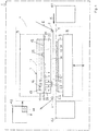
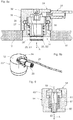
- the Figure 1 shows a schematic representation of a flat stamping printing machine 1.
- the machine 1 contains a flat bed press 4 with an embossing table 8 and a press head 7.
- the embossing table 8 comprises a counter pressure plate 9.
- a base plate 10 with an induction heating device 3 is arranged on the press head 7.
- the base plate 10 has a plate rear side 11 with a first support surface and a tool plate side 12 opposite the plate rear side 11 with a second support surface.
- the base plate 10 rests flat against a fastening component of the press head 7 with the support surface of the rear side 11 of the plate and is mechanically connected to it.
- the press head 7 further comprises a tool plate 20. This forms a plate rear side 35 with a first support surface and a tool side 36 opposite the plate rear side 35 with a tool receiving surface (see also FIG Figure 2 ).
- the tool plate 20 rests with the contact surface of the rear side 35 of the plate against the contact surface of the tool plate side 12 of the base plate 10.
- the tool plate 20 is releasably attached to the press head 7.
- Embossing tools 23 are detachably attached to the tool side 36 of the tool plate 20.
- the tool plate 20 is designed as a honeycomb foundation and contains a honeycomb region 22 for fastening the embossing tools, which forms a fastening zone with a plurality of blind holes 31 running transversely to the support surface.
- a feed device 41 for the flat material 5 and a removal device 42 for the flat material 5 are also shown schematically.
- the flat stamping printing machine 1 is designed as a sheet-fed machine
- the flat material 5 is present as a sheet 5.1.
- the feed device 41 comprises a feeder and the removal device 42 comprises a boom.
- the flat stamping printing machine 1 is designed as an endless web machine
- the flat material 5 is present as an endless web 5.2.
- the feed device 41 comprises an unwinding unit and the removal device 42 comprises a winding unit.
- the flat stamping printing machine 1 further comprises a film web guide 2 for guiding a stamping film web 6 through the stamping area between the tool plate 20 and the counter pressure plate 9.
- the flat stamping printing machine 1 further comprises a machine control 43 for controlling the flat bed press 4 as well as the film web guide 2 and the feed and removal device 41, 42.
- the heating device 3 further comprises a regulating device 44 for regulating the temperature of the tool plate 20.
- the regulating device 44 is integrated into the machine control 43 here.
- the embossing foil and flat material 5 are inserted and positioned between the tool plate 20 and the counter pressure plate 9. While the flat material 5 is being introduced in the process direction X, the embossing foil can also be introduced in the process direction X or against the process direction X.
- the flat material 5 rests on the counter-pressure plate 9.
- the stamping foil 6 is arranged between the flat material 5 and the tool plate 20.
- the embossing table 8 By moving up (see arrows) the embossing table 8, the counter-pressure plate 9 is pressed against the stationary tool plate 20 while applying an embossing pressure. After completion of the embossing process, the embossing table 8 with the counter-pressure plate 9 is moved downwards again. The embossing table 8 thus carries out an embossing stroke H. The embossed flat material 5 is then moved on in the process direction X.
- a compressed air device 40 for generating a blown air flow for the purpose of separating the embossed flat material 5 from the film web 6 is arranged on the exit side of the embossing area in the process direction X (see FIG Figure 3 , 6 and 7 ).
- the compressed air device 40 is z. B. a fan.
- the embossing tools 23 must first be heated to an embossing temperature.
- the base plate 10 is part of an induction heating device 3.
- An inductor 16 in the form of a flat coil (see also FIG Figure 4 ) is embedded in the base plate 10 and arranged between the tool plate side 12 and the rear side 11 of the plate.
- the inductor 16 is inserted from the plate rear 11 into slot openings 33 in the base plate 10 and in this z. B. glued with an adhesive or potted with a potting material.
- the slot openings 33 are correspondingly open towards the rear side 11 of the plate.
- the flat coil 16 is arranged plane-parallel to the support surface on the tool plate side 12.
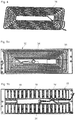
- the Figure 5a shows a plan view of the base plate 10 towards the rear side 11 of the plate.
- the back side of the plate 11 shows, among other things, the slot openings 33 for the flat coil 16 and a through opening 34 for the sensor unit 26, which will be described further below.
- the carrier material 13 of the base plate 10 is a glass fiber reinforced plastic and is accordingly not electrically conductive, but permeable to the generated alternating magnetic field 19.
- the inductor 16 is fed with an alternating current in order to put the induction heating device 3 into operation.
- the design and arrangement of the inductor 16 now generates an alternating magnetic field 19 which penetrates into the base area 21 of the tool plate 20 and heats it inductively.
- ferrimagnetic bodies 18 are arranged in the base plate 10 between the support surface of the rear side 11 of the plate and the inductor 16. The ferrimagnetic bodies 18 are let into recesses in the base plate 10 from the rear side 11 of the plate. The ferrimagnetic bodies 18 are used to deflect the alternating magnetic field towards the die plate 20 and thus also to shield the rest of the press head 7 on the plate rear 11.
- the Figure 5b shows the top view of a heating module looking towards the rear side 11 of the base plate 10.
- the heating module comprises the flat coil 16 inserted into the slot openings 33 of the base plate and the above-mentioned ferrimagnetic bodies 18, which are also located in depressions in the base plate 10 between the flat coil 16 and the Support surface of the plate back 11 are arranged.
- the rear side 11 of the base plate 10 is a shielding element 17 in the form of an aluminum sheet with a thickness of, for. B. 0.2 mm at ( Figure 2 ).
- the shielding element 17 serves to shield the rest of the press head 7 from the alternating magnetic field. This is intended to prevent inductive heating of the rest of the press head 7.
- the shielding element 17 can also be part of the heating module.
- the thermal energy inductively generated in the base area 21 of the tool plate 20 is now conducted by means of heat conduction to the tool side 36 and from there into the embossing tools 23.
- the heat conduction within the continuous base area 21, parallel to the support surface of the rear side of the plate ensures a homogeneous temperature over the entire extent of the tool plate 20.
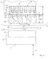
- the Figure 6 shows a particular embodiment of an induction heating device for a continuous web machine with four heating modules, each with a base plate 10.1 to 10.4 and an inductor.
- the four heating modules are arranged one behind the other on the rear side of the tool plate 20 in the process direction X.
- the tool plate 20 is in Figure 6 for the sake of completeness still drawn in dotted lines.
- the tool plate 20 has a length L in the process direction X and a width B transverse to the process direction X.
- a compressed air device 40 for generating a blown air flow, which is arranged on the inlet and outlet side, is also shown.
- the Figure 7 shows an embodiment for a sheet-fed machine with a total of six heating modules 10.1 to 10.6.
- heating modules 10.3 to 10.6 are arranged next to one another at right angles to the process direction X.
- two further heating modules 10.3 to 10.6 are arranged next to one another at right angles to the process direction X.
- blown air is blown in on the output side and optionally also on the input side of the embossing area by means of a compressed air device 40, the input-side or output-side subzone cools down faster than the central subzones of the heating zone.
- each heating module has a temperature sensor 25.1 to 25.4 ( Figure 6 ) or 25.1 to 25.6 ( Figure 7 ), with which the temperature in the corresponding sub-zone is measured.
- the Figure 3 shows a schematic cross-sectional view through the embossing area of an embossing printing machine with a tool plate 20 and two heating modules arranged next to one another on the back of the plate 35, each with a base plate 10.1, 10.2.
- the heating modules can be operated individually, so that, viewed in the process direction X, a front and a rear partial zone of the heating zone formed by the base area 21 can be heated independently of one another.
- the respective heating module contains a temperature measuring device with a temperature sensor 25.1, 25.2 (see also Figures 8a, 8b ).
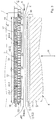
- the Figures 8a and 8b show a first embodiment of a temperature measuring device 24 with a sensor unit 26.
- the sensor unit 26 comprises a temperature sensor 25 which is attached to the end of a movable sensor carrier 30 and is directed towards the support surface of the base plate 10.
- the sensor carrier 30 is in the form of a sleeve and forms the movable part of the sensor unit 26.
- the sensor unit 26 further comprises a housing 32 in which the sensor carrier 30 together with the temperature sensor 25 is displaceably guided along a movement axis A between a measuring position S1 and a set-up position S2 via a sliding guide.
- a tension spring 27 acts as a restoring element, which returns the sensor carrier 30 together with the temperature sensor 25 to the set-up position S2 or holds it in it.
- the above-mentioned elements together form a movement mechanism for displacing the sensor carrier 30 with the temperature sensor 25.
- the sensor unit 26 is let into a through opening 34 in the base plate 10, the temperature sensor 25 being directed towards the tool plate side 12.
- the movement mechanism is driven by a pneumatic drive 28.
- a gas pressure is thus built up in the cavity of the sensor carrier 30 via a pneumatic line. If the compressive force exerted on the sleeve by the gas pressure exceeds the restoring force of the tension spring 27, the sensor carrier 30 is moved from the set-up position S2 into the measuring position S1.
- the control of the pneumatic drive 28 and thus the position of the temperature sensor takes place, for. B. via the machine control 43.
- a sensor line 59 is provided, which is led from the temperature sensor 25 through the cavity of the sensor carrier 30 to the outside.
- the temperature measuring device described above is particularly suitable for flat stamping printing machines in which the tool plate is brought up to the base plate with a lateral movement component during assembly after (re) setting up, so that the tool plate has a protruding temperature sensor during assembly, e.g. B. by shearing, could damage.
- the second embodiment shown of a temperature measuring device differs from the first embodiment according to FIGS Figures 8a and 8b in that it does not contain any pneumatic device for the controlled movement of the sensor carrier in the base plate.
- the temperature measuring device 54 contains a sensor unit 56.
- the sensor unit 56 comprises a temperature sensor 55 which is attached to the end of a movable sensor carrier 60 and is directed towards the support surface on the tool plate side of the base plate.
- the sensor carrier 60 is in the form of a sleeve and forms the movable part of the sensor unit 56.
- the sensor unit 56 further comprises a housing 62 in which the movable sensor carrier 60 with the temperature sensor 55 is movably guided along a movement axis A via a sliding guide.
- the sensor unit 56 is let into a through opening in the base plate, the temperature sensor 55 being directed towards the tool plate side.
- the sliding guide is formed by a guide sleeve 61 which is fixedly arranged in the housing 62.
- the movable sensor carrier 60 forms a particular one for this purpose cylindrical sliding section, over which the sensor carrier 60 is slidably guided along an in particular cylindrical sliding section of the sliding sleeve 61.
- the sliding sections are in particular circular cylindrical. The sliding section of the movable sensor carrier 60 engages over the sliding section of the sliding sleeve 61 or - as in FIG Figure 9 shown - intervenes in this.
- the sliding sections of the two sleeves 60, 61 are surrounded by a compression spring 57 in the form of a helical spring.
- a compression spring 57 in the form of a helical spring.
- One end of the compression spring 57 rests against a stop on the sensor carrier 60 and the other end rests against a stop on the guide sleeve 61.
- the compression spring 57 serves as a restoring element which moves the pressure-relieved sensor carrier 60 together with the temperature sensor 55 into the set-up position and holds it in this position.
- the end portion of the sensor sleeve 60 with the temperature sensor 55 protrudes in the set-up position, for. B. by around 0.5 mm, beyond the contact surface of the base plate (see Figure 9 ).
- the temperature measuring device described above is particularly suitable for flat stamping printing machines in which the tool plate is brought up to the base plate perpendicular to the support surface of the base plate during assembly after the (re) set-up, so that the tool plate cannot damage a protruding temperature sensor during assembly, but rather rather it pushes it back into the base plate. In this way, sufficient contact pressure of the temperature sensor on the tool plate in the operating position is guaranteed for the purpose of forming the measuring contact.
- a sensor line 59 is also provided, which is led from the temperature sensor 55 through the cavity of the sensor carrier 60 and the sliding guide 61 to the outside.
Description
Die Erfindung bezieht sich auf das Gebiet der Flachprägedruckmaschinen und betrifft eine Flachprägedruckmaschine sowie eine Werkzeugplatte für eine Flachprägedruckmaschine gemäss dem Oberbegriff der Ansprüche 1 und 15.The invention relates to the field of flat stamping printing machines and relates to a flat stamping printing machine and a tool plate for a flat stamping printing machine according to the preamble of
Prägedruckmaschinen werden unter anderem eingesetzt für Prägefoliendruck, Hologramm-Transfer, Blindprägen, Microembossing sowie Strukturprägen.Embossing printing machines are used, among other things, for embossing foil printing, hologram transfer, blind embossing, microembossing and structure embossing.
Beim Prägefoliendruck wird eine Prägefolie mit Hilfe eines Prägewerkzeuges und in der Regel unter Wärmeeinwirkung auf ein Flachmaterial "gepresst". Die übertragene Folie liegt dabei in einer Ebene mit dem Flachmaterial. Je nach Prägewerkzeug, Pressdruck und Flachmaterial entsteht eine kaum merkliche bis deutliche Einprägung des Flachmaterials. Das Flachmaterial ist dabei Träger der Prägung bzw. Druckprägung.In the case of foil stamping, a stamping foil is "pressed" onto a flat material with the aid of an embossing tool and, as a rule, under the action of heat. The transferred film lies in one plane with the flat material. Depending on the embossing tool, pressure and flat material, there is a barely noticeable to clear impression of the flat material. The flat material is the carrier of the embossing or printing embossing.
Flachprägedruckmaschinen stellen eine besondere Konstruktionsart von Prägedruckmaschinen dar und unterscheiden sich von anderen Prägedruckmaschinen unter anderem durch eine Flachbettpresse mit Pressenkopf und Pressentisch.Flat embossing printing machines represent a special type of construction of embossing printing machines and differ from other embossing printing machines, among other things, by a flat bed press with press head and press table.
Der Pressenkopf, welcher die Werkzeugplatte aufnimmt, entspricht dabei dem Pressenoberteil. Er stellt das Gegenstück zum Pressentisch, dem Pressenunterteil, dar, welcher die Gegendruckplatte aufnimmt.The press head, which receives the tool plate, corresponds to the upper part of the press. It represents the counterpart to the press table, the lower part of the press, which holds the counter pressure plate.
Flachprägedruckmaschinen zeichnen sich durch eine hohe Prägeleistung und Prägequalität aus. Deshalb eignen sich Flachprägedruckmaschinen auch für besonders anspruchsvolle Prägeaufgaben, wie die Herstellung von Banknoten.Flat stamping printing machines are characterized by a high stamping performance and stamping quality. This is why flat stamping printing machines are also suitable for particularly demanding stamping tasks, such as the production of banknotes.
Flachprägedruckmaschinen erlauben insbesondere eine registergenau Positionierung des Flachmaterials in der Prägezone sowie den Einsatz von hochempfindlichen Prägefolien.Flat embossing printing machines allow, in particular, precise positioning of the flat material in the embossing zone and the use of highly sensitive embossing foils.
Ferner zeichnen sich Flachprägedruckmaschinen auch durch optimale Betriebsbedingungen, wie gleichmässige Temperatur- und Druckverhältnisse im Bereich der Prägezone, aus.Flat embossing printing machines are also characterized by optimal operating conditions, such as uniform temperature and pressure conditions in the area of the embossing zone.
Typische Flachprägedruckmaschinen sind z.B. aus der
Die Veröffentlichungsschrift
Die Veröffentlichungsschrift
Die Veröffentlichungsschrift
Bei Prägedruckverfahren, wie Prägefoliendruck, werden die Prägewerkzeuge vor Beginn des Prägeprozesses mittels einer Heizvorrichtung auf eine Betriebstemperatur, z. B. auf 150 bis 200 °C, aufgeheizt. Die Betriebstemperatur ist beispielsweise so ausgelegt, dass eine Prägefolie mit einer Transferschicht aus Kunststoff während des Prägevorganges zwecks Erstellung einer Stoffschlussverbindung mit dem Flachmaterial durch die Wärme des Prägewerkzeuges aktiviert, insbesondere angeschmolzen, wird.In the case of embossing printing processes, such as embossing foil printing, the embossing tools are brought to an operating temperature, e.g. B. to 150 to 200 ° C, heated. The operating temperature is designed, for example, so that an embossing foil with a plastic transfer layer is activated, in particular melted, by the heat of the embossing tool during the embossing process in order to create a material connection with the flat material.
Für ein fehlerfreies Prägen und zwecks Erreichen höchster Prägequalität, ist es einerseits wichtig, die Prägewerkzeuge auf die optimale Betriebstemperatur zu erwärmen und während des Betriebes der Maschine auf dieser Temperatur zu halten. Andererseits ist es auch wichtig, dass die Betriebstemperatur über sämtliche Prägewerkzeuge gleich ist, und während des Betriebes der Maschine auch gleich gehalten werden kann. Nur auf diese Weise sind gleiche Prägebedingungen über die gesamte Werkzeugplatte garantiert, so dass keine Qualitätsunterschiede im geprägten Flachmaterial auftreten.For error-free embossing and in order to achieve the highest embossing quality, it is important, on the one hand, to heat the embossing tools to the optimum operating temperature and to keep them at this temperature while the machine is in operation. On the other hand, it is also important that the operating temperature is the same across all embossing tools and that it can be kept the same during operation of the machine. This is the only way to guarantee the same embossing conditions over the entire tool plate, so that there are no quality differences in the embossed flat material.
Der Heizvorgang ist jedoch beim Thema Prägequalität nicht nur bezüglich der Einstellung der optimalen Betriebstemperatur der Prägewerkzeuge von grosser Bedeutung. Mit dem Aufheizen der Maschine findet auch eine Wärmeausdehnung von erwärmten Maschinenteilen statt. Diese Wärmeausdehnung muss beim Einstellen der Prägegeometrien bereits im Vorfeld berücksichtigt werden. Nur so wird eine präzise Prägung erreicht. Folglich ist es äusserst wichtig, dass die Maschine auf jener optimalen Betriebstemperatur betrieben wird, auf welche die Prägegeometrie vorab eingestellt worden ist.When it comes to stamping quality, however, the heating process is not only of great importance in terms of setting the optimum operating temperature of the stamping tools. As the machine heats up, the heated machine parts also expand. This thermal expansion must be taken into account in advance when setting the embossing geometries. This is the only way to achieve precise embossing. Consequently, it is extremely important that the machine is operated at the optimum operating temperature to which the embossing geometry has been set in advance.
Aus dem Stand der Technik sind nun Flachprägedruckmaschinen mit Heizvorrichtungen zum Aufheizen der Prägewerkzeuge bekannt, welche als elektrische Widerstandsheizungen ausgelegt sind. Das Aufheizen der Prägewerkzeuge auf die Betriebstemperatur mittels solcher Widerstandsheizungen nimmt jedoch sehr viel Zeit in Anspruch. So ist es nicht unüblich, dass vom Zeitpunkt der Zuschaltung der Heizvorrichtung bis Erreichen der optimalen Betriebstemperatur mehrere Stunden, z. B. 5 bis 6 Stunden, vergehen.Flat embossing printing machines with heating devices for heating the embossing tools, which are designed as electrical resistance heaters, are now known from the prior art. The heating of the embossing tools to the operating temperature by means of such resistance heaters, however, takes a lot of time. It is not uncommon for several hours, e.g. B. 5 to 6 hours pass.
Dies liegt insbesondere daran, weil die thermische Energie vom Heizwiderstand der Widerstandsheizung mittels Wärmeleitung zuerst in die Werkzeugplatte und über diese in die auf der Werkzeugplatte montierten Prägewerkzeuge eingeleitet werden muss.This is due in particular to the fact that the thermal energy from the heating resistor of the resistance heater must first be introduced into the tool plate by means of heat conduction and via this into the stamping tools mounted on the tool plate.
Ferner wird bei herkömmlichen elektrischen Widerstandsheizungen insbesondere auch der übrige Pressenkopf oder Teile davon aufgeheizt, da die Wärmeleitung in alle Richtungen erfolgt.Furthermore, with conventional electrical resistance heaters, the rest of the press head or parts thereof are also heated in particular, since the heat is conducted in all directions.
Die nun ebenfalls, allerdings ungewollt aufgeheizten Bauteile des Pressenkopfs unterliegen jedoch auch der Wärmeausdehnung, welche wiederum die Prägegenauigkeit beeinflusst. Daher kann der Prägeprozess erst aufgenommen werden, wenn auch der Pressenkopf auf eine stabile Betriebstemperatur aufgeheizt ist. Dies wird vorgängig bei den Prägeeinstellungen entsprechend berücksichtigt.The components of the press head, which are also heated up unintentionally, are, however, also subject to thermal expansion, which in turn influences the stamping accuracy. Therefore, the embossing process can only be started, albeit the press head is heated to a stable operating temperature. This is taken into account in advance in the embossing settings.
Die stabile Betriebstemperatur der gesamten Maschine, bei welcher keine weitere thermische Expansion einzelner Maschinenteile mehr auftritt, wird daher nur sehr langsam erreicht. Daraus resultiert die oben genannte, lange Aufheizzeit.The stable operating temperature of the entire machine, at which no further thermal expansion of individual machine parts occurs, is therefore only reached very slowly. This results in the long heating time mentioned above.
Im Rahmen des Bestrebens, einerseits die Produktivität zu steigern und andererseits die Betriebskosten zu senken, ist es eine Aufgabe vorliegender Erfindung, eine Flachprägedruckmaschine mit Heizvorrichtung vorzuschlagen, welche sich durch eine erheblich verkürzte Aufheizzeit auszeichnet.As part of the endeavor to increase productivity on the one hand and to reduce operating costs on the other, it is an object of the present invention to propose a flat stamping printing machine with a heating device, which is characterized by a considerably reduced heating time.
Die Flachprägedruckmaschine soll sich zudem für anspruchsvolle Prägeaufgaben eignen und gegenüber herkömmlichen Flachprägedruckmaschine keine Einbusse in der Qualität der Prägeerzeugnisse aufweisen.The flat stamping printing machine should also be suitable for demanding stamping tasks and should not show any loss in the quality of the stamped products compared to conventional flat stamping printing machines.
Eine verkürzte Aufheizzeit führt nämlich ganz allgemein zu kürzeren Einstellungsund Umrüstzeiten und somit zu kürzeren Stillstandzeiten der Flachprägedruckmaschine.This is because a shortened heating-up time generally leads to shorter setting and retooling times and thus to shorter downtimes for the flat stamping printing machine.
Eine weitere Aufgabe vorliegender Erfindung ist es, eine Flachprägedruckmaschine mit Heizvorrichtung vorzuschlagen, welche sich durch tiefere Energiekosten auszeichnet.Another object of the present invention is to propose a flat stamping printing machine with a heating device, which is characterized by lower energy costs.
Eine weitere Aufgabe vorliegender Erfindung ist es, eine Flachprägedruckmaschine mit Heizvorrichtung vorzuschlagen, welche sich durch eine präzise, verzögerungsfreie Regelung der Werkzeugtemperatur auszeichnet. Die Heizvorrichtung bzw. die Temperaturregelung soll insbesondere das Aufheizen der Prägewerkzeuge auf eine bei sämtlichen Prägewerkzeugen gleiche Betriebstemperatur sowie das Halten dieser Betriebstemperatur erleichtern.Another object of the present invention is to propose a flat stamping printing machine with a heating device, which is characterized by precise, instantaneous regulation of the tool temperature. The heating device or the temperature control is intended, in particular, to make it easier to heat the stamping tools to an operating temperature that is the same for all of the stamping tools and to maintain this operating temperature.
Eine weitere Aufgabe vorliegender Erfindung ist es, eine Flachprägedruckmaschine mit Heizvorrichtung vorzuschlagen, mittels welcher sich möglichst zielgerichtet die Prägewerkzeuge aufheizen lassen, ohne dass weitere Maschinenteile unnötig aufgeheizt werden.A further object of the present invention is to propose a flat embossing printing machine with a heating device, by means of which the embossing tools can be heated as precisely as possible without further machine parts being unnecessarily heated.
Die oben genannten Aufgaben werden durch die Merkmale der unabhängigen Ansprüche 1 und 15 gelöst. Besondere Weiterbildungen und Ausführungsformen der Erfindung ergeben sich aus den abhängigen Ansprüchen, der Beschreibung und den Zeichnungen.The above-mentioned objects are achieved by the features of
Die Flachprägedruckmaschine enthält also:
- eine Werkzeugplatte, auch Klischeeplatte genannt, mit einer Werkzeugseite, auch Klischeeseite genannt, zur Aufnahme mindestens eines Prägewerkzeuges, auch Klischee genannt, und mit einer der Werkzeugseite gegenüber liegenden Werkzeugplattenrückseite;
- eine Grundplatte mit einer der Rückseite der Werkzeugplatte zugewandten Werkzeugplattenseite und einer der Werkzeugplattenseite gegenüber liegenden Grundplattenrückseite zur Übertragung einer auf die Werkzeugplatte ausgeübten Prägekraft zwischen der Werkzeugplattenseite und der Grundplattenrückseite; und
- eine Heizvorrichtung zum Beheizen des mindestens einen Prägewerkzeugs.
- a tool plate, also called cliché plate, with a tool side, also called cliché side, for receiving at least one embossing tool, also called cliché, and with a back side of the tool plate opposite the tool side;
- a base plate with a tool plate side facing the rear side of the tool plate and a base plate rear side opposite the tool plate side for transmitting an embossing force exerted on the tool plate between the tool plate side and the base plate rear side; and
- a heating device for heating the at least one embossing tool.
Werkzeugplatte mit Prägewerkzeug und die Grundplatte sind insbesondere Teil eines Pressenkopfes. Die Grundplatte ist dabei mit ihrer Plattenrückseite dem Pressenkopf zugewandt. Die Grundplatte ist insbesondere über die Plattenrückseite am Pressenkopf befestigt.Tool plate with stamping tool and the base plate are in particular part of a press head. The back of the base plate faces the press head. The base plate is attached to the press head in particular via the back of the plate.
Der Pressenkopf ist insbesondere oberhalb eines Pressentisches, auch Prägetisch, genannt, angeordnet, welcher eine Gegendruckplatte umfasst.The press head is in particular arranged above a press table, also called an embossing table, which comprises a counter-pressure plate.
Zur Ausführung eines Prägevorganges wird ein Flachmaterial und eine Prägefolienbahn zwischen Werkzeugplatte und Gegendruckplatte, welche voneinander beabstandet sind, eingeführt. Der Prägedruck erfolgt durch das Zusammenführen von Werkzeugplatte mit Prägewerkzeug und Gegendruckplatte unter Ausübung eines Pressdruckes.To carry out an embossing process, a flat material and an embossing film web are introduced between the tool plate and the counter pressure plate, which are spaced apart from one another. The embossing pressure is carried out by bringing together the tool plate with the embossing tool and the counter pressure plate while applying pressure.
Gemäss einer gängigen Ausführung einer Flachprägedruckmaschine wird beim Prägevorgang die Gegendruckplatte zur stationären Werkzeugplatte hin bewegt. Der Pressendruck wird folglich von der Gegendruckplatte bzw. Pressentisch auf die Werkzeugplatte bzw. den Pressenkopf ausgeübt. Bei diesem Vorgang wird der Pressendruck von der Werkzeugplatte über die Grundplatte in den übrigen Pressenkopf eingeleitet.According to a common design of a flat stamping printing machine, the counter-pressure plate is moved towards the stationary tool plate during the stamping process. The press pressure is consequently exerted by the counter pressure plate or press table on the tool plate or the press head. During this process, the press pressure is transferred from the die plate to the rest of the press head via the base plate.
Da die Flachprägedruckmaschine bezüglich der Prägewerkzeuge umrüstbar sein muss, ist die Werkzeugplatte insbesondere über eine Halterung lösbar am Pressenkopf befestigt. Zum Auswechseln der Prägewerkzeuge wird die Werkzeugplatte vom Pressenkopf gelöst und z. B. über eine Führungseinrichtung in eine Rüstposition bewegt, in welcher die Werkzeugplatte mit Prägewerkzeugen bestückt werden kann.Since the flat stamping printing machine must be convertible with respect to the stamping tools, the tool plate is fastened to the press head in a detachable manner, in particular via a holder. To change the embossing tools, the tool plate is released from the press head and z. B. moved via a guide device into a set-up position in which the tool plate can be equipped with embossing tools.
Nach erfolgter Umrüstung wird die Werkzeugplatte über die Führungseinrichtung wieder in ihre Betriebsposition zurück bewegt und mittels Halterung am Pressenkopf befestigt.After the conversion, the tool plate is moved back into its operating position via the guide device and fastened to the press head by means of a bracket.
Die Grundplatte verbleibt bei diesem Vorgang insbesondere stationär am Pressenkopf. Die Grundplatte kann allerdings ebenfalls lösbar am Pressenkopf befestigt sein.During this process, the base plate remains, in particular, stationary on the press head. The base plate can, however, also be releasably attached to the press head.
Die Heizvorrichtung ist nun eine Induktionsheizvorrichtung mit einem Induktor. In einer Induktionsheizvorrichtung wird mittels eines von Wechselstrom durchflossenen Induktors ein magnetisches Wechselfeld erzeugt, welches in einem zu erwärmenden, elektrisch leitfähigen Körper Wirbelströme und gegebenenfalls auch Ummagnctisierungsverluste induziert, welche eine Erwärmung des Körpers bewirken. Der Induktor ist also ein induktives Heizmittel.The heater is now an induction heater with an inductor. In an induction heating device, an alternating magnetic field is generated by means of an inductor through which alternating current flows, which produces eddy currents and possibly also magnetic reversal losses in an electrically conductive body to be heated induced, which cause the body to warm up. The inductor is therefore an inductive heating means.
Der Induktor ist derart ausgebildet und zwischen der Werkzeugplattenseite und Grundplattenrückseite angeordnet, dass ein auf der Werkzeugplattenseite über die Grundplatte hinausreichendes magnetisches Wechselfeld zum induktiven Heizen einer induktiv heizbaren Werkzeugplatte jenseits der Werkzeugplattenseite und ausserhalb der Grundplatte erzeugt werden kann.The inductor is designed and arranged between the tool plate side and the base plate rear side that an alternating magnetic field extending beyond the base plate on the tool plate side can be generated for inductive heating of an inductively heatable tool plate on the other side of the tool plate side and outside the base plate.
Das magnetische Wechselfeld reicht insbesondere in die Werkzeugplatte hinein.The alternating magnetic field extends into the tool plate in particular.
Die Induktionsheizvorrichtung enthält insbesondere eine Einrichtung zur Bereitstellung von Wechselstrom mit der benötigen Frequenz. Die Einrichtung kann insbesondere eine Leistungseinheit, z.B. mit einem Frequenzumrichter, umfassen, welche die elektrische Leistung in der benötigten Frequenz zur Verfügung stellt.The induction heating device contains, in particular, a device for providing alternating current at the required frequency. The device can in particular comprise a power unit, e.g. with a frequency converter, which provides the electrical power at the required frequency.
Die Wärme entsteht also unmittelbar im zu erwärmenden Körper selbst und muss folglich nicht durch Wärmeleitung auf diesen übertragen werden. Entsprechend ist die Wärmeleistung gut steuerbar und der Wirkungsgrad insbesondere bei ferromagnetischen Materialien sehr hoch.The heat is generated directly in the body to be heated and consequently does not have to be transferred to it by conduction. Accordingly, the heat output can be easily controlled and the efficiency is very high, especially with ferromagnetic materials.
Die Induktionsheizvorrichtung ist nun dazu ausgelegt, die Werkzeugplatte induktiv aufzuheizen, wobei ein magnetisches Wechselfeld mittels Induktor gezielt in der Werkzeugplatte angelegt wird.The induction heating device is now designed to inductively heat the tool plate, with an alternating magnetic field being applied in a targeted manner in the tool plate by means of an inductor.
Die Prägewerkzeuge werden durch Wärmeleitung indirekt über die Werkzeugplatte aufgeheizt.The embossing tools are heated up indirectly via the tool plate through thermal conduction.
Die Induktionsheizvorrichtung kann auch dazu ausgelegt sein, zusätzlich die auf der Werkzeugplatte montierten Prägewerkzeuge induktiv aufzuheizen. In diesem Fall wird das magnetische Wechselfeld mittels Induktor auch in den Prägewerkzeugen angelegt.The induction heating device can also be designed to additionally inductively heat the stamping tools mounted on the tool plate. In this case the alternating magnetic field is also applied to the embossing tools by means of an inductor.
So kann die Induktionsheizvorrichtung sowohl die Prägewerkzeuge als auch die Werkzeugplatte induktiv aufheizen, gegebenenfalls mit unterschiedlichen Wirkungsgraden.Thus, the induction heating device can inductively heat both the stamping tools and the tool plate, possibly with different degrees of efficiency.
Allerdings können die Prägewerkzeuge je nach Anwendungsbereich, d.h. je nach den zu prägenden Materialien sowie in Abhängigkeit von den herrschenden Prägedrücken und Prägetemperaturen aus unterschiedlichen Werkstoffen wie Messing, Stahl, Magnesium oder Aluminium gefertigt sein. Einige dieser Metalle weisen keine besonders guten induktiven Eigenschaften auf, so dass sich die Prägewerkzeuge vergleichsweise schlecht, d.h. insbesondere mit schlechtem Wirkungsgrad, oder gar nicht induktiv aufheizen lassen.However, the stamping tools can be made of different materials such as brass, steel, magnesium or aluminum, depending on the area of application, i.e. depending on the materials to be stamped and depending on the prevailing stamping pressures and stamping temperatures. Some of these metals do not have particularly good inductive properties, so that the embossing tools are comparatively poor, i.e. particularly with poor efficiency, or cannot be heated inductively at all.
Ein direktes, induktives Aufheizen der Prägewerkzeuge ohne die Werkzeugplatte ebenfalls induktiv aufzuheizen, steht deshalb nicht im Vordergrund. Dies auch deshalb, weil die Masse der Werkzeugplatte für eine stabile Betriebstemperatur ebenfalls aufgeheizt werden muss. Dies geschieht schneller und effizienter, wenn die Werkzeugplatte direkt induktiv aufgeheizt wird und nicht indirekt durch Wärmeleitung über die Prägewerkzeuge.Direct, inductive heating of the embossing tools without inductively heating the tool plate is therefore not in the foreground. This is also because the mass of the mold plate must also be heated for a stable operating temperature. This happens faster and more efficiently if the tool plate is heated inductively directly and not indirectly through heat conduction via the embossing tools.
Da die Wärme in der Werkzeugplatte erst durch die Wechselwirkung zwischen der Werkzeugplatte und dem magnetischen Wechselfeld erzeugt wird, kann die Werkzeugplatte auch als Teil der Induktionsheizvorrichtung betrachtet werden.Since the heat in the tool plate is only generated by the interaction between the tool plate and the alternating magnetic field, the tool plate can also be viewed as part of the induction heating device.
Induktives Heizen weist neben dem höheren Wirkungsgrad auch den Vorteil auf, dass die induktive Wirkung durch nichtleitende Materialien, wie Kunststoff, hindurch erfolgen kann, ohne dass die nichtleitenden Materialien induktiv erwärmt werden. So können zwischen Induktor und der Heizzone, in welcher induktiv geheizt wird, nicht leitende Körper angeordnet sein, welche den Heizvorgang nicht beeinträchtigen.In addition to the higher degree of efficiency, inductive heating also has the advantage that the inductive effect can take place through non-conductive materials, such as plastic, without the non-conductive materials being inductively heated. So between the inductor and the heating zone, in which inductive heating will be arranged, non-conductive body, which does not affect the heating process.
Gemäss Erfindung bildet die Werkzeugplatte im Zusammenwirken mit einem magnetischen Wechselfeld eine Heizzone aus einem induktiv erwärmbaren Werkstoff aus.According to the invention, the tool plate, in cooperation with an alternating magnetic field, forms a heating zone made of an inductively heatable material.
Die Heizzone in der Werkzeugplatte besteht insbesondere aus einem ferromagnetischen Material oder enthält ein solches. Es kann auch die gesamte Werkzeugplatte aus einem ferromagnetischen Material bestehen oder dieses enthalten. Die Werkzeugplatte kann insbesondere aus Sphäroguss, insbesondere GGG40, bestehen.The heating zone in the tool plate consists in particular of or contains a ferromagnetic material. The entire tool plate can also consist of or contain a ferromagnetic material. The tool plate can in particular consist of nodular cast iron, in particular GGG40.
Die Werkzeugplatte weist typischerweise eine Breite quer zur Prozessrichtung von 70 bis 110 cm und eine Länge in Prozessrichtung von 50 bis 80 cm auf. Die Höhe bzw. Dicke der Werkzeugplatte beträgt typischerweise 15 bis 20 mm.The tool plate typically has a width transverse to the process direction of 70 to 110 cm and a length in the process direction of 50 to 80 cm. The height or thickness of the tool plate is typically 15 to 20 mm.
Die Werkzeugplatte ist insbesondere einstückig ausgebildet.The tool plate is in particular formed in one piece.
Gemäss einer Weiterbildung der Erfindung bildet die Werkzeugplatte im Bereich der Werkzeugplattenrückseite einen durchgehenden, d.h. durchgängigen Bodenbereich aus. Die Höhe des Bodenbereichs kann z. B. von 1 bis 5 mm, insbesondere von 1 bis 3 mm, betragen. Durchgehend bzw. durchgängig bedeutet, dass der Bodenbereich unterbruchlos über die gesamte Fläche der Werkzeugplatte verläuft, d.h. keine Durchbrüche aufweist.According to a further development of the invention, the tool plate forms a continuous, i.e. continuous base area in the area of the rear side of the tool plate. The height of the floor area can e.g. B. from 1 to 5 mm, in particular from 1 to 3 mm. Continuous or continuous means that the floor area runs uninterrupted over the entire surface of the tool plate, i.e. has no openings.
Die in der Werkzeugplatte ausgebildete Heizzone umfasst dabei insbesondere den durchgängigen Bodenbereich. Dank des durchgängigen Bodenbereichs findet eine gleichmässige und schnelle Querverteilung der im Bodenbereich induktiv erzeugten thermischen Energie statt.The heating zone formed in the tool plate includes in particular the continuous floor area. Thanks to the continuous floor area, the thermal energy generated inductively in the floor area is distributed quickly and evenly across the floor.
Die Induktionsheizvorrichtung ist entsprechend so ausgelegt, dass das magnetische Wechselfeld in die Werkzeugplatte und insbesondere in dessen Bodenbereich gerichtet ist. Die in der Werkzeugplatte erzeugten Wirbelströme sorgen für eine rasche und gleichmässige Erwärmung derselbigen.The induction heating device is designed accordingly in such a way that the alternating magnetic field is directed into the tool plate and, in particular, into its base area. The eddy currents generated in the mold plate ensure that it is heated quickly and evenly.
Gemäss einer Weiterbildung der Werkzeugplatte enthält diese eine Mehrzahl von Vertiefungen, welche zur Werkzeugseite hin offen sind und zur Plattenrückseite hin vom durchgängigen Bodenbereich abgelöst werden. D. h. die Vertiefungen sind zwischen der Werkzeugseite und Plattenrückseite nicht durchgängig ausgebildet sondern werden vom Bodenbereich begrenzt. Die Vertiefungen verlaufen quer zu den durch die Werkzeugseite und Plattenrückseite ausgebildeten Auflageflächen.According to a further development of the tool plate, it contains a plurality of depressions which are open towards the tool side and are detached from the continuous bottom area towards the rear side of the plate. I. E. the recesses are not continuously formed between the tool side and the back of the plate but are delimited by the bottom area. The depressions run transversely to the support surfaces formed by the tool side and the back of the plate.
Die Vertiefungen dienen als Befestigungshilfe für die an der Werkzeugseite lösbar befestigten Prägewerkzeuge. Sie bilden in der Werkzeugplatte folglich eine Befestigungszone aus.The depressions serve as a fastening aid for the embossing tools which are detachably fastened on the tool side. They consequently form a fastening zone in the tool plate.
Die Vertiefungen können mittels Bohren oder Fräsen in die Werkzeugplatte eingebracht sein. Die Vertiefungen sind insbesondere als Bohrungen in der Werkzeugplatte ausgeführt. Die Vertiefungen sind insbesondere Sacklöcher.The depressions can be made in the tool plate by means of drilling or milling. The depressions are designed in particular as bores in the tool plate. The depressions are in particular blind holes.
Es ist jedoch auch denkbar, dass die Werkzeugplatte mehrteilig ausgebildet ist und z. B. eine Trägerplatte mit durchgängigen Löchern sowie eine auf ihrer Rückseite anliegende Bodenplatte umfasst. Die Bodenplatte bildet den durchgängigen Bodenbereich aus. Die Bodenplatte ist aus einem ferromagnetischen Werkstoff oder enthält diesen. Die Bodenplatte kann über eine Stoffschlussverbindung wie Löten oder Schweissen mit der Trägerplatte verbunden sein. Eine mechanische Verbindung ist auch denkbar.However, it is also conceivable that the tool plate is constructed in several parts and z. B. comprises a carrier plate with continuous holes and a base plate resting on its rear side. The floor slab forms the continuous floor area. The base plate is made of or contains a ferromagnetic material. The base plate can be connected to the carrier plate via a material connection such as soldering or welding. A mechanical connection is also conceivable.
Eine besondere Ausführung einer solchen Werkzeugplatte ist das im Stand der Technik bekannte Wabenfundament. Allerdings unterscheidet sich die vorliegende Werkzeugplatte vom bekannten Wabenfundament dadurch, dass die Vertiefungen in der Werkzeugplatte nicht als von der Werkzeugseite zur Plattenrückseite durchgängige Löcher ausgebildet sind, sondern zur Plattenrückseite hin vielmehr abgeschlossen sind und im Übergang zum durchgängigen Bodenbereich enden.A special embodiment of such a tool plate is the honeycomb foundation known in the prior art. However, the present one differs Tool plate from the known honeycomb foundation in that the depressions in the tool plate are not designed as continuous holes from the tool side to the rear of the plate, but rather are closed off towards the rear of the plate and end in the transition to the continuous floor area.
Der Induktor ist insbesondere als gewundener elektrischer Leiter ausgebildet. Seine Krümmungen sind insbesondere in einer Ebene parallel zur Auflagefläche, welche an der Werkzeugplattenseite ausgebildet wird, angeordnet. Der Induktor kann insbesondere eine Flachspule, wie Spiral-Flachspule, sein.The inductor is designed in particular as a coiled electrical conductor. Its curvatures are in particular arranged in a plane parallel to the support surface which is formed on the tool plate side. The inductor can in particular be a flat coil, such as a spiral flat coil.
Die Grundplatte bildet auf der Werkzeugplattenseite eine ebene Auflagefläche aus. Die Auflagefläche ist, allenfalls mit Ausnahme eines Durchbruchs für einen Temperatursensor, insbesondere durchgängig.The base plate forms a flat support surface on the tool plate side. With the exception of an opening for a temperature sensor, the support surface is in particular continuous.
Die Grundplatte bildet auf ihrer Rückseite eine ebene Auflagefläche aus. Die Auflagefläche ist insbesondere nicht durchgängig ausgebildet. Die Auflagefläche kann insbesondere von Vertiefungen bzw. Ausnehmungen zur Aufnahme des Induktors bzw. von Feldleitelementen unterbrochen sein.The base plate forms a flat support surface on its back. In particular, the support surface is not designed to be continuous. The support surface can in particular be interrupted by depressions or recesses for receiving the inductor or field guide elements.
Über die genannten Auflageflächen werden insbesondere die eingangs genannten Prägedrücke zwischen der Werkzeugplatte und dem übrigen Pressenkopf übertragen.In particular, the aforementioned embossing pressures are transmitted between the tool plate and the rest of the press head via the aforementioned contact surfaces.
Gemäss einer Weiterbildung der Erfindung nimmt die Grundplatte den Induktor auf. Das heisst, der Induktor ist in die Grundplatte eingelassen. Eingelassen bedeutet insbesondere dass der Induktor sich nicht über die Auflagefläche der Rückseite hinaus erstreckt.According to a further development of the invention, the base plate accommodates the inductor. This means that the inductor is embedded in the base plate. Recessed means in particular that the inductor does not extend beyond the support surface on the rear side.
Grundplatte und Induktor sind so gemeinsam Teil eines Heizmoduls.The base plate and inductor are thus part of a heating module.
Der Induktor kann zum Beispiel in Vertiefungen bzw. Ausnehmungen der Grundplatte eingelassen sein. Die Vertiefungen bzw. Ausnehmungen können z. B. schlitzförmig sein.The inductor can, for example, be embedded in depressions or recesses in the base plate. The depressions or recesses can, for. B. be slot-shaped.
Die Vertiefungen bzw. Ausnehmungen sind zur Grundplattenrückseite hin offen.The depressions or recesses are open towards the rear of the base plate.
Die Grundplatte weist zur Werkzeugplattenseite hin insbesondere einen Bodenbereich auf. Die Vertiefungen bzw. Ausnehmungen für den Induktor sind zur Werkzeugplattenseite hin insbesondere durch den Bodenbereich begrenzt.The base plate has, in particular, a floor area towards the tool plate side. The depressions or recesses for the inductor are delimited towards the tool plate side, in particular by the base area.
Der Bodenbereich ist, allenfalls mit Ausnahme eines Durchbruchs für einen Temperatursensor, insbesondere durchgängig.With the exception of an opening for a temperature sensor, the floor area is in particular continuous.
Der Induktor kann zum Beispiel in den Vertiefungen bzw. Ausnehmungen der Grundplatte eingegossen oder verklebt sein.The inductor can, for example, be cast or glued into the depressions or recesses of the base plate.
Es ist allerdings auch möglich, dass der Induktor bereits bei der Herstellung der Grundplatte in die Grundplatte integriert wird. In diesem Fall ist der Induktor allseitig von Trägermaterial der Grundplatte umschlossen. Die Werkzeugseite und die Rückseite weisen beide, allenfalls mit Ausnahme eines Durchbruchs für einen Temperatursensor, eine durchgängige Auflagefläche auf.However, it is also possible for the inductor to be integrated into the base plate during the manufacture of the base plate. In this case, the inductor is enclosed on all sides by the carrier material of the base plate. The tool side and the rear side both have a continuous support surface, possibly with the exception of an opening for a temperature sensor.
Gemäss einer Weiterbildung der Erfindung sind zwischen dem Induktor und der Grundplattenrückseite Feldleitelemente mit ferrimagnetischen Eigenschaften angeordnet. Die Feldleitelemente dienen der Umlenkung und gegebenenfalls auch der Modulierung des magnetischen Wechselfeldes. Damit soll erreicht werden, dass das magnetische Wechselfeld einerseits optimal in die Werkzeugplatte geleitet wird und andererseits möglichst nicht in den übrigen Pressenkopf eindringt. Mit dieser Massnahme kann eine unerwünschte Erwärmung des übrigen Pressenkopfes verhindert oder zumindest reduziert werden.According to a further development of the invention, field guide elements with ferrimagnetic properties are arranged between the inductor and the rear side of the base plate. The field guide elements serve to deflect and, if necessary, also to modulate the magnetic alternating field. This is to ensure that the alternating magnetic field on the one hand is optimally directed into the die plate and on the other hand, if possible, does not penetrate the rest of the press head. With this measure, undesired heating of the rest of the press head can be prevented or at least reduced.
Die Feldleitelemente können z. B. Ferritkörper sein.The field guide elements can, for. B. be ferrite body.
Gemäss einer Weiterbildung der Erfindung nimmt die Grundplatte die Feldleitelemente auf. Das heisst, die Feldleitelemente sind in die Grundplatte eingelassen. Eingelassen bedeutet insbesondere dass die Feldleitelemente sich nicht über die Auflagefläche der Plattenrückseite hinaus erstrecken.According to a further development of the invention, the base plate accommodates the field guiding elements. This means that the field guiding elements are embedded in the base plate. Recessed means in particular that the field guide elements do not extend beyond the support surface of the back of the plate.
Die Feldleitelemente können Teil des oben erwähnten Heizmoduls sein.The field guiding elements can be part of the heating module mentioned above.
Die Feldleitelemente können zum Beispiel in Vertiefungen bzw. Ausnehmungen der Grundplatte eingelassen sein. Die Feldleitelemente können auch, wie oben als alternative Variante erörtert, zusammen mit dem Induktor ebenfalls bei der Herstellung der Grundplatte in diese integriert werden.The field guide elements can, for example, be embedded in depressions or recesses in the base plate. As discussed above as an alternative variant, the field guide elements can also be integrated into the base plate together with the inductor during the manufacture of the base plate.
Gemäss einer Weiterbildung der Erfindung ist auf der Grundplattenrückseite ein flächiges Abschirmelement mit wenigstens einer Schicht aus einem elektrisch leitenden Material angeordnet. Das Abschirmelement deckt die Auflagefläche der Grundplattenrückseite flächig ab, insbesondere vollflächig. Das Abschirmelement liegt der Auflagefläche insbesondere an.According to a further development of the invention, a flat shielding element with at least one layer made of an electrically conductive material is arranged on the back of the base plate. The shielding element covers the contact surface of the back of the base plate over an area, in particular over the entire area. In particular, the shielding element rests against the support surface.
Das Abschirmelement ist nicht oder nur wenig induktiv erwärmbar. Das Abschirmelement schirmt auf diese Weise den übrigen Pressenkopf im rückseitigen Bereich der Grundplatte wenigstens teilweise vom magnetischen Wechselfeld ab, ohne dass das Abschirmelement selbst ebenfalls nennenswert erwärmt wird. Diese Massnahme trägt dazu bei, eine Erwärmung des übrigen Pressenkopfes zu verhindern oder zumindest zu reduzieren.The shielding element cannot be heated inductively or only slightly. In this way, the shielding element shields the rest of the press head in the rear area of the base plate at least partially from the alternating magnetic field, without the shielding element itself being heated to any significant degree. This measure helps to prevent or at least reduce heating of the rest of the press head.
Das Abschirmelement ist insbesondere aus einem elektrisch sehr gut leitenden Metall wie Aluminium oder Kupfer oder enthält dieses. Das Abschirmelement kann insbesondere als Platte oder Blech ausgebildet sein.The shielding element is in particular made of a metal with very good electrical conductivity, such as aluminum or copper, or contains this. The shielding element can in particular be designed as a plate or sheet metal.
Die Grundplatte besteht insbesondere aus einem Trägermaterial, welches elektrisch nicht leitend ist. Das Trägermaterial der Grundplatte ist insbesondere thermisch isolierend ausgebildet. Auf diese Weise kann die in der Werkzeugplatte erzeugte thermische Energie nicht mittels Wärmeleitung durch die Grundplatte hindurch über die Grundplattenrückseite in den übrigen Pressenkopf eindringen. Die Grundplatte isoliert also den oberhalb angeordneten Pressenkopf gegenüber der unterhalb angeordneten Werkzeugplatte thermisch.The base plate consists in particular of a carrier material which is not electrically conductive. The carrier material of the base plate is designed in particular to be thermally insulating. In this way, the thermal energy generated in the tool plate cannot penetrate into the rest of the press head by means of heat conduction through the base plate via the base plate rear side. The base plate therefore thermally insulates the press head arranged above from the die plate arranged below.
Das Trägermaterial zeichnet sich ferner insbesondere durch seine Formhaltigkeit, mechanische Festigkeit, insbesondere Druckfestigkeit, sowie Temperaturbeständigkeit aus. Druckfestigkeit bedeutet, dass die Grundplatte Pressdrücke, wie sie beim Prägen auftreten, aufnehmen bzw. zwischen der Werkzeugplatte und dem übrigen Pressenkopf übertragen kann, ohne dabei strukturell beschädigt, insbesondere deformiert zu werden.The carrier material is also characterized in particular by its dimensional stability, mechanical strength, in particular compressive strength, and temperature resistance. Compressive strength means that the base plate can absorb compression pressures that occur during stamping or can transfer them between the tool plate and the rest of the press head without being structurally damaged, in particular deformed.
Das Trägermaterial kann beispielsweise gegen Drücke von bis zu 600 N/mm2 beständig und entsprechend anwendbar sein. Das Trägermaterial kann beispielsweise gegen Temperaturen von bis zu 250°C beständig und entsprechend anwendbar sein.The carrier material can, for example, be resistant to pressures of up to 600 N / mm 2 and can be used accordingly. The carrier material can, for example, be resistant to temperatures of up to 250 ° C. and can be used accordingly.
Das Trägermaterial ist bevorzugt ein Kunststoff, insbesondere ein technischer Kunststoff oder enthält einen solchen z. B. in Form einer Matrix. Das Trägermaterial kann insbesondere ein faserverstärkter Kunststoff sein. Die Verstärkungsfasern sind insbesondere Glasfasern.The carrier material is preferably a plastic, in particular an engineering plastic or contains such a z. B. in the form of a matrix. The carrier material can in particular be a fiber-reinforced plastic. The reinforcing fibers are in particular glass fibers.
Der genannte technische Kunststoff zeichnet sich insbesondere durch seine hohen Anwendungstemperaturen und hohen Druckfestigkeiten aus.The engineering plastic mentioned is characterized in particular by its high application temperatures and high compressive strengths.
Die Fasern des faserverstärkten Kunststoffs können als textile Flächengebilde, wie Fasermatten, vorliegen. Die textilen Flächengebilde können insbesondere Kurzfasermatten oder Fein- oder Rovinggewebe sein.The fibers of the fiber-reinforced plastic can be in the form of flat textile structures, such as fiber mats. The textile fabrics can in particular be short fiber mats or fine or roving fabrics.
Der Kunststoff, welcher bei Anwesenheit von Verstärkungsfasern die Matrix ausbildet, ist insbesondere ein z. B. auf einem Harzsystem basierender Duroplast sein. Der Kunststoff kann insbesondere aus einem Epoxid-, Polyester-, Copolymer-, Polyimidoder Silikonharz sein oder dieses enthalten.The plastic which forms the matrix in the presence of reinforcing fibers is in particular a z. B. be based on a resin system thermoset. The plastic can in particular be made of an epoxy, polyester, copolymer, polyimide or silicone resin or contain this.
Die Grundplatte liegt der Werkzeugplatte in Betrieb über ihre Werkzeugseite insbesondere flächig an. Ferner liegt die Grundplatte dem übrigen Pressenkopf über ihre Plattenrückseite insbesondere flächig an. Auf diese Weise können Presskräfte zwischen Grundplatte und Werkzeugplatte bzw. zwischen Grundplatte und Pressenkopf über die einander zugewandten Auflageflächen übertragen können.In operation, the base plate lies particularly flat on the tool plate via its tool side. Furthermore, the base plate lies particularly flat on the rest of the press head via its plate rear side. In this way, pressing forces can be transmitted between the base plate and the tool plate or between the base plate and the press head via the mutually facing support surfaces.
Die einander zugewandten Auflageflächen der Grundplatte und Werkzeugplatte bzw. der Grundplatte und des Pressenkopfs liegen im Betrieb insbesondere planparallel zueinander. Bevorzugt verlaufen alle vier Auflageflächen planparallel zueinander.The mutually facing support surfaces of the base plate and tool plate or of the base plate and the press head are in particular plane-parallel to one another during operation. All four bearing surfaces preferably run plane-parallel to one another.
Die Grundplatte kann eine Höhe bzw. Dicke von 10 bis 30 mm aufweisen. Der Toleranzbereich bezüglich Dicke der Grundplatte liegt insbesondere bei lediglich 0.02 bis 0.05 mm.The base plate can have a height or thickness of 10 to 30 mm. The tolerance range with regard to the thickness of the base plate is in particular only 0.02 to 0.05 mm.
Die Grundplatte kann eine Breite von 10 bis 30 cm und eine Länge von 20 bis 50 cm aufweisen.The base plate can have a width of 10 to 30 cm and a length of 20 to 50 cm.
Gemäss einer Weiterbildung der Erfindung enthält die Flachprägedruckmaschine eine Mehrzahl von über der Rückseite der Werkzeugplatte nebeneinander angeordneten Heizmodulen, mit jeweils wenigstens einer Grundplatte und einem Induktor.According to a further development of the invention, the flat stamping printing machine contains a plurality of side by side over the back of the tool plate arranged heating modules, each with at least one base plate and one inductor.
Die einzelnen Heizmodule sind insbesondere einzeln steuerbar und folglich individuell betreibbar. Dadurch lassen sich einzelne Flächenbereiche der Werkzeugplatte individuell beheizen.In particular, the individual heating modules can be controlled individually and can consequently be operated individually. This allows individual areas of the tool plate to be heated individually.
Die Heizzone der Werkzeugplatte lässt sich so über ihre Flächenausdehnung in einzelne Teilzonen (Teilheizzonen) unterteilen, welche individuell beheizbar sind.The heating zone of the tool plate can thus be divided into individual sub-zones (sub-heating zones), which can be heated individually.
Dies ist beispielweise von Bedeutung, wenn in Prozessrichtung ein vorderer, zur Ausgangsseite des Prägebereichs hin angeordneter Werkzeugplattenbereich und/oder ein hinterer zur Eingangsseite des Prägebereichs hin angeordneter Werkzeugplattenbereich aufgrund eines Blasluftstroms oder allgemein aufgrund der Nähe zur kühleren Umgebung einen höheren Wärmeverlust erfährt als z. B. ein mittlerer Werkzeugplattenbereich.This is important, for example, if in the process direction a front tool plate area arranged towards the exit side of the stamping area and / or a rear tool plate area located towards the entry side of the stamping area experiences a higher heat loss than z. B. a central tool plate area.
Ein Blasluftstrom wird z. B. bei Bogenmaschinen ausgangsseitig und bei Endlosbahn-Maschinen eingangs- und ausgangsseitig vom Prägebereich zum Separieren der Folienbahn vom Flachmaterial eingesetzt.A blown air stream is z. B. in sheet-fed machines on the output side and in endless web machines on the input and output sides of the embossing area for separating the film web from the flat material.
Mit Prozessrichtung ist dabei jene Richtung gemeint, in welcher das Flachmaterial im Betrieb durch den Prägebereich zwischen Prägewerkzeug und Gegendruckplatte transportiert wird.The process direction here means the direction in which the flat material is transported during operation through the embossing area between the embossing tool and the counter-pressure plate.
Um nun während des Betriebes trotzdem eine homogene Temperatur über die gesamte Flächenausdehnung der Werkzeugplatte zu gewährleisten, kann nun der vordere bzw. hintere Bereich mit mehr Heizleistung versorgt werden als der mittlere Bereich.In order to still ensure a homogeneous temperature over the entire surface area of the tool plate during operation, the front or rear area can now be supplied with more heating power than the middle area.
Die Flachprägedruckmaschine gemäss dieser Weiterbildung enthält insbesondere mehrere, in Prozessrichtung hintereinander angeordnete Heizmodule.The flat stamping printing machine according to this development contains, in particular, several heating modules arranged one behind the other in the process direction.
Die Flachprägedruckmaschine gemäss dieser Weiterbildung kann auch mehrere in Prozessrichtung nebeneinander angeordnete Heizmodule enthalten. Es ist jedoch auch möglich, dass sich die Heizmodule, bezogen auf die Prozessrichtung, über die gesamte Querausdehnung der Werkzeugplatte erstrecken.The flat stamping printing machine according to this development can also contain several heating modules arranged next to one another in the process direction. However, it is also possible that the heating modules, in relation to the process direction, extend over the entire transverse extent of the tool plate.
Ferner ist es auch denkbar, dass die Flachprägedruckmaschine in Prozessrichtung sowohl mehrere hintereinander als auch mehrere nebeneinander angeordnete Heizmodule enthält.Furthermore, it is also conceivable that the flat stamping printing machine contains both a plurality of heating modules arranged one behind the other and a plurality of heating modules arranged next to one another in the process direction.
Zur individuellen Regelung der Temperatur der einzelnen Teilzonen, muss auch in jeder Teilzone die Temperatur ermittelt werden können. Hierzu umfasst jedes Heizmodul eine Einrichtung zur Erfassung der Temperatur in der entsprechenden Teilzone, insbesondere eine Temperaturmesseinrichtung mit wenigstens einem Temperatursensor, wie nachfolgend beschrieben.For individual regulation of the temperature of the individual sub-zones, it must also be possible to determine the temperature in each sub-zone. For this purpose, each heating module comprises a device for detecting the temperature in the corresponding sub-zone, in particular a temperature measuring device with at least one temperature sensor, as described below.
Gemäss der genannten Weiterbildung kann für jeden Induktor eines Heizmoduls eine eigene Leistungseinheit zugeordnet sein. Es ist jedoch auch denkbar, dass die Induktoren der Heizmodule über eine gemeinsame Leistungseinheit mittels Multiplexer individuell mit Leistung versorgt werden.According to the development mentioned, a separate power unit can be assigned to each inductor of a heating module. However, it is also conceivable that the inductors of the heating modules are individually supplied with power via a common power unit by means of a multiplexer.
Gemäss einer bevorzugten Weiterbildung der Erfindung enthält die Heizvorrichtung eine Einrichtung zum Ermitteln bzw. Erfassen wenigstens einer Temperatur der Werkzeugplatte, insbesondere einer Temperatur in der Heizzone der Werkzeugplatte. Die Einrichtung kann Teil des Heizmoduls sein.According to a preferred development of the invention, the heating device contains a device for determining or recording at least one temperature of the tool plate, in particular a temperature in the heating zone of the tool plate. The device can be part of the heating module.
Die Temperatur wird, bezogen auf die Flächenausdehnung der Werkzeugplatte, insbesondere wenigstens an einer Stelle bzw. in wenigstens einem Bereich der Werkzeugplatte ermittelt. Die Einrichtung kann insbesondere auch zum Ermitteln der Temperatur an mehreren Stellen bzw. Bereichen der Werkzeugplatte ausgelegt sein.The temperature is, based on the surface area of the tool plate, in particular at least at one point or in at least one area of the Tool plate determined. The device can in particular also be designed to determine the temperature at several points or areas of the tool plate.
Umfasst die Heizzone einen durchgängigen Bodenbereich der Werkzeugplatte, so wird insbesondere eine Temperatur des Bodenbereichs ermittelt bzw. gemessen.If the heating zone comprises a continuous base area of the tool plate, then in particular a temperature of the base area is determined or measured.
Gemäss einer Weiterbildung der Erfindung ist die oben genannte Einrichtung eine Temperaturmesseinrichtung mit wenigstens einem Temperatursensor zum Messen einer Temperatur der Werkzeugplatte, insbesondere des Bodenbereichs. Der Temperatursensor kann z. B. ein Pt100-Sensor sein.According to a further development of the invention, the above-mentioned device is a temperature measuring device with at least one temperature sensor for measuring a temperature of the tool plate, in particular of the base area. The temperature sensor can, for. B. be a Pt100 sensor.
Der Temperatursensor ist insbesondere an einem Sensorträger angebracht. Der Sensorträger ist insbesondere in einer Ausnehmung in der Grundplatte eingelassen. Die Ausnehmung weist zur Werkzeugplattenseite hin eine Öffnung auf.The temperature sensor is attached in particular to a sensor carrier. In particular, the sensor carrier is embedded in a recess in the base plate. The recess has an opening towards the tool plate side.
Die Temperaturmesseinrichtung ist so ausgelegt, dass der Temperatursensor im Betrieb mit der Werkzeugplatte, insbesondere mit dem Bodenbereich, einen Messkontakt ausbildet.The temperature measuring device is designed in such a way that the temperature sensor forms a measuring contact with the tool plate, in particular with the base area, during operation.
Damit nun die Werkzeugplatte z. B. bei einem Umrüstvorgang relativ zur Grundplatte bewegt werden kann, ohne den Temperatursensor zu beschädigen, kann die Temperaturmesseinrichtung einen Bewegungsmechanismus enthalten, über welchen der Temperatursensor relativ zur Grundplatte beweglich an der Grundplatte befestigt ist.So that now the tool plate z. B. can be moved relative to the base plate during a conversion process without damaging the temperature sensor, the temperature measuring device can contain a movement mechanism via which the temperature sensor is movably attached to the base plate relative to the base plate.
Der Bewegungsmechanismus ist so ausgebildet, dass der Temperatursensor mittels des Bewegungsmechanismus' wenigstens zwischen einer Messposition, in welcher der Temperatursensor mit der Werkzeugplatte in Betriebsstellung einen Messkontakt ausbildet, und einer, von der Messposition verschiedenen Rüstposition, welche der Temperatursensor beim (Um-)Rüsten der Werkzeugplatte einnimmt, bewegbar ist.The movement mechanism is designed so that the temperature sensor by means of the movement mechanism at least between a measuring position, in which the temperature sensor forms a measuring contact with the tool plate in the operating position, and a set-up position different from the measuring position, which the temperature sensor during (change) the Tool plate occupies, is movable.
Die Messposition ist so ausgelegt, dass der Temperatursensor mit der Werkzeugplatte in Betriebsstellung einen physischen Messkontakt eingeht. Der Temperatursensor ist hierzu in der Messposition insbesondere bündig mit der Auflagefläche der Werkzeugplattenseite ausgerichtet oder steht dieser vor.The measuring position is designed in such a way that the temperature sensor makes physical measuring contact with the tool plate in the operating position. For this purpose, the temperature sensor is aligned, in particular, flush with the support surface of the tool plate side in the measuring position or protrudes from it.
Der Bewegungsmechanismus kann ein Rückstellelement enthalten, welches dazu ausgelegt ist, den Temperatursensor bei Wegfallen einer direkt oder indirekt auf den Temperatursensor wirkenden Verstellkraft mittels einer Rückstellkraft in eine der beiden Position, insbesondere in die Rüstposition zu bewegen.The movement mechanism can contain a restoring element which is designed to move the temperature sensor into one of the two positions, in particular into the set-up position, by means of a restoring force when an adjusting force acting directly or indirectly on the temperature sensor is no longer applicable.
Gemäss einer ersten Weiterbildung Temperaturmesseinrichtung, wie sie beispielsweise anhand des Ausführungsbeispiels nach
Entsprechend ist der Temperatursensor über den Bewegungsmechanismus zur Werkzeugplattenseite hin in die Messposition und von dieser zurück in die Rüstposition bewegbar.Correspondingly, the temperature sensor can be moved via the movement mechanism towards the tool plate side into the measuring position and from there back into the set-up position.
Der Bewegungsmechanismus kann einen Antrieb aufweisen. Der Antrieb kann z. B. pneumatisch oder hydraulisch erfolgen. Der Antrieb bewegt den Temperatursensor z. B. mittels einer pneumatisch oder hydraulisch ausgeübten Verstellkraft mittels einer Führung von der Rüstposition in die Messposition.The movement mechanism can have a drive. The drive can, for. B. be done pneumatically or hydraulically. The drive moves the temperature sensor z. B. by means of a pneumatically or hydraulically exerted adjusting force by means of a guide from the set-up position to the measuring position.
Der Bewegungsmechanismus kann ferner ein Rückstellelement, wie Rückstellfeder (Zugfeder), enthalten, welches dafür sorgt, dass bei einem Absenken oder Wegfallen der Verstellkraft der Temperatursensor durch die Rückstellkraft des Rückstellelements von der Messposition in die Rüstposition zurückgeführt wird.The movement mechanism can also contain a restoring element, such as a restoring spring (tension spring), which ensures that the temperature sensor is returned from the measuring position to the set-up position by the restoring force of the restoring element when the adjusting force is lowered or removed.
Gemäss einer zweiten Weiterbildung der Temperaturmesseinrichtung, wie sie beispielsweise anhand des Ausführungsbeispiels nach
Entsprechend ist der Temperatursensor über den Bewegungsmechanismus zur Auflagefläche hin in die Messposition bewegbar und aus der Messposition von der Grundplatte weg in die Rüstposition bewegbar.Correspondingly, the temperature sensor can be moved into the measuring position via the movement mechanism towards the support surface and can be moved from the measuring position away from the base plate into the set-up position.
Die Ermittlung der Temperatur an der Werkzeugplatte dient insbesondere zur Regelung der Temperatur der Werkzeugplatte.The determination of the temperature on the tool plate is used in particular to regulate the temperature of the tool plate.
Hierzu enthält die Flachprägedruckmaschine insbesondere eine Einrichtung zur Regelung der Temperatur der Werkzeugplatte basierend auf Temperaturwerten, welche von der Einrichtung zum Ermitteln der Temperatur erfasst werden. Die Heizleistung der Induktionsheizvorrichtung wird dabei durch die Regelungs-Einrichtung festgelegt.For this purpose, the flat stamping printing machine contains, in particular, a device for regulating the temperature of the tool plate based on temperature values which are recorded by the device for determining the temperature. The heating power of the induction heating device is determined by the control device.
Die Flachprägedruckmaschine weist im Weiteren insbesondere eine Folienbahnführung zur Führung der Folienbahn durch den Prägebereich zwischen Prägewerkzeug und Gegendruckplatte auf. Die Prägefolie kann eine Metallfolie, eine Kunststofffolie oder eine Verbundfolie sein. Die Prägefolie kann eine Bild- oder Farbfolie sein.The flat stamping printing machine also has, in particular, a film web guide for guiding the film web through the stamping area between the stamping tool and the counter pressure plate. The stamping foil can be a metal foil, a plastic foil or a composite foil. The stamping foil can be a picture or color foil.
Ferner weist die Flachprägedruckmaschine insbesondere eine Transportvorrichtung für das Flachmaterial auf. Die Transportvorrichtung enthält eine Zuführeinrichtung zum Zuführen des Flachmaterials in den Prägebereich zwischen Prägewerkzeug und Gegendruckplatte sowie eine Wegführeinrichtung zum Wegführen des Flachmaterials aus dem Prägebereich nach erfolgter Prägung.Furthermore, the flat stamping printing machine has, in particular, a transport device for the flat material. The transport device contains a feed device for feeding the flat material into the embossing area between the embossing tool and counter-pressure plate and a removal device for moving the flat material away from the embossing area after the embossing has taken place.
Das Flachmaterial ist insbesondere flexibel. Das Flachmaterial ist z. B. aus Papier, Karton, Kunststoff, Metall oder einem Verbund davon. Das Flachmaterial kann in Form einzelner Bogen (Bogenmaschine) oder in Form einer Endlosbahn (Endlosbahn-Maschine) zugeführt werden.The flat material is particularly flexible. The flat material is z. B. made of paper, cardboard, plastic, metal or a composite thereof. The flat material can be supplied in the form of individual sheets (sheet-fed machine) or in the form of a continuous web (continuous web machine).
Die vorliegende Erfindung weist den Vorteil auf, dass die reduzierten Einstell- und Umrüstzeiten dank kürzerer Aufheizzeit zu einer höheren Produktivität der Flachprägedruckmaschine führen. So kann die Aufheizzeit mit der erfindungsgemässen Flachprägedruckmaschine auf weniger als eine Stunde reduziert werden.The present invention has the advantage that the reduced setting and retooling times, thanks to the shorter heating-up time, lead to a higher productivity of the flat stamping printing machine. In this way, the heating time can be reduced to less than an hour with the flat stamping printing machine according to the invention.
Gleichzeitig ist dank der geringen Reaktionszeiten der Induktionsheizvorrichtung eine präzisere Temperaturführung möglich, wodurch die Prägequalität gesteigert und der Ausschuss verringert werden kann. Damit kann auch der Bereich anspruchsvoller Prägeaufgaben wesentlich erweitert werden.At the same time, thanks to the short reaction times of the induction heating device, more precise temperature control is possible, whereby the embossing quality can be increased and the reject rate can be reduced. This means that the range of demanding embossing tasks can be expanded significantly.
Im Weiteren zeichnet sich die Induktionsheizungsvorrichtung auch durch einen stark reduzierten Energieverbrauch aus, da die thermische Energie direkt im aufzuheizenden Körper erzeugt werden kann und eine unnötige Aufheizung weiterer Maschinenteile ausbleibt.Furthermore, the induction heating device is also characterized by a greatly reduced energy consumption, since the thermal energy can be generated directly in the body to be heated and there is no unnecessary heating of other machine parts.
Im Folgenden wird der Erfindungsgegenstand anhand von Ausführungsbeispielen, welche in den beiliegenden Zeichnungen dargestellt sind, näher erläutert. Es zeigen jeweils schematisch:
- Fig. 1
- eine Querschnittsansicht einer Flachprägedruckmaschine mit Induktionsheizvorrichtung;
- Fig. 2
- einen vergrösserten Ausschnitt der
Figur 1 aus dem Bereich der Induktionsheizvorrichtung; - Fig. 3
- eine Querschnittsansicht des Prägebereichs;
- Fig. 4
- eine perspektivische Darstellung eines Induktors als gewundener elektrischer Leiter;
- Fig. 5a
- eine Draufsicht der Grundplatte zur Aufnahme eines Induktors gemäss
Figur 4 ; - Fig. 5b
- die Grundplatte nach
Fig. 5a mit einem Induktor und ferrimagnetischen Elementen; - Fig. 6
- eine Draufsicht einer Anordnung von vier benachbarten Heizmodulen mit jeweils einer Grundplatte für eine Werkzeugplatte einer Endlosbahnmaschine;
- Fig. 7
- eine Draufsicht einer Anordnung von sechs benachbarten Heizmodulen mit jeweils einer Grundplatte für eine Werkzeugplatte einer Bogenmaschine;
- Fig. 8a
- eine Querschnittsansicht einer ersten Ausführungsform einer Temperaturmesseinrichtung;
- Fig. 8b
- eine perspektivische Ansicht der Temperaturmesseinrichtung nach
Figur 8a ; Figur 9- eine Querschnittsansicht einer zweiten Ausführungsform einer Temperaturmesseinrichtung.
- Fig. 1
- a cross-sectional view of a flat stamping printing machine with induction heating device;
- Fig. 2
- an enlarged section of the
Figure 1 from the area of the induction heating device; - Fig. 3
- a cross-sectional view of the embossing area;
- Fig. 4
- a perspective view of an inductor as a coiled electrical conductor;
- Figure 5a
- a plan view of the base plate for receiving an inductor according to
Figure 4 ; - Figure 5b
- the base plate after
Figure 5a with an inductor and ferrimagnetic elements; - Fig. 6
- a plan view of an arrangement of four adjacent heating modules, each with a base plate for a tool plate of a continuous web machine;
- Fig. 7
- a plan view of an arrangement of six adjacent heating modules, each with a base plate for a tool plate of a sheet-fed machine;
- Figure 8a
- a cross-sectional view of a first embodiment of a temperature measuring device;
- Figure 8b
- a perspective view of the temperature measuring device according to
Figure 8a ; - Figure 9
- a cross-sectional view of a second embodiment of a temperature measuring device.
Grundsätzlich sind in den Figuren gleiche Teile mit gleichen Bezugszeichen versehen.In principle, the same parts are provided with the same reference symbols in the figures.
Für das Verständnis der Erfindung sind gewisse Merkmale, beispielsweise nicht erfindungswesentliche Merkmale, in den Figuren nicht dargestellt. Die beschriebenen Ausführungsbeispiele stehen beispielhaft für den Erfindungsgegenstand oder dienen seiner Erläuterung und haben keine beschränkende Wirkung.For an understanding of the invention, certain features, for example features that are not essential to the invention, are not shown in the figures. The exemplary embodiments described are examples of the subject matter of the invention or serve to explain it and have no restrictive effect.
Die
Die Maschine 1 enthält eine Flachbettpresse 4 mit einem Prägetisch 8 und einem Pressenkopf 7. Der Prägetisch 8 umfasst eine Gegendruckplatte 9.The
Am Pressenkopf 7 ist eine Grundplatte 10 mit einer Induktionsheizvorrichtung 3 angeordnet. Die Grundplatte 10 weist eine Plattenrückseite 11 mit einer ersten Auflagefläche und eine der Plattenrückseite 11 gegenüber liegende Werkzeugplattenseite 12 mit einer zweiten Auflagefläche auf. Die Grundplatte 10 liegt mit der Auflagefläche der Plattenrückseite 11 einem Befestigungsbauteil des Pressenkopfes 7 flächig an und ist mit diesem mechanisch verbunden.A
Der Pressenkopf 7 umfasst femer eine Werkzeugplatte 20. Diese bildet eine Plattenrückseite 35 mit einer ersten Auflagefläche und eine der Plattenrückseite 35 gegenüber liegende Werkzeugseite 36 mit einer Werkzeugaufnahmefläche aus (siehe auch
Die Werkzeugplatte 20 liegt in Betrieb mit der Auflagefläche der Plattenrückseite 35 der Auflagefläche der Werkzeugplattenseite 12 der Grundplatte 10 an. Die Werkzeugplatte 20 ist dabei lösbar am Pressenkopf 7 befestigt.During operation, the
Auf der Werkzeugseite 36 der Werkzeugplatte 20 sind Prägewerkzeuge 23 lösbar befestigt.
Die Werkzeugplatte 20 ist als Wabenfundament ausgebildet und enthält zur Befestigung der Prägewerkzeuge einen Wabenbereich 22, welcher eine Befestigungszone ausbildet, mit einer Mehrzahl von quer zur Auflagefläche verlaufenden Sacklöcher 31. Die Sacklöcher 31 werden zur Plattenrückseite 35 hin durch einen durchgängigen Bodenbereich 21 begrenzt.The
Ebenfalls schematisch dargestellt ist eine Zuführeinrichtung 41 für das als Flachmaterial 5 sowie eine Wegführeinrichtung 42 für das Flachmaterial 5.A
Ist die Flachprägedruckmaschine 1 als Bogenmaschine ausgeführt, so liegt das Flachmaterial 5 als Bogen 5.1 vor. Die Zuführeinrichtung 41 umfasst in diesem Fall einen Anleger und die Wegführeinrichtung 42 einen Ausleger.If the flat
Ist die Flachprägedruckmaschine 1 als Endlosbahnmaschine ausgeführt, so liegt das Flachmaterial 5 als Endlosbahn 5.2 vor. Die Zuführeinrichtung 41 umfasst in diesem Fall eine Abwickeleinheit und die Wegführeinrichtung 42 eine Aufwickeleinheit.If the flat
In
Die Flachprägedruckmaschine 1 umfasst im Weiteren eine Folienbahnführung 2 zur Führung einer Prägefolienbahn 6 durch den Prägebereich zwischen Werkzeugplatte 20 und Gegendruckplatte 9.The flat
Die Flachprägedruckmaschine 1 umfasst im Weiteren eine Maschinensteuerung 43 zur Steuerung der Flachbettpresse 4 sowie der Folienbahnführung 2 und der Zu- und Wegführeinrichtung 41, 42.The flat
Die Heizeinrichtung 3 umfasst ferner eine Regelungseinrichtung 44 zur Regelung der Temperatur der Werkzeugplatte 20. Die Regelungseinrichtung 44 ist hier in die Maschinensteuerung 43 integriert.The
Zur Durchführung eines Prägevorganges werden Prägefolie und Flachmaterial 5 zwischen die Werkzeugplatte 20 und Gegendruckplatte 9 eingeführt und positioniert. Während das Flachmaterial 5 in Prozessrichtung X eingeführt wird, kann die Prägefolie ebenfalls in Prozessrichtung X oder entgegen der Prozessrichtung X eingeführt werden.To carry out an embossing process, the embossing foil and
Das Flachmaterial 5 liegt der Gegendruckplatte 9 auf. Die Prägefolie 6 ist zwischen Flachmaterial 5 und Werkzeugplatte 20 angeordnet.The
Durch Hochfahren (siehe Pfeile) des Prägetisches 8 wird die Gegendruckplatte 9 unter Ausübung eines Prägedruckes an die ortsfeste Werkzeugplatte 20 gepresst. Nach Abschluss des Prägevorganges wird der Prägetisch 8 mit der Gegendruckplatte 9 wieder nach unten bewegt. Der Prägetisch 8 führt so einen Prägehub H aus. Das geprägte Flachmaterial 5 wird anschliessend in Prozessrichtung X weiterbewegt.By moving up (see arrows) the embossing table 8, the
In Prozessrichtung X austrittsseitig vom Prägebereich ist eine Druckluft-Einrichtung 40 zur Erzeugung eines Blasluftstromes zwecks Separierung des geprägten Flachmaterials 5 von der Folienbahn 6 angeordnet (siehe
Zur Ausführung des Prägevorganges müssen die Prägewerkzeuge 23 allerdings zuvor auf eine Prägetemperatur erwärmt werden.To carry out the embossing process, however, the
Hierzu ist die Grundplatte 10 Teil einer Induktionsheizvorrichtung 3. Ein Induktor 16 in Ausführung einer Flachspule (siehe auch
Die
Das Trägermaterial 13 der Grundplatte 10 ist ein glasfaserverstärkter Kunststoff und entsprechend elektrisch nicht leitend, jedoch durchlässig für das erzeugte magnetisches Wechselfeld 19.The
Mittels einer Leistungseinheit (nicht gezeigt) wird nun zur Inbetriebnahme der Induktionsheizvorrichtung 3 der Induktor 16 mit einem Wechselstrom gespiesen. Durch die Ausbildung und Anordnung des Induktors 16 wird nun ein magnetisches Wechselfeld 19 erzeugt, welches in den Bodenbereich 21 der Werkzeugplatte 20 eindringt und diesen induktiv erwärmt.By means of a power unit (not shown), the
Zwischen der Auflagefläche der Plattenrückseite 11 und dem Induktor 16 sind im Weiteren ferrimagnetische Körper 18 in der Grundplatte 10 angeordnet. Die ferrimagnetischen Körper 18 sind von der Plattenrückseite 11 her in Ausnehmungen in der Grundplatte 10 eingelassen. Die ferrimagnetischen Körper 18 dienen der Umlenkung des magnetischen Wechselfeldes zur Werkzeugplatte 20 hin und somit auch der Abschirmung des übrigen Pressenkopfes 7 auf der Plattenrückseite 11.Furthermore,
Die
Im Weiteren liegt der Rückseite 11 der Grundplatte 10 ein Abschirmelement 17 in Form eines Aluminiumblechs in einer Dicke von z. B. 0.2 mm an (
Die im Bodenbereich 21 der Werkzeugplatte 20 induktiv erzeugte Wärmeenergie wird nun mittels Wärmeleitung zur Werkzeugseite 36 hin und von dort in die Prägewerkzeuge 23 geleitet. Gleichzeitig sorgt die Wärmeleitung innerhalb des durchgängigen Bodenbereichs 21 parallel zur Auflagefläche der Plattenrückseite für eine homogene Temperatur über die gesamte Ausdehnung der Werkzeugplatte 20.The thermal energy inductively generated in the
Die
Die Aufteilung der Heizzone der Werkzeugplatte 20 in mehrere Teilzonen, welche jeweils von einem Heizmodul geheizt werden, erlaubt das individuelle beheizen einzelner Teilzonen der Werkzeugplatte 20.The division of the heating zone of the
Die
Ebenfalls eingezeichnet sind zwei ausgangsseitig angeordnete Druckluft-Einrichtungen 40 zur Erzeugung eines Blasluftstromes.Also shown are two
Wird beispielsweise, wie in
Dank der vorliegenden Anordnung mehrerer Heizmodule gemäss
Um die unterschiedlichen Temperaturen in den einzelnen Teilzonen zu erfassen, weist jedes Heizmodul jeweils einen Temperatursensor 25.1 bis 25.4 (
Die
Damit die Temperatur des Bodenbereichs 21 der Werkzeugplatte 20 in den Teilzonen und folglich die Temperatur der Prägewerkzeuge 23 über die Temperaturregelungseinrichtung 44 geregelt werden kann, enthält das jeweilige Heizmodul jeweils eine Temperaturmesseinrichtung mit einem Temperatursensor 25.1, 25.2 (siehe auch
Die
Die oben genannten Elemente bilden zusammen einen Bewegungsmechanismus zum Verschieben des Sensorträgers 30 mit dem Temperatursensor 25 aus.The above-mentioned elements together form a movement mechanism for displacing the
Die Sensoreinheit 26 ist in einer Durchgangsöffnung 34 in der Grundplatte 10 eingelassen, wobei der Temperatursensor 25 zur Werkzeugplattenseite 12 hin gerichtet ist.The
Der Bewegungsmechanismus wird durch einen Pneumatikantrieb 28 angetrieben. So wird über eine Pneumatikleitung im Hohlraum des Sensorträgers 30 ein Gasdruck aufgebaut. Übersteigt die durch den Gasdruck auf die Hülse ausgeübte Druckkraft die Rückstellkraft der Zugfeder 27, so wird der Sensorträger 30 aus der Rüstposition S2 in die Messposition S1 bewegt.The movement mechanism is driven by a
Wird der Gasdruck wieder abgebaut, so zieht die Zugfeder 27 mittels ihrer Rückstellkraft den Sensorträger 30 und folglich den Temperatursensor 25 wieder zurück in die Rüstposition S2 sobald die Rückstellkraft die Gasdruckkraft übersteigt.If the gas pressure is reduced again, the
Die Steuerung des Pneumatikantriebs 28 und somit der Position des Temperatursensor erfolgt z. B. über die Maschinensteuerung 43.The control of the
Zur Übermittlung der Sensormessdaten an die Temperaturregelungseinrichtung 44 ist eine Sensorleitung 59 vorgesehen, welche vom Temperatursensor 25 durch den Hohlraum des Sensorträgers 30 nach aussen geführt ist..To transmit the sensor measurement data to the
Die oben beschriebene Temperaturmesseinrichtung ist insbesondere für Flachprägedruckmaschinen geeignet, bei welchen die Werkzeugplatte bei der Montage nach dem (Um-) Rüsten mit einer seitlichen Bewegungskomponente an die Grundplatte herangeführt wird, so dass die Werkzeugplatte einen hervorstehenden Temperatursensor bei der Montage, z. B. durch Abscheren, beschädigen könnte.The temperature measuring device described above is particularly suitable for flat stamping printing machines in which the tool plate is brought up to the base plate with a lateral movement component during assembly after (re) setting up, so that the tool plate has a protruding temperature sensor during assembly, e.g. B. by shearing, could damage.
Die in
Die Temperaturmesseinrichtung 54 enthält eine Sensoreinheit 56. Die Sensoreinheit 56 umfasst einen Temperatursensor 55, welcher am Ende eines beweglichen Sensorträgers 60 angebracht ist und zur Auflagefläche auf der Werkzeugplattenseite der Grundplatte hin gerichtet ist. Der Sensorträger 60 liegt in Form einer Hülse vor und bildet den beweglichen Teil der Sensoreinheit 56 aus. Die Sensoreinheit 56 umfasst ferner ein Gehäuse 62, in welchem der bewegliche Sensorträger 60 mit dem Temperatursensor 55 über eine Gleitführung entlang einer Bewegungsachse A bewegbar geführt ist.The
Die Sensoreinheit 56 ist in einer Durchgangsöffnung in der Grundplatte eingelassen, wobei der Temperatursensor 55 zur Werkzeugplattenseite hin gerichtet ist.The
Die Gleitführung wird durch eine, im Gehäuse 62 feststehend angeordnete Führungshülse 61 ausgebildet. Der bewegliche Sensorträger 60 bildet hierzu einen insbesondere zylinderförmigen Gleitabschnitt aus, über welchen der Sensorträger 60 entlang eines insbesondere zylinderförmigen Gleitabschnittes der Gleithülse 61 gleitend geführt ist. Die Gleitabschnitte sind insbesondere kreiszylinderförmig. Der Gleitabschnitt des beweglichen Sensorträgers 60 übergreift dabei den Gleitabschnitt der Gleithülse 61 oder - wie in
Die Gleitabschnitte der beiden Hülsen 60, 61 sind von einer Druckfeder 57 in Form einer Schraubenfeder umfasst. Die Druckfeder 57 steht mit einem Ende an einem Anschlag am Sensorträger 60 und mit einem anderen Ende an einem Anschlag an der Führungshülse 61 an.The sliding sections of the two
Die Druckfeder 57 dient als Rückstellelement, welches den druckentlasteten Sensorträger 60 zusammen mit dem Temperatursensor 55 in die Rüstposition bewegt und in dieser hält. Der Endabschnitt der Sensorhülse 60 mit dem Temperatursensor 55 ragt in der Rüstposition, z. B. um rund 0.5 mm, über die Auflagefläche der Grundplatte hinaus (siehe
Die oben beschriebene Temperaturmesseinrichtung ist insbesondere für Flachprägedruckmaschinen geeignet, bei welchen die Werkzeugplatte bei der Montage nach dem (Um-) Rüsten senkrecht zur Auflagefläche der Grundplatte an die Grundplatte herangeführt wird, so dass die Werkzeugplatte einen hervorstehenden Temperatursensor bei der Montage nicht beschädigen kann, sondern diesen vielmehr zurück in die Grundplatte drückt. Dadurch wird zwecks Ausbildung des Messkontaktes ein genügender Anpressdruck des Temperatursensors an die Werkzeugplatte in der Betriebsstellung garantiert.The temperature measuring device described above is particularly suitable for flat stamping printing machines in which the tool plate is brought up to the base plate perpendicular to the support surface of the base plate during assembly after the (re) set-up, so that the tool plate cannot damage a protruding temperature sensor during assembly, but rather rather it pushes it back into the base plate. In this way, sufficient contact pressure of the temperature sensor on the tool plate in the operating position is guaranteed for the purpose of forming the measuring contact.
Zur Übermittlung der Sensormessdaten an die Temperaturregelungseinrichtung 44 ist ferner eine Sensorleitung 59 vorgesehen, welche vom Temperatursensor 55 durch den Hohlraum des Sensorträgers 60 und der Gleitführung 61 nach aussen geführt ist.In order to transmit the sensor measurement data to the
Claims (15)
- A flat bed embossing machine (1) comprising:- a tool plate (20) with a tool side (36) for receiving at least one embossing tool (23) and with a tool plate rear side (35) which lies opposite the tool side (36);- a base plate (10) with a tool plate side (12) which faces the tool plate rear side (35) and with a base plate rear side (11) which lies opposite the tool plate side (12), for transmitting an embossing force which is exerted upon the tool plate (20), between the tool plate side (12) and the base plate rear side (11); and- a heating appliance for heating the at least one embossing tool (23),characterised in that
the heating appliance is an induction heating appliance (3) with an inductor (16), wherein the tool plate (20) is inductively heatable, and wherein the inductor (16) is designed and is arranged between the tool plate side (12) and the base plate rear side (11) and is recessed into the base plate (10) such that a magnetic alternating field (19) which at the tool plate side (12) reaches beyond the base plate (10) and which is for the inductive heating of the tool plate (20) can be produced beyond the tool plate side (12) and outside the base plate (10). - A flat bed embossing machine according to claim 1, characterised in that the inductor (16) and the base plate (10) together form part of a heating module.
- A flat bed embossing machine according claims 1 or 2, characterised in that the inductor (16) is designed as a wound electrical conductor whose curvatures are arranged in a plane parallel to the tool plate side (12).
- A flat bed embossing machine according to one of the claims 1 to 3, characterised in that field conducting elements (18) with ferrimagnetic characteristics are arranged between the inductor (16) and the base plate rear side (11).
- A flat bed embossing machine according to claim 4, characterised in that the field conducting elements (18) are recessed into the base plate (10) and preferably form part of the module unit.
- A flat bed embossing machine according to one of the claims 1 to 5, characterised in that an extensive (flat) shielding element (17) consisting of or comprising an electrically conductive material is arranged on the base plate rear side (11), wherein the shielding element (17) shields the machine (1) in the region of the base plate rear side (11) at least partly from the magnetic alternating field.
- A flat bed embossing machine according to one of the claims 1 to 6, characterised in that the base plate (10) consists of a carrier material which is electrically non-conductive.
- A flat bed embossing machine according to one of the claims 1 to 7, characterised in that the carrier material of the base plate (10) is a fibre-reinforced plastic, in particular a glass-fibre-reinforced plastic.
- A flat bed embossing machine according to one of the claims 1 to 8, characterised in that the tool plate (20) forms a heating zone of an inductively heatable material, in particular comprising a ferromagnetic material.
- A flat bed embossing machine according to claim 9, characterised in that the tool plate (20) forms a continuous base region (21) in the region of the tool plate rear side (35), and the continuous base region (21) is part of the heating zone.
- A flat bed embossing machine according to claim 10, characterised in that the tool plate (20) comprises a multitude of deepenings (31) which are open to the tool side (36) and which towards the tool plate rear side (35) end in front of the continuous base region (21).
- A flat bed embossing machine according to one of the claims 1 to 11, characterised in that a plurality of individually operable heating modules each with a base plate (10.1-10.4) are arranged next to one another over the tool plate rear side (35), for the individual heating of partzones of the tool plate (20).
- A flat bed embossing machine according to one of the claims 1 to 12, characterised in that the induction heating appliance (3) comprises a temperature measuring device (24, 54) with a temperature sensor (25, 55) for measuring a temperature of the tool plate (20).
- A flat bed embossing machine according to claim 13, characterised in that the temperature measuring device (24, 54) comprises a movement mechanism (27, 30, 32; 57, 60, 61), by way of which the temperature sensor (25, 55) is fastened to the base plate (10) in a movable manner relative to the base plate (10).
- A tool plate (20) for a flat bed embossing machine (1) according to the claims 1 to 14, with a tool side (36) for receiving at least one embossing tool (23) and with a plate rear side (35) which lies opposite the tool side (36), wherein the tool plate (20) comprises a plurality of deepenings (31) which are open towards the tool side (36) and are for fastening the at least one embossing tool (23),
characterised in that
the tool plate (20) towards the plate rear side (35) forms a continuous base region (21) and the deepenings (31) towards the plate rear side (35) end in front of the continuous base region (21).
Applications Claiming Priority (2)
| Application Number | Priority Date | Filing Date | Title |
|---|---|---|---|
| CH01211/15A CH711441A1 (en) | 2015-08-21 | 2015-08-21 | Flat printing press. |
| PCT/CH2016/000108 WO2017031603A2 (en) | 2015-08-21 | 2016-08-15 | Flatbed embossed-printing machine |
Publications (2)
| Publication Number | Publication Date |
|---|---|
| EP3337676A2 EP3337676A2 (en) | 2018-06-27 |
| EP3337676B1 true EP3337676B1 (en) | 2021-12-22 |
Family
ID=54207261
Family Applications (1)
| Application Number | Title | Priority Date | Filing Date |
|---|---|---|---|
| EP16758084.4A Active EP3337676B1 (en) | 2015-08-21 | 2016-08-15 | Flat-bed embossing machine and embossing plate |
Country Status (6)
| Country | Link |
|---|---|
| US (1) | US11117416B2 (en) |
| EP (1) | EP3337676B1 (en) |
| JP (1) | JP6899377B2 (en) |
| CN (1) | CN108136815B (en) |
| CH (1) | CH711441A1 (en) |
| WO (1) | WO2017031603A2 (en) |
Families Citing this family (8)
| Publication number | Priority date | Publication date | Assignee | Title |
|---|---|---|---|---|
| EP3227117B1 (en) * | 2014-12-04 | 2018-09-26 | Gietz AG | Flat foil printing press having foil web and sheet guidance |
| CH711441A1 (en) * | 2015-08-21 | 2017-02-28 | Gietz Ag | Flat printing press. |
| US9913994B2 (en) * | 2016-02-26 | 2018-03-13 | Steve Marchese | LED therapy bed |
| KR102052702B1 (en) | 2017-06-26 | 2019-12-05 | 엘지전자 주식회사 | Coil assembly and induction heating apparatus including thereof |
| CN108045087B (en) * | 2018-02-07 | 2024-02-27 | 江苏劲嘉新型包装材料有限公司 | Waste-removing gilding press for inspected products |
| CN110228288B (en) * | 2018-03-05 | 2022-09-16 | 博斯特(上海)有限公司 | Blowing device unit and gold stamping die cutting equipment |
| CA3179906A1 (en) * | 2020-04-10 | 2021-10-14 | Korber Tissue S.p.A. | Method and device for heating an embossing roller in an embossing-laminating device |
| CN113232414B (en) * | 2021-05-12 | 2023-10-13 | 泸州裕同包装科技有限公司 | Thermoprinting equipment and thermoprinting method for anti-counterfeiting printing technology |
Family Cites Families (31)
| Publication number | Priority date | Publication date | Assignee | Title |
|---|---|---|---|---|
| US1909844A (en) * | 1931-12-15 | 1933-05-16 | Brenner Louis | Printing machine |
| US2558354A (en) * | 1947-12-13 | 1951-06-26 | Ira S Gottscho | Hot die marking device |
| US2740352A (en) * | 1953-09-04 | 1956-04-03 | Lewis A Kingsley | Type head adapter for hot stamping machines |
| GB867287A (en) * | 1959-03-07 | 1961-05-03 | Athos Forti | Improvements in or relating to apparatus for the transference of designs |
| US3486449A (en) * | 1966-08-26 | 1969-12-30 | Alfred B Levine | Process of repulsion printing employing a radiant energy field |
| DE2724886C3 (en) | 1976-08-31 | 1980-08-07 | Maschinenfabrik Gietz Ag, Gossau (Schweiz) | Method and device for producing shell-like workpieces |
| CH674337A5 (en) | 1987-04-08 | 1990-05-31 | Gietz Ag Maschf | |
| DE4241210C2 (en) * | 1992-12-08 | 1996-02-08 | Joachim Utsch | System for embossing a legend on prefabricated sign boards and coloring the embossed signs, especially for the production of motor vehicle license plates |
| EP0708046A1 (en) | 1994-10-21 | 1996-04-24 | Maschinenfabrik Gietz Ag | Register and feeding device |
| EP0741001B1 (en) | 1995-05-04 | 2002-02-06 | Gietz AG | Stamping, printing and punching machine |
| DE59805462D1 (en) * | 1997-02-13 | 2002-10-17 | Gietz Ag Gossau Maschf | Flat embossing machine |
| US6814830B2 (en) * | 2000-10-26 | 2004-11-09 | Sankyo Seiki Mfg. Co., Ltd. | Hot-stamping foil tape cassette and foil-peeling mechanism for hot-stamping device and peeling method for hot-stamping foil a control method for hot-stamping foil tape cassette |
| US20070158871A1 (en) | 2004-02-04 | 2007-07-12 | Sumitomo Heavy Industries, Ltd. | Press-molding apparatus, mold, and press-molding method |
| JP3974118B2 (en) | 2004-04-22 | 2007-09-12 | 株式会社名機製作所 | Optical product transfer molding apparatus and transfer molding method |
| EP1593503B1 (en) | 2004-05-04 | 2013-06-26 | Maschinenfabrik Gietz Ag | Foil guiding device for a flat foil printing machine |
| JP4244207B2 (en) * | 2004-07-23 | 2009-03-25 | 株式会社日立産機システム | Press transfer mold with buffer layer and press transfer method |
| JP2006256078A (en) * | 2005-03-17 | 2006-09-28 | Ricoh Co Ltd | Press molding apparatus, press molding method using the apparatus, and resin molding formed by the apparatus |
| US20070056451A1 (en) * | 2005-09-15 | 2007-03-15 | Klann Kenneth J | Composite printing die |
| US7388178B2 (en) * | 2006-05-01 | 2008-06-17 | Energy Conversion Devices, Inc. | Rapid thermal response induction heating system for platen embossing |
| WO2008028309A1 (en) | 2006-09-03 | 2008-03-13 | Gietz Ag | Register insertion apparatus |
| CN200957690Y (en) * | 2006-10-11 | 2007-10-10 | 苏州大学 | Plastic printer |
| GB0620955D0 (en) * | 2006-10-20 | 2006-11-29 | Speakman Stuart P | Methods and apparatus for the manufacture of microstructures |
| WO2008053079A1 (en) * | 2006-10-31 | 2008-05-08 | Oy Modines Ltd | Method and arrangement for manufacturing optical products with complex three-dimensional forms |
| CN101801456B (en) | 2007-07-20 | 2014-08-27 | 奥瑟Hf公司 | Prosthetic or orthopedic device having feedback |
| US8459323B2 (en) | 2008-05-27 | 2013-06-11 | Gietz Ag | Flat bed embossing machine comprising a foil web guiding device |
| CN202242388U (en) * | 2011-09-29 | 2012-05-30 | 上海绿新包装材料科技股份有限公司 | Electromagnetic induction heating die-pressing device |
| DE102012009773A1 (en) * | 2012-05-16 | 2013-11-21 | Heinz-Glas Group Holding HGGH GmbH & Co. KGaA | Method and device for printing on a workpiece made of glass with a hot stamping foil using a stamping die |
| CN202764567U (en) * | 2012-08-14 | 2013-03-06 | 无锡光群雷射科技有限公司 | Electromagnetic heating printing roller laser stamping machine |
| JP5376038B1 (en) * | 2012-11-05 | 2013-12-25 | オムロン株式会社 | Transfer molding equipment |
| EP3479981B1 (en) * | 2012-12-27 | 2022-07-27 | TC TECH Sweden AB (publ) | Device and method for heating a mould or tool |
| CH711441A1 (en) * | 2015-08-21 | 2017-02-28 | Gietz Ag | Flat printing press. |
-
2015
- 2015-08-21 CH CH01211/15A patent/CH711441A1/en not_active Application Discontinuation
-
2016
- 2016-08-15 EP EP16758084.4A patent/EP3337676B1/en active Active
- 2016-08-15 US US15/752,267 patent/US11117416B2/en active Active
- 2016-08-15 JP JP2018509776A patent/JP6899377B2/en active Active
- 2016-08-15 WO PCT/CH2016/000108 patent/WO2017031603A2/en active Application Filing
- 2016-08-15 CN CN201680056161.XA patent/CN108136815B/en active Active
Also Published As
| Publication number | Publication date |
|---|---|
| CH711441A1 (en) | 2017-02-28 |
| CN108136815A (en) | 2018-06-08 |
| US11117416B2 (en) | 2021-09-14 |
| EP3337676A2 (en) | 2018-06-27 |
| WO2017031603A2 (en) | 2017-03-02 |
| JP2018527223A (en) | 2018-09-20 |
| US20180229543A1 (en) | 2018-08-16 |
| JP6899377B2 (en) | 2021-07-07 |
| WO2017031603A3 (en) | 2017-04-27 |
| CN108136815B (en) | 2020-05-22 |
Similar Documents
| Publication | Publication Date | Title |
|---|---|---|
| EP3337676B1 (en) | Flat-bed embossing machine and embossing plate | |
| EP0292738B1 (en) | Double belt press with heatable or coolable parts and method for their manufacture | |
| EP1892078B1 (en) | Method and device for preforming carbon fibre semi-finished products for manufacturing fibre composite parts | |
| WO2007019961A1 (en) | Method for connecting the ends of profiled sealing elements, and device for carrying out said method | |
| EP2039460A2 (en) | Relocation device, contacting device, delivery system, relocation and contacting unit production facility, production method and a transponder unit | |
| DE3210551A1 (en) | METHOD AND DEVICE FOR APPLYING AN IMPRESSION FILM IMPRESSION ON A FLEXIBLE MATERIAL RAIL | |
| EP2673138B1 (en) | Method and apparatus for stamp-laminating a first film onto a film web | |
| DE102015010000B4 (en) | Tool device for manufacturing components and method for manufacturing the tool device | |
| EP3595878A1 (en) | Method and plant for consolidating fibre composite structures | |
| EP0812262B1 (en) | Corrugated cardboard manufacturing process | |
| DE102010032147B4 (en) | Method and device for operating a cutting device on an embroidery machine | |
| DE102017105343A1 (en) | Method and apparatus for consolidating fiber composite structures | |
| EP0140117B1 (en) | Continuously operating press for pressing a moving material sheet | |
| EP0244035B1 (en) | Method and device for producing marking lines on a mat of mineral fibres containing a binding agent | |
| DE102012009773A1 (en) | Method and device for printing on a workpiece made of glass with a hot stamping foil using a stamping die | |
| DE102013101124B4 (en) | Device and method for sintering a sintered product | |
| WO2012045647A1 (en) | Process and furnace for treating workpieces | |
| EP0392047A1 (en) | Method and apparatus for deforming by way of heat multilayer resin laminates | |
| DE102007055274B4 (en) | laminator | |
| DE102016108467B3 (en) | tooling | |
| EP0867417B1 (en) | Moulding device for forming structures in sheet glass | |
| DE102014203559A1 (en) | Method and device for producing a material connection | |
| DE10218560B4 (en) | Process for producing a resin-bound molded part | |
| DE102007062755B4 (en) | hot press | |
| DE102010028545A1 (en) | Method for image coating of printed sheet, involves transferring imaging layer within adhesive layer by replacing film in transfer gap, conducting web out of coating module after displacement of gap, and supplying web to winding-up roller |
Legal Events
| Date | Code | Title | Description |
|---|---|---|---|
| STAA | Information on the status of an ep patent application or granted ep patent |
Free format text: STATUS: THE INTERNATIONAL PUBLICATION HAS BEEN MADE |
|
| PUAI | Public reference made under article 153(3) epc to a published international application that has entered the european phase |
Free format text: ORIGINAL CODE: 0009012 |
|
| STAA | Information on the status of an ep patent application or granted ep patent |
Free format text: STATUS: REQUEST FOR EXAMINATION WAS MADE |
|
| 17P | Request for examination filed |
Effective date: 20180213 |
|
| AK | Designated contracting states |
Kind code of ref document: A2 Designated state(s): AL AT BE BG CH CY CZ DE DK EE ES FI FR GB GR HR HU IE IS IT LI LT LU LV MC MK MT NL NO PL PT RO RS SE SI SK SM TR |
|
| AX | Request for extension of the european patent |
Extension state: BA ME |
|
| DAV | Request for validation of the european patent (deleted) | ||
| DAX | Request for extension of the european patent (deleted) | ||
| GRAP | Despatch of communication of intention to grant a patent |
Free format text: ORIGINAL CODE: EPIDOSNIGR1 |
|
| STAA | Information on the status of an ep patent application or granted ep patent |
Free format text: STATUS: GRANT OF PATENT IS INTENDED |
|
| INTG | Intention to grant announced |
Effective date: 20210812 |
|
| GRAS | Grant fee paid |
Free format text: ORIGINAL CODE: EPIDOSNIGR3 |
|
| GRAA | (expected) grant |
Free format text: ORIGINAL CODE: 0009210 |
|
| STAA | Information on the status of an ep patent application or granted ep patent |
Free format text: STATUS: THE PATENT HAS BEEN GRANTED |
|
| AK | Designated contracting states |
Kind code of ref document: B1 Designated state(s): AL AT BE BG CH CY CZ DE DK EE ES FI FR GB GR HR HU IE IS IT LI LT LU LV MC MK MT NL NO PL PT RO RS SE SI SK SM TR |
|
| REG | Reference to a national code |
Ref country code: GB Ref legal event code: FG4D Free format text: NOT ENGLISH |
|
| REG | Reference to a national code |
Ref country code: CH Ref legal event code: EP |
|
| REG | Reference to a national code |
Ref country code: DE Ref legal event code: R096 Ref document number: 502016014297 Country of ref document: DE |
|
| REG | Reference to a national code |
Ref country code: AT Ref legal event code: REF Ref document number: 1456841 Country of ref document: AT Kind code of ref document: T Effective date: 20220115 |
|
| REG | Reference to a national code |
Ref country code: IE Ref legal event code: FG4D Free format text: LANGUAGE OF EP DOCUMENT: GERMAN |
|
| REG | Reference to a national code |
Ref country code: LT Ref legal event code: MG9D |
|
| PG25 | Lapsed in a contracting state [announced via postgrant information from national office to epo] |
Ref country code: RS Free format text: LAPSE BECAUSE OF FAILURE TO SUBMIT A TRANSLATION OF THE DESCRIPTION OR TO PAY THE FEE WITHIN THE PRESCRIBED TIME-LIMIT Effective date: 20211222 Ref country code: LT Free format text: LAPSE BECAUSE OF FAILURE TO SUBMIT A TRANSLATION OF THE DESCRIPTION OR TO PAY THE FEE WITHIN THE PRESCRIBED TIME-LIMIT Effective date: 20211222 Ref country code: FI Free format text: LAPSE BECAUSE OF FAILURE TO SUBMIT A TRANSLATION OF THE DESCRIPTION OR TO PAY THE FEE WITHIN THE PRESCRIBED TIME-LIMIT Effective date: 20211222 Ref country code: BG Free format text: LAPSE BECAUSE OF FAILURE TO SUBMIT A TRANSLATION OF THE DESCRIPTION OR TO PAY THE FEE WITHIN THE PRESCRIBED TIME-LIMIT Effective date: 20220322 |
|
| REG | Reference to a national code |
Ref country code: NL Ref legal event code: MP Effective date: 20211222 |
|
| PG25 | Lapsed in a contracting state [announced via postgrant information from national office to epo] |
Ref country code: SE Free format text: LAPSE BECAUSE OF FAILURE TO SUBMIT A TRANSLATION OF THE DESCRIPTION OR TO PAY THE FEE WITHIN THE PRESCRIBED TIME-LIMIT Effective date: 20211222 Ref country code: NO Free format text: LAPSE BECAUSE OF FAILURE TO SUBMIT A TRANSLATION OF THE DESCRIPTION OR TO PAY THE FEE WITHIN THE PRESCRIBED TIME-LIMIT Effective date: 20220322 Ref country code: LV Free format text: LAPSE BECAUSE OF FAILURE TO SUBMIT A TRANSLATION OF THE DESCRIPTION OR TO PAY THE FEE WITHIN THE PRESCRIBED TIME-LIMIT Effective date: 20211222 Ref country code: HR Free format text: LAPSE BECAUSE OF FAILURE TO SUBMIT A TRANSLATION OF THE DESCRIPTION OR TO PAY THE FEE WITHIN THE PRESCRIBED TIME-LIMIT Effective date: 20211222 Ref country code: GR Free format text: LAPSE BECAUSE OF FAILURE TO SUBMIT A TRANSLATION OF THE DESCRIPTION OR TO PAY THE FEE WITHIN THE PRESCRIBED TIME-LIMIT Effective date: 20220323 |
|
| PG25 | Lapsed in a contracting state [announced via postgrant information from national office to epo] |
Ref country code: NL Free format text: LAPSE BECAUSE OF FAILURE TO SUBMIT A TRANSLATION OF THE DESCRIPTION OR TO PAY THE FEE WITHIN THE PRESCRIBED TIME-LIMIT Effective date: 20211222 |
|
| PG25 | Lapsed in a contracting state [announced via postgrant information from national office to epo] |
Ref country code: SM Free format text: LAPSE BECAUSE OF FAILURE TO SUBMIT A TRANSLATION OF THE DESCRIPTION OR TO PAY THE FEE WITHIN THE PRESCRIBED TIME-LIMIT Effective date: 20211222 Ref country code: SK Free format text: LAPSE BECAUSE OF FAILURE TO SUBMIT A TRANSLATION OF THE DESCRIPTION OR TO PAY THE FEE WITHIN THE PRESCRIBED TIME-LIMIT Effective date: 20211222 Ref country code: RO Free format text: LAPSE BECAUSE OF FAILURE TO SUBMIT A TRANSLATION OF THE DESCRIPTION OR TO PAY THE FEE WITHIN THE PRESCRIBED TIME-LIMIT Effective date: 20211222 Ref country code: PT Free format text: LAPSE BECAUSE OF FAILURE TO SUBMIT A TRANSLATION OF THE DESCRIPTION OR TO PAY THE FEE WITHIN THE PRESCRIBED TIME-LIMIT Effective date: 20220422 Ref country code: ES Free format text: LAPSE BECAUSE OF FAILURE TO SUBMIT A TRANSLATION OF THE DESCRIPTION OR TO PAY THE FEE WITHIN THE PRESCRIBED TIME-LIMIT Effective date: 20211222 Ref country code: EE Free format text: LAPSE BECAUSE OF FAILURE TO SUBMIT A TRANSLATION OF THE DESCRIPTION OR TO PAY THE FEE WITHIN THE PRESCRIBED TIME-LIMIT Effective date: 20211222 Ref country code: CZ Free format text: LAPSE BECAUSE OF FAILURE TO SUBMIT A TRANSLATION OF THE DESCRIPTION OR TO PAY THE FEE WITHIN THE PRESCRIBED TIME-LIMIT Effective date: 20211222 |
|
| PG25 | Lapsed in a contracting state [announced via postgrant information from national office to epo] |
Ref country code: PL Free format text: LAPSE BECAUSE OF FAILURE TO SUBMIT A TRANSLATION OF THE DESCRIPTION OR TO PAY THE FEE WITHIN THE PRESCRIBED TIME-LIMIT Effective date: 20211222 |
|
| REG | Reference to a national code |
Ref country code: DE Ref legal event code: R097 Ref document number: 502016014297 Country of ref document: DE |
|
| PG25 | Lapsed in a contracting state [announced via postgrant information from national office to epo] |
Ref country code: IS Free format text: LAPSE BECAUSE OF FAILURE TO SUBMIT A TRANSLATION OF THE DESCRIPTION OR TO PAY THE FEE WITHIN THE PRESCRIBED TIME-LIMIT Effective date: 20220422 |
|
| PLBE | No opposition filed within time limit |
Free format text: ORIGINAL CODE: 0009261 |
|
| STAA | Information on the status of an ep patent application or granted ep patent |
Free format text: STATUS: NO OPPOSITION FILED WITHIN TIME LIMIT |
|
| PG25 | Lapsed in a contracting state [announced via postgrant information from national office to epo] |
Ref country code: DK Free format text: LAPSE BECAUSE OF FAILURE TO SUBMIT A TRANSLATION OF THE DESCRIPTION OR TO PAY THE FEE WITHIN THE PRESCRIBED TIME-LIMIT Effective date: 20211222 Ref country code: AL Free format text: LAPSE BECAUSE OF FAILURE TO SUBMIT A TRANSLATION OF THE DESCRIPTION OR TO PAY THE FEE WITHIN THE PRESCRIBED TIME-LIMIT Effective date: 20211222 |
|
| 26N | No opposition filed |
Effective date: 20220923 |
|
| PG25 | Lapsed in a contracting state [announced via postgrant information from national office to epo] |
Ref country code: SI Free format text: LAPSE BECAUSE OF FAILURE TO SUBMIT A TRANSLATION OF THE DESCRIPTION OR TO PAY THE FEE WITHIN THE PRESCRIBED TIME-LIMIT Effective date: 20211222 |
|
| PG25 | Lapsed in a contracting state [announced via postgrant information from national office to epo] |
Ref country code: MC Free format text: LAPSE BECAUSE OF FAILURE TO SUBMIT A TRANSLATION OF THE DESCRIPTION OR TO PAY THE FEE WITHIN THE PRESCRIBED TIME-LIMIT Effective date: 20211222 |
|
| PG25 | Lapsed in a contracting state [announced via postgrant information from national office to epo] |
Ref country code: LU Free format text: LAPSE BECAUSE OF NON-PAYMENT OF DUE FEES Effective date: 20220815 |
|
| REG | Reference to a national code |
Ref country code: BE Ref legal event code: MM Effective date: 20220831 |
|
| PG25 | Lapsed in a contracting state [announced via postgrant information from national office to epo] |
Ref country code: IT Free format text: LAPSE BECAUSE OF FAILURE TO SUBMIT A TRANSLATION OF THE DESCRIPTION OR TO PAY THE FEE WITHIN THE PRESCRIBED TIME-LIMIT Effective date: 20211222 |
|
| PG25 | Lapsed in a contracting state [announced via postgrant information from national office to epo] |
Ref country code: IE Free format text: LAPSE BECAUSE OF NON-PAYMENT OF DUE FEES Effective date: 20220815 |
|
| PG25 | Lapsed in a contracting state [announced via postgrant information from national office to epo] |
Ref country code: BE Free format text: LAPSE BECAUSE OF NON-PAYMENT OF DUE FEES Effective date: 20220831 |
|
| REG | Reference to a national code |
Ref country code: AT Ref legal event code: MM01 Ref document number: 1456841 Country of ref document: AT Kind code of ref document: T Effective date: 20220815 |
|
| PG25 | Lapsed in a contracting state [announced via postgrant information from national office to epo] |
Ref country code: AT Free format text: LAPSE BECAUSE OF NON-PAYMENT OF DUE FEES Effective date: 20220815 |
|
| PGFP | Annual fee paid to national office [announced via postgrant information from national office to epo] |
Ref country code: GB Payment date: 20230822 Year of fee payment: 8 Ref country code: CH Payment date: 20230902 Year of fee payment: 8 |
|
| PGFP | Annual fee paid to national office [announced via postgrant information from national office to epo] |
Ref country code: FR Payment date: 20230825 Year of fee payment: 8 Ref country code: DE Payment date: 20230821 Year of fee payment: 8 |
|
| PG25 | Lapsed in a contracting state [announced via postgrant information from national office to epo] |
Ref country code: HU Free format text: LAPSE BECAUSE OF FAILURE TO SUBMIT A TRANSLATION OF THE DESCRIPTION OR TO PAY THE FEE WITHIN THE PRESCRIBED TIME-LIMIT; INVALID AB INITIO Effective date: 20160815 |