EP3333869B1 - Bedienelement für ein haushaltsgerät - Google Patents
Bedienelement für ein haushaltsgerät Download PDFInfo
- Publication number
- EP3333869B1 EP3333869B1 EP17203487.8A EP17203487A EP3333869B1 EP 3333869 B1 EP3333869 B1 EP 3333869B1 EP 17203487 A EP17203487 A EP 17203487A EP 3333869 B1 EP3333869 B1 EP 3333869B1
- Authority
- EP
- European Patent Office
- Prior art keywords
- operating element
- adapter part
- light
- light source
- light guide
- Prior art date
- Legal status (The legal status is an assumption and is not a legal conclusion. Google has not performed a legal analysis and makes no representation as to the accuracy of the status listed.)
- Active
Links
Images




Classifications
-
- H—ELECTRICITY
- H01—ELECTRIC ELEMENTS
- H01H—ELECTRIC SWITCHES; RELAYS; SELECTORS; EMERGENCY PROTECTIVE DEVICES
- H01H19/00—Switches operated by an operating part which is rotatable about a longitudinal axis thereof and which is acted upon directly by a solid body external to the switch, e.g. by a hand
- H01H19/02—Details
- H01H19/025—Light-emitting indicators
-
- F—MECHANICAL ENGINEERING; LIGHTING; HEATING; WEAPONS; BLASTING
- F24—HEATING; RANGES; VENTILATING
- F24C—DOMESTIC STOVES OR RANGES ; DETAILS OF DOMESTIC STOVES OR RANGES, OF GENERAL APPLICATION
- F24C7/00—Stoves or ranges heated by electric energy
- F24C7/08—Arrangement or mounting of control or safety devices
- F24C7/082—Arrangement or mounting of control or safety devices on ranges, e.g. control panels, illumination
-
- H—ELECTRICITY
- H01—ELECTRIC ELEMENTS
- H01H—ELECTRIC SWITCHES; RELAYS; SELECTORS; EMERGENCY PROTECTIVE DEVICES
- H01H2219/00—Legends
- H01H2219/054—Optical elements
- H01H2219/062—Light conductor
Definitions
- the invention relates to a control element for a household appliance, the control element having an adapter part for connecting a control element head and a light guide, and the adapter part and the light guide being joined together and together forming a slot for a light source carrier.
- a household appliance has at least one such control element.
- the invention can be used particularly advantageously on control elements for front control panels, in particular oven or stove control panels.
- DE 10 2012 204 223 A1 discloses a control element for a household appliance, with a control element head, which is rotatably arranged in a carrier sleeve, and a circuit carrier, which is associated with a setpoint generator, on which circuit carrier electrical contacts are arranged, which are connected to electrical contacts of a rotary actuator of the setpoint generator, which is connected to the control element head is coupled, can be contacted, wherein the rotary actuator can be moved relative to the circuit carrier as a function of the movement of the control element head, and the rotational position of the control element head can be detected depending on this, with at least one light source being arranged on the circuit carrier, and adjacent to the light source a separate one from the carrier sleeve
- Light guide is arranged, in which the light of the light source can be coupled and guided into the interior of the support sleeve, wherein the light guide is partially formed as a light-conducting fastener.
- the invention also relates to an operating device with such an operating element.
- the WO 2012/089506 A1 discloses a household appliance having a control panel made of glass, a circular opening disposed on the control panel, a knob disposed in the opening, a housing attached to the rear of the control panel, extending inwardly from the control panel and protecting the knob, light source LEDs placed on the back wall of the housing and a light guide placed in the housing and providing the periphery of the button to be illuminated.
- DE 200 1 0 428 U1 discloses an arrangement for illuminating the control button of an input unit by means of transmitted light, the input unit having a rotary switch attached to a partition wall, the control shaft of which carrying the control button reaches through to the opposite side of the partition wall, and at least one light source located on the side of the rotary switch is provided, with a Light guide is provided, on the light guide a light guide surface corresponding to the area of the control knob to be transilluminated is formed, the light guide is fastened to the partition wall on the control knob side and the light guide extends through the partition wall to the light source.
- DE 10 2005 015814 A1 discloses a control element according to the preamble of claim 1.
- This operating element has the advantage that the light source carrier can only be mounted when the light guide has been combined with the adapter part. This results in an inevitability in the assembly, which ensures that the light guide is always assembled. The light guide cannot be forgotten in the assembly process, so that a specified illumination quality (e.g. in terms of uniformity) and illumination brightness are reliably maintained.
- a control element can be produced inexpensively with a particularly small number of parts.
- the receiving part and the light guide are thus, in particular, separate components which are only connected to one another subsequently.
- the household appliance is in particular an electrically operated household appliance.
- the household appliance can be a large household appliance (e.g. a cooking appliance, a laundry care appliance, a refrigerator, a dishwasher, etc.) or a small household appliance (e.g. a coffee maker, a toaster, etc.).
- a cooking appliance it can be an oven, a microwave oven, a steamer, a hob or any combination thereof (for example a cooker, possibly with a microwave and/or steamer function).
- the adapter part is mechanically connected in particular to the operating element head.
- the adapter part can hold the control element head.
- the adapter part can transmit a mechanical movement of the operating element head to a corresponding sensor.
- the adapter part can also be used to attach the control element to a technical Carrier part (e.g. on a control panel or on a switch carrier or panel carrier) be equipped.
- the technical support part can in particular be an oven, stove or hob control panel.
- the control panel can be a front panel.
- the control head is intended for actuation by a user, e.g., by the user grasping or pressing the control head.
- the light guide is used for the internal guidance of light, for example through an internally mirrored hollow channel or through total internal reflection.
- a body that guides light by total internal reflection can also be referred to as a TIR body.
- a TIR body can be made of transparent material such as glass or plastic, e.g. Plexiglas.
- the light guide can be used to transmit light emitted by at least one light source of the light source carrier, for example for backlighting or interior lighting of the control element head and/or a light element surrounding the control element head (e.g. a light ring or similar).
- the fact that the adapter part and the light guide are joined to one another can include, in particular, that these components are connected directly to one another, ie without intermediate pieces or the like.
- the joining can include positive, non-positive and/or material-to-material joining.
- the slide-in shaft is designed so that a light source carrier can be slid or plugged into it.
- the light source carrier can be held in the slot in a form-fitting, force-fitting and/or material-fitting manner.
- the light source carrier is equipped with at least one light source.
- the at least one light source can be at least one LED or at least one laser diode.
- the light source carrier can have a circuit board or printed circuit board or, for example, also a plate-shaped ceramic substrate.
- the light source carrier can therefore in particular be an LED circuit board.
- control element has the light source carrier that is inserted or received in the insertion slot. From the at least Light emitted by a light source can then be coupled into the light guide and is guided within the light guide. In particular, the light can be coupled out of the light guide again at a point where it backlights at least a partial area of the operating element.
- Claim 1 further discloses that the adapter part has a support area with a rear support surface for supporting the light source carrier, the light guide areas ("wings") which rest on a front support surface of the support area, and the wings are bent backwards at their end sections, so that they encompass the support area in such a way that the insertion shaft is formed by means of a gap between the support area and the end sections.
- This configuration has the advantage that it is particularly easy to assemble, is robust and can form the slide-in slot with low tolerances.
- the rear support surface and the end areas can hold the light source carrier at least in a form-fitting manner (i.e. only in a form-fitting manner or in a form-fitting manner and additionally in a force-fitting manner and/or in a material-bonding manner) in the insertion slot.
- a rear bearing surface can in particular be understood to mean a bearing surface which faces away from the viewer when the built-in operating element is viewed from the front.
- a wing can be understood in particular as a region of the light guide which, when viewed from the front, extends to the side or laterally, in particular to the left or to the right.
- the wing can in particular be an elongate area.
- the wings can be two wings. They can be mirror-symmetrical.
- the wings can also be called arms.
- a wing can rest on the support area or on its front support surface, in particular up to its end section.
- the adapter can in particular have the shape of a plate or disc, with a first flat side having or forming the front bearing surface and a second flat side having or forming the rear bearing surface.
- the light guide can be accommodated in part in a front depression of the adapter area, in particular in an at least approximately complementary shaped depression.
- the wings in particular their end area, are elastically deformable. This simplifies assembly even further.
- the end sections can serve as spring-back holding areas for the light source carrier in order to hold it in a clamping fit in the insertion slot.
- the adapter part and the light guide are made of plastic.
- the adapter part can consist of a non-light-conducting plastic and the light guide can consist of a light-conducting, in particular transparent, plastic.
- the contact area has an opening which is at least partially covered by the light guide at the front and the light guide has a light guide section projecting backwards through the opening for coupling in the light from the light source carrier.
- the light guide has a light-guiding section that protrudes at the front. This advantageously makes it possible for the light guided by the light guide to be brought close to the operating element head in order to backlight a predetermined area there with high brightness.
- the rearwardly protruding fiber optics section and the frontally protruding fiber optics section can in particular be collinear with one another.
- the adapter part has a rearwardly projecting, elastically bendable locking area for locking the light source carrier in the insertion shaft at least with a positive fit. This can prevent the light source carrier from slipping out of the slot unintentionally.
- the locking area can be designed as a latching hook or locking tab.
- the adapter part in particular its support area, has at least one rib serving as a spacer.
- the rib can represent at least part of the rear bearing surface.
- An air gap between the light source carrier and the adapter part is also made possible in this way.
- the air gap can be used to accommodate light sources and/or other electrical and/or electronic components.
- the air gap can also serve to dissipate heat from the light source carrier through air convection.
- the rear support surface can comprise an edge of the rib serving to support the light source carrier.
- the adapter part has at least one rib for engaging in a recess of the light source carrier.
- the at least one rib used for this purpose can be the same rib that also serves as a spacer.
- the rib can have a stepped shape.
- the adapter part has at least one projection serving as a rear delimitation of the slide-in slot.
- This projection can advantageously serve as an insertion aid.
- the projection can also serve to prevent the circuit board carrier from bending.
- the operating element head can be internally illuminated by light that can be coupled out of the light guide.
- the operating element head can have translucent windows, holes, etc., at least in certain areas.
- the operating element head is a toggle switch and the adapter part has a shaft connected to the toggle switch.
- a control element can also be referred to as a rotary knob or rotary knob.
- the object is also achieved by a household appliance having at least one control element as discussed above, in particular a control panel with at least one control element as discussed above.
- the household appliance can be analogous to the control element be trained and has the same advantages.
- the adapter part can, for example, be attached to the control panel, possibly to an associated switch carrier.
- the adapter part is attached to the rear of the control panel or to a technical support part assigned to the control panel, and the control element head is arranged on the front of the control panel.
- the light guide can protrude through the control panel or can remain completely behind the control panel. In the case of an arrangement completely behind the control panel, the light guide can radiate light through a hole in the control panel onto the control element head or the like.
- the control panel can be a front control panel.
- Fig.1 shows a component of a control element 1 for a household appliance H, namely an adapter part 2, in an oblique view from behind.
- Fig.2 shows the adapter part 2 in an oblique view from the front.
- the adapter part 2 is constructed in several parts and is made of plastic.
- the adapter part 2 is described below with reference to a typical installation position shown. However, the adapter part 2 and thus also the operating element 1 can have a different orientation in space.
- the adapter part 2 has a rotatable shaft 3 which can be connected at the front to a control element head in the form of a rotary switch or rotary knob (not illustrated).
- the rotatable shaft 3 can be connected at the rear to a rotation angle sensor or the like (not shown).
- the adapter part 2 has a receiving or support area 4 with a plate-like basic shape.
- Two ribs 5 and 6 that are stepped on the upper side protrude from the support area 4 at the rear.
- a lobe-like projection 7 protrudes from a shaft housing.
- Two side edges 28 also protrude from the support area 4 on the sides of the ribs 5 , 6 . These protrude in the rearward direction e.g. just as far as vertical sections 27 of steps of the ribs 5, 6.
- an elastically bendable locking tab 10 extends from the support area 4 in the rearward direction. The locking tab 10 is located above the ribs 5, 6 and the opening 8.
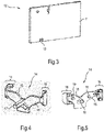
- Fig.3 shows a circuit board 11 of a light source carrier of the operating element 1 in the form of an LED circuit board 12 in a view obliquely from behind.
- the circuit board 11 has a bottom slit 13 for engagement with a lower step of the rib 5 .
- the printed circuit board 11 can be equipped with at least one LED and possibly with at least one associated electrical component (not illustrated).
- Fig.4 shows a light guide 14 in a view obliquely from the front.
- the light guide 14 is a transparent plastic part that can be produced, for example, as an injection molded part.
- the light guide 14 has wings 15 extending to the left and right in a mirror-symmetrical manner. The wings 15 are bent twice backwards at their end sections 16 by 90°.
- the light guide 14 also has a light guide section 17 protruding in the center at the front.
- Fig.5 shows the light guide 14 in a view obliquely from behind.
- a light-guiding section 18 goes backwards in the middle.
- a pin 19 protrudes to the rear, which is provided for engagement with a respective fixing hole 9 .
- Two further pin-shaped projections 20 protrude from the end sections 16 at the rear.
- Fig.6 shows a light guide 21 in a view obliquely from the front.
- the light guide 21 is a transparent plastic part that can be produced as an injection molded part.
- the light guide 21 has wings 22 extending to the left and right in a mirror-symmetrical manner. The wings 22 are bent backwards twice at their end sections 23 by 90°.
- the light guide 21 also has a light-guiding section 24 that protrudes centrally on the front side and has a different shape than the light-guiding section 17 .
- Fig.7 shows the light guide 21 in a view obliquely from behind.
- a light-guiding section 25 goes backwards in the middle.
- a pin 19 projects rearward from each of the wings 22 and is provided for engagement with a respective fixing hole 9 . No pin-shaped projections protrude from the rear of the end sections 16 here.
- Fig.8 shows the operating element 1 in an exploded view from diagonally behind.
- the light guide 14 and the adapter part 2 are joined together so that together they form a slide-in slot 26 (see Fig.9 ) for the LED circuit board 12, as indicated by the wide arrows.
- Fig.9 shows the assembled control element 1 in an oblique view from behind.
- the light guide 14 and the adapter part 2 form a slot 26 into which the LED circuit board 12 has been pushed from above.
- the front side of the LED circuit board 12 rests on vertical sections 27 of the steps of the ribs 5 and 6 and on the side edges 28 protruding from the support area 4 at the rear.
- the lower-lying step sections of the ribs 5, 6 also support the LED circuit board 12 downwards.
- the ribs 5 and 6 and the side edges 28 thus provide a rear support surface 5, 6, 28 for supporting the LED circuit board 12.
- the end sections 16 are bent backwards in such a way that they encompass the support area 4 in such a way that the insertion shaft 26 is formed by means of a gap between the support area 4 or the support surface 5 , 6 , 28 and the end sections 16 .
- the ribs 5, 6 also serve as spacers for the support area 4 relative to the LED circuit board 12 because of their gradation.
- the rib 5 engages in the slot 13 of the LED circuit board 12 in order to prevent lateral displacement.
- the protrusion 7 serves as a touch guard or barrier in the event that the LED board 12 and light guide 14 are not installed.
- the projection 7 can also be omitted.
- the locking tab 10 is provided for at least positive locking of the LED circuit board 12 in the slide-in slot 26 .
- the locking tab 10 is pushed in again when mounting on a technical support part (e.g. a panel support). This reduces the spring deflection during assembly and allows additional coverage in the final assembled state.
- the rear side of the light guide 14 rests on the front side of the recess 29 of the support area 4 , its position being fixed by the pins 19 engaging in the holes 9 .
- the light guide 14 covers the opening 8 at the front in such a way that the rear light-guiding section 18 protrudes through the opening 8 in the direction of the LED circuit board 12 .
- Light emitted forwards by the LEDs of the LED circuit board 12 is coupled into the rear fiber-optics section 18 at the front and is coupled out again from the front-side fiber-optics section 17 at the front. The light passes through the opening 8 within the light guide 14.
- the decoupled light can, for example, illuminate an inside of the rotary knob so that it can be illuminated from the inside or backlit.
- the light guide 21 can be used.
- the light guide 14 is used to illuminate a rotary knob used to set the temperature
- the light guide 21 can be used, for example, to illuminate a rotary knob used to set the function.
- only the appropriate light guide needs to be selected, while the adapter part 2 and the LED circuit board 12, for example, can remain the same.
- a numerical specification can also include exactly the specified number as well as a usual tolerance range, as long as this is not explicitly excluded.
Landscapes
- Engineering & Computer Science (AREA)
- Chemical & Material Sciences (AREA)
- Combustion & Propulsion (AREA)
- Mechanical Engineering (AREA)
- General Engineering & Computer Science (AREA)
- Rotary Switch, Piano Key Switch, And Lever Switch (AREA)
- Arrangement Of Elements, Cooling, Sealing, Or The Like Of Lighting Devices (AREA)
Description
- Die Erfindung betrifft ein Bedienelement für ein Haushaltsgerät, wobei das Bedienelement ein Adapterteil zur Anbindung eines Bedienelementkopfs sowie einen Lichtleiter aufweist und wobei das Adapterteil und der Lichtleiter miteinander gefügt sind und zusammen einen Einschubschacht für einen Lichtquellenträger bilden. Ein Haushaltsgerät weist mindestens ein solches Bedienelement auf. Die Erfindung ist insbesondere vorteilhaft anwendbar auf Bedienelemente für frontseitige Bedienblenden, insbesondere Ofen- oder Herdbedienblenden.
-
DE 10 2012 204 223 A1 offenbart ein Bedienelement für ein Haushaltsgerät, mit einem Bedienelementkopf, welcher drehbar in einer Trägerhülse angeordnet ist, und einem Schaltungsträger, der einem Sollwertgeber zugehörig ist, auf welchem Schaltungsträger elektrische Kontakte angeordnet sind, die mit elektrischen Kontakten eines Drehstellers des Sollwertgebers, der mit dem Bedienelementkopf gekoppelt ist, kontaktierbar sind, wobei der Drehsteller relativ zum Schaltungsträger abhängig von der Bewegung des Bedienelementkopfs bewegbar ist, und abhängig davon die Drehstellung des Bedienelementkopfs erfassbar ist, wobei zumindest eine Lichtquelle auf dem Schaltungsträger angeordnet ist, und benachbart zu der Lichtquelle ein zur Trägerhülse separater Lichtleiter angeordnet ist, in den das Licht der Lichtquelle einkoppelbar und ins Innere der Trägerhülse leitbar ist, wobei der Lichtleiter bereichsweise als Licht leitendes Befestigungselement ausgebildet ist. Die Erfindung betrifft auch eine Bedienvorrichtung mit einem derartigen Bedienelement. - Die
WO 2012/089506 A1 offenbart ein Haushaltsgerät mit einer aus Glas hergestellten Bedienblende, einer an der Bedienblende angeordneten kreisförmigen Öffnung, einem in der Öffnung angeordneten Knauf, einem an der Rückseite der Bedienblende befestigten Gehäuse, das sich von der Bedienblende aus nach innen erstreckt und den Knauf schützt, Lichtquellen-LEDs, die an der Rückwand des Gehäuses angeordnet sind, und einen Lichtleiter, der in dem Gehäuse angeordnet ist und der die Peripherie des zu beleuchtenden Knopfes bereitstellt. -
DE 200 1 0 428 U1 offenbart eine Anordnung zur Beleuchtung des Stellknopfes eines Eingabeaggregates mittels Durchlicht, wobei das Eingabeaggregat einen an einer Trennwand befestigten Drehschalter aufweist, dessen den Stellknopf tragende Stellwelle auf die Gegenseite der Trennwand durchgreift und wobei wenigstens eine auf der Seite des Drehschalters befindliche Lichtquelle vorgesehen ist, wobei ein Lichtleiter vorgesehen ist, an dem Lichtleiter eine dem zu durchleuchtenden Bereich des Stellknopfes entsprechende Lichtausleitfläche ausgebildet ist, der Lichtleiter stellknopfseitig an der Trennwand befestigt ist und der Lichtleiter durch die Trennwand auf die Lichtquelle durchgreift.DE 10 2005 015814 A1 offenbart ein Bedienelement nach dem Oberbegriff des Anspruchs 1. - Es ist die Aufgabe der vorliegenden Erfindung, die Nachteile des Standes der Technik zumindest teilweise zu überwinden und insbesondere ein besonders zuverlässig montierbares und preiswertes Bedienelement für ein Haushaltsgerät bereitzustellen. Diese Aufgabe wird gemäß den Merkmalen der unabhängigen Ansprüche gelöst. Bevorzugte Ausführungsformen sind insbesondere den abhängigen Ansprüchen entnehmbar.
- Dieses Bedienelement weist den Vorteil auf, dass der Lichtquellenträger nur montiert werden kann, wenn der Lichtleiter mit dem Adapterteil kombiniert worden ist. Es ergibt sich somit eine Zwangsläufigkeit in der Montage, durch die gewährleistet wird, dass der Lichtleiter immer montiert ist. Der Lichtleiter kann im Montageprozess nicht vergessen werden, so dass eine vorgegebene Ausleuchtqualität (z.B. in Bezug auf eine Gleichmäßigkeit) und Ausleuchthelligkeit zuverlässig eingehalten werden. Darüber hinaus lässt sich ein solches Bedienelement mit besonders wenigen Teilen kostengünstig herstellen.
- Das Aufnahmeteil und der Lichtleiter sind somit insbesondere getrennte Bauteile, die erst nachträglich miteinander verbunden werden.
- Das Haushaltsgerät ist insbesondere ein elektrisch betriebenes Haushaltsgerät. Das Haushaltsgerät kann ein Haushalts-Großgerät (z.B. ein Gargerät, ein Wäschepflegegerät, ein Kühlgerät, ein Spülgerät usw.) oder ein Haushalts-Kleingerät (z.B. eine Kaffeemaschine, ein Toaster usw.) sein. Ist das Haushaltsgerät ein Gargerät, kann es ein Ofen, ein Mikrowellengerät, ein Dampfgargerät, ein Kochfeld oder eine beliebige Kombination davon (beispielsweise ein Herd, ggf. mit Mikrowellen- und/oder Dampfgarfunktion) sein.
- Das Adapterteil ist insbesondere mit dem Bedienelementkopf mechanisch verbunden. Das Adapterteil kann den Bedienelementkopf halten. Das Adapterteil kann eine mechanische Bewegung des Bedienelementkopfs an einen entsprechenden Sensor übertragen. Das Adapterteil kann auch zur Befestigung des Bedienelements an einem technischen Trägerteil (z.B. an einer Bedienblende oder an einem Schalterträger bzw. Blendenträger) ausgerüstet sein. Das technische Trägerteil kann insbesondere eine Ofen-, Herd- oder Kochfeld-Bedienblende sein. Die Bedienblende kann eine frontseitige Blende sein.
- Der Bedienelementkopf ist zur Betätigung durch einen Nutzer vorgesehen, z.B. indem der Nutzer den Bedienelementkopf greift oder drückt.
- Der Lichtleiter dient zur inneren Führung von Licht, beispielsweise durch einen innen verspiegelten Hohlkanal oder durch innere Totalreflexion. Ein durch innere Totalreflexion lichtleitender Körper kann auch als TIR-Körper bezeichnet werden. Ein TIR-Körper kann aus transparentem Material wie Glas oder Kunststoff bestehen, z.B. aus Plexiglas.
- Mittels des Lichtleiters kann Licht, das von mindestens einer Lichtquelle des Lichtquellenträgers abgestrahlt wird, weitergeleitet werden, beispielweise zur Hinterleuchtung oder Innenbeleuchtung des Bedienelementkopfs und/oder eines den Bedienelementkopf umgebenden Leuchtelements (z.B. eines Leuchtrings o.ä.).
- Dass das Adapterteil und der Lichtleiter miteinander gefügt sind, kann insbesondere umfassen, dass diese Komponenten direkt miteinander verbunden sind, also ohne Zwischenstücke o.ä. Das Fügen kann ein formschlüssiges, kraftschlüssiges und/oder stoffschlüssiges Fügen umfassen.
- Der Einschubschacht ist dazu ausgebildet, dass ein Lichtquellenträger dort hinein einschiebbar oder einsteckbar ist. Der Lichtquellenträger kann in dem Einschubschacht formschlüssig, kraftschlüssig und/oder stoffschlüssig gehalten werden.
- Der Lichtquellenträger ist mit mindestens einer Lichtquelle bestückt. Die mindestens eine Lichtquelle kann mindestens eine LED oder mindestens eine Laserdiode sein. Der Lichtquellenträger kann eine Platine oder Leiterplatte oder z.B. auch ein plattenförmiges Keramiksubstrat aufweisen. Der Lichtquellenträger kann also insbesondere eine LED-Platine sein.
- Es ist eine Weiterbildung, dass, dass das Bedienelement den in den Einschubschacht eingesteckten oder aufgenommenen Lichtquellenträger aufweist. Von der mindestens einen Lichtquelle abgestrahltes Licht ist dann in den Lichtleiter einkoppelbar und wird innerhalb des Lichtleiters geführt. Das Licht kann insbesondere an einer Stelle wieder aus dem Lichtleiter ausgekoppelt werden, bei der es zumindest einen Teilbereich des Bedienelements hinterleuchtet.
- Der Anspruch 1 weiter offenbart, dass das Adapterteil einen Auflagebereich mit einer rückwärtigen Auflagefläche zur Auflage des Lichtquellenträgers aufweist, der Lichtleiter Bereiche ("Flügel") aufweist, die an einer vorderseitigen Auflagefläche des Auflagebereichs aufliegen, und die Flügel an ihren Endabschnitten rückwärtig umgebogen sind, so dass sie den Auflagebereich dergestalt umgreifen, dass der Einschubschacht mittels eines Spalts zwischen dem Auflagebereich und den Endabschnitten gebildet wird. Diese Ausgestaltung weist den Vorteil auf, dass sie sich besonders einfach montieren lässt, robust ist und den Einschubschacht mit geringen Toleranzen bilden kann. Die rückwärtige Auflagefläche und die Endbereiche können den Lichtquellenträger zumindest formschlüssig (d.h., nur formschlüssig oder formschlüssig und zusätzlich kraftschlüssig und/oder stoffschlüssig) in dem Einschubschacht halten.
- Unter einer rückwärtigen Auflagefläche kann insbesondere eine Auflagefläche verstanden werden, die bei frontaler Betrachtung von außen auf das eingebaute Bedienelement dem Betrachter abgewandt ist.
- Unter einem Flügel kann insbesondere ein Bereich des Lichtleiters verstanden werden, der sich bei frontaler Betrachtung seitlich oder lateral erstreckt, insbesondere nach links bzw. nach rechts. Der Flügel kann insbesondere ein länglicher Bereich sein. Die Flügel können insbesondere zwei Flügel sein. Sie können spiegelsymmetrisch ausgebildet sein. Die Flügel können auch als Arme bezeichnet werden.
- Ein Flügel kann sich insbesondere bis zu seinem Endabschnitt auf dem Auflagebereich bzw. auf dessen vorderseitiger Auflagefläche aufliegen. Der Adapter kann insbesondere eine Plattenform oder Scheibenform aufweisen, wobei eine erste Flachseite die vorderseitige Auflagefläche aufweist oder bildet und eine zweite Flachseite die rückseitige Auflagefläche aufweist oder bildet. Der Lichtleiter kann zum Teil in einer vorderseitigen Vertiefung des Adapterbereichs untergebracht sein, insbesondere in einer zumindest ungefähr komplementär geformten Vertiefung.
- Es ist eine Weiterbildung, dass die Flügel, insbesondere deren Endbereich, elastisch verformbar sind. Dadurch wird die Montage noch weiter vereinfacht. Ein weiterer Vorteil besteht darin, dass die Endabschnitte als rückfedernde Haltebereiche für den Lichtquellenträger dienen können, um diesen in einer Klemmpassung in dem Einschubschacht zu halten.
- Es ist eine Weiterbildung, dass das Adapterteil und der Lichtleiter aus Kunststoff bestehen. Insbesondere kann das Adapterteil aus einem nicht lichtleitenden Kunststoff bestehen und der Lichtleiter aus einem lichtleitenden, insbesondere transparenten Kunststoff bestehen.
- Es ist noch eine Ausgestaltung, dass der Auflagebereich eine Durchbrechung aufweist, die von dem Lichtleiter vorderseitig zumindest teilweise überdeckt ist und der Lichtleiter einen in rückwärtiger Richtung durch die Durchbrechung ragenden Lichtleitabschnitt zur Einkopplung des Lichts des Lichtquellenträgers aufweist. Dies ergibt den Vorteil, dass durch den rückwärtigen Lichtleitabschnitt Lichtverluste besonders gering gehalten werden können. Dort mit geringem Abstand zu der mindestens einen Lichtquelle eingekoppeltes Licht ist durch die Durchbrechung zur Vorderseite leitbar, von wo aus es in Richtung des Bedienelementkopfs o.ä. abstrahlbar ist.
- Es ist eine Weiterbildung, dass der Lichtleiter einen vorderseitig vorstehenden Lichtleitabschnitt aufweist. Dies ermöglicht es vorteilhafterweise, dass von dem Lichtleiter geführte Licht nahe an den Bedienelementkopf heranzuführen, um dort einen vorgegebenen Bereich mit hoher Helligkeit zu hinterleuchten. Der rückwärtig vorstehende Lichtleitabschnitt und der vorderseitig vorstehende Lichtleitabschnitt können insbesondere kollinear zueinander liegen.
- Es ist eine weitere Ausgestaltung, dass das Adapterteil einen rückwärtig vorstehenden, elastisch biegbaren Verriegelungsbereich zum zumindest formschlüssigen Verriegeln des Lichtquellenträgers in dem Einschubschacht aufweist. Dadurch kann ein ungewolltes Ausgleiten des Lichtquellenträgers aus dem Einschubschacht verhindert werden. Der Verriegelungsbereich kann als Rasthaken oder Verriegelungslasche ausgebildet sein.
- Es ist noch eine weitere Ausgestaltung, dass das Adapterteil, insbesondere dessen Auflagebereich, mindestens eine als Abstandshalter dienende Rippe aufweist. Die Rippe kann zumindest einen Teil der rückwärtigen Auflagefläche darstellen. Dadurch kann beispielsweise ein Abstand zu einem rückwärtigen Lichtleitbereich des Lichtleiters genau eingestellt werden. Auch wird so ein Luftspalt zwischen dem Lichtquellenträger und dem Adapterteil ermöglicht. Der Luftspalt kann zur Aufnahme von Lichtquellen und/oder anderen elektrischen und/oder elektronischen Bauelements dienen. Der Luftspalt kann auch zur Wärmeableitung von dem Lichtquellenträger durch Luftkonvektion dienen. Die rückwärtige Auflagefläche kann einen zur Auflage des Lichtquellenträgers dienenden Rand der Rippe umfassen.
- Es ist ferner eine Ausgestaltung, dass das Adapterteil mindestens eine Rippe zum Eingreifen in eine Aussparung des Lichtquellenträgers aufweist. Dadurch wird eine Sperrung gegen eine seitliche oder laterale Bewegung des Lichtquellenträgers erreicht. Die dazu verwendete mindestens eine Rippe kann die gleiche Rippe sein, die auch als Abstandshalter dient. Die Rippe kann insbesondere in diesem Fall gestuft geformt sein.
- Es ist auch eine Ausgestaltung, dass das Adapterteil mindestens einen als rückwärtige Begrenzung des Einschubschachts dienenden Vorsprung aufweist. Dieser Vorsprung kann vorteilhafterweise als Einschubhilfe dienen. Auch kann der Vorsprung dazu dienen, ein Durchbiegen des Leiterplattenträgers zu verhindern.
- Es ist außerdem eine Ausgestaltung, dass der Bedienelementkopf durch aus dem Lichtleiter auskoppelbares Licht innenbeleuchtbar ist. Der Bedienelementkopf kann dazu zumindest bereichsweise lichtdurchlässige Fenster, Löcher usw. aufweisen.
- Es ist zudem eine Ausgestaltung, dass der Bedienelementkopf ein Schalterknebel ist und das Adapterteil eine mit dem Schalterknebel verbundene Welle aufweist. Ein solches Bedienelement kann auch als Drehknopf oder Drehknebel bezeichnet werden.
- Die Aufgabe wird auch gelöst durch ein Haushaltsgerät, aufweisend mindestens ein Bedienelement wie oben besprochen, insbesondere eine Bedienblende mit mindestens einem Bedienelement wie oben besprochen. Das Haushaltsgerät kann analog zu dem Bedienelement ausgebildet werden und weist die gleichen Vorteile auf. Das Adapterteil kann z.B. an der Bedienblende befestigt sein, ggf. an einem zugehörigen Schaltträger.
- Es ist eine Ausgestaltung, dass das Adapterteil rückwärtig an der Bedienblende oder einem der Bedienblende zugeordneten technischen Trägerteil angebracht ist und der Bedienelementkopf vorderseitig an der Bedienblende angeordnet ist. Der Lichtleiter kann durch die Bedienblende ragen oder kann vollständig hinter der Bedienblende verbleiben. Bei einer Anordnung vollständig hinter der Bedienblende kann der Lichtleiter Licht durch ein Loch in der Bedienblende auf den Bedienelementkopf o.ä. strahlen.
- Die Bedienblende kann eine frontseitige Bedienblende sein.
- Die oben beschriebenen Eigenschaften, Merkmale und Vorteile dieser Erfindung sowie die Art und Weise, wie diese erreicht werden, werden klarer und deutlicher verständlich im Zusammenhang mit der folgenden schematischen Beschreibung eines Ausführungsbeispiels, das im Zusammenhang mit den Zeichnungen näher erläutert wird.
- Fig.1
- zeigt ein Adapterteil eines Bedienelements in einer Ansicht von schräg hinten;
- Fig.2
- zeigt das Adapterteil aus
Fig.1 in einer Ansicht von schräg vorne; - Fig.3
- zeigt eine Leiterplatte eines Lichtquellenträgers des Bedienelements in einer Ansicht von schräg hinten;
- Fig.4
- zeigt einen Lichtleiter gemäß dem ersten Ausführungsbeispiel in einer Ansicht von schräg vorne;
- Fig.5
- zeigt den Lichtleiter des Bedienelements gemäß dem ersten Ausführungsbeispiel in einer Ansicht von schräg hinten;
- Fig.6
- zeigt einen Lichtleiter gemäß einem zweiten Ausführungsbeispiel in einer Ansicht von schräg vorne;
- Fig.7
- zeigt den Lichtleiter des Bedienelements gemäß dem zweiten Ausführungsbeispiel in einer Ansicht von schräg hinten;
- Fig.8
- zeigt das Bedienelement in einer Explosionszeichnung von schräg hinten; und
- Fig.9
- zeigt in einer Ansicht von schräg hinten das zusammengesetzte Bedienelement.
-
Fig.1 zeigt eine Komponente eines Bedienelements 1 für ein Haushaltsgerät H, nämlich ein Adapterteil 2, in einer Ansicht von schräg hinten.Fig.2 zeigt das Adapterteil 2 in einer Ansicht von schräg vorne. - Das Adapterteil 2 ist mehrteilig aufgebaut und besteht aus Kunststoff. Das Adapterteil 2 wird im Folgenden anhand einer gezeigten typischen Einbaustellung beschrieben. Jedoch können das Adapterteil 2 und damit auch das Bedienelement 1 eine andere Ausrichtung im Raum aufweisen.
- Das Adapterteil 2 weist eine drehbare Welle 3 auf, die vorderseitig mit einem Bedienelementkopf in Form eines Drehschalters oder Drehknebels (o. Abb.) verbindbar ist. Die drehbare Welle 3 kann rückwärtig mit einem Drehwinkelsensor o.ä. (o. Abb.) verbunden sein.
- Das Adapterteil 2 weist oberhalb der Welle 3 einen Aufnahme- oder Auflagebereich 4 mit plattenförmiger Grundform auf. Von dem Auflagebereich 4 stehen rückwärtig zwei oberseitig gestufte Rippen 5 und 6 vor. Rückwärtig beabstandet zu dem Auflagebereich 4 steht von einem Wellengehäuse ein lappenartiger Vorsprung 7 hoch. Auch stehen seitlich der Rippen 5, 6 zwei Seitenränder 28 von dem Auflagebereich 4 vor. Diese stehen in rückwärtiger Richtung z.B. genauso weit vor wie vertikale Abschnitte 27 von Stufen der Rippen 5, 6.
- In dem Auflagebereich 4 befinden sich zudem ein Durchbruch 8 und zwei Fixierungslöcher 9. Von dem Auflagebereich 4 geht darüber hinaus eine elastisch biegbare Verriegelungslasche 10 in rückwärtige Richtung ab. Die Verriegelungslasche 10 befindet sich oberhalb der Rippen 5, 6 und des Durchbruchs 8.
- Vorderseitig ist in dem Auflagebereich 4 eine als vorderseitige Auflagefläche für einen Lichtleiter 14 (siehe
Fig.4 und Fig.5 ) dienende Vertiefung 29 vorhanden. -
Fig.3 zeigt eine Leiterplatte 11 eines in Form einer LED-Platine 12 vorliegenden Lichtquellenträgers des Bedienelements 1 in einer Ansicht von schräg hinten. Die Leiterplatte 11 weist einen unterseitigen Schlitz 13 zum Eingriff mit einer tieferen Stufe der Rippe 5 auf. - Vorderseitig kann die Leiterplatte 11 mit mindestens einer LED und ggf. mit mindestens einem zugehörigen elektrischen Bauelement bestückt sein (o. Abb.).
-
Fig.4 zeigt einen Lichtleiter 14 in einer Ansicht von schräg vorne. Der Lichtleiter 14 ist ein transparentes Kunststoffteil, das z.B. als Spritzgussteil herstellbar ist. Der Lichtleiter 14 weist spiegelsymmetrisch nach links und rechts abgehende Flügel 15 auf. Die Flügel 15 sind an ihren Endabschnitten 16 zweimal um 90° rückwärtig umgebogen. Der Lichtleiter 14 weist ferner einen vorderseitig mittig vorstehenden Lichtleitabschnitt 17 auf. -
Fig.5 zeigt den Lichtleiter 14 in einer Ansicht von schräg hinten. Mittig geht ein Lichtleitabschnitt 18 rückwärtig ab. Von den Flügeln 15 steht jeweils ein Zapfen 19 nach hinten vor, der zum Eingriff mit einem jeweiligen Fixierungsloch 9 vorgesehen ist. Von den Endabschnitten 16 stehen rückwärtig jeweils zwei weitere zapfenförmige Vorsprünge 20 vor. -
Fig.6 zeigt einen Lichtleiter 21 in einer Ansicht von schräg vorne. Der Lichtleiter 21 ist ein transparentes Kunststoffteil, das als Spritzgussteil herstellbar ist. Der Lichtleiter 21 weist spiegelsymmetrisch nach links und rechts abgehende Flügel 22 auf. Die Flügel 22 sind an ihren Endabschnitten 23 zweimal um 90° rückwärtig umgebogen. Der Lichtleiter 21 weist ferner einen vorderseitig mittig vorstehenden Lichtleitabschnitt 24 auf, der im Vergleich zu dem Lichtleitabschnitt 17 eine unterschiedliche Form aufweist. -
Fig.7 zeigt den Lichtleiter 21 in einer Ansicht von schräg hinten. Mittig geht ein Lichtleitabschnitt 25 rückwärtig ab. Von den Flügeln 22 steht jeweils ein Zapfen 19 nach hinten vor, der zum Eingriff mit einem jeweiligen Fixierungsloch 9 vorgesehen ist. Von den Endabschnitten 16 stehen hier rückwärtig keine zapfenförmigen Vorsprünge vor. -
Fig.8 zeigt das Bedienelement 1 in einer Explosionszeichnung von schräg hinten. Typischerweise werden zunächst der Lichtleiter 14 und das Adapterteil 2 miteinander gefugt, so dass sie zusammen einen Einschubschacht 26 (sieheFig.9 ) für die LED-Platine 12 bilden, wie durch die breiten Pfeile angedeutet. -
Fig.9 zeigt in einer Ansicht von schräg hinten das zusammengesetzte Bedienelement 1. Der Lichtleiter 14 und das Adapterteil 2 bilden einen Einschubschacht 26, in welchen die LED-Platine 12 von oben einschoben worden ist. - Die LED-Platine 12 liegt mit ihrer Vorderseite auf vertikalen Abschnitten 27 der Stufen der Rippen 5 und 6 sowie auf den rückwärtig von dem Auflagebereich 4 vorstehenden Seitenrändern 28 auf. Die tieferliegenden Stufenabschnitte der Rippen 5, 6 stützen die LED-Platine 12 zudem nach unten ab. Die Rippen 5 und 6 sowie die Seitenränder 28 stellen also eine rückwärtige Auflagefläche 5, 6, 28 zur Auflage der LED-Platine 12 bereit.
- Die Endabschnitte 16 sind so rückwärtig umgebogen, dass sie den Auflagebereich 4 dergestalt umgreifen, dass der Einschubschacht 26 mittels eines Spalts zwischen dem Auflagebereich 4 bzw. der Auflagefläche 5, 6, 28 und den Endabschnitten 16 gebildet wird. Dabei dienen die Rippen 5, 6 aufgrund ihrer Stufung auch als Abstandshalter des Auflagebereichs 4 gegenüber der LED-Platine 12. Die Rippe 5 greift in den Schlitz 13 der LED-Platine 12 ein, um eine seitliche Verschiebung zu verhindern. Der Vorsprung 7 dient als ein Berührschutz oder eine Barriere für den Fall, dass die LED-Platine 12 und der Lichtleiter 14 nicht eingebaut sind. Auf den Vorsprung 7 kann auch verzichtet werden.
- Zur zumindest formschlüssigen Verriegelung der LED-Platine 12 in dem Einschubschacht 26 ist die Verriegelungslasche 10 vorgesehen. Die Verriegelungslasche 10 wird beim Montieren auf einem technischen Trägerteil (z.B. einem Blendenträger) nochmals nachgedrückt. Dies reduziert den Federweg während der Montage und ermöglicht eine zusätzliche Überdeckung im endmontierten Zustand.
- Der Lichtleiter 14 liegt mit seiner Rückseite auf der Vorderseite der Vertiefung 29 des Auflagebereichs 4 auf, wobei seine Position durch Eingriff der Zapfen 19 in die Löcher 9 fixiert ist. Der Lichtleiter 14 überdeckt die Durchbrechung 8 vorderseitig so, dass der rückwärtige Lichtleitabschnitt 18 in Richtung der LED-Platine 12 durch die Durchbrechung 8 ragt. Nach vorne abgestrahltes Licht der LEDs der LED-Platine 12 wird stirnseitig in den rückwärtigen Lichtleitabschnitt 18 eingekoppelt und stirnseitig aus dem vorderseitigen Lichtleitabschnitt 17 wieder ausgekoppelt. Dabei durchläuft das Licht die Durchbrechung 8 innerhalb des Lichtleiters 14.
- Das ausgekoppelte Licht kann beispielsweise eine Innenseite des Drehknebels beleuchten, so dass dieser innenbeleuchtbar oder hinterleuchtbar ist.
- Selbstverständlich ist die vorliegende Erfindung nicht auf das gezeigte Ausführungsbeispiel beschränkt.
- So kann anstelle des Lichtleiters 14 der Lichtleiter 21 verwendet werden. Während beispielsweise der Lichtleiter 14 zur Beleuchtung eines zur Temperatureinstellung verwendeten Drehknebels eingesetzt wird, kann der Lichtleiter 21 z.B. zur Beleuchtung eines zur Funktionseinstellung verwendeten Drehknebels eingesetzt werden. Es braucht also vorteilhafterweise nur der passende Lichtleiter ausgewählt zu werden, während z.B. das Adapterteil 2 und die LED-Platine 12 gleich bleiben können.
- Allgemein kann unter "ein", "eine" usw. eine Einzahl oder eine Mehrzahl verstanden werden, insbesondere im Sinne von "mindestens ein" oder "ein oder mehrere" usw., solange dies nicht explizit ausgeschlossen ist, z.B. durch den Ausdruck "genau ein" usw.
- Auch kann eine Zahlenangabe genau die angegebene Zahl als auch einen üblichen Toleranzbereich umfassen, solange dies nicht explizit ausgeschlossen ist.
-
- 1
- Bedienelement
- 2
- Adapterteil
- 3
- Welle
- 4
- Auflagebereich
- 5
- Rippe
- 6
- Rippe
- 7
- Vorsprung
- 8
- Durchbruch
- 9
- Fixierungsloch
- 10
- Verriegelungslasche
- 11
- Leiterplatte
- 12
- LED-Platine
- 13
- Schlitz
- 14
- Lichtleiter
- 15
- Flügel
- 16
- Endabschnitt
- 17
- Lichtleitabschnitt
- 18
- Lichtleitabschnitt
- 19
- Zapfen
- 20
- Zapfenförmiger Vorsprung
- 21
- Lichtleiter
- 22
- Flügel
- 23
- Endabschnitt
- 24
- Lichtleitabschnitt
- 25
- Lichtleitabschnitt
- 26
- Einschubschacht
- 27
- Vertikaler Stufenabschnitt
- 28
- Seitenrand
- 29
- Vertiefung
- H
- Haushaltsgerät
Claims (10)
- Bedienelement (1) für ein Haushaltsgerät (H), aufweisend ein Adapterteil (2) zur Anbindung eines Bedienelementkopfs und aufweisend einen Lichtleiter (14; 21), dadurch gekennzeichnet, dass- das Adapterteil (2) und der Lichtleiter (14; 21) miteinander gefügt sind und zusammen einen Einschubschacht (26) für einen Lichtquellenträger (12) bilden,- das Adapterteil (2) einen Auflagebereich (4) mit einer rückwärtigen Auflagefläche (5, 6, 28) zur Auflage des Lichtquellenträgers (12) aufweist,- der Lichtleiter (14; 21) Flügel (15; 22) aufweist, die an einer vorderseitigen Auflagefläche (29) des Auflagebereichs (4) aufliegen,- die Flügel (15; 22) an ihren Endabschnitten (16; 23) rückwärtig umgebogen sind, so dass sie den Auflagebereich (4) dergestalt umgreifen, dass- der Einschubschacht (26) mittels eines Spalts zwischen dem Auflagebereich (4) und den Endabschnitten (16; 23) gebildet wird.
- Bedienelement (1) nach Anspruch 1, dadurch gekennzeichnet, dass- der Auflagebereich (4) eine Durchbrechung (8) aufweist, die von dem Lichtleiter (14; 21) vorderseitig überdeckt ist,- der Lichtleiter (14; 21) einen in rückwärtiger Richtung durch die Durchbrechung (8) ragenden Lichtleitabschnitt (18; 25) zur Einkopplung des Lichts des Lichtquellenträgers (12) aufweist und- der Lichtleiter (14; 21) einen vorderseitig vorstehenden Lichtleitabschnitt (17; 24) aufweist.
- Bedienelement (1) nach einem der vorhergehenden Ansprüche, dadurch gekennzeichnet, dass das Adapterteil (2) einen rückwärtig vorstehenden, elastisch biegbaren Verriegelungsbereich (10) zum zumindest formschlüssigen Verriegeln des Lichtquellenträgers (12) in dem Einschubschacht aufweist.
- Bedienelement (1) nach einem der vorhergehenden Ansprüche, dadurch gekennzeichnet, dass das Adapterteil (2) mindestens eine als Abstandshalter gegenüber dem Lichtquellenträger (12) dienende Rippe (5, 6) aufweist.
- Bedienelement (1) nach einem der vorhergehenden Ansprüche, dadurch gekennzeichnet, dass das Adapterteil (2) mindestens eine Rippe (5) zum Eingreifen in eine Aussparung (13) des Lichtquellenträgers (12) aufweist.
- Bedienelement (1) nach einem der vorhergehenden Ansprüche, dadurch gekennzeichnet, dass das Adapterteil (2) mindestens einen als rückwärtige Begrenzung des Einschubschachts (26) dienenden Vorsprung aufweist.
- Bedienelement (1) nach einem der vorhergehenden Ansprüche, dadurch gekennzeichnet, dass der Lichtleiter (14; 21) konfiguriert ist, durch aus dem Lichtleiter (14; 21) auskoppelbares Licht den Bedienelementkopf von innen zu beleuchten.
- Bedienelement (1) nach einem der vorhergehenden Ansprüche, dadurch gekennzeichnet, dass das Adapterteil (2) eine Welle (3) aufweist, die ausgebildet ist, mit einem Bedienelementkopf in Form eines Schalterknebels verbindbar zu sein.
- Haushaltsgerät (H), aufweisend eine Bedienblende mit mindestens einem Bedienelement (1) nach einem der vorhergehenden Ansprüche.
- Haushaltsgerät (H) nach Anspruch 9, dadurch gekennzeichnet, dass das Haushaltsgerät (H) einen Bedienelementkopf aufweist und das Adapterteil (2) rückwärtig an der Bedienblende angebracht ist und der Bedienelementkopf vorderseitig an der Bedienblende angeordnet ist.
Applications Claiming Priority (1)
| Application Number | Priority Date | Filing Date | Title |
|---|---|---|---|
| DE102016224740.9A DE102016224740A1 (de) | 2016-12-12 | 2016-12-12 | Bedienelement für ein Haushaltsgerät |
Publications (2)
| Publication Number | Publication Date |
|---|---|
| EP3333869A1 EP3333869A1 (de) | 2018-06-13 |
| EP3333869B1 true EP3333869B1 (de) | 2022-10-19 |
Family
ID=60484143
Family Applications (1)
| Application Number | Title | Priority Date | Filing Date |
|---|---|---|---|
| EP17203487.8A Active EP3333869B1 (de) | 2016-12-12 | 2017-11-24 | Bedienelement für ein haushaltsgerät |
Country Status (3)
| Country | Link |
|---|---|
| EP (1) | EP3333869B1 (de) |
| DE (1) | DE102016224740A1 (de) |
| PL (1) | PL3333869T3 (de) |
Citations (1)
| Publication number | Priority date | Publication date | Assignee | Title |
|---|---|---|---|---|
| DE102005015814A1 (de) * | 2005-04-06 | 2006-10-12 | Siemens Ag Österreich | Formteil als optischer Lichtleiter |
Family Cites Families (7)
| Publication number | Priority date | Publication date | Assignee | Title |
|---|---|---|---|---|
| DE19712294C2 (de) * | 1997-03-24 | 1999-08-12 | Preh Elektro Feinmechanik | Drehwiderstand |
| JP3649637B2 (ja) * | 2000-02-10 | 2005-05-18 | アルプス電気株式会社 | 電子機器の照光構造 |
| DE20010428U1 (de) * | 2000-06-09 | 2000-08-17 | Mannesmann VDO AG, 60388 Frankfurt | Anordnung zur Beleuchtung des Stellknopfes eines Eingabeaggregates mittels Durchlicht |
| DE102008061943B3 (de) * | 2008-12-12 | 2009-12-10 | Preh Gmbh | Bedienelement für Kraftfahrzeug |
| US8979289B2 (en) | 2010-12-30 | 2015-03-17 | Arcelik Anonim Sirketi | Illuminated knob for household appliance |
| JP5789539B2 (ja) * | 2012-02-15 | 2015-10-07 | バイエリッシェ モートーレン ウエルケ アクチエンゲゼルシャフトBayerische Motoren Werke Aktiengesellschaft | 車載用レバースイッチ装置 |
| DE102012204223A1 (de) | 2012-03-16 | 2013-09-19 | BSH Bosch und Siemens Hausgeräte GmbH | Bedienelement für ein Haushaltsgerät sowie Bedienvorrichtung mit zumindest einem derartigen Bedienelement |
-
2016
- 2016-12-12 DE DE102016224740.9A patent/DE102016224740A1/de not_active Withdrawn
-
2017
- 2017-11-24 PL PL17203487.8T patent/PL3333869T3/pl unknown
- 2017-11-24 EP EP17203487.8A patent/EP3333869B1/de active Active
Patent Citations (1)
| Publication number | Priority date | Publication date | Assignee | Title |
|---|---|---|---|---|
| DE102005015814A1 (de) * | 2005-04-06 | 2006-10-12 | Siemens Ag Österreich | Formteil als optischer Lichtleiter |
Also Published As
| Publication number | Publication date |
|---|---|
| DE102016224740A1 (de) | 2018-06-14 |
| PL3333869T3 (pl) | 2023-01-09 |
| EP3333869A1 (de) | 2018-06-13 |
Similar Documents
| Publication | Publication Date | Title |
|---|---|---|
| DE102016101008B4 (de) | Kochgerät | |
| DE102006041797B4 (de) | Tasten- und Hohllichtleitermechanismus sowie entsprechende Anordnung | |
| DE102007044393B3 (de) | Kapazitiver Annäherungs- und/oder Berührungsschalter | |
| EP2452434A1 (de) | Bedieneinrichtung für ein elektrogerät | |
| EP3170044B1 (de) | Anzeigevorrichtung und haushaltsgerät mit einer solchen anzeigevorrichtung | |
| EP1162638B1 (de) | Anordnung zur Beleuchtung des Stellknopfes eines Eingabeaggregates mittels Durchlicht | |
| DE202015104575U1 (de) | Haushaltsgerät und Haushaltsgeräteleuchte | |
| DE102018111092A1 (de) | Beleuchtungsvorrichtung für ein Gargerät mit einem Lichtleiter | |
| DE102014221784A1 (de) | Haushaltsgerät mit einer Eingabevorrichtung und einer Kodiervorrichtung | |
| EP3170374A1 (de) | Elektronische benutzerschnittstelle mit einer separaten steuerplatine und haushaltsgerät mit einer solchen benutzerschnittstelle | |
| EP2348638B1 (de) | Kapazitiver Berührungs- und/oder Annäherungsschalter | |
| DE69909158T2 (de) | Bedienblendeneinheit für ein Haushaltsgerät | |
| DE19737524A1 (de) | Hausgerät mit einem Gehäuseelement | |
| EP2993959B1 (de) | Haushaltsgerät | |
| EP1728026B2 (de) | Bedienblende für ein haushaltskältegerät | |
| EP3879547B1 (de) | Elektrisches installationsgerät mit integrierter beleuchtung | |
| EP3333869A1 (de) | Bedienelement für ein haushaltsgerät | |
| EP2420607B1 (de) | Blende einer Bedieneinheit für ein Haushaltsgerät, Bedieneinheit für ein Haushaltsgerät und Haushaltsgerät | |
| DE10155126B4 (de) | Optischer Signalgeber, insbesondere in der Bedienblende eines Haushaltsgroßgerätes | |
| EP3338027B1 (de) | Bedienvorrichtung für ein haushaltsgerät mit einem distanzelement sowie haushaltsgerät mit einer bedienvorrichtung | |
| EP2184746B1 (de) | Elektromechanisches Einstellgerät mit einer Drehachse | |
| DE102015208195A1 (de) | Kochfeld mit mindestens einer Halbleiterlichtquelle und Lichtstreukörper | |
| DE102012204223A1 (de) | Bedienelement für ein Haushaltsgerät sowie Bedienvorrichtung mit zumindest einem derartigen Bedienelement | |
| EP2184728B1 (de) | Anzeigevorrichtung | |
| DE102004044544A1 (de) | Vorrichtung zur Beleuchtung der Bedienungsblende einer Waschmaschine über das Elektronikgehäuse |
Legal Events
| Date | Code | Title | Description |
|---|---|---|---|
| PUAI | Public reference made under article 153(3) epc to a published international application that has entered the european phase |
Free format text: ORIGINAL CODE: 0009012 |
|
| STAA | Information on the status of an ep patent application or granted ep patent |
Free format text: STATUS: THE APPLICATION HAS BEEN PUBLISHED |
|
| AK | Designated contracting states |
Kind code of ref document: A1 Designated state(s): AL AT BE BG CH CY CZ DE DK EE ES FI FR GB GR HR HU IE IS IT LI LT LU LV MC MK MT NL NO PL PT RO RS SE SI SK SM TR |
|
| AX | Request for extension of the european patent |
Extension state: BA ME |
|
| STAA | Information on the status of an ep patent application or granted ep patent |
Free format text: STATUS: REQUEST FOR EXAMINATION WAS MADE |
|
| 17P | Request for examination filed |
Effective date: 20181213 |
|
| RBV | Designated contracting states (corrected) |
Designated state(s): AL AT BE BG CH CY CZ DE DK EE ES FI FR GB GR HR HU IE IS IT LI LT LU LV MC MK MT NL NO PL PT RO RS SE SI SK SM TR |
|
| STAA | Information on the status of an ep patent application or granted ep patent |
Free format text: STATUS: EXAMINATION IS IN PROGRESS |
|
| RIC1 | Information provided on ipc code assigned before grant |
Ipc: F24C 7/08 20060101ALI20191108BHEP Ipc: H01H 19/02 20060101AFI20191108BHEP |
|
| 17Q | First examination report despatched |
Effective date: 20191129 |
|
| GRAP | Despatch of communication of intention to grant a patent |
Free format text: ORIGINAL CODE: EPIDOSNIGR1 |
|
| STAA | Information on the status of an ep patent application or granted ep patent |
Free format text: STATUS: GRANT OF PATENT IS INTENDED |
|
| INTG | Intention to grant announced |
Effective date: 20220613 |
|
| GRAS | Grant fee paid |
Free format text: ORIGINAL CODE: EPIDOSNIGR3 |
|
| GRAA | (expected) grant |
Free format text: ORIGINAL CODE: 0009210 |
|
| STAA | Information on the status of an ep patent application or granted ep patent |
Free format text: STATUS: THE PATENT HAS BEEN GRANTED |
|
| AK | Designated contracting states |
Kind code of ref document: B1 Designated state(s): AL AT BE BG CH CY CZ DE DK EE ES FI FR GB GR HR HU IE IS IT LI LT LU LV MC MK MT NL NO PL PT RO RS SE SI SK SM TR |
|
| REG | Reference to a national code |
Ref country code: GB Ref legal event code: FG4D Free format text: NOT ENGLISH |
|
| REG | Reference to a national code |
Ref country code: CH Ref legal event code: EP |
|
| REG | Reference to a national code |
Ref country code: DE Ref legal event code: R096 Ref document number: 502017013969 Country of ref document: DE |
|
| REG | Reference to a national code |
Ref country code: IE Ref legal event code: FG4D Free format text: LANGUAGE OF EP DOCUMENT: GERMAN |
|
| REG | Reference to a national code |
Ref country code: AT Ref legal event code: REF Ref document number: 1526086 Country of ref document: AT Kind code of ref document: T Effective date: 20221115 |
|
| REG | Reference to a national code |
Ref country code: LT Ref legal event code: MG9D |
|
| REG | Reference to a national code |
Ref country code: NL Ref legal event code: MP Effective date: 20221019 |
|
| PG25 | Lapsed in a contracting state [announced via postgrant information from national office to epo] |
Ref country code: NL Free format text: LAPSE BECAUSE OF FAILURE TO SUBMIT A TRANSLATION OF THE DESCRIPTION OR TO PAY THE FEE WITHIN THE PRESCRIBED TIME-LIMIT Effective date: 20221019 |
|
| PG25 | Lapsed in a contracting state [announced via postgrant information from national office to epo] |
Ref country code: SE Free format text: LAPSE BECAUSE OF FAILURE TO SUBMIT A TRANSLATION OF THE DESCRIPTION OR TO PAY THE FEE WITHIN THE PRESCRIBED TIME-LIMIT Effective date: 20221019 Ref country code: PT Free format text: LAPSE BECAUSE OF FAILURE TO SUBMIT A TRANSLATION OF THE DESCRIPTION OR TO PAY THE FEE WITHIN THE PRESCRIBED TIME-LIMIT Effective date: 20230220 Ref country code: NO Free format text: LAPSE BECAUSE OF FAILURE TO SUBMIT A TRANSLATION OF THE DESCRIPTION OR TO PAY THE FEE WITHIN THE PRESCRIBED TIME-LIMIT Effective date: 20230119 Ref country code: LT Free format text: LAPSE BECAUSE OF FAILURE TO SUBMIT A TRANSLATION OF THE DESCRIPTION OR TO PAY THE FEE WITHIN THE PRESCRIBED TIME-LIMIT Effective date: 20221019 Ref country code: FI Free format text: LAPSE BECAUSE OF FAILURE TO SUBMIT A TRANSLATION OF THE DESCRIPTION OR TO PAY THE FEE WITHIN THE PRESCRIBED TIME-LIMIT Effective date: 20221019 Ref country code: ES Free format text: LAPSE BECAUSE OF FAILURE TO SUBMIT A TRANSLATION OF THE DESCRIPTION OR TO PAY THE FEE WITHIN THE PRESCRIBED TIME-LIMIT Effective date: 20221019 |
|
| PG25 | Lapsed in a contracting state [announced via postgrant information from national office to epo] |
Ref country code: RS Free format text: LAPSE BECAUSE OF FAILURE TO SUBMIT A TRANSLATION OF THE DESCRIPTION OR TO PAY THE FEE WITHIN THE PRESCRIBED TIME-LIMIT Effective date: 20221019 Ref country code: LV Free format text: LAPSE BECAUSE OF FAILURE TO SUBMIT A TRANSLATION OF THE DESCRIPTION OR TO PAY THE FEE WITHIN THE PRESCRIBED TIME-LIMIT Effective date: 20221019 Ref country code: IS Free format text: LAPSE BECAUSE OF FAILURE TO SUBMIT A TRANSLATION OF THE DESCRIPTION OR TO PAY THE FEE WITHIN THE PRESCRIBED TIME-LIMIT Effective date: 20230219 Ref country code: HR Free format text: LAPSE BECAUSE OF FAILURE TO SUBMIT A TRANSLATION OF THE DESCRIPTION OR TO PAY THE FEE WITHIN THE PRESCRIBED TIME-LIMIT Effective date: 20221019 Ref country code: GR Free format text: LAPSE BECAUSE OF FAILURE TO SUBMIT A TRANSLATION OF THE DESCRIPTION OR TO PAY THE FEE WITHIN THE PRESCRIBED TIME-LIMIT Effective date: 20230120 |
|
| REG | Reference to a national code |
Ref country code: CH Ref legal event code: PL |
|
| REG | Reference to a national code |
Ref country code: DE Ref legal event code: R097 Ref document number: 502017013969 Country of ref document: DE |
|
| REG | Reference to a national code |
Ref country code: BE Ref legal event code: MM Effective date: 20221130 |
|
| PG25 | Lapsed in a contracting state [announced via postgrant information from national office to epo] |
Ref country code: SM Free format text: LAPSE BECAUSE OF FAILURE TO SUBMIT A TRANSLATION OF THE DESCRIPTION OR TO PAY THE FEE WITHIN THE PRESCRIBED TIME-LIMIT Effective date: 20221019 Ref country code: RO Free format text: LAPSE BECAUSE OF FAILURE TO SUBMIT A TRANSLATION OF THE DESCRIPTION OR TO PAY THE FEE WITHIN THE PRESCRIBED TIME-LIMIT Effective date: 20221019 Ref country code: MC Free format text: LAPSE BECAUSE OF FAILURE TO SUBMIT A TRANSLATION OF THE DESCRIPTION OR TO PAY THE FEE WITHIN THE PRESCRIBED TIME-LIMIT Effective date: 20221019 Ref country code: LI Free format text: LAPSE BECAUSE OF NON-PAYMENT OF DUE FEES Effective date: 20221130 Ref country code: EE Free format text: LAPSE BECAUSE OF FAILURE TO SUBMIT A TRANSLATION OF THE DESCRIPTION OR TO PAY THE FEE WITHIN THE PRESCRIBED TIME-LIMIT Effective date: 20221019 Ref country code: DK Free format text: LAPSE BECAUSE OF FAILURE TO SUBMIT A TRANSLATION OF THE DESCRIPTION OR TO PAY THE FEE WITHIN THE PRESCRIBED TIME-LIMIT Effective date: 20221019 Ref country code: CZ Free format text: LAPSE BECAUSE OF FAILURE TO SUBMIT A TRANSLATION OF THE DESCRIPTION OR TO PAY THE FEE WITHIN THE PRESCRIBED TIME-LIMIT Effective date: 20221019 Ref country code: CH Free format text: LAPSE BECAUSE OF NON-PAYMENT OF DUE FEES Effective date: 20221130 |
|
| PLBE | No opposition filed within time limit |
Free format text: ORIGINAL CODE: 0009261 |
|
| STAA | Information on the status of an ep patent application or granted ep patent |
Free format text: STATUS: NO OPPOSITION FILED WITHIN TIME LIMIT |
|
| PG25 | Lapsed in a contracting state [announced via postgrant information from national office to epo] |
Ref country code: SK Free format text: LAPSE BECAUSE OF FAILURE TO SUBMIT A TRANSLATION OF THE DESCRIPTION OR TO PAY THE FEE WITHIN THE PRESCRIBED TIME-LIMIT Effective date: 20221019 Ref country code: LU Free format text: LAPSE BECAUSE OF NON-PAYMENT OF DUE FEES Effective date: 20221124 Ref country code: AL Free format text: LAPSE BECAUSE OF FAILURE TO SUBMIT A TRANSLATION OF THE DESCRIPTION OR TO PAY THE FEE WITHIN THE PRESCRIBED TIME-LIMIT Effective date: 20221019 |
|
| 26N | No opposition filed |
Effective date: 20230720 |
|
| PG25 | Lapsed in a contracting state [announced via postgrant information from national office to epo] |
Ref country code: IE Free format text: LAPSE BECAUSE OF NON-PAYMENT OF DUE FEES Effective date: 20221124 |
|
| PG25 | Lapsed in a contracting state [announced via postgrant information from national office to epo] |
Ref country code: SI Free format text: LAPSE BECAUSE OF FAILURE TO SUBMIT A TRANSLATION OF THE DESCRIPTION OR TO PAY THE FEE WITHIN THE PRESCRIBED TIME-LIMIT Effective date: 20221019 Ref country code: FR Free format text: LAPSE BECAUSE OF NON-PAYMENT OF DUE FEES Effective date: 20221219 Ref country code: BE Free format text: LAPSE BECAUSE OF NON-PAYMENT OF DUE FEES Effective date: 20221130 |
|
| REG | Reference to a national code |
Ref country code: AT Ref legal event code: MM01 Ref document number: 1526086 Country of ref document: AT Kind code of ref document: T Effective date: 20221124 |
|
| PG25 | Lapsed in a contracting state [announced via postgrant information from national office to epo] |
Ref country code: AT Free format text: LAPSE BECAUSE OF NON-PAYMENT OF DUE FEES Effective date: 20221124 |
|
| PG25 | Lapsed in a contracting state [announced via postgrant information from national office to epo] |
Ref country code: HU Free format text: LAPSE BECAUSE OF FAILURE TO SUBMIT A TRANSLATION OF THE DESCRIPTION OR TO PAY THE FEE WITHIN THE PRESCRIBED TIME-LIMIT; INVALID AB INITIO Effective date: 20171124 |
|
| PG25 | Lapsed in a contracting state [announced via postgrant information from national office to epo] |
Ref country code: CY Free format text: LAPSE BECAUSE OF FAILURE TO SUBMIT A TRANSLATION OF THE DESCRIPTION OR TO PAY THE FEE WITHIN THE PRESCRIBED TIME-LIMIT Effective date: 20221019 |
|
| PG25 | Lapsed in a contracting state [announced via postgrant information from national office to epo] |
Ref country code: MK Free format text: LAPSE BECAUSE OF FAILURE TO SUBMIT A TRANSLATION OF THE DESCRIPTION OR TO PAY THE FEE WITHIN THE PRESCRIBED TIME-LIMIT Effective date: 20221019 Ref country code: IT Free format text: LAPSE BECAUSE OF FAILURE TO SUBMIT A TRANSLATION OF THE DESCRIPTION OR TO PAY THE FEE WITHIN THE PRESCRIBED TIME-LIMIT Effective date: 20221019 |
|
| PG25 | Lapsed in a contracting state [announced via postgrant information from national office to epo] |
Ref country code: BG Free format text: LAPSE BECAUSE OF FAILURE TO SUBMIT A TRANSLATION OF THE DESCRIPTION OR TO PAY THE FEE WITHIN THE PRESCRIBED TIME-LIMIT Effective date: 20221019 |
|
| PG25 | Lapsed in a contracting state [announced via postgrant information from national office to epo] |
Ref country code: MT Free format text: LAPSE BECAUSE OF FAILURE TO SUBMIT A TRANSLATION OF THE DESCRIPTION OR TO PAY THE FEE WITHIN THE PRESCRIBED TIME-LIMIT Effective date: 20221019 |
|
| PGFP | Annual fee paid to national office [announced via postgrant information from national office to epo] |
Ref country code: DE Payment date: 20251130 Year of fee payment: 9 |
|
| PGFP | Annual fee paid to national office [announced via postgrant information from national office to epo] |
Ref country code: GB Payment date: 20251120 Year of fee payment: 9 |
|
| PGFP | Annual fee paid to national office [announced via postgrant information from national office to epo] |
Ref country code: TR Payment date: 20251118 Year of fee payment: 9 |
|
| PGFP | Annual fee paid to national office [announced via postgrant information from national office to epo] |
Ref country code: PL Payment date: 20251113 Year of fee payment: 9 |