EP3333446B1 - Valve structure for buffer - Google Patents
Valve structure for buffer Download PDFInfo
- Publication number
- EP3333446B1 EP3333446B1 EP16835029.6A EP16835029A EP3333446B1 EP 3333446 B1 EP3333446 B1 EP 3333446B1 EP 16835029 A EP16835029 A EP 16835029A EP 3333446 B1 EP3333446 B1 EP 3333446B1
- Authority
- EP
- European Patent Office
- Prior art keywords
- valve
- communication passage
- seat part
- plate
- plate valve
- Prior art date
- Legal status (The legal status is an assumption and is not a legal conclusion. Google has not performed a legal analysis and makes no representation as to the accuracy of the status listed.)
- Active
Links
- 238000004891 communication Methods 0.000 claims description 79
- 230000002093 peripheral effect Effects 0.000 claims description 48
- 239000006096 absorbing agent Substances 0.000 claims description 42
- 230000035939 shock Effects 0.000 claims description 42
- 230000005540 biological transmission Effects 0.000 claims description 23
- 125000006850 spacer group Chemical group 0.000 claims description 6
- 238000005192 partition Methods 0.000 claims description 4
- 238000013016 damping Methods 0.000 description 77
- 239000010720 hydraulic oil Substances 0.000 description 34
- 230000008602 contraction Effects 0.000 description 4
- 230000007423 decrease Effects 0.000 description 3
- 230000003247 decreasing effect Effects 0.000 description 3
- 238000007667 floating Methods 0.000 description 2
- 239000007788 liquid Substances 0.000 description 2
- 230000006835 compression Effects 0.000 description 1
- 238000007906 compression Methods 0.000 description 1
- 230000001419 dependent effect Effects 0.000 description 1
- 230000000694 effects Effects 0.000 description 1
- 239000012530 fluid Substances 0.000 description 1
- 238000000034 method Methods 0.000 description 1
- 239000003921 oil Substances 0.000 description 1
- 238000007789 sealing Methods 0.000 description 1
- XLYOFNOQVPJJNP-UHFFFAOYSA-N water Substances O XLYOFNOQVPJJNP-UHFFFAOYSA-N 0.000 description 1
- 238000003466 welding Methods 0.000 description 1
Images


Classifications
-
- F—MECHANICAL ENGINEERING; LIGHTING; HEATING; WEAPONS; BLASTING
- F16—ENGINEERING ELEMENTS AND UNITS; GENERAL MEASURES FOR PRODUCING AND MAINTAINING EFFECTIVE FUNCTIONING OF MACHINES OR INSTALLATIONS; THERMAL INSULATION IN GENERAL
- F16F—SPRINGS; SHOCK-ABSORBERS; MEANS FOR DAMPING VIBRATION
- F16F9/00—Springs, vibration-dampers, shock-absorbers, or similarly-constructed movement-dampers using a fluid or the equivalent as damping medium
- F16F9/32—Details
- F16F9/34—Special valve constructions; Shape or construction of throttling passages
- F16F9/348—Throttling passages in the form of annular discs or other plate-like elements which may or may not have a spring action, operating in opposite directions or singly, e.g. annular discs positioned on top of the valve or piston body
- F16F9/3484—Throttling passages in the form of annular discs or other plate-like elements which may or may not have a spring action, operating in opposite directions or singly, e.g. annular discs positioned on top of the valve or piston body characterised by features of the annular discs per se, singularly or in combination
-
- F—MECHANICAL ENGINEERING; LIGHTING; HEATING; WEAPONS; BLASTING
- F16—ENGINEERING ELEMENTS AND UNITS; GENERAL MEASURES FOR PRODUCING AND MAINTAINING EFFECTIVE FUNCTIONING OF MACHINES OR INSTALLATIONS; THERMAL INSULATION IN GENERAL
- F16F—SPRINGS; SHOCK-ABSORBERS; MEANS FOR DAMPING VIBRATION
- F16F9/00—Springs, vibration-dampers, shock-absorbers, or similarly-constructed movement-dampers using a fluid or the equivalent as damping medium
- F16F9/32—Details
- F16F9/34—Special valve constructions; Shape or construction of throttling passages
- F16F9/348—Throttling passages in the form of annular discs or other plate-like elements which may or may not have a spring action, operating in opposite directions or singly, e.g. annular discs positioned on top of the valve or piston body
- F16F9/3488—Throttling passages in the form of annular discs or other plate-like elements which may or may not have a spring action, operating in opposite directions or singly, e.g. annular discs positioned on top of the valve or piston body characterised by features intended to affect valve bias or pre-stress
-
- F—MECHANICAL ENGINEERING; LIGHTING; HEATING; WEAPONS; BLASTING
- F16—ENGINEERING ELEMENTS AND UNITS; GENERAL MEASURES FOR PRODUCING AND MAINTAINING EFFECTIVE FUNCTIONING OF MACHINES OR INSTALLATIONS; THERMAL INSULATION IN GENERAL
- F16F—SPRINGS; SHOCK-ABSORBERS; MEANS FOR DAMPING VIBRATION
- F16F9/00—Springs, vibration-dampers, shock-absorbers, or similarly-constructed movement-dampers using a fluid or the equivalent as damping medium
- F16F9/32—Details
- F16F9/34—Special valve constructions; Shape or construction of throttling passages
- F16F9/348—Throttling passages in the form of annular discs or other plate-like elements which may or may not have a spring action, operating in opposite directions or singly, e.g. annular discs positioned on top of the valve or piston body
- F16F9/3485—Throttling passages in the form of annular discs or other plate-like elements which may or may not have a spring action, operating in opposite directions or singly, e.g. annular discs positioned on top of the valve or piston body characterised by features of supporting elements intended to guide or limit the movement of the annular discs
-
- F—MECHANICAL ENGINEERING; LIGHTING; HEATING; WEAPONS; BLASTING
- F16—ENGINEERING ELEMENTS AND UNITS; GENERAL MEASURES FOR PRODUCING AND MAINTAINING EFFECTIVE FUNCTIONING OF MACHINES OR INSTALLATIONS; THERMAL INSULATION IN GENERAL
- F16F—SPRINGS; SHOCK-ABSORBERS; MEANS FOR DAMPING VIBRATION
- F16F9/00—Springs, vibration-dampers, shock-absorbers, or similarly-constructed movement-dampers using a fluid or the equivalent as damping medium
- F16F9/32—Details
- F16F9/50—Special means providing automatic damping adjustment, i.e. self-adjustment of damping by particular sliding movements of a valve element, other than flexions or displacement of valve discs; Special means providing self-adjustment of spring characteristics
- F16F9/512—Means responsive to load action, i.e. static load on the damper or dynamic fluid pressure changes in the damper, e.g. due to changes in velocity
- F16F9/5126—Piston, or piston-like valve elements
-
- B—PERFORMING OPERATIONS; TRANSPORTING
- B60—VEHICLES IN GENERAL
- B60G—VEHICLE SUSPENSION ARRANGEMENTS
- B60G13/00—Resilient suspensions characterised by arrangement, location or type of vibration dampers
- B60G13/02—Resilient suspensions characterised by arrangement, location or type of vibration dampers having dampers dissipating energy, e.g. frictionally
- B60G13/06—Resilient suspensions characterised by arrangement, location or type of vibration dampers having dampers dissipating energy, e.g. frictionally of fluid type
- B60G13/08—Resilient suspensions characterised by arrangement, location or type of vibration dampers having dampers dissipating energy, e.g. frictionally of fluid type hydraulic
-
- B—PERFORMING OPERATIONS; TRANSPORTING
- B60—VEHICLES IN GENERAL
- B60G—VEHICLE SUSPENSION ARRANGEMENTS
- B60G2202/00—Indexing codes relating to the type of spring, damper or actuator
- B60G2202/20—Type of damper
- B60G2202/24—Fluid damper
-
- B—PERFORMING OPERATIONS; TRANSPORTING
- B60—VEHICLES IN GENERAL
- B60G—VEHICLE SUSPENSION ARRANGEMENTS
- B60G2206/00—Indexing codes related to the manufacturing of suspensions: constructional features, the materials used, procedures or tools
- B60G2206/01—Constructional features of suspension elements, e.g. arms, dampers, springs
- B60G2206/40—Constructional features of dampers and/or springs
- B60G2206/41—Dampers
-
- F—MECHANICAL ENGINEERING; LIGHTING; HEATING; WEAPONS; BLASTING
- F16—ENGINEERING ELEMENTS AND UNITS; GENERAL MEASURES FOR PRODUCING AND MAINTAINING EFFECTIVE FUNCTIONING OF MACHINES OR INSTALLATIONS; THERMAL INSULATION IN GENERAL
- F16F—SPRINGS; SHOCK-ABSORBERS; MEANS FOR DAMPING VIBRATION
- F16F9/00—Springs, vibration-dampers, shock-absorbers, or similarly-constructed movement-dampers using a fluid or the equivalent as damping medium
- F16F9/32—Details
- F16F9/3207—Constructional features
- F16F9/3214—Constructional features of pistons
-
- F—MECHANICAL ENGINEERING; LIGHTING; HEATING; WEAPONS; BLASTING
- F16—ENGINEERING ELEMENTS AND UNITS; GENERAL MEASURES FOR PRODUCING AND MAINTAINING EFFECTIVE FUNCTIONING OF MACHINES OR INSTALLATIONS; THERMAL INSULATION IN GENERAL
- F16F—SPRINGS; SHOCK-ABSORBERS; MEANS FOR DAMPING VIBRATION
- F16F9/00—Springs, vibration-dampers, shock-absorbers, or similarly-constructed movement-dampers using a fluid or the equivalent as damping medium
- F16F9/32—Details
- F16F9/50—Special means providing automatic damping adjustment, i.e. self-adjustment of damping by particular sliding movements of a valve element, other than flexions or displacement of valve discs; Special means providing self-adjustment of spring characteristics
- F16F9/512—Means responsive to load action, i.e. static load on the damper or dynamic fluid pressure changes in the damper, e.g. due to changes in velocity
Definitions
- the present invention relates to a valve structure of a shock absorber according to the preamble of independent claim 1.
- Such a valve structure of a shock absorber is known from US 2014/150897 A1 , which represents the closest prior art and discloses the preamble of claim 1.
- This known valve structure includes a first disk, a second disk that applies an initial load to the first disk, and a disk support portion that supports the first disk.
- the damper known from GB 2 437 185 A comprises a piston and a valve disc disposed adjacent said piston, said valve disc abutting first and second supporting members of the piston.
- a valve disc abuts a valve body and closes compression passages.
- a spring biases the valve disc against the valve body.
- a piston assembly is fixedly mounted on the lower end portion of a piston rod which is connected to a vehicular body at the upper end.
- This piston assembly comprises a piston body formed with a plurality of through holes and a plurality of orifices at radially and circumferentially offset position to each other.
- a hydraulic buffer according to JP 2000 337422 A has a piston attached to a piston rod, that divides the cylinder into an upper chamber and a lower chamber.
- This piston is provided with a first outer circumferential port and a first inner circumferential port connecting the upper chamber and the lower chamber, and a check valve with an orifice that controls damping force in the low speed range of piston speed is provided on the outlet side of the first outer circumferential port.
- JP 2015 90180 A discloses a shock absorber including the following: a piston that partitions the inside of a cylinder into two chambers; a passage that is formed in the piston and allows communication between the two chambers; and a damping valve provided to the piston.
- the damping valve is constituted by a plurality of leaf valves, and generates a damping force by applying resistance to hydraulic oil that flows through the passage.
- the damping force characteristics of the shock absorber disclosed in JP 2015 90180 A are modified by changing the deflection force of the leaf valves.
- An object of the present invention is to provide a valve structure of a shock absorber which enables the damping force characteristics to be modified over a wide range.
- FIGS. 1 to 3 a valve structure of a shock absorber 100 according to the embodiment of the present invention will now be explained.
- the shock absorber 100 is, for example, a device that is interposed between the vehicle body and the axle of an automobile (not illustrated), and generates a damping force to suppress vibrations of the vehicle body.
- the shock absorber 100 includes the following: an inner tube 1 serving as a cylinder that is filled with hydraulic oil serving as a working liquid; an outer tube 2 that is disposed so as to cover the inner tube 1; a piston 3 serving as a valve disc that is slidably inserted into the inner tube 1; and a piston rod 4 that is connected to the piston 3 and inserted into the inner tube 1 such that the piston rod 4 can move into and out of the inner tube 1.
- the inside of the inner tube 1 is partitioned by the piston 3 into a contraction-side chamber 60 serving as a first pressure chamber and an extension-side chamber 50 serving as a second pressure chamber.
- a reservoir 70 that stores hydraulic oil is formed between the inner tube 1 and the outer tube 2.
- a compressed gas for preventing cavitation of the hydraulic oil, etc. is also sealed in the reservoir 70.
- the end of the outer tube 2 on the contraction-side chamber 60 side, which is the bottom side of the outer tube 2, is closed by a bottom member 5.
- the bottom member 5 is fixed by welding to the outer tube 2.
- a connection member 6 for attaching the shock absorber 100 to a vehicle is provided to the bottom member 5.
- a rod guide (not illustrated) that slidably supports the piston rod 4 and an oil seal (not illustrated) for preventing the hydraulic oil and the compressed gas from leaking to the outside of the shock absorber 100 are provided to the end of the inner tube 1 on the extension-side chamber 50 side.
- a base valve 8 that partitions the contraction-side chamber 60 and the reservoir 70 is provided to the end of the inner tube 1 on the contraction-side chamber 60 side, which is the bottom side of the inner tube 1.
- the base valve 8 includes: a plurality of legs 8a that are formed on the outer peripheral side of the surface on the bottom member 5 side and that abut the bottom member 5; passages 8b, 8c that allow communication between the contraction-side chamber 60 and the reservoir 70; and a press-fitting part 8d formed on the outer peripheral side.
- the base valve 8 is fixed by press-fitting the press-fitting part 8d into the inner tube 1 and sandwiching the legs 8a between the end surface of the inner tube 1 on the contraction-side chamber 60 side and the bottom member 5.
- a check valve 9 is disposed on the contraction-side chamber 60 side of the base valve 8, and a damping valve 10 is disposed on the reservoir 70 side of the base valve 8.
- the check valve 9 is opened by the pressure difference between the contraction-side chamber 60 and the reservoir 70 during extension of the shock absorber 100, thereby opening the passage 8b.
- the check valve 9 closes the passage 8b during contraction of the shock absorber 100.
- the damping valve 10 is opened by the pressure difference between the contraction-side chamber 60 and the reservoir 70 during contraction of the shock absorber 100, thereby opening the passage 8c. Further, the damping valve 10 applies resistance to the flow of hydraulic oil flowing from the contraction-side chamber 60 to the reservoir 70 via the passage 8c. The damping valve 10 closes the passage 8c during extension of the shock absorber 100.
- a small-diameter part 4a which is smaller in diameter than the outer diameter of the piston rod 4 and is inserted into the piston 3, is formed on the end of the piston rod 4 on the piston 3 side. Male threads are formed on the small-diameter part 4a, and the piston rod 4 and the piston 3 are connected by screwing a nut 11 onto the small-diameter part 4a.
- the piston 3 has a first communication passage 3a, a second communication passage 3b, and a third communication passage 3c that allow communication between the extension-side chamber 50 and the contraction-side chamber 60.
- a check valve 13 is disposed on the extension-side chamber 50 side of the piston 3, and a damping valve 40 is disposed on the contraction-side chamber 60 side of the piston 3.
- the valve structure is constituted by the piston 3 and the damping valve 40.
- the check valve 13 is an annular leaf valve, and the inner peripheral edge of the check valve 13 is sandwiched between the piston 3 and the piston rod 4 as a fixed end and the outer peripheral edge of the check valve 13 elastically deforms as a free end.
- the check valve 13 is opened by the pressure difference between the extension-side chamber 50 and the contraction-side chamber 60 during contraction of the shock absorber 100, thereby opening the third communication passage 3c.
- the check valve 13 closes the third communication passage 3c during extension of the shock absorber 100.
- the damping valve 40 includes a first leaf valve 41 that serves as a first plate valve and is disposed abutting the piston 3, and a load application member 42 that applies, to the first leaf valve 41, an initial load F acting in a direction to push the first leaf valve 41 to the piston 3.
- the first leaf valve 41 is annular, and the inner peripheral edge of the first leaf valve 41 is sandwiched between the piston 3 and the nut 11 as a fixed end and the outer peripheral edge of the first leaf valve 41 elastically deforms as a free end.
- the load application member 42 includes the following: an annular second leaf valve 43 that serves as a second plate valve; an annular transmission plate 44 that is sandwiched between the first leaf valve 41 and the second leaf valve 43, and that transmits an elastic force of the second leaf valve 43 to the first leaf valve 41; and an annular spacer 45 that is sandwiched between the inner peripheral edge of the second leaf valve 43 and the inner peripheral edge of the transmission plate 44.
- a protrusion 44a which causes the outer peripheral edge of the second leaf valve 43 to elastically deform, is formed on the outer peripheral edge of the transmission plate 44 so as to protrude toward the outer peripheral edge of the second leave valve 43.
- a load that is generated when the outer peripheral edge of the second leaf valve 43 elastically deforms acts as the initial load F on the first leaf valve 41 via the protrusion 44a of the transmission plate 44. In this way, the load application member 42 presses the first leaf valve 41 toward the piston 3.
- the magnitude of the initial load F that is applied by the load application member 42 is changed by modifying the rigidity of the second leaf valve 43 or the deformation amount of the outer peripheral edge of the second leaf valve 43.
- the deformation amount of the outer peripheral edge of the second leaf valve 43 is changed by modifying the thickness of the spacer 45, and thus the magnitude of the initial load F can be easily adjusted by simply exchanging the spacer 45.
- the method for adjusting the magnitude of the initial load F is not limited to that described above, and the magnitude of the initial load F may also be adjusted by modifying the protrusion amount of the protrusion 44a of the transmission plate 44 so as to modify the deformation amount of the outer peripheral edge of the second leaf valve 43.
- the position on the first leaf valve 41 at which the initial load F is applied can be changed by modifying the outer diameter of the transmission plate 44 and the second leaf valve 43.
- the protrusion 44a may be provided continuously in the peripheral direction, or may be provided intermittently.
- the protrusion 44a may also be formed to protrude toward the first leaf valve 41 instead of the second leaf valve 43.
- the cross-section shape of the protrusion 44a is not limited to a hemispherical shape, and the protrusion 44a may have any cross-section shape as long as it can cause the outer peripheral edge of the second leaf valve 43 to elastically deform.
- the protrusion 44a may also be formed as a separate member from the transmission plate 44, such as a ring-shaped member that is sandwiched between the transmission plate 44 and the second leaf valve 43.
- the damping valve 40 configured as described above, the following are laminated in order from the piston 3 side: the first leaf valve 41, the transmission plate 44, the spacer 45, and the second leaf valve 43. In the laminated state, the inner peripheral edges of these members are sandwiched between the nut 11 and the piston 3 via a washer 46. In this way, the damping valve 40 is fixed to the piston 3.
- the damping valve 40 is opened by the pressure difference between the extension-side chamber 50 and the contraction-side chamber 60 during extension of the shock absorber 100, thereby opening the first communication passage 3a and the second communication passage 3b, and the damping valve 40 applies resistance to the flow of hydraulic oil flowing from the extension-side chamber 50 to the contraction-side chamber 60 via the first communication passage 3a and the second communication passage 3b.
- the damping valve 40 closes the first communication passage 3a and the second communication passage 3b during contraction of the shock absorber 100.
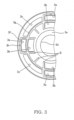
- FIG. 3 is a plan view of the piston 3 when viewed from the contraction-side chamber 60 side.
- the piston 3 is an annular member having a through-hole 3d, through which the small-diameter part 4a of the piston rod 4 penetrates, formed in the center thereof.
- the first communication passage 3a and the third communication passage 3c are provided alternately in the circumferential direction at portions toward the outer periphery of the piston 3.
- the second communication passage 3b is provided on the inside in the radial direction of the first communication passage 3a.
- a flat-shaped abutting part 3e which is abutted by the inner peripheral edge of the first leaf valve 41 is provided between the through-hole 3d and the second communication passage 3b. Further, a first seat part 3f and a second seat part 3g which are abutted by the first leaf valve 41 are provided respectively around the periphery of the opening edge of the first communication passage 3a and around the periphery of the opening edge of the second communication passage 3b.
- the first seat part 3f is formed so as to surround the opening edge of the first communication passage 3a, and the portion between the opening edge of the first communication passage 3a and the opening edge of the second communication passage 3b forms a common seat part with the second seat part 3g.
- a notch 3h is provided to the first seat part 3f that is provided on the outside in the radial direction of the first communication passage 3a.
- the notch 3h functions as an orifice, and allows communication between the extension-side chamber 50 and the contraction-side chamber 60 via the first communication passage 3a even when the first leaf valve 41 is abutting the first seat part 3f.
- the second seat part 3g is provided on the outside in the radial direction of the second communication passage 3b and is formed in an annular shape centered on the axial center of the piston 3. All of the second communication passages 3b are closed when the first leaf valve 41, the inner peripheral edge of which abuts the abutting part 3e, abuts the second seat part 3g.
- Support parts 3i which support the first leaf valve 41 are provided to the piston 3 between the second seat part 3g and the abutting part 3e.
- the support parts 3i are constituted by a plurality of ribs that extend radially inward from the second seat part 3g.
- the surface at which the support parts 3i contact the first leaf valve 41 is provided to be on the same plane as the surface at which the first seat part 3f, the second seat part 3g and the abutting part 3e contact the first leaf valve 41.
- the valve-opening pressure of an annular leaf valve is generally determined by the rigidity thereof, and decreases toward the free end.
- the initial load F is applied to the first leaf valve 41 at a position separated from the axial center O of the piston rod 4 by a predetermined distance (radius R). Therefore, the valve-opening pressure of the first leaf valve 41 increases more toward the inside in the radial direction from the position at which the initial load F is applied according to the magnitude of the initial load F.
- the valve-opening pressure of the first leaf valve 41 can be made to differ on the inside in the radial direction from the position at which the initial load F is applied and on the outside in the radial direction from the position at which the initial load F is applied.
- the valve-opening pressure of the entire first leaf valve 41 increases according to the magnitude of the initial load F. Therefore, the valve-opening pressure of the first leaf valve 41 cannot be made to differ on the inside in the radial direction and on the outside in the radial direction from the position at which the initial load F is applied. Further, if the position at which the initial load F is applied is on the abutting part 3e, the valve-opening pressure of the first leaf valve 41 does not change.
- the position at which the initial load F is applied is set within a range between the inside in the radial direction from the first seat part 3f, which is positioned on the outside in the radial direction of the first communication passage 3a, and the outside in the radial direction from the abutting part 3e.
- the valve-opening pressure of the first leaf valve 41 can be made to differ on the inside in the radial direction and on the outside in the radial direction from the position at which the initial load F is applied.
- FIG. 4 is a graph illustrating changes in the damping force characteristics when the position (radius R) at which the initial load F is applied is changed
- FIG. 5 is a graph illustrating changes in the damping force characteristics when the magnitude of the initial load F is changed.
- the damping valve 40 changes the damping force of the shock absorber 100 by changing the opening degree of the first communication passage 3a and the second communication passage 3b according to the movement speed of the piston 3 during extension of the shock absorber 100 in which the piston rod 4 moves out of the inner tube 1.
- the pressing force of the hydraulic oil that acts on the first leaf valve 41 is low, and thus the first leaf valve 41 is maintained in a state in which it is seated on the first seat part 3f and the second seat part 3g. Therefore, the hydraulic oil flows from the extension-side chamber 50 to the contraction-side chamber 60 via the notch 3h.
- the notch 3h functions as an orifice, and thus the damping force during this period exhibits square-law characteristics in which the damping force changes proportional to the square of the piston speed.
- the hydraulic oil flows from the extension-side chamber 50 to the contraction-side chamber 60 via a gap between the outer peripheral edge of the first leaf valve 41 and the first seat part 3f. This gap increases as the pressure of the hydraulic oil increases, i.e. as the piston speed increases.
- the damping force of the shock absorber 100 changes approximately proportional to the piston speed.
- the first leaf valve 41 separates from the second seat part 3g. Therefore, the hydraulic oil flows from the extension-side chamber 50 to the contraction-side chamber 60 via the first communication passage 3a, which has already been opened, as well as a gap between the first leaf valve 41 and the second seat part 3g. In this way, since the surface area of the passages that allow communication between the extension-side chamber 50 and the contraction-side chamber 60 increases together with an increase in the piston speed, the damping force of the shock absorber 100 increases gradually.
- the first communication passage 3a and the second communication passage 3b that are closed by the first leaf valve 41 are formed independently of each other, and thus the damping force after the first leaf valve 41 is opened changes in two stages as indicated by the solid line in FIG. 4 . Therefore, sudden changes in the damping force relative to the piston speed can be suppressed, and the riding comfort of the vehicle can be improved.
- the position at which the initial load F is applied i.e. the position which serves as a fulcrum of the deflection of the outer peripheral edge of the first leaf valve 41, is more toward the outside in the radial direction compared to the First Embodiment A1.
- the range in which the outer peripheral edge of the first leaf valve 41 can deflect in the axial direction is smaller compared to the First Embodiment A1, and the gap between the outer peripheral edge of the first leaf valve 41 and the first seat part 3f is smaller than that in the First Embodiment A1. Accordingly, as indicated by the dashed line in FIG. 4 , the damping force of the Second Embodiment A2 becomes larger than the damping force of the First Embodiment A1.
- the first leaf valve 41 opens the first communication passage 3a and also separates from the second seat part 3g. Therefore, the hydraulic oil flows from the extension-side chamber 50 to the contraction-side chamber 60 via the first communication passage 3a as well as a gap between the first leaf valve 41 and the second seat part 3g. As a result, the damping force of the Second Embodiment A2 increases gradually approximately proportional to the piston speed as in the First Embodiment A1.
- the position at which the initial load F is applied i.e. the position which serves as a fulcrum of the deflection of the outer peripheral edge of the first leaf valve 41, is more toward the inside in the radial direction compared to the First Embodiment A1. Therefore, if the pressure of the hydraulic oil, i.e. the piston speed, increases, the first leaf valve 41 separates from the first seat part 3f and also separates from the second seat part 3g.
- the gap through which the hydraulic oil can flow is larger than that in the First Embodiment A1. Accordingly, as indicated by the dash-dot line in FIG. 4 , the damping force of the Third Embodiment A3 becomes smaller than the damping force of the First Embodiment A1.
- the first leaf valve 41 further opens the second communication passage 3b. Therefore, the hydraulic oil flows from the extension-side chamber 50 to the contraction-side chamber 60 via the first communication passage 3a as well as the second communication passage 3b which has been opened. As a result, the damping force of the Third Embodiment A3 increases gradually approximately proportional to the piston speed as in the First Embodiment A1.
- the first leaf valve 41 is deformed to the piston 3 side by the initial load F between the second seat part 3g and the abutting part 3e, and thus the outer peripheral edge of the first leaf valve 41 may float up from the first seat part 3f.
- the support parts 3i are provided to the piston 3 between the second seat part 3g and the abutting part 3e.
- the first leaf valve 41 is supported by the support parts 3i, and thus even if the initial load F is applied, the first leaf valve 41 is prevented from deforming to the piston 3 side.
- the outer peripheral edge of the first leaf valve 41 is prevented from floating up from the first seat part 3f and the range in which the initial load F can be applied is broadened, and thus the desired damping force characteristics can be obtained.
- the damping force characteristics can be changed particularly in an intermediate speed region on the low-speed side as shown in FIG. 4 .
- the damping force increases as the radius R is increased, and the damping force decreases as the radius R is decreased.
- the damping force of the Fourth Embodiment A4 increases approximately proportional to the piston speed similar to the First Embodiment A1.
- the first leaf valve 41 opens the second communication passage 3b.
- the valve-opening pressure of the first leaf valve 41 on the inside in the radial direction from the position at which the initial load F is applied is larger than that of the First Embodiment A1. Therefore, as indicated by the dashed line in FIG. 5 , the damping force of the Fourth Embodiment A4 surpasses the damping force of the First Embodiment A1 in the region in which the piston speed is high.
- the position at which the initial load F is applied i.e. the position which serves as a fulcrum of the deflection of the outer peripheral edge of the first leaf valve 41, is the same as in the First Embodiment A1.. Therefore, the damping force of the Fifth Embodiment A5 increases approximately proportional to the piston speed similar to the First Embodiment A1.
- the first leaf valve 41 opens the second communication passage 3b.
- the valve-opening pressure of the first leaf valve 41 on the inside in the radial direction from the position at which the initial load F is applied is smaller than that of the First Embodiment A1. Therefore, as indicated by the dash-dot line in FIG. 5 , the damping force of the Fifth Embodiment A5 falls below the damping force of the First Embodiment A1 in the region in which the piston speed is high.
- the damping force characteristics can be changed particularly in the high-speed region as shown in FIG. 5 .
- the damping force increases as the magnitude of the initial load F is increased, and the damping force decreases as the magnitude of the initial load F is decreased.
- the damping force characteristics can be changed in a broad range of piston speeds by changing the radius R at which the initial load F acts and by changing the magnitude of the initial load F.
- the first communication passage 3a and the second communication passage 3b which are closed by the first leaf valve 41, are formed individually, and thus as shown in FIGS. 4 and 5 , the damping force changes gradually according to the piston speed without any sudden changes. As a result, damping force characteristics which improve the riding comfort of the vehicle can be realized.
- the valve structure of the shock absorber 100 includes the following: the piston 3 that is provided within the inner tube 1 and partitions the contraction-side chamber 60 and the extension-side chamber 50; the first communication passage 3a that is provided to the piston 3 and allows communication between the contraction-side chamber 60 and the extension-side chamber 50; the second communication passage 3b that is provided to the piston 3 more toward the inside in the radial direction than the first communication passage 3a, and allows communication between the contraction-side chamber 60 and the extension-side chamber 50; the first seat part 3f that is provided around the periphery of the opening edge of the first communication passage 3a on the contraction-side chamber 60 side; the second seat part 3g that is provided around the periphery of the opening edge of the second communication passage 3b on the contraction-side chamber 60 side; the annular first leaf valve 41 that abuts the first seat part 3f and the second seat part 3g; and the load application member 42 that applies the initial load F which pushes the first leaf valve 41 to the first seat part 3f and the second seat part 3g.
- the piston 3 includes the abutting part 3e which is abutted by the inner peripheral edge of the first leaf valve 41, and the initial load F is applied to the first leaf valve 41 within a range between the inside in the radial direction from the first seat part 3f, which is positioned on the outside in the radial direction of the first communication passage 3a, and the outside in the radial direction from the abutting part 3e.
- the load which causes the first leaf valve 41 to separate from the first seat part 3f and the second seat part 3g is changed by changing the position at which the initial load F is applied and by changing the magnitude of the initial load F.
- the damping force characteristics of the shock absorber 100 can be modified over a wide range of piston speeds.
- the damping force characteristics in the low to intermediate speed region can be modified, and by changing the magnitude of the initial load F, the damping force characteristics on the high-speed side can be modified.
- the passages which are closed by the first leaf valve 41 are formed individually, and thus the damping force changes gradually from the low-speed side to the high-speed side.
- the damping force in the intermediate speed region can be adjusted so that the damping force on the low-speed side and the damping force on the high-speed side are smoothly connected.
- sudden changes in the damping force relative to the piston speed can be suppressed, and the riding comfort of the vehicle can be improved.
- the passages which are closed by the first leaf valve 41 are formed individually, and the piston speed at which each passage opens upon application of the initial load F to the first leaf valve 41 is different. Therefore, by opening the first communication passage 3a on the outer peripheral edge side of the first leaf valve 41 earlier, the region of the damping force characteristics which serve as the valve characteristics can be expanded to the low-speed side. As a result, the region of the orifice characteristics becomes smaller, and thus the damping coefficient of the orifice characteristics can be increased and the damping force in the extremely low speed region can be increased.
- the piston 3 further includes the support parts 3i which are provided between the second seat part 3g and the abutting part 3e and support the first leaf valve 41.
- the first leaf valve 41 deforms to the piston 3 side, and the outer peripheral edge of the first leaf valve 41 may float up from the first seat part 3f.
- the support parts 3i are provided to the piston 3 between the second seat part 3g and the abutting part 3e.
- the first leaf valve 41 is supported by the support parts 3i, and thus even if the initial load F is applied, the first leaf valve 41 is prevented from deforming to the piston 3 side.
- the outer peripheral edge of the first leaf valve 41 is prevented from floating up from the first seat part 3f, and thus the desired damping force characteristics can be obtained.
- the initial load F is applied to the first leaf valve 41 within a range between the inside in the radial direction from the first seat part 3f, which is positioned on the outside in the radial direction of the first communication passage 3a, and the outside in the radial direction from the support parts 3i.
- the first leaf valve 41 is supported by the support parts 3i so that the first leaf valve 41 is prevented from deforming to the piston 3 side, and the damping force characteristics can be arbitrarily modified from the low-speed region to the high-speed region by changing the position at which the initial load F is applied to the first leaf valve 41.
- the load application member 42 includes the following: the annular second leaf valve 43; and the annular transmission plate 44 that is sandwiched between the first leaf valve 41 and the second leaf valve 43.
- the transmission plate 44 has the protrusion 44a that protrudes in the axial direction and abuts the first leaf valve 41 or the second leaf valve 43.
- the initial load F is applied to the first leaf valve 41 from the second leaf valve 43 via the transmission plate 44. Therefore, the position at which the initial load F is applied to the first leaf valve 41 and the magnitude of the initial load F can be easily changed by modifying the outer diameter of the transmission plate 44, the protrusion amount of the protrusion 44a, the rigidity of the second leaf valve 43, and the like. As a result, the desired damping force characteristics can be easily realized.
- hydraulic oil is used as the working fluid, but another liquid such as water or the like may be used.
- the load application member 42 is not limited to using the repulsive force of the second leaf valve 43, and may use the elastic force of a coil spring, etc. supported at one end by the nut 11, etc.
- the valve structure is not limited to being constituted by the piston 3 and the damping valve 40 of the twin-tube type shock absorber, and the valve structure may be constituted by the base valve 8 and the damping valve 10 of the twin-tube type shock absorber. Further, the valve structure may be used in a mono-tube type shock absorber to apply resistance to hydraulic oil flowing from the contraction-side chamber to the extension-side chamber or to apply resistance to hydraulic oil flowing from the extension-side chamber to the contraction-side chamber.
- the surface at which the first seat part 3f, the second seat part 3g, the support parts 3i, and the abutting part 3e provided to the piston 3 contact the first leaf valve 41 may be formed so as to be inclined to become higher toward the outer peripheral edge of the first leaf valve 41. In this case, it becomes easier for the first leaf valve 41 to contact the seat parts, and the sealing performance can be improved.
- the passages that are opened/closed by the first leaf valve 41 are not limited to the first communication passage 3a and the second communication passage 3b, and three or more passages can be formed aligned in the radial direction.
- an independent passage may be further provided on the inside in the radial direction from the second communication passage 3b.
- the rigidity of the first leaf valve 41, the second leaf valve 43, and the transmission plate 44 may be appropriately modified.
Landscapes
- Engineering & Computer Science (AREA)
- General Engineering & Computer Science (AREA)
- Mechanical Engineering (AREA)
- Physics & Mathematics (AREA)
- Fluid Mechanics (AREA)
- Fluid-Damping Devices (AREA)
Applications Claiming Priority (2)
| Application Number | Priority Date | Filing Date | Title |
|---|---|---|---|
| JP2015157518A JP6487804B2 (ja) | 2015-08-07 | 2015-08-07 | 緩衝器のバルブ構造 |
| PCT/JP2016/072699 WO2017026332A1 (ja) | 2015-08-07 | 2016-08-02 | 緩衝器のバルブ構造 |
Publications (3)
| Publication Number | Publication Date |
|---|---|
| EP3333446A1 EP3333446A1 (en) | 2018-06-13 |
| EP3333446A4 EP3333446A4 (en) | 2019-04-17 |
| EP3333446B1 true EP3333446B1 (en) | 2024-06-12 |
Family
ID=57983152
Family Applications (1)
| Application Number | Title | Priority Date | Filing Date |
|---|---|---|---|
| EP16835029.6A Active EP3333446B1 (en) | 2015-08-07 | 2016-08-02 | Valve structure for buffer |
Country Status (5)
| Country | Link |
|---|---|
| US (1) | US10837514B2 (ja) |
| EP (1) | EP3333446B1 (ja) |
| JP (1) | JP6487804B2 (ja) |
| CN (1) | CN107923469B (ja) |
| WO (1) | WO2017026332A1 (ja) |
Families Citing this family (3)
| Publication number | Priority date | Publication date | Assignee | Title |
|---|---|---|---|---|
| DE102017207605A1 (de) * | 2017-05-05 | 2018-11-08 | Zf Friedrichshafen Ag | Dämpfventil für einen Schwingungsdämpfer |
| JP6949123B2 (ja) * | 2017-08-29 | 2021-10-13 | 日立Astemo株式会社 | 緩衝器 |
| WO2019239521A1 (ja) | 2018-06-13 | 2019-12-19 | 株式会社ショーワ | 圧力緩衝装置 |
Citations (2)
| Publication number | Priority date | Publication date | Assignee | Title |
|---|---|---|---|---|
| US4905799A (en) * | 1988-04-04 | 1990-03-06 | Atsugi Motor Parts Company, Limited | Shock absorber |
| JP2000337422A (ja) * | 1999-05-26 | 2000-12-05 | Kayaba Ind Co Ltd | 油圧緩衝器のバルブ構造 |
Family Cites Families (18)
| Publication number | Priority date | Publication date | Assignee | Title |
|---|---|---|---|---|
| DE2600820C3 (de) * | 1976-01-12 | 1982-02-04 | Volkswagenwerk Ag, 3180 Wolfsburg | Tellerfederventil für Stoßdämpfer |
| JPS5812746U (ja) * | 1981-07-20 | 1983-01-26 | トキコ株式会社 | 油圧緩衝器の減衰力発生機構 |
| JPH01135935A (ja) * | 1987-11-18 | 1989-05-29 | Nhk Spring Co Ltd | 減衰力発生装置 |
| JPH06185562A (ja) * | 1992-12-18 | 1994-07-05 | Tokico Ltd | 油圧緩衝器 |
| JP2557830Y2 (ja) * | 1993-11-19 | 1997-12-17 | 株式会社貝印刃物開発センター | 容器陳列用引掛具 |
| JP3414090B2 (ja) * | 1995-11-20 | 2003-06-09 | トヨタ自動車株式会社 | 液圧緩衝器のバルブ構造 |
| JP3303021B2 (ja) * | 1996-05-15 | 2002-07-15 | ヤマハ発動機株式会社 | 油圧緩衝器 |
| GB2337097A (en) * | 1998-05-07 | 1999-11-10 | Delphi France Automotive Sys | Hydraulic shock absorber |
| GB2437185B (en) | 2003-09-29 | 2008-05-14 | Tenneco Automotive Operating | Extra support land for valve disc |
| JP4726039B2 (ja) * | 2005-01-13 | 2011-07-20 | カヤバ工業株式会社 | バルブ構造 |
| JP5115814B2 (ja) * | 2008-05-30 | 2013-01-09 | 日立オートモティブシステムズ株式会社 | 緩衝器 |
| US8297418B2 (en) | 2008-06-05 | 2012-10-30 | Tenneco Automotive Operating Company Inc. | Nested check high speed valve |
| JP2011179550A (ja) * | 2010-02-26 | 2011-09-15 | Hitachi Automotive Systems Ltd | 緩衝器 |
| JP5833957B2 (ja) * | 2012-03-14 | 2015-12-16 | Kyb株式会社 | 緩衝器のバルブ構造 |
| JP6014444B2 (ja) * | 2012-09-28 | 2016-10-25 | 日立オートモティブシステムズ株式会社 | 緩衝器 |
| JP5588497B2 (ja) * | 2012-11-16 | 2014-09-10 | カヤバ工業株式会社 | ピストンおよび緩衝器 |
| JP6071646B2 (ja) * | 2012-11-30 | 2017-02-01 | 日立オートモティブシステムズ株式会社 | 緩衝器 |
| JP6360291B2 (ja) | 2013-11-06 | 2018-07-18 | Kyb株式会社 | 緩衝器のバルブ構造 |
-
2015
- 2015-08-07 JP JP2015157518A patent/JP6487804B2/ja active Active
-
2016
- 2016-08-02 US US15/750,659 patent/US10837514B2/en active Active
- 2016-08-02 WO PCT/JP2016/072699 patent/WO2017026332A1/ja active Application Filing
- 2016-08-02 EP EP16835029.6A patent/EP3333446B1/en active Active
- 2016-08-02 CN CN201680046619.3A patent/CN107923469B/zh active Active
Patent Citations (2)
| Publication number | Priority date | Publication date | Assignee | Title |
|---|---|---|---|---|
| US4905799A (en) * | 1988-04-04 | 1990-03-06 | Atsugi Motor Parts Company, Limited | Shock absorber |
| JP2000337422A (ja) * | 1999-05-26 | 2000-12-05 | Kayaba Ind Co Ltd | 油圧緩衝器のバルブ構造 |
Also Published As
| Publication number | Publication date |
|---|---|
| JP2017036775A (ja) | 2017-02-16 |
| US10837514B2 (en) | 2020-11-17 |
| US20200088261A1 (en) | 2020-03-19 |
| CN107923469B (zh) | 2019-11-08 |
| EP3333446A4 (en) | 2019-04-17 |
| EP3333446A1 (en) | 2018-06-13 |
| JP6487804B2 (ja) | 2019-03-20 |
| WO2017026332A1 (ja) | 2017-02-16 |
| CN107923469A (zh) | 2018-04-17 |
Similar Documents
| Publication | Publication Date | Title |
|---|---|---|
| JP5758119B2 (ja) | 緩衝器 | |
| KR102588959B1 (ko) | 완충기 | |
| JP5684925B2 (ja) | 緩衝器 | |
| JP5115814B2 (ja) | 緩衝器 | |
| JP7224383B2 (ja) | 緩衝器 | |
| US11536344B2 (en) | Valve and shock absorber | |
| JP6078635B2 (ja) | 緩衝器およびこれを用いた車両 | |
| JP5909557B2 (ja) | サスペンション装置 | |
| KR20110098630A (ko) | 완충기 | |
| JP2013050198A (ja) | 緩衝器 | |
| WO2018062150A1 (ja) | 緩衝器 | |
| JP6663920B2 (ja) | 緩衝器 | |
| JP2016050613A (ja) | 緩衝器 | |
| JP2012031900A (ja) | 緩衝器 | |
| JP2016050612A (ja) | 緩衝器 | |
| EP3333446B1 (en) | Valve structure for buffer | |
| CN109073024B (zh) | 用于减震器的频率依赖活塞组件和减震器 | |
| JP2007120726A (ja) | 油圧緩衝器 | |
| JP5798813B2 (ja) | 緩衝器 | |
| JP5894874B2 (ja) | 緩衝器 | |
| JP2017190806A (ja) | ショックアブソーバ | |
| JP7541197B2 (ja) | 緩衝器 | |
| WO2023106329A1 (ja) | 緩衝器 | |
| JP2013204779A (ja) | 緩衝器 | |
| JP2019183920A (ja) | バルブ及び緩衝器 |
Legal Events
| Date | Code | Title | Description |
|---|---|---|---|
| STAA | Information on the status of an ep patent application or granted ep patent |
Free format text: STATUS: THE INTERNATIONAL PUBLICATION HAS BEEN MADE |
|
| PUAI | Public reference made under article 153(3) epc to a published international application that has entered the european phase |
Free format text: ORIGINAL CODE: 0009012 |
|
| STAA | Information on the status of an ep patent application or granted ep patent |
Free format text: STATUS: REQUEST FOR EXAMINATION WAS MADE |
|
| 17P | Request for examination filed |
Effective date: 20180227 |
|
| AK | Designated contracting states |
Kind code of ref document: A1 Designated state(s): AL AT BE BG CH CY CZ DE DK EE ES FI FR GB GR HR HU IE IS IT LI LT LU LV MC MK MT NL NO PL PT RO RS SE SI SK SM TR |
|
| AX | Request for extension of the european patent |
Extension state: BA ME |
|
| DAV | Request for validation of the european patent (deleted) | ||
| DAX | Request for extension of the european patent (deleted) | ||
| RIC1 | Information provided on ipc code assigned before grant |
Ipc: F16F 9/348 20060101AFI20190307BHEP Ipc: F16F 9/512 20060101ALI20190307BHEP |
|
| A4 | Supplementary search report drawn up and despatched |
Effective date: 20190315 |
|
| STAA | Information on the status of an ep patent application or granted ep patent |
Free format text: STATUS: EXAMINATION IS IN PROGRESS |
|
| 17Q | First examination report despatched |
Effective date: 20221108 |
|
| RIC1 | Information provided on ipc code assigned before grant |
Ipc: F16F 9/512 20060101ALN20240124BHEP Ipc: F16F 9/348 20060101AFI20240124BHEP |
|
| GRAP | Despatch of communication of intention to grant a patent |
Free format text: ORIGINAL CODE: EPIDOSNIGR1 |
|
| STAA | Information on the status of an ep patent application or granted ep patent |
Free format text: STATUS: GRANT OF PATENT IS INTENDED |
|
| INTG | Intention to grant announced |
Effective date: 20240318 |
|
| GRAS | Grant fee paid |
Free format text: ORIGINAL CODE: EPIDOSNIGR3 |
|
| GRAA | (expected) grant |
Free format text: ORIGINAL CODE: 0009210 |
|
| STAA | Information on the status of an ep patent application or granted ep patent |
Free format text: STATUS: THE PATENT HAS BEEN GRANTED |
|
| AK | Designated contracting states |
Kind code of ref document: B1 Designated state(s): AL AT BE BG CH CY CZ DE DK EE ES FI FR GB GR HR HU IE IS IT LI LT LU LV MC MK MT NL NO PL PT RO RS SE SI SK SM TR |
|
| REG | Reference to a national code |
Ref country code: GB Ref legal event code: FG4D |
|
| REG | Reference to a national code |
Ref country code: CH Ref legal event code: EP |
|
| REG | Reference to a national code |
Ref country code: DE Ref legal event code: R096 Ref document number: 602016087978 Country of ref document: DE |
|
| REG | Reference to a national code |
Ref country code: IE Ref legal event code: FG4D |