EP3333252B1 - Biologische festkörperreaktionsvorrichtung, verwendungsverfahren und verwendung davon - Google Patents
Biologische festkörperreaktionsvorrichtung, verwendungsverfahren und verwendung davon Download PDFInfo
- Publication number
- EP3333252B1 EP3333252B1 EP16832341.8A EP16832341A EP3333252B1 EP 3333252 B1 EP3333252 B1 EP 3333252B1 EP 16832341 A EP16832341 A EP 16832341A EP 3333252 B1 EP3333252 B1 EP 3333252B1
- Authority
- EP
- European Patent Office
- Prior art keywords
- main tank
- disposed
- solid state
- culture
- biological reaction
- Prior art date
- Legal status (The legal status is an assumption and is not a legal conclusion. Google has not performed a legal analysis and makes no representation as to the accuracy of the status listed.)
- Not-in-force
Links
Images





Classifications
-
- C—CHEMISTRY; METALLURGY
- C12—BIOCHEMISTRY; BEER; SPIRITS; WINE; VINEGAR; MICROBIOLOGY; ENZYMOLOGY; MUTATION OR GENETIC ENGINEERING
- C12M—APPARATUS FOR ENZYMOLOGY OR MICROBIOLOGY; APPARATUS FOR CULTURING MICROORGANISMS FOR PRODUCING BIOMASS, FOR GROWING CELLS OR FOR OBTAINING FERMENTATION OR METABOLIC PRODUCTS, i.e. BIOREACTORS OR FERMENTERS
- C12M21/00—Bioreactors or fermenters specially adapted for specific uses
- C12M21/16—Solid state fermenters, e.g. for koji production
-
- C—CHEMISTRY; METALLURGY
- C12—BIOCHEMISTRY; BEER; SPIRITS; WINE; VINEGAR; MICROBIOLOGY; ENZYMOLOGY; MUTATION OR GENETIC ENGINEERING
- C12M—APPARATUS FOR ENZYMOLOGY OR MICROBIOLOGY; APPARATUS FOR CULTURING MICROORGANISMS FOR PRODUCING BIOMASS, FOR GROWING CELLS OR FOR OBTAINING FERMENTATION OR METABOLIC PRODUCTS, i.e. BIOREACTORS OR FERMENTERS
- C12M1/00—Apparatus for enzymology or microbiology
- C12M1/04—Apparatus for enzymology or microbiology with gas introduction means
-
- C—CHEMISTRY; METALLURGY
- C12—BIOCHEMISTRY; BEER; SPIRITS; WINE; VINEGAR; MICROBIOLOGY; ENZYMOLOGY; MUTATION OR GENETIC ENGINEERING
- C12M—APPARATUS FOR ENZYMOLOGY OR MICROBIOLOGY; APPARATUS FOR CULTURING MICROORGANISMS FOR PRODUCING BIOMASS, FOR GROWING CELLS OR FOR OBTAINING FERMENTATION OR METABOLIC PRODUCTS, i.e. BIOREACTORS OR FERMENTERS
- C12M1/00—Apparatus for enzymology or microbiology
- C12M1/16—Apparatus for enzymology or microbiology containing, or adapted to contain, solid media
-
- C—CHEMISTRY; METALLURGY
- C12—BIOCHEMISTRY; BEER; SPIRITS; WINE; VINEGAR; MICROBIOLOGY; ENZYMOLOGY; MUTATION OR GENETIC ENGINEERING
- C12M—APPARATUS FOR ENZYMOLOGY OR MICROBIOLOGY; APPARATUS FOR CULTURING MICROORGANISMS FOR PRODUCING BIOMASS, FOR GROWING CELLS OR FOR OBTAINING FERMENTATION OR METABOLIC PRODUCTS, i.e. BIOREACTORS OR FERMENTERS
- C12M23/00—Constructional details, e.g. recesses, hinges
- C12M23/48—Holding appliances; Racks; Supports
-
- C—CHEMISTRY; METALLURGY
- C12—BIOCHEMISTRY; BEER; SPIRITS; WINE; VINEGAR; MICROBIOLOGY; ENZYMOLOGY; MUTATION OR GENETIC ENGINEERING
- C12M—APPARATUS FOR ENZYMOLOGY OR MICROBIOLOGY; APPARATUS FOR CULTURING MICROORGANISMS FOR PRODUCING BIOMASS, FOR GROWING CELLS OR FOR OBTAINING FERMENTATION OR METABOLIC PRODUCTS, i.e. BIOREACTORS OR FERMENTERS
- C12M23/00—Constructional details, e.g. recesses, hinges
- C12M23/50—Means for positioning or orientating the apparatus
-
- C—CHEMISTRY; METALLURGY
- C12—BIOCHEMISTRY; BEER; SPIRITS; WINE; VINEGAR; MICROBIOLOGY; ENZYMOLOGY; MUTATION OR GENETIC ENGINEERING
- C12M—APPARATUS FOR ENZYMOLOGY OR MICROBIOLOGY; APPARATUS FOR CULTURING MICROORGANISMS FOR PRODUCING BIOMASS, FOR GROWING CELLS OR FOR OBTAINING FERMENTATION OR METABOLIC PRODUCTS, i.e. BIOREACTORS OR FERMENTERS
- C12M25/00—Means for supporting, enclosing or fixing the microorganisms, e.g. immunocoatings
- C12M25/06—Plates; Walls; Drawers; Multilayer plates
-
- C—CHEMISTRY; METALLURGY
- C12—BIOCHEMISTRY; BEER; SPIRITS; WINE; VINEGAR; MICROBIOLOGY; ENZYMOLOGY; MUTATION OR GENETIC ENGINEERING
- C12M—APPARATUS FOR ENZYMOLOGY OR MICROBIOLOGY; APPARATUS FOR CULTURING MICROORGANISMS FOR PRODUCING BIOMASS, FOR GROWING CELLS OR FOR OBTAINING FERMENTATION OR METABOLIC PRODUCTS, i.e. BIOREACTORS OR FERMENTERS
- C12M27/00—Means for mixing, agitating or circulating fluids in the vessel
- C12M27/10—Rotating vessel
-
- C—CHEMISTRY; METALLURGY
- C12—BIOCHEMISTRY; BEER; SPIRITS; WINE; VINEGAR; MICROBIOLOGY; ENZYMOLOGY; MUTATION OR GENETIC ENGINEERING
- C12M—APPARATUS FOR ENZYMOLOGY OR MICROBIOLOGY; APPARATUS FOR CULTURING MICROORGANISMS FOR PRODUCING BIOMASS, FOR GROWING CELLS OR FOR OBTAINING FERMENTATION OR METABOLIC PRODUCTS, i.e. BIOREACTORS OR FERMENTERS
- C12M29/00—Means for introduction, extraction or recirculation of materials, e.g. pumps
- C12M29/04—Filters; Permeable or porous membranes or plates, e.g. dialysis
-
- C—CHEMISTRY; METALLURGY
- C12—BIOCHEMISTRY; BEER; SPIRITS; WINE; VINEGAR; MICROBIOLOGY; ENZYMOLOGY; MUTATION OR GENETIC ENGINEERING
- C12M—APPARATUS FOR ENZYMOLOGY OR MICROBIOLOGY; APPARATUS FOR CULTURING MICROORGANISMS FOR PRODUCING BIOMASS, FOR GROWING CELLS OR FOR OBTAINING FERMENTATION OR METABOLIC PRODUCTS, i.e. BIOREACTORS OR FERMENTERS
- C12M41/00—Means for regulation, monitoring, measurement or control, e.g. flow regulation
- C12M41/12—Means for regulation, monitoring, measurement or control, e.g. flow regulation of temperature
-
- C—CHEMISTRY; METALLURGY
- C12—BIOCHEMISTRY; BEER; SPIRITS; WINE; VINEGAR; MICROBIOLOGY; ENZYMOLOGY; MUTATION OR GENETIC ENGINEERING
- C12M—APPARATUS FOR ENZYMOLOGY OR MICROBIOLOGY; APPARATUS FOR CULTURING MICROORGANISMS FOR PRODUCING BIOMASS, FOR GROWING CELLS OR FOR OBTAINING FERMENTATION OR METABOLIC PRODUCTS, i.e. BIOREACTORS OR FERMENTERS
- C12M41/00—Means for regulation, monitoring, measurement or control, e.g. flow regulation
- C12M41/12—Means for regulation, monitoring, measurement or control, e.g. flow regulation of temperature
- C12M41/18—Heat exchange systems, e.g. heat jackets or outer envelopes
- C12M41/22—Heat exchange systems, e.g. heat jackets or outer envelopes in contact with the bioreactor walls
-
- C—CHEMISTRY; METALLURGY
- C12—BIOCHEMISTRY; BEER; SPIRITS; WINE; VINEGAR; MICROBIOLOGY; ENZYMOLOGY; MUTATION OR GENETIC ENGINEERING
- C12N—MICROORGANISMS OR ENZYMES; COMPOSITIONS THEREOF; PROPAGATING, PRESERVING, OR MAINTAINING MICROORGANISMS; MUTATION OR GENETIC ENGINEERING; CULTURE MEDIA
- C12N1/00—Microorganisms; Compositions thereof; Processes of propagating, maintaining or preserving microorganisms or compositions thereof; Processes of preparing or isolating a composition containing a microorganism; Culture media therefor
-
- C—CHEMISTRY; METALLURGY
- C12—BIOCHEMISTRY; BEER; SPIRITS; WINE; VINEGAR; MICROBIOLOGY; ENZYMOLOGY; MUTATION OR GENETIC ENGINEERING
- C12N—MICROORGANISMS OR ENZYMES; COMPOSITIONS THEREOF; PROPAGATING, PRESERVING, OR MAINTAINING MICROORGANISMS; MUTATION OR GENETIC ENGINEERING; CULTURE MEDIA
- C12N1/00—Microorganisms; Compositions thereof; Processes of propagating, maintaining or preserving microorganisms or compositions thereof; Processes of preparing or isolating a composition containing a microorganism; Culture media therefor
- C12N1/14—Fungi; Culture media therefor
-
- C—CHEMISTRY; METALLURGY
- C12—BIOCHEMISTRY; BEER; SPIRITS; WINE; VINEGAR; MICROBIOLOGY; ENZYMOLOGY; MUTATION OR GENETIC ENGINEERING
- C12N—MICROORGANISMS OR ENZYMES; COMPOSITIONS THEREOF; PROPAGATING, PRESERVING, OR MAINTAINING MICROORGANISMS; MUTATION OR GENETIC ENGINEERING; CULTURE MEDIA
- C12N1/00—Microorganisms; Compositions thereof; Processes of propagating, maintaining or preserving microorganisms or compositions thereof; Processes of preparing or isolating a composition containing a microorganism; Culture media therefor
- C12N1/14—Fungi; Culture media therefor
- C12N1/16—Yeasts; Culture media therefor
- C12N1/18—Baker's yeast; Brewer's yeast
Definitions
- the present disclosure belongs to the field of bioengineering, specifically to a solid state biological reaction device, a usage method and use thereof.
- the filamentous organisms are producing strains of many fermentation products, and are widely used in industries such as antibiotic, organic acid, enzyme preparation and biopesticide industry. Spore inoculation is an inoculation method commonly used in the fermentation of filamentous organisms. In the fermentation production, the spore strains of the filamentous organisms are generally prepared by surface culture (such as solid-state culture).
- a method of standing and intermittently inversing Erlenmeyer flask is generally for solid-state culturing to prepare bran koji spores of Aspergillus niger in citric acid industry, its brief technological process comprises: charging fresh brans into a Erlenmeyer flask and sterilizing, then putting the flask on a shelf after inoculation for stationary culture, during the culture process, the flask is inversed intermittently, at the end of culturing, drying the culture and storing for use, the culture is then inoculated into a seeding tank or a fermenter in use.
- the device adopts a technical route of culturing in multilayer trays and collecting the pure spores by vacuum, and the culturing, drying and collecting of the spores are all performed in a closed system, with a production capacity of 0.8-1.4 kg of Aspergillus niger pure spores per batch and a cycle of 14 days.
- the sterilizing agent since the device uses chemical fumigation for sterilization, the sterilizing agent must be completely evacuated so as not to affect the growth of the microorganism, and the evacuated sterilizing agent is needed to be neutralized to prevent environmental pollution; the agar culture medium is sterilized separately and then aseptically transferred into a box-type culture device, which is at high risk of contamination during the transferring; the time for cleaning and preparing is long and the amount of manual labor is still large; the agar culture medium is higher in cost as well; furthermore, the collection of spores by using negative pressure will also bring a higher risk of contamination.
- CN 104630020 A discloses a solid state biological reaction device for the large scale production of the spore strains of the filamentous organisms, the dry spore powder produced by this device can be used for immediate inoculation to fermenter and for aseptic preservation in a spore collection flask for a long period of time.
- a small-size production device of the filamentous organism spores with more simple and compact structure, lower manufacturing costs and more flexibility of use.
- the mixing system of the device can be simplified in the design, the manufacturing costs of the device can be saved significantly.
- CN 203559041 U discloses a movable wine fermenter, which is suitable for use in wine fermentation, the movement function of which is a horizontal movement that can neither realize the rotation of the fermenter attitude nor have the function of rotary mixing, therefore it is not suitable for producing the filamentous organism spores by solid state biological reaction.
- CN 102924146A discloses a movable drum composting reactor which is designed for use as a solid state biological reactor, a rotary mixing of which is realized via rotating the drum, but the movement mode is limited to a horizontal movement, and the rotation mode is limited to a fixed axis rotation, which can neither realize a change in space attitude of the vessel nor be suitable for producing pure-culturing spore strains of the filamentous organisms by solid state biological reaction.
- CN103911282A discloses a fermentor tank that can operate at both horizontal and vertical position. The two positions, perpendicular to each other, hence the change of position is obtained by reassembling the structure of an angle of 90°.
- the present disclosure provides a solid state biological reaction device, a usage method and a use thereof, the objects of which are to realize a low strength mixing of the materials in a small-size solid state reactor by changing the space attitude and rotating the vessel, meanwhile satisfying different requirements of the culturing and the material mixing for the attitude of the device, and simplifying the design as well as saving costs.
- the present disclosure can not only be used for the large scale production of filamentous organism spores, but also for the general solid state culturing and solid state fermentation of a microorganism.
- At least one screen plate is disposed inside the main tank for holding the position of the materials.
- the opening ratio of the screen plate is from 1 to 90%, preferably from 1 to 60%.
- the outer edge of the screen plate is seal connected to the inner wall of the main tank, and the seal connecting may be a flexible seal or a rigid seal.
- the screen plate may not be a full-opening screen plate, and the annular non-opening region can maintain a part of the free liquid culture medium in the side wall during the high temperature sterilization, ensuring that the culture matrix particles can fully absorb the liquid culture medium and swell, thereby ensuring that the seed solution has sufficient contact with the culture matrix and is fully absorbed during the mixing process after inoculation.
- the ratio of the diameter of the opening area of the screen plate to the outer diameter of the screen plate is from 0.1 to 1, for example can be 0.1, 0.2, 0.3, 0.4, 0.5, 0.55, 0.6, 0.7, 0.8, 0.9 or 1, preferably from 0.5 to 0.9.
- the opening in the screen plate can be but are not limited to a circular hole and/or an obround hole slot, and can also be an elliptical hole, a triangular hole, a polygonal hole, or an irregular hole.
- the diameter of the circular hole is from 0.2 to 20 mm, for example can be 0.2 mm, 0.3 mm, 0.4 mm, 0.5mm, 0.6 mm, 0.8 mm, 1 mm, 2 mm, 3 mm, 4 mm, 5 mm, 6 mm, 8 mm, 10 mm, 12 mm, 15 mm, 16 mm, 18 mm, 19 mm or 20 mm, preferably from 0.5 to 3 mm.
- the width of the obround hole slot is from 0.2 to 20 mm, for example can be 0.2 mm, 0.3 mm, 0.4 mm, 0.5 mm, 0.6 mm, 0.8 mm, 1 mm, 2 mm, 3 mm, 4 mm, 5 mm, 6 mm, 8 mm, 10 mm, 12 mm, 15 mm, 16 mm, 18 mm, 19 mm or 20 mm, preferably from 0.5 to 3 mm.
- the opening ratio of the screen plate can be provided according to the requirements of the strains for the ventilation rate, and the opening ratio and the aperture can be adjusted as well.
- the main tank comprises an end cap, a cylinder and a lower head arranged from top to bottom;
- the sight glass has a circular shape or a stripe shape, preferably a stripe shape.
- a check valve is disposed between the air inlet filter and the lower head.
- a pipe joint is disposed at the upstream of the air inlet filter for connecting the compressed air pipeline.
- the pore diameter of the off-gas filter, the liquid filter and the air inlet filter is from 0.1 to 0.22 ⁇ m, for example can be 0.1 ⁇ m, 0.15 ⁇ m, 0.2 ⁇ m, 0.21 ⁇ m or 0.22 ⁇ m, preferably 0.2 ⁇ m.
- the main tank comprises an upper screen plate disposed at the internal junction of the end cap and the cylinder, and a lower screen plate disposed at the internal junction of the cylinder and the lower head.
- the device may be provided with a set of screen plates comprising an upper screen plate and a lower screen plate, or may also be provided with multiple sets of screen plates having different diameters in the opening area, holes with different shapes and different geometrical dimensions, and different opening rate to suit different strains and materials.
- an upper spacing ring is disposed along the top edge of the cylinder, and a lower spacing ring is disposed along the top edge of the lower head.
- a jacket is disposed at the exterior of the cylinder, preferably a jacket is disposed at the exterior of the cylinder and the lower head, the jacket comprises a water inlet pipe disposed at the lower portion of the jacket and a water outlet pipe disposed at the upper portion of the jacket.
- the jacket can cover all of the exposable portions of the cylinder and the lower head without any component disposed thereon, or can cover only the cylinder portion, or can cover only the lower head.
- an off-gas regulating valve is disposed between the end cap and the off-gas filter
- an isolation valve is disposed between the end cap and the liquid filter.
- the support can change the attitude of the main tank and can be a carrier vehicle, preferably a lever-type trailer;
- a rotary driving device is disposed at the inner side of the pillar for driving the main tank to rotate.
- the rotary driving device can be in electrically driving or pneumatically driving manner, and the rotational speed can be adjusted.
- the horizontal supporting leg and the vertical supporting leg can also be a caster wheel provided with a locking means.
- the horizontal supporting leg and the vertical supporting leg can be adjusted by a thread, and the stability of the main tank can be ensured when it is in a vertical position or a horizontal position.
- the main tank is connected to the lever-type trailer, such that the main tank can not only change the horizontal and the vertical positions along with the lever-type trailer to facilitate the mixing of the materials and the suspension of strains; meanwhile, the main tank can be easily moved to a desired place for seed culture transferring by the lever-type trailer without additional operating steps, thereby reducing the likelihood of contamination.
- the upper surface of the annular supporting seat is provided with a sliding bearing.
- the supporting wheel is disposed at the inner side of the pillar as a side wall support for the main tank during horizontal placement and horizontal rotation.
- the supporting wheel when the device is put down to a horizontal position, the supporting wheel is used to bear the weight of the main tank while ensuring that the main tank can freely rotate, and the height of the supporting wheel can be adjusted by means of the bolts on the supporting wheel base, so that the supporting wheel is tightly fitted with the wall of the tank and can rotate in 360°.
- the beam is provided with an upright through-hole through which a sleeve for fixing the rotary shaft on the main tank is provided.
- the beam is provided with a horizontal threaded hole perpendicularly intersecting with the through-hole for mounting a fastening screw to fix the sleeve.
- the sleeve is provided with a pin hole 1 and a pin hole 2 for mounting pins for fixing.
- the inner surface of the lower end of the sleeve is provided with a sliding bearing.
- the material for making the main tank and the support is a material capable of withstanding steam sterilization at 121°C and 0.1 MPa, and can be selected from but is not limited to any one or a mixture of at least two of stainless steel, carbon steel, nonferrous metal, light alloy, plastic, glass lining or glass.
- the end cap has an elliptical, a spherical crown, a spherical, a dished or a plated shape, preferably an elliptical or a dished shape, and further preferably an elliptical shape.
- the lower head has an elliptical, a spherical crown, a spherical, a dished or a tapered shape, preferably a tapered shape.
- the present disclosure provides a method for solid state culturing a microorganism using a solid state biological reaction device as described in the first aspect, the method includes the following steps:
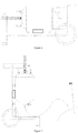
- the specific steps for seed culture transferring to the fermenter include: opening the isolation valve and the off-gas regulating valve, adding water or an aqueous solution to the tank by way of filtration sterilization, thereafter closing the isolation valve and the off-gas regulating valve, putting down the main tank and performing the operation of rotary mixing continually until it is observed from the sight glass that most of the strains have been washed off. Afterwards, the main tank is put upright, the fastening screws are screwed off, and pins are inserted into the threaded hole of the beam, so that the whole main tank is suspended at a higher position.
- a seed culture transferring pipeline is connected between the discharge valve and the inoculating valve at the top of the fermenter, and steam with a temperature of not less than 121°C and a pressure of not less than 0.1 MPa (gauge pressure) is introduced thereto through the valves to sterilize the pipeline for at least 20 minutes.
- a compressed air pipeline is connected at the pipe joint and the compressed air with a pressure higher than that of the fermenter is introduced, the suspension of strains within the device is pressed into the fermenter.
- the seed culture transferring method can also be carried out according to the following steps: closing the off-gas regulating valve and the isolation valve after the seed culture transferring pipeline has been installed and sterilized, opening the discharge valve of the main tank and the inoculating valve at the top of the fermenter to make the main tank in air communication with the upper space of the fermenter, and then reducing the pressure of the fermenter, so that the suspension of strains can be transferred into the fermenter by use of differential pressure.
- the addition of water can be repeated for several times, such that the strains can be transferred into the fermenter as thoroughly as possible.
- the inoculating valve at the top of the fermenter is closed, and the seed culture transferring pipeline is removed.
- the step (1) of the method specifically comprises the following steps:
- the step (2) of the method specifically comprises the following steps:
- the present disclosure provides a use of the solid state biological reaction device as described in the first aspect in the culturing of a microorganism or solid state fermentation by employing the method as described in the second aspect.
- the reaction device of the present disclosure can not only be used for a large scale production of filamentous organism spores, but also for the general solid state culturing and solid state fermentation of a microorganism.
- the microorganism can be selected from but is not limited to filamentous organisms, yeasts or bacteria.
- Example1 A solid state biological reaction device
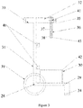
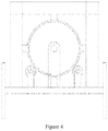
- the device comprises a main tank 1 and a lever-type trailer 2 which enables the main tank to rotate at a horizontal position and to achieve stationary culture at a vertical position; wherein, when the main tank 1 is in a horizontal position, the rotation of the main tank 1 can be achieved by manually movement or automatically driving via a driving device 49; and when the main tank 1 is at a vertical position, the main tank 1 is allowed to perform stationary culture, as shown in Figure 6 .
- the main tank 1 comprises an end cap 3, a cylinder 4 and a lower head 5 arranged from top to bottom; the end cap 3 comprises a rotary shaft 18 with a pin hole 19 disposed at the center of the top of the end cap 3, and an off-gas filter 6, a liquid filter 7 and an inoculation port 8 disposed on the end cap 3; an off-gas regulating valve 25 is disposed between the end cap 3 and the off-gas filter 6; an isolation valve 26 is disposed between the end cap 3 and the liquid filter 7.
- the cylinder 4 comprises a sight glass 9 disposed inside the cylinder 4 and a temperature sensor 10 disposed at the lower portion of the cylinder 4 and a temperature sensor casing 11 cased the temperature sensor 10; an upper spacing ring 20 is disposed along the top edge of the cylinder 4.
- the lower head 5 comprises a discharge valve 16 disposed in the middle of the bottom of the lower head 5 and an air inlet filter 15 disposed on the lower head 5; a check valve 17 is disposed between the air inlet filter 15 and the lower head 5; a pipe joint 24 is disposed at the upstream of the air inlet filter 15 for connecting the compressed air pipeline; and a lower spacing ring 21 is disposed along the top edge of the lower head 5.
- the interior of the main tank 1 comprises an upper screen plate 22 disposed at the internal junction of the end cap 3 and the cylinder 4, and a lower screen plate 23 disposed at the internal junction of the cylinder 4 and the lower head 5 to hold the position of the materials; the opening ratio of the screen plate 27 is 1-90%.
- the lever-type trailer comprises a base 29 and a pillar 31, an axle 28 is provided at the junction of the base 29 and the pillar 31, and the base 29 and the pillar 31 rotates along with the axle 28, and the axle 28 is provided with a wheel 39 at both ends respectively;
- the base 29 comprises a vertical supporting leg 34 and an annular supporting seat 30 disposed above the base 29 for supporting the main tank 1;
- the upper surface of the annular supporting seat 30 is provided with a sliding bearing 42.
- the pillar 31 comprises a horizontal supporting leg 33 and a beam 32 connected to the horizontal supporting leg 33 for connecting to the main tank 4, and a supporting wheel 40 disposed at the right side of the horizontal supporting leg 33 as a side wall support for the main tank 1 during horizontal placement and horizontal rotation.
- the beam 32 is provided with an upright through-hole 35 through which a sleeve 36 for fixing the rotary shaft 18 on the main tank 1 is provided; the beam 32 is provided with a horizontal threaded hole 41 perpendicularly intersecting with the through-hole 35 for mounting a fastening screw to fix the sleeve 36; the sleeve 36 is provided with a pin hole 1 (37) and a pin hole 2 (38) for mounting pins for fixing; the inner surface of the lower end of the sleeve 36 is provided with a sliding bearing 43.
- the method for using the device comprises the following steps:
- the screen plate 27 can also be disposed in the form of a plurality of layers distributed in the main tank 1, the ratio of the diameter of the opening area of the screen plate 27 to the outer diameter of the screen plate 27 is from 0.1 to 1, preferably from 0.5 to 0.9; the opening in the screen plate 27 can be a circular hole and/or an obround hole slot; the diameter of the circular hole is from 0.5 to 20 mm, preferably from 1 to 10 mm; the width of the obround hole slot is from 0.5 to 20 mm, preferably from 1 to 10 mm.
- the sight glass 9 has a circular shape or a stripe shape, preferably a stripe shape.
- the pore diameter of the off-gas filter 6, the liquid filter 7 and the air inlet filter 15 is from 0.2 to 0.22 ⁇ m, preferably 0.2 ⁇ m.
- a jacket 12 is disposed at the exterior of the cylinder 4, preferably the jacket 12 is disposed at the exterior of the cylinder 4 and the lower head 5, the jacket 12 comprises a water inlet pipe 13 disposed at the lower portion of the jacket 12 and a water outlet pipe 14 disposed at the upper portion of the jacket 12.
- the horizontal supporting leg 33 and the vertical supporting leg 34 may also be a caster wheel provided with a height adjusting means and a locking means.
- the material for making the main tank 1 and the carrier vehicle 2 is a material capable of withstanding steam of 121°C and 0.1 MPa, and can be selected from but is not limited to any one or a mixture of at least two of a stainless steel, a carbon steel, a nonferrous metal, a light alloy, a plastic, a glass lining or a glass.
- the end cap 3 has an elliptical, a spherical crown, a spherical, a dished or a plated shape, preferably an elliptical or a dished shape, and further preferably an elliptical shape.
- the lower head 5 has an elliptical, a spherical crown, a spherical, a dished or a tapered shape, preferably a tapered shape.
- the culturing of the spores of Aspergillus niger was performed by use of the device as described in Example 1 with the culturing procedure being the same as the culturing steps described in Example 1, and the components of the aqueous solution of the culture medium were as shown in Table 1, wherein the steps during the culturing were as follows:
- Corncob particles having a particle size range of 5-10 mm were placed in an excess amount of an aqueous solution of the culture medium and the components of the aqueous solution of the culture medium were shown in Table 1.
- the saturated corncob particles were bailed from the aqueous solution of the culture medium followed by being placed on the lower screen plate and spread out to obtain a bed of material with a thickness of 10 cm, then soaked at room temperature for 12 hours, the culturing procedure was the same as the culturing steps described in Example 1, and the specific parameters were as follows: introducing thermostatic circulating water of 35°C into the jacket continuously, keeping the culturing temperature at 35°C and an air flow at 0.5 L/min; putting down the main tank 1 for the first time to make it in a horizontal state, rotating the main tank 1 manually with a rotation speed of 10 rpm and keeping the rotation for 10 minutes; putting down the main tank 1 again to make it in the horizontal state when culturing for 48 hours and 96 hours, respectively, with a
- the culturing of the spores of Aspergillus sp. was performed by use of the device as described in Example 1 with the culturing procedure being the same as the culturing steps described in Example 1, and the components of the aqueous solution of the culture medium were as shown in Table 2, wherein the steps during the culturing were as follows:
- Corncob pieces having a particle size range of 10-20 mm were placed in an excess amount of an aqueous solution of the culture medium and the components of the aqueous solution of the culture medium were shown in Table 2.
- the saturated corncob pieces were bailed from the aqueous solution of the culture medium followed by being placed on the lower screen plate and spread out to obtain a bed of material with a thickness 20 cm, then soaked at room temperature for 12 hours, the culturing procedure was the same as the culturing steps described in Example 1, and the specific parameters were as follows: introducing thermostatic circulating water of 36°C into the jacket continuously, keeping the culturing temperature at 36°C and an air flow at 0.8 L/min; putting down the main tank 1 for the first time to make it in a horizontal state, rotating the main tank 1 by a rotary driving device 49 with a rotation speed of 10 rpm and keeping the rotation for 10 minutes; putting down the main tank 1 again to make it in the horizontal state when culturing for 36 hours and 72 hours,
- the culturing of Saccharomyces cerevisiae. was performed by use of the device as described in Example 1 with the culturing procedure being the same as the culturing and seed culture transferring steps described in Example 1, and the components of the aqueous solution of the culture medium were as shown in Table 3.
- the culturing of Bacillus subtilis. was performed by use of the device as described in Example 1 with the culturing procedure being the same as the culturing and seed culture transferring steps described in Example 1, and the components of the aqueous solution of the culture medium were as shown in Table 4.
- the shell of the tank was designed and manufactured according to the corresponding specifications of the special device pressure vessel, and a pressure gauge was installed additionally; (2) the vehicle was in the vertical state but was not put down when sterilization was performed; (3) steam with a temperature of 121°C and a gauge pressure of 0.1 MPa was introduced into the tank from the air inlet filter for 20 minutes when sterilization was performed, the sterilizer was not used; (4) the main tank 1 was automatically rotated by a rotary driving device; (4) the temperature of the jacket was 37°C during the culturing process; (5) the air flow introduced during the culturing process was controlled at 0.5 L/min; and (6) the culturing process was carried out for a total of 72 hours, wherein the rotary mixing was performed for 2 circles at 12 hours and 36 hours, respectively with a speed of 1 rpm.
- Table 4 Components Concentration (g/L) NaCl 10 Yeast extract 5 Peptone 10
- the device of the present disclosure is relatively simple, in particular a way of combining a vehicle-mounted tank with rotation is adopted for the mixing of the materials, which realizes the free rotation mixing of the tank in both the vertical attitude and the horizontal attitude;
- the screen plate of the device adopts a non-full-opening screen plate used to fix the position of the material and the strains when the main tank body is in a horizontal position, restricting the movement of the material and the strains so that the mixing of the material and the strains is more uniform;
- the device is not only fast-to-use and easy-to-move, but also eliminates the need for a mixing system which significantly saves the manufacturing costs of the device.
Landscapes
- Life Sciences & Earth Sciences (AREA)
- Health & Medical Sciences (AREA)
- Chemical & Material Sciences (AREA)
- Engineering & Computer Science (AREA)
- Bioinformatics & Cheminformatics (AREA)
- Wood Science & Technology (AREA)
- Organic Chemistry (AREA)
- Zoology (AREA)
- Genetics & Genomics (AREA)
- Biotechnology (AREA)
- Biochemistry (AREA)
- Microbiology (AREA)
- Biomedical Technology (AREA)
- General Engineering & Computer Science (AREA)
- General Health & Medical Sciences (AREA)
- Sustainable Development (AREA)
- Medicinal Chemistry (AREA)
- Mycology (AREA)
- Virology (AREA)
- Tropical Medicine & Parasitology (AREA)
- Clinical Laboratory Science (AREA)
- Botany (AREA)
- Molecular Biology (AREA)
- Thermal Sciences (AREA)
- Analytical Chemistry (AREA)
- Physics & Mathematics (AREA)
- Immunology (AREA)
- Apparatus Associated With Microorganisms And Enzymes (AREA)
Claims (15)
- Biologische Festkörperreaktionsvorrichtung mit einem Haupttank (1), wobei die Vorrichtung ferner eine Stütze (2) zum Stützen des Haupttanks (1) aufweist, die Stütze (2) ein Trägerfahrzeug ist, das Trägerfahrzeug eine Basis (29) und eine Säule (31) aufweist, ein Rad (39) an der Verbindung der Basis (29) und der Säule (31) vorgesehen ist, und die Basis (29) und die Säule (31) als Ganzes sich um die Achse des Rades (39) drehen können, was eine räumliche Lageänderung des Haupttanks (1) zwischen einer horizontalen Position und einer vertikalen Position ermöglicht, wobei der Haupttank (1) in der horizontalen Position rotieren kann und in der vertikalen Position für eine stationäre Kultur verwendet werden kann.
- Biologische Festkörperreaktionsvorrichtung nach Anspruch 1, wobei eine Drehwelle (18) in der Mitte der Oberseite des Haupttanks (1) angeordnet ist;die Stütze (2) einen Träger (32) zur Verbindung mit der Drehwelle (18) des Hauptbehälters (1) aufweist;die Stütze (2) mit einem Stützsitz (30) zum Abstützen des Haupttanks (1) versehen ist.
- Biologische Festkörperreaktionsvorrichtung nach Anspruch 1 oder 2, bei der im Inneren des Hauptbehälters mindestens eine Siebplatte (27) zum Halten der Position von Materialien angeordnet ist.
- Biologische Festkörperreaktionsvorrichtung nach Anspruch 3, wobei die Siebplatte ein Öffnungsverhältnis von 1 bis 90 %, vorzugsweise von 1 % bis 60 %, aufweist.
- Biologische Festkörperreaktionsvorrichtung nach Anspruch 3, wobei das Verhältnis des Durchmessers der Öffnungsfläche der Siebplatte zum Außendurchmesser der Siebplatte 0,1 bis 1, vorzugsweise 0,5 bis 0,9 beträgt.
- Biologische Festkörperreaktionsvorrichtung nach Anspruch 3, wobei die Öffnung in der Siebplatte ein kreisförmiges Loch und/oder ein Schlitz in Form eines Langlochs ist.
- Biologische Festkörperreaktionsvorrichtung nach Anspruch 6, wobei der Durchmesser des kreisförmigen Lochs von 0,2 bis 20 mm, vorzugsweise von 0,5 bis 3 mm, beträgt.
- Biologische Festkörperreaktionsvorrichtung nach Anspruch 6, wobei die Breite des Schlitzes in Form eines Langlochs von 0,2 bis 20 mm, vorzugsweise von 0,5 bis 3 mm, beträgt.
- Biologische Festkörperreaktionsvorrichtung nach einem der Ansprüche 1-8,wobei der Hauptbehälter von oben nach unten angeordnet eine Endkappe (3), einen Zylinder (4) und einen unteren Kopf (5) aufweist;die Endkappe (3) eine Drehwelle (18) mit einem Stiftloch (19), das in der Mitte der Oberseite der Endkappe (3) angeordnet ist, und einen Abgasfilter (6), einen Flüssigkeitsfilter (7) und eine Impföffnung (8), die an der Endkappe (3) angeordnet sind, aufweist;der Zylinder (4) ein Schauglas (9), das an der Innenwand des Zylinders (4) angeordnet ist, und einen Temperatursensor (10), der am unteren Teil des Zylinders (4) angeordnet ist, sowie ein Temperatursensorgehäuse (11), das den Temperatursensor (10) umgibt, aufweist;der untere Kopf (5) ein in der Mitte des Bodens des unteren Kopfes (5) angeordnetes Auslassventil (16) und einen am unteren Kopf (5) angeordneten Lufteinlassfilter (15) aufweist;vorzugsweise ein Rückschlagventil (17) zwischen dem Lufteinlassfilter (15) und dem unteren Kopf (5) angeordnet ist;vorzugsweise stromaufwärts des Lufteintrittsfilters (15) eine Rohrverbindung (24) zum Anschluss der Druckluftleitung angeordnet ist;vorzugsweise der Porendurchmesser des Abgasfilters (6), des Flüssigkeitsfilters (7) und des Lufteinlassfilters (15) 0,1 bis 0,22 µm, vorzugsweise 0,2 µm, beträgt.
- Biologische Festkörperreaktionsvorrichtung nach einem der Ansprüche 1-9,wobei der Hauptbehälter (1) eine obere Siebplatte (22) aufweist, die an der inneren Verbindung der Endkappe (3) und des Zylinders (4) angeordnet ist, und eine untere Siebplatte (23) aufweist, die an der inneren Verbindung des Zylinders (4) und des unteren Kopfes (5) angeordnet ist;vorzugsweise ein oberer Abstandsring (20) entlang der Oberkante des Zylinders (4) und ein unterer Abstandsring (21) entlang der Oberkante des unteren Kopfes (5) angeordnet ist;vorzugsweise ein Mantel (12) an der Außenseite des Zylinders (4) angeordnet ist, vorzugsweise ein Mantel (12) an der Außenseite des Zylinders (4) und des unteren Kopfes (5) angeordnet ist, wobei der Mantel (12) ein Wassereinlassrohr (13), das an dem unteren Abschnitt des Mantels (12) angeordnet ist, und ein Wasserauslassrohr (14), das an dem oberen Abschnitt des Mantels (12) angeordnet ist, aufweist;vorzugsweise ein Abgasregelventil (25) zwischen der Endkappe (3) und dem Abgasfilter (6) angeordnet ist;vorzugsweise ein Absperrventil (26) zwischen der Endkappe (3) und dem Flüssigkeitsfilter (7) angeordnet ist.
- Biologische Festkörperreaktionsvorrichtung nach einem der Ansprüche 1-10, wobei das Trägerfahrzeug ein Rollwagen ist;die Basis (29) ein vertikales Stützbein (34) und einen ringförmigen Stützsitz (30) aufweist, der oberhalb der Basis (29) angeordnet ist, um den Haupttank (1) zu stützen;die Säule (31) einen horizontalen Stützschenkel (33) und einen mit dem horizontalen Stützschenkel (33) verbundenen Träger (32) zur Verbindung mit dem Haupttank (1) aufweist;vorzugsweise die obere Fläche des ringförmigen Stützsitzes (30) mit einem Gleitlager (42) versehen ist;vorzugsweise an der Innenseite der Säule (31) ein Stützrad (40) als Seitenwandabstützung für den Haupttank (1) bei horizontaler Aufstellung und horizontaler Drehung angeordnet ist;vorzugsweise an der Innenseite der Säule (31) eine Drehantriebsvorrichtung (49) angeordnet ist, um den Haupttank (1) in Drehung zu versetzen;vorzugsweise der Träger (32) mit einer aufrechten Durchgangsbohrung (35) versehen ist, durch die eine Hülse (36) zur Befestigung der Drehwelle (18) am Haupttank (1) vorgesehen ist;vorzugsweise der Träger (32) mit einem horizontalen Gewindeloch (41) versehen ist, das sich senkrecht mit dem Durchgangsloch (35) schneidet, um eine Befestigungsschraube zur Befestigung der Hülse (36) anzubringen;vorzugsweise die Hülse (36) mit einem ersten Stiftloch (37) und einem zweiten Stiftloch (38) zur Befestigung von festen Stiften versehen ist;vorzugsweise die Innenfläche des unteren Endes der Hülse (36) mit einem Gleitlager (43) versehen ist.
- Biologische Festkörperreaktionsvorrichtung nach einem der Ansprüche 1-11, wobei das Material für die Herstellung des Hauptbehälters (1) und der Stütze (2) eines oder eine Mischung aus mindestens zwei der folgenden Materialien ist: rostfreier Stahl, Kohlenstoffstahl, Nichteisenmetall, Leichtmetall, Kunststoff, Glasauskleidung oder Glas;vorzugsweise die Endkappe (3) eine elliptische, eine kugelförmige, eine sphärische, eine gewölbte oder eine plattierte Form, vorzugsweise eine elliptische oder eine gewölbte Form, und weiter vorzugsweise eine elliptische Form, hat;vorzugsweise der untere Kopf (5) eine elliptische, eine kugelförmige, eine kugelige, eine gewölbte oder eine verjüngte Form, vorzugsweise eine verjüngte Form, hat.
- Verfahren zur Festkörperkultur eines Mikroorganismus, wobei die biologische Festkörperreaktionsvorrichtung nach einem der Ansprüche 1-12 verwendet wird und das Verfahren die folgenden Schritte aufweist:(1) Einbringen einer körnigen Kulturmatrix, die mit Nährstoffkomponenten eines flüssigen Kulturmediums getränkt ist, in den Haupttank (1), dann Sterilisieren des Haupttanks (1);(2) Animpfen nach der Sterilisation, Abstellen des Haupttanks (1) in einen horizontalen Zustand, Drehen des Hauptbehälters (1) zur Rotationsmischung und anschließendes Aufrichten des Hauptbehälters (1) zur Durchführung einer thermostatischen Kultur;
wahlweise mehrfaches Mischen während der Kultivierungsperiode;(3) nach der Kultivierung Belüften, bis die Kultur vollständig getrocknet ist, und dann Versiegeln und Konservieren für die zukünftige Verwendung;
wahlweise Umpflanzen der nach der Kultivierung erhaltenen Kultur in einen Fermenter (48) zur Expansion der Kultur. - Verfahren nach Anspruch 13, wobei der Schritt (1) des Verfahrens insbesondere die folgenden Schritte aufweist:(1a) Öffnen der Endkappe (3) und Einbringen der körnigen Kulturmatrix, die vollständig mit Nährstoffkomponenten des flüssigen Kulturmediums getränkt ist, in den Haupttank (1), dann Schließen der Endkappe (3);(1b) Zusammensetzen und Befestigen des Haupttanks (1) und der Stütze (2): Festsetzen des unteren Distanzrings (21) des Hauptbehälters (1) mit dem Gleitlager (42) auf dem ringförmigen Stützsitz (30) des hebelartigen Anhängers (2), dann Durchführen der Hülse (36) nach unten durch das aufrechte Durchgangsloch (35) auf dem Träger (32), um die Drehwelle (18) des Hauptbehälters (1) aufzunehmen, Ausrichten des Stiftlochs (38) und Einsetzen eines Stifts, danach Einschrauben einer Befestigungsschraube in den Träger (32) durch das Gewindeloch (41) und Anziehen, um der Hülse (36) standzuhalten, um die Hülse (36) und den Träger (32) als Ganzes festzuziehen;(1c) Ablegen des Haupttanks (1) in einen horizontalen Zustand zusammen mit dem Rollwagen (2), Öffnen des Abgasregulierventils (25) und des Absperrventils (26) zur Sterilisation;Wobei der Schritt (2) des Verfahrens vorzugsweise insbesondere die folgenden Schritte auf weist:(2a) nach der Sterilisation Einführen einer Druckluftleitung an der Rohrverbindung (24), Durchblasen des Lufteintrittsfilters (15), des Abgasfilters (6) und des Flüssigkeitsfilters (7) durch Einleiten von Druckluft, zwischenzeitliches Abkühlen der Kulturmatrix, Schließen des Absperrventils (26), geringfügiges Öffnen des Abgasregelventils (25) und Beimpfen von flüssigen Stämmen des zu kultivierenden Mikroorganismus durch die Impföffnung (8) unter Flammenschutz;(2b) nach der Beimpfung, Absetzen des Haupttanks (1) in einen horizontalen Zustand zusammen mit dem Rollwagen (2), Herausziehen des Stifts aus dem Stiftloch (38), Drehen des Haupttanks (1), so dass die Materialien im Tank gründlich mit den beimpften Flüssigkeitsstämmen gemischt werden;(2c) Wiedereinsetzen des Stifts nach dem Mischen, Aufrichten des Haupttanks (1) und Einleiten von Druckluft für die Kultivierung, dann Einleiten von thermostatischem Wasser mit der gleichen Temperatur wie die Temperatur der Kultur in den Mantel (12) durch das Wassereinlassrohr (13) und das Wasserauslassrohr (14), um die Temperatur der Kultur aufrechtzuerhalten;(2d) intermittierendes Abstellen des Haupttanks (1) während des Kultivierungsprozesses, wobei das Rotationsmischen mehrmals wiederholt wird;wahlweise, nach der Kultivierung, Einleiten von Druckluft durch die Rohrverbindung, um die Kultur zu trocknen.
- Verwendung der biologischen Festkörperreaktionsvorrichtung nach einem der Ansprüche 1 bis 12 bei der Kultivierung eines Mikroorganismus oder der Festkörperfermentation durch Anwendung des Verfahrens nach einem der Ansprüche 13 bis 14.
Applications Claiming Priority (2)
| Application Number | Priority Date | Filing Date | Title |
|---|---|---|---|
| CN201510474799.2A CN106701549B (zh) | 2015-08-06 | 2015-08-06 | 一种固态生物反应装置、使用方法及其应用 |
| PCT/CN2016/093267 WO2017020853A1 (zh) | 2015-08-06 | 2016-08-04 | 一种固态生物反应装置、使用方法及其应用 |
Publications (3)
| Publication Number | Publication Date |
|---|---|
| EP3333252A1 EP3333252A1 (de) | 2018-06-13 |
| EP3333252A4 EP3333252A4 (de) | 2019-03-27 |
| EP3333252B1 true EP3333252B1 (de) | 2021-10-27 |
Family
ID=57942437
Family Applications (1)
| Application Number | Title | Priority Date | Filing Date |
|---|---|---|---|
| EP16832341.8A Not-in-force EP3333252B1 (de) | 2015-08-06 | 2016-08-04 | Biologische festkörperreaktionsvorrichtung, verwendungsverfahren und verwendung davon |
Country Status (4)
| Country | Link |
|---|---|
| US (1) | US10851334B2 (de) |
| EP (1) | EP3333252B1 (de) |
| CN (1) | CN106701549B (de) |
| WO (1) | WO2017020853A1 (de) |
Families Citing this family (13)
| Publication number | Priority date | Publication date | Assignee | Title |
|---|---|---|---|---|
| CN107347445A (zh) * | 2017-07-24 | 2017-11-17 | 江苏沿江地区农业科学研究所 | 利用杏鲍菇菌糠生产双孢蘑菇颗粒菌种的方法 |
| CN108707541B (zh) * | 2018-06-25 | 2021-06-25 | 济宁滨阳生物科技股份有限公司 | 一种微生物发酵装置 |
| CN110170180B (zh) * | 2019-04-18 | 2021-09-10 | 广东省测试分析研究所(中国广州分析测试中心) | 一种固体废物/土壤中重金属浸出毒性的恒温浸提/萃取抽滤装置 |
| CN110013492B (zh) * | 2019-04-26 | 2021-04-16 | 安徽利民生物科技股份有限公司 | 一种超微灵芝孢子粉制备系统 |
| CN110218638A (zh) * | 2019-07-02 | 2019-09-10 | 大连富森智能科技有限公司 | 一种菌种发酵罐 |
| CN111893030B (zh) * | 2020-08-10 | 2023-09-08 | 惠农达生物技术(江苏)有限公司 | 一种固态发酵液体菌种接种装置 |
| CN112704068A (zh) * | 2020-12-25 | 2021-04-27 | 常州胜杰生命科技股份有限公司 | 新型绿色s-烯虫酯可湿性粉剂及其制备方法和应用 |
| CN113046292B (zh) * | 2021-04-02 | 2022-06-28 | 山东安然纳米实业发展有限公司 | 一种利用生物反应装置培养人参干细胞的方法 |
| CN113025555B (zh) * | 2021-04-20 | 2023-01-24 | 山东安然纳米实业发展有限公司 | 一种利用生物反应装置分离培养人参干细胞的方法 |
| CN112920986B (zh) * | 2021-04-20 | 2023-02-07 | 山东安然纳米实业发展有限公司 | 一种利用人参干细胞发酵生产人参皂苷的方法 |
| CN113403058A (zh) * | 2021-05-27 | 2021-09-17 | 濮阳市万良石油科技发展有限公司 | 一种增效剂及其制备方法 |
| CN116536169A (zh) * | 2023-05-16 | 2023-08-04 | 禹沐源生物科技(重庆)有限公司 | 一种新型碳源培菌剂、制备方法及其制备系统 |
| CN118344957B (zh) * | 2024-06-18 | 2024-09-03 | 名佑(福建)食品有限公司 | 一种培根加工用发酵处理装置及其发酵方法 |
Citations (1)
| Publication number | Priority date | Publication date | Assignee | Title |
|---|---|---|---|---|
| CN104522514A (zh) * | 2014-12-25 | 2015-04-22 | 东莞市双红生物转化技术有限公司 | 固态发酵罐及利用该固态发酵罐制备红曲米的方法及其制品 |
Family Cites Families (24)
| Publication number | Priority date | Publication date | Assignee | Title |
|---|---|---|---|---|
| US4613433A (en) * | 1982-12-24 | 1986-09-23 | Biomass Limited | Anaerobic fermentor |
| AT387234B (de) | 1987-03-05 | 1988-12-27 | Vogelbusch Gmbh | Vorrichtung zur zuechtung von dauerformen insbesondere filamentoeser mikroorganismen |
| US5057221A (en) | 1988-12-19 | 1991-10-15 | Weyerhaeuser Company | Aerobic biological dehalogenation reactor |
| US5300438A (en) * | 1992-07-06 | 1994-04-05 | Augspurger Engineering | Composting apparatus |
| US5494574A (en) | 1994-08-09 | 1996-02-27 | Envirogen, Inc. | Mechanically mixed packed bed bioreactor |
| CA2304266A1 (en) | 1999-04-02 | 2000-10-02 | Norman L. Arrison | Apparatus and process for separating fluids and particles |
| US6752926B2 (en) | 2000-10-20 | 2004-06-22 | Trustees Of Stevens Institute Of Technology | Method and apparatus for treatment of wastewater |
| JP4200655B2 (ja) | 2000-12-26 | 2008-12-24 | 味の素株式会社 | 焼結金属膜を用いた好気的培養方法 |
| CN1219874C (zh) * | 2002-08-09 | 2005-09-21 | 中国科学院过程工程研究所 | 固态发酵无菌操作的发酵装置 |
| CN100344744C (zh) | 2005-11-18 | 2007-10-24 | 沈阳农业大学 | 固态发酵真菌孢子分离器及分离方法 |
| CN101177693B (zh) * | 2006-11-08 | 2011-04-06 | 中国科学院过程工程研究所 | 一种连续耦合的固态发酵方法及生物反应装置 |
| CN201087969Y (zh) * | 2007-04-06 | 2008-07-16 | 新疆大学 | 滚筒式固态物料的微波连续加热装置 |
| CN101220378B (zh) * | 2008-01-30 | 2010-09-01 | 清华大学 | 一种基于糖质原料生产乙醇的固态发酵方法与系统 |
| CN101503713B (zh) | 2009-03-11 | 2011-12-28 | 清华大学 | 糖质原料生产乙醇发酵/蒸馏一体化工艺及装置 |
| CN101524672B (zh) | 2009-04-13 | 2010-09-08 | 浙江大学 | 旋风分离器和带有该旋风分离器的孢子分离装置 |
| CN201545827U (zh) | 2009-10-23 | 2010-08-11 | 江苏省农业科学院 | 气流悬浮式真菌孢子分离器 |
| RU2603754C2 (ru) | 2012-06-06 | 2016-11-27 | Новозимс Биоаг А/С | Промышленный твердофазный биореактор, промышленная твердофазная биореакторная система. |
| CN102924146B (zh) * | 2012-12-03 | 2014-05-07 | 北京科技大学 | 一种可移动转鼓式堆肥反应器 |
| CN103911282A (zh) * | 2013-01-06 | 2014-07-09 | 北大工学院绍兴技术研究院 | 一种发酵装置 |
| CN103509712B (zh) * | 2013-08-07 | 2015-11-18 | 清华大学 | 一种具备自控系统的连续固态发酵制取乙醇的装置及工艺 |
| CN104630020B (zh) | 2013-11-07 | 2016-08-24 | 中国科学院天津工业生物技术研究所 | 一种固态生物反应装置和用该装置制备丝状菌孢子的方法 |
| CN203559041U (zh) * | 2013-11-12 | 2014-04-23 | 山西戎子酒庄有限公司 | 可移动葡萄酒发酵罐 |
| CN103911862B (zh) | 2014-03-24 | 2016-03-23 | 福建鑫华股份有限公司 | 一种浮油清除材料及其制备方法 |
| CN104403986A (zh) * | 2014-11-07 | 2015-03-11 | 德州创迪微生物资源有限责任公司 | 一种微生物孢子的培养方法及设备 |
-
2015
- 2015-08-06 CN CN201510474799.2A patent/CN106701549B/zh not_active Expired - Fee Related
-
2016
- 2016-08-04 WO PCT/CN2016/093267 patent/WO2017020853A1/zh not_active Ceased
- 2016-08-04 EP EP16832341.8A patent/EP3333252B1/de not_active Not-in-force
- 2016-08-04 US US15/750,126 patent/US10851334B2/en not_active Expired - Fee Related
Patent Citations (1)
| Publication number | Priority date | Publication date | Assignee | Title |
|---|---|---|---|---|
| CN104522514A (zh) * | 2014-12-25 | 2015-04-22 | 东莞市双红生物转化技术有限公司 | 固态发酵罐及利用该固态发酵罐制备红曲米的方法及其制品 |
Also Published As
| Publication number | Publication date |
|---|---|
| EP3333252A4 (de) | 2019-03-27 |
| CN106701549B (zh) | 2020-07-14 |
| US20180223235A1 (en) | 2018-08-09 |
| WO2017020853A1 (zh) | 2017-02-09 |
| EP3333252A1 (de) | 2018-06-13 |
| CN106701549A (zh) | 2017-05-24 |
| US10851334B2 (en) | 2020-12-01 |
Similar Documents
| Publication | Publication Date | Title |
|---|---|---|
| US10851334B2 (en) | Solid state biological reaction device, usage method and use thereof | |
| US6620614B1 (en) | Solid-state fermenter and method for solid-state fermentation | |
| JP2002513557A5 (de) | ||
| CN102443535A (zh) | 一种固态发酵生物反应器 | |
| US20160369226A1 (en) | Solid-state biological reaction device and method for preparing filamentous organism spores by using the same | |
| CN103204615B (zh) | 养殖粪便的发酵工艺 | |
| CN105695341B (zh) | 一种用于黑曲霉扩大培养的麸曲培养基及培养方法 | |
| WO2016172998A1 (zh) | 植物生物反应器及其使用方法 | |
| CN205275598U (zh) | 一种新型厌氧菌培养皿 | |
| CN102191276A (zh) | 呼吸式固态发酵方法及发酵罐 | |
| US20150197718A1 (en) | Bioreactor to obtain bioactive substances through solid-state fermentation using macromycetes fungi | |
| CN209836026U (zh) | 一种可移动的固体微生物肥料发酵仓 | |
| HK1236219A1 (en) | Soild state biological reaction device, use method and application thereof | |
| HK1236219A (en) | Soild state biological reaction device, use method and application thereof | |
| CN105420130A (zh) | 一种饲用酿酒酵母液固两相发酵方法 | |
| TWI409329B (zh) | Microbial solid - state fermentation reaction system with energy - saving and multi - functional automated production module | |
| CN204151338U (zh) | 一种黑曲霉发酵培养液取样器 | |
| CN212581887U (zh) | 一种气动搅拌发酵罐和配套设施 | |
| HK1236219B (en) | Soild state biological reaction device, use method and application thereof | |
| CN101061780A (zh) | 培养基通氧发酵及菌丝培养仓 | |
| CN213803747U (zh) | 一种生物菌剂生产用的发酵罐 | |
| CN223688323U (zh) | 一种土壤微生物生物量测定前处理装置 | |
| CN201024175Y (zh) | 空心球体式灭菌冷却接种发酵器 | |
| CN104962502A (zh) | 一种用于污泥处理的复合微生物菌剂及其制备方法 | |
| CN222455019U (zh) | 一种实验室用固态饲料发酵装置 |
Legal Events
| Date | Code | Title | Description |
|---|---|---|---|
| STAA | Information on the status of an ep patent application or granted ep patent |
Free format text: STATUS: THE INTERNATIONAL PUBLICATION HAS BEEN MADE |
|
| PUAI | Public reference made under article 153(3) epc to a published international application that has entered the european phase |
Free format text: ORIGINAL CODE: 0009012 |
|
| STAA | Information on the status of an ep patent application or granted ep patent |
Free format text: STATUS: REQUEST FOR EXAMINATION WAS MADE |
|
| 17P | Request for examination filed |
Effective date: 20180103 |
|
| AK | Designated contracting states |
Kind code of ref document: A1 Designated state(s): AL AT BE BG CH CY CZ DE DK EE ES FI FR GB GR HR HU IE IS IT LI LT LU LV MC MK MT NL NO PL PT RO RS SE SI SK SM TR |
|
| AX | Request for extension of the european patent |
Extension state: BA ME |
|
| DAV | Request for validation of the european patent (deleted) | ||
| DAX | Request for extension of the european patent (deleted) | ||
| A4 | Supplementary search report drawn up and despatched |
Effective date: 20190227 |
|
| RIC1 | Information provided on ipc code assigned before grant |
Ipc: C12N 1/00 20060101ALI20190221BHEP Ipc: C12M 1/16 20060101AFI20190221BHEP Ipc: C12M 1/04 20060101ALI20190221BHEP |
|
| STAA | Information on the status of an ep patent application or granted ep patent |
Free format text: STATUS: EXAMINATION IS IN PROGRESS |
|
| 17Q | First examination report despatched |
Effective date: 20200224 |
|
| GRAP | Despatch of communication of intention to grant a patent |
Free format text: ORIGINAL CODE: EPIDOSNIGR1 |
|
| STAA | Information on the status of an ep patent application or granted ep patent |
Free format text: STATUS: GRANT OF PATENT IS INTENDED |
|
| INTG | Intention to grant announced |
Effective date: 20210813 |
|
| GRAS | Grant fee paid |
Free format text: ORIGINAL CODE: EPIDOSNIGR3 |
|
| GRAA | (expected) grant |
Free format text: ORIGINAL CODE: 0009210 |
|
| STAA | Information on the status of an ep patent application or granted ep patent |
Free format text: STATUS: THE PATENT HAS BEEN GRANTED |
|
| AK | Designated contracting states |
Kind code of ref document: B1 Designated state(s): AL AT BE BG CH CY CZ DE DK EE ES FI FR GB GR HR HU IE IS IT LI LT LU LV MC MK MT NL NO PL PT RO RS SE SI SK SM TR |
|
| REG | Reference to a national code |
Ref country code: GB Ref legal event code: FG4D |
|
| REG | Reference to a national code |
Ref country code: CH Ref legal event code: EP |
|
| REG | Reference to a national code |
Ref country code: AT Ref legal event code: REF Ref document number: 1441817 Country of ref document: AT Kind code of ref document: T Effective date: 20211115 |
|
| REG | Reference to a national code |
Ref country code: DE Ref legal event code: R096 Ref document number: 602016065524 Country of ref document: DE |
|
| REG | Reference to a national code |
Ref country code: IE Ref legal event code: FG4D |
|
| REG | Reference to a national code |
Ref country code: LT Ref legal event code: MG9D |
|
| REG | Reference to a national code |
Ref country code: NL Ref legal event code: MP Effective date: 20211027 |
|
| REG | Reference to a national code |
Ref country code: AT Ref legal event code: MK05 Ref document number: 1441817 Country of ref document: AT Kind code of ref document: T Effective date: 20211027 |
|
| PG25 | Lapsed in a contracting state [announced via postgrant information from national office to epo] |
Ref country code: RS Free format text: LAPSE BECAUSE OF FAILURE TO SUBMIT A TRANSLATION OF THE DESCRIPTION OR TO PAY THE FEE WITHIN THE PRESCRIBED TIME-LIMIT Effective date: 20211027 Ref country code: LT Free format text: LAPSE BECAUSE OF FAILURE TO SUBMIT A TRANSLATION OF THE DESCRIPTION OR TO PAY THE FEE WITHIN THE PRESCRIBED TIME-LIMIT Effective date: 20211027 Ref country code: FI Free format text: LAPSE BECAUSE OF FAILURE TO SUBMIT A TRANSLATION OF THE DESCRIPTION OR TO PAY THE FEE WITHIN THE PRESCRIBED TIME-LIMIT Effective date: 20211027 Ref country code: BG Free format text: LAPSE BECAUSE OF FAILURE TO SUBMIT A TRANSLATION OF THE DESCRIPTION OR TO PAY THE FEE WITHIN THE PRESCRIBED TIME-LIMIT Effective date: 20220127 Ref country code: AT Free format text: LAPSE BECAUSE OF FAILURE TO SUBMIT A TRANSLATION OF THE DESCRIPTION OR TO PAY THE FEE WITHIN THE PRESCRIBED TIME-LIMIT Effective date: 20211027 |
|
| PG25 | Lapsed in a contracting state [announced via postgrant information from national office to epo] |
Ref country code: IS Free format text: LAPSE BECAUSE OF FAILURE TO SUBMIT A TRANSLATION OF THE DESCRIPTION OR TO PAY THE FEE WITHIN THE PRESCRIBED TIME-LIMIT Effective date: 20220227 Ref country code: SE Free format text: LAPSE BECAUSE OF FAILURE TO SUBMIT A TRANSLATION OF THE DESCRIPTION OR TO PAY THE FEE WITHIN THE PRESCRIBED TIME-LIMIT Effective date: 20211027 Ref country code: PT Free format text: LAPSE BECAUSE OF FAILURE TO SUBMIT A TRANSLATION OF THE DESCRIPTION OR TO PAY THE FEE WITHIN THE PRESCRIBED TIME-LIMIT Effective date: 20220228 Ref country code: PL Free format text: LAPSE BECAUSE OF FAILURE TO SUBMIT A TRANSLATION OF THE DESCRIPTION OR TO PAY THE FEE WITHIN THE PRESCRIBED TIME-LIMIT Effective date: 20211027 Ref country code: NO Free format text: LAPSE BECAUSE OF FAILURE TO SUBMIT A TRANSLATION OF THE DESCRIPTION OR TO PAY THE FEE WITHIN THE PRESCRIBED TIME-LIMIT Effective date: 20220127 Ref country code: NL Free format text: LAPSE BECAUSE OF FAILURE TO SUBMIT A TRANSLATION OF THE DESCRIPTION OR TO PAY THE FEE WITHIN THE PRESCRIBED TIME-LIMIT Effective date: 20211027 Ref country code: LV Free format text: LAPSE BECAUSE OF FAILURE TO SUBMIT A TRANSLATION OF THE DESCRIPTION OR TO PAY THE FEE WITHIN THE PRESCRIBED TIME-LIMIT Effective date: 20211027 Ref country code: HR Free format text: LAPSE BECAUSE OF FAILURE TO SUBMIT A TRANSLATION OF THE DESCRIPTION OR TO PAY THE FEE WITHIN THE PRESCRIBED TIME-LIMIT Effective date: 20211027 Ref country code: GR Free format text: LAPSE BECAUSE OF FAILURE TO SUBMIT A TRANSLATION OF THE DESCRIPTION OR TO PAY THE FEE WITHIN THE PRESCRIBED TIME-LIMIT Effective date: 20220128 Ref country code: ES Free format text: LAPSE BECAUSE OF FAILURE TO SUBMIT A TRANSLATION OF THE DESCRIPTION OR TO PAY THE FEE WITHIN THE PRESCRIBED TIME-LIMIT Effective date: 20211027 |
|
| REG | Reference to a national code |
Ref country code: DE Ref legal event code: R097 Ref document number: 602016065524 Country of ref document: DE |
|
| PG25 | Lapsed in a contracting state [announced via postgrant information from national office to epo] |
Ref country code: SM Free format text: LAPSE BECAUSE OF FAILURE TO SUBMIT A TRANSLATION OF THE DESCRIPTION OR TO PAY THE FEE WITHIN THE PRESCRIBED TIME-LIMIT Effective date: 20211027 Ref country code: SK Free format text: LAPSE BECAUSE OF FAILURE TO SUBMIT A TRANSLATION OF THE DESCRIPTION OR TO PAY THE FEE WITHIN THE PRESCRIBED TIME-LIMIT Effective date: 20211027 Ref country code: RO Free format text: LAPSE BECAUSE OF FAILURE TO SUBMIT A TRANSLATION OF THE DESCRIPTION OR TO PAY THE FEE WITHIN THE PRESCRIBED TIME-LIMIT Effective date: 20211027 Ref country code: EE Free format text: LAPSE BECAUSE OF FAILURE TO SUBMIT A TRANSLATION OF THE DESCRIPTION OR TO PAY THE FEE WITHIN THE PRESCRIBED TIME-LIMIT Effective date: 20211027 Ref country code: DK Free format text: LAPSE BECAUSE OF FAILURE TO SUBMIT A TRANSLATION OF THE DESCRIPTION OR TO PAY THE FEE WITHIN THE PRESCRIBED TIME-LIMIT Effective date: 20211027 Ref country code: CZ Free format text: LAPSE BECAUSE OF FAILURE TO SUBMIT A TRANSLATION OF THE DESCRIPTION OR TO PAY THE FEE WITHIN THE PRESCRIBED TIME-LIMIT Effective date: 20211027 |
|
| PLBE | No opposition filed within time limit |
Free format text: ORIGINAL CODE: 0009261 |
|
| STAA | Information on the status of an ep patent application or granted ep patent |
Free format text: STATUS: NO OPPOSITION FILED WITHIN TIME LIMIT |
|
| 26N | No opposition filed |
Effective date: 20220728 |
|
| PG25 | Lapsed in a contracting state [announced via postgrant information from national office to epo] |
Ref country code: AL Free format text: LAPSE BECAUSE OF FAILURE TO SUBMIT A TRANSLATION OF THE DESCRIPTION OR TO PAY THE FEE WITHIN THE PRESCRIBED TIME-LIMIT Effective date: 20211027 |
|
| PGFP | Annual fee paid to national office [announced via postgrant information from national office to epo] |
Ref country code: GB Payment date: 20220822 Year of fee payment: 7 |
|
| PG25 | Lapsed in a contracting state [announced via postgrant information from national office to epo] |
Ref country code: SI Free format text: LAPSE BECAUSE OF FAILURE TO SUBMIT A TRANSLATION OF THE DESCRIPTION OR TO PAY THE FEE WITHIN THE PRESCRIBED TIME-LIMIT Effective date: 20211027 |
|
| PGFP | Annual fee paid to national office [announced via postgrant information from national office to epo] |
Ref country code: FR Payment date: 20220823 Year of fee payment: 7 |
|
| REG | Reference to a national code |
Ref country code: DE Ref legal event code: R119 Ref document number: 602016065524 Country of ref document: DE |
|
| PG25 | Lapsed in a contracting state [announced via postgrant information from national office to epo] |
Ref country code: MC Free format text: LAPSE BECAUSE OF FAILURE TO SUBMIT A TRANSLATION OF THE DESCRIPTION OR TO PAY THE FEE WITHIN THE PRESCRIBED TIME-LIMIT Effective date: 20211027 |
|
| REG | Reference to a national code |
Ref country code: CH Ref legal event code: PL |
|
| PG25 | Lapsed in a contracting state [announced via postgrant information from national office to epo] |
Ref country code: LU Free format text: LAPSE BECAUSE OF NON-PAYMENT OF DUE FEES Effective date: 20220804 Ref country code: LI Free format text: LAPSE BECAUSE OF NON-PAYMENT OF DUE FEES Effective date: 20220831 Ref country code: CH Free format text: LAPSE BECAUSE OF NON-PAYMENT OF DUE FEES Effective date: 20220831 |
|
| REG | Reference to a national code |
Ref country code: BE Ref legal event code: MM Effective date: 20220831 |
|
| PG25 | Lapsed in a contracting state [announced via postgrant information from national office to epo] |
Ref country code: IT Free format text: LAPSE BECAUSE OF FAILURE TO SUBMIT A TRANSLATION OF THE DESCRIPTION OR TO PAY THE FEE WITHIN THE PRESCRIBED TIME-LIMIT Effective date: 20211027 |
|
| PG25 | Lapsed in a contracting state [announced via postgrant information from national office to epo] |
Ref country code: IE Free format text: LAPSE BECAUSE OF NON-PAYMENT OF DUE FEES Effective date: 20220804 Ref country code: DE Free format text: LAPSE BECAUSE OF NON-PAYMENT OF DUE FEES Effective date: 20230301 |
|
| PG25 | Lapsed in a contracting state [announced via postgrant information from national office to epo] |
Ref country code: BE Free format text: LAPSE BECAUSE OF NON-PAYMENT OF DUE FEES Effective date: 20220831 |
|
| PG25 | Lapsed in a contracting state [announced via postgrant information from national office to epo] |
Ref country code: HU Free format text: LAPSE BECAUSE OF FAILURE TO SUBMIT A TRANSLATION OF THE DESCRIPTION OR TO PAY THE FEE WITHIN THE PRESCRIBED TIME-LIMIT; INVALID AB INITIO Effective date: 20160804 |
|
| GBPC | Gb: european patent ceased through non-payment of renewal fee |
Effective date: 20230804 |
|
| PG25 | Lapsed in a contracting state [announced via postgrant information from national office to epo] |
Ref country code: MK Free format text: LAPSE BECAUSE OF FAILURE TO SUBMIT A TRANSLATION OF THE DESCRIPTION OR TO PAY THE FEE WITHIN THE PRESCRIBED TIME-LIMIT Effective date: 20211027 Ref country code: CY Free format text: LAPSE BECAUSE OF FAILURE TO SUBMIT A TRANSLATION OF THE DESCRIPTION OR TO PAY THE FEE WITHIN THE PRESCRIBED TIME-LIMIT Effective date: 20211027 |
|
| PG25 | Lapsed in a contracting state [announced via postgrant information from national office to epo] |
Ref country code: TR Free format text: LAPSE BECAUSE OF FAILURE TO SUBMIT A TRANSLATION OF THE DESCRIPTION OR TO PAY THE FEE WITHIN THE PRESCRIBED TIME-LIMIT Effective date: 20211027 |
|
| PG25 | Lapsed in a contracting state [announced via postgrant information from national office to epo] |
Ref country code: GB Free format text: LAPSE BECAUSE OF NON-PAYMENT OF DUE FEES Effective date: 20230804 |
|
| PG25 | Lapsed in a contracting state [announced via postgrant information from national office to epo] |
Ref country code: GB Free format text: LAPSE BECAUSE OF NON-PAYMENT OF DUE FEES Effective date: 20230804 Ref country code: FR Free format text: LAPSE BECAUSE OF NON-PAYMENT OF DUE FEES Effective date: 20230831 |
|
| PG25 | Lapsed in a contracting state [announced via postgrant information from national office to epo] |
Ref country code: MT Free format text: LAPSE BECAUSE OF FAILURE TO SUBMIT A TRANSLATION OF THE DESCRIPTION OR TO PAY THE FEE WITHIN THE PRESCRIBED TIME-LIMIT Effective date: 20211027 |