EP3332079B1 - Gebäudeelement und verfahren zur enteisung eines flächengebildes - Google Patents
Gebäudeelement und verfahren zur enteisung eines flächengebildes Download PDFInfo
- Publication number
- EP3332079B1 EP3332079B1 EP16745766.2A EP16745766A EP3332079B1 EP 3332079 B1 EP3332079 B1 EP 3332079B1 EP 16745766 A EP16745766 A EP 16745766A EP 3332079 B1 EP3332079 B1 EP 3332079B1
- Authority
- EP
- European Patent Office
- Prior art keywords
- planar structure
- building element
- building
- drive
- drive mechanism
- Prior art date
- Legal status (The legal status is an assumption and is not a legal conclusion. Google has not performed a legal analysis and makes no representation as to the accuracy of the status listed.)
- Active
Links
Images


Classifications
-
- E—FIXED CONSTRUCTIONS
- E06—DOORS, WINDOWS, SHUTTERS, OR ROLLER BLINDS IN GENERAL; LADDERS
- E06B—FIXED OR MOVABLE CLOSURES FOR OPENINGS IN BUILDINGS, VEHICLES, FENCES OR LIKE ENCLOSURES IN GENERAL, e.g. DOORS, WINDOWS, BLINDS, GATES
- E06B9/00—Screening or protective devices for wall or similar openings, with or without operating or securing mechanisms; Closures of similar construction
- E06B9/56—Operating, guiding or securing devices or arrangements for roll-type closures; Spring drums; Tape drums; Counterweighting arrangements therefor
-
- E—FIXED CONSTRUCTIONS
- E06—DOORS, WINDOWS, SHUTTERS, OR ROLLER BLINDS IN GENERAL; LADDERS
- E06B—FIXED OR MOVABLE CLOSURES FOR OPENINGS IN BUILDINGS, VEHICLES, FENCES OR LIKE ENCLOSURES IN GENERAL, e.g. DOORS, WINDOWS, BLINDS, GATES
- E06B9/00—Screening or protective devices for wall or similar openings, with or without operating or securing mechanisms; Closures of similar construction
- E06B9/02—Shutters, movable grilles, or other safety closing devices, e.g. against burglary
- E06B9/08—Roll-type closures
- E06B9/11—Roller shutters
- E06B9/15—Roller shutters with closing members formed of slats or the like
- E06B2009/1505—Slat details
-
- E—FIXED CONSTRUCTIONS
- E06—DOORS, WINDOWS, SHUTTERS, OR ROLLER BLINDS IN GENERAL; LADDERS
- E06B—FIXED OR MOVABLE CLOSURES FOR OPENINGS IN BUILDINGS, VEHICLES, FENCES OR LIKE ENCLOSURES IN GENERAL, e.g. DOORS, WINDOWS, BLINDS, GATES
- E06B9/00—Screening or protective devices for wall or similar openings, with or without operating or securing mechanisms; Closures of similar construction
- E06B9/56—Operating, guiding or securing devices or arrangements for roll-type closures; Spring drums; Tape drums; Counterweighting arrangements therefor
- E06B9/58—Guiding devices
- E06B2009/587—Mounting of guiding devices to supporting structure
Definitions
- the invention relates to a building element with a sheet, which is mounted to vibrate and / or is capable of surface vibrations. Furthermore, the invention relates to a method for deicing a fabric of a building element. Devices and methods of the type mentioned above can be used for example as a blind or external blinds in construction.
- window openings by moving blackout, anti-glare or sun protection devices.
- shutters, blinds or external blinds can be used.
- outside shading or darkening systems can freeze. This may affect the function in that the sunshade device or the blind is fixed in the current position. For example, this can no longer be rolled up and must therefore remain until the onset of thawing in front of the window opening.
- the rolled-up plate pack can freeze, so that the sun protection device or the blind can not be closed.
- de-icing may still be possible by the user from the outside, for example by applying a de-icing agent. At high window openings, however, this possibility does not exist.
- a roller door which has a flexible door leaf, which is wound on a rotatably mounted above a building opening Aufwickelwalze and which is guided laterally in guides, which are designed to be heated.
- lateral seals are formed as aprons, which rest at acute angles to the door leaf.
- the WO 2006/132478 A1 discloses a drive for a sunshade device with an ultrasonic motor. This can be provided with a control which allows manual operation and automatic operation, which controls the sun protection device as a function of time, day or weather.
- the invention is therefore an object of the invention to provide a building element and a method for deicing a fabric, which works reliably even in adverse weather conditions and regardless of the accessibility of the window opening.
- the object is achieved by a building element according to claim 1 and a method according to claim 9.
- the building element according to the invention has a fabric.
- the sheet may be composed of individual slats, as in a known roller shutter shell or a known blind or a known external blinds.
- the sheet may comprise or consist of a textile sunscreen.
- the term "sheet" is used for all these elements. This is intended to include embodiments in which individual lamellae or elements are spaced apart from each other so that the surface is not completely closed.
- the sheet can be used, for example, for temporarily closing or shading a window opening and, for example, be a blind, a Venetian blind or a shutter.
- the sheet may be part of a roll-up door closing, for example, a garage or a workshop.
- the sheet may be part of a glazing.
- the building element with a drive device with which the fabric is displaceable in forced oscillations. Due to the vibrations of the fabric, the mechanical bond between a layer of ice and the underlying surface of the fabric can be solved. The ice can thus be solved by vibrations of the fabric, so that the fabric is then again freely movable and can be either off or rolled or adjusted according to the wishes of the user.
- the drive device may be selected from at least one piezoelectric actuator and / or an eccentric drive and / or an electromagnetic drive.
- An eccentric for example, with electrical or mechanical Drive means are provided to exert a periodic force on the sheet or its attachment.
- a mechanical eccentric drive for example via a crank, can be used by the user without auxiliary electrical energy and is therefore also suitable for use in remote locations or for use in vehicles with limited energy resources.
- a piezo drive can provide high frequencies and high actuating forces in a compact design.
- An electromagnetic drive may include an AC powered coil that applies a cyclic force to a core, much like a speaker drive.
- the drive device can be controlled by an electronic control device.
- the control device can activate the drive device either weather-guided, if an icing of the surface element is to expect.
- the control device can activate the drive device when icing has been detected, for example by responding to an overload protection of a roller shutter drive or depending on the measured values of an icing sensor.
- the drive means may be manually activated by user intervention when the user has detected icing of the sheet.
- the sheet may be selected from a roller shutter and / or a roller shutter door and / or a glazing and / or a membrane roof and / or a carriageway.
- a roller shutter and / or a roller shutter door and / or a glazing and / or a membrane roof and / or a carriageway By removing glaciation from a glazing, the free view through the window of a building can be ensured. In the case of shop windows, of course, an unhindered view into the building can be made possible.
- the removal of snow and ice deposits from membrane roofs or Glazing can reduce the building load, making it easier to measure the statics of the building. In the same way aircraft wings, wings of wind turbines or overhead lines of ice and snow can be freed.
- the sheet may comprise a roller shutter or a roller shutter, which are guided on at least one edge in at least one guide rail or by guide rollers, which is fastened to the building by means of an elastic element.
- the drive device can engage the guide rail and cause the sheet to vibrate by cyclically moving the guide rail.
- Two opposite guide rails can be driven in phase to maximize the amplitude in the center of the fabric.
- two guide rails can be excited in opposite phase so that the surface element twists in and so the relatively brittle ice loses its adhesion to the surface of the sheet.
- the elastic element may include or consist of an elastomer.
- an elastomer This allows a simple assembly, for example by means of a cylindrical elastomeric element which has a bore centrally on the cylinder axis, through which a fastening screw of the guide rail is guided on the building or on the window frame.
- Such elastomeric elements are known to decouple oscillatory systems from other assemblies.
- these elastomeric elements are easy to produce, for example by extrusion, vulcanization and cutting to length of an elastomer.
- the elastic element may be a coil spring or a leaf spring contain or consist of.
- a coil spring may be formed so that this surrounds a fastening screw of the guide rail of the fabric.
- a leaf spring may be part of the suspension or attachment of the fabric.
- the guide rail may be pivotally connected at one end to the window frame, the opposite end of the guide rail being fixed to the building by means of an elastic element.
- the building element is securely fastened to the facade and can be easily vibrated by an associated drive element.
- the sheet may be at least sectionally hollow with the drive means within the sheet.
- the drive means within the sheet.
- the sheet may comprise a roller shutter or a roller shutter, which are composed of a plurality of individual slats whose profile is at least partially partially hollow, wherein at least one drive means is disposed within the slat.
- a roller shutter or a roller shutter which are composed of a plurality of individual slats whose profile is at least partially partially hollow, wherein at least one drive means is disposed within the slat.
- the drive means may be arranged to excite higher harmonics of the sheet. This results in the surface vibration several nodes and bellies, so that the adhering ice loses the bond to the pad at several points and is largely replaced.
- the frequencies of the harmonics may be above the hearing threshold, so that an acoustic impairment of the environment when removing the ice can be omitted or reduced.
- the drive means may be configured to perform vibrations at a frequency of about 15,000 Hz to about 1,000,000 Hz. In some embodiments of the invention, the drive means may be configured to perform oscillations at a frequency of about 25,000 Hz to about 100,000 Hz. In some embodiments of the invention, the drive means may be configured to perform oscillations at a frequency of about 30,000 Hz to about 80,000 Hz. In some embodiments of the invention, the drive means may be configured to perform vibrations at a frequency of about 1 Hz to about 30 Hz. In some embodiments of the invention, the drive means may be configured to perform oscillations at a frequency of about 10 Hz to about 25 Hz.
- dirt or liquid water can be removed from a sheet by vibration or vibration excitation. This is especially useful for removing water from glass elements, so that the view from the building is unhindered.
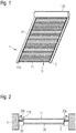
- the sheet 10 is designed in the form of a roller shutter shell 11.
- the roller shutter armor has two side edges 110, which are received in associated guide rails 20.
- the roller shutter 10 is composed of a plurality of fins 15 which extend transversely from one guide rail to the other guide rail.
- the roller shutter shell 11 can be rolled up with a winding device 115, so that the underlying window opening is released.
- the winding device 115 is different from an additionally existing drive device 2, which is adapted to set the fabric, so the roller shutter 11, for deicing in vibration.
- the guide rails 20 may be articulated at the upper end in the region of the winding device 115, for example with a hinge or a leaf spring. At the lower end can attack an elastic element, as described below with reference to FIG. 3 is explained.
- FIG. 2 shows the mounting of the building element 1 in section.
- a window opening is provided in the building, which is bounded on both sides by walls 3.
- a glazing 30 which is held in a frame 35.
- the glazing 30 may be designed with a rotary wing, a tilting wing or fixed glazing.
- the invention does not teach the use of a special window as a solution principle.
- the building element 1 On the outside of the glazing 30, the building element 1 is arranged with the roller shutter 11.
- FIG. 2 shows, the guide rails 20a and 20b, which receive the side edges 110 of the roller shutter 11, mounted to vibrate.
- an elastic member 25 may be arranged, as shown by FIG. 3 is apparent.
- the elastic element 25 generates a restoring force when the distance of the guide rail 20 from the frame 35 changes and the frame 20 is deflected so far from its rest position.
- At least one drive device 2 is provided.
- the drive device 2 may have a piezo drive or an eccentric drive. As a result, the drive device 2 exert a deflecting force on the guide rail 20.
- the excitation frequency of the drive device 2 may be variable. This can be matched to the natural oscillations of the fabric 10 so that it excites a predetermined oscillation pattern or a predetermined harmonic. In some embodiments of the invention Sequentially different vibration frequencies can be traversed.
- the elastic element 25 is in FIG. 3 represented as a coil spring. In other embodiments of the invention, an elastomer element may also be used or the elastic element 25 may include a soft foam.
- the drive device 2 can be activated automatically after detection of the icing or manually by user intervention, so that the surface element 10 is set in vibration.
- the mechanical bond between the ice sheet and the underlying sheet 10 can be solved, so that the ice ultimately falls from the fabric, so that the winding device 115 can be operated safely.
- neither the heat of fusion of the ice must be overcome for removing ice, nor is the use of chemical de-icing agents necessary, which can pose a danger to the environment.
- FIG. 4 shows a second embodiment of the invention.
- FIG. 4 shows the section through a single lamella 15 of a roller shutter shell 11.
- the lamella 15 has two side edges 110a and 110b, which are intended to be received in a guide rail.
- the lamella 15 is made hollow inside, so that a drive device 2 can be accommodated in the interior of the lamella.
- the drive device 2 comprises a piezo drive, which can generate large actuating forces with small geometrical dimensions.
- the surface 151 of the lamella 15 is substantially planar.
- the Activating the drive device 2 leads to a shortening of the lamella 15, so that its surface bulges.
- the baggy surface may, for example, have the profile 150. If the drive device 2 by cyclic deformation stimulates higher harmonic of the blade 15, this can also be deformed so that the surface 150 has a plurality of nodes and bellies. As a result, adhering ice can be removed with greater efficiency in some embodiments of the invention.
- the acoustic impact on the environment can be kept low and at the same time the adhering ice can be removed efficiently.
- the blade 15 provided with the drive device 2 can be combined with conventional blades, so that not all the blades 15 of the roller shutter shell 11 are actively excited to vibrate. Rather, adjacent lamellae without a drive device can also be excited to vibrate by oscillating lamellae with a drive device.
- FIG. 5 shows a second embodiment of a blade 15 of a roller shutter 11. Identical components of the invention are provided with the same reference numerals, so that the invention is limited to the essential differences.
- the blade 15 according to FIG. 5 has a plurality of drive devices 2.
- three drive devices 2a, 2b and 2c are present.
- the number of drive devices may also be larger or smaller and between 1 and about 15.
- the drive devices 2a act approximately parallel to Surface normal of the sheet 10.
- the effect of the drive devices is approximately orthogonal to that according to FIG. 4 2.
- Each of the drive devices 2a, 2b and 2c generates a force which acts approximately orthogonally on the surface 151 of the lamella 15.
- the surface 151 partially arched at the location of the drive device 2 to the outside or inward, so that upon elastic deformation of the blade 15 mechanical stresses at the interface to the brittle ice arise.
Landscapes
- Engineering & Computer Science (AREA)
- Structural Engineering (AREA)
- Architecture (AREA)
- Civil Engineering (AREA)
- Operating, Guiding And Securing Of Roll- Type Closing Members (AREA)
Description
- Die Erfindung betrifft ein Gebäudeelement mit einem Flächengebilde, welches schwingungsfähig gelagert ist und/oder zu Flächenschwingungen fähig ist. Weiterhin betrifft die Erfindung ein Verfahren zur Enteisung eines Flächengebildes eines Gebäudeelements. Vorrichtungen und Verfahren der eingangsgenannten Art können beispielsweise als Jalousie oder Raffstore im Bauwesen Verwendung finden.
- Aus der Praxis ist bekannt, Fensteröffnungen durch bewegliche Verdunkelungs-, Blendschutz- oder Sonnenschutzvorrichtungen zeitweise zu verschließen. Hierzu können beispielsweise Rollläden, Jalousien oder Raffstores verwendet werden. Bei winterlichen Witterungsbedingungen, welche mit Frost- und Tauwechseln einhergehen, können solche außenliegenden Beschattungs- oder Verdunkelungssysteme vereisen. Dies kann die Funktion dahingehend beeinträchtigen, dass die Sonnenschutzvorrichtung bzw. die Jalousie in der aktuellen Position festgelegt ist. Beispielsweise kann diese nicht mehr aufgerollt werden und muss somit bis zum Einsetzen von Tauwetter vor der Fensteröffnung verbleiben. Alternativ kann auch das aufgerollte Lamellenpaket festfrieren, so dass die Sonnenschutzvorrichtung bzw. die Jalousie nicht mehr geschlossen werden kann. Bei Erdgeschossfenstern kann eine Enteisung möglicherweise noch vom Benutzer von außen durchgeführt werden, beispielweise durch Aufbringen eines Enteisungsmittels. Bei hoch gelegenen Fensteröffnungen besteht jedoch auch diese Möglichkeit nicht.
- Aus der
DE 196 25 215 A1 ist ein Rolltor bekannt, welches ein flexibles Torblatt aufweist, welches auf eine oberhalb einer Gebäudeöffnung drehbar gelagerte Aufwickelwalze aufwickelbar ist und welches seitlich in Führungen geführt ist, welche beheizbar ausgebildet sind. Außerdem ist bei diesem bekannten Rolltor vorgesehen, dass seitliche Dichtungen als Schürzen ausgebildet sind, welche in spitzen Winkel an das Torblatt anliegen. - Die
WO 2006/132478 A1 offenbart einen Antrieb für eine Sonnenschutzvorrichtung mit einem Ultraschallmotor. Dieser kann mit einer Steuerung versehen sein, welche eine manuelle Bedienung und eine automatische Bedienung ermöglicht, welche die Sonnenschutzvorrichtung in Abhängigkeit von Zeit, Tag oder Witterung ansteuert. - Aus der
JP 2014-098256 A - Der Erfindung liegt somit die Aufgabe zugrunde, ein Gebäudeelement und ein Verfahren zur Enteisung eines Flächengebildes anzugeben, welches auch bei ungünstigen Witterungsbedingungen und unabhängig von der Erreichbarkeit der Fensteröffnung zuverlässig funktioniert.
- Die Aufgabe wird erfindungsgemäß durch ein Gebäudeelement gemäß Anspruch 1 und ein Verfahren gemäß Anspruch 9 gelöst.
- Das erfindungsgemäße Gebäudeelement weist ein Flächengebilde auf. Beispielsweise kann das Flächengebilde aus einzelnen Lamellen zusammengesetzt sein, wie bei einem an sich bekannten Rollladenpanzer oder einer an sich bekannten Jalousie oder einem an sich bekannten Raffstore. Alternativ kann das Flächengebilde in einigen Ausführungsformen der Erfindung einen textilen Sonnenschutz umfassen oder daraus bestehen. In der nachfolgenden Beschreibung wird für all diese Elemente der Begriff "Flächengebilde" verwendet. Dies soll Ausführungen einschließen, bei welchen einzelne Lamellen bzw. Elemente beabstandet zueinander angeordnet sind, sodass die Fläche nicht vollständig geschlossen ist.
- Das Flächengebilde kann beispielsweise zum zeitweisen Verschließen bzw. Beschatten einer Fensteröffnung eingesetzt werden und beispielsweise eine Jalousie, ein Raffstore oder ein Rolladen sein. In anderen Ausführungsformen der Erfindung kann das Flächengebilde Teil eines Rolltores sein, welches beispielsweise eine Garage oder eine Werkhalle verschließt. In wiederum anderen Ausführungsformen der Erfindung kann das Flächengebilde Teil einer Verglasung sein.
- Erfindungsgemäß wird nun vorgeschlagen, das Flächengebilde entweder schwingungsfähig zu lagern und/oder so auszubilden, dass es zu Flächenschwingungen fähig ist. Eine schwingungsfähige Lagerung kann dann angenommen werden, wenn die Befestigungsvorrichtungen des Flächengebildes, beispielsweise Führungsschienen, bei Auslenkung aus ihrer Ruhelage eine Rückstellkraft erfahren. Ein Flächengebilde ist zu Flächenschwingungen fähig, wenn dieses bei Verformung in seine Ausgangsform zurückkehrt.
- Erfindungsgemäß wird nun weiterhin vorgeschlagen, das Gebäudeelement mit einer Antriebseinrichtung zu versehen, mit welcher das Flächengebilde in erzwungene Schwingungen versetzbar ist. Durch die Schwingungen des Flächengebildes kann die mechanische Bindung zwischen einer Eisschicht und der darunter liegenden Oberfläche des Flächengebildes gelöst werden. Das Eis kann somit durch Schwingungen vom Flächengebilde gelöst werden, sodass das Flächengebilde danach wieder frei beweglich ist und nach Wünschen des Benutzers entweder aus- oder eingerollt oder verstellt werden kann.
- In einigen Ausführungsformen der Erfindung kann die Antriebseinrichtung ausgewählt sein aus zumindest einem Piezoaktor und/oder einem Exzenterantrieb und/oder einem elektromagnetischen Antrieb. Ein Exzenterantrieb kann beispielsweise mit elektrischen oder mechanischen Antriebsmitteln versehen sein, um eine periodische Kraft auf das Flächengebilde oder dessen Befestigung auszuüben. Ein mechanischer Excenterantrieb, beispielsweise über eine Kurbel, kann vom Benutzer ohne elektrische Hilfsenergie benutzt werden und eignet sich damit auch für den Einsatz an abgelegenen Orten oder den Einsatz in Fahrzeugen mit begrenzten Energieressourcen. Ein Piezoantrieb kann hohe Frequenzen und hohe Stellkräfte bei kompakter Bauform bereitstellen. Ein elektromagnetischer Antrieb kann eine mit einem Wechselstrom beaufschlagte Spule enthalten, welche eine zyklische Kraft auf einen Kern ausübt, ähnlich wie ein Lautsprecherantrieb.
- In einigen Ausführungsformen der Erfindung kann die Antriebseinrichtung von einer elektronischen Steuereinrichtung angesteuert werden. Die Steuereinrichtung kann die Antriebseinrichtung entweder witterungsgeführt aktivieren, wenn eine Vereisung des Flächenelements zur Erwarten ist. In anderen Ausführungsformen der Erfindung kann die Steuereinrichtung die Antriebseinrichtung dann aktivieren, wenn eine Vereisung erkannt wurde, beispielsweise durch Ansprechen einer Überlastsicherung eines Rollladenantriebs oder in Abhängigkeit der Messwerte eines Vereisungssensors. In wiederum anderen Ausführungsformen der Erfindung kann die Antriebseinrichtung manuell durch einen Benutzereingriff aktiviert werden, wenn der Benutzer eine Vereisung des Flächengebildes festgestellt hat.
- In einigen Ausführungsformen der Erfindung kann das Flächengebilde ausgewählt sein aus einem Rollladen und/oder einem Rolltor und/oder einer Verglasung und/oder einem Membrandach und/oder einer Fahrbahn. Durch das Entfernen einer Vereisung von einer Verglasung kann der freie Ausblick durch das Fenster eines Gebäudes sichergestellt werden. Im Falle von Schaufenstern kann selbstverständlich auch ein ungehinderter Einblick in das Gebäude ermöglicht werden. Das Entfernen von Schnee- und Eisanhaftungen von Membrandächern oder Verglasungen kann die Gebäudebelastung verringern, sodass die Statik des Gebäudes einfacher bemessen werden kann. In gleicher Weise können Flugzeugflügel, Flügel von Windkraftanlagen oder Freileitungen von Eis und Schnee befreit werden.
- In einigen Ausführungsformen der Erfindung kann das Flächengebilde ein Rollladen oder ein Rolltor umfassen, welche an zumindest einem Rand in zumindest einer Führungsschiene oder durch Führungsrollen geführt sind, welche mittels eines elastischen Elements am Gebäude befestigt ist. Die Antriebseinrichtung kann in diesem Fall an der Führungsschiene angreifen und durch zyklische Bewegung der Führungsschiene das Flächengebilde in Schwingung versetzen. Zwei gegenüberliegende Führungsschienen können dabei gleichphasig angesteuert werden, um die Amplitude in der Mitte des Flächengebildes zu maximieren. In anderen Ausführungsformen der Erfindung können zwei Führungsschienen gegenphasig angeregt werden, sodass sich das Flächenelement in sich verwindet und so das relativ spröde Eis die Haftung zur Oberfläche des Flächengebildes verliert.
- In einigen Ausführungsformen der Erfindung kann das elastische Element ein Elastomer enthalten oder daraus bestehen. Dies erlaubt eine einfache Montage, beispielsweise mittels eines zylindrischen Elastomerelements, welches zentral auf der Zylinderachse eine Bohrung aufweist, durch welche eine Befestigungsschraube der Führungsschiene am Gebäude bzw. am Fensterrahmen geführt ist. Solche Elastomerelemente sind bekannt, um schwingungsfähige Systeme von anderen Baugruppen zu entkoppeln. Darüber hinaus sind diese Elastomerelemente einfach herstellbar, beispielsweise durch Strangpressen, Vulkanisieren und Ablängen eines Elastomers.
- In einigen Ausführungsformen der Erfindung kann das elastische Element eine Schraubenfeder oder eine Blattfeder enthalten oder daraus bestehen. Auch eine Schraubenfeder kann so ausgebildet sein, dass dies eine Befestigungsschraube der Führungsschiene des Flächengebildes umgibt. Somit kann auch in diesem Fall mittels einer einzigen Schraubverbindung sowohl das elastische Element als auch der Rahmen am Gebäude befestigt werden. Eine Blattfeder kann Teil der Aufhängung bzw. Befestigung des Flächengebildes sein.
- In einigen Ausführungsformen der Erfindung kann die Führungsschiene mit einem Ende gelenkig am Fensterrahmen verbunden sein, wobei das gegenüberliegende Ende der Führungsschiene mittels eines elastischen Elements am Gebäude befestigt ist. Dadurch ist das Gebäudeelement zum einen sicher an der Fassade befestigt und lässt sich durch ein zugeordnetes Antriebselement einfach in Schwingungen versetzen.
- In einigen Ausführungsformen der Erfindung kann das Flächengebilde zumindest Abschnittsweise hohl sein, wobei sich die Antriebseinrichtung innerhalb des Flächengebildes befindet. Hierdurch können Flächenschwingungen des Flächengebildes besonders effizient angeregt werden. Diese führen durch eine temporäre Verformung der Oberfläche des Flächengebildes zum Auftreten von mechanischen Spannungen an der Grenzfläche zwischen Eis und Flächengebilde, sodass die mechanische Bindung zwischen einer Eisschicht und dem darunterliegenden Flächengebilde gelöst wird.
- In einigen Ausführungsformen der Erfindung kann das Flächengebilde einen Rollladen oder ein Rolltor umfassen, welche aus einer Mehrzahl einzelner Lamellen zusammengesetzt sind, deren Profil zumindest teilweise abschnittsweise hohl ist, wobei innerhalb der Lamelle zumindest eine Antriebseinrichtung angeordnet ist. Beispielsweise können Streckschwingungen entlang der Längsausdehnung der Lamellen induziert werden, welche zu einer periodischen Wölbung der Lamelle führen, sodass in der oben beschriebenen Weise anhaftendes Eis entfernt werden kann.
- In einigen Ausführungsformen der Erfindung kann die Antriebseinrichtung dazu eingerichtet sein, höhere Harmonische des Flächengebildes anzuregen. Hierdurch entstehen bei der Flächenschwingung mehrere Knoten und Bäuche, sodass das anhaftende Eis an mehreren Stellen die Bindung zur Unterlage verliert und großflächig abgelöst wird. Darüber hinaus können die Frequenzen der Oberwellen oberhalb der Hörschwelle liegen, sodass eine akustische Beeinträchtigung der Umwelt beim Entfernen des Eises unterbleiben kann oder verringert wird.
- In einigen Ausführungsformen der Erfindung kann die Antriebseinrichtung dazu eingerichtet sein, Schwingungen mit einer Frequenz von etwa 15000 Hz bis etwa 1000000 Hz auszuführen. In einigen Ausführungsformen der Erfindung kann die Antriebseinrichtung dazu eingerichtet sein, Schwingungen mit einer Frequenz von etwa 25000 Hz bis etwa 100000 Hz auszuführen. In einigen Ausführungsformen der Erfindung kann die Antriebseinrichtung dazu eingerichtet sein, Schwingungen mit einer Frequenz von etwa 30000 Hz bis etwa 80000 Hz auszuführen. In einigen Ausführungsformen der Erfindung kann die Antriebseinrichtung dazu eingerichtet sein, Schwingungen mit einer Frequenz von etwa 1 Hz bis etwa 30 Hz auszuführen. In einigen Ausführungsformen der Erfindung kann die Antriebseinrichtung dazu eingerichtet sein, Schwingungen mit einer Frequenz von etwa 10 Hz bis etwa 25 Hz auszuführen.
- In gleicher Weise, wie oben für eine Eisschicht auf einem Flächengebilde ausgeführt, kann auch Schmutz oder flüssiges Wasser von einem Flächengebilde durch Vibration bzw. Schwingungsanregung entfernt werden. Dies ist insbesondere hilfreich, um Wasser von Glaselementen zu entfernen, sodass der Ausblick aus dem Gebäude ungehindert möglich ist.
- Nachfolgend soll die Erfindung anhand von Figuren ohne Beschränkung des allgemeinen Erfindungsgedankens näher erläutert werden. Dabei zeigt
-
Figur 1 eine erste Ausführungsform der Erfindung in der Ansicht. -
Figur 2 zeigt die Ausführungsform gemäßFigur 1 im Schnitt. -
Figur 3 zeigt ein Detail der Befestigung gemäß der ersten Ausführungsform. -
Figur 4 zeigt den Schnitt durch eine Lamelle eines Flächengebildes gemäß einer zweiten Ausführungsform der Erfindung. -
Figur 5 zeigt den Schnitt durch eine Lamelle eines Flächengebildes gemäß einer dritten Ausführungsform der Erfindung. - Anhand der
Figuren 1, 2 und3 wird eine erste Ausführungsform der Erfindung beschrieben. WieFigur 1 zeigt, ist das Flächengebilde 10 in Form eines Rollladenpanzers 11 ausgeführt. Der Rollladenpanzer weist zwei Seitenkanten 110 auf, welche in zugeordneten Führungsschienen 20 aufgenommen sind. Der Rollladenpanzer 10 ist aus mehreren Lamellen 15 zusammengesetzt, welche quer von einer Führungsschiene zur anderen Führungsschiene verlaufen. - Der Rollladenpanzer 11 kann mit einer Wickelvorrichtung 115 aufgerollt werden, sodass die dahinterliegende Fensteröffnung freigegeben wird. Die Wickelvorrichtung 115 ist von einer zusätzlich vorhandenen Antriebseinrichtung 2 verschieden, welche dazu eingerichtet ist, das Flächengebilde, also den Rolladenpanzer 11, zur Enteisung in Schwingungen zu versetzen.
- Die Führungsschienen 20 können am oberen Ende im Bereich der Wickelvorrichtung 115 gelenkig gelagert sein, beispielsweise mit einem Scharnier oder einer Blattfeder. Am unteren Ende kann ein elastisches Element angreifen, wie nachfolgend anhand der
Figur 3 erläutert wird. -
Figur 2 zeigt die Montage des Gebäudeelements 1 im Schnitt. Hierzu ist im Gebäude eine Fensteröffnung vorgesehen, welche beidseitig von Mauern 3 begrenzt ist. In der Fensteröffnung befindet sich eine Verglasung 30, welche in einem Rahmen 35 gehalten ist. Die Verglasung 30 kann mit einem Drehflügel, einem Kippflügel oder als Festverglasung ausgeführt sein. Die Erfindung lehrt nicht die Verwendung eines speziellen Fensters als Lösungsprinzip. - Auf der Außenseite der Verglasung 30 ist das Gebäudeelement 1 mit dem Rollladenpanzer 11 angeordnet.
- Wie
Figur 2 zeigt, sind die Führungsschienen 20a und 20b, welche die Seitenkanten 110 des Rollladenpanzers 11 aufnehmen, schwingungsfähig gelagert. Hierzu kann zwischen dem Fensterrahmen 35 und der Führungsschiene 20 ein elastisches Element 25 angeordnet sein, wie anhand vonFigur 3 ersichtlich ist. Das elastische Element 25 erzeugt eine Rückstellkraft, wenn sich der Abstand der Führungsschiene 20 vom Rahmen 35 ändert und der Rahmen 20 insoweit aus seiner Ruhelage ausgelenkt wird. - Zum Anregen einer Schwingung des Flächengebildes 10 ist zumindest eine Antriebseinrichtung 2 vorgesehen. Die Antriebseinrichtung 2 kann einen Piezoantrieb oder einen Exzenterantrieb aufweisen. Hierdurch kann die Antriebseinrichtung 2 eine auslenkende Kraft auf die Führungsschiene 20 ausüben. Die Anregungsfrequenz der Antriebsvorrichtung 2 kann variabel sein. Diese kann so auf die Eigenschwingungen des Flächengebildes 10 abgestimmt sein, dass diese ein vorgebbaren Schwingungsbild bzw. eine vorgebbare Oberschwingung anregt. In einigen Ausführungsformen der Erfindung können sequentiell unterschiedliche Schwingungsfrequenzen durchlaufen werden.
- Das elastische Element 25 ist in
Figur 3 als Schraubenfeder dargestellt. In anderen Ausführungsformen der Erfindung kann auch ein Elastomerelement verwendet werden oder das elastische Element 25 kann einen Weichschaum enthalten. - Sofern das Flächengebilde 10 auf seiner Außenseite bei ungünstiger Witterung vereist, kann dieses nicht mehr in der Wickelvorrichtung 115 aufgerollt werden. In diesem Fall kann automatisiert nach Erkennen der Vereisung oder manuell durch Benutzereingriff die Antriebsvorrichtung 2 aktiviert werden, sodass das Flächenelement 10 in Schwingung versetzt wird. Hierdurch kann die mechanische Bindung zwischen der Eisschicht und dem darunterliegenden Flächengebilde 10 gelöst werden, sodass das Eis letztlich vom Flächengebilde herunterfällt, sodass die Wickelvorrichtung 115 gefahrlos bedient werden kann. Dabei muss vorteilhaft zur Eisentfernung weder die Schmelzwärme des Eises überwunden werden, noch ist der Einsatz von chemischen Taumitteln notwendig, welche eine Gefahr für die Umwelt darstellen können.
-
Figur 4 zeigt eine zweite Ausführungsform der Erfindung.Figur 4 zeigt den Schnitt durch eine einzelne Lamelle 15 eines Rollladenpanzers 11. Die Lamelle 15 weist zwei Seitenkanten 110a und 110b auf, welche zur Aufnahme in einer Führungsschiene bestimmt sind. - Die Lamelle 15 ist im Inneren hohl ausgeführt, sodass eine Antriebsvorrichtung 2 im Inneren der Lamelle aufgenommen werden kann. Bevorzugt umfasst die Antriebsvorrichtung 2 einen Piezoantrieb, welcher große Stellkräfte bei geringen geometrischen Abmessungen erzeugen kann.
- Sofern die Antriebsvorrichtung 2 nicht aktiviert wird, ist die Oberfläche 151 der Lamelle 15 im Wesentlichen eben. Das Aktivieren der Antriebsvorrichtung 2 führt zu einer Verkürzung der Lamelle 15, sodass deren Oberfläche ausbeult. Die ausgebeulte Oberfläche kann beispielsweise den Verlauf 150 aufweisen. Sofern die Antriebsvorrichtung 2 durch zyklische Verformung höhere harmonische der Lamelle 15 anregt, kann diese auch so verformt werden, dass die Oberfläche 150 mehrere Knoten und Bäuche aufweist. Hierdurch kann anhaftendes Eis in einigen Ausführungsformen der Erfindung mit größerer Effizienz entfernt werden.
- Durch die unmittelbare Schwingungsanregung der Lamelle 15 kann die akustische Beeinträchtigung der Umwelt gering gehalten werden und gleichzeitig das anhaftende Eis effizient entfernt werden.
- In einigen Ausführungsformen der Erfindung kann die mit der Antriebsvorrichtung 2 versehene Lamelle 15 mit konventionellen Lamellen kombiniert werden, sodass nicht sämtliche Lamellen 15 des Rollladenpanzers 11 aktiv zu Schwingungen angeregt werden. Vielmehr können benachbarte Lamellen ohne Antriebsvorrichtung durch schwingende Lamellen mit Antriebsvorrichtung ebenfalls zu Schwingungen angeregt werden.
-
Figur 5 zeigt eine zweite Ausführungsform einer Lamelle 15 eines Rollladenpanzers 11. Gleiche Bestandteile der Erfindung sind mit gleichen Bezugszeichen versehen, sodass sich die Erfindung auf die wesentlichen Unterschiede beschränkt. - Die Lamelle 15 gemäß
Figur 5 weist eine Mehrzahl von Antriebsvorrichtungen 2 auf. Im dargestellten Ausführungsbeispiel sind drei Antriebsvorrichtungen 2a, 2b und 2c vorhanden. In anderen Ausführungsformen der Erfindung kann die Anzahl der Antriebsvorrichtungen auch größer oder geringer sein und zwischen 1 und etwa 15 betragen. Die Antriebsvorrichtungen 2a wirken in etwa parallel zur Flächennormale des Flächengebildes 10. Somit ist die Wirkung der Antriebsvorrichtungen in etwa orthogonal zu der gemäßFigur 4 verwendeten Antriebsvorrichtung 2. Jede der Antriebsvorrichtungen 2a, 2b und 2c erzeugt eine Kraft, welche in etwa orthogonal auf die Fläche 151 der Lamelle 15 einwirkt. Hierdurch wird die Fläche 151 partiell am Ort der Antriebsvorrichtung 2 nach außen oder nach innen gewölbt, sodass bei elastischer Verformung der Lamelle 15 mechanische Spannungen an der Grenzfläche zum spröden Eis entstehen. Hierdurch kann die Bindung zwischen der Eisschicht und dem darunterliegenden Flächengebilde 10 gelöst werden. Selbstverständlich ist die Erfindung nicht auf die in den Figuren dargestellte Ausführungsformen beschränkt. Die vorstehende Beschreibung ist daher nicht als beschränkend, sondern als erläuternd anzusehen. Die nachfolgenden Ansprüche sind so zu verstehen, dass ein genanntes Merkmal in zumindest einer Ausführungsform der Erfindung vorhanden ist. Dies schließt die Anwesenheit weiterer Merkmale nicht aus. Sofern die Ansprüche und die vorstehende Beschreibung "erste" und "zweite" Ausführungsformen definieren, so dient diese Bezeichnung der Unterscheidung zweier gleichartiger Ausführungsformen, ohne eine Rangfolge festzulegen. Merkmale aus unterschiedlichen Ausführungsformen der Erfindung können jederzeit kombiniert werden, um so weitere Ausführungsformen der Erfindung zu erhalten.
Claims (12)
- Gebäudeelement (1) mit einem Flächengebilde (10), welches mittels einer Wickelvorrichtung (115) aufrollbar ist,
dadurch gekennzeichnet, dass
das Gebäudeelement weiterhin eine Antriebseinrichtung (2) aufweist, mit welcher das Flächengebilde (10) in Schwingungen versetzbar ist. - Gebäudeelement nach Anspruch 1, dadurch gekennzeichnet, dass die Antriebseinrichtung (2) ausgewählt ist aus zumindest einem Piezoaktor und/oder einem Excenterantrieb und/oder einem elektromagnetischen Antrieb.
- Gebäudeelement nach Anspruch 1 oder 2, dadurch gekennzeichnet, dass das Flächengebilde (10) ausgewählt ist aus einem Rolladen (11) und/oder ein Rolltor und/oder einem Raffstore und/oder einer Jalousie.
- Gebäudeelement nach einem der Ansprüche 1 bis 3, dadurch gekennzeichnet, dass das Flächengebilde (10) elastisch gelagert ist und/oder zu Flächenschwingungen fähig ist.
- Gebäudeelement nach einem der Ansprüche 1 bis 4, dadruch gekennzeichnet, dass das Flächengebilde (10) an zumindest einem Rand (110) in zumindest einer Führungsschiene (20) geführt ist, welche mittels eines elastischen Elementes (25) am Gebäude befestigt ist.
- Gebäudeelement nach Anspruch 5, dadurch gekennzeichnet, dass das elastische Element (25) ein Elastomer enthält oder daraus besteht.
- Gebäudeelement nach einem der Ansprüche 1 bis 6, dadurch gekennzeichnet, dass das Flächengebilde (10) einen Rolladen (11) oder ein Rolltor oder einen Raffstore umfasst, welcher aus einer Mehrzahl einzelner Lamellen (15) zusammengesetzt ist, deren Profil zumindest teilweise abschnittsweise hohl ist, wobei in zumindest einer Lamelle zumindest eine Antriebseinrichtung (2) angeordnet ist.
- Gebäudeelement nach einem der Ansprüche 1 bis 7, dadurch gekennzeichnet, dass die Antriebseinrichtung (2) dazu eingerichtet ist, höhere Harmonische des Flächengebildes anzuregen.
- Verfahren zur Enteisung eines Flächengebildes (10) eines Gebäudeelementes (1), bei welchem das Flächengebilde (10) mit einer Wickelvorrichtung (115) aufwickelbar und schwingungsfähig gelagert ist und/oder zu Flächenschwingungen fähig ist, dadurch gekennzeichnet, dass das Flächengebilde (10) mit einer Antriebseinrichtung (2) in Schwingungen versetzt wird, so dass die mechanische Bindung zwischen einer Eisschicht und dem darunterliegenden Flächengebilde (10) gelöst wird.
- Verfahren nach Anspruch 9, dadurch gekennzeichnet, dass die Frequenz der Antriebseinrichtung (2) so gewählt ist, dass höhere Harmonische des Flächengebildes angeregt werden.
- Verfahren nach einem der Ansprüche 9 oder 10, dadurch gekennzeichnet, dass das Flächengebilde ausgewählt ist aus einem Rolladen und/oder einem Raffstor und/oder einem Rolltor.
- Verfahren nach einem der Ansprüche 9 bis 11, dadurch gekennzeichnet, dass das Flächengebilde (10) einen Rolladen umfasst, welcher an zumindest einem Rand (110) in zumindest einer Führungsschiene (20) geführt ist, welche mittels eines elastischen Elementes (25) am Gebäude befestigt ist, wobei die Führungsschiene (20) mittels der Antriebsmittel (2) in Schwingung versetzt wird.
Priority Applications (1)
| Application Number | Priority Date | Filing Date | Title |
|---|---|---|---|
| PL16745766T PL3332079T3 (pl) | 2015-08-03 | 2016-08-03 | Element budynku i sposób odladzania płaskiej struktury |
Applications Claiming Priority (2)
| Application Number | Priority Date | Filing Date | Title |
|---|---|---|---|
| DE102015214753.3A DE102015214753A1 (de) | 2015-08-03 | 2015-08-03 | Gebäudeelement und Verfahren zur Enteisung eines Flächengebildes |
| PCT/EP2016/068529 WO2017021443A1 (de) | 2015-08-03 | 2016-08-03 | Gebäudeelement und verfahren zur enteisung eines flächengebildes |
Publications (2)
| Publication Number | Publication Date |
|---|---|
| EP3332079A1 EP3332079A1 (de) | 2018-06-13 |
| EP3332079B1 true EP3332079B1 (de) | 2019-07-10 |
Family
ID=56561377
Family Applications (1)
| Application Number | Title | Priority Date | Filing Date |
|---|---|---|---|
| EP16745766.2A Active EP3332079B1 (de) | 2015-08-03 | 2016-08-03 | Gebäudeelement und verfahren zur enteisung eines flächengebildes |
Country Status (4)
| Country | Link |
|---|---|
| EP (1) | EP3332079B1 (de) |
| DE (1) | DE102015214753A1 (de) |
| PL (1) | PL3332079T3 (de) |
| WO (1) | WO2017021443A1 (de) |
Families Citing this family (2)
| Publication number | Priority date | Publication date | Assignee | Title |
|---|---|---|---|---|
| DE102017203720B4 (de) * | 2017-03-07 | 2024-10-02 | Bayerische Motoren Werke Aktiengesellschaft | Enteisungsvorrichtung und Verfahren zum Enteisen eines Personenkraftwagens |
| DE102021133162A1 (de) | 2021-12-15 | 2022-12-15 | Audi Aktiengesellschaft | Vorrichtung |
Family Cites Families (4)
| Publication number | Priority date | Publication date | Assignee | Title |
|---|---|---|---|---|
| DE19625215C2 (de) * | 1996-06-25 | 2001-05-03 | Cardo Door Continental B V | Schnellaufrolltor für Tiefkühlhäuser |
| DE19826168A1 (de) * | 1998-06-13 | 1999-08-26 | Daimler Chrysler Ag | Verfahren und Vorrichtung zum Reinigen von in einer Halterung angeordneten Gläsern und anderen außenliegenden Bauteilen |
| WO2006132478A1 (en) * | 2005-06-04 | 2006-12-14 | Surnex Co. Ltd. | Screen driver apparatus and control apparatus for motor applied thereof |
| JP5676547B2 (ja) * | 2012-11-13 | 2015-02-25 | 小松電機産業株式会社 | シートシャッタの除霜方法 |
-
2015
- 2015-08-03 DE DE102015214753.3A patent/DE102015214753A1/de not_active Ceased
-
2016
- 2016-08-03 WO PCT/EP2016/068529 patent/WO2017021443A1/de not_active Ceased
- 2016-08-03 PL PL16745766T patent/PL3332079T3/pl unknown
- 2016-08-03 EP EP16745766.2A patent/EP3332079B1/de active Active
Non-Patent Citations (1)
| Title |
|---|
| None * |
Also Published As
| Publication number | Publication date |
|---|---|
| PL3332079T3 (pl) | 2020-03-31 |
| DE102015214753A1 (de) | 2017-02-09 |
| WO2017021443A1 (de) | 2017-02-09 |
| EP3332079A1 (de) | 2018-06-13 |
Similar Documents
| Publication | Publication Date | Title |
|---|---|---|
| EP2039871B1 (de) | Rolladen und Glied dafür | |
| EP1525368B1 (de) | Rollovorrichtung | |
| DE69807438T2 (de) | Universelle befestigungs- und parallelführungsvorrichtung für eine fensterabschirmung | |
| EP2060421A1 (de) | Rolloanordnung mit verminderter Reibung im Antrieb | |
| EP3332079B1 (de) | Gebäudeelement und verfahren zur enteisung eines flächengebildes | |
| DE19542040A1 (de) | Verfahren zur Herstellung von Verglasungen sowie Verglasung, insbesondere Sicherheitsverglasung | |
| DE69903758T2 (de) | Fensterrollo mit einem biegsamen Gehäuse | |
| DE202009013560U1 (de) | Gebäudeöffnungsverschattungsvorrichtung und Führungsschienenmodul dafür | |
| DE102020101393A1 (de) | Isolationsvorrichtung zum Einbau in Fensteröffnungen von Gebäuden | |
| EP3091167B1 (de) | Befestigungselement für die befestigung eines fensterrahmens an einer gebäudedecke eines bauwerks, zugehöriges bauwerk und verfahren zum befestigen eines fensterrahmens an einer gebäudedecke | |
| DE202011106458U1 (de) | Rollo in kompakter Bauform | |
| DE102016125677A1 (de) | Lamellenrolltor | |
| DE29914406U1 (de) | Rolovorrichtung für Fliegengitter, Sonnenschutz und Dekorationsfolien, vorgesehen für Fenster mit vorhandenen Rolladen/Jalousien | |
| DE102019209537A1 (de) | Rollladen | |
| EP1873346A2 (de) | Vorrichtung zum Öffnen und Schließen einer Gebäudeöffnung | |
| EP2857241A1 (de) | Sonnenschutzrollo aus flexiblen Material für Fahrzeugdach | |
| DE102006059637A1 (de) | Senkrechtbeschattung | |
| DE202005002160U1 (de) | Rolladen-Vorrichtung | |
| DE3918872A1 (de) | Rolladenkasten | |
| DE202016105975U1 (de) | Beschattungsvorrichtung | |
| DE102020113874A1 (de) | Isolationsvorrichtung | |
| DE8633840U1 (de) | Vorgefertigte Fenster- und Rolladenvorrichtung für Häuser u. dgl. | |
| EP4617463A1 (de) | Dichtelement, bauelement und verfahren zur montage eines bauelementes in einen baukörper | |
| DE102022105035A1 (de) | Wandhalter zum Befestigen eines Führungselements einer Sonnenschutzanlage sowie Sonnenschutzanlage | |
| DE202022106057U1 (de) | Lamelle für einen Rollladen, Rollladen umfassend mindestens eine Lamelle, Rahmen mit Rollladen und Zarge mit Rollladen |
Legal Events
| Date | Code | Title | Description |
|---|---|---|---|
| STAA | Information on the status of an ep patent application or granted ep patent |
Free format text: STATUS: THE INTERNATIONAL PUBLICATION HAS BEEN MADE |
|
| PUAI | Public reference made under article 153(3) epc to a published international application that has entered the european phase |
Free format text: ORIGINAL CODE: 0009012 |
|
| STAA | Information on the status of an ep patent application or granted ep patent |
Free format text: STATUS: REQUEST FOR EXAMINATION WAS MADE |
|
| 17P | Request for examination filed |
Effective date: 20180302 |
|
| AK | Designated contracting states |
Kind code of ref document: A1 Designated state(s): AL AT BE BG CH CY CZ DE DK EE ES FI FR GB GR HR HU IE IS IT LI LT LU LV MC MK MT NL NO PL PT RO RS SE SI SK SM TR |
|
| AX | Request for extension of the european patent |
Extension state: BA ME |
|
| DAV | Request for validation of the european patent (deleted) | ||
| DAX | Request for extension of the european patent (deleted) | ||
| GRAP | Despatch of communication of intention to grant a patent |
Free format text: ORIGINAL CODE: EPIDOSNIGR1 |
|
| STAA | Information on the status of an ep patent application or granted ep patent |
Free format text: STATUS: GRANT OF PATENT IS INTENDED |
|
| INTG | Intention to grant announced |
Effective date: 20190226 |
|
| GRAS | Grant fee paid |
Free format text: ORIGINAL CODE: EPIDOSNIGR3 |
|
| GRAA | (expected) grant |
Free format text: ORIGINAL CODE: 0009210 |
|
| STAA | Information on the status of an ep patent application or granted ep patent |
Free format text: STATUS: THE PATENT HAS BEEN GRANTED |
|
| AK | Designated contracting states |
Kind code of ref document: B1 Designated state(s): AL AT BE BG CH CY CZ DE DK EE ES FI FR GB GR HR HU IE IS IT LI LT LU LV MC MK MT NL NO PL PT RO RS SE SI SK SM TR |
|
| REG | Reference to a national code |
Ref country code: GB Ref legal event code: FG4D Free format text: NOT ENGLISH |
|
| REG | Reference to a national code |
Ref country code: CH Ref legal event code: EP Ref country code: AT Ref legal event code: REF Ref document number: 1153747 Country of ref document: AT Kind code of ref document: T Effective date: 20190715 |
|
| REG | Reference to a national code |
Ref country code: DE Ref legal event code: R096 Ref document number: 502016005507 Country of ref document: DE |
|
| REG | Reference to a national code |
Ref country code: IE Ref legal event code: FG4D Free format text: LANGUAGE OF EP DOCUMENT: GERMAN |
|
| REG | Reference to a national code |
Ref country code: NL Ref legal event code: MP Effective date: 20190710 |
|
| REG | Reference to a national code |
Ref country code: LT Ref legal event code: MG4D |
|
| PG25 | Lapsed in a contracting state [announced via postgrant information from national office to epo] |
Ref country code: FI Free format text: LAPSE BECAUSE OF FAILURE TO SUBMIT A TRANSLATION OF THE DESCRIPTION OR TO PAY THE FEE WITHIN THE PRESCRIBED TIME-LIMIT Effective date: 20190710 Ref country code: PT Free format text: LAPSE BECAUSE OF FAILURE TO SUBMIT A TRANSLATION OF THE DESCRIPTION OR TO PAY THE FEE WITHIN THE PRESCRIBED TIME-LIMIT Effective date: 20191111 Ref country code: LT Free format text: LAPSE BECAUSE OF FAILURE TO SUBMIT A TRANSLATION OF THE DESCRIPTION OR TO PAY THE FEE WITHIN THE PRESCRIBED TIME-LIMIT Effective date: 20190710 Ref country code: NL Free format text: LAPSE BECAUSE OF FAILURE TO SUBMIT A TRANSLATION OF THE DESCRIPTION OR TO PAY THE FEE WITHIN THE PRESCRIBED TIME-LIMIT Effective date: 20190710 Ref country code: BG Free format text: LAPSE BECAUSE OF FAILURE TO SUBMIT A TRANSLATION OF THE DESCRIPTION OR TO PAY THE FEE WITHIN THE PRESCRIBED TIME-LIMIT Effective date: 20191010 Ref country code: NO Free format text: LAPSE BECAUSE OF FAILURE TO SUBMIT A TRANSLATION OF THE DESCRIPTION OR TO PAY THE FEE WITHIN THE PRESCRIBED TIME-LIMIT Effective date: 20191010 Ref country code: SE Free format text: LAPSE BECAUSE OF FAILURE TO SUBMIT A TRANSLATION OF THE DESCRIPTION OR TO PAY THE FEE WITHIN THE PRESCRIBED TIME-LIMIT Effective date: 20190710 Ref country code: HR Free format text: LAPSE BECAUSE OF FAILURE TO SUBMIT A TRANSLATION OF THE DESCRIPTION OR TO PAY THE FEE WITHIN THE PRESCRIBED TIME-LIMIT Effective date: 20190710 |
|
| PG25 | Lapsed in a contracting state [announced via postgrant information from national office to epo] |
Ref country code: IS Free format text: LAPSE BECAUSE OF FAILURE TO SUBMIT A TRANSLATION OF THE DESCRIPTION OR TO PAY THE FEE WITHIN THE PRESCRIBED TIME-LIMIT Effective date: 20191110 Ref country code: LV Free format text: LAPSE BECAUSE OF FAILURE TO SUBMIT A TRANSLATION OF THE DESCRIPTION OR TO PAY THE FEE WITHIN THE PRESCRIBED TIME-LIMIT Effective date: 20190710 Ref country code: GR Free format text: LAPSE BECAUSE OF FAILURE TO SUBMIT A TRANSLATION OF THE DESCRIPTION OR TO PAY THE FEE WITHIN THE PRESCRIBED TIME-LIMIT Effective date: 20191011 Ref country code: RS Free format text: LAPSE BECAUSE OF FAILURE TO SUBMIT A TRANSLATION OF THE DESCRIPTION OR TO PAY THE FEE WITHIN THE PRESCRIBED TIME-LIMIT Effective date: 20190710 Ref country code: AL Free format text: LAPSE BECAUSE OF FAILURE TO SUBMIT A TRANSLATION OF THE DESCRIPTION OR TO PAY THE FEE WITHIN THE PRESCRIBED TIME-LIMIT Effective date: 20190710 Ref country code: ES Free format text: LAPSE BECAUSE OF FAILURE TO SUBMIT A TRANSLATION OF THE DESCRIPTION OR TO PAY THE FEE WITHIN THE PRESCRIBED TIME-LIMIT Effective date: 20190710 |
|
| PG25 | Lapsed in a contracting state [announced via postgrant information from national office to epo] |
Ref country code: TR Free format text: LAPSE BECAUSE OF FAILURE TO SUBMIT A TRANSLATION OF THE DESCRIPTION OR TO PAY THE FEE WITHIN THE PRESCRIBED TIME-LIMIT Effective date: 20190710 |
|
| PG25 | Lapsed in a contracting state [announced via postgrant information from national office to epo] |
Ref country code: DK Free format text: LAPSE BECAUSE OF FAILURE TO SUBMIT A TRANSLATION OF THE DESCRIPTION OR TO PAY THE FEE WITHIN THE PRESCRIBED TIME-LIMIT Effective date: 20190710 Ref country code: EE Free format text: LAPSE BECAUSE OF FAILURE TO SUBMIT A TRANSLATION OF THE DESCRIPTION OR TO PAY THE FEE WITHIN THE PRESCRIBED TIME-LIMIT Effective date: 20190710 Ref country code: RO Free format text: LAPSE BECAUSE OF FAILURE TO SUBMIT A TRANSLATION OF THE DESCRIPTION OR TO PAY THE FEE WITHIN THE PRESCRIBED TIME-LIMIT Effective date: 20190710 |
|
| PG25 | Lapsed in a contracting state [announced via postgrant information from national office to epo] |
Ref country code: SM Free format text: LAPSE BECAUSE OF FAILURE TO SUBMIT A TRANSLATION OF THE DESCRIPTION OR TO PAY THE FEE WITHIN THE PRESCRIBED TIME-LIMIT Effective date: 20190710 Ref country code: CZ Free format text: LAPSE BECAUSE OF FAILURE TO SUBMIT A TRANSLATION OF THE DESCRIPTION OR TO PAY THE FEE WITHIN THE PRESCRIBED TIME-LIMIT Effective date: 20190710 Ref country code: MC Free format text: LAPSE BECAUSE OF FAILURE TO SUBMIT A TRANSLATION OF THE DESCRIPTION OR TO PAY THE FEE WITHIN THE PRESCRIBED TIME-LIMIT Effective date: 20190710 Ref country code: LU Free format text: LAPSE BECAUSE OF NON-PAYMENT OF DUE FEES Effective date: 20190803 Ref country code: LI Free format text: LAPSE BECAUSE OF NON-PAYMENT OF DUE FEES Effective date: 20190831 Ref country code: SK Free format text: LAPSE BECAUSE OF FAILURE TO SUBMIT A TRANSLATION OF THE DESCRIPTION OR TO PAY THE FEE WITHIN THE PRESCRIBED TIME-LIMIT Effective date: 20190710 Ref country code: CH Free format text: LAPSE BECAUSE OF NON-PAYMENT OF DUE FEES Effective date: 20190831 Ref country code: IS Free format text: LAPSE BECAUSE OF FAILURE TO SUBMIT A TRANSLATION OF THE DESCRIPTION OR TO PAY THE FEE WITHIN THE PRESCRIBED TIME-LIMIT Effective date: 20200224 |
|
| REG | Reference to a national code |
Ref country code: BE Ref legal event code: MM Effective date: 20190831 |
|
| REG | Reference to a national code |
Ref country code: DE Ref legal event code: R097 Ref document number: 502016005507 Country of ref document: DE |
|
| PLBE | No opposition filed within time limit |
Free format text: ORIGINAL CODE: 0009261 |
|
| STAA | Information on the status of an ep patent application or granted ep patent |
Free format text: STATUS: NO OPPOSITION FILED WITHIN TIME LIMIT |
|
| PG2D | Information on lapse in contracting state deleted |
Ref country code: IS |
|
| PG25 | Lapsed in a contracting state [announced via postgrant information from national office to epo] |
Ref country code: IE Free format text: LAPSE BECAUSE OF NON-PAYMENT OF DUE FEES Effective date: 20190803 |
|
| 26N | No opposition filed |
Effective date: 20200603 |
|
| PG25 | Lapsed in a contracting state [announced via postgrant information from national office to epo] |
Ref country code: SI Free format text: LAPSE BECAUSE OF FAILURE TO SUBMIT A TRANSLATION OF THE DESCRIPTION OR TO PAY THE FEE WITHIN THE PRESCRIBED TIME-LIMIT Effective date: 20190710 Ref country code: BE Free format text: LAPSE BECAUSE OF NON-PAYMENT OF DUE FEES Effective date: 20190831 |
|
| PG25 | Lapsed in a contracting state [announced via postgrant information from national office to epo] |
Ref country code: CY Free format text: LAPSE BECAUSE OF FAILURE TO SUBMIT A TRANSLATION OF THE DESCRIPTION OR TO PAY THE FEE WITHIN THE PRESCRIBED TIME-LIMIT Effective date: 20190710 |
|
| PG25 | Lapsed in a contracting state [announced via postgrant information from national office to epo] |
Ref country code: HU Free format text: LAPSE BECAUSE OF FAILURE TO SUBMIT A TRANSLATION OF THE DESCRIPTION OR TO PAY THE FEE WITHIN THE PRESCRIBED TIME-LIMIT; INVALID AB INITIO Effective date: 20160803 Ref country code: MT Free format text: LAPSE BECAUSE OF FAILURE TO SUBMIT A TRANSLATION OF THE DESCRIPTION OR TO PAY THE FEE WITHIN THE PRESCRIBED TIME-LIMIT Effective date: 20190710 |
|
| PG25 | Lapsed in a contracting state [announced via postgrant information from national office to epo] |
Ref country code: MK Free format text: LAPSE BECAUSE OF FAILURE TO SUBMIT A TRANSLATION OF THE DESCRIPTION OR TO PAY THE FEE WITHIN THE PRESCRIBED TIME-LIMIT Effective date: 20190710 |
|
| REG | Reference to a national code |
Ref country code: AT Ref legal event code: MM01 Ref document number: 1153747 Country of ref document: AT Kind code of ref document: T Effective date: 20210803 |
|
| PG25 | Lapsed in a contracting state [announced via postgrant information from national office to epo] |
Ref country code: AT Free format text: LAPSE BECAUSE OF NON-PAYMENT OF DUE FEES Effective date: 20210803 |
|
| P01 | Opt-out of the competence of the unified patent court (upc) registered |
Effective date: 20230524 |
|
| PGFP | Annual fee paid to national office [announced via postgrant information from national office to epo] |
Ref country code: DE Payment date: 20250819 Year of fee payment: 10 |
|
| PGFP | Annual fee paid to national office [announced via postgrant information from national office to epo] |
Ref country code: PL Payment date: 20250718 Year of fee payment: 10 Ref country code: IT Payment date: 20250829 Year of fee payment: 10 |
|
| PGFP | Annual fee paid to national office [announced via postgrant information from national office to epo] |
Ref country code: GB Payment date: 20250818 Year of fee payment: 10 |
|
| PGFP | Annual fee paid to national office [announced via postgrant information from national office to epo] |
Ref country code: FR Payment date: 20250821 Year of fee payment: 10 |