EP3328773B1 - Absorber für schiene eines aufzugssystems - Google Patents
Absorber für schiene eines aufzugssystems Download PDFInfo
- Publication number
- EP3328773B1 EP3328773B1 EP15784453.1A EP15784453A EP3328773B1 EP 3328773 B1 EP3328773 B1 EP 3328773B1 EP 15784453 A EP15784453 A EP 15784453A EP 3328773 B1 EP3328773 B1 EP 3328773B1
- Authority
- EP
- European Patent Office
- Prior art keywords
- absorber
- guide rail
- elevator system
- fluid
- hoistway
- Prior art date
- Legal status (The legal status is an assumption and is not a legal conclusion. Google has not performed a legal analysis and makes no representation as to the accuracy of the status listed.)
- Active
Links
- 239000006096 absorbing agent Substances 0.000 title claims description 63
- 239000012530 fluid Substances 0.000 claims description 31
- 238000000034 method Methods 0.000 claims description 6
- 230000006835 compression Effects 0.000 claims description 3
- 238000007906 compression Methods 0.000 claims description 3
- 230000002452 interceptive effect Effects 0.000 claims description 3
- 230000003319 supportive effect Effects 0.000 claims 3
- 230000000694 effects Effects 0.000 description 4
- 239000000725 suspension Substances 0.000 description 3
- 238000009434 installation Methods 0.000 description 2
- 230000035939 shock Effects 0.000 description 2
- 238000004513 sizing Methods 0.000 description 2
- 238000009435 building construction Methods 0.000 description 1
- 238000010276 construction Methods 0.000 description 1
- 239000003562 lightweight material Substances 0.000 description 1
- 230000000737 periodic effect Effects 0.000 description 1
- 230000001960 triggered effect Effects 0.000 description 1
Images


Classifications
-
- B—PERFORMING OPERATIONS; TRANSPORTING
- B66—HOISTING; LIFTING; HAULING
- B66B—ELEVATORS; ESCALATORS OR MOVING WALKWAYS
- B66B7/00—Other common features of elevators
- B66B7/02—Guideways; Guides
- B66B7/023—Mounting means therefor
- B66B7/025—End supports, i.e. at top or bottom
-
- B—PERFORMING OPERATIONS; TRANSPORTING
- B66—HOISTING; LIFTING; HAULING
- B66B—ELEVATORS; ESCALATORS OR MOVING WALKWAYS
- B66B5/00—Applications of checking, fault-correcting, or safety devices in elevators
- B66B5/28—Buffer-stops for cars, cages, or skips
- B66B5/282—Structure thereof
-
- B—PERFORMING OPERATIONS; TRANSPORTING
- B66—HOISTING; LIFTING; HAULING
- B66B—ELEVATORS; ESCALATORS OR MOVING WALKWAYS
- B66B9/00—Kinds or types of lifts in, or associated with, buildings or other structures
-
- F—MECHANICAL ENGINEERING; LIGHTING; HEATING; WEAPONS; BLASTING
- F16—ENGINEERING ELEMENTS AND UNITS; GENERAL MEASURES FOR PRODUCING AND MAINTAINING EFFECTIVE FUNCTIONING OF MACHINES OR INSTALLATIONS; THERMAL INSULATION IN GENERAL
- F16F—SPRINGS; SHOCK-ABSORBERS; MEANS FOR DAMPING VIBRATION
- F16F9/00—Springs, vibration-dampers, shock-absorbers, or similarly-constructed movement-dampers using a fluid or the equivalent as damping medium
- F16F9/10—Springs, vibration-dampers, shock-absorbers, or similarly-constructed movement-dampers using a fluid or the equivalent as damping medium using liquid only; using a fluid of which the nature is immaterial
- F16F9/14—Devices with one or more members, e.g. pistons, vanes, moving to and fro in chambers and using throttling effect
- F16F9/16—Devices with one or more members, e.g. pistons, vanes, moving to and fro in chambers and using throttling effect involving only straight-line movement of the effective parts
- F16F9/18—Devices with one or more members, e.g. pistons, vanes, moving to and fro in chambers and using throttling effect involving only straight-line movement of the effective parts with a closed cylinder and a piston separating two or more working spaces therein
- F16F9/19—Devices with one or more members, e.g. pistons, vanes, moving to and fro in chambers and using throttling effect involving only straight-line movement of the effective parts with a closed cylinder and a piston separating two or more working spaces therein with a single cylinder and of single-tube type
-
- F—MECHANICAL ENGINEERING; LIGHTING; HEATING; WEAPONS; BLASTING
- F16—ENGINEERING ELEMENTS AND UNITS; GENERAL MEASURES FOR PRODUCING AND MAINTAINING EFFECTIVE FUNCTIONING OF MACHINES OR INSTALLATIONS; THERMAL INSULATION IN GENERAL
- F16F—SPRINGS; SHOCK-ABSORBERS; MEANS FOR DAMPING VIBRATION
- F16F9/00—Springs, vibration-dampers, shock-absorbers, or similarly-constructed movement-dampers using a fluid or the equivalent as damping medium
- F16F9/32—Details
- F16F9/43—Filling or drainage arrangements, e.g. for supply of gas
- F16F9/435—Filling or drainage arrangements, e.g. for supply of gas via opening in cylinder wall
-
- F—MECHANICAL ENGINEERING; LIGHTING; HEATING; WEAPONS; BLASTING
- F16—ENGINEERING ELEMENTS AND UNITS; GENERAL MEASURES FOR PRODUCING AND MAINTAINING EFFECTIVE FUNCTIONING OF MACHINES OR INSTALLATIONS; THERMAL INSULATION IN GENERAL
- F16F—SPRINGS; SHOCK-ABSORBERS; MEANS FOR DAMPING VIBRATION
- F16F2230/00—Purpose; Design features
- F16F2230/0005—Attachment, e.g. to facilitate mounting onto confer adjustability
-
- F—MECHANICAL ENGINEERING; LIGHTING; HEATING; WEAPONS; BLASTING
- F16—ENGINEERING ELEMENTS AND UNITS; GENERAL MEASURES FOR PRODUCING AND MAINTAINING EFFECTIVE FUNCTIONING OF MACHINES OR INSTALLATIONS; THERMAL INSULATION IN GENERAL
- F16F—SPRINGS; SHOCK-ABSORBERS; MEANS FOR DAMPING VIBRATION
- F16F2230/00—Purpose; Design features
- F16F2230/0052—Physically guiding or influencing
- F16F2230/007—Physically guiding or influencing with, or used as an end stop or buffer; Limiting excessive axial separation
-
- F—MECHANICAL ENGINEERING; LIGHTING; HEATING; WEAPONS; BLASTING
- F16—ENGINEERING ELEMENTS AND UNITS; GENERAL MEASURES FOR PRODUCING AND MAINTAINING EFFECTIVE FUNCTIONING OF MACHINES OR INSTALLATIONS; THERMAL INSULATION IN GENERAL
- F16F—SPRINGS; SHOCK-ABSORBERS; MEANS FOR DAMPING VIBRATION
- F16F2230/00—Purpose; Design features
- F16F2230/06—Fluid filling or discharging
Definitions
- the subject matter disclosed herein relates to elevator systems. More particularly, the present disclosure relates to guide rail structures and support for elevator systems.
- guide rails secured in the hoistway are utilized to guide elevator cars and/or counterweights along the hoistway.
- the guide rails are secured to the hoistway wall via guide rail brackets.
- the guide rails are sized to withstand loads from normal elevator system operation, from safety brake actuation at car or counterweight rail, from building settling and the like. In the case of building settling, the guide rails must remain supported by the guide rail brackets while not buckling during the settling.
- Recent changes in elevator systems standards by governing bodies have introduced new requirements requiring that, in elevator systems having a rise of 40 meters or higher, push through forces at all brackets along the guide rail length, as opposed to at a single guide rail bracket, must be taken into account when sizing the guide rails. This would have the effect of increasing the necessary rail size in the elevator systems, which also increases cost. Thus a solution to meet the necessary standard requirements while not significantly increasing rail size or system cost is desired.
- WO 2007/070208 A1 discloses a shock absorber positioned on a pit floor between a car guide rail and the pit floor and/or between the car or counterweight and the pit floor.
- WO 2011/095493 A1 discloses a shock absorber positioned on a pit floor between a guide rail and the pit floor.
- JP 2001 106455 A discloses an absorber according to the preamble of claim 1.
- the invention provides an absorber for an elevator system guide rail as claimed in claim 1.
- a pressure relief valve may periodically release fluid from the housing chamber, thereby reducing a stroke of the absorber piston in the absorber housing.
- a fluid collector may be operably connected to the pressure relief valve to collect the fluid released from the housing chamber via the pressure relief valve.
- the pressure relief valve may release fluid from the housing chamber when a fluid pressure in the housing chamber exceeds a selected threshold.
- the absorber piston may include a recess in the piston upper surface receptive of the guide rail.
- the invention provides an elevator system as claimed in claim 6.
- the one or more guide rails may be at least two guide rails.
- the one or more elevator system components may include an elevator car and/or an elevator system counterweight.
- the invention provides a method of supporting a guide rail of an elevator system as claimed in claim 9.
- fluid may be periodically released from the housing chamber via opening of a pressure relief valve, and a stroke of the absorber piston in the absorber housing is thereby reduced.
- the fluid may be released from the housing chamber via opening of the pressure relief valve when a fluid pressure in the housing chamber exceeds a first threshold.
- the pressure relief valve may be closed when the fluid pressure in the housing chamber falls below a second threshold.
- the first threshold may be substantially equal to the second threshold.
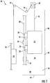
- FIG. 1 Shown in FIG. 1 is a schematic of an exemplary elevator system 10.
- the elevator system 10 includes an elevator car 12 operatively suspended or supported in a hoistway 14 with one or more suspension members 16, such as ropes or belts.
- the one or more suspension members 16 interact with one or more sheaves 18 to be routed around various components of the elevator system 10.
- the one or more sheaves 18 could also be connected to a counterweight 22, which is used to help balance the elevator system 10 and reduce the difference in suspension member 16 tension on both sides of a traction sheave 24 during operation.
- the elevator system 10 further includes one or more car guide rails 28 to guide the elevator car 12 along the hoistway 14.
- the elevator car 12 includes one or more guide shoes or rollers 30 interactive with the car guide rails 28 to guide the elevator car 12.
- the elevator car 12 also may include safeties 32 interactive with the car guide rail 28 to slow and/or stop motion of the elevator car 12 under certain conditions, such as an overspeed condition.
- the elevator system 10 includes one or more counterweight guide rails 34 to guide the counterweight 22 along the hoistway 14.
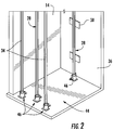
- Car guide rails 28 and counterweight guide rails 34 are installed to hoistway walls 36 using a plurality of guide rail brackets 38, which in some embodiments are located along the hoistway walls 36 at intervals of about 3 meters between guide rail brackets 38.
- the hoistway 14 includes one or more landing floors 40 at which the elevator car 12 stops to allow ingress and/or egress of passengers from the elevator car 12 through elevator car doors (not shown). Below the lowest landing floor 40 of the hoistway 14, the hoistway 14 terminates in a pit 42, including a pit floor 44. After construction of the building and installation of the elevator system 10, some settling or vertical compression of the building typically occurs, especially in buildings having a larger rise. The settling can result in undesired effects on the guide rails of the elevator system 10, such as shifting or buckling due to relative movement of the guide rail brackets 38 and guide rails 28, 34. Further, the settling imparts forces on the guide rails 28, 34 at the guide rail brackets 38 which dictate sizing of the guide rails 28, 34 to withstand such forces.
- each guide rail 28, 34 terminates at an absorber 46 located at the pit floor 44.
- the absorber 46 is configured to absorb the effect of building settling, allowing the guide rails 28, 34 to reposition themselves downwardly relative to the pit floor 44 as the building settles, so that in effect, the guide rails 28, 34 move with the guide rail brackets 38 fixed to the hoistway walls 36. This reduces the relative forces between the guide rails 28, 34 and the guide rail brackets 38.
- the absorber 46 includes an absorber housing 48 with a movable absorber piston 50 located in the absorber housing 48 and movable along a stroke axis 52. As shown in FIG. 3 , the guide rail 28, 34 rests at an upper piston surface 54. In some embodiments, as shown in FIG. 4 , the absorber piston 50 includes a rail recess 56 in which the guide rail 28, 34 may be positioned.
- the absorber housing 48 and absorber piston 50 define a housing chamber 58 in the absorber housing 48.
- the housing chamber 58 is pressurized with a volume of oil or other fluid medium.
- a pressure relief valve 60 and an oil collector tank 62 are fluidly connected to the housing chamber 58.
- the absorber piston 50 is positioned at its maximum position along the stroke axis 52, maximizing the housing chamber 58 volume.
- the guide rail 28, 34 imparts a downward force on the upper piston surface 54, thus increasing a pressure on the fluid in the housing chamber 58.
- the pressure relief valve 60 opens, releasing a volume of fluid from the housing chamber 58 into the oil collector tank 62 and allowing the absorber piston 50 to travel downwardly along the stroke axis 52.
- the pressure relief valve 60 closes, thus stopping travel of the absorber piston 50.
- the first threshold is substantially equal to the second threshold.
- the pressure relief valve 60 has a time delay feature in order to not retract the absorber piston 50 during elevator car 12 or counterweight 22 safety actuation. These events may also increase fluid pressure in the housing chamber 58, but are very short time duration events compared to building settling.
- this operation is repeated over time as the building settles further, in some instances over about the first ten years after building construction.
- fluid pressure 66 in the housing chamber 58 increases until pressure relief valve 60 is opened at point 68, dropping the fluid pressure and retracting the absorber piston 50, shown at 70.
- the absorber piston 50 is retracted further, until it reaches a minimum stroke point 72, at which a safety switch 74 (shown in FIG. 3 , 4 ) is triggered stopping operation of the absorber 46 and will alert to service people to readjust the guide rails 28, 34 and reset the absorbers 46.
- Utilizing the absorbers 46 absorbs forces that would typically be transferred into the guide rails 28, 34 during building settling. This allows for the guide rail 28, 34 configuration to be constrained by other factors such as loads during safety operations, not loads from building settling. Thus, the guide rails 28, 34 can often be formed of more lightweight materials, at a considerable cost savings. Further, the absorbers 46 reduce the risk of guide rail buckling or other deformation to the guide rails 28, 34 and/or guide rail brackets 38.
Claims (13)
- Absorber (46) für eine Führungsschiene (28, 34) eines Aufzugssystems, umfassend:ein Absorbergehäuse (48);einen Absorberkolben (50), der in dem Absorbergehäuse (48) angeordnet ist und zusammen mit dem Absorbergehäuse (48) eine Gehäusekammer (58) definiert, die ein Fluidvolumen enthält, dadurch gekennzeichnet, dass der Absorberkolben (50) eine obere Kolbenfläche (54) einschließt, die konfiguriert ist, um mit einer Führungsschiene (28, 34) eines Aufzugssystems zu interagieren;wobei der Absorber (46) so konfiguriert ist, dass, wenn der Absorber (46) an einer Aufzugschachtgrube (42) angeordnet ist und eine Führungsschiene (28, 34) eines Aufzugssystems stützt, sodass die obere Kolbenfläche (54) mit der Führungsschiene (28, 34) interagiert, eine entsprechende Bewegung der Führungsschiene (28, 34) in Bezug auf den Boden (44) einer Aufzugschachtgrube den Fluiddruck in der Gehäusekammer (58) erhöht, wobei der Absorber (46) konfiguriert ist, um Lasten zu absorbieren, die aufgrund einer vertikalen Verschiebung und/oder Verdichtung eines Schachts (14) des Aufzugssystems auf die Führungsschiene (28, 34) übertragen werden.
- Absorber (46) nach Anspruch 1, ferner umfassend ein Überdruckventil (60), um regelmäßig Fluid aus der Gehäusekammer (58) abzugeben, wodurch ein Hub des Absorberkolbens (50) in dem Absorbergehäuse (48) verringert wird.
- Absorber (46) nach Anspruch 2, ferner umfassend einen Fluidsammler, der mit dem Überdruckventil (60) wirkverbunden ist, um das Fluid zu sammeln, das aus der Gehäusekammer (58) über das Überdruckventil (60) abgegeben wird.
- Absorber (46) nach Anspruch 2 oder 3, wobei das Überdruckventil (60) Fluid aus der Gehäusekammer (58) abgibt, wenn ein Fluiddruck in der Gehäusekammer (58) einen ausgewählten Schwellenwert übersteigt.
- Absorber (46) nach einem der Ansprüche 1-4, wobei der Absorberkolben (50) eine Aussparung (56) in der oberen Kolbenfläche (54) einschließt, welche die Führungsschiene (28, 34) aufnimmt.
- Aufzugssystem (10), umfassend:einen Schacht (14), wobei der Schacht (14) eine Vielzahl von Etagenabsätzen (40) aufweist, wobei jeder Etagenabsatz eine Etagenabsatztür aufweist;eine oder mehrere Führungsschienen (28, 34), die in dem Schacht (14) angeordnet sind, um eine oder mehrere des Aufzugssystemkomponenten entlang des Schachts (14) zu führen; undeinen Absorber (46) nach einem der Ansprüche 1-5, wobei der Absorber (46) an einer Aufzugschachtgrube (42) angeordnet ist und eine Führungsschiene (28, 34) der einen oder mehreren Führungsschienen (28, 34) stützt, wobei der Absorber (46) konfiguriert ist, um Lasten zu absorbieren, die aufgrund einer vertikalen Verschiebung und/oder Verdichtung des Schachts (14) auf die Führungsschiene (28, 34) übertragen werden.
- Aufzugssystem (10) nach Anspruch 6, wobei die eine oder die mehreren Führungsschienen (28, 34) mindestens zwei Führungsschienen entsprechen.
- Aufzugssystem (10) nach Anspruch 6 oder 7, wobei die eine oder die mehreren Aufzugssystemkomponenten eine Aufzugskabine (12) und/oder ein Aufzugssystemgegengewicht (22) einschließen.
- Verfahren zum Stützen einer Führungsschiene (28, 34) eines Aufgzugssystems (10), umfassend:Platzieren eines Absorbers (46) in einem Aufzugsschacht (14) in Wirkverbindung mit einer Führungsschiene (28, 34) eines Aufzugssystems (10), sodass der Absorber (46) an einer Aufzugschachtgrube (42) angeordnet ist und die Führungsschiene (28, 34) stützt, wobei der Absorber (46) ein Absorbergehäuse (48) einschließt, wobei sich ein Absorberkolben (50) in dem Absorbergehäuse (48) befindet, definierend eine Gehäusekammer (58), die ein Fluidvolumen enthält; undÜbertragen von vertikal wirkenden Lasten von der Führungsschiene (28, 34) auf den Absorber (46) über den Absorberkolben (50), wodurch ein Fluiddruck in der Gehäusekammer (58) erhöht wird.
- Verfahren nach Anspruch 9, ferner umfassend:regelmäßiges Abgeben von Fluid aus der Gehäusekammer (58) über das Öffnen eines Überdruckventils (60); undwodurch ein Hub des Absorberkolbens (50) in dem Absorbergehäuse (48) verringert wird.
- Verfahren nach Anspruch 10, wobei das Fluid aus der Gehäusekammer (58) über das Öffnen des Überdruckventils (60) abgegeben wird, wenn ein Fluiddruck in der Gehäusekammer (58) einen ersten Schwellenwert übersteigt.
- Verfahren nach Anspruch 11, wobei das Überdruckventil (60) geschlossen ist, wenn der Fluiddruck in der Gehäusekammer (58) unter einen zweiten Schwellenwert fällt.
- Verfahren nach Anspruch 12, wobei der erste Schwellenwert im Wesentlichen dem zweiten Schwellenwert entspricht.
Applications Claiming Priority (1)
| Application Number | Priority Date | Filing Date | Title |
|---|---|---|---|
| PCT/IB2015/001307 WO2017017486A1 (en) | 2015-07-27 | 2015-07-27 | Absorber for elevator system rail |
Publications (2)
| Publication Number | Publication Date |
|---|---|
| EP3328773A1 EP3328773A1 (de) | 2018-06-06 |
| EP3328773B1 true EP3328773B1 (de) | 2020-05-06 |
Family
ID=54345534
Family Applications (1)
| Application Number | Title | Priority Date | Filing Date |
|---|---|---|---|
| EP15784453.1A Active EP3328773B1 (de) | 2015-07-27 | 2015-07-27 | Absorber für schiene eines aufzugssystems |
Country Status (5)
| Country | Link |
|---|---|
| US (1) | US10906780B2 (de) |
| EP (1) | EP3328773B1 (de) |
| KR (1) | KR20180034544A (de) |
| CN (1) | CN107848752B (de) |
| WO (1) | WO2017017486A1 (de) |
Families Citing this family (2)
| Publication number | Priority date | Publication date | Assignee | Title |
|---|---|---|---|---|
| CN113788380B (zh) * | 2021-09-13 | 2023-01-06 | 日立电梯(中国)有限公司 | 一种自适应高度的导轨底座 |
| WO2023173275A1 (en) * | 2022-03-15 | 2023-09-21 | Kone Corporation | Method and arrangement for manufacturing elevator |
Family Cites Families (21)
| Publication number | Priority date | Publication date | Assignee | Title |
|---|---|---|---|---|
| US4635907A (en) | 1983-07-11 | 1987-01-13 | Otis Elevator Company | Hydraulic buffer for elevators |
| FI100962B (fi) | 1994-06-14 | 1998-03-31 | Kone Oy | Hydraulihissin ripustusjärjestely |
| FI100792B (fi) | 1994-06-14 | 1998-02-27 | Kone Oy | Hissin hydraulisylinterin ripustusjärjestely |
| US5553686A (en) * | 1994-12-13 | 1996-09-10 | Otis Elevator Company | Installation of elevator rails in a hoistway |
| JP2001106455A (ja) * | 1999-10-04 | 2001-04-17 | Toshiba Corp | エレベーターのガイドレール支持装置 |
| US6431322B1 (en) | 2000-07-31 | 2002-08-13 | Inventio Ag | Plunger guide for a telescopic jack in a hydraulic elevator |
| JP2003182953A (ja) * | 2001-12-19 | 2003-07-03 | Hitachi Ltd | エレベーターの防振装置 |
| JP2005126217A (ja) * | 2003-10-27 | 2005-05-19 | Mitsubishi Electric Corp | エレベータのピットベース装置 |
| CN2725249Y (zh) | 2004-04-30 | 2005-09-14 | 许宏铭 | 液压双缸吊链式升降机 |
| JP4675094B2 (ja) * | 2004-12-03 | 2011-04-20 | 三菱電機株式会社 | エレベータレールの底部受装置 |
| JP4917798B2 (ja) * | 2005-12-09 | 2012-04-18 | 日本オーチス・エレベータ株式会社 | エレベータの緩衝器 |
| FI119322B (fi) | 2006-12-14 | 2008-10-15 | Kone Corp | Menetelmä hydraulihissin modernisoimiseksi |
| JP5069504B2 (ja) * | 2007-06-27 | 2012-11-07 | 株式会社日立製作所 | エレベーター用ガイドレールの取り付け装置 |
| ES2342805B1 (es) | 2008-07-29 | 2011-05-12 | Orona, S.Coop | Aparato elevador. |
| JP4748207B2 (ja) | 2008-11-12 | 2011-08-17 | 三菱電機ビルテクノサービス株式会社 | 油圧エレベータのリニューアル方法及びその方法によりリニューアルされたロープ式エレベータ |
| JP4616915B2 (ja) | 2009-01-15 | 2011-01-19 | 株式会社ナンシン | 台車の制動構造 |
| WO2011095493A1 (de) * | 2010-02-04 | 2011-08-11 | Inventio Ag | Befestigungsvorrichtung für eine führungsschiene einer aufzugsanlage |
| CN102085993B (zh) | 2010-12-03 | 2013-06-26 | 中国矿业大学 | 矿用电梯柔性导轨张紧力自动调节装置及方法 |
| CN201873409U (zh) | 2010-12-03 | 2011-06-22 | 中国矿业大学 | 矿用电梯柔性导轨张紧力自动调节装置 |
| CN102774723A (zh) | 2012-06-07 | 2012-11-14 | 苏州汾湖电梯有限公司 | 一种电梯导轨 |
| CN204280967U (zh) | 2014-12-01 | 2015-04-22 | 舟山市南炜通力电梯工程有限公司 | 一种电梯导轨支架 |
-
2015
- 2015-07-27 CN CN201580081989.6A patent/CN107848752B/zh active Active
- 2015-07-27 US US15/748,004 patent/US10906780B2/en active Active
- 2015-07-27 EP EP15784453.1A patent/EP3328773B1/de active Active
- 2015-07-27 WO PCT/IB2015/001307 patent/WO2017017486A1/en active Application Filing
- 2015-07-27 KR KR1020187005379A patent/KR20180034544A/ko unknown
Non-Patent Citations (1)
| Title |
|---|
| None * |
Also Published As
| Publication number | Publication date |
|---|---|
| US20180215583A1 (en) | 2018-08-02 |
| KR20180034544A (ko) | 2018-04-04 |
| EP3328773A1 (de) | 2018-06-06 |
| CN107848752A (zh) | 2018-03-27 |
| US10906780B2 (en) | 2021-02-02 |
| CN107848752B (zh) | 2020-04-10 |
| WO2017017486A1 (en) | 2017-02-02 |
Similar Documents
| Publication | Publication Date | Title |
|---|---|---|
| US9975733B2 (en) | Elevator safety device | |
| US9505585B2 (en) | Method for modernizing a hydraulic elevator | |
| CN101607655A (zh) | 自救式电梯安全钳 | |
| US20150122591A1 (en) | Double-deck elevator | |
| EP2727871A1 (de) | Aufzug und Verfahren | |
| JP5603755B2 (ja) | エレベーター装置 | |
| EP3328773B1 (de) | Absorber für schiene eines aufzugssystems | |
| US11242223B2 (en) | Constant deceleration progressive safety gear system | |
| SG181744A1 (en) | Double-decker lift installation | |
| JP2008162748A (ja) | エレベーター装置 | |
| KR101564880B1 (ko) | 엘리베이터용 착상 레벨 유지장치 | |
| JP6153130B2 (ja) | エレベータ用緩衝器およびその制御方法 | |
| EP1914188B1 (de) | Aufzugsvorrichtung | |
| CN104024139B (zh) | 包括用于维持顶部间隙的轿厢停止器的电梯系统 | |
| JP6062009B2 (ja) | エレベータ装置 | |
| US20170267491A1 (en) | Elevator system | |
| JP2006315796A (ja) | マルチカーエレベータ装置 | |
| WO2010023350A1 (en) | Apparatus for tightening the compensating ropes of an elevator, and an elevator | |
| CN111502372B (zh) | 一种应用于立体车库的平层防坠结构及方法 | |
| WO2017046889A1 (ja) | エレベータ | |
| KR20190025688A (ko) | 엘리베이터 장치 | |
| CN102858671A (zh) | 电梯的紧急停止装置 | |
| CN102295209A (zh) | 电梯设备 | |
| JP4302062B2 (ja) | エレベータ装置 | |
| KR20080090609A (ko) | 공압식 로프 브레이크 |
Legal Events
| Date | Code | Title | Description |
|---|---|---|---|
| STAA | Information on the status of an ep patent application or granted ep patent |
Free format text: STATUS: THE INTERNATIONAL PUBLICATION HAS BEEN MADE |
|
| PUAI | Public reference made under article 153(3) epc to a published international application that has entered the european phase |
Free format text: ORIGINAL CODE: 0009012 |
|
| STAA | Information on the status of an ep patent application or granted ep patent |
Free format text: STATUS: REQUEST FOR EXAMINATION WAS MADE |
|
| 17P | Request for examination filed |
Effective date: 20180227 |
|
| AK | Designated contracting states |
Kind code of ref document: A1 Designated state(s): AL AT BE BG CH CY CZ DE DK EE ES FI FR GB GR HR HU IE IS IT LI LT LU LV MC MK MT NL NO PL PT RO RS SE SI SK SM TR |
|
| AX | Request for extension of the european patent |
Extension state: BA ME |
|
| DAV | Request for validation of the european patent (deleted) | ||
| DAX | Request for extension of the european patent (deleted) | ||
| GRAP | Despatch of communication of intention to grant a patent |
Free format text: ORIGINAL CODE: EPIDOSNIGR1 |
|
| STAA | Information on the status of an ep patent application or granted ep patent |
Free format text: STATUS: GRANT OF PATENT IS INTENDED |
|
| INTG | Intention to grant announced |
Effective date: 20200219 |
|
| GRAS | Grant fee paid |
Free format text: ORIGINAL CODE: EPIDOSNIGR3 |
|
| GRAA | (expected) grant |
Free format text: ORIGINAL CODE: 0009210 |
|
| STAA | Information on the status of an ep patent application or granted ep patent |
Free format text: STATUS: THE PATENT HAS BEEN GRANTED |
|
| AK | Designated contracting states |
Kind code of ref document: B1 Designated state(s): AL AT BE BG CH CY CZ DE DK EE ES FI FR GB GR HR HU IE IS IT LI LT LU LV MC MK MT NL NO PL PT RO RS SE SI SK SM TR |
|
| REG | Reference to a national code |
Ref country code: GB Ref legal event code: FG4D |
|
| REG | Reference to a national code |
Ref country code: CH Ref legal event code: EP Ref country code: AT Ref legal event code: REF Ref document number: 1266429 Country of ref document: AT Kind code of ref document: T Effective date: 20200515 |
|
| REG | Reference to a national code |
Ref country code: IE Ref legal event code: FG4D |
|
| REG | Reference to a national code |
Ref country code: DE Ref legal event code: R096 Ref document number: 602015052339 Country of ref document: DE |
|
| REG | Reference to a national code |
Ref country code: LT Ref legal event code: MG4D |
|
| REG | Reference to a national code |
Ref country code: NL Ref legal event code: MP Effective date: 20200506 |
|
| PG25 | Lapsed in a contracting state [announced via postgrant information from national office to epo] |
Ref country code: FI Free format text: LAPSE BECAUSE OF FAILURE TO SUBMIT A TRANSLATION OF THE DESCRIPTION OR TO PAY THE FEE WITHIN THE PRESCRIBED TIME-LIMIT Effective date: 20200506 Ref country code: GR Free format text: LAPSE BECAUSE OF FAILURE TO SUBMIT A TRANSLATION OF THE DESCRIPTION OR TO PAY THE FEE WITHIN THE PRESCRIBED TIME-LIMIT Effective date: 20200807 Ref country code: IS Free format text: LAPSE BECAUSE OF FAILURE TO SUBMIT A TRANSLATION OF THE DESCRIPTION OR TO PAY THE FEE WITHIN THE PRESCRIBED TIME-LIMIT Effective date: 20200906 Ref country code: NO Free format text: LAPSE BECAUSE OF FAILURE TO SUBMIT A TRANSLATION OF THE DESCRIPTION OR TO PAY THE FEE WITHIN THE PRESCRIBED TIME-LIMIT Effective date: 20200806 Ref country code: LT Free format text: LAPSE BECAUSE OF FAILURE TO SUBMIT A TRANSLATION OF THE DESCRIPTION OR TO PAY THE FEE WITHIN THE PRESCRIBED TIME-LIMIT Effective date: 20200506 Ref country code: SE Free format text: LAPSE BECAUSE OF FAILURE TO SUBMIT A TRANSLATION OF THE DESCRIPTION OR TO PAY THE FEE WITHIN THE PRESCRIBED TIME-LIMIT Effective date: 20200506 Ref country code: PT Free format text: LAPSE BECAUSE OF FAILURE TO SUBMIT A TRANSLATION OF THE DESCRIPTION OR TO PAY THE FEE WITHIN THE PRESCRIBED TIME-LIMIT Effective date: 20200907 |
|
| PG25 | Lapsed in a contracting state [announced via postgrant information from national office to epo] |
Ref country code: HR Free format text: LAPSE BECAUSE OF FAILURE TO SUBMIT A TRANSLATION OF THE DESCRIPTION OR TO PAY THE FEE WITHIN THE PRESCRIBED TIME-LIMIT Effective date: 20200506 Ref country code: LV Free format text: LAPSE BECAUSE OF FAILURE TO SUBMIT A TRANSLATION OF THE DESCRIPTION OR TO PAY THE FEE WITHIN THE PRESCRIBED TIME-LIMIT Effective date: 20200506 Ref country code: RS Free format text: LAPSE BECAUSE OF FAILURE TO SUBMIT A TRANSLATION OF THE DESCRIPTION OR TO PAY THE FEE WITHIN THE PRESCRIBED TIME-LIMIT Effective date: 20200506 Ref country code: BG Free format text: LAPSE BECAUSE OF FAILURE TO SUBMIT A TRANSLATION OF THE DESCRIPTION OR TO PAY THE FEE WITHIN THE PRESCRIBED TIME-LIMIT Effective date: 20200806 |
|
| REG | Reference to a national code |
Ref country code: AT Ref legal event code: MK05 Ref document number: 1266429 Country of ref document: AT Kind code of ref document: T Effective date: 20200506 |
|
| PG25 | Lapsed in a contracting state [announced via postgrant information from national office to epo] |
Ref country code: AL Free format text: LAPSE BECAUSE OF FAILURE TO SUBMIT A TRANSLATION OF THE DESCRIPTION OR TO PAY THE FEE WITHIN THE PRESCRIBED TIME-LIMIT Effective date: 20200506 Ref country code: NL Free format text: LAPSE BECAUSE OF FAILURE TO SUBMIT A TRANSLATION OF THE DESCRIPTION OR TO PAY THE FEE WITHIN THE PRESCRIBED TIME-LIMIT Effective date: 20200506 |
|
| PG25 | Lapsed in a contracting state [announced via postgrant information from national office to epo] |
Ref country code: ES Free format text: LAPSE BECAUSE OF FAILURE TO SUBMIT A TRANSLATION OF THE DESCRIPTION OR TO PAY THE FEE WITHIN THE PRESCRIBED TIME-LIMIT Effective date: 20200506 Ref country code: CZ Free format text: LAPSE BECAUSE OF FAILURE TO SUBMIT A TRANSLATION OF THE DESCRIPTION OR TO PAY THE FEE WITHIN THE PRESCRIBED TIME-LIMIT Effective date: 20200506 Ref country code: RO Free format text: LAPSE BECAUSE OF FAILURE TO SUBMIT A TRANSLATION OF THE DESCRIPTION OR TO PAY THE FEE WITHIN THE PRESCRIBED TIME-LIMIT Effective date: 20200506 Ref country code: DK Free format text: LAPSE BECAUSE OF FAILURE TO SUBMIT A TRANSLATION OF THE DESCRIPTION OR TO PAY THE FEE WITHIN THE PRESCRIBED TIME-LIMIT Effective date: 20200506 Ref country code: IT Free format text: LAPSE BECAUSE OF FAILURE TO SUBMIT A TRANSLATION OF THE DESCRIPTION OR TO PAY THE FEE WITHIN THE PRESCRIBED TIME-LIMIT Effective date: 20200506 Ref country code: SM Free format text: LAPSE BECAUSE OF FAILURE TO SUBMIT A TRANSLATION OF THE DESCRIPTION OR TO PAY THE FEE WITHIN THE PRESCRIBED TIME-LIMIT Effective date: 20200506 Ref country code: EE Free format text: LAPSE BECAUSE OF FAILURE TO SUBMIT A TRANSLATION OF THE DESCRIPTION OR TO PAY THE FEE WITHIN THE PRESCRIBED TIME-LIMIT Effective date: 20200506 Ref country code: AT Free format text: LAPSE BECAUSE OF FAILURE TO SUBMIT A TRANSLATION OF THE DESCRIPTION OR TO PAY THE FEE WITHIN THE PRESCRIBED TIME-LIMIT Effective date: 20200506 |
|
| REG | Reference to a national code |
Ref country code: DE Ref legal event code: R097 Ref document number: 602015052339 Country of ref document: DE |
|
| PG25 | Lapsed in a contracting state [announced via postgrant information from national office to epo] |
Ref country code: PL Free format text: LAPSE BECAUSE OF FAILURE TO SUBMIT A TRANSLATION OF THE DESCRIPTION OR TO PAY THE FEE WITHIN THE PRESCRIBED TIME-LIMIT Effective date: 20200506 Ref country code: SK Free format text: LAPSE BECAUSE OF FAILURE TO SUBMIT A TRANSLATION OF THE DESCRIPTION OR TO PAY THE FEE WITHIN THE PRESCRIBED TIME-LIMIT Effective date: 20200506 Ref country code: MC Free format text: LAPSE BECAUSE OF FAILURE TO SUBMIT A TRANSLATION OF THE DESCRIPTION OR TO PAY THE FEE WITHIN THE PRESCRIBED TIME-LIMIT Effective date: 20200506 |
|
| REG | Reference to a national code |
Ref country code: CH Ref legal event code: PL |
|
| PLBE | No opposition filed within time limit |
Free format text: ORIGINAL CODE: 0009261 |
|
| STAA | Information on the status of an ep patent application or granted ep patent |
Free format text: STATUS: NO OPPOSITION FILED WITHIN TIME LIMIT |
|
| 26N | No opposition filed |
Effective date: 20210209 |
|
| GBPC | Gb: european patent ceased through non-payment of renewal fee |
Effective date: 20200806 |
|
| REG | Reference to a national code |
Ref country code: BE Ref legal event code: MM Effective date: 20200731 |
|
| PG25 | Lapsed in a contracting state [announced via postgrant information from national office to epo] |
Ref country code: CH Free format text: LAPSE BECAUSE OF NON-PAYMENT OF DUE FEES Effective date: 20200731 Ref country code: LI Free format text: LAPSE BECAUSE OF NON-PAYMENT OF DUE FEES Effective date: 20200731 Ref country code: LU Free format text: LAPSE BECAUSE OF NON-PAYMENT OF DUE FEES Effective date: 20200727 |
|
| PG25 | Lapsed in a contracting state [announced via postgrant information from national office to epo] |
Ref country code: SI Free format text: LAPSE BECAUSE OF FAILURE TO SUBMIT A TRANSLATION OF THE DESCRIPTION OR TO PAY THE FEE WITHIN THE PRESCRIBED TIME-LIMIT Effective date: 20200506 Ref country code: BE Free format text: LAPSE BECAUSE OF NON-PAYMENT OF DUE FEES Effective date: 20200731 |
|
| PG25 | Lapsed in a contracting state [announced via postgrant information from national office to epo] |
Ref country code: IE Free format text: LAPSE BECAUSE OF NON-PAYMENT OF DUE FEES Effective date: 20200727 Ref country code: GB Free format text: LAPSE BECAUSE OF NON-PAYMENT OF DUE FEES Effective date: 20200806 |
|
| PG25 | Lapsed in a contracting state [announced via postgrant information from national office to epo] |
Ref country code: TR Free format text: LAPSE BECAUSE OF FAILURE TO SUBMIT A TRANSLATION OF THE DESCRIPTION OR TO PAY THE FEE WITHIN THE PRESCRIBED TIME-LIMIT Effective date: 20200506 Ref country code: MT Free format text: LAPSE BECAUSE OF FAILURE TO SUBMIT A TRANSLATION OF THE DESCRIPTION OR TO PAY THE FEE WITHIN THE PRESCRIBED TIME-LIMIT Effective date: 20200506 Ref country code: CY Free format text: LAPSE BECAUSE OF FAILURE TO SUBMIT A TRANSLATION OF THE DESCRIPTION OR TO PAY THE FEE WITHIN THE PRESCRIBED TIME-LIMIT Effective date: 20200506 |
|
| PG25 | Lapsed in a contracting state [announced via postgrant information from national office to epo] |
Ref country code: MK Free format text: LAPSE BECAUSE OF FAILURE TO SUBMIT A TRANSLATION OF THE DESCRIPTION OR TO PAY THE FEE WITHIN THE PRESCRIBED TIME-LIMIT Effective date: 20200506 |
|
| PGFP | Annual fee paid to national office [announced via postgrant information from national office to epo] |
Ref country code: FR Payment date: 20230621 Year of fee payment: 9 |
|
| PGFP | Annual fee paid to national office [announced via postgrant information from national office to epo] |
Ref country code: DE Payment date: 20230620 Year of fee payment: 9 |