EP3326581B1 - Stent graft - Google Patents
Stent graft Download PDFInfo
- Publication number
- EP3326581B1 EP3326581B1 EP16827451.2A EP16827451A EP3326581B1 EP 3326581 B1 EP3326581 B1 EP 3326581B1 EP 16827451 A EP16827451 A EP 16827451A EP 3326581 B1 EP3326581 B1 EP 3326581B1
- Authority
- EP
- European Patent Office
- Prior art keywords
- graft
- stent
- stent graft
- circumferential surface
- blood vessel
- Prior art date
- Legal status (The legal status is an assumption and is not a legal conclusion. Google has not performed a legal analysis and makes no representation as to the accuracy of the status listed.)
- Active
Links
- 239000007788 liquid Substances 0.000 claims description 38
- 239000000463 material Substances 0.000 claims description 19
- 238000000034 method Methods 0.000 description 41
- 210000004204 blood vessel Anatomy 0.000 description 37
- 238000002224 dissection Methods 0.000 description 21
- 230000003872 anastomosis Effects 0.000 description 20
- 230000004048 modification Effects 0.000 description 20
- 238000012986 modification Methods 0.000 description 20
- 230000035699 permeability Effects 0.000 description 17
- 206010002329 Aneurysm Diseases 0.000 description 14
- 239000002473 artificial blood Substances 0.000 description 13
- 210000002376 aorta thoracic Anatomy 0.000 description 12
- 239000008280 blood Substances 0.000 description 12
- 210000004369 blood Anatomy 0.000 description 12
- 230000000052 comparative effect Effects 0.000 description 10
- -1 polyethylene Polymers 0.000 description 10
- 210000001367 artery Anatomy 0.000 description 8
- 230000000694 effects Effects 0.000 description 8
- 230000017531 blood circulation Effects 0.000 description 7
- 229920005992 thermoplastic resin Polymers 0.000 description 6
- 210000000709 aorta Anatomy 0.000 description 5
- 210000004013 groin Anatomy 0.000 description 5
- BASFCYQUMIYNBI-UHFFFAOYSA-N platinum Chemical compound [Pt] BASFCYQUMIYNBI-UHFFFAOYSA-N 0.000 description 5
- 230000008901 benefit Effects 0.000 description 4
- 238000010586 diagram Methods 0.000 description 4
- 239000010931 gold Substances 0.000 description 4
- 229920005989 resin Polymers 0.000 description 4
- 239000011347 resin Substances 0.000 description 4
- 210000000115 thoracic cavity Anatomy 0.000 description 4
- 239000010936 titanium Substances 0.000 description 4
- 208000007536 Thrombosis Diseases 0.000 description 3
- 238000006243 chemical reaction Methods 0.000 description 3
- 239000000835 fiber Substances 0.000 description 3
- 229910052737 gold Inorganic materials 0.000 description 3
- 229910052697 platinum Inorganic materials 0.000 description 3
- 229910001285 shape-memory alloy Inorganic materials 0.000 description 3
- 238000009941 weaving Methods 0.000 description 3
- 230000003245 working effect Effects 0.000 description 3
- 229910001111 Fine metal Inorganic materials 0.000 description 2
- XEEYBQQBJWHFJM-UHFFFAOYSA-N Iron Chemical compound [Fe] XEEYBQQBJWHFJM-UHFFFAOYSA-N 0.000 description 2
- 229910045601 alloy Inorganic materials 0.000 description 2
- 239000000956 alloy Substances 0.000 description 2
- 230000000903 blocking effect Effects 0.000 description 2
- 239000010949 copper Substances 0.000 description 2
- 239000011162 core material Substances 0.000 description 2
- 229920000295 expanded polytetrafluoroethylene Polymers 0.000 description 2
- 239000012528 membrane Substances 0.000 description 2
- 229910052751 metal Inorganic materials 0.000 description 2
- 239000002184 metal Substances 0.000 description 2
- PXHVJJICTQNCMI-UHFFFAOYSA-N nickel Substances [Ni] PXHVJJICTQNCMI-UHFFFAOYSA-N 0.000 description 2
- 229920000728 polyester Polymers 0.000 description 2
- 229920000139 polyethylene terephthalate Polymers 0.000 description 2
- 239000005020 polyethylene terephthalate Substances 0.000 description 2
- 230000008569 process Effects 0.000 description 2
- 229910052719 titanium Inorganic materials 0.000 description 2
- UOBYKYZJUGYBDK-UHFFFAOYSA-N 2-naphthoic acid Chemical compound C1=CC=CC2=CC(C(=O)O)=CC=C21 UOBYKYZJUGYBDK-UHFFFAOYSA-N 0.000 description 1
- 229910000881 Cu alloy Inorganic materials 0.000 description 1
- 229920000089 Cyclic olefin copolymer Polymers 0.000 description 1
- 229910000990 Ni alloy Inorganic materials 0.000 description 1
- 239000004952 Polyamide Substances 0.000 description 1
- 239000004698 Polyethylene Substances 0.000 description 1
- 239000004743 Polypropylene Substances 0.000 description 1
- RTAQQCXQSZGOHL-UHFFFAOYSA-N Titanium Chemical compound [Ti] RTAQQCXQSZGOHL-UHFFFAOYSA-N 0.000 description 1
- 229910052782 aluminium Inorganic materials 0.000 description 1
- XAGFODPZIPBFFR-UHFFFAOYSA-N aluminium Chemical group [Al] XAGFODPZIPBFFR-UHFFFAOYSA-N 0.000 description 1
- 210000000702 aorta abdominal Anatomy 0.000 description 1
- 230000005540 biological transmission Effects 0.000 description 1
- 230000036772 blood pressure Effects 0.000 description 1
- 230000004087 circulation Effects 0.000 description 1
- 229910017052 cobalt Inorganic materials 0.000 description 1
- 239000010941 cobalt Substances 0.000 description 1
- GUTLYIVDDKVIGB-UHFFFAOYSA-N cobalt atom Chemical compound [Co] GUTLYIVDDKVIGB-UHFFFAOYSA-N 0.000 description 1
- 230000008602 contraction Effects 0.000 description 1
- 229910052802 copper Inorganic materials 0.000 description 1
- 230000008878 coupling Effects 0.000 description 1
- 238000010168 coupling process Methods 0.000 description 1
- 238000005859 coupling reaction Methods 0.000 description 1
- 238000002788 crimping Methods 0.000 description 1
- 238000001523 electrospinning Methods 0.000 description 1
- 238000001125 extrusion Methods 0.000 description 1
- 238000010101 extrusion blow moulding Methods 0.000 description 1
- 210000001105 femoral artery Anatomy 0.000 description 1
- 239000012530 fluid Substances 0.000 description 1
- 230000014509 gene expression Effects 0.000 description 1
- PCHJSUWPFVWCPO-UHFFFAOYSA-N gold Chemical compound [Au] PCHJSUWPFVWCPO-UHFFFAOYSA-N 0.000 description 1
- 210000003090 iliac artery Anatomy 0.000 description 1
- 238000001727 in vivo Methods 0.000 description 1
- 230000009545 invasion Effects 0.000 description 1
- 229910052742 iron Inorganic materials 0.000 description 1
- 238000004519 manufacturing process Methods 0.000 description 1
- 238000000465 moulding Methods 0.000 description 1
- 229910052759 nickel Inorganic materials 0.000 description 1
- 239000004745 nonwoven fabric Substances 0.000 description 1
- 210000000056 organ Anatomy 0.000 description 1
- 238000007747 plating Methods 0.000 description 1
- 229920002647 polyamide Polymers 0.000 description 1
- 229920001707 polybutylene terephthalate Polymers 0.000 description 1
- 229920000573 polyethylene Polymers 0.000 description 1
- 229920000098 polyolefin Polymers 0.000 description 1
- 229920001155 polypropylene Polymers 0.000 description 1
- 229920002635 polyurethane Polymers 0.000 description 1
- 239000004814 polyurethane Substances 0.000 description 1
- 239000011148 porous material Substances 0.000 description 1
- 230000005855 radiation Effects 0.000 description 1
- 238000009958 sewing Methods 0.000 description 1
- 239000002904 solvent Substances 0.000 description 1
- 229910001220 stainless steel Inorganic materials 0.000 description 1
- 239000010935 stainless steel Substances 0.000 description 1
- 238000001356 surgical procedure Methods 0.000 description 1
- 229920003002 synthetic resin Polymers 0.000 description 1
- 239000000057 synthetic resin Substances 0.000 description 1
- 229910052715 tantalum Inorganic materials 0.000 description 1
- GUVRBAGPIYLISA-UHFFFAOYSA-N tantalum atom Chemical compound [Ta] GUVRBAGPIYLISA-UHFFFAOYSA-N 0.000 description 1
- JBQYATWDVHIOAR-UHFFFAOYSA-N tellanylidenegermanium Chemical compound [Te]=[Ge] JBQYATWDVHIOAR-UHFFFAOYSA-N 0.000 description 1
- KKEYFWRCBNTPAC-UHFFFAOYSA-L terephthalate(2-) Chemical compound [O-]C(=O)C1=CC=C(C([O-])=O)C=C1 KKEYFWRCBNTPAC-UHFFFAOYSA-L 0.000 description 1
- 238000002054 transplantation Methods 0.000 description 1
- WFKWXMTUELFFGS-UHFFFAOYSA-N tungsten Chemical compound [W] WFKWXMTUELFFGS-UHFFFAOYSA-N 0.000 description 1
- 229910052721 tungsten Inorganic materials 0.000 description 1
- 239000010937 tungsten Substances 0.000 description 1
- LEONUFNNVUYDNQ-UHFFFAOYSA-N vanadium atom Chemical compound [V] LEONUFNNVUYDNQ-UHFFFAOYSA-N 0.000 description 1
- 238000003466 welding Methods 0.000 description 1
- 239000004711 α-olefin Substances 0.000 description 1
Images


Classifications
-
- A—HUMAN NECESSITIES
- A61—MEDICAL OR VETERINARY SCIENCE; HYGIENE
- A61F—FILTERS IMPLANTABLE INTO BLOOD VESSELS; PROSTHESES; DEVICES PROVIDING PATENCY TO, OR PREVENTING COLLAPSING OF, TUBULAR STRUCTURES OF THE BODY, e.g. STENTS; ORTHOPAEDIC, NURSING OR CONTRACEPTIVE DEVICES; FOMENTATION; TREATMENT OR PROTECTION OF EYES OR EARS; BANDAGES, DRESSINGS OR ABSORBENT PADS; FIRST-AID KITS
- A61F2/00—Filters implantable into blood vessels; Prostheses, i.e. artificial substitutes or replacements for parts of the body; Appliances for connecting them with the body; Devices providing patency to, or preventing collapsing of, tubular structures of the body, e.g. stents
- A61F2/02—Prostheses implantable into the body
- A61F2/04—Hollow or tubular parts of organs, e.g. bladders, tracheae, bronchi or bile ducts
- A61F2/06—Blood vessels
- A61F2/07—Stent-grafts
- A61F2002/072—Encapsulated stents, e.g. wire or whole stent embedded in lining
-
- A—HUMAN NECESSITIES
- A61—MEDICAL OR VETERINARY SCIENCE; HYGIENE
- A61F—FILTERS IMPLANTABLE INTO BLOOD VESSELS; PROSTHESES; DEVICES PROVIDING PATENCY TO, OR PREVENTING COLLAPSING OF, TUBULAR STRUCTURES OF THE BODY, e.g. STENTS; ORTHOPAEDIC, NURSING OR CONTRACEPTIVE DEVICES; FOMENTATION; TREATMENT OR PROTECTION OF EYES OR EARS; BANDAGES, DRESSINGS OR ABSORBENT PADS; FIRST-AID KITS
- A61F2/00—Filters implantable into blood vessels; Prostheses, i.e. artificial substitutes or replacements for parts of the body; Appliances for connecting them with the body; Devices providing patency to, or preventing collapsing of, tubular structures of the body, e.g. stents
- A61F2/02—Prostheses implantable into the body
- A61F2/04—Hollow or tubular parts of organs, e.g. bladders, tracheae, bronchi or bile ducts
- A61F2/06—Blood vessels
- A61F2/07—Stent-grafts
- A61F2002/077—Stent-grafts having means to fill the space between stent-graft and aneurysm wall, e.g. a sleeve
-
- A—HUMAN NECESSITIES
- A61—MEDICAL OR VETERINARY SCIENCE; HYGIENE
- A61F—FILTERS IMPLANTABLE INTO BLOOD VESSELS; PROSTHESES; DEVICES PROVIDING PATENCY TO, OR PREVENTING COLLAPSING OF, TUBULAR STRUCTURES OF THE BODY, e.g. STENTS; ORTHOPAEDIC, NURSING OR CONTRACEPTIVE DEVICES; FOMENTATION; TREATMENT OR PROTECTION OF EYES OR EARS; BANDAGES, DRESSINGS OR ABSORBENT PADS; FIRST-AID KITS
- A61F2250/00—Special features of prostheses classified in groups A61F2/00 - A61F2/26 or A61F2/82 or A61F9/00 or A61F11/00 or subgroups thereof
- A61F2250/0014—Special features of prostheses classified in groups A61F2/00 - A61F2/26 or A61F2/82 or A61F9/00 or A61F11/00 or subgroups thereof having different values of a given property or geometrical feature, e.g. mechanical property or material property, at different locations within the same prosthesis
- A61F2250/0023—Special features of prostheses classified in groups A61F2/00 - A61F2/26 or A61F2/82 or A61F9/00 or A61F11/00 or subgroups thereof having different values of a given property or geometrical feature, e.g. mechanical property or material property, at different locations within the same prosthesis differing in porosity
- A61F2250/0024—Special features of prostheses classified in groups A61F2/00 - A61F2/26 or A61F2/82 or A61F9/00 or A61F11/00 or subgroups thereof having different values of a given property or geometrical feature, e.g. mechanical property or material property, at different locations within the same prosthesis differing in porosity made from both porous and non-porous parts, e.g. adjacent parts
Definitions
- the invention relates to a stent graft that is used upon treatment, for example, of arterial dissection (an aneurysm), etc.
- a technique for example, a blood vessel, or any other tubular organ in vivo is narrowed or occluded
- a technique for example, a stent placement
- the stent includes a wire member (a wire), etc.
- a stent graft has been used upon treatment, for example, of arterial dissection, etc., in a blood vessel.
- the stent graft is provided with a tubular graft that covers the stent described above. (For example, reference is made to Patent Literature 1.)
- Patent Literature 2 discloses, as a stent graft for a thoracic aorta, a stent graft that is to be inserted from a base of a leg (a groin) of a patient and delivered to an affected area (a diseased part).
- a stent graft When a stent graft is to be inserted from a groin in a manner described above, it is necessary to mount a stent graft having an outer diameter, for example, from about 20 mm to about 46 mm on a fine catheter having a diameter, for example, from about 20 Fr (frenches) to about 26 Fr. Accordingly, it is necessary to decrease the outer diameter of the stent graft in a state after the diameter of the stent graft is reduced. Therefore, a graft of the stent graft typically has a small thickness (is typically thin).
- an open stent graft (OSG) method has been proposed recently as one of methods for treating, for example, arterial dissection in a thoracic aorta, etc.
- OSG open stent graft
- the aorta is incised after a thoracic part is opened, and the stent graft is inserted from the incised part.
- base end side of the stent graft is sutured to a vessel of a patient to make an anastomosis therebetween.
- an anastomosis may be made, on an as-needed basis, between the foregoing anastomosis part and another artificial blood vessel other than the foregoing stent graft.
- the graft may be insufficient in strength when the graft has a small thickness as described above. This may possibly cause a rip in the graft upon the suture, which makes it difficult to make the anastomosis, for example. Further, for example, this may cause an increase in leakage of blood from the graft (in particular, leakage of blood from a pinhole made upon making the anastomosis between the graft and the blood vessel of the patient or the artificial blood vessel). This may possibly lead to insufficiency in the treatment of the arterial dissection, etc. It is therefore desired to make a proposition that makes it possible to improve convenience in treatment such as that described above.
- the invention has been made in view of such a concern, and it is an object of the invention to provide a stent graft that is able to improve convenience in treatment.
- a stent graft of the invention includes: a tubular graft; and at least one stent that is disposed in a region corresponding to part or all of the graft, and includes one or a plurality of wire members.
- the graft has a thickness that is greater than a diameter of at least one of the one or the plurality of wire members of the at least one stent.
- the graft has liquid retainability that is greater on outer circumferential surface side of the graft than on inner circumferential surface side of the graft. In this case, it is easier to make an anastomosis between the graft and a blood vessel of a patient or an artificial blood vessel. In addition, attachment characteristics between the graft and an inner circumferential surface of the blood vessel are improved. Moreover, it is difficult for a blood clot to be generated on the inner circumferential surface side of the graft.
- the graft has the thickness that is greater than the diameter of at least one of the one or the plurality of wire members of the at least one stent.
- a part, of at least one of the one or the plurality of wire members, corresponding to half or more of the diameter of the relevant wire member may be embedded in inner circumferential surface side of the graft. In this case, it may be easier for a circumference of the stent to be surrounded by the graft, for example, upon expansion of the stent graft.
- the at least one stent may be disposed in a region corresponding to part of the graft and extending in an axis direction of the graft. In this case, it is easier to make the anastomosis between the stent graft and the blood vessel of the patient or the artificial blood vessel by utilizing a region, of the graft, in which the stent is not disposed.
- the graft has the thickness that is greater than the diameter of at least one of the one or the plurality of wire members of the at least one stent. It is therefore possible to decrease the possibility of ripping of the graft, or to suppress the leakage of blood from the graft, for example, upon the treatment of arterial dissection, etc. utilizing the OSG method. Hence, it is possible to improve convenience in treatment.
- the stent graft may be composed of woven material.
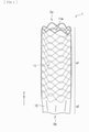
- FIG. 1 is a schematic perspective view of an outline configuration example of a stent graft (a stent graft 1) according to one embodiment of the invention.
- the stent graft 1 may be an instrument that is used, for example, upon treatment of arterial dissection, etc. by utilizing the OSG method.
- the stent graft 1 is to be placed at a part to be treated (for example, inside a blood vessel such as an aorta), as will be described later.
- the stent graft 1 has a tubular (cylindrical) structure that extends along its own axis direction (a Z-axis direction).
- the stent graft 1 includes a stent 11 and a graft 12. It is to be noted that the stent graft 1 has a length in the axis direction, for example, from about 2 cm to about 30 cm. Further, the stent graft 1 has an outer diameter at the time of its expansion, for example, from about 6 mm to about 46 mm.
- the stent 11 includes one or a plurality of wire members (wires) 11w, and has a tubular (cylindrical) structure in this example.
- the tubular structure is configured by a mesh structure.
- the tubular mesh structure is provided by weaving the one or the plurality of wire members 11w into a predetermined pattern. It is to be noted that examples of the patterns of weaving may include plane weave, twill weave, or stockinet.
- the tubular mesh structure may be provided by disposing one or more wire members 11w that are bent in a zigzag form and processed into a tubular shape.
- the stent 11 is disposed in a region corresponding to part of the graft 12 and extending in the axis direction of the graft 12, in this example.
- the stent graft 1 has a stent disposed region a1 and a stent non-disposed region a2 in its own axis direction.
- the stent disposed region a1 is a region in which the stent 11 is disposed.
- the stent non-disposed region a2 is a region in which the stent 11 is not disposed.
- the stent non-disposed region a2 is provided on side of an end Eb of the stent graft 1, and the stent disposed region a1 extends to an end Ea of the stent graft 1 on the end Ea side of the stent graft 1, as illustrated in FIG. 1 .
- the end Eb is one end of the stent graft 1
- the end Ea is the other end of the stent graft 1.
- a length of the stent 11 in its own axis direction (a length of the stent disposed region a1) is, for example, from about 2 cm to about 25 cm.
- a metal wire member may be preferable as a material of the wire member 11w described above.
- a shape-memory alloy may be preferably employed.
- the shape-memory alloy is provided with a shape-memory effect, superelasticity, etc. by a thermal process.
- stainless-steel, tantalum (Ta), titanium (Ti), platinum (Pt), gold (Au), tungsten (W), etc. may be used as the material of the wire member 11w, depending on the application.
- an alloy of nickel (Ni) and Ti, an alloy of copper (Cu), zinc (Zn), and X (X is aluminum (Al), iron (Fe), etc.), an alloy of Ni, Ti, and X (X is Fe, Cu, vanadium (V), cobalt (Co), etc.), etc. may be preferably used.
- synthetic resin, etc. may be used as the foregoing wire member 11w.
- a metal wire member having a surface covered with Au, Pt, etc. by a method such as plating may be used as the wire member 11w.
- a complex wire member in which a core material is covered with an alloy may be used as the wire member 11w.
- the core material includes a material that does not transmit radiation, such as Au or Pt.
- the graft 12 has a tubular (cylindrical) shape as illustrated in FIG. 1 .
- the graft 12 is so disposed as to cover (coat) part or all of the stent 11.
- the graft 12 is so disposed as to cover outer circumference side of the stent 11 (the wire member 11w) in this example.
- the graft 12 is coupled to the stent 11 by a method such as sewing, attaching, or welding.
- the graft 12 covers the stent 11 and is coupled to the stent 11 so as not to influence expansion and contraction of the stent 11.
- a coupling part at which the graft 12 and the stent 11 are coupled to each other is provided appropriately at a location such as at both ends of the stent 11 or in the middle of the stent 11.
- Examples of a material that may be used as the graft 12 described above include: thermoplastic resin that is formed in to a tubular shape by a molding method such as extrusion molding or blow molding; a tubular-shaped knitted or woven material including a fiber of thermoplastic resin or a super-fine metal wire; a tubular-shaped non-woven fabric including thermoplastic resin or super-fine metal; a tubular-shaped flexible resin sheet or a tubular-shaped porous sheet; a structure derived from resin that has been dissolved in a solvent and is formed into a thin tubular shape by electrospinning; etc.
- a publicly-known material knitted or woven in plane weave, twill weave, etc. may be used.
- a knitted or woven material with a crimp such as that subjected to a crimping process may also be used.
- the tubular-shaped knitted or woven material of a fiber of thermoplastic resin may be preferable, and the tubular-shaped material woven in twill weave of the fiber of the thermoplastic resin may be more preferable among the foregoing materials.
- One reason for this is that such a material is superior in strength, pore rate, productivity, etc.
- thermoplastic resin for example, resin having durability and causing a small tissue reaction may be used.
- resin having durability and causing a small tissue reaction include: polyolefin such as polyethylene, polypropylene, or an ethylene- ⁇ -olefin copolymer; polyester such as polyamide, polyurethane, polyethylene terephthalate, polybutylene terephthalate, polycyclohexane terephthalate, or polyethylene-2, 6-naphthalate; fluororesin such as polyethylene fluoride or polypropylene fluoride, etc.
- the polyester such as polyethylene terephthalate or the fluororesin such as polyethylene fluoride or polypropylene fluoride that are chemically stable, have great durability, and cause a small tissue reaction may be preferably used in particular.
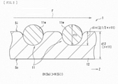
- FIG. 2 is a schematic cross-sectional view of the detailed configuration example of the stent graft 1.
- the graft 12 has a thickness d12 that is greater than a diameter r11 of the wire member 11w of the stent 11 (d12 > r11), as illustrated in FIG. 2 .
- the graft 12 has a structure with a greater thickness (a thick structure) compared to an existing typical graft (for example, a graft 102 according to a comparative example described later).
- the foregoing thickness d12 of the graft 12 is from about 0.15 mm to about 0.60 mm (for example, 0.4 mm).
- the foregoing diameter r11 of the wire member 11w is from about 0.10 mm to about 0.50 mm (for example, 0.3 mm).
- a part, of the wire member 11w, corresponding to half (1/2) or more of the diameter r11 of the wire member 11w is embedded in side of an inner circumferential surface Si of the graft 12.
- din represents an embedded length, i.e., a length (a depth) of the part, of the wire member 11w, that is embedded in the inner circumferential surface Si side of the graft 12.
- the graft 12 has liquid retainability H(So), on side of an outer circumferential surface So of the graft 12, that is greater than liquid retainability H(Si), on the inner circumferential surface Si side of the graft 12 (H(So) > H(Si)), as illustrated in FIG. 2 .
- liquid permeability on the outer circumferential surface So side of the graft 12 is greater than liquid permeability on the inner circumferential surface Si side of the graft 12.
- each of the liquid retainability and the liquid permeability of the graft 12 described above is defined by magnitude of a voidage on the outer circumferential surface So side and the inner circumferential surface Si side of the graft 12.
- the higer the voidage is, the greater each of the liquid retainability and the liquid permeability becomes.
- the lower the voidage is, the smaller each of the liquid retainability and the liquid permeability becomes.
- the stent graft 1 is able to expand or retain a lumen by being placed at a part to be treated (for example, inside a blood vessel such as an aorta) upon treatment, for example, of arterial dissection, etc. of a patient. Further, in particular, the stent graft 1 is used, for example, upon treatment utilizing the OSG method that is one of the methods of treating arterial dissection at a thoracic aorta, etc.
- FIG. 3 is a schematic diagram illustrating an example of a method of using the stent graft 1 upon the foregoing treatment.
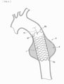
- FIG. 4 is a schematic diagram illustrating an example of a state of placement of the stent graft 1 upon the foregoing treatment. It is to be noted the following description refers to an example case where an artery 9 (a thoracic aorta) that is a blood vessel to be treated is a descending aorta. Further, FIGs. 3 and 4 each illustrate an aneurysm at the artery 9 to be treated as an aneurysm A.
- the stent graft 1 reduced in diameter is inserted from an opening "h" with the use of an unillustrated instrument dedicated to a predetermined delivery, after a thoracic part of a patient is opened (see an arrow PI).
- the opening h derives from incision of part of the artery 9.
- the stent graft 1 is so inserted that the end Ea of the stent graft 1 is on tip end side, and the end Eb (the stent non-disposed region a2 side) is on base end side, as illustrated in FIG. 3 .
- the end Ea of the stent graft 1 is caused to reach a part located farther than a part to be treated in the artery 9 (a part located farther than a part near a location provided with the aneurysm A), by the use of the delivery-dedicated instrument.
- the diameter of the stent graft 1 is increased by utilizing self-expanding force of the stent graft 1.
- the stent graft 1 is fixed to an inner wall of the artery 9, as illustrated in FIG. 4 .
- This expands or retains the lumen of the artery 9 near the location provided with the aneurysm A.
- an anastomosis is made between the base end side (the end Eb side) of the stent graft 1 and the artery 9 (the blood vessel of the patient) by suturing.
- another anastomosis may be made between the foregoing anastomosis part and another artificial blood vessel different from the stent graft 1, on an as-needed basis.
- An inner circumference of the aneurysm A is covered by the stent graft 1 as illustrated in FIG. 4 in the foregoing manner.
- This allows blood to flow through inside of the stent graft 1, and prevents the aneurysm A from being influenced by a blood pressure, etc.
- a blood pressure etc.
- it is possible to prevent an increase in diameter of the aneurysm A and a rupture of the blood vessel at the aneurysm A. It is also possible to maintain a blood flow at the aneurysm A.
- the foregoing treatment method utilizing the OSG method has the following advantages in particular, compared with a treatment method (an existing treatment method) that inserts a catheter from a base of a leg (a groin) of a patient and thereby delivers a stent graft to a part to be treated. That is, it is possible to perform a procedure on a part having an important branch (for example, an aortic arch) which has caused extreme difficulty in procedure by the existing treatment method.
- an important branch for example, an aortic arch
- the OSG method omits making the anastomosis between the tip end side (the end Ea side) of the stent graft 1 and the descending aorta. It is therefore easier to make an anastomosis.
- the OSG method makes it possible to set a transplantation range of the artificial blood vessel to a great range. This makes it possible to perform a surgical procedure for a complication near the treated part, which is also advantageous.
- the stent graft applied to the OSG method is not introduced from a groin, unlike the foregoing existing treatment method. This eliminates the necessity to cause the stent graft to pass through a fine blood vessel. It is therefore possible for the stent graft to have an outer diameter that is great (thick) to some extent even in a state where the stent graft is reduced in diameter.
- FIG. 5 is a schematic cross-sectional view of a configuration example of a stent graft (a stent graft 100) according to a comparative example.
- the stent graft 100 according to the comparative example corresponds to the stent graft 1 according to the embodiment illustrated in FIGs. 1 and 2 except that a magnitude relationship in size between the stent 11 and the graft 12 is changed (a stent 101 and a graft 102 are provided in place of the stent 11 and the graft 12).
- Other configuration of the stent graft 100 is basically similar to that of the stent graft 1.
- the graft 102 has a thickness d102 that is smaller than a diameter r101 of a wire member 101w of the stent 101 (d102 ⁇ r101), as illustrated in FIG. 5 .
- the graft 102 has a structure that has a thickness as small as possible.
- the stent graft 100 is applied to the existing treatment method described above.
- the stent graft 100 in a case where the stent graft 100 is inserted from a groin of a patient, it is necessary to mount the stent graft 100 on an unillustrated fine catheter having a diameter, for example, from about 20 Fr to about 26 Fr. Accordingly, it is necessary to make small the outer diameter of the stent graft 100 in a state after the diameter of the stent graft 100 is reduced.
- the thickness d102 of the graft 102 of the stent graft 100 is therefore set to be as small as possible (as thin as possible).
- the thickness d102 of the graft 102 described above is from about 0.05 mm to about 0.15 mm (for example, 0.10 mm), and the diameter r101 of the wire member 101w is from about 0.20 mm to about 0.50 mm (for example, 0.45 mm).
- the stent graft 100 according to the comparative example is applied to, for example, the OSG method.
- the graft 102 may be possibly ripped upon suturing of the end of the stent graft 100 or at any other timing, which causes difficulty in making an anastomosis.
- One reason for this is insufficiency in strength of the graft 102 in a case where the thickness d102 of the graft 102 is small (d102 ⁇ r101) as described above.
- leakage of blood from the graft 102 may be increased, which may possibly cause insufficiency in treating the arterial dissection, etc.
- the small thickness d102 of the graft 102 causes an increase in leakage of blood from a pinhole caused upon making an anastomosis between the graft 102 and a blood vessel of the patient or an artificial blood vessel. This may cause insufficiency in blocking blood flowing into a false lumen of the aneurysm or the arterial dissection, which may possibly cause insufficiency in an effect of the treatment. Therefore, the stent graft 100 according to the comparative example may decrease convenience, for example, upon the treatment of the arterial dissection, etc. utilizing the OSG method.
- the thickness d12 of the graft 12 is greater than the diameter r11 of the wire member 11w of the stent 11 (d12 > r11), as illustrated in FIG. 2 .
- the graft 12 has a structure with a greater thickness. This makes it possible for the stent graft 1 to reduce the possibility of ripping of the graft 12 upon the suturing of the end Eb, etc., upon the treatment of the arterial dissection, etc. utilizing the foregoing OSG method, for example. Further, this makes it also possible for the stent graft 1 to suppress the leakage of blood from the graft 12 or the pinhole described above, upon the treatment of the arterial dissection, etc. utilizing the foregoing OSG method, for example.
- the graft 12 is so disposed as to cover at least the outer circumference side of the stent 11 as illustrated in FIG. 2 .
- the part, of the wire member 11w of the stent 11, corresponding to half or more of the diameter r11 of the wire member 11w is embedded in the inner circumferential surface Si side of the graft 12, as illustrated in FIG. 2 .
- the embedded length din ⁇ ⁇ (1/2) ⁇ r11 ⁇ is satisfied, as illustrated in FIG. 2 .
- the stent graft 1 when the stent graft 1 expands, it is easier for a circumference of the stent 11 to be surrounded by the graft 12. This makes it difficult for the inner circumference side of the stent 11 to be protruded from the inner circumferential surface Si of the graft 12. It is therefore difficult for the blood flow inside the stent graft 1 to be disrupted (for example, see a blood flow F illustrated in FIG. 2 ).
- the stent graft 100 according to the comparative example described above has a state where the embedded length din ⁇ ⁇ (1/2) ⁇ r11 ⁇ is established, as illustrated in FIG. 5 .
- a force applied from the stent 11 is easily dispersed at the graft 12 having the great thickness (an effect of absorbing the force by the graft 12 is increased).
- a wall of a blood vessel at a diseased part is extremely weak. It is therefore extremely easy for the wall of the blood vessel to be ripped.
- what is important is that it is possible to prevent the inside of the blood vessel from being damaged as in the case of the stent graft 1.
- the liquid retainability H(So) on the outer circumferential surface So side of the graft 12 is greater than the liquid retainability H(Si) on the inner circumferential surface Si side of the graft 12 (H(So) > H(Si)), as illustrated in FIG. 2 .
- the liquid permeability on the outer circumferential surface So side of the graft 12 is greater than the liquid permeability on the inner circumferential surface Si side of the graft 12.
- the graft having low liquid retainability has an advantage that a blood clot is less likely to be generated.
- the graft having low liquid retainability includes, for example, a knitted or woven material that is knitted or woven tightly, or a film having low liquid transmission rate.
- a graft has drawbacks that it is difficult to make an anastomosis between the graft and a blood vessel of a patient or an artificial blood vessel, and that such a graft has poor compatibility with a surrounding tissue (such a graft has low characteristics in attachment to the surrounding tissue).
- a graft having high liquid retainability has advantages that it is easy to make an anastomosis between the graft and a blood vessel of a patient or an artificial blood vessel, and that such a graft has high compatibility with a surrounding tissue (such a graft has high characteristics in attachment to the surrounding tissue).
- the graft having high liquid retainability includes, for example, a knitted or woven material that is knitted or woven roughly, or a sponge-like film.
- such a graft causes a lot of leakage of blood from the graft, and causes insufficiency in blocking of blood flowing into a false lumen of the aneurysm or the arterial dissection, which may possibly cause insufficiency in an effect of the treatment.
- the stent graft 1 in contrast, in the stent graft 1 according to the embodiment, the outer circumferential surface So side of the graft 12 has high liquid retainability, and the inner circumferential surface Si side of the graft 12 has low liquid retainability, as described above. Therefore, the stent graft 1 according to the embodiment is able to have the advantages of each of the foregoing two types of structures. In other words, the stent graft 1 makes it easier to make an anastomosis between the graft 12 and a blood vessel of a patient or an artificial blood vessel, and increases attachment characteristics between the graft 12 and an inner circumferential surface of a blood vessel (the graft 12 has higher compatibility with a surrounding tissue). Further, the stent graft 1 makes it difficult for a blood clot to be generated on the inner circumferential surface Si side of the graft 12.
- the liquid retainability and the liquid permeability described above is achievable owing to the structure of the graft 12 that has the thickness greater than that of the existing graft (the thickness d12 of the graft 12 is greater than the diameter r11 of the wire member 11w of the stent 11), as described above.
- the structure of the graft 12 having the great thickness that allows for the above-described difference in structure between the outer circumferential surface So side of the graft 12 and the inner circumferential surface Si side of the graft 12 (for example, the difference in voidage of the porous structure of the graft 12), to thereby achieve the bilayer structure.
- the stent graft 100 according to the foregoing comparative example is so configured as not to show such liquid retainability and such liquid permeability (is so configured that the liquid retainability and the liquid permeability of the graft 102 are suppressed to be low), in order to reduce the thickness of the graft 102 as much as possible.
- the stent 11 is disposed in the region (the stent disposed region a1) corresponding to part of the graft 12 and extending in the axis direction of the graft 12, as illustrated in FIG. 1 . It is therefore easier to make an anastomosis between the end (the end Eb, in this example) of the stent graft 1 and the blood vessel of the patient or the artificial blood vessel by utilizing the stent non-disposed region a2 of the graft 12.
- the graft 12 has the thickness d12 that is greater than the diameter r11 of the wire member 11w of the stent 11, as described above. Therefore, the followings are achieved, for example. That is, it is possible to reduce a possibility of ripping of the graft 12, for example, upon treatment of arterial dissection, etc. utilizing the OSG method. Further, it is possible to reduce leakage of blood from the graft 12 or the pinhole described above, for example, upon the treatment of arterial dissection, etc. utilizing the OSG method. This makes it possible to sufficiently treat the arterial dissection, etc. Hence, it is possible to improve convenience in treatment.
- FIG. 6 is a schematic cross-sectional view of a configuration example of a stent graft (a stent graft 1A) according to Modification example 1.
- the stent graft 1A corresponds to the stent graft 1 illustrated in FIGs. 1 and 2 except that how the stent 11 is covered with the graft 12 is changed.
- Other configuration of the stent graft 1A is basically similar to that of the stent graft 1.
- the graft 12 is so disposed as to cover the outer circumference side of the stent 11 (the wire member 11w), as illustrated in FIG. 2 .
- the graft 12 is so disposed as to cover both the outer circumference side and the inner circumference side of the stent 11 (the wire member 11w), as illustrated in FIG. 6 .
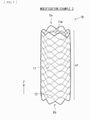
- FIG. 7 is a schematic perspective view of an outline configuration example of a stent graft (a stent graft 1B) according to Modification example 2.
- the stent graft 1B corresponds to the stent graft 1 illustrated in FIGs. 1 and 2 except that a region in which the stent 11 is disposed is changed.
- Other configuration of the stent graft 1B is basically similar to that of the stent graft 1.
- the stent 11 is disposed in the region corresponding to part of the graft 12 and extending in the axis direction of the graft 12, as illustrated in FIG. 1 .
- the stent graft 1 has the stent disposed region a1 and the stent non-disposed region a2 in the axis direction of the stent graft 1.
- the stent 11 is disposed in a region corresponding to all of the graft 12 and extending in the axis direction of the graft 12, as illustrated in FIG. 7 .
- the stent graft 1B includes only the stent disposed region a1 in the axis direction of the stent graft 1B, and does not include the stent non-disposed region a2.
- the stent disposed region a1 extends from one end Eb of the stent graft 1B to the other end Eb of the stent graft 1B.
- shapes, locations, sizes, numbers, materials, etc., of the respective members described in the foregoing embodiment are non-limiting, and may respectively be any other shape, location, size, number, material, etc.
- the graft 12 may cover only the inner circumference side of the stent 11.
- the arranged shape (the weaving pattern) of the wire member 11w of the stent 11 is not limited to those referred to in the foregoing embodiment, and may be any other arranged shape.
- the embedded length din of the wire member 11w of the stent 11 may be smaller than the half of the diameter r11 of the wire member 11w. In other words, din ⁇ ⁇ (1/2) ⁇ r11 ⁇ may be satisfied.
- the diameters r11 of the respective wire members 11w may be different from each other. In this case, it is sufficient that the diameter r11 of at least one of the plurality of wire members 11w satisfies each of the foregoing relational expressions.
- the foregoing embodiment, etc. are described with reference to an example case where only one stent 11 is disposed in the stent graft, this is non-limiting. Two or more stents 11 may be individually disposed in the stent graft (for example, the two or more stents 11 may be disposed in the axis direction while being separated from each other).
- the foregoing embodiment, etc. have been described with reference to an example case where the liquid retainability (and the liquid permeability) on the outer circumferential surface So side of the graft 12 is greater than the liquid retainability (and the liquid permeability) on the inner circumferential surface Si side of the graft 12, this is non-limiting. That is, in contrast, the liquid retainability (and the liquid permeability) on the outer circumferential surface So side of the graft 12 is equal to or smaller than the liquid retainability (and the liquid permeability) on the inner circumferential surface Si side of the graft 12, in some cases.
- the stent graft of the invention is also applicable to treatment of a blood vessel such as any artery other than the descending aorta (for example, an ascending aorta, an aortic arch, a thoracoabdominal aorta, an abdominal aorta, an iliac artery, a femoral artery, etc.)
- a blood vessel such as any artery other than the descending aorta (for example, an ascending aorta, an aortic arch, a thoracoabdominal aorta, an abdominal aorta, an iliac artery, a femoral artery, etc.)
Landscapes
- Health & Medical Sciences (AREA)
- Gastroenterology & Hepatology (AREA)
- Pulmonology (AREA)
- Cardiology (AREA)
- Oral & Maxillofacial Surgery (AREA)
- Transplantation (AREA)
- Engineering & Computer Science (AREA)
- Biomedical Technology (AREA)
- Heart & Thoracic Surgery (AREA)
- Vascular Medicine (AREA)
- Life Sciences & Earth Sciences (AREA)
- Animal Behavior & Ethology (AREA)
- General Health & Medical Sciences (AREA)
- Public Health (AREA)
- Veterinary Medicine (AREA)
- Prostheses (AREA)
Applications Claiming Priority (2)
| Application Number | Priority Date | Filing Date | Title |
|---|---|---|---|
| JP2015145831A JP6200465B2 (ja) | 2015-07-23 | 2015-07-23 | ステントグラフト |
| PCT/JP2016/053172 WO2017013885A1 (ja) | 2015-07-23 | 2016-02-03 | ステントグラフト |
Publications (3)
| Publication Number | Publication Date |
|---|---|
| EP3326581A1 EP3326581A1 (en) | 2018-05-30 |
| EP3326581A4 EP3326581A4 (en) | 2019-03-13 |
| EP3326581B1 true EP3326581B1 (en) | 2022-01-19 |
Family
ID=57834391
Family Applications (1)
| Application Number | Title | Priority Date | Filing Date |
|---|---|---|---|
| EP16827451.2A Active EP3326581B1 (en) | 2015-07-23 | 2016-02-03 | Stent graft |
Country Status (6)
| Country | Link |
|---|---|
| EP (1) | EP3326581B1 (zh) |
| JP (1) | JP6200465B2 (zh) |
| KR (2) | KR20170120657A (zh) |
| CN (1) | CN107427356A (zh) |
| TW (1) | TWI601519B (zh) |
| WO (1) | WO2017013885A1 (zh) |
Families Citing this family (4)
| Publication number | Priority date | Publication date | Assignee | Title |
|---|---|---|---|---|
| JP6564757B2 (ja) * | 2016-11-11 | 2019-08-21 | 日本ライフライン株式会社 | 治療装置 |
| CN111225637A (zh) * | 2017-11-06 | 2020-06-02 | Ea制药株式会社 | 支架以及包括该支架的医疗设备 |
| JP6698262B2 (ja) | 2018-03-09 | 2020-05-27 | 日本ライフライン株式会社 | 大動脈治療装置 |
| WO2023233374A1 (en) * | 2022-06-03 | 2023-12-07 | Medibrane Ltd | Stent assemblies and method of manufacturing |
Family Cites Families (16)
| Publication number | Priority date | Publication date | Assignee | Title |
|---|---|---|---|---|
| JP3507503B2 (ja) * | 1995-03-10 | 2004-03-15 | インプラ・インコーポレーテッド | 体腔内用の封止型ステント及びその製造方法並びにその体腔内への導入方法 |
| US6156064A (en) * | 1998-08-14 | 2000-12-05 | Schneider (Usa) Inc | Stent-graft-membrane and method of making the same |
| DE60032151T2 (de) * | 1999-09-01 | 2007-09-27 | Boston Scientific Scimed, Inc., Maple Grove | Rohrförmige stent-gewebe kompositvorrichtung und herstellungsverfahren dafür |
| KR20050091040A (ko) * | 2002-12-30 | 2005-09-14 | 안지오테크 인터내셔날 아게 | 실크 함유 스텐트 이식편 |
| US7763063B2 (en) | 2003-09-03 | 2010-07-27 | Bolton Medical, Inc. | Self-aligning stent graft delivery system, kit, and method |
| US7682381B2 (en) * | 2004-04-23 | 2010-03-23 | Boston Scientific Scimed, Inc. | Composite medical textile material and implantable devices made therefrom |
| US20060058867A1 (en) * | 2004-09-15 | 2006-03-16 | Thistle Robert C | Elastomeric radiopaque adhesive composite and prosthesis |
| JP2008540022A (ja) * | 2005-05-17 | 2008-11-20 | ナイキャスト リミテッド | 植込み可能な荷電性医療装置 |
| JP2008099995A (ja) | 2006-10-20 | 2008-05-01 | Guroobu Kk | ステント及びステントグラフト |
| US20080208325A1 (en) * | 2007-02-27 | 2008-08-28 | Boston Scientific Scimed, Inc. | Medical articles for long term implantation |
| US9539360B2 (en) * | 2011-10-07 | 2017-01-10 | W. L. Gore & Associaes, Inc. | Puncturable and resealable graft |
| CN102430157B (zh) * | 2011-11-29 | 2013-11-27 | 武汉纺织大学 | 一种内覆膜的医用支架及其制备方法 |
| CN202740157U (zh) * | 2012-08-07 | 2013-02-20 | 湖南瑞康通科技发展有限公司 | 脑动脉瘤支架系统 |
| CA3088022C (en) * | 2012-08-15 | 2023-02-28 | Flow Forward Medical, Inc. | Blood pump systems and methods |
| CN104586537B (zh) * | 2013-10-31 | 2017-05-10 | 微创心脉医疗科技(上海)有限公司 | 一种覆膜支架 |
| CN104758086B (zh) * | 2015-04-20 | 2016-08-17 | 湖南埃普特医疗器械有限公司 | 脑动脉瘤腔内血管重建装置 |
-
2015
- 2015-07-23 JP JP2015145831A patent/JP6200465B2/ja active Active
-
2016
- 2016-02-03 EP EP16827451.2A patent/EP3326581B1/en active Active
- 2016-02-03 WO PCT/JP2016/053172 patent/WO2017013885A1/ja unknown
- 2016-02-03 KR KR1020177026795A patent/KR20170120657A/ko not_active IP Right Cessation
- 2016-02-03 KR KR1020207016995A patent/KR20200072567A/ko not_active Application Discontinuation
- 2016-02-03 CN CN201680017005.2A patent/CN107427356A/zh active Pending
- 2016-06-29 TW TW105120506A patent/TWI601519B/zh not_active IP Right Cessation
Also Published As
| Publication number | Publication date |
|---|---|
| KR20170120657A (ko) | 2017-10-31 |
| EP3326581A1 (en) | 2018-05-30 |
| JP6200465B2 (ja) | 2017-09-20 |
| EP3326581A4 (en) | 2019-03-13 |
| CN107427356A (zh) | 2017-12-01 |
| WO2017013885A1 (ja) | 2017-01-26 |
| JP2017023464A (ja) | 2017-02-02 |
| KR20200072567A (ko) | 2020-06-22 |
| TWI601519B (zh) | 2017-10-11 |
| TW201703739A (zh) | 2017-02-01 |
Similar Documents
| Publication | Publication Date | Title |
|---|---|---|
| US20230293284A1 (en) | Endoluminal prosthesis having multiple branches or fenestrations and methods of deployment | |
| US20230016361A1 (en) | Low profile stent graft and delivery system | |
| JP5643806B2 (ja) | 巻き上げ式密封アセンブリを備えた分岐血管プロテーゼ | |
| US20090259290A1 (en) | Fenestration Segment Stent-Graft and Fenestration Method | |
| EP2777607B1 (en) | Prosthesis having an everting pivoting fenestration | |
| WO2017180579A1 (en) | Gutter filling stent-graft and method | |
| US10596015B2 (en) | Intraluminal vascular prosthesis | |
| EP3326581B1 (en) | Stent graft | |
| US20070106368A1 (en) | Graft-stent assembly | |
| WO2007028112A2 (en) | Methods and apparatus for treatment of aneurysms adjacent to branch arteries | |
| EP2833829B1 (en) | Low profile stent graft and delivery system | |
| US11872146B2 (en) | Aortic filter and flow diverter and methods for use thereof | |
| EP3326582B1 (en) | Stent graft with top mesh stent | |
| US20070150042A1 (en) | Stents with beveled ends and methods of use thereof | |
| EP3431053B1 (en) | Therapeutic device | |
| EP3431039A1 (en) | Non-cylindrical mesh top stent with twisted sections | |
| WO2018087947A1 (ja) | 治療装置 | |
| WO2020065742A1 (ja) | 治療装置 | |
| JP2004049584A (ja) | 血管の治療具 | |
| US11617668B2 (en) | Branched stent and stent system | |
| JP2022033017A (ja) | 液体流出装置 |
Legal Events
| Date | Code | Title | Description |
|---|---|---|---|
| STAA | Information on the status of an ep patent application or granted ep patent |
Free format text: STATUS: THE INTERNATIONAL PUBLICATION HAS BEEN MADE |
|
| PUAI | Public reference made under article 153(3) epc to a published international application that has entered the european phase |
Free format text: ORIGINAL CODE: 0009012 |
|
| STAA | Information on the status of an ep patent application or granted ep patent |
Free format text: STATUS: REQUEST FOR EXAMINATION WAS MADE |
|
| 17P | Request for examination filed |
Effective date: 20171220 |
|
| AK | Designated contracting states |
Kind code of ref document: A1 Designated state(s): AL AT BE BG CH CY CZ DE DK EE ES FI FR GB GR HR HU IE IS IT LI LT LU LV MC MK MT NL NO PL PT RO RS SE SI SK SM TR |
|
| AX | Request for extension of the european patent |
Extension state: BA ME |
|
| RIN1 | Information on inventor provided before grant (corrected) |
Inventor name: SAKAI, MASAMUNE Inventor name: HURUYA, HIDEKI |
|
| DAV | Request for validation of the european patent (deleted) | ||
| DAX | Request for extension of the european patent (deleted) | ||
| A4 | Supplementary search report drawn up and despatched |
Effective date: 20190212 |
|
| RIC1 | Information provided on ipc code assigned before grant |
Ipc: A61F 2/07 20130101AFI20190206BHEP |
|
| GRAP | Despatch of communication of intention to grant a patent |
Free format text: ORIGINAL CODE: EPIDOSNIGR1 |
|
| STAA | Information on the status of an ep patent application or granted ep patent |
Free format text: STATUS: GRANT OF PATENT IS INTENDED |
|
| INTG | Intention to grant announced |
Effective date: 20210915 |
|
| GRAS | Grant fee paid |
Free format text: ORIGINAL CODE: EPIDOSNIGR3 |
|
| STAA | Information on the status of an ep patent application or granted ep patent |
Free format text: STATUS: GRANT OF PATENT IS INTENDED |
|
| GRAA | (expected) grant |
Free format text: ORIGINAL CODE: 0009210 |
|
| STAA | Information on the status of an ep patent application or granted ep patent |
Free format text: STATUS: THE PATENT HAS BEEN GRANTED |
|
| AK | Designated contracting states |
Kind code of ref document: B1 Designated state(s): AL AT BE BG CH CY CZ DE DK EE ES FI FR GB GR HR HU IE IS IT LI LT LU LV MC MK MT NL NO PL PT RO RS SE SI SK SM TR |
|
| REG | Reference to a national code |
Ref country code: GB Ref legal event code: FG4D |
|
| REG | Reference to a national code |
Ref country code: CH Ref legal event code: EP |
|
| REG | Reference to a national code |
Ref country code: DE Ref legal event code: R096 Ref document number: 602016068521 Country of ref document: DE |
|
| REG | Reference to a national code |
Ref country code: AT Ref legal event code: REF Ref document number: 1463348 Country of ref document: AT Kind code of ref document: T Effective date: 20220215 |
|
| REG | Reference to a national code |
Ref country code: IE Ref legal event code: FG4D |
|
| REG | Reference to a national code |
Ref country code: LT Ref legal event code: MG9D |
|
| REG | Reference to a national code |
Ref country code: NL Ref legal event code: MP Effective date: 20220119 |
|
| REG | Reference to a national code |
Ref country code: AT Ref legal event code: MK05 Ref document number: 1463348 Country of ref document: AT Kind code of ref document: T Effective date: 20220119 |
|
| PG25 | Lapsed in a contracting state [announced via postgrant information from national office to epo] |
Ref country code: NL Free format text: LAPSE BECAUSE OF FAILURE TO SUBMIT A TRANSLATION OF THE DESCRIPTION OR TO PAY THE FEE WITHIN THE PRESCRIBED TIME-LIMIT Effective date: 20220119 |
|
| PG25 | Lapsed in a contracting state [announced via postgrant information from national office to epo] |
Ref country code: SE Free format text: LAPSE BECAUSE OF FAILURE TO SUBMIT A TRANSLATION OF THE DESCRIPTION OR TO PAY THE FEE WITHIN THE PRESCRIBED TIME-LIMIT Effective date: 20220119 Ref country code: RS Free format text: LAPSE BECAUSE OF FAILURE TO SUBMIT A TRANSLATION OF THE DESCRIPTION OR TO PAY THE FEE WITHIN THE PRESCRIBED TIME-LIMIT Effective date: 20220119 Ref country code: PT Free format text: LAPSE BECAUSE OF FAILURE TO SUBMIT A TRANSLATION OF THE DESCRIPTION OR TO PAY THE FEE WITHIN THE PRESCRIBED TIME-LIMIT Effective date: 20220519 Ref country code: NO Free format text: LAPSE BECAUSE OF FAILURE TO SUBMIT A TRANSLATION OF THE DESCRIPTION OR TO PAY THE FEE WITHIN THE PRESCRIBED TIME-LIMIT Effective date: 20220419 Ref country code: LT Free format text: LAPSE BECAUSE OF FAILURE TO SUBMIT A TRANSLATION OF THE DESCRIPTION OR TO PAY THE FEE WITHIN THE PRESCRIBED TIME-LIMIT Effective date: 20220119 Ref country code: HR Free format text: LAPSE BECAUSE OF FAILURE TO SUBMIT A TRANSLATION OF THE DESCRIPTION OR TO PAY THE FEE WITHIN THE PRESCRIBED TIME-LIMIT Effective date: 20220119 Ref country code: ES Free format text: LAPSE BECAUSE OF FAILURE TO SUBMIT A TRANSLATION OF THE DESCRIPTION OR TO PAY THE FEE WITHIN THE PRESCRIBED TIME-LIMIT Effective date: 20220119 Ref country code: BG Free format text: LAPSE BECAUSE OF FAILURE TO SUBMIT A TRANSLATION OF THE DESCRIPTION OR TO PAY THE FEE WITHIN THE PRESCRIBED TIME-LIMIT Effective date: 20220419 |
|
| PGFP | Annual fee paid to national office [announced via postgrant information from national office to epo] |
Ref country code: IT Payment date: 20220502 Year of fee payment: 7 |
|
| PG25 | Lapsed in a contracting state [announced via postgrant information from national office to epo] |
Ref country code: PL Free format text: LAPSE BECAUSE OF FAILURE TO SUBMIT A TRANSLATION OF THE DESCRIPTION OR TO PAY THE FEE WITHIN THE PRESCRIBED TIME-LIMIT Effective date: 20220119 Ref country code: LV Free format text: LAPSE BECAUSE OF FAILURE TO SUBMIT A TRANSLATION OF THE DESCRIPTION OR TO PAY THE FEE WITHIN THE PRESCRIBED TIME-LIMIT Effective date: 20220119 Ref country code: GR Free format text: LAPSE BECAUSE OF FAILURE TO SUBMIT A TRANSLATION OF THE DESCRIPTION OR TO PAY THE FEE WITHIN THE PRESCRIBED TIME-LIMIT Effective date: 20220420 Ref country code: FI Free format text: LAPSE BECAUSE OF FAILURE TO SUBMIT A TRANSLATION OF THE DESCRIPTION OR TO PAY THE FEE WITHIN THE PRESCRIBED TIME-LIMIT Effective date: 20220119 Ref country code: AT Free format text: LAPSE BECAUSE OF FAILURE TO SUBMIT A TRANSLATION OF THE DESCRIPTION OR TO PAY THE FEE WITHIN THE PRESCRIBED TIME-LIMIT Effective date: 20220119 |
|
| PG25 | Lapsed in a contracting state [announced via postgrant information from national office to epo] |
Ref country code: IS Free format text: LAPSE BECAUSE OF FAILURE TO SUBMIT A TRANSLATION OF THE DESCRIPTION OR TO PAY THE FEE WITHIN THE PRESCRIBED TIME-LIMIT Effective date: 20220519 |
|
| REG | Reference to a national code |
Ref country code: CH Ref legal event code: PL |
|
| REG | Reference to a national code |
Ref country code: DE Ref legal event code: R097 Ref document number: 602016068521 Country of ref document: DE |
|
| REG | Reference to a national code |
Ref country code: BE Ref legal event code: MM Effective date: 20220228 |
|
| PG25 | Lapsed in a contracting state [announced via postgrant information from national office to epo] |
Ref country code: SM Free format text: LAPSE BECAUSE OF FAILURE TO SUBMIT A TRANSLATION OF THE DESCRIPTION OR TO PAY THE FEE WITHIN THE PRESCRIBED TIME-LIMIT Effective date: 20220119 Ref country code: SK Free format text: LAPSE BECAUSE OF FAILURE TO SUBMIT A TRANSLATION OF THE DESCRIPTION OR TO PAY THE FEE WITHIN THE PRESCRIBED TIME-LIMIT Effective date: 20220119 Ref country code: RO Free format text: LAPSE BECAUSE OF FAILURE TO SUBMIT A TRANSLATION OF THE DESCRIPTION OR TO PAY THE FEE WITHIN THE PRESCRIBED TIME-LIMIT Effective date: 20220119 Ref country code: MC Free format text: LAPSE BECAUSE OF FAILURE TO SUBMIT A TRANSLATION OF THE DESCRIPTION OR TO PAY THE FEE WITHIN THE PRESCRIBED TIME-LIMIT Effective date: 20220119 Ref country code: LU Free format text: LAPSE BECAUSE OF NON-PAYMENT OF DUE FEES Effective date: 20220203 Ref country code: EE Free format text: LAPSE BECAUSE OF FAILURE TO SUBMIT A TRANSLATION OF THE DESCRIPTION OR TO PAY THE FEE WITHIN THE PRESCRIBED TIME-LIMIT Effective date: 20220119 Ref country code: DK Free format text: LAPSE BECAUSE OF FAILURE TO SUBMIT A TRANSLATION OF THE DESCRIPTION OR TO PAY THE FEE WITHIN THE PRESCRIBED TIME-LIMIT Effective date: 20220119 Ref country code: CZ Free format text: LAPSE BECAUSE OF FAILURE TO SUBMIT A TRANSLATION OF THE DESCRIPTION OR TO PAY THE FEE WITHIN THE PRESCRIBED TIME-LIMIT Effective date: 20220119 |
|
| PLBE | No opposition filed within time limit |
Free format text: ORIGINAL CODE: 0009261 |
|
| STAA | Information on the status of an ep patent application or granted ep patent |
Free format text: STATUS: NO OPPOSITION FILED WITHIN TIME LIMIT |
|
| PG25 | Lapsed in a contracting state [announced via postgrant information from national office to epo] |
Ref country code: AL Free format text: LAPSE BECAUSE OF FAILURE TO SUBMIT A TRANSLATION OF THE DESCRIPTION OR TO PAY THE FEE WITHIN THE PRESCRIBED TIME-LIMIT Effective date: 20220119 |
|
| 26N | No opposition filed |
Effective date: 20221020 |
|
| GBPC | Gb: european patent ceased through non-payment of renewal fee |
Effective date: 20220419 |
|
| PG25 | Lapsed in a contracting state [announced via postgrant information from national office to epo] |
Ref country code: LI Free format text: LAPSE BECAUSE OF NON-PAYMENT OF DUE FEES Effective date: 20220228 Ref country code: IE Free format text: LAPSE BECAUSE OF NON-PAYMENT OF DUE FEES Effective date: 20220203 Ref country code: GB Free format text: LAPSE BECAUSE OF NON-PAYMENT OF DUE FEES Effective date: 20220419 Ref country code: FR Free format text: LAPSE BECAUSE OF NON-PAYMENT OF DUE FEES Effective date: 20220319 Ref country code: CH Free format text: LAPSE BECAUSE OF NON-PAYMENT OF DUE FEES Effective date: 20220228 |
|
| PG25 | Lapsed in a contracting state [announced via postgrant information from national office to epo] |
Ref country code: SI Free format text: LAPSE BECAUSE OF FAILURE TO SUBMIT A TRANSLATION OF THE DESCRIPTION OR TO PAY THE FEE WITHIN THE PRESCRIBED TIME-LIMIT Effective date: 20220119 Ref country code: BE Free format text: LAPSE BECAUSE OF NON-PAYMENT OF DUE FEES Effective date: 20220228 |
|
| PG25 | Lapsed in a contracting state [announced via postgrant information from national office to epo] |
Ref country code: IT Free format text: LAPSE BECAUSE OF NON-PAYMENT OF DUE FEES Effective date: 20230203 |
|
| PG25 | Lapsed in a contracting state [announced via postgrant information from national office to epo] |
Ref country code: HU Free format text: LAPSE BECAUSE OF FAILURE TO SUBMIT A TRANSLATION OF THE DESCRIPTION OR TO PAY THE FEE WITHIN THE PRESCRIBED TIME-LIMIT; INVALID AB INITIO Effective date: 20160203 |
|
| PG25 | Lapsed in a contracting state [announced via postgrant information from national office to epo] |
Ref country code: MK Free format text: LAPSE BECAUSE OF FAILURE TO SUBMIT A TRANSLATION OF THE DESCRIPTION OR TO PAY THE FEE WITHIN THE PRESCRIBED TIME-LIMIT Effective date: 20220119 Ref country code: CY Free format text: LAPSE BECAUSE OF FAILURE TO SUBMIT A TRANSLATION OF THE DESCRIPTION OR TO PAY THE FEE WITHIN THE PRESCRIBED TIME-LIMIT Effective date: 20220119 |
|
| PGFP | Annual fee paid to national office [announced via postgrant information from national office to epo] |
Ref country code: DE Payment date: 20240219 Year of fee payment: 9 |