EP3324859B1 - Werkzeugaufnahmeaufsatz für chirurgische bohrmaschine mit zusätzlicher manueller antriebseinheit und chirurgische bohrmaschine - Google Patents
Werkzeugaufnahmeaufsatz für chirurgische bohrmaschine mit zusätzlicher manueller antriebseinheit und chirurgische bohrmaschine Download PDFInfo
- Publication number
- EP3324859B1 EP3324859B1 EP16734715.2A EP16734715A EP3324859B1 EP 3324859 B1 EP3324859 B1 EP 3324859B1 EP 16734715 A EP16734715 A EP 16734715A EP 3324859 B1 EP3324859 B1 EP 3324859B1
- Authority
- EP
- European Patent Office
- Prior art keywords
- ratchet
- torque
- output
- unit
- manual
- Prior art date
- Legal status (The legal status is an assumption and is not a legal conclusion. Google has not performed a legal analysis and makes no representation as to the accuracy of the status listed.)
- Active
Links
Images


Classifications
-
- A—HUMAN NECESSITIES
- A61—MEDICAL OR VETERINARY SCIENCE; HYGIENE
- A61B—DIAGNOSIS; SURGERY; IDENTIFICATION
- A61B17/00—Surgical instruments, devices or methods
- A61B17/16—Instruments for performing osteoclasis; Drills or chisels for bones; Trepans
- A61B17/1613—Component parts
- A61B17/1622—Drill handpieces
- A61B17/1624—Drive mechanisms therefor
-
- A—HUMAN NECESSITIES
- A61—MEDICAL OR VETERINARY SCIENCE; HYGIENE
- A61B—DIAGNOSIS; SURGERY; IDENTIFICATION
- A61B17/00—Surgical instruments, devices or methods
- A61B17/16—Instruments for performing osteoclasis; Drills or chisels for bones; Trepans
-
- A—HUMAN NECESSITIES
- A61—MEDICAL OR VETERINARY SCIENCE; HYGIENE
- A61B—DIAGNOSIS; SURGERY; IDENTIFICATION
- A61B17/00—Surgical instruments, devices or methods
- A61B17/16—Instruments for performing osteoclasis; Drills or chisels for bones; Trepans
- A61B17/1613—Component parts
- A61B17/1615—Drill bits, i.e. rotating tools extending from a handpiece to contact the worked material
- A61B17/1617—Drill bits, i.e. rotating tools extending from a handpiece to contact the worked material with mobile or detachable parts
-
- A—HUMAN NECESSITIES
- A61—MEDICAL OR VETERINARY SCIENCE; HYGIENE
- A61B—DIAGNOSIS; SURGERY; IDENTIFICATION
- A61B17/00—Surgical instruments, devices or methods
- A61B17/16—Instruments for performing osteoclasis; Drills or chisels for bones; Trepans
- A61B17/1613—Component parts
- A61B17/162—Chucks or tool parts which are to be held in a chuck
-
- A—HUMAN NECESSITIES
- A61—MEDICAL OR VETERINARY SCIENCE; HYGIENE
- A61B—DIAGNOSIS; SURGERY; IDENTIFICATION
- A61B17/00—Surgical instruments, devices or methods
- A61B17/16—Instruments for performing osteoclasis; Drills or chisels for bones; Trepans
- A61B17/1613—Component parts
- A61B17/1626—Control means; Display units
-
- B—PERFORMING OPERATIONS; TRANSPORTING
- B25—HAND TOOLS; PORTABLE POWER-DRIVEN TOOLS; MANIPULATORS
- B25B—TOOLS OR BENCH DEVICES NOT OTHERWISE PROVIDED FOR, FOR FASTENING, CONNECTING, DISENGAGING, OR HOLDING
- B25B13/00—Spanners; Wrenches
- B25B13/46—Spanners; Wrenches of the ratchet type, for providing a free return stroke of the handle
- B25B13/461—Spanners; Wrenches of the ratchet type, for providing a free return stroke of the handle with concentric driving and driven member
-
- B—PERFORMING OPERATIONS; TRANSPORTING
- B25—HAND TOOLS; PORTABLE POWER-DRIVEN TOOLS; MANIPULATORS
- B25B—TOOLS OR BENCH DEVICES NOT OTHERWISE PROVIDED FOR, FOR FASTENING, CONNECTING, DISENGAGING, OR HOLDING
- B25B21/00—Portable power-driven screw or nut setting or loosening tools; Attachments for drilling apparatus serving the same purpose
-
- B—PERFORMING OPERATIONS; TRANSPORTING
- B25—HAND TOOLS; PORTABLE POWER-DRIVEN TOOLS; MANIPULATORS
- B25B—TOOLS OR BENCH DEVICES NOT OTHERWISE PROVIDED FOR, FOR FASTENING, CONNECTING, DISENGAGING, OR HOLDING
- B25B23/00—Details of, or accessories for, spanners, wrenches, screwdrivers
- B25B23/14—Arrangement of torque limiters or torque indicators in wrenches or screwdrivers
- B25B23/141—Mechanical overload release couplings
-
- B—PERFORMING OPERATIONS; TRANSPORTING
- B25—HAND TOOLS; PORTABLE POWER-DRIVEN TOOLS; MANIPULATORS
- B25F—COMBINATION OR MULTI-PURPOSE TOOLS NOT OTHERWISE PROVIDED FOR; DETAILS OR COMPONENTS OF PORTABLE POWER-DRIVEN TOOLS NOT PARTICULARLY RELATED TO THE OPERATIONS PERFORMED AND NOT OTHERWISE PROVIDED FOR
- B25F3/00—Associations of tools for different working operations with one portable power-drive means; Adapters therefor
-
- B—PERFORMING OPERATIONS; TRANSPORTING
- B25—HAND TOOLS; PORTABLE POWER-DRIVEN TOOLS; MANIPULATORS
- B25F—COMBINATION OR MULTI-PURPOSE TOOLS NOT OTHERWISE PROVIDED FOR; DETAILS OR COMPONENTS OF PORTABLE POWER-DRIVEN TOOLS NOT PARTICULARLY RELATED TO THE OPERATIONS PERFORMED AND NOT OTHERWISE PROVIDED FOR
- B25F5/00—Details or components of portable power-driven tools not particularly related to the operations performed and not otherwise provided for
- B25F5/02—Construction of casings, bodies or handles
-
- A—HUMAN NECESSITIES
- A61—MEDICAL OR VETERINARY SCIENCE; HYGIENE
- A61B—DIAGNOSIS; SURGERY; IDENTIFICATION
- A61B17/00—Surgical instruments, devices or methods
- A61B17/16—Instruments for performing osteoclasis; Drills or chisels for bones; Trepans
- A61B17/1613—Component parts
- A61B17/1622—Drill handpieces
-
- A—HUMAN NECESSITIES
- A61—MEDICAL OR VETERINARY SCIENCE; HYGIENE
- A61B—DIAGNOSIS; SURGERY; IDENTIFICATION
- A61B17/00—Surgical instruments, devices or methods
- A61B2017/00367—Details of actuation of instruments, e.g. relations between pushing buttons, or the like, and activation of the tool, working tip, or the like
- A61B2017/00407—Ratchet means
Definitions
- the invention relates to a tool holder attachment for a medical, motor-driven machine tool such as a surgical drill, which can also be referred to as a surgical screwdriver or can be used, with a drive-side coupling for attachment to a (electric) motor-driven torque-providing drive unit/motor, such as a prime mover with an electric motor and with an output-side clutch/tool receiving chuck for receiving a tool, such as a screwdriver, a drill or similar turning tools.
- a medical, motor-driven machine tool such as a surgical drill
- a surgical screwdriver which can also be referred to as a surgical screwdriver or can be used
- a drive-side coupling for attachment to a (electric) motor-driven torque-providing drive unit/motor, such as a prime mover with an electric motor and with an output-side clutch/tool receiving chuck for receiving a tool, such as a screwdriver, a drill or similar turning tools.
- bone screws are used in certain surgical procedures, for example so-called pedicle screws, which are used in spinal column surgery.
- a drilling process must first be carried out in order to then be able to place a screw in the hole drilled in the vertebral body.
- the bones/vertebrae to be treated are always brittle to varying degrees.
- a certain degree of sensitivity is therefore required in order to place the bore cleanly and to screw the screw non-destructively/i.e. inserted without damaging the vertebral body.
- the last phase of the drilling process and the last phase of the screwing process are particularly critical.
- Electromotive drive units are often used here, i.e. driving machines with an electric motor, which are either supplied with energy depending on the battery / accumulator, or access an external power supply via a cable.
- So-called wire chucks are already known, which are attachments for surgical drills that use a lever to perform a specific function.
- a wire is fed through the machine. If the lever is pulled, the wire is clamped in the machine so that it can be rotated by the drive machine. This allows the wire to be twisted into a fabric. When the lever is released, the wire can be freely moved axially and rotationally again in the machine. This principle is also followed in other medical institutions.
- a ratchet attachment for driving screwing tools is disclosed, which are used to loosen and tighten screw elements and which can be driven in either direction of rotation, with the ratchet attachment being executable both as a straight attachment and as an angled attachment.
- two spaced-apart carriers are provided which are rotatable but axially fixed relative to the housing.
- the carriers each have a ratchet toothing in their expenditure area on their end faces facing one another, which are designed in opposite directions to one another.
- a drive ring is provided opposite the respective ratchet toothing of the two drivers, which is provided on the side facing the respective driver with a corresponding ratchet toothing that can be coupled to this.
- the drive ring is mounted in the housing so that it can be displaced axially relative to it and is supported against the respective driver by means of spring devices.
- the ratchet attachment also includes a drive tool which can be rotated and passed through a polygonal opening in the driver and whose coupling end can be latched in a rotationally fixed manner into a polygonal profile of the drive ring.
- the drive ring or the respective drive ring can be pushed axially away from the driver through which the drive tool can be passed, in a position decoupled from it and at the same time in a coupled position with the other driver, which carries the screwing tool.
- the ratchet is designed/can be activated electrically, which means that, in order to ensure that the ratchet is blocked, such a high current flows in the machine that a lot of heat is generated. There is also no acoustic feedback.
- a manual ratchet for example for carrying out the drilling in the last drilling phase, or a mechanical ratchet used during thread cutting, for example as it is also used in the last phase of screwing, is not present here. Due to the cable connection, the range/freedom of movement is also severely restricted. Furthermore, this system has the disadvantage that a closed system is presented and accidental actuation of the gas trigger during manual screwing leads to sudden penetration of the screw or leads to sudden further drilling. However, this is devastating in patient use.
- Screw attachments are also known from other manufacturers, for example the "Synthes drill gun 510.01". An attachment can be attached to this drill gun, which reduces the output speed of the drill gun to approx. 300 rpm. A torque limiter must also be placed on this screw attachment for use. Unfortunately, such torque limiters are not adjustable and are only readily available in predefined values of 0.4 Nm, 0.8 Nm, 1.5 Nm and 4 Nm. Furthermore, this system cannot be used for manually screwing in and tightening screws. A tool change is therefore always necessary. In practice, the torque limitation has also proven to be inflexible. Manually screwing in a screw with a mechanical ratchet, e.g.
- Polyaxial screws are, for example, screws that have a spherical screw head that is surrounded by a housing such that the housing can be freely adjusted relative to the longitudinal axis of the screw. Pedicle screws in particular are designed in this way.
- a reduction in the physical strain on the user (surgeon) when inserting screws should also be achieved.
- the invention should in particular enable the user (surgeon) to screw in safely by machine.
- the setting of the engine speed should also be selectable in such a way that the user can precisely set the desired speed.
- a manually operable/hand power operable drive unit in the form of a ratchet is integrated, which can be operated by means of the ratchet handle/ manual actuating device of the ratchet itself can be brought into a first operating position, in which the torque is transmitted from the input clutch to the output clutch, bypassing the ratchet function, and can be brought into a second operating position, in which the two clutches are torque-separated and instead a via the Ratchet function from the ratchet handle / manual actuator entered manual torque is transmitted to the output clutch.
- a more finely adjustable manual torque transfer can then be effected. This can be done without a tool change having to be performed and without the Machine itself must be operated separately from the ratchet in some way.
- the ratchet can be constructively provided to form the ratchet with two torque transmission elements (sleeves), each of which carries teeth acting in opposite directions and can be switched into function alternately depending on the manual selection, in order to achieve right-hand or left-hand torque transmission from a manual To transfer input component such as ratchet housing on a ratchet output element such as output sleeve.
- a manual To transfer input component such as ratchet housing on a ratchet output element such as output sleeve.
- a type of selection component such as a dial/sleeve that can be manually adjusted in such a way that it comes into operative engagement with one of the torque transmission elements at a time.
- the selection component can be adjusted via the ratchet output element when it is actuated by means of the ratchet handle into a ratchet non-functional position in which the ratchet can no longer transmit any manually applied torque to the ratchet output element, but at the same time the ratchet output element can this operating position directly torque-connects the two clutches.
- the ratchet output element is a sleeve which encloses an output shaft of the tool holder in an axially displaceable but non-rotatable manner and has teeth such as spur teeth which, depending on the axial position of the ratchet output element with respect to the output shaft of the tool holder, engage with a direct/indirect output element of the input clutch is bringable.
- the ratchet output element has a kind of driving such as driving pin or protrusion, which is on the above-mentioned selection component Ratchet acts and takes it with an adjustment of the ratchet output element in its ratchet non-functional position in a position in which an operative engagement between the selection component and the two torque transmission elements of the ratchet is excluded.
- the handle can be a lever, for example, which is mounted on the housing of the ratchet in order to rotate it about the output shaft of the tool holder and thus enter a manual torque into the ratchet.
- the lever can be pivoted on the ratchet housing in the longitudinal direction of the output shaft of the tool holder and can act on the ratchet output element at its end protruding into the interior of the ratchet in order to move it axially and thus set the two above-mentioned positions for a disabling/enabling of the to set the ratchet function.
- the drive unit (housing) set up to provide torque by hand is connected to a ratchet unit/ratcheting device or a ratchet (within the housing) or is integrated with it.
- a circular rotary movement within a limited working space eg for loosening or tightening screw connections, is then efficiently made possible.
- teeth can be used inside the ratchet unit/ratchet device or ratchet, for example requiring a rotation angle of at least 10° to 15° in order to to achieve rotation of an output element.
- fine-tooth ratchets can also be used, so that a rotation angle of around 5° is sufficient to cause the screw to move.
- ratchet or ratchet is located downstream of the manual drive unit (ratchet input element/ratchet housing), i.e. inserted between the manual drive unit and the output-side clutch (output clutch). In this way, efficient functioning can be achieved.
- the ratchet unit/ratchet device is designed as a mechanical ratchet.
- the direction selection control unit is integrated in such a way that it can only be operated in electrical mode.
- the manual drive unit is connected to the manually grippable lever.
- the lever can then be Z-, N- or S-shaped. If a torque limiting device is integrated, drilling or screwing beyond a limit torque can be prevented. Safety in operation is increased.
- An advantageous exemplary embodiment is also characterized in that the torque limiting device is arranged between the drive-side clutch and the ratchet device/ratchet unit.
- the manual drive unit is connected to a separating clutch in such a way that, when the manual drive unit is actuated, motor torque transmission to the output-side clutch is ruled out. It is advantageous to be able to actuate the separating clutch at any time. This enables a smooth or digital change between the electric and manual operating modes.
- the separating clutch is connected to the lever of the manual drive unit in such a way that the separating clutch is actuated when the lever of the ratchet is actuated accordingly.
- the invention also relates to a surgical drill or a surgical screwdriver with an electric motor which is connected via the drive-side coupling of the tool holder attachment according to the invention for introducing torque into this attachment.
- the invention thus relates to a tool holder attachment in which the user can decide at any time, without changing the tool, to screw in the screw manually using a manual operating mode.
- a mechanical ratchet with switchable left and right rotation makes this manual turning more comfortable.
- the direction of rotation (left / right) can only be changed in electric mode.
- a freely adjustable torque limitation which is only effective in electric mode, supports the user in choosing the right time from which he wants to screw in manually. It can also be used as a safety function. Due to the free adjustability, flexible adaptation to different areas of application is possible. A locking mechanism prevents accidental adjustment.
- a mechanical implementation of a manual drive on a surgical drilling machine is made possible. More specifically, implementation of a manual drive in an attachment for a surgical drill is achieved. An additional integration of a ratchet function is achieved. A change in the direction of rotation of the ratchet function is provided. A fluid or digital switch between an electric and manual mode of operation is made possible by a lever.
- the additional combination with a freely adjustable torque limitation, which can be latched or stepless, but can also do without a Nm scale, is an advantage. This function can be implemented in a single attachment.
- Electric and manual screw driving without changing tools is possible.
- the physical strain on the surgeon is reduced.
- Operating safety is increased, since pressing a "gas trigger" in manual mode is uncritical.
- the ratchet in manual mode increases comfort when screwing in manually.
- An acoustic feedback is made possible by the ratchet, which makes a rattling noise.
- Safety is increased by an adjustable torque limit.
- Screwing in screws manually requires a lot of time and effort. At the same time, doctors cannot screw in purely mechanically because there is no tactile feedback.
- the invention makes it possible to screw in screws of your choice manually and mechanically without changing tools. A limiting torque can also be freely set for support.
- the attachment is coupled to the drive machine via the "Plug-and-Play” coupling.
- At the distal end is another “plug-and-play” coupling capable of accepting a wrenching tool.
- the disengagement torque for electric drives can be adjusted by unlocking and adjusting the twist grip. After setting the torque, the turning handle can be locked. In order to support the user in the application, the rotary handle can be detented.
- the user can screw screws into the bone manually using the ratchet.
- the output is completely separated from the electric drive (motor), which also increases operating safety.
- the manual drive is implemented as an adjustable ratchet.
- the user can switch between left and right rotation. To prevent accidental adjustment, actuation is only possible in electrical operating mode.
- emphasis is placed on intuitive operation. Consequently, in the implementation example, the front position of the control element corresponds to clockwise rotation, i.e. the penetration of a screw.
- a tool holder attachment 1 according to the invention is shown. He's for the in the 2 provided surgical drill 2 shown and coupled there.
- the tool mounting attachment 1 has a drive-side coupling (input coupling) 3 for attaching a power unit 4 (see 2 ) such as motor, motor-gear unit, etc.
- the drive-side clutch 3 is designed as a "plug-and-play clutch". It is therefore a reconfiguration-free clutch or a clutch that is free from user-dependent readjustment.
- the drive unit can be a medical/surgical machine such as a drilling/screwing/milling machine, as is well known from the prior art and therefore does not need to be described in detail at this point.
- a driven-side clutch (output clutch) 5 is present at the distal end.
- the drive unit 6 is connected to/integrated with a ratchet device/ratchet unit 7, the ratchet device/ratchet unit 7 being designed as a manual ratchet.
- the ratchet 7 consists of a housing as the manual drive unit 6, in which two sleeve-shaped torque transmission elements are accommodated in a rotationally fixed manner with the housing 6, of which at least one torque transmission element is held so as to be axially displaceable with respect to the other torque transmission element.
- Both torque transmission elements preferably each have one on one end face To be brought alternately and selectively depending on their relative axial position to each other with an intermediate / selection component in the form of an axially adjacent to the torque transmission elements disc or ring in meshing engagement.
- This relative axial position can be adjusted by means of a manually operable slide.
- the slide is coupled to one of the two torque transmission elements in order to move it axially.
- the at least one axially displaceable torque transmission element is brought into or out of mesh with the intermediate/selection component.
- the intermediate/selector component is also held in an axially displaceable manner and is biased by a spring in the direction of the two intermediate/selector components. If one torque transmission element is pressed axially into meshing engagement with the intermediate/selection component by means of the slide, this is axially displaced against the spring preload, whereby the meshing engagement with the other torque transmission element is canceled and vice versa.
- the teeth of the two torque transmission elements act in opposite directions to one another in such a way that they can transmit a right or left torque and cause freewheeling in the other direction.
- a right or left-acting torque can be transmitted from the manual drive unit 6 via the ratchet.
- the intermediate/selection component is also axially displaceable but non-rotatably mounted on a sleeve-shaped ratchet output element, which in turn is non-rotatably but axially displaceably mounted on a shaft of the clutch 5 on the driven side.
- the ratchet output element preferably has teeth on the front side, via which the ratchet output element, depending on its axial position with respect to the shaft of the output-side clutch 5, can come into torque-transmitting meshing engagement with an output element of the input-side clutch 3 in order to transfer torque from the engine to the output-side Transfer clutch 5.
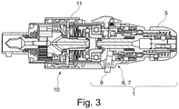
- the manual drive unit (housing) 6 is activated and driven via a lever 9 .
- the lever 9 is designed in the manner of a crank and is adapted to the size of a human hand. Ie the lever 9 is mounted in the housing 6 in such a way that the housing 6 is rotated about the central axis of the tool holder and thus the torque transmission elements can be driven.
- the lever 9 is but pivotally mounted in the axial direction of the tool holder, as in the 3 is shown.
- a lever extension protruding into the interior of the housing is coupled to the ratchet output element in such a way that it can be displaced in the axial direction by pivoting the lever 9 .
- the ratchet output element has a drive in the form of a radial projection which acts directly or indirectly on the intermediate/selector component of the ratchet in order to drive it, if necessary, according to the axial movement of the ratchet output element.
- the intermediate/selection component of the ratchet is taken into an axial position in which it meshes with one of the two torque transmission elements can come.
- the ratchet function is activated.
- a separating clutch is implemented as it were.
- a torque limiting device 10 is also present between the manual ratchet, in particular between the ratchet output element and the drive-side clutch 3 . This can be set manually Can be unlocked and locked, e.g. via a rotary handle.
- the turning handle is provided with the reference number 11 .
Landscapes
- Health & Medical Sciences (AREA)
- Surgery (AREA)
- Life Sciences & Earth Sciences (AREA)
- Engineering & Computer Science (AREA)
- Heart & Thoracic Surgery (AREA)
- Medical Informatics (AREA)
- Nuclear Medicine, Radiotherapy & Molecular Imaging (AREA)
- Oral & Maxillofacial Surgery (AREA)
- Dentistry (AREA)
- Biomedical Technology (AREA)
- Veterinary Medicine (AREA)
- Orthopedic Medicine & Surgery (AREA)
- Molecular Biology (AREA)
- Animal Behavior & Ethology (AREA)
- General Health & Medical Sciences (AREA)
- Public Health (AREA)
- Mechanical Engineering (AREA)
- Surgical Instruments (AREA)
- Dental Tools And Instruments Or Auxiliary Dental Instruments (AREA)
- Manipulator (AREA)
Applications Claiming Priority (3)
| Application Number | Priority Date | Filing Date | Title |
|---|---|---|---|
| DE102015111878.5A DE102015111878A1 (de) | 2015-07-22 | 2015-07-22 | Platzsparende Ratscheinheit mit Freilauf |
| DE102015111877.7A DE102015111877A1 (de) | 2015-07-22 | 2015-07-22 | Werkzeugaufnahmeaufsatz für chirurgische Bohrmaschine mit zusätzlicher manueller Antriebseinheit und chirurgische Bohrmaschine |
| PCT/EP2016/065988 WO2017012877A2 (de) | 2015-07-22 | 2016-07-06 | Werkzeugaufnahmeaufsatz für chirurgische bohrmaschine mit zusätzlicher manueller antriebseinheit und chirurgische bohrmaschine |
Publications (2)
| Publication Number | Publication Date |
|---|---|
| EP3324859A2 EP3324859A2 (de) | 2018-05-30 |
| EP3324859B1 true EP3324859B1 (de) | 2022-03-23 |
Family
ID=56345163
Family Applications (1)
| Application Number | Title | Priority Date | Filing Date |
|---|---|---|---|
| EP16734715.2A Active EP3324859B1 (de) | 2015-07-22 | 2016-07-06 | Werkzeugaufnahmeaufsatz für chirurgische bohrmaschine mit zusätzlicher manueller antriebseinheit und chirurgische bohrmaschine |
Country Status (7)
| Country | Link |
|---|---|
| US (1) | US10702284B2 (https=) |
| EP (1) | EP3324859B1 (https=) |
| JP (1) | JP2018520793A (https=) |
| CN (1) | CN107847235B (https=) |
| DE (1) | DE102015111877A1 (https=) |
| ES (1) | ES2914199T3 (https=) |
| WO (1) | WO2017012877A2 (https=) |
Families Citing this family (13)
| Publication number | Priority date | Publication date | Assignee | Title |
|---|---|---|---|---|
| DE102015111878A1 (de) | 2015-07-22 | 2017-01-26 | Aesculap Ag | Platzsparende Ratscheinheit mit Freilauf |
| DE102015111877A1 (de) * | 2015-07-22 | 2017-01-26 | Aesculap Ag | Werkzeugaufnahmeaufsatz für chirurgische Bohrmaschine mit zusätzlicher manueller Antriebseinheit und chirurgische Bohrmaschine |
| USD919088S1 (en) * | 2019-03-13 | 2021-05-11 | Laurent Fumex | Medical drill |
| CN110522493B (zh) * | 2019-08-14 | 2022-05-03 | 蚌埠医学院第一附属医院 | 一种开颅手术用颅骨铣刀 |
| US11426246B2 (en) * | 2019-08-15 | 2022-08-30 | Verb Surgical Inc. | Closure joint engagement for surgical tool |
| US11723672B2 (en) * | 2020-03-18 | 2023-08-15 | Shukla Medical | Chuck assembly for a medical device |
| US12023014B2 (en) | 2020-04-10 | 2024-07-02 | Nextremity Solutions, Inc. | Ratcheting handle for medical instrument |
| US11944502B2 (en) | 2020-04-10 | 2024-04-02 | Medartis Ag | Torque limiting ratcheting handle for medical instrument |
| GB202104353D0 (en) * | 2021-03-26 | 2021-05-12 | Depuy Ireland Ultd Co | Improvements in and relating to connections |
| US20240173069A1 (en) * | 2021-03-31 | 2024-05-30 | Hoogland Spine Products Gmbh | Set of surgical tools for spinal facet therapy |
| US12304037B2 (en) | 2021-11-03 | 2025-05-20 | Aob Products Company | Torque driver |
| CN114366272B (zh) * | 2021-12-16 | 2023-10-13 | 芜湖锐进医疗设备有限公司 | 一种可正反调节的棘轮手柄 |
| CN115227348B (zh) * | 2022-07-20 | 2026-04-07 | 上海微创医疗机器人(集团)股份有限公司 | 植入装置及手术机器人 |
Citations (2)
| Publication number | Priority date | Publication date | Assignee | Title |
|---|---|---|---|---|
| DE19942292C2 (de) * | 1999-09-04 | 2001-09-27 | Daimler Chrysler Ag | Zwischenglied für eine Handschrauberwelle |
| DE102011088252B4 (de) * | 2011-12-12 | 2013-11-28 | Schünke GmbH | Ratschenaufsatz zum Antrieb von Schraubwerkzeugen |
Family Cites Families (56)
| Publication number | Priority date | Publication date | Assignee | Title |
|---|---|---|---|---|
| US3120845A (en) | 1961-02-20 | 1964-02-11 | David B Horner | Self-powered surgical drill |
| DE1871193U (de) * | 1962-12-19 | 1963-04-25 | Ford Werke Ag | Vorrichtung zum anziehen von schrauben. |
| JPS4413999Y1 (https=) * | 1965-06-28 | 1969-06-12 | ||
| DE3146494C2 (de) * | 1981-11-24 | 1986-10-30 | Black & Decker, Inc. (Eine Gesellschaft N.D.Ges.D. Staates Delaware), Newark, Del. | Elektrowerkzeug, insbesondere Handwerkzeug, mit Drehmomentüberwachung |
| JPH0624867U (ja) * | 1992-08-04 | 1994-04-05 | イワブチ株式会社 | ねじ締付け具 |
| GB9304540D0 (en) * | 1993-03-05 | 1993-04-21 | Black & Decker Inc | Power tool and mechanism |
| DE4342464A1 (de) * | 1993-12-13 | 1995-06-14 | Joerg R Bauer | Schraubenschlüssel zum Fest- oder Losdrehen einer Schraube oder Mutter |
| US5613585A (en) | 1995-05-02 | 1997-03-25 | Beere Precision Medical Instruments, Inc. | Ratcheting screwdriver |
| US5619891A (en) | 1995-11-06 | 1997-04-15 | Beere Precision Medical Instruments, Inc. | Ratcheting screwdriver |
| EP0803319B1 (en) | 1996-04-26 | 2003-02-19 | Nippei Toyama Corporation | Tool change device and tool change method |
| US5794715A (en) * | 1996-07-08 | 1998-08-18 | Linvatec Corporation | Rotary tool head |
| DE19730300A1 (de) | 1997-03-07 | 1998-09-17 | Engelbert Gmeilbauer | Ratscheneinrichtung |
| DE29723472U1 (de) | 1997-03-07 | 1998-09-10 | Gmeilbauer, Engelbert, 82229 Seefeld | Ratscheneinrichtung |
| US5741263A (en) | 1997-04-18 | 1998-04-21 | Midas Rex Pneumatic Tools, Inc. | Mutiple flat quick release coupling |
| DE29819294U1 (de) | 1998-10-29 | 1999-04-15 | Gmeilbauer, Engelbert, 82229 Seefeld | Schraubendreher mit Freilaufratsche im Kugelschreiberformat |
| EP2322104B1 (en) * | 2000-02-18 | 2017-10-25 | Stryker Corporation | Surgical handpiece with a push rod that both transfers rotational movement to an output drive shaft and that actuates a cutting accessory locking assembly |
| US7066940B2 (en) * | 2001-03-21 | 2006-06-27 | Medtronic, Inc. | Surgical instrument with rotary cutting member and quick release coupling arrangement |
| CN2507614Y (zh) * | 2001-10-21 | 2002-08-28 | 易健生 | 带手动加力杆装置的多用起子 |
| US6658970B2 (en) | 2001-12-14 | 2003-12-09 | Hsuan-Sen Shiao | Ratchet screwdriver |
| US6817458B1 (en) | 2002-01-16 | 2004-11-16 | Michael T. Gauthier | Ratcheting mechanism |
| DE10311455B3 (de) | 2003-03-15 | 2004-09-16 | Aesculap Ag & Co. Kg | Kupplung für ein chirurgisches Drehantriebs-Handstück |
| TWI290880B (en) | 2004-07-23 | 2007-12-11 | Hou-Fei Hu | High torque ratchet screwdriver |
| US7181997B1 (en) | 2005-01-18 | 2007-02-27 | Pilling Weck, Incorporated | Ratchet screwdriver and method of making same |
| US20060248987A1 (en) | 2005-05-05 | 2006-11-09 | Patrick White | Ratchet handle |
| US8021365B2 (en) * | 2005-07-11 | 2011-09-20 | Kyphon Sarl | Surgical device having interchangeable components and methods of use |
| US20070006692A1 (en) * | 2005-07-11 | 2007-01-11 | Phan Christopher U | Torque limiting device |
| CH698913B1 (fr) * | 2006-05-26 | 2009-12-15 | Hader Sa | Outil dynamométrique à usage médical. |
| DE102006057283A1 (de) | 2006-12-05 | 2008-06-12 | Robert Bosch Gmbh | Handwerkzeug |
| DE102007048928A1 (de) * | 2007-10-12 | 2009-04-16 | Daimler Ag | Spindelantrieb zum Antreiben eines bewegbaren Bauelements eines Kraftwagens |
| US9078671B2 (en) * | 2008-04-17 | 2015-07-14 | Warsaw Orthopedic, Inc. | Surgical tool |
| EP2138273B1 (en) * | 2008-06-25 | 2012-02-15 | Robert Bosch GmbH | Rotary tool having a manual ratchet mechanism |
| US8597316B2 (en) | 2008-09-05 | 2013-12-03 | Stryker Corporation | Cutting accessory for use with a medical/surgical powered handpiece, the accessory having retention features that facilitate the fine or coarse adjustment of the extension of the accessory shaft |
| TW201109127A (en) * | 2009-09-15 | 2011-03-16 | Jin-Tan Huang | Torque adjuster |
| US8714056B2 (en) * | 2010-09-03 | 2014-05-06 | Greatbatch Ltd. | Torque limiting mechanism with lock bushing |
| US10413345B2 (en) * | 2010-11-12 | 2019-09-17 | David B. Plotkin | Universal bone screw screwdriver |
| US8801713B2 (en) | 2011-04-07 | 2014-08-12 | DePuy Synthes Products, LLC | Surgical drill instrument with motor and locking mechanism to receive an attachment and a cutting burr |
| US8786233B2 (en) | 2011-04-27 | 2014-07-22 | Medtronic Xomed, Inc. | Electric ratchet for a powered screwdriver |
| US8985593B1 (en) * | 2011-07-14 | 2015-03-24 | Bradshaw Medical, Inc. | Self-locking internal adapter for D-shaped orthopedic adjustment tools |
| WO2013020877A1 (de) * | 2011-08-05 | 2013-02-14 | Charité - Universitätsmedizin Berlin | Medizinische vorrichtung |
| WO2013143563A1 (en) * | 2012-03-30 | 2013-10-03 | Stryker Trauma Ag | Torque-limiting assembly for a surgical powertool |
| JP6008319B2 (ja) * | 2012-10-12 | 2016-10-19 | パナソニックIpマネジメント株式会社 | インパクト回転工具 |
| WO2014164293A2 (en) * | 2013-03-12 | 2014-10-09 | Eca Medical Instruments | Ratcheting torque wrench |
| US20140277203A1 (en) * | 2013-03-14 | 2014-09-18 | Ebi, Llc | Torque multiplier, limiter, and counter-torque combinations and methods |
| US9701000B2 (en) * | 2013-07-19 | 2017-07-11 | Panasonic Intellectual Property Management Co., Ltd. | Impact rotation tool and impact rotation tool attachment |
| JP6380924B2 (ja) * | 2014-01-06 | 2018-08-29 | パナソニックIpマネジメント株式会社 | インパクト回転工具の慣性モーメントの測定方法とその測定方法を用いたインパクト回転工具 |
| US9795395B2 (en) * | 2014-06-10 | 2017-10-24 | Medos International Sarl | Retro-cutting instrument with adjustable limit setting |
| US9936961B2 (en) * | 2014-09-26 | 2018-04-10 | DePuy Synthes Products, Inc. | Surgical tool with feedback |
| DE102015111877A1 (de) * | 2015-07-22 | 2017-01-26 | Aesculap Ag | Werkzeugaufnahmeaufsatz für chirurgische Bohrmaschine mit zusätzlicher manueller Antriebseinheit und chirurgische Bohrmaschine |
| DE102015111878A1 (de) * | 2015-07-22 | 2017-01-26 | Aesculap Ag | Platzsparende Ratscheinheit mit Freilauf |
| US10213270B2 (en) * | 2015-12-02 | 2019-02-26 | Lomack Industrial Co. Ltd. | Small disposable torque limiting driving tool with rubber grip |
| US20170314711A1 (en) * | 2016-04-29 | 2017-11-02 | Diba Industries, Inc. | Tightening tool for torque-limited fittings and systems including the torque-limited fittings |
| US20180104801A1 (en) * | 2016-10-17 | 2018-04-19 | Bradshaw Medical, Inc. | Torque-limiting driver with embodied roller |
| US10874406B2 (en) | 2017-02-28 | 2020-12-29 | MFr Technologies, Inc. | Handheld surgical instrument |
| US10695073B2 (en) * | 2017-08-22 | 2020-06-30 | Arthrex, Inc. | Control system for retrograde drill medical device |
| US10779872B2 (en) * | 2017-11-02 | 2020-09-22 | Medos International Sarl | Bone anchor insertion instruments and methods |
| WO2019147964A1 (en) | 2018-01-26 | 2019-08-01 | Mako Surgical Corp. | End effectors and methods for driving tools guided by surgical robotic systems |
-
2015
- 2015-07-22 DE DE102015111877.7A patent/DE102015111877A1/de not_active Withdrawn
-
2016
- 2016-07-06 EP EP16734715.2A patent/EP3324859B1/de active Active
- 2016-07-06 CN CN201680043019.1A patent/CN107847235B/zh active Active
- 2016-07-06 ES ES16734715T patent/ES2914199T3/es active Active
- 2016-07-06 US US15/744,960 patent/US10702284B2/en active Active
- 2016-07-06 JP JP2018502233A patent/JP2018520793A/ja active Pending
- 2016-07-06 WO PCT/EP2016/065988 patent/WO2017012877A2/de not_active Ceased
Patent Citations (2)
| Publication number | Priority date | Publication date | Assignee | Title |
|---|---|---|---|---|
| DE19942292C2 (de) * | 1999-09-04 | 2001-09-27 | Daimler Chrysler Ag | Zwischenglied für eine Handschrauberwelle |
| DE102011088252B4 (de) * | 2011-12-12 | 2013-11-28 | Schünke GmbH | Ratschenaufsatz zum Antrieb von Schraubwerkzeugen |
Also Published As
| Publication number | Publication date |
|---|---|
| DE102015111877A1 (de) | 2017-01-26 |
| CN107847235A (zh) | 2018-03-27 |
| WO2017012877A3 (de) | 2017-05-11 |
| WO2017012877A2 (de) | 2017-01-26 |
| ES2914199T3 (es) | 2022-06-08 |
| EP3324859A2 (de) | 2018-05-30 |
| US10702284B2 (en) | 2020-07-07 |
| JP2018520793A (ja) | 2018-08-02 |
| CN107847235B (zh) | 2022-03-08 |
| US20180206856A1 (en) | 2018-07-26 |
Similar Documents
| Publication | Publication Date | Title |
|---|---|---|
| EP3324859B1 (de) | Werkzeugaufnahmeaufsatz für chirurgische bohrmaschine mit zusätzlicher manueller antriebseinheit und chirurgische bohrmaschine | |
| EP2962651B1 (de) | Medizinischer schraubendreher und schaft für den medizinischen schraubendreher | |
| EP3324860B1 (de) | Platzsparende ratscheinheit mit freilauf | |
| EP2389879B1 (de) | Medizinisches Instrument mit abnehmbarem Griff | |
| EP2305145A1 (de) | Zerlegbares medizinisches Zangensystem | |
| EP3777720B1 (de) | Medizinische antriebseinheit der handheld-bauart mit sensoreinrichtung und kick-back-control | |
| EP1952947A1 (de) | Kraftgetriebenes Handwerkzeug zum Bohren und/oder Schrauben | |
| EP2910202B1 (de) | Instrument zur Durchführung medizinischer Eingriffe | |
| WO2017144172A1 (de) | Halterung für ein instrument | |
| EP4321107A1 (de) | Medizinisches motorhandstück mit rast- und/oder anschlageinheit | |
| DE102014104367A1 (de) | Bohrvorrichtung und Rutschkupplung für eine Bohrvorrichtung | |
| EP3372343B1 (de) | Anordnung aus einem reaktionsmomente ableitenden stützarm und einem drehschrauber | |
| EP3313622B1 (de) | Handwerkzeugmaschine | |
| EP2702950A1 (de) | Medizinisches Werkzeugsystem, sowie Handgriff und Werkzeug für ein medizinisches Werkzeugsystem | |
| CH697058A5 (de) | Bohrfutter. | |
| EP3005963B1 (de) | Elektrische werkzeugmaschine, insbesondere elektrischer schraubendreher für die verwendung in der chirurgie | |
| US10874442B2 (en) | Multi-mode torque drivers employing inner surfaces compatible with pedicle screw guide wires, and related systems and methods | |
| DE102021132076B4 (de) | Spannvorrichtung | |
| EP4178471B1 (de) | Medizinisches instrument und verfahren | |
| DE102022119979A1 (de) | Medizinisches Motorhandstück für 2-in-1-Bedienung sowie medizinisches Handinstrument mit 2-in-1-Bedienung | |
| EP3609653B1 (de) | Drehschrauber | |
| DE102025117341A1 (de) | Anbauteil für ein angetriebenes werkzeug, angetriebenes werkzeug sowie halte- und antriebseinheit zum anziehen einer schraube und mutter | |
| EP3158956A1 (de) | Mikrochirurgisches instrument, handhabe und motorblock für ein mikrochirurgisches instrument | |
| DE102016101822A1 (de) | Instrument zum Führen eines Stabs in eine Implantataufnahme | |
| EP1952953A1 (de) | Handwerkzeug zum Bohren und/oder Schrauben |
Legal Events
| Date | Code | Title | Description |
|---|---|---|---|
| STAA | Information on the status of an ep patent application or granted ep patent |
Free format text: STATUS: THE INTERNATIONAL PUBLICATION HAS BEEN MADE |
|
| PUAI | Public reference made under article 153(3) epc to a published international application that has entered the european phase |
Free format text: ORIGINAL CODE: 0009012 |
|
| STAA | Information on the status of an ep patent application or granted ep patent |
Free format text: STATUS: REQUEST FOR EXAMINATION WAS MADE |
|
| 17P | Request for examination filed |
Effective date: 20180202 |
|
| AK | Designated contracting states |
Kind code of ref document: A2 Designated state(s): AL AT BE BG CH CY CZ DE DK EE ES FI FR GB GR HR HU IE IS IT LI LT LU LV MC MK MT NL NO PL PT RO RS SE SI SK SM TR |
|
| AX | Request for extension of the european patent |
Extension state: BA ME |
|
| DAV | Request for validation of the european patent (deleted) | ||
| DAX | Request for extension of the european patent (deleted) | ||
| GRAP | Despatch of communication of intention to grant a patent |
Free format text: ORIGINAL CODE: EPIDOSNIGR1 |
|
| STAA | Information on the status of an ep patent application or granted ep patent |
Free format text: STATUS: GRANT OF PATENT IS INTENDED |
|
| RIC1 | Information provided on ipc code assigned before grant |
Ipc: B25F 5/02 20060101ALI20210907BHEP Ipc: B25F 3/00 20060101ALI20210907BHEP Ipc: B25B 23/14 20060101ALI20210907BHEP Ipc: B25B 21/00 20060101ALI20210907BHEP Ipc: B25B 13/46 20060101ALI20210907BHEP Ipc: A61B 17/00 20060101ALI20210907BHEP Ipc: A61B 17/16 20060101AFI20210907BHEP |
|
| INTG | Intention to grant announced |
Effective date: 20211006 |
|
| GRAS | Grant fee paid |
Free format text: ORIGINAL CODE: EPIDOSNIGR3 |
|
| GRAA | (expected) grant |
Free format text: ORIGINAL CODE: 0009210 |
|
| STAA | Information on the status of an ep patent application or granted ep patent |
Free format text: STATUS: THE PATENT HAS BEEN GRANTED |
|
| AK | Designated contracting states |
Kind code of ref document: B1 Designated state(s): AL AT BE BG CH CY CZ DE DK EE ES FI FR GB GR HR HU IE IS IT LI LT LU LV MC MK MT NL NO PL PT RO RS SE SI SK SM TR |
|
| REG | Reference to a national code |
Ref country code: GB Ref legal event code: FG4D Free format text: NOT ENGLISH |
|
| REG | Reference to a national code |
Ref country code: CH Ref legal event code: EP |
|
| REG | Reference to a national code |
Ref country code: DE Ref legal event code: R096 Ref document number: 502016014672 Country of ref document: DE |
|
| REG | Reference to a national code |
Ref country code: IE Ref legal event code: FG4D Free format text: LANGUAGE OF EP DOCUMENT: GERMAN |
|
| REG | Reference to a national code |
Ref country code: AT Ref legal event code: REF Ref document number: 1476910 Country of ref document: AT Kind code of ref document: T Effective date: 20220415 |
|
| REG | Reference to a national code |
Ref country code: ES Ref legal event code: FG2A Ref document number: 2914199 Country of ref document: ES Kind code of ref document: T3 Effective date: 20220608 |
|
| REG | Reference to a national code |
Ref country code: LT Ref legal event code: MG9D |
|
| REG | Reference to a national code |
Ref country code: NL Ref legal event code: MP Effective date: 20220323 |
|
| PG25 | Lapsed in a contracting state [announced via postgrant information from national office to epo] |
Ref country code: SE Free format text: LAPSE BECAUSE OF FAILURE TO SUBMIT A TRANSLATION OF THE DESCRIPTION OR TO PAY THE FEE WITHIN THE PRESCRIBED TIME-LIMIT Effective date: 20220323 Ref country code: RS Free format text: LAPSE BECAUSE OF FAILURE TO SUBMIT A TRANSLATION OF THE DESCRIPTION OR TO PAY THE FEE WITHIN THE PRESCRIBED TIME-LIMIT Effective date: 20220323 Ref country code: NO Free format text: LAPSE BECAUSE OF FAILURE TO SUBMIT A TRANSLATION OF THE DESCRIPTION OR TO PAY THE FEE WITHIN THE PRESCRIBED TIME-LIMIT Effective date: 20220623 Ref country code: LT Free format text: LAPSE BECAUSE OF FAILURE TO SUBMIT A TRANSLATION OF THE DESCRIPTION OR TO PAY THE FEE WITHIN THE PRESCRIBED TIME-LIMIT Effective date: 20220323 Ref country code: HR Free format text: LAPSE BECAUSE OF FAILURE TO SUBMIT A TRANSLATION OF THE DESCRIPTION OR TO PAY THE FEE WITHIN THE PRESCRIBED TIME-LIMIT Effective date: 20220323 Ref country code: BG Free format text: LAPSE BECAUSE OF FAILURE TO SUBMIT A TRANSLATION OF THE DESCRIPTION OR TO PAY THE FEE WITHIN THE PRESCRIBED TIME-LIMIT Effective date: 20220623 |
|
| PG25 | Lapsed in a contracting state [announced via postgrant information from national office to epo] |
Ref country code: LV Free format text: LAPSE BECAUSE OF FAILURE TO SUBMIT A TRANSLATION OF THE DESCRIPTION OR TO PAY THE FEE WITHIN THE PRESCRIBED TIME-LIMIT Effective date: 20220323 Ref country code: GR Free format text: LAPSE BECAUSE OF FAILURE TO SUBMIT A TRANSLATION OF THE DESCRIPTION OR TO PAY THE FEE WITHIN THE PRESCRIBED TIME-LIMIT Effective date: 20220624 Ref country code: FI Free format text: LAPSE BECAUSE OF FAILURE TO SUBMIT A TRANSLATION OF THE DESCRIPTION OR TO PAY THE FEE WITHIN THE PRESCRIBED TIME-LIMIT Effective date: 20220323 |
|
| PG25 | Lapsed in a contracting state [announced via postgrant information from national office to epo] |
Ref country code: NL Free format text: LAPSE BECAUSE OF FAILURE TO SUBMIT A TRANSLATION OF THE DESCRIPTION OR TO PAY THE FEE WITHIN THE PRESCRIBED TIME-LIMIT Effective date: 20220323 |
|
| PG25 | Lapsed in a contracting state [announced via postgrant information from national office to epo] |
Ref country code: SM Free format text: LAPSE BECAUSE OF FAILURE TO SUBMIT A TRANSLATION OF THE DESCRIPTION OR TO PAY THE FEE WITHIN THE PRESCRIBED TIME-LIMIT Effective date: 20220323 Ref country code: SK Free format text: LAPSE BECAUSE OF FAILURE TO SUBMIT A TRANSLATION OF THE DESCRIPTION OR TO PAY THE FEE WITHIN THE PRESCRIBED TIME-LIMIT Effective date: 20220323 Ref country code: RO Free format text: LAPSE BECAUSE OF FAILURE TO SUBMIT A TRANSLATION OF THE DESCRIPTION OR TO PAY THE FEE WITHIN THE PRESCRIBED TIME-LIMIT Effective date: 20220323 Ref country code: PT Free format text: LAPSE BECAUSE OF FAILURE TO SUBMIT A TRANSLATION OF THE DESCRIPTION OR TO PAY THE FEE WITHIN THE PRESCRIBED TIME-LIMIT Effective date: 20220725 Ref country code: EE Free format text: LAPSE BECAUSE OF FAILURE TO SUBMIT A TRANSLATION OF THE DESCRIPTION OR TO PAY THE FEE WITHIN THE PRESCRIBED TIME-LIMIT Effective date: 20220323 Ref country code: CZ Free format text: LAPSE BECAUSE OF FAILURE TO SUBMIT A TRANSLATION OF THE DESCRIPTION OR TO PAY THE FEE WITHIN THE PRESCRIBED TIME-LIMIT Effective date: 20220323 |
|
| PG25 | Lapsed in a contracting state [announced via postgrant information from national office to epo] |
Ref country code: PL Free format text: LAPSE BECAUSE OF FAILURE TO SUBMIT A TRANSLATION OF THE DESCRIPTION OR TO PAY THE FEE WITHIN THE PRESCRIBED TIME-LIMIT Effective date: 20220323 Ref country code: IS Free format text: LAPSE BECAUSE OF FAILURE TO SUBMIT A TRANSLATION OF THE DESCRIPTION OR TO PAY THE FEE WITHIN THE PRESCRIBED TIME-LIMIT Effective date: 20220723 Ref country code: AL Free format text: LAPSE BECAUSE OF FAILURE TO SUBMIT A TRANSLATION OF THE DESCRIPTION OR TO PAY THE FEE WITHIN THE PRESCRIBED TIME-LIMIT Effective date: 20220323 |
|
| REG | Reference to a national code |
Ref country code: DE Ref legal event code: R097 Ref document number: 502016014672 Country of ref document: DE |
|
| PLBE | No opposition filed within time limit |
Free format text: ORIGINAL CODE: 0009261 |
|
| STAA | Information on the status of an ep patent application or granted ep patent |
Free format text: STATUS: NO OPPOSITION FILED WITHIN TIME LIMIT |
|
| PG25 | Lapsed in a contracting state [announced via postgrant information from national office to epo] |
Ref country code: DK Free format text: LAPSE BECAUSE OF FAILURE TO SUBMIT A TRANSLATION OF THE DESCRIPTION OR TO PAY THE FEE WITHIN THE PRESCRIBED TIME-LIMIT Effective date: 20220323 |
|
| PG25 | Lapsed in a contracting state [announced via postgrant information from national office to epo] |
Ref country code: MC Free format text: LAPSE BECAUSE OF FAILURE TO SUBMIT A TRANSLATION OF THE DESCRIPTION OR TO PAY THE FEE WITHIN THE PRESCRIBED TIME-LIMIT Effective date: 20220323 |
|
| REG | Reference to a national code |
Ref country code: CH Ref legal event code: PL |
|
| 26N | No opposition filed |
Effective date: 20230102 |
|
| REG | Reference to a national code |
Ref country code: BE Ref legal event code: MM Effective date: 20220731 |
|
| PG25 | Lapsed in a contracting state [announced via postgrant information from national office to epo] |
Ref country code: LU Free format text: LAPSE BECAUSE OF NON-PAYMENT OF DUE FEES Effective date: 20220706 Ref country code: LI Free format text: LAPSE BECAUSE OF NON-PAYMENT OF DUE FEES Effective date: 20220731 Ref country code: CH Free format text: LAPSE BECAUSE OF NON-PAYMENT OF DUE FEES Effective date: 20220731 |
|
| PG25 | Lapsed in a contracting state [announced via postgrant information from national office to epo] |
Ref country code: SI Free format text: LAPSE BECAUSE OF FAILURE TO SUBMIT A TRANSLATION OF THE DESCRIPTION OR TO PAY THE FEE WITHIN THE PRESCRIBED TIME-LIMIT Effective date: 20220323 Ref country code: BE Free format text: LAPSE BECAUSE OF NON-PAYMENT OF DUE FEES Effective date: 20220731 |
|
| PG25 | Lapsed in a contracting state [announced via postgrant information from national office to epo] |
Ref country code: IE Free format text: LAPSE BECAUSE OF NON-PAYMENT OF DUE FEES Effective date: 20220706 |
|
| P01 | Opt-out of the competence of the unified patent court (upc) registered |
Effective date: 20230807 |
|
| REG | Reference to a national code |
Ref country code: AT Ref legal event code: MM01 Ref document number: 1476910 Country of ref document: AT Kind code of ref document: T Effective date: 20220706 |
|
| PG25 | Lapsed in a contracting state [announced via postgrant information from national office to epo] |
Ref country code: AT Free format text: LAPSE BECAUSE OF NON-PAYMENT OF DUE FEES Effective date: 20220706 |
|
| PG25 | Lapsed in a contracting state [announced via postgrant information from national office to epo] |
Ref country code: HU Free format text: LAPSE BECAUSE OF FAILURE TO SUBMIT A TRANSLATION OF THE DESCRIPTION OR TO PAY THE FEE WITHIN THE PRESCRIBED TIME-LIMIT; INVALID AB INITIO Effective date: 20160706 |
|
| PG25 | Lapsed in a contracting state [announced via postgrant information from national office to epo] |
Ref country code: MK Free format text: LAPSE BECAUSE OF FAILURE TO SUBMIT A TRANSLATION OF THE DESCRIPTION OR TO PAY THE FEE WITHIN THE PRESCRIBED TIME-LIMIT Effective date: 20220323 Ref country code: CY Free format text: LAPSE BECAUSE OF FAILURE TO SUBMIT A TRANSLATION OF THE DESCRIPTION OR TO PAY THE FEE WITHIN THE PRESCRIBED TIME-LIMIT Effective date: 20220323 |
|
| PG25 | Lapsed in a contracting state [announced via postgrant information from national office to epo] |
Ref country code: TR Free format text: LAPSE BECAUSE OF FAILURE TO SUBMIT A TRANSLATION OF THE DESCRIPTION OR TO PAY THE FEE WITHIN THE PRESCRIBED TIME-LIMIT Effective date: 20220323 |
|
| PG25 | Lapsed in a contracting state [announced via postgrant information from national office to epo] |
Ref country code: MT Free format text: LAPSE BECAUSE OF FAILURE TO SUBMIT A TRANSLATION OF THE DESCRIPTION OR TO PAY THE FEE WITHIN THE PRESCRIBED TIME-LIMIT Effective date: 20220323 |
|
| PGFP | Annual fee paid to national office [announced via postgrant information from national office to epo] |
Ref country code: ES Payment date: 20250819 Year of fee payment: 10 |
|
| PGFP | Annual fee paid to national office [announced via postgrant information from national office to epo] |
Ref country code: DE Payment date: 20250722 Year of fee payment: 10 |
|
| PGFP | Annual fee paid to national office [announced via postgrant information from national office to epo] |
Ref country code: IT Payment date: 20250731 Year of fee payment: 10 |
|
| PGFP | Annual fee paid to national office [announced via postgrant information from national office to epo] |
Ref country code: GB Payment date: 20250724 Year of fee payment: 10 |
|
| PGFP | Annual fee paid to national office [announced via postgrant information from national office to epo] |
Ref country code: FR Payment date: 20250723 Year of fee payment: 10 |